

Page 1
Product Category: Personal Computers
Marketing Name / Model
[List multiple models if applicable.]
HP Envy Phoenix 800 Desktop PC
1.0 Items Requiring Selective Treatment
Item Description
Notes
Quantity
of items
included
in product
Printed Circuit Boards (PCB) or Printed Circuit
Assemblies (PCA)
With a surface greater than 10 sq cm
MB, Memory,HDD PCA,ODD PCA,PSU PCA(4)
8
Batteries
All types including standard alkaline and lithium coin
or button style batteries MB
1
Mercury-containing components
For example, mercury in lamps, display backlights,
scanner lamps, switches, batteries
0
Liquid Crystal Displays (LCD) with a surface greater
than 100 sq cm
Includes background illuminated displays with gas
discharge lamps
0
Cathode Ray Tubes (CRT)
0
Capacitors / condensers (Containing PCB/PCT)
0
Electrolytic Capacitors / Condensers measuring
greater than 2.5 cm in diameter or height
PSU
4
External electrical cables and cords
Power cord
1
Gas Discharge Lamps
0
Plastics containing Brominated Flame Retardants
weighing > 25 grams (not including PCBs or PCAs
already listed as a separate item above)
system fan,Cooler fan,PSU fan
3
Components and parts containing toner and ink,
including liquids, semi-liquids (gel/paste) and toner
Include the cartridges, print heads, tubes, vent
chambers, and service stations.
0
Components and waste containing asbestos
0
Product End-of-Life Disassembly Instructions
Purpose: The document is intended for use by end-of-life recyclers or treatment facilities. It provides the basic instructions
for the disassembly of HP products to remove components and materials requiring selective treatment, as defined by EU
directive 2002/96/EC, Waste Electrical and Electronic Equipment (WEEE).
1.1 Items listed below are classified as requiring selective treatment.
1.2 Enter the quantity of items contained within the product which require selective treatment in the right column, as
applicable.
EL-MF877-00 Page 1
Template Revision B
PSG instructions for this template are available at EL-MF877-01
Page 2

Components, parts and materials containing
refractory ceramic fibers
0
Components, parts and materials containing
radioactive substances
0
2.0 Tools Required
Tool Description
Tool Size (if
applicable)
Crisscross screw driver
2#
Hexagon screw driver
T15
Electric iron.
QUICK 310
3.0 Product Disassembly Process
List the type and size of the tools that would typically be used to disassemble the product to a point where components
and materials requiring selective treatment can be removed.
3.1 List the basic steps that should typically be followed to remove components and materials requiring selective treatment:
1. Remove access panel from the unit
2. Remove front panel from the unit
3. Remove ODD from the unit
4. Remove HDD from the unit
5. Take off FIO from the unit
6. Remove all the cables from the unit
7. Take off system fan from the unit
8. Take off PSU from the unit.
9. Take off Memory from the unit.
10. Take off CPU cooler from the unit.
11. Take off battery from the unit.
12. Take off PCA from the unit.
13. Open the PSU and PSU fan
14. Take off PSU PCA.
15. Take off CAP using electric iron.
3.2 Optional Graphic. If the disassembly process is complex, insert a graphic illustration below to identify the items
contained in the product that require selective treatment (with descriptions and arrows identifying locations).
EL-MF877-00 Page 2
Template Revision B
PSG instructions for this template are available at EL-MF877-01
Page 3
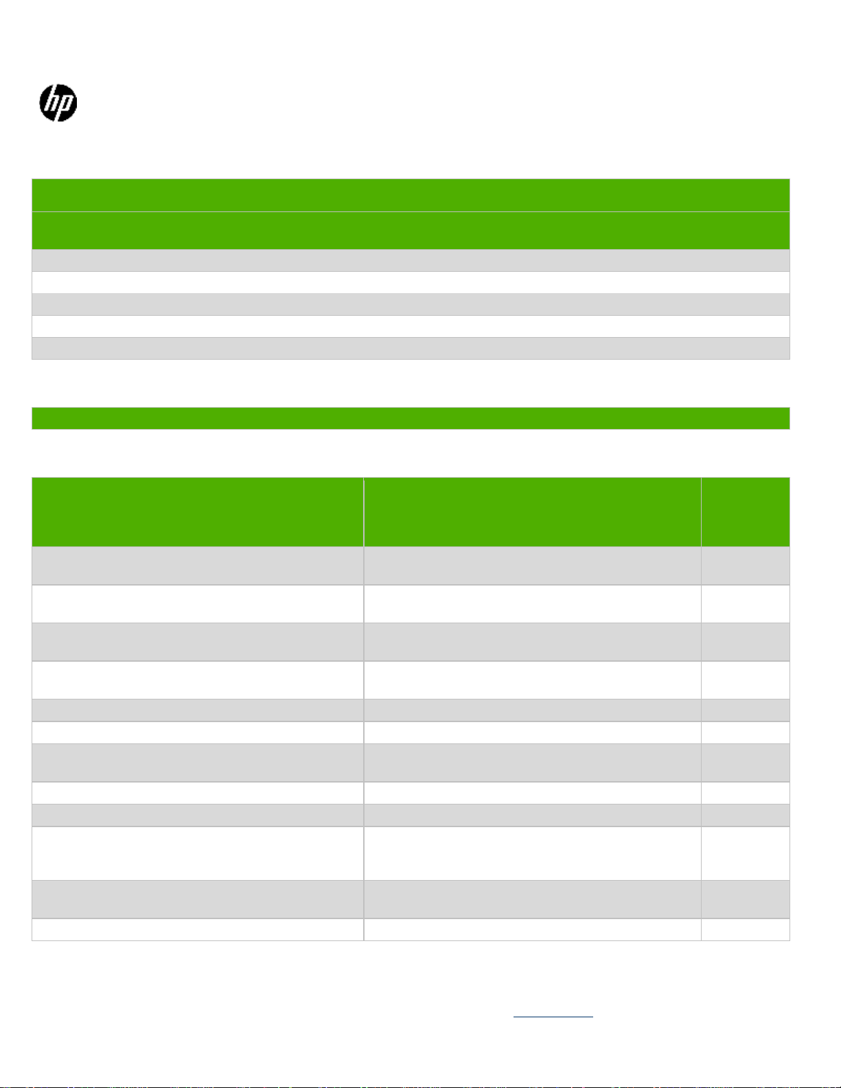
1. Remove access panel
from the unit.
Release screw on the access
panel. Griping the tab at the
end of access panel, pull
towards the rear and remove it
from unit.
EL-MF877-00 Page 3
Template Revision B
PSG instructions for this template are available at EL-MF877-01
Page 4
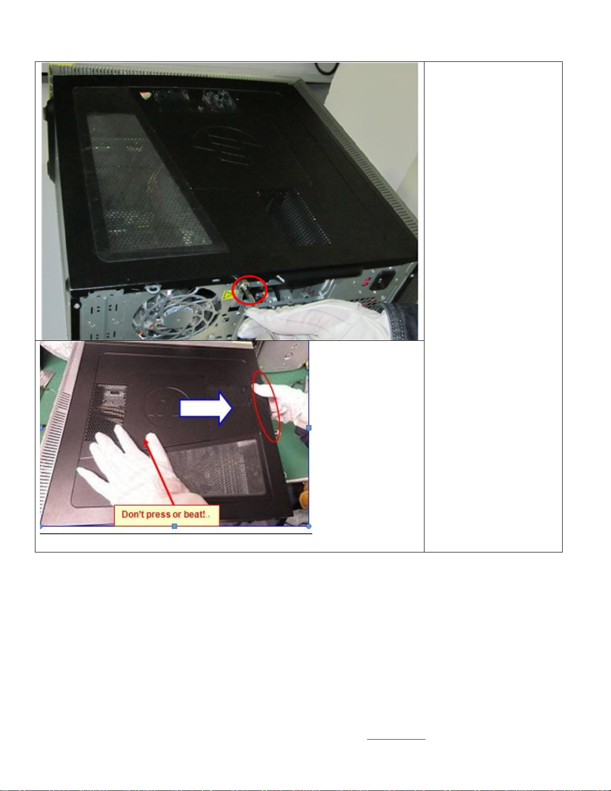
2. Remove front panel
from the unit.
Release 3 bezel latches from
chassis by pulling the bezel
latches outwards.
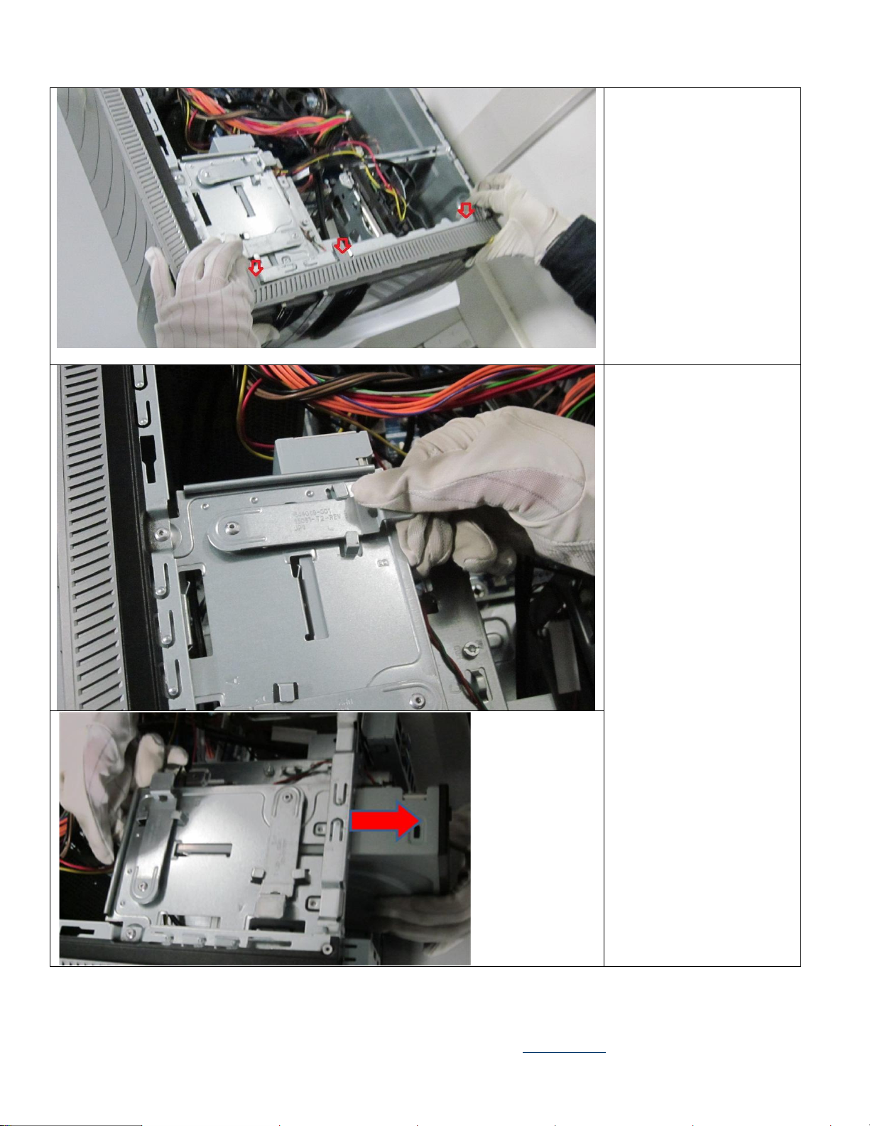
3 Remove ODD from the
unit
Rotate the metal blank bezel
and remove the ODD from the
cage.
EL-MF877-00 Page 4
Template Revision B
PSG instructions for this template are available at EL-MF877-01
Page 5

4.Remove HDD from the
unit.
Remove HDD from the latch
on the side of cage.
5 Take off FIO from the
unit.
Rotate the screw driver to
release FIO from the unit.
EL-MF877-00 Page 5
Template Revision B
PSG instructions for this template are available at EL-MF877-01
Page 6

6 Remove all the cables
from the unit.
7.Take off system fan from
the unit.
Rotate crisscross screw driver
to release system fan from the
unit.
EL-MF877-00 Page 6
Template Revision B
PSG instructions for this template are available at EL-MF877-01
Page 7

8.Take off PSU from the
unit.
Rotate screw driver to release
PSU from the unit.
9 Take off Memory from
the unit.
Release memory socket
levers by pulling outward.
EL-MF877-00 Page 7
Template Revision B
PSG instructions for this template are available at EL-MF877-01
Page 8

10 Take off CPU cooler
from the unit.
Rotate screw driver to loose
screw and then take off the
CPU cooler.
11. Take off battery from
the unit.
EL-MF877-00 Page 8
Template Revision B
PSG instructions for this template are available at EL-MF877-01
Page 9

12 Take off PCA from the
unit.
Rotate screw driver to
loose PCA from the unit.
13.Open the PSU and
PSU fan.
Rotate screw driver to
release the PSU cover
and fan.
EL-MF877-00 Page 9
Template Revision B
PSG instructions for this template are available at EL-MF877-01
Page 10

14.Take off PSU PCA.
Rotate screw driver to
release the PCA.
EL-MF877-00 Page 10
Template Revision B
PSG instructions for this template are available at EL-MF877-01
Page 11

15.Take off electrolytic
capacitors > 25mm
using electric iron
EL-MF877-00 Page 11
Template Revision B
PSG instructions for this template are available at EL-MF877-01
 Loading...