

Page 1

Contents
HP E8402A and E8404A VXI C-Size Mainframe User and Service Manual
Edition 1
Contents 3
HEWLETT-PACKARD WARRANTY STATEMENT ............................................11
Safety Symbols...........................................................................................................12
WARNINGS...............................................................................................................12
Declaration of Conformity..........................................................................................13
Reader Comment Sheet ..............................................................................................15
Chapter 1
Getting Started .............................................................................................................17
Product Overview.......................................................................................................17
Preparing Your VXI System for Use ..........................................................................18
AC Power Requirements .....................................................................................18
Positioning the Mainframe for Adequate Cooling ..............................................18
Connecting the
Mainframe to a Permanent Earth Ground ...........................................................19
Installing VXI Instruments.........................................................................................20
Installing C-Size Instruments ..............................................................................21
Installing A- and B-Size Instruments ..................................................................22
Configuring Your Mainframe.....................................................................................23
Setting the Enhanced Monitor VXI Logical Address .........................................23
RS-232 Interface .......................................................................... ......... ......... .....24
External +5V Supply ...........................................................................................24
Using the Remote Power-On Pins .......................................................................25
Disabling the On/Stdby Switch ...........................................................................26
Mainframe Options and Accessories..........................................................................27
Chapter 2
Using the Enhanced Monitor ......................................................................................29
Using the Enhanced Monitor......................................................................................31
Enhanced Monitor Fan Control..................................................................................36
Software Control of Fan Speed ...........................................................................36
Setting Enhanced Monitor Limits...............................................................................37
Temperature Limits .............................................................................................37
Current and Power Limits ...................................................................................37
Handling Warnings ............................................................................... ......... .....38
Save The Limits ..................................................................................................38
Enhanced Monitor Measurement Cycles....................................................................38
Using the History Queue.............................................................................................39
HISTory Queue ...................................................................................................39
RS-232 Programming.......................................................................... .......................40
Diagnostic Connector ........................................................ ......... ................................42
+5VC (pin 6) .......................................................................................................43
+12VC (pin 7) .....................................................................................................43
+5V STDBY (pins 8, 21) ....................................................................................43
SYSRESET* (pin 10) ..........................................................................................43
ACFAIL* (pin 23) ...............................................................................................43
Page 2

4 Contents
Chapter 3
Programming the Enhanced Monitor ........................................................................45
CALibration Subsystem..............................................................................................57
DISPlay Subsystem.....................................................................................................58
DISPlay[:WINDow] <display window>
DISPlay[:WINDow]? ..........................................................................................58
DISPlay[:WINDow]:STATe <state>
DISPlay[:WINDow]:STATe? ............................................................................. 60
DISPlay[:WINDow]:TEXT[:DATA] <string> ...................................................61
FORMat Subsystem....................................................................................................62
FORMat:BORDer <order>
FORMat:BORDer? .............................................................................................62
HISTory Subsystem....................................................................................................63
HISTory:BLOWer[:HISTogram]? <blower>[,MIN|MAX] ................................64
HISTory:CURRent:CMAXimum? <supply> .....................................................65
HISTory:CURRent[:HISTogram]? <supply>[,MIN|MAX] ...............................66
HISTory:CURRent:MAXimum? <supply> ........................................................67
HISTory:POWer:CMAXimum? <supply> .........................................................68
HISTory:POWer[:HISTogram]? <supply>[,MIN|MAX] ...................................69
HISTory:POWer:MAXimum? <supply> ............................................................70
HISTory:QUEue:COUNt? ..................................................................................71
HISTory:QUEue[:FETCh]? <event index> ........................................................72
HISTory:RESet[:ALL]
HISTory:RESet:BLOWer [<blower>]
HISTory:RESet:CURRent [<supply>]
HISTory:RESet:POWer [<supply>]
HISTory:RESet:QUEue
HISTory:RESet:TEMPeratu re [<s lo t>]
HISTory:RESet:VOLTage [<supply>] ...............................................................74
HISTory:TEMPerature:CMAXimum? <slot>
HISTory:TEMPerature:CMINimum? <slot> ......................................................76
HISTory:TEMPerature[:HISTogram]? <sl ot >[ ,MIN|MAX] ..............................77
HISTory:TEMPerature:MAXimum? <slot>
HISTory:TEMPerature:MINimum? <slot> ........................................................78
HISTory:TIME:LCALibration? .......................................................................... 79
HISTory:TIME:LHReset? ...................................................................................80
HISTory:TIME:LTST? ....................................................................................... 81
HISTory:TIME:ON? ........................................................................................... 82
HISTory:TIME:OPERating? ...............................................................................83
HISTory:UNIT[:TIME] <unit>
HISTory:UNIT[:TIME]? .................................................................................... 84
HISTory:VOLTage:CMAXimum? <supply>
HISTory:VOLTage:CMINimum? <supply> ......................................................85
HISTory:VOLTage[:HISTogram]? <supply>[,MIN|MAX] ............................... 86
HISTory:VOLTage:MAXimum? <supply>
HISTory:VOLTage:MINimum? <supply> .........................................................87
Page 3

Contents 5
STATus Subsystem..................................................................................................... 88
STATus:OPERation:CONDition? ......................................................................91
STATus:OPERation:ENABle <mask>
STATus:OPERation:ENABle? ........................................................................... 92
STATus:OPERation:EVENt? .............................................................................93
STATus:PRESet ..................................................................................................94
STATus:QUEStionable:BLOWer:CONDition? .................................................95
STATus:QUEStionable:BLOWer:ENABle <mask>
STATus:QUEStionable:BLOWer:ENABle? ...................................................... 96
STATus:QUEStionable:BLOWer:EVENt? ........................................................97
STATus:QUEStionable:BLOWer:LEVel? .........................................................98
STATus:QUEStionable:BLOWer:SPEed? <blower>[,MIN|MAX] ...................99
STATus:QUEStionable:CONDition? ............................................................... 100
STATus:QUEStionable:CURRent:CONDition? ..............................................101
STATus:QUEStionable:CURRent:ENABle <mask>
STATus:QUEStionable:CURRent:ENABle? ................................................... 102
STATus:QUEStionable:CURRent[:EVENt]? ...................................................103
STATus:QUEStionable:CURRent:LEVel? <supply>[,MIN|MAX] ................. 104
STATus:QUEStionable:CURRent:LIMit <supply>,<value>
STATus:QUEStionable:CURRent:LIMit? <supply> [,MIN|MAX] .................105
STATus:QUEStionable:ENABle <mask>
STATus:QUEStionable:ENABle? .................................................................... 106
STATus:QUEStionable[:EVENt]? ....................................................................107
STATus:QUEStionable:POWer:LEVel? <supply>[,MIN|MAX] .................... 108
STATus:QUEStionable:POWer:LIMit <limit>
STATus:QUEStionable:POWer:LIMit? [MIN|MAX] ......................................109
STATus:QUEStionable:TEMPerature:CONDition? ........................................110
STATus:QUEStionable:TEMPerature:ENABle <mask>
STATus:QUEStionable:TEMPerature:ENABle? ............................................. 111
STATus:QUEStionable:TEMPerature:EVENt? ...............................................112
STATus:QUEStionable:TEMPerature :LEVe l? <sl ot >[, MI N|MAX] ................113
STATus:QUEStionable:TEMPer at ure :LI Mit <sl ot >,<v al ue1> [,< val ue2>[,<value3>]]
STATus:QUEStionable:TEMPerature:LIMit? <slot>[,MIN|MAX] ................114
STATus:QUEStionable:UMCounter:TINTerval <time>
STATus:QUEStionable:UMCounter:TINTerval? ............................................ 116
STATus:QUEStionable:UMCounter:TREMaining? ........................................117
STATus:QUEStionable:UMCounter:TRESet ...................................................118
STATus:QUEStionable:VOLTage:CONDition? .............................................. 119
STATus:QUEStionable:VOLTage:ENABle <mask>
STATus:QUEStionable:VOLTage:ENABle? ...................................................120
STATus:QUEStionable:VOLTage:EVENt? ..................................................... 121
STATus:QUEStionable:VOLTage:LEVel? <supply>[,MIN|MAX] ................ 122
STATus:QUEStionable:VOLTage:PTR <mask >
STATus:QUEStionable:VOLTage:PTR? ......................................................... 123
STATus:SCONdition? ......................................................................................124
SYSTem Subsystem .................................................................................................125
SYSTem:BEEPer:FREQuency <frequency>
SYSTem:BEEPer:FREQuency? [MIN | MAX] ................................................127
Page 4

6 Contents
SYSTem:BEEPer[:IMMediate] [<frequency>[,<duration>]] ...........................128
SYSTem:BEEPer:STATe <state>
SYSTem:BEEPer:STATe? ...............................................................................129
SYSTem:BEEPer:TIME <duration>
SYSTem:BEEPer:TIME? .................................................................................130
SYSTem:BLOWer:STATe <state>
SYSTem:BLOWer:STATe? .............................................................................131
SYSTem:COMMunicate:SERial:CONTrol:RTS <rts>
SYSTem:COMMunicate:SERial:CONTrol:RTS? ............................................132
SYSTem:COMMunicate:SERial:ECHO <echo>
SYSTem:COMMunicate:SERial:ECHO? ........................................................133
SYSTem:COMMunicate:SERial:ERESponse <eresponse>
SYSTem:COMMunicate:SERial:ERESponse? ................................................ 134
SYSTem:COMMunicate:SERial:LBUFfer <lbuffer>
SYSTem:COMMunicate:SERial:LBUFfer? .....................................................135
SYSTem:COMMunicate:SERial:PRESet[:ALL]
SYSTem:COMMunicate:SERial:PRESet:RAW
SYSTem:COMMunicate:SERial:PRESet:TERMinal ......................................136
SYSTem:COMMunicate:SERial[:RECeive]:BAUD <baud>|MIN|MAX|DEF
SYSTem:COMMunicate:SERial[:RECeive]:BAUD? ......................................137
SYSTem:COMMunicate:SERial[:RECeive]:BITS <bits>
SYSTem:COMMunicate:SERial[:RECeive]:BITS? ........................................138
SYSTem:COMMunicate:SERial[:RECeive]:PACE <pace>
SYSTem:COMMunicate:SERial[:RECeive]:PACE? ....................................... 139
SYSTem:COMMunicate:SERial[:RECeive]:PARity[:TYPE] <parity>
SYSTem:COMMunicate:SERial[:RECeive]:PARity[:TYPE]? .......................140
SYSTem:COMMunicate:SERial[:RECeive]:SBITs <bits>
SYSTem:COMMunicate:SERial[:RECeive]:SBITs? [MIN|MAX|DEF] ......... 141
SYSTem:COMMunicate:VXI:ADDRess? <address> ......................................142
SYSTem:DATE:LMAintenance? .....................................................................143
SYSTem:ERRor? ..............................................................................................144
SYSTem:HELP:HEADers? ..............................................................................145
SYSTem:MODel? ............................................................................................. 146
SYSTem:NAME <name>
SYSTem:NAME? .............................................................................................147
SYSTem:NVDefault .........................................................................................148
SYSTem:NVRecall ........................................................................................... 149
SYSTem:NVSave ..............................................................................................150
SYSTem:POWer <state>
SYSTem:POWer? ............................................................................................. 151
SYSTem:POWer:CYCLe? ................................................................................152
SYSTem:POWer:SOURce? .............................................................................. 153
SYSTem:POWer:STATus? ...............................................................................154
SYSTem:SNUMber <string>
SYSTem:SNUMber? ........................................................................................155
SYSTem:VERSion? .......................................................................................... 156
Page 5

Contents 7
TEST Subsystem....................................................... ......... .......................................157
TEST[:ALL]? .................................................................................................... 158
TEST:BLOWer? [<blower>] ............................................................................ 159
TEST:DISPlay? .................................................................................................160
TEST:MEMory? ................................................................................................161
TEST:RESults[:CODE]? ...................................................................................162
TEST:RESults:VERBose? [<code>] ............................................................. ...163
TEST:SENSe? ...................................................................................................164
TEST:TEMPerature? .........................................................................................165
TEST:TIME? ..................................................................................................... 166
TRACe Subsystem....................................................................................................167
TRACe[:DATA]? <name> ................................................................................168
TRACe[:DATA]:PREamble? <name> .............................................................170
TRACe:POINts? <name> .................................................................................171
IEEE Common Commands.......................................................................................172
*CLS ..................................................................................................................173
*ESE <mask>
*ESE? ................................................................................................................174
*ESR? ................................................................................................................175
*IDN? ................................................................................................................ 176
*OPC
*OPC? ............................................................................................................... 177
*PSC
*PSC? ................................................................................................................178
*RST ..................................................................................................................179
*SRE <mask>
*SRE? ................................................................................................................180
*STB? ................................................................................................................181
*TST? ................................................................................................................ 182
*WAI .................................................................................................................183
SCPI Command Quick Reference ............................................................................184
Common Command Quick Reference......................................................................188
Chapter 4
Calibrating and Verifying Performance ..................................................................189
CALibration Subsystem............................................................................................198
CALibration[:ALL]? ......................................................................................... 198
CALibration:TEMPerature? ..............................................................................200
CALibration:VALue:TEMPera ture <value>
CALibration:VALue:TEMPerature? ................................................................201
CALibration:VALue:VOLTage <supply>,<value>
CALibration:VALue:VOLTage? <supply> ......................................................202
CALibration:VOLTage? ...................................................................................204
Page 6

8 Contents
Chapter 5
Servicing Your Mainframe .......................................................................................205
Chapter Overview.....................................................................................................205
Problem Isolation......................................................................................................205
No Power Line Fuse ..........................................................................................205
Replacing Assemblies...............................................................................................206
Removing the Rear Panel from the Mainframe ................................................207
Removing the Mainframe Cover .......................................................................208
Replacing the Internal Temperature Sensor Boards ..........................................209
Replacing the Enhanced Monitor Controller Board ..........................................210
Replacing the HP E8402A Power Supply .........................................................211
Replacing the HP E8404A Power Supply .........................................................212
Replacing the Impeller ......................................................................................213
Replacing the Enhanced Monitor Display Lamp ..............................................214
Replacement Power Cords........................................................................................215
Appendix A
HP E8402, E8404A Product Specifications .............................................................217
Product Descriptions.................................................................................................217
General Specifications ................................................ .......................................217
Mechanical Specifications .................................................................................217
Output Power Specifications ....................................................................................218
Total Available and Usable Power ....................................................................218
Peak and Dynamic Current ...............................................................................218
Output Voltage Specifications ..........................................................................219
Input Power Requirements........................................................................................219
Cooling Specifications..............................................................................................220
Cooling Specification Charts ............................................................................220
Acoustical Noise Specifications ...............................................................................222
Backplane Specifications..........................................................................................222
General Monitor Specifications........................................................... ......... ............222
Enhanced Monitor Specifications.............................................................................223
Environmental Specifications...................................................................................225
Appendix B
Rack Mounting and Option Installation .................................................................229
Chapter Overview.....................................................................................................229
Rack Mounting the HP E840xA Mainframe............................................................229
Parts List ............................................................................................................230
Rack Mounting the HP E840xA using Support Rails .......................................231
Procedure ...........................................................................................................231
Rack Mounting the HP E840xA Using Rack Slide Rails .................................235
Procedure ...........................................................................................................235
Installing the Cable Tray...........................................................................................240
Parts List ............................................................................................................240
Procedure ...........................................................................................................240
Installing the Tinted Acrylic Door (Option 915)......................................................242
Parts List ............................................................................................................242
Page 7

Contents 9
Installing the Intermodule Chassis Shields...............................................................244
Parts List ............................................................................................................244
Procedure ...........................................................................................................244
Installing the Backplane Connector Shields.............................................................246
Parts List ............................................................................................................246
Procedure ...........................................................................................................246
HP E840xA Air Filter Kit.........................................................................................248
Page 8

10 Contents
Page 9
11
HEWLETT-PACKARD WARRANTY STATEMENT
HP PRODUCT: HP E8402A, E8404A C-Size VXI Mainframes DURATION OF WARRANTY: 3 years
1. HP warrants HP hardware, accessori es and supplies against defects i n mat erials and workmanship for the period specified above. If
HP receives notice o f such defects during the warranty period, HP will, at its option, either repair or re place products which prove to be
defective. Replacement products may be either new or like-new.
2. HP warrants that HP software will not fail to execut e its programming instructions, for the period specified above, due to defects in
material and workmanship when properly installed and used. If HP recei ves notice of such defects during t he warranty period, HP will
replace software media which does not execute i ts programming instructi ons due to such defects.
3. HP does not warrant that the operation of HP products will be interrupted or error free. If HP is unable, within a reasonable time, to
repair or replace any product to a condition as warranted, customer will be entitled to a refund of the purchase price upon prompt return
of the product.
4. HP products may con tain remanufactured parts equivalent to new in performance o r may have been subject to incidental use.
5. The warranty period begins on the date of delivery or on the date of installation if installed by HP. If customer schedules or delays HP
installation more than 30 days after delivery, warranty begins on the 31st day from delivery.
6. Warranty does not apply to defects resulting from (a) improper or inadequate maintenance or calibration, (b) software, interfacing, parts
or supplies not supplied by HP, (c) unauthorized modification or misuse, (d) operation outside of the published environmental
specifications for the product, or (e) improper site preparation or maintenance.
7. TO THE EXTENT ALLOWED BY LOCAL LAW, THE ABOVE WARRANTIES ARE EXCLUSIVE AND NO OTHER
WARRANTY OR CONDITION, WHETHER WRITTEN OR ORAL, IS EXPRESSED OR IMPLIED AND HP SPECIFICALLY
DISCLAIMS ANY IMPLIED WARRANTY OR CONDITIONS OF MERCHANTABILITY, SATISFACTORY QUALITY, AND
FITNESS FOR A PARTICULAR PURPOSE.
8. HP will be liable for damage to tangible property per incident up to the greater of $300,000 or the actual amount paid for the product
that is the subject of the claim, an d for damages for bodily injury or death , to the extent that all such damag es are determined by a court
of competent jurisdiction to have been directly caused by a defective HP product.
9. TO THE EXTENT ALLOWED BY LOCAL LAW, THE REMEDIES IN THIS WARRANTY STATEMENT ARE CUSTOMER’S
SOLE AND EXLUSIVE REMEDIES. EXCEPT AS INDICATED ABOVE, IN NO EVENT WILL HP OR ITS SUPPLIERS BE
LIABLE FOR LOSS OF DATA OR FOR DIRECT, SP ECIAL, INCIDENTAL, CONSEQUENTIAL (INCLUDING LOST PROFIT OR
DATA), OR OTHER DAMAGE, WHETHER BASED IN CONTRACT, TORT, OR OTHERWISE.
FOR CONSUMER TRANSACTIONS IN AUSTRALIA AND NEW ZEALAND: THE WARRANTY TERMS CONTAINED IN THIS
STATEMENT, EXCEPT TO THE EXTENT LAW FULLY PERM ITTED, DO NOT EXCLUDE, RESTRICT OR MODIFY AND AR E
IN ADDITION TO THE MANDATORY STATUTORY RIGHTS APPLICABLE TO THE SALE OF THIS PRODUCT TO YOU.
U.S. Government Restricted Rights
The Software and Documentation have been developed entirely at private expense. They are delivered and licensed as "commercial
computer software" as defined in DFARS 252.227- 7013 (Oct 1988), DFARS 252.211-7015 (May 1991) or DFARS 252.227-7014 (Jun
1995), as a "commercial item" as defined in FAR 2.101(a), or a s "Restricted computer software" as defined in FAR 52.227-19 (Jun
1987)(or any equivalent agency regulation or contract clause), whichever is applicable. You have only those rights provided for such
Software and Documentation by t he applicable FAR or DFARS clause or the HP standard software agreement for the p r oduct involved.
HP E8402A, E8404A C -Size VXI Mainframes User/Service Manual
Edition 1
Copyright © 1998 Hewlett-Packard Company. All Rights Reserved.
Page 10
12
Safety Symbols
Instruction manual symbol affixed to
product. Indicates that the user must refer to
the manual for specific WARNING or
CAUTION information to av oid personal
injury or damage to the product.
Alternating current (AC)
Instruction manual symbol affixed to
product. Indicates that the user must refer to
the manual for specific WARNING or
CAUTION information to av oid personal
injury or damage to the product.
Indicates the field wiring te rminal that must
be connected to earth ground be fore
operating the equipment — protects against
electrical shock in case of fault.
Direct current (DC).
Indicates hazardous voltages.
or
Frame or chassis ground terminal —typically
connects to the equipment' s metal frame.
WARNING
Calls attention to a procedure, practice, or
condition that could cause bodily injury or
death.
CAUTION
Calls attention to a procedure, practice, or
condition that coul d possibly cause damage to
equipment or perman ent loss of data.
WARNINGS
The following general safety precautions must be observed during all phases of operation, service, and repair of this product. Failure to
comply with these precautions or with specific warnings elsewhere in this manual violates safety standards of design, manufacture, and
intended use of the product. Hewlett-Packard Com pany assumes no liability for the customer's failure to comply with these requirements.
Ground the equipment: For Safety Class 1 equipment (equipment having a protective earth terminal), an uninterruptible safety earth
ground must be provided from the mains power source to the product input wiring terminals or supplied power cable.
DO NOT operate the product in an explo s ive atmosphere or in the presence of fl ammable gases or fumes.
For continued protection against fire, replace the line fuse(s) only with fuse(s) of the same voltage and current rating and type. DO NOT
use repaired fuses or short-circuited fuse holders.
Keep away from live circuits: Operating personnel must not remove equipment covers or shields. Procedures involving the removal of
covers or shields are for use by service-trained personnel only. Under certain conditions, dangerous voltages may exist even with the
equipment sw itche d off. To av oid danger ous ele ctric al sh ock, DO NOT perfor m pro cedure s inv olving cover or shi eld remova l unles s you
are qualified to do so.
DO NOT operate damaged equipmen t: Whenever it is possible that the safety protection features built into this product have been
impaired, either through physical damage, excessive moisture, or any other reason, REMOVE POWER and do not use the pr oduct until
safe operation can be verified by service-trained personnel. If necessary, return the product to a Hewlett-Packard Sales and Service Office
for service and repair to ensure that safety features are maintained.
DO NOT service or adjust alone: Do not attempt internal service or adjustment unless another person, capable of rendering first aid and
resuscitation, is present.
DO NOT substitute parts or modify equipment: Becaus e of th e dang er of introd ucing addition al haz ards, do not i nstall subst itute pa rts
or perform any unauthorized modification to the product. Return the product to a Hewlett-Packard Sales and Service Office for service
and repair to ensure that safety features are maintained.
Documentation History
All Editions and Updates of t his manu al and th eir creati on da te are list ed belo w. The first Edition of the m anual is Ed ition 1. The Edition
number increments by 1 whenever the manual is revised. Update s, which are issued between Editions , contain replacement pages t o
correct or add additional information to the current Edition of the manual. Whenever a new Edition is created, it will contain all of the
Update information for the previous E dition. Each new Edition or Update also inc ludes a revised c opy of this do cumentation history page.
Edition 1 . . . . . . . . . . . . . . . . . . . . . . . . . . . . . . . . . . . . . . . . . . . . . . . May, 1998
Page 11

13
European contact: Your local Hewlett-Packard Sales and Service Office or Hewlett-Packard GmbH, Depart-
ment HQ-TRE, Herrenberger Straße 130, D-71034 Böblingen, Germany (FAX +49-7031-14-3143)
Declaration of Conformity
according to ISO/IEC Guide 22 and EN 45014
Manufacturer’s Name: Hewlett-Packard Company
Loveland Manufacturing Center
declares that the product:
Product Name: HP E8402A, E8404A C-Size VXI Mainframes
Model Numbers: HP E8402A, E8404A
Product Options: All
conforms to the following Product Specifications (preliminary):
Safety: IEC 1010-1 (1990) including Amendment 2 (1996)/EN 61010-1 (1993)
CSA C22.2 #1010.1 (1992)
UL 3111-1 (1994)
EMC: CISPR 11:1990/EN55011 (1991): Group 1 Class A
EN50082-1:1992
IEC61000-4-2: 1995 4kV CD, 8kV AD
IEC61000-4-3: 1995 3V/m
IEC61000-4-4: 1995 1kV Power Line, 0.5kV Signal Lines
ENV50141: 1993/prEN50082-1 (1995): 3Vrms
EN61000-4-5: 1995 1kV CM, 0.5kV DM
EN61000-4-8: 1993/prEN50082-1 (1995): 3 A/m
EN61000-4-11: 1994/prEN50082-1 (1995): 30%, 10ms 60%, 100ms
Supplementary Information: The product herewith complies with the requirements of the Low Voltage Directive
73/23/EEC and the EMC Directive 89/336/EEC (inclusive 93/68/EEC) and carries the "CE" mark according
May 6, 1998
Jim White, Quality Manager
Page 12

14
Notes:
Page 13
NO POSTAGE
NECESSARY
IF MAILED
IN THE
UNITED STATES
fold here
Pl
ease fold and tape for ma
ili
ng
Reader Comment Sheet
HP E8402A, E8404A, VXI Mainframe User and Service Manual
Edition 1
You can help us improve ou r manuals by s haring your commen ts and sug gestions. In appreciation of your time, we will
enter you in a quarterly drawing for a Hewlett-Packard Palmtop Personal Computer (U.S. government employees
are not eligible for the drawing).
Your Name
Company Name
Job Title
Address
City, State/Province
Country
Zip/Postal Code
Telephone Number with Area Code
Please list the system controller, operating system, programming language, and plug-in modules you are using.
BUSINESS REPLY MAIL
FIRST CLASS PERMIT NO. 37 LOVELAND, CO
POSTAGE WILL BE PAID BY ADDRESSEE
HEWLETT-PACKARD COMPANY
Measurement Systems Division
Learning Products Department
P.O. Box 301
Loveland, CO 80539-9984
fold here
Please pencil-in one circle for each statement below: Disagree Agree
• The documentation is well organized. OOOOO
• Instructions are easy to understand. OOOOO
•
The documentation is clearly written. OOOOO
•
Examples are clear and useful. OOOOO
• Illustrations are clear and helpful. OOOOO
•
The documentation meets my overall expectations. OOOOO
Please write any comments or suggestions below–be specific.
cut along this li ne
Page 14

Page 15
Getting Started 17Chapter 1
Chapter 1
Getting Started
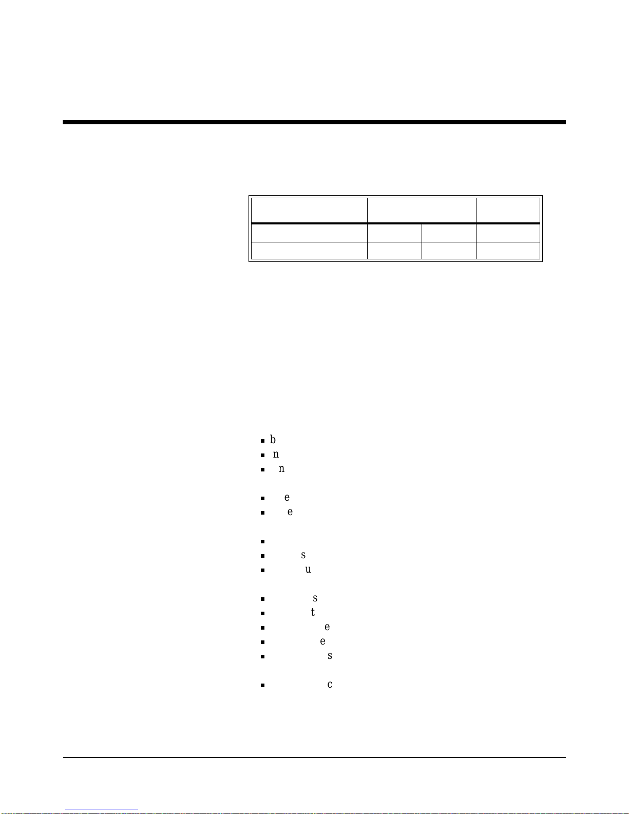
This chapter contains general information on the operating features of the
E8402A and E8404A C-Size VXI mainframes. The follo wing table lists t he
major differences between these two mainframes:
Unless otherwise specifically noted, descriptions in this manual relate to
both VXI mainframes. The designation HP E840xA refers to both
mainframes. Chapter 2 provides a complete Enhanced Monitor description.
Product Overview
The HP E840xA VXI mainframes are designed in full compliance with
VXIbus specification revision 1.4, VXIpl ug&play specificati on VPP-8, and
VMEbus system specification revision C.1. Additional features of the HP
E840xA mainframes include:
•Mainframe monitori ng of:
n
backplane voltage conditions
n
individual slot and power supply temperatures
n
fan and impeller operation
•State of the art cooling technology:
n
quiet, variable speed power supply fan and backplane impeller
n
increased static pres sur e
•Front panel Diagnostic Connector for:
n
power supply voltage measurements
n
power supply and backplane temperature measurements
n
power supply fan and backplane impeller verification
•Color Graphical Enhanced Monitor Display:
n
Help messages localized in English, French, German, Spanish
n
Stripcharts and Histograms for easy diagnostics
n
Three Temperature sen sors per mainframe slot
n
Display of each power supply voltage or current
n
User text messages
•Easy maintenance:
n
rear panel access to power suppl y, power supply fan, and cooling
impeller for either bench or rack mount operation.
Power Supply
500 W 1000 W
Enhanced
Monitor
HP E8402A Mainframe
ää
HP E8404A Mainframe
ää
Page 16

18 Getting Started Chapter 1
Preparing Yo ur VXI System for Use
The HP E840xA mainframes are sh ipped from the factor y ready to use. This
section describes important mainframe installation procedures.
AC Power
Requirements
The HP E840xA mainframes can be operated at line voltages of
90 VAC to 264 VAC, and line frequencies of 47 Hz to 66 Hz. The
mainframe can also operate at 360 Hz to 440 Hz with line voltages of
90 VAC to 132 VAC.
The mainframes ship wi th a power cord and wit h a fast blow fuse in sta ll ed.
The fuse is suitable for all line voltages. The fuse is not user replaceable.
Refer to “Replacement Power Cords” on page 215 for additional
information on E840xA p ower cor ds and o n fuse r eplac ement. Appendi x A
contains complete input power specifications.
WARNING The power cord is the only way to disconnect the mainframe
from AC power and, therefore, it must be accessible to the
operator at all times. When the HP E840xA mainframes are
mounted in a system cabinet, the power cord need not be
accessible since the cabinet must have its own disconnect
device.
Positioning th e
Mainframe for
Adequate Cooling
VXI instruments are c ooled by air drawn through the back of the mainfra me
and exhausted out the sides . The po wer supply is cooled by air drawn fro m
the right side (facing t he mainframe) and exhausted out the lef t si de. When
placing the mainframe on a work bench or if the mainframe is rack mounted,
provide at least a one inch clear ance at the back a nd sides to all ow for proper
air flow.
Air filters are not necessary on these mainf ra mes. However, an optional ai r
filter kit (mainfr ame opti on 938 or HP E8401-80 938) is avail able f or use i n
harsh environments. The airflow is restricted less than 10% with the air filter
installed. Refer to “HP E840xA Air Filter Kit” on page 248 for installation
information.
Page 17
Getting Started 19Chapter 1
Connecting the
Mainframe to a
Permanent Earth
Ground
The mainframe must be connected to a permanent earth ground for line
frequencies greater than 66 Hz. This connection is made on the back of the
mainframe:
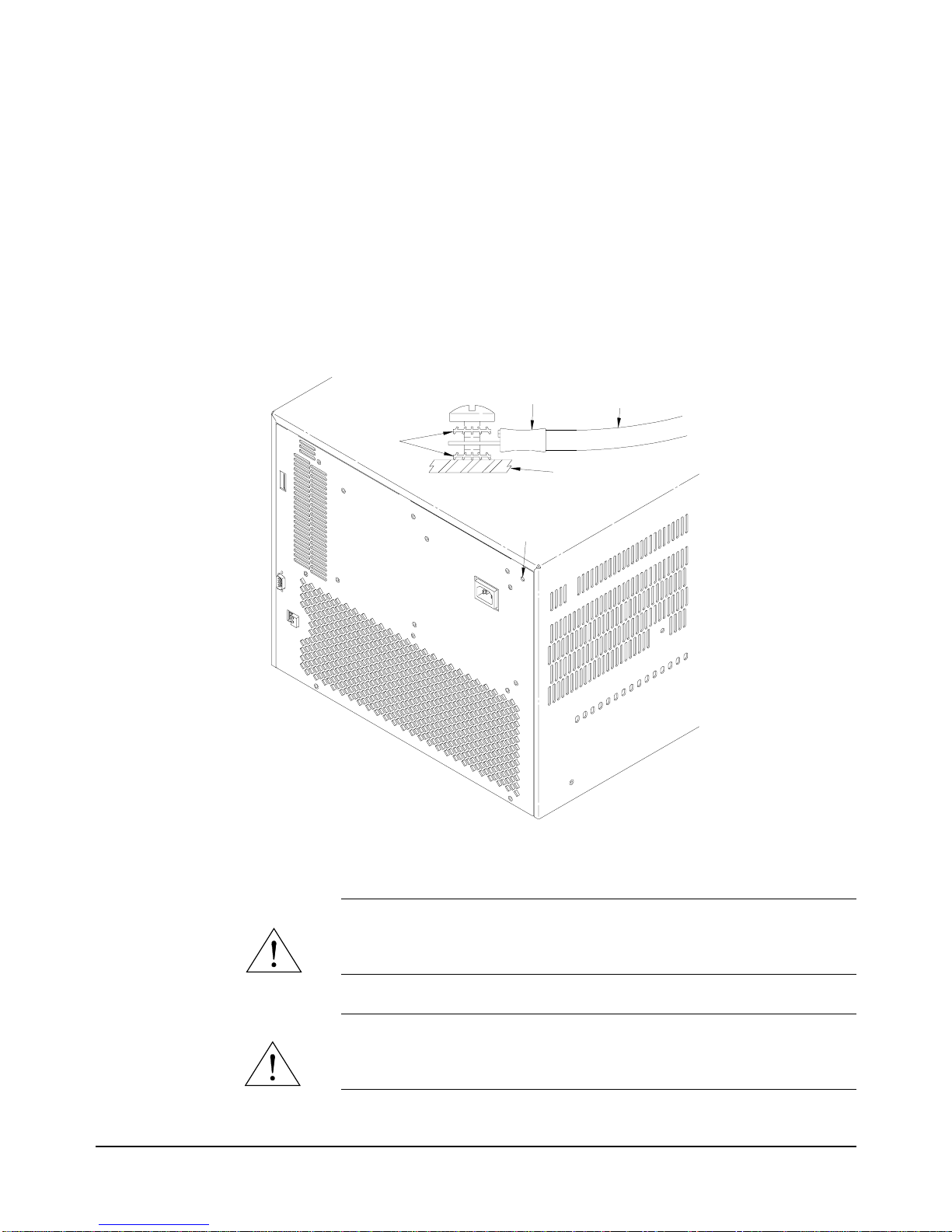
1. Connect a 16 AWG (1.3 mm or larger) wire to the PEM nut sho wn in
Figure 1-1. The wire must be green with a yellow stripe, or bare (no
insulation). Use a m4 x 10 s crew, grounding lug, and toothed wash ers
(or toothed lug) as shown in the Figure.
2. Attach the other end of the wire to a permanent earth ground using
toothed washers or a toothed lug.
WARNING For protection from electrical shock when operating at
frequencies greater than 66 Hz, connect the chassis ground
terminal to permanent earth ground.
AVERTISSEMENT Risque de Choch èlectrique. Si la frèquence du secteur est
supèrieure à 66 Hz, relier la borne de masse du chassis à une
prise de terre fixe.
Figure 1-1. Connecting an HP E840xA Mainframe to a Permanent Earth Ground
(HP E8404 shown, HP E8402 is similar)
TOOTHED
WASHERS
BACK COVER
WIRE LUG
GREEN WIRE
WITH YELLOW
STRIPE
PERMANENT EARTH
GROUND CONNECTION
LOCATION
Page 18

20 Getting Started Chapter 1
Installing VXI Instru ments
The HP E840xA mainframes have 13 slots labeled 0 through 12. Any VXI
instrument can be installed in any slot; however, slot 0 is reserved for
devices capable of providing the system’s slot 0 functionality. This
functionali ty includes:
•locating instruments installed in the mainframe
•managing (arbitrating) data flow across the backplane
•providing the system clock (SYSCLK - 16 MHz)
Examples of these devices are the HP E1406 Command Module and
embedded controllers such as the HP E623x series VXI Pentium PCs, the
HP RADEPC7B PC, and the HP E1497/E1498 V743 controllers.
Multiple instruments which combine to create a virtual instrument (e.g. a
scanning multimeter), and i nstruments which access th e backplane local bus
should be installed in adjacent slots.
1. To prevent damage to the VXI instruments, turn o ff the mainframe
prior to installing the instruments.
2. Insert the instrument in to the mainframe by aligning the instrument
with the card guides inside the mainframe. Slowly push the
instrument in to th e slot until it sea ts in the backplane connectors. The
front panel of the instrument should be even with the front edges of
the mainfram e.
3. Tighten the retaining screws on the top and bottom of the module.
WARNING All instruments withi n the VXI mainf rame are grounded through
the mainframe chassis. During insta llation, tighten the
instrument’ s retaining screws to secure the instrument to the
mainframe and to make the ground connection.
Page 19
Getting Started 21Chapter 1
Installing C-Size
Instruments
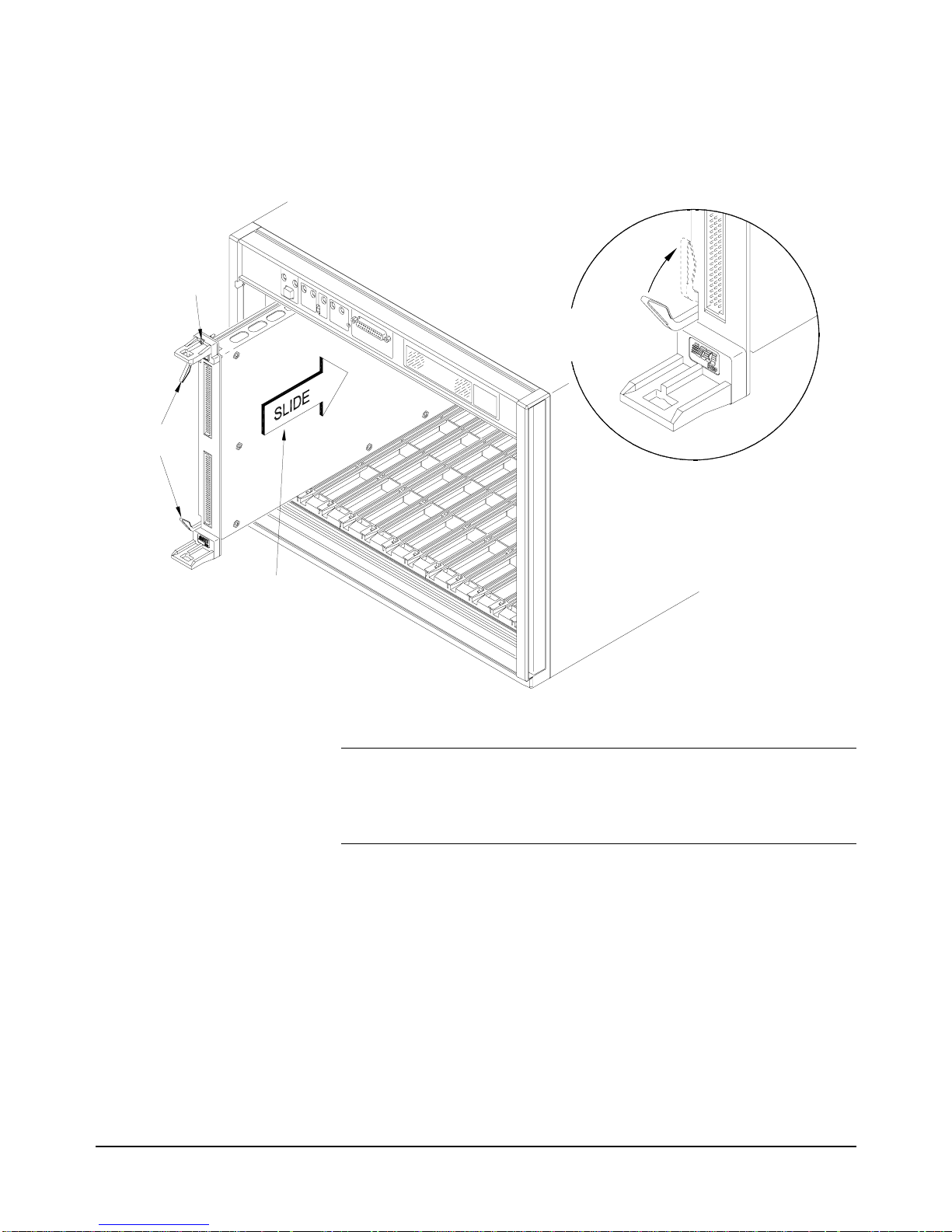
Figure 1-2 shows the installation of C-Size instruments.
WARNING All instruments withi n the VXI mainf rame are grounded through
the mainframe chassis. During insta llation, tighten the
instrument’ s retaining screws to secure the instrument to the
mainframe and to make the ground connection.
Figure 1-2. Installing C-Size Instruments in the HP E840xA Mainframe
Retaining
Screws
Extraction
Levers
Slide the module
into the mainframe
until it plugs into the
backplane connectors
Seat the module by
pushing in the
extraction levers
Page 20
22 Getting Started Chapter 1
Installing A- and
B-Size Instruments
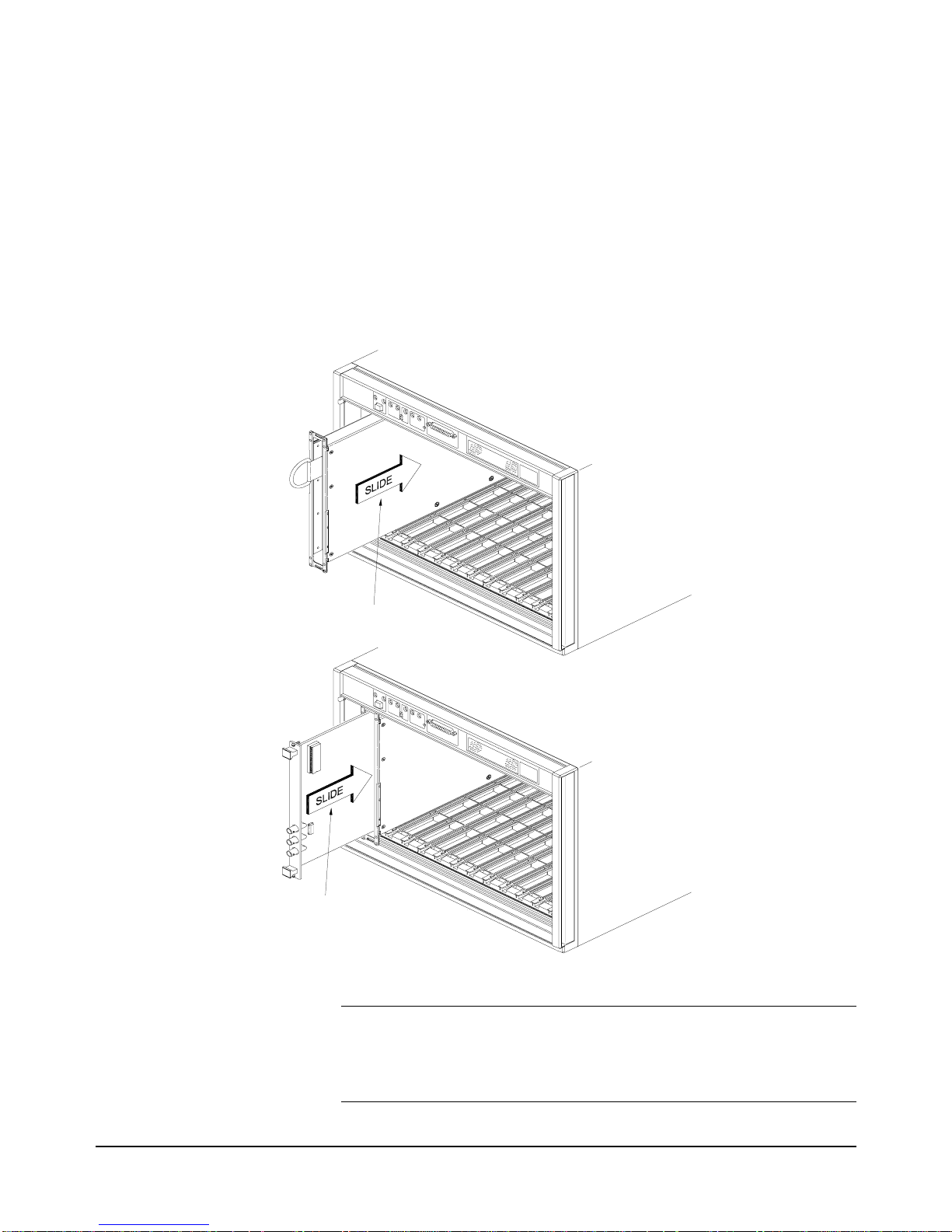
Figure 1-3 shows the installation of A- and B-size instruments.
•HP E1403B A/B-size Module Carrier extends the P1 connector on
the VXIbus backplane and mounts the (A/B-size) modules flush with
C-size modules. This carrier is recommended for Hewlett-Packard
B-size, slave-only devices which have the P1 connector.
•HP E1407A A/B Module Carrier extends the P1and P2 connectors
on the VXIbus backplane. This carrier is recommended for B-Size,
slave-only devices which have the P1/P2 connectors.
WARNING All instruments withi n the VXI mainf rame are grounded through
the mainframe chassis. During insta llation, tighten the
instrument’ s retaining screws to secure the instrument to the
mainframe and to make the ground connection.
Figure 1-3. Installing A- and B-Size Instruments in the HP E840xA Mainframe
Slide the Adapter M odule into
the Mainfram e until it plugs into
the Backplane C onnector
Connects
the Adapter Module until it
Slide the B-Size M odule into
Page 21
Getting Started 23Chapter 1
Configuring Your Mainframe
Setting the
Enhanced Monitor
VXI Logical
Address
The Enhanced Monitor of the HP E8402 and E8404 mainframe s plu gs in to
the VXI backplane f rom the rear of the mainframe. It does n ot occupy a slot
in the mainframe or tie-up th e MODID line. The enhanced monitor is a
message-based device, allowing easy communication over the VXI bus (f or
example, through a command module or embedded controller) or a standard
RS-232 interface. The enhanced monitor does require a VXIbus address;
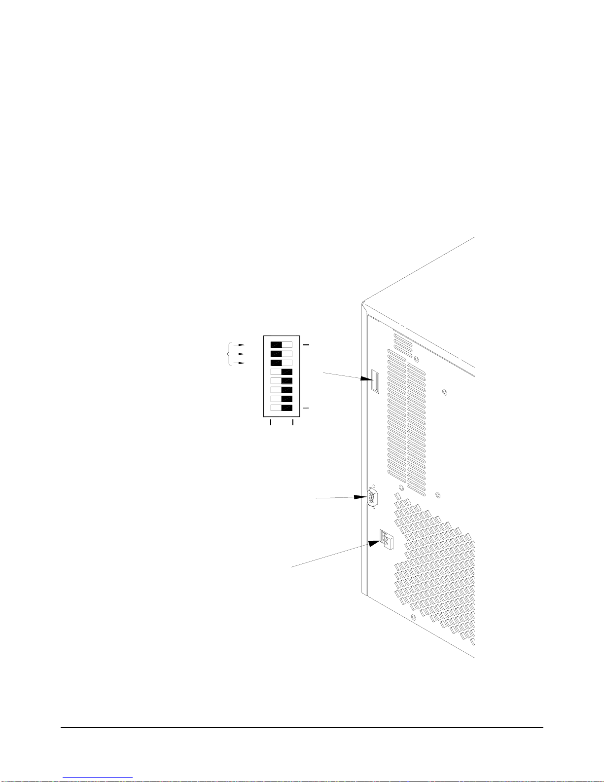
224 is the factory default. Figure 1-4 shows the rear panel of the HP
E8402/E8404 VXI mainframe with the Enhanced Monitor logical address
switches and RS-232 interface.
Figure 1-4. Rear panel of the HP E8402 and E8404 VXI Mainframes
10
128
64
32
16
8
4
2
1
7
0
LADDR
32+64+128=224
CLOSED = Switch Set to 1 (ON)
OPEN = Switch Set to 0 (OFF)
RS-232
+5V EXT
Page 22

24 Getting Started Chapter 1
RS-232 Interface The RS-232 interface on the r ear panel of the Enhanced Moni tor mainframes
(HP E8402 and E8404) can be used to control the E nhanced Monitor f rom a
computer or a terminal.
Refer to Chapter 3 for RS-232 programming information. The
SYSTem:COMMunicate:SERial ... commands set and/or modify the
configuration of the Enhanced Monitor’s serial interface. Serial
communication commands take effect after the end of the program messa ge
containing the command(s).
Default RS-232 parameters are:
•Baud: 9600
•Bits: 8
•Parity: None
•Stop bits: 1
•DTR/RTS: On
•Pace: XON
•Echo: On
•ERES: On
•Line buffer: On
Note If you use the Enhanced Monitor RS-232 interface (located on the
back of the mainframe) while the mainframe is in the standby mode,
you must supply an external +5Vdc to the +5VEXT connector
(located near the RS-232 interface). If you use the RS-232 interface
while the mainframe is powered on, you do not need to provide the
external +5Vdc.
External +5V Supply The External +5V supply is for powe ring the Enhanced Mon itor (includ ing
the RS-232 in terface) while the mainframe is powered down (standby
mode). This requires a stable 5 vol t supply c apable of 1.5A a mps maximum
(500mA typical, refer to speci ficati ons in Appendix A). Refer to Figure 1-4.
Page 23
Getting Started 25Chapter 1
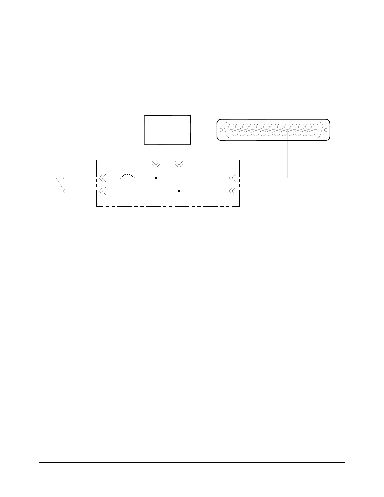
Using the Remote
Power-On Pins
The remote power-on pins ( pins 5 and 18) of the Diagn ostic Connector allow
you to turn the mainf rame on and off without using t he front panel On/Stdby
switch. With the On/ Stdby switch in the Stdby (off ) position, co nnecting pin
5 to pin 18 on the diagnostic connector turns the mainframe on.
Disconnecting pin 5 from pin 18 turns the mainframe off.
Note Pin 18 is ground in the HP E8402 and E8404 mainframes. Therefore,
you only need to ground pin 5 to turn the mainframe on.
Figure 1-5. Remote Standby Switch Wiring.
13
25 18
5
14
1
Power
Supply
Front
Panel
Switch
BACKPLANE
5
18
SUB D
CONNECTOR
HP E840X
Page 24
26 Getting Started Chapter 1
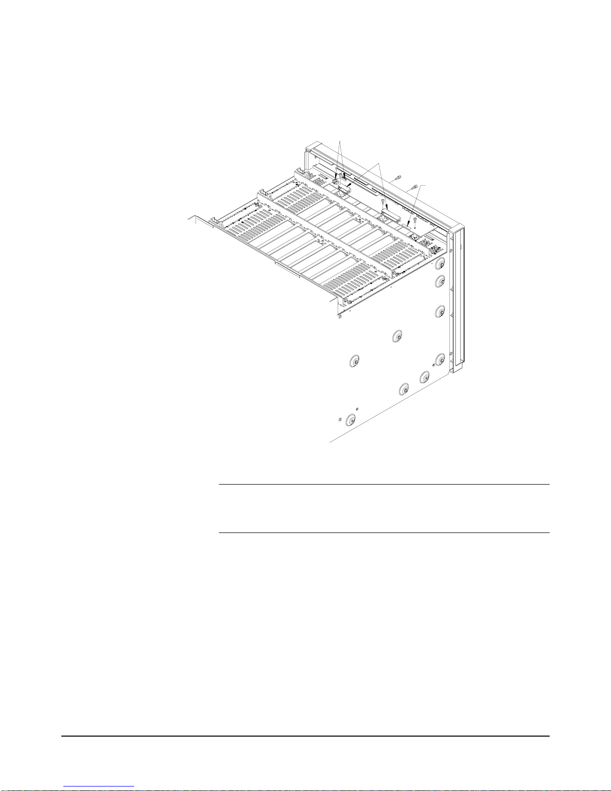
Disabling the
On/Stdby Switch
The front panel On/Stdby s witch is disa bled by removing surface mount 0Ω
resistor located on the front monitor board (see Figure 1-6). The resistor is
labeled:
REM PWR JUMPER.
Caution After removing the 0
Ω
resistor, heat damage may prevent the
resistor from being re-inst alled to re-enable the On/Stdby
switch.
To access the Monitor Display Board and resistor:
1. Turn off the mainframe and remove the power cord.
2. Remove the mainframe cove r by r emoving the 10 m3x6 fl at head t orx
screws.
3. Remove the 0Ω resistor by heating both sides simultaneously with
soldering irons. Separate the resistor from the board by gently
pressing the tips of the soldering irons together.
4. Save the resistor in order to re-enable the On/Stdby switch. Again,
heat damage may prevent the resistor from being re-installed.
Figure 1-6. Disabling the On/Stdby Switch
Location of
Resistor
Unplug
Unplug
Page 25

Getting Started 27Chapter 1
Mainframe Options and Accessories
Table 1-1. HP E840xA VXI Mainframes options and accessories
Description Option Number Product
Number
Cable Tray Kit Option 914 HP E8400-80914
Tinted Acrylic Door Kit Option 915 HP E8400-80915
Backplane Connector Shields Option 918 HP E8400-80918
Intermodule Chassis Shield Kit N/A HP E8400-80919
Standard Rack Mount Adapter Kit Option 923 HP E8400-80923
Flush Rack Mount Kit Option 924 HP E8400-80924
VXIplug&play (VPP-8) Compatible Rack Mount Kit Option 925 HP E8400-80925
Air Filter Accessory Kit Option 938 HP E8400-80938
Support Rail for Standard Rack Mount Adapter or Flush Rack Mount
Kit
N/A HP E3664A
Support Rail for VXIplug&play (VPP-8) Compatible Rack Mount Kit N/A HP E3663A
Rack Slide Kit for Standard Adapter Kit or VXIplug&play (VPP-8)
Compatible Rack Mount Kit
N/A HP 1494-0411
Page 26

28 Getting Started Chapter 1
Page 27

Using the Enhanced Monitor 29Chapter 2
Chapter 2
Using the Enhanced Monitor
The Enhanced Monitor on the front panels of the HP 840xA mainframes
allow you to monitor power supply voltages, mainframe temperatures, fan
operation, and backplane activity. Figure 2-1 shows the mainframe front
panel.
The enhanced monitor provides features such as:
• Monitoring the mainframe operating status including: blower status,
slot temperatures, an d power supply voltage s, cur re nt, and power. The
Enhanced Monitor generates a warning if any of these parameters
exceed limits. Refer to Chapter 3 for programming details.
• User-definable temperature limits for indi vidual slots; if the limit is
exceeded, a beeper sounds, LEDs flash, and the display shows the
warning condition.
• Storing a history of power supply voltages, currents, and power; slot
temperatures; fan speeds; events such as mainframe power cycled
on/off, etc.
In addition, you can:
• Perform internal Enhanced Monitor Self Tests. These verify its fans
and its ability to measure the slot temperatures and power supply
voltages and currents, etc.
• Set and query Enhanced Monitor system parameters. The Enhanced
Monitor functions are programmable through either the system
commander (command module or embedded controller) or via an
RS-232 port on the back of the mainframe.
• Write user text messages to the front panel display. This is useful for
communicating with an operator.
Page 28
30 Using the Enhanced Monitor Chapter 2
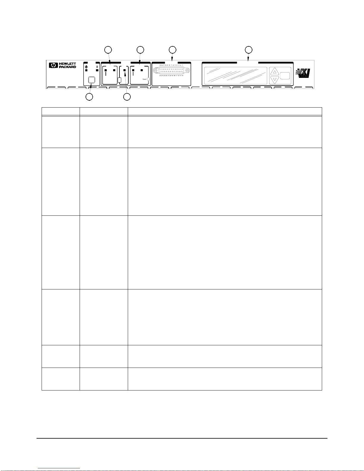
Figure 2-1. HP E8402A and E8404A Enhanced Monitoring Front Panel
0 121110123456789
E8401A
VXI MAINFRAME
Power Status Diagnostic
Stdby On Temp
Power
Full
Var
Activity
SYSFAIL
System Fans Backplane
2
1 3
4 6
Enhanced Monitor
Enter
5
Supply
Section Indicator / Switch Description
Power
On Indicator
Standby Indicator
Green - the mainframe is turned on.
Amber - the mainframe is in standby mode; no power is applied to VXI modules.
Both Indicators Off - there is no power applied to the mainframe.
ô
System
Power Supply
Indicator
Temp Indicator
Green - all voltages, currents, and power supply temperatures are within expected
operating ranges.
Flashing Amber - one or more power supply measurements are out of limit.
Green - all the individual slot temperatures and ambient temperatures are within normal
operating ranges.
Flashing Amber - one or more slot temperatures or the ambient temperature has
exceeded specified limits.
í
Fans
Fan Switch
Fans Indicator
Full - the power supply and mainframe cooling fans are operating at full speed.
Var(iable) - the power supply and mainframe cooling fans are providing user-specified
cooling level. Fan speed is a function of the power supply temperature, ambient
temperature, and individual slot temperatures. Fan speeds operate at the lowest possible
speed to maintain user-specified cooling level.
Green - the power supply and mainframe cooling fans are operating within expected
ranges.
Flashing Amber - the power supply fan or the mainframe cooling fan is not operating
within expected ranges.
÷
Backplane
Activity Indicator
SYSFAIL Indicator
Reset Switch
Green - there is communication between instruments across the backplane. Off - there is
no communication between instruments on the backplane.
Amber - one or more instruments has asserted its SYSFAIL line due to a power-on
initialization failure, self-test failure, or hardware failure. SYSFAIL is asserted momentarily
at power on and during a system reset.
Pressing the reset button asserts the SYSRESET* line on the VXI backplane. When low,
this line resets the VXI system; all VXI instruments are rest to their power-on state.
û
Diagnostic
Connector
Refer to “Diagnostic Connector” on page 42.
ø
Display and
Keypad
Refer to “Using the Enhanced Monitor” on page 31
Page 29

Using the Enhanced Monitor 31Chapter 2
Using the Enhanced Monitor
The Enhanced Monitor is a separate PC board that plugs into the VXI
backplane from the rear of the mainframe. In this way it does not occupy a
user slot on the front of the mainframe. The Enhanced Monitor uses a
standard-defined P 1 Connector but a uni quely-defi ned P2 Connector. It is a
message-based, slave-only VXI interface card, complete with its own VXI
logical address. Refer to Chapter 3 of this manual for SCPI programming
information. This se ct ion pro vid es gener al in form ation abou t the Enh anced
Monitor.
•RS-232 Interface supports communication with a terminal or
computer for remote monitor in g pur pose s onl y. Refer to Chapter 3 for
SCPI programming information.
-- All SCPI command are supported by the RS-232 interface.
-- The RS-232 interface is set-up only through SCPI commands.
Settings are stored in non-volatile memory. Factory defaults are:
9600 Baud, 8 bits, No Parity, 1 Stop Bit, DTR/RTS On, XON
Pacing.
•Ambient Tempe ratur e Monitor (±2 °C). The sensor is locat ed in the
intake air stream path just above the mainframe impeller.
-- A user-defined limit can be set, de fault is 55
°C.
-- Limit is restored from non-volatile memory at power-on.
-- When the limit is exceeded, the monitor gen erates a warning on the
display, sets a status bit, the temperature LED flashes, and the
beeper sounds (if enabled).
•Power Supply Temperature Monitor (±2 °C). The sensor is located
under a power supply transformer . Th e re adi ng i s i ndi cat iv e of over al l
power supply loading.
-- If the temperature exceeds an expected level, the monitor generates
a warning on the display, sets a status bit, the power supply LED
flashes, and the beeper sounds (if enabled).
•Module Exhaust (Slot) Temperature Monitor (±2 °C). Three
sensors, front, middle, and rear are located above each slot.
-- Temperatures may be queried in actual
°C or as temperature rise
above ambient (in
°C).
-- User-definable limits can be set for the entire cardcage or on a
slot-by slot basis.
-- Limit may be set in actual temperature (default is +65
°C) and as
temperature rise above ambient (default is +15
°C).
-- Limits are restored from non-volatile RAM at power-on.
-- If a slot temperature exceeds the specified limit, the monitor
generates a warning on t he display, sets a status bit, the temperatur e
LED flashes, and the beeper sounds (if enabled).
Page 30

32 Using the Enhanced Monitor Chapter 2
•Voltage Monitor measures all seven power supply voltages (+5, ±12,
±24, -5.2V, and -2V).
-- Voltages outside of fixed limits (based on VXI specifications)
causes the mo nitor to generate a warning on the display, set a status
bit, the Power Supply LED flashes, and the beeper sounds (if
enabled).
•Current Monitor measures the current from all seven power supplies
(+5, ±12, ±24, -5.2V, and -2V).
-- Currents exceeding user-specified limits (defaults to mainframe
specifications +10%) cau ses the monito r to generate a warning on
the display, set a status bit, the Power Supply LED flashes, and the
beeper sounds (if enabled).
•Power Monitor calculates the total output power of the power supply
[Σ(V*I)].
-- Total output power exceeding user-specified limits (defaults to
mainframe power supply maximum) c aus es the moni tor t o ge ner at e
a warning on the display, set a status bit, the Power Supply LED
flashes, and the beeper sounds (if enabled).
•Backplane Activity Monitor monitors acti vit y on t he VXI ba ckpl ane.
-- The DS0 and DS1 backplane lines are monitored. Activity is
displayed through the front panel Activity LED. No warning is
associated with this activity.
-- SYSFAIL is also monitored. Assertion of SYSFAIL (by any VXI
module) is shown by the amber SYSFAIL LED on. It will not sound
the beeper or generate a warning on the display.
•Fan Monitor monitors the operation of the fans.
-- Fan speeds outside a fixed range generate a warning on the display,
sets a status bit, the FAN LED flashes, and the beeper sounds (if
enabled).
-- Fan level is returned as a percentage (%) of maximum speed.
•Fan Controller adjusts mainframe fan speed based on the power
supply, ambient, and individual slot temperatures. The fan can be set
to maximum or FULL speed by a front panel switch.
-- In the Variable mode, if the power supply temperature exceeds
an expected level, the fan speed increases to maximum.
-- In the Variable mode, if the ambient temperature exceeds +50
°C,
the fan speed increases to maximum.
-- In the Variable mode, if any VXI module exhaust temperature
approaches a user-defined limit, fan speed increases.
-- Otherwise, fan speeds operate at the lowest possible speed to
maintain user-specified cooling level.
•Time Monitor records:
-- Total hours of operation
-- Time-on since power on, last test, last calibration, last history reset.
-- Time remaini ng until the next maint enance. This time ca n be set and
queried by the user. A warning is generated w hen the timer reaches
0. Note: this is disabled as shipped from HP.
Page 31

Using the Enhanced Monitor 33Chapter 2
Using the Display The Enhanced Monitor display graphically portrays status information
about the mainframe. This i ncludes strip ch arts and histograms of fan speed,
slot and ambient temperature, and power supply voltage, and power.
The first time the mainframe is powered on, the display prompts you to
select a language; either English, German (Deutsch), French (Français), or
Spanish (Español). Use the arrow keys ju st to the right of the display to
highlight a language then pr ess the
Enter key. All display and he lp screens
will appear in the selected language.
Use the up/down arrow keys to hi ghlight a display item, the n press the
Enter
key to select that ite m. I n t he up per r igh t han d co rner of a ll d isp lays (exce pt
the language select ion display) is an arrow; selecting thi s arrow and pressin g
the
Enter key moves you back to the previous display. Some displays also
have a question mark (
?) in the upper right corner. Selecting the question
mark brings up a help screen descr ibing the dis play. Figure 2-2 shows three
typical displays and a help screen.
Menu Map Figure 2-3 shows a complete display menu map for the Enhanced Monitor.
Figure 2-2. Typical Displays for the HP E8402A and E8404A Enhanced Monitor
Use the UP/DOWN arrow keys to highlight a
Press the Enter Key to return to the
previous display.
menu item (in this case "Power Supply" is
highlighted). Press the Enter key to select it.
Use the UP/DOWN arrow keys to highlight a
menu item (in this case "Voltage" is
highlighted). Press the Enter key to select it.
This display shows the actual measured power
Mark. Highlight the Question Mark and press the
Enter key for a display description.
supply voltages. Use the UP/DOWN arrow keys
to highlight either the arrow or the Question
Page 32

34 Using the Enhanced Monitor Chapter 2
Figure 2-3. HP E8402 & E8404 Enhanced Monitor Display Menu Map
Power Supply
Voltage Limits
Current Stripchart
Power Histogram
+5V: 5.0V -24V: -24.0V
+12V: 12.0 V -5.2V: -5. 1 V
-12V: -12.0V -2V: -2.0V
+24V: 24.0V 5VStdby: 0.0V
+5V: 10.9A -24V: -1.2A
+12V: 1.8A -5.2V: -6.2A
-12V: -0.9A -2V: -2.3A
+24V: 1.3A
+5V: 54W -24V: 29W
+12V: 21W -5.2V: 32W
-12V: 10W -2V: 5W
+24V: 30W Total: 182W
+5V: 460W -24V: 360W
+12V: 180W -5.2V: 312W
-12V: 180W -2V: 60W
+24V: 360W Total: 1000W
Power Supply Strip Chart
+5V +24V -2V Total
+12V -24V 5VStdby
-12V -5.2V PS Temp
Power Supply Histogram
+5V +24V -2V Total
+12V -24V 5VStdby
-12V -5.2V PS Temp
?
?
?
?
MPSupply
PSVoltage
PSCurrent
PSPower
PSLimit
MPSStripchar
MPSHistogram
?
PSSTripchar[1..10]
?
PSHistogra[1..10]
Temperature
Status Histogram
Limits
Stripchart
°C R
M
Amb
F
29
slot 0 1 2 3 4 5 6 7 8 9 10 11 12
Temperature Stripchart
Slot 0 Slot 3 Slot 6 Slot 9 Slot12
Slot 1 Slot 4 Slot 7 Slot 10 Amb
Slot 2 Slot 5 Slot 8 Slot 11
?
?
MTEMperature
TSTatus
TLIMits
MTSTripchart
?
THIStogram[0..13]
?
TSTRipchart[0..13]
Temperature Histogram
Slot 0 Slot 3 Slot 6 Slot 9 Slot12
Slot 1 Slot 4 Slot 7 Slot 10 Amb
Slot 2 Slot 5 Slot 8 Slot 11
MTHistogram
Fans
Status
Stripchart
Histogram
Present Level of Fans: 65%
Main Fan Speed: 1498 RPM
Power Supply Fan Speed: 2214RPM
Power Supply Fan2 Speed: 2056RPM
?
?
?
MBLower
BSTatus
BSTripchart
BIHistogram
Select a Language
English Francais
Deutsch
Espanol
Mainframe Status
Power Supply System
Temperature Display
Fans History
LANGuage
MMAin
Note: the names under each display
refer to the parameter for the
DISPlay:WINDow command. Refer to the
DISPlay:WINDow command on page 58 for
additional information.
Page 33

Using the Enhanced Monitor 35Chapter 2
Figure 2-3. HP E8402 & E8404 Enhanced Monitor Display Menu Map (continued)
System
Log RS-232
Timer VXIBus
Beeper About
Hours since Power-On: 13
Cumulative Hours On: 16
Hours since last Cal: 16
Number of times powered on: 16
?
?
?
?
Maintenance Timer
Timer Interval Hours: Disabled
Hours Remaining: Disabled
Beeper State
Use Up/Down keys to change state
Beeper = On
Baud: 9600 Parity: None
Bits: 8 Pace: XON
Stop Bits: 1 Echo: On
RTS: Off
?
?
MSYStem
SLOG
STIMer
SBEeper
SRS232
VXI Message Based Servant
Interrupt Line: 1
Logical Address: 224
HP E8404A Revision A.01.00
1000W AC Supply
Serial Number: 0
Name: not set
?
?
Event Hour
Mainframe Powered Off 413
Temperature Alarm, Slot 3 250
Fan Alarm, Impeller 250
HQUEue
Display
Screen Saver
Contrast
Screen Saver
Turns Display off after 10 minutes
Use Up/Down keys to change state.
Screen Saver = Off
Display Contrast
Use the Up/Down keys to adjust
contrast, then press Enter.
MDISplay
DSSaver
DCONtrast
SVXI
SABout
Page 34

36 Using the Enhanced Monitor Chapter 2
Enhanced Monitor Fan Control
With the front panel fan swi tch in t he VAR posit ion, the Enhan ced monit or
controls the fan s peed based on sl ot temperature limits you spec ify. With the
fan switch in the FULL position, the fan operates at full speed.
Essentially, the Enhanced Monitor’s fan control has two contrasting
functions: 1) keep the VXI modules installed in the cardcage cool and 2)
operate as quietly as possible. These are somewhat conflicting goals because
to operate at it s quietest , the fan woul d have to be off and hen ce not keep the
modules cool. Alternately, at its coolest, the fans would have to be full on
and the airflow is not quiet. Therefore, the fan control algorithm is to keep
the mainframe as quiet as possible while cooling the VXI modules
adequately.
What is adequate cooling? You specify it through your selection of slot
temperatures. For example, if you specify slot 7 temperature to be
maintained within 15 °C of the ambient temperature, the fan controller
adjusts fan speed until the cooling air coming off slot 7 is just under 15 °C
above ambient. And it will keep it there, adjusting the fan speed as needed
to maintain that temperature rise no matter wh at the ambient temperature
might do. That way, the fan noise is at its lo west while maintaining
appropriate cooling.
Each slot is monit ored and compar ed to the specified slot temper ature limits
every two seconds. The slot closest to its limit is allowed to approach the
limit in order to keep the fan speed as low as p ossible.
If you want a cooler mainframe, lower the slot temperature limits. If you
want a quieter mainframe, raise the temperature limits. Just remember that
the Enhanced Monitor Fan Controller is very accurate; if you specified
30 °C rise above ambient, t he controller will maintain a limit just belo w
30 °C.
There is one excepti on. The power supply cooli ng overrides all other cooling
requirements. For example, you may specify a 30 °C limit for all slots, but
as you monitor the slot temperatures you notice that no slot is approaching
the limit. It is likely that the Enhanced Monitor is working to keep the power
supply adequately coo led. Power suppl y cooling re quirements a re primaril y
driven by the load place d on the powe r suppl y. It needs more cooling if it is
significantly loaded. So, if the fan controller stops dropping the fan speed
even though the slot temperatures are not close to the specified limits, it is
probably because the power supply cooling requirements are dominating.
Software Control of
Fan Speed
The SYSTem:BLOWer:STATe command (page 131) can chan ge the state of
the fans from VARiable to FULL at any time. When software control has set
the fans to FU LL, the fron t panel fan switch can be set to variable and the
fans will remain a t FULL. Software control can not put a mainfr ame with its
switch set to FULL into a variable fan state. FULL means that the fans will
run at full speed no matter what the conditi ons in th e mainfr ame. VARiable
means that the enhanc ed monitor sets the fan speed based on the temperature
conditions in the mainframe and the temperature limits set by the user.
Page 35

Using the Enhanced Monitor 37Chapter 2
Setting Enhanced Monitor Limits
The HP E840x Enhanced Monitor has seve ral l imits that a ffect when i t wil l
issue warnings. Each limit should be selected based on the VXI modules
installed in the mainframe.
Temperat ure Limits The Enhanced Monitor monitors two types of temperature limits. First are
the "Delta slot temperature limits" whose primary function is to pass your
specified temperature limits to the Fan Controller (refer to “Enhanced
Monitor Fan Control” on page 36). If these limits are not maintained, a
warning is issued. The default value is 15 °C rise above ambient; this is a
compromise between cooling and noise. Check the specifications of your
installed VXI modules to determine sen sitivity to temperature variati on. Y ou
may need to specify a smaller delta slot temperature for some modules.
Second are the absol ute te mperatu re limi ts, for bo th indivi dual sl ots and th e
ambient temperature. These guard t he top end o f the accep table temper ature
spectrum and generate warnings if exceeded. The default values are
generally acceptable to most VXI modules; but you should verify the
temperature ratings for all VXI modules installed in the mainframe and set
the slot’s absolute temperature limit accordin gly. For exampl e, many
modules are specified for a temperature range of 0 to 55 °C and assume a
10 °C rise to occur in operation. Therefore, their absolute temperature is
safely 65 °C (the default). But, if a VXI module is only ra ted to 45 °C (and
assumes a 10 °C rise) t hen its slot shoul d have an absolu te temperatur e limit
of 55 °C. You might set the limit lower for earlier warning.
Use the
STATus:QUEStionable:TEMPerature:LIMit? command (page 114)
to set temperature limit s, bo th ambi ent and de lt a sl ot t emper at ure s. Use the
STATus:QUESTionable:TEMPerature:LEVEL? (page 113) to determine the
actual threshold when an over-temperature warning will sound.
Current and Power
Limits
By default, the En hanced Monitor pro vides power suppl y current and power
limit warnings only whe n the power supply i s exceedin g it s capacit y. But it
is unlikely that all seven supplies will be used at maximum capacity.
Consequently, this warning is generally too late for most applications. For
example, the +5V supply in the HP E8404 is capable of providin g up to 90A
(peak current, refer to Appendix A). It is therefore capable of delivering the
regulated voltage into nearly a dead short -- 0.06Ω. For this reason, you
should specify current and power limits to reflect the act ual needs of the VXI
modules insta lled in the main frame. Then a warning is gen erated in
sufficient time to correct a problem.
To set current limit s, calculate t he worst case current need ed on each suppl y
for your application, add 10%, and set your current limit to this value.
Alternately, allow your system to operate normally for a time, query the
maximum values measured by the Enhanced Monitor’s history subsystem,
and set the current limit to a comfortable margin above this maximum. Do
this for each of the seven VXI suppl ies an d for the to tal power va lue. In this
way, the Enhanced Monitor c an issue a warning when a module beg ins using
more power than normal. Use the
STATus:QUEStionable:CURRent:LIMit
command (page 105) to set current limits, and STAT:QUES:POW:LIM to
set the total power limit.
Page 36

38 Using the Enhanced Monitor Chapter 2
Handling Warnings With the limits set, th e mainframe will beep i f a limit is exceeded. Howeve r,
you need to include ex ception pr ocedures in your co mputer prog ram so that
the program can handle the warnings. To do this, you need to enable the
Enhanced Monitor’s Status Subsystem to interrupt the computer when a
warning occurs. Refer to Chapter 3, “Example 2: Setting up the Mainframe”
on page 50, for a program example demonstrating this procedure.
Save The Limits Once you have specified temperature and voltage/power limits for your
mainframe, remember to save the limits in non-volatile memory. Otherwise,
you will start again after a mainframe power-down or reset. Use the
SYSTem:NVSave command (page 150) to save the values in non-volatile
memory.
Enhanced Monitor Measurement Cycles
The HP E8402 and E8404 Enhanced Monitor monitors over 80 signals
throughout the mainframe every two seconds. These measurements are fed
to the display, the Status Subsystem (for warnings), the History Subsystem
(for storage), and the Fan Controller. The display shows the measurements
pertinent to the screen displayed, updated every two seconds. The Status
Subsystem sets status bits in the condition registers, updated every two
seconds. The History Subsystem calculates minimums, maximums, and
histogram values, updated every two seconds. However, the Enhanced
Monitor stores its measu rements in the Trac e Subsystem only once e very 10
seconds.
During the measurement cycle, the Measuring bit in the Operational Status
Condition Register is set and then cleared. This allows you to synchronize
with the measuring cycle if you want to.
Page 37

Using the Enhanced Monitor 39Chapter 2
Using the History Queue
The HP E840x Enhanced Monitor provides many history feature records
such as: minimum and maximum values, histograms, operating times, and
event logs. As you be gin to use t he mainframe, t he history feat ures won’t b e
of much use -- very little has happened, th ere is no his tory to re cord. But as
time passes, the histor y features can provide valuable insights int o the trends
of your test system. Then, when you encounter a problem in your tests
system, you have a record of events to evaluate:
-- What type of environment has the module experienced?
-- What events led up to the failure?
-- What changes from one test system to another?
Over time, familiarity with the problems of one particular test system may
lead to predictive knowledge about the system. Then, by watching those
predictive events using the history feature, you can prevent problems.
HISTory Queue One of the history features is h istory queue – a list of events that occurr ed in
the mainframe. History event s are re corded with the op erati ng time th at the
event took place (the operating time is the number of seconds since the
mainframe was manufactured). The history queue is available through the
display; operating time is displayed in hours. Operating Events are shown
with the most rece nt displayed first, e arliest events dis played last. Figure 2-4
shows an example history display.
To access the history queue, select
History from the Mainframe Statu s
display or execute the command:
DISP:WIND HQU. Use the Up/Down
arrow keys to page up and down the list (Up/Down arrows appear in the
display only when additional data is available) four events at a time.
Figure 2-4. Example History Queue Display
Down arrow indicates
more data is available.
Use Up/Down keys to
scroll through display.
Page 38

40 Using the Enhanced Monitor Chapter 2
RS-232 Programming
The RS-232 port on the Enhanced Monitor is primarily a debug port,
designed for use with a dumb terminal or terminal emulator program on a
PC. This allows you to execute SCPI commands directly without an
application progra m and to moni tor a ny err ors i n the erro r q ueue ( inclu ding
those generated throug h the VXI interface programming). It also al lows you
to query the Enhanced Monitor while the mainframe is in standby if an
external +5VDC is appli ed to the 5V EXT te rminals. The RS-2 32 port is th e
only possible source for temperature calibration since the mainframe must
be empty for temperature calibration.
Windows 95
®
and Windows NT® provide a terminal emulator program
called Terminal or HyperTeminal. These applets provide a convenient
method of using the Enhanced Monitor. Use an app ropriat e nine-pin female
to nine-pin female RS-232 cable (such as the HP 24542U) for connection
between the PC and the Enhanced Mon itor. Config ure the Ter minal setti ngs
for generic TTY, and the communication settings to match those of the
Enhanced Monitor.
Default RS-232 parameters are:
•Baud: 9600
•Bits: 8
•Parity: None
•Stop bits: 1
•DTR/RTS: On
•Pace: XON
•Echo: On
•ERES: On
•Line buffer: On
Refer to Chapter 3 for RS-232 programming information. The
SYSTem:COMMunicate:SERial ... commands set and/or modify the
configuration of the Enhanced Monitor’s serial interface. Serial
communication commands take effect after the end of the program messa ge
containing the command(s).
Note If you use the Enhanced Monitor RS-232 port (located on the back of
the mainframe) while the mainframe is in the standby mode, you
must supply an external +5Vdc to the +5VEXT connector (located
near the RS-232 port). If you use the RS-232 port while the
mainframe is powered on, you do not need to provide the external
+5Vdc.
Page 39

Using the Enhanced Monitor 41Chapter 2
The Enhanced Monitor also provides several short cuts, primarily for
terminal use:
Backspace In TERMinal mode, a backspace means "back-up." It
becomes a space in RAW mode.
Ctrl-R In TERMinal mode, this provides a "recall last
command string" feature. It is ignored in RAW mode
Ctrl-T In either TERMinal or RAW mode, Ctrl-T performs a
SYSTem:COMMunication:PRESet:TERMinal
command. This puts the Enhanced Monitor into its
terminal mode at whatever baud rate presently set.
Ctrl-C In either TERMinal or RAW mode, Ctrl-C performs the
equivalent of a Device Clear. It can interrupt a
command that is taking too long to execute and makes
it possible to reset the Enh anced Monito r (*RST).
Be sure to turn off the Terminal applet’s use of t he control keys for Windows
use if you want to use these short cuts.
The RS-232 port can be used to program t he Enhance d Monitor . Be caref ul
when programming this way though. Remember that you have to turn off
terminal features like echo and immediate error. Do not try to use both the
VXI programming interface and the RS-232 port at the same time. They
both access the same error queue and status registers.
You should avoid changing RS-232 port parameters through the RS-232
port. It will work but you must be careful otherwise you may lose
communications. Intersperse your commands with queries. This will help
you stay synchronized with the port. If y ou reattach a terminal after using a
computer and see no character echo , Ctrl-T should return the port to te rminal
mode.
Page 40

42 Using the Enhanced Monitor Chapter 2
Diagnostic Connector
The 25-pin Sub-D diagnostic connector provides access to backplane
voltages, power supply and backp lane temperatures, and out put signals. The
pins are described in Table 1-2.
Table 2-1. Diagnostic Connector Pin Descriptions
Pin # Function Description
1 +5 VM +5V backplane voltage monitor (high impedance). (+4.875 Vdc to +5.125 Vdc)
2 -12 VM -12V backplane voltage monitor (high impedance). (-12.6 Vdc to -11.64 Vdc)
3 -24 VM -24V backplane voltage monitor (high impedance). (-25.2 Vdc to -23.28 Vdc)
4 -2 VM -2V backplane voltage monitor (high impedance). (-2.1 Vdc to -1.9 Vdc)
5 Rem On Remote power on. See “Using the Remote Power-on Pins.”
6 +5 VC +5 VDC source output (1A maximum).
7 +12 VC +12 VDC source output (1A maximum).
8 +5 V Stdby Input for +5V STDBY (1A maximum for pins 8 and 21 combined).
9 GND Chassis ground.
10 SysReset * TTL low-true input signal causes system reset, output indicates system reset.
NOTE: If you use this pin you must not violate VXI specifications.
11 PS Temp Output voltage proportional to power supply temperature (0 VDC at 0 °C, with a rise of
10 mV per degree centigrade).
12 Ref T emp Output voltage proportional to backplane temperature (0 VDC at 0 °C, with a rise of 10 mV
per degree centigrade). A function of the ambient temperature and load.
At no load, T
ref
~ 2 °C + ambient. At full load and high fan speed,
T
ref
~ 14 °C + ambient. At full load and low fan speed, T
ref
~ 20 °C + ambient.
13 Fans OK * TTL low-true output voltage indicates power supply and backplane cooling fans are
operating.
14 +12 VM +12V backplane voltage monitor (high impedance). (+11.64 Vdc to +12.6 Vdc)
15 +24 VM +24V backplane voltage monitor (high impedance). (+23.28 Vdc to +25.2 Vdc)
16 -5.2 VM -5.2V backplane voltage monitor (high impedance). (-5.46 Vdc to -5.044 Vdc)
17 GND Chassis ground.
18 REM Rtn Remote power switch return. See “Using the Remote Power-On Pins.”.
19 V OK * TTL low-true output voltage indicating the +5V, ± 12V, ± 24V, -5.2V, and -2V power supply
voltages are within ± 8% of its allowed variation.
20 GND Chassis ground.
21 +5 V Stdby Input for +5V STDBY (1A maximum for pins 8 and 21 combined).
22 GND Chassis ground.
23 ACFAIL* TTL low-true output asserted by the mainframe power monitor at power down or whenever
a loss of power is detected.
24 GND Chassis ground.
25 RSV
Reserved. Used for Timer Verification; refer to Chapter 4.
1
14
15
2
3
4
5
16
17
6
7
8910
11
181920
2122
23
12
13
24
25
Page 41

Using the Enhanced Monitor 43Chapter 2
+5VC
(pin 6)
The +5 volt output allows you to power external TTL circuits if required.
The maximum current allowed from this supply is 1.0A
+12VC
(pin 7)
The +12 volt output all ows you t o power ex tern al cir cuits , charge a batt ery,
or power relays if requir ed. The maximum cur rent allowed fro m this supply
is 1.0A
+5V STDBY
(pins 8, 21)
This provides an input to the mainframe backplane for a +5V DC standby
power source. This may be from a separate battery or power supply. The
maximum current allowed is 1A to tal (pins 8 and 21 wired in para llel). It can
be used to power timers and other ci rcuits when the mainframe is in standby
mode.
SYSRESET*
(pin 10)
This pin provides an extension of the VXI backplane SYSRESET* signal
line. It can be used to monitor for SYSRESET* or to send a SYSRESET*
tot he backplane. Shorting this lin e to ground asser ts the SYSRESET* sig nal
to the system. If you u se an exte nsion cabl e from the Diagnosti c Connector ,
make certain that you do not violate the VXI backplane electrical
specifications (i .e. keep the cab le as short as possible, buffer the sig nal line,
etc.).
ACF AIL*
(pin 23)
This pin lets you monitor the ACFAIL* signal from the VXI backplane. If
you use an extension cable f rom the Diagnostic Connector , make certain that
you do not violate the VXI bac kplane elect rica l speci fica tions (i.e. ke ep th e
cable as short as possible, buffer the signal line, etc.).
Page 42

44 Using the Enhanced Monitor Chapter 2
Page 43

Programming the Enhanced Monitor 45
Chapter 3
Chapter 3
Programming the Enhanced Monitor
This chapter explains how to pr ogram th e enhanc ed mon itor o f the HP E8 402A and
E8404A VXI mainframes including:
• Complete C language program examples
• Complete SCPI Command Reference
• Complete IEEE 488.2 Common Command Reference
Understanding SCPI Commands
Commands are separated into two types: IEEE 488.2 Common Commands and SCPI
Commands.
Common
Command
Format
The IEEE 488.2 standard defines the Common commands that perform functions
like reset, self-test, status byte query, etc. Common commands are four or five
characters in length, always begin with the asterisk character (*), and may include
one or more parameters. The command keyword is separated from the first
parameter by a space character. Some examples of Common commands are shown
below:
*RST *ESR 32 *STB? *TST?
SCPI
Command
Format
The SCPI commands perform functions like setting parameters, making
measurements, and querying instrument states or retrieving data. A subsystem
command structure is a hierarchical structure that usually consists of a top level (or
root) command, one or more lower-level commands, and their parameters. The
following example shows part of a typical subsystem:
:DISPlay
[:WINDow] <dis play window>
[:WINDow]?
:TEXT
[:DATA] <
string
>
[:DATA]?
:DISPlay is the root command, [:WINDow] is a second-level command with
parameter.
Command
Separator
A colon (:) always separates one command from the next lower-level command as
shown in the example subsystem above.
Page 44

46 Programming the Enhanced Monitor
Chapter 3
Abbreviated
Commands
The command syntax shows most commands as a mixture of upper- and lowercase
letters. The uppercase letters indicate the abbreviated spelling for the command. For
shorter program lines, s end the abbreviated form. For bett er program readability, you
may send the entire command. The instrument will accept either the abbreviated
form or the entire comm and.
For example, if the co mmand sy ntax shows DISPlay, then DISP an d DISPLAY are
both acceptable forms. Other forms of DISPlay, such as DISPL or DISPLY will
generate an error. You may use upper- or lowercase letters. Therefore, DISPLAY,
display, and DiSpLaY are all acceptable.
Implied
Commands
Implied commands are those which appear in square brackets ([ ]) in the command
syntax. (Note that the brackets are not part of the command and are not sent to the
instrument.) Suppose you send a second-level command but do not send the
preceding implied command. In thi s case, t he instr ument ass umes you int end to use
the implied command and it responds as if you had sent it.
Examine the example subsystem above. The second level command [:WINDow] is
an implied command (indicated by square brackets []). You can use either form:
:DISPlay:WINDow <display window> or :DISPlay <display window>
Parameters Parameter Types. The following table contains explanations and examples of
parameter types you might see later in this chapter.
Optional Parameter: Parameters shown within square brackets ([ ]) are optional
parameters. (Note that the brackets are not part of the command and are not sent to
the instrument.) If you do not specify a value for an optional parameter, the
instrument chooses a default value.
Parameters separated by a vertical bar (|) indicate the only possible choices. For
example:
SYSTem:COMMunicate:SERial:CONTrol:RTS ON|OFF
the ON|OFF means that you can set RTS to either ON or OFF.
Parameter
Type
Explanations and Examples
Enumerated
(abbreviated
enum in the
Parameter
tables)
Accepts a specified set of words as th e parameter.
For example, the <
display window
> parameter of the
:DISPlay:WINDow command accepts: MMAin, MPSupply,
MTEMperature, MBLower, MDISplay, MSYStem . . .
Numeric Accepts all commonly used decimal representations of numbers
including optional signs, decimal points, and scientific notation.
123, 123E2, -123, -1.23E2, .123, 1.23E-2, 1.23000E-01.
Special cases include MIN, MAX, and DEF.
int16 or
uint32
int16 means a signed 16-bit integer value;
uint32 means an unsigned 32-bit integer value.
float floating point number
Boolean Represents a single binary condition that is either true or false.
ON, OFF, 1 , 0.
Page 45

Programming the Enhanced Monitor 47
Chapter 3
Linking
Commands
Linking IEEE 488.2 Common Commands with SCPI Commands. Use a
semicolon (;) between the commands. For example:
*RST;SYSTem:VERSion? or SYSTem:VERSion?;*RST
Linking Multiple SCPI Commands. Use both a semicolon (;)and a colon (:)
between the commands. For example:
SYST:COMM:SER:BAUD 19200;:SYST:COMM:SER:BITS 8
Programming Examples
This section contains SCP I progra m example s that demonst rate how to re ad hist ory
data from the enha nced monito r, pe rform the s elf test , set and verif y li mit war nings.
The program examples are written in ANSI C language with HP VISA extensions.
To run one of these programs you must have the HP SICL Library, the HP VISA
library, an HP-IB interface module installed in an external PC, an HP E1406
Command Module, and the enhanced monitor in either the HP E8402A or E8404A
VXI mainframe.
The following program ex amples are deve loped with the ANSI C language using t he
HP VISA extensions. The program was written and tested in Micros oft Visual C++
®
but can be compiled under any standard ANSI C compiler.
A more complete Enhanced Monitor setup example i s provided on th e HP Univers al
Instrument Drivers CD ROM in the directories:
\examples\hpe8402
\examples\hpe8404
Page 46

48 Programming the Enhanced Monitor
Chapter 3
Example 1:
Self Test &
Verification
The following example progra m reset s the E nhan ced Mon itor, perfor ms a compl ete
self test (this can take up to seven minutes to complete), read the mainframe model
number string, read the mainframe serial number, and writes data to the Enhanced
Monitor display.
#include <visa.h>
#include <stdio.h>
#include <stdlib.h>
/* Interface address is 9, Enhanced Monit or secondary address is 224*/
/* #define INSTR_ADDR “GPIB0::9::224::INSTR” */
#define INSTR_ADDR “GPIB-VXI0::224::INSTR”
/* a simple VISA error-handling macro. This version prints the line number from which
it was called and exits if it gets an error */
#define CHECKERR(errStatus, line) if (errStatus < VI_SUCCESS) { \
printf(“Line %d: error %x returned from visa. Aborting\n”, \
line, errStatus); \
exit (errS ta tus); \
}
int main()
{
ViStatus errStatus;
/*Status from each VISA call */
ViSession viRM;
/*Resource mgr. session */
ViSession en_mon;
/* Enhanced Monitor session */
int into;
/* variable for *OPC? */
char id_string[256];
/* Model Number string */
char ser_num[256]
/* mainframe serial number */
chr txt_string[256]
/* String sent to display */
char selftst_string[256];
/* Self-test string */
/* Open the default resource mana ger */
errStatus = viOpenDefaultRM (&viRM);
CHECKERR(errStatus, __LINE__);
/* Open the Enhanced Monitor instr ument session */
errStatus = viOpen(viRM,INSTR_ADDR,VI_NULL,VI_NULL,&en_mon);
CHECKERR(errStatus, __LINE__);
/* Reset the Enhanced Monitor */
errStatus = viQueryf(en_mon, “*RST;*OPC?\n”,”%i”,&into);
CHECKERR(errStatus, __LINE__);
/* Set Timeout Value to 8 minutes for Se lf Test */
viSetAttribute (en_monA,VI_ATTR_TMO_VALUE,480000);
/* Perform Enhanced Monitor Self-Test - approx. 7 minutes */
errStatus = viQueryf(en_mon, “TEST:ALL?\n”, “%t”, selftst_string);
CHECKERR(errStatus, __LINE__);
printf(“Self Test Result is %s\n”, selftst_string);
PROGRAM CONTINUED NEXT PAGE
Page 47

Programming the Enhanced Monitor 49
Chapter 3
/* Query the mainframe model */
errStatus = viQueryf(en_mon, “SYSTEM:MODEL?\n”, “%t”, id_string);
CHECKERR(errStatus, __LINE__);
printf(“ID is %s\n”, id_string);
/* Query the mainframe serial number*/
errStatus = viQueryf(en_mon, “SYSTEM:SNUMBER?\n”, “%t”, ser_num);
CHECKERR(errStatus, __LINE__);
printf(“Serial Number is: %s\n”, ser_num);
/* Write a Message to the Enhanced Monitor Display */
errStatus = viPrintf(en_mon,”DISP:TEXT %s \n”,“\\n Hello World!”);
CHECKERR(errStatus, __LINE__);
/* Close the Enhanced Monitor Instrument Session */
errStatus = viClose (en_mon);
CHECKERR(errStatus, __LINE__);
/* Close the Resource Manager Session */
errStatus = viClose (viRM);
CHECKERR(errStatus, __LINE__);
return VI_SUCCESS;
}
Page 48

50 Programming the Enhanced Monitor
Chapter 3
Example 2:
Setting up the
Mainframe
The following example program demonstrates how to customize the mainframe’s
Enhanced Monitor features. Specifically, it enables the status subsystem, sets
temperature limits for a specific slot in the mainframe and verifies the limit. To
simulate a limit warning, you can set the limit to a value lower than ambient
temperature.
#include <visa.h>
#include <stdio.h>
#include <stdlib.h>
/* Interface address is 9, Enhanced Monitor default secondary address is 224 */
/* #define INSTR_ADDR “GPIB0::9::224::INSTR” */
#define INSTR_ADDR “GPIB-VXI0::224::INSTR”
/* Enable STAT:OPER bits for Calibrating, Measuring, History Queue Full */
#define OPER_ENAB (ViUInt16)0x0411
/* Enable STAT:QUES bits for Voltage Summary, Current Summary, Power,
Temperature summary, Calibration, Blower summary, UMCounter, Unexpected
parameter */
#define QUES_ENAB (ViUInt16)0x471B
/* Set absolute temperature limit TEMP_LIM (45
°C) for slot LIM_SLOT (slot 6)*/
#define LIM_SLOT “OUT6”
#define TEMP_LIM (ViInt16)45
/* a simple VISA error-handling macro. This version prints the line number from which
it was called and exits if it gets an error */
#define CHECKERR(errStatus, line) if (errStatus < VI_SUCCESS) { \
printf(“Line %d: error %x returned from visa. Aborting\n”, \
line, errStatus); \
exit (errS ta tus); \
}
int main()
{
ViStatus errStatus;
/* Status from each VISA call */
ViSession viRM;
/* Resource mgr. session */
ViSession en_mon;
/* Enhanced Monitor session */
ViUInt16 echoed_limit;
/* For verification of programmed temp
limit */
/* Open the default resource manager */
errStatus = viOpenDefaultRM(&viRM);
CHECKERR(errStatus, __LINE__);
/* Open the Enhanced Monitor instrument session */
errStatus = viOpen(viRM, INSTR_ADDR, VI_NULL, VI_NULL, &en_mon);
CHECKERR(errStatus, __LINE__);
Page 49

Programming the Enhanced Monitor 51
Chapter 3
/* Reset the Enhanced Monitor */
errStatus = viPrintf(en_mon, “*RST\n”);
CHECKERR(errStatus, __LINE__);
/* Clear status of the Enhanced Monitor */
errStatus = viPrintf(en_mon, “*CLS\n”);
CHECKERR(errStatus, __LINE__);
/* Enable STAT subsystem */
errStatus = viPrintf(en_mon, “STAT:OPER:ENAB %hd\n”, OPER_ENAB);
CHECKERR(errStatus, __LINE__);
errStatus = viPrintf(en_mon, “STAT:QUES:ENAB %hd\n”, QUES_ENAB);
CHECKERR(errStatus, __LINE__);
/* Program a temperature limit for a selected slot */
errStatus = viPrintf(en_mon, “STAT:QUES:TEMP:LIM %s,%hd\n”, LIM_SLOT,
TEMP_LIM);
CHECKERR(errStatus, __LINE__);
/* Verify the temperature limit setting */
errStatus = viQueryf(en_mon, “STAT:QUES:TEMP:LIM? %s\n”, “%hd”,
LIM_SLOT,&echoed_limit);
CHECKERR(errStatus, __LINE__);
printf(“Temperature limit for slot %s is now %hd\n”, LIM_SLOT,echoed_limit);
if (TEMP_LIM != echoed_limit)
printf(“ERROR: requested %d deg limit for slot %s, actual: %hd deg\n”,
TEMP_LIM, LIM_SLOT, echoed_limit);
/* If you wish to save your new settings in non-volatile RAM (NVRAM),
uncomment the following 2 lines of code */
/*
errStatus = viPrintf(en_mon, “SYST:NVS\n”);
CHECKERR(errStatus, __LINE__);
*/
/* Close the Enhanced Monitor instrument session */
errStatus = viClose(en_mon);
CHECKERR(errStatus, __LINE__);
/* Close the resource manager session */
errStatus = viClose(viRM);
CHECKERR(errStatus, __LINE__);
return VI_SUCCESS;
}
Page 50

52 Programming the Enhanced Monitor
Chapter 3
Example 3:
Set-up the
RS-232
The following example pr ogram demo nstrates ho w to set-u p the RS-232 Port on the
Enhanced Monitor. In this setup, the Enhanced Monitor is set to its default values
which are suitable for use with a dumb termina l. The baud rate is changed to 1920 0
baud.
Note If you use the Enhanced Monitor RS-232 port (located on the back of the
mainframe) while the mainframe is in the standby mode, you must supply an
external +5Vdc to the +5VEXT connector (located near the RS-232 port). If you
use the RS-232 po rt whi le the main frame i s power ed on , yo u do n ot ne ed to pr ovide
the external +5Vdc.
#include <visa.h>
#include <stdio.h>
#include <stdlib.h>
/* Interface address is 9, Enhanced Monit or secondary address is 224*/
/* #define INSTR_ADDR “GPIB0::9::224::INSTR” */
#define INSTR_ADDR “GPIB-VXI0::224::INSTR”
/* a simple VISA error-handling macro. This version prints the line number from which
it was called and exits if it gets an error */
#define CHECKERR(errStatus, line) if (errStatus < VI_SUCCESS) { \
printf(“Line %d: error %x returned from visa. Aborting\n”, \
line, errStatus); \
exit (errS ta tus); \
}
int main()
{
ViStatus errStatus;
/*Status from each VISA call*/
ViSession viRM;
/*Resource mgr. session */
ViSession en_mon;
/* Enhanced Monitor session */
/* Open the default resource mana ger */
errStatus = viOpenDefaultRM (&viRM);
CHECKERR(errStatus, __LINE__);
/* Open the Enhanced Monitor instr ument session */
errStatus = viOpen(viRM,INSTR_ADDR,VI_NULL,VI_NULL,&en_mon);
CHECKERR(errStatus, __LINE__);
/* Reset the Enhanced Monitor */
errStatus = viPrintf(en_mon, “*RST\n”);
CHECKERR(errStatus, __LINE__);
/* Set Serial Port Parametersfor use with dumb terminal */
errStatus = viPrintf(en_mon, “SYST:COMM:SER:PRES:TERM”);
CHECKERR(errStatus, __LINE__);
Page 51

Programming the Enhanced Monitor 53
Chapter 3
/* For use with a computer (PC), execute the following lines of code */
/*errStatus = viPrintf(en_mon, “SYST:COMM:SER:PRES:RAW”);
CHECKERR(errStatus, __LINE__);
*/
/* Set Baud Rate to 19200 */
errStatus = viPrintf(en_mon, “SYST:COMM:SER:BAUD 19200“);
CHECKERR(errStatus, __LINE__);
/* Close the Enhanced Monitor Instrument Session */
errStatus = viClose (en_mon);
CHECKERR(errStatus, __LINE__);
/* Close the Resource Manager Session */
errStatus = viClose (viRM);
CHECKERR(errStatus, __LINE__);
return VI_SUCCESS;
}
Page 52

54 Programming the Enhanced Monitor
Chapter 3
Example 4:
Reading
Current Status
Information
The following example progr am reads the current statu s of the VXI mainf ra me and
reads trace data or histogram data from slot 5 of the VXI mainframe.
#include <visa.h>
#include <stdio.h>
#include <stdlib.h>
/* Interface address is 9, Enhanced Monitor secondary address is 224 */
/* #define INSTR_ADDR “GPIB0::9::224::INSTR” */
#define INSTR_ADDR “GPIB-VXI0::224::INSTR”
/* a simple VISA error-handling macro. This version prints the line number from which
it was called and exits if it gets an error * /
#define CHECKERR(errStatus, line) if (errStatus < VI_SUCCESS) { \
printf(“Line %d: error %x returned from visa. Abort!\n”, line, errStatus); \
exit (errStatus); \
}
int main()
{
ViStatus errStatus;
/* Status from each VISA call */
ViSession viRM;
/* Resource mgr. session */
ViSession en_mon;
/* Enhanced Monitor session */
short tracArray[400];
/* Stores up to 360 point s from a TRAC */
char preamble[1024];
/* Receives PREamble textual info */
int siz, i, scaledTimes[360];
float scaledTemps[360];
ViInt16 format, type, points, count;
/* utility variables for PREamble */
float yincrement;
/* utility variables for PREamble */
ViInt16 xincrement, xreference, yorigin, yreference;
/* utility variables for
PREamble */
ViInt32 xorigin;
/* utility variable for PREamble */
int histArray[10]; /* HIST:TEMP:HIST data storage for OUT5 */
int minArray[10], maxArray[10]; /* HISTogram “bucket” boundaries */
/* Open the default resource manager */
errStatus = viOpenDefaultRM(&viRM);
CHECKERR(errStatus, __LINE__);
/* Open the Enhanced Monitor instrument session */
errStatus = viOpen(viRM, INSTR_ADDR, VI_NULL, VI_NULL, &en_mon);
CHECKERR(errStatus, __LINE__);
errStatus = viSetAttribute(en_mon, VI_ATTR_TMO_VALUE, 10000);
/* Reset the Enhanced Monitor */
errStatus = viPrintf(en_mon, “*RST\n”);
CHECKERR(errStatus, __LINE__);
Page 53

Programming the Enhanced Monitor 55
Chapter 3
/* Read and Print temperature TRACe data for slot OUTF5 */
/* Compute the number of elements in teh tracArray[] */
siz = sizeof(tracArray) / sizeof(tracArray[0]);
/* siz is initially max data count */
/* Read TRACe raw data for slot 5 Front (OUTF5) into tracArray[] and get the actual
data count */
errStatus = viQueryf(en_mon, “TRAC:DATA? OUTF5\n”, “%#hb%*t”,
&siz, tracArray);
/* siz receives actual data count */
CHECKERR(errStatus, __LINE__);
/* Now read the PREamble that describes this trace data. Note that you
MUST read the TRAC data immediately prior to reading the PREamble. */
errStatus = viQueryf(en_mon, “TRAC:DATA:PRE? OUTF5\n”, “%t”, preamble);
CHECKERR(errStatus, __LINE__);
printf(“PREamble: %s\n”, preamble); /* For visual reference */
/* Extract the various fields of the PREamble. */
sscanf(preamble, “%hd,%hd,%hd,%hd,%hd,%ld,%hd,%f,%hd,%hd”,
&format, &type, &points, &count, &xincrement, &xorigin,
&xreference, &yincrement, &yorigin, &yreference);
/* Print scaled Temperature trace data */
if (siz > 0) {
/* we have some trace data */
printf(“Scaled times:temperatures for trace OUTF5\n”);
/* Note that TRAC data for +2 (2 seconds after turn-on) is not valid.
Invalid (unacquired) data in TRAC is set to -1 (-0.1 degree) */
for (i=0; i<siz; i++) {
/* scale it, store it, and display it. */
scaledTimes[i] = ((i-xreference) * xincrement) + xorigin;
scaledTemps[i] = ((tracArray[i]-yreference) * yincrement) + yorigin;
printf(“%5d: %3.1f, “, scaledTimes[i], scaledTemps[i]);
}
}
/* Read and print temperature HISTogram data for slot OUT5 into histArray[] */
/* Set units of returned data to seconds */
errStatus = viPrintf(en_mon, “HIST:UNIT:TIME SEC\n”);
/* max precision */
CHECKERR(errStatus, __LINE__);
/* Get the array of histogram values */
errStatus = viQueryf(en_mon, “HIST:TEMP:HIST? OUT5\n”, “%,10d”, histArray);
CHECKERR(errStatus, __LINE__);
/* Get the array of histogram “buckets” minima */
errStatus = viQueryf(en_mon, “HIST:TEMP:HIST? OUT5,MIN\n”, “%,10d”,minArray);
CHECKERR(errStatus, __LINE__);
/* Get the array of histogram “buckets” maxima */
errStatus = viQueryf(en_mon, “HIST:TEM P:HIST? OUT5,MAX\n”, “%,10d” ,maxArray);
CHECKERR(errStatus, __LINE__);
Page 54

56 Programming the Enhanced Monitor
Chapter 3
printf(“\nHISTogram data for 10 temperature ranges of slot OUT5\n”);
for (i=0; i<10; i++)
printf(“%5.1f to %5.1f deg: %d seconds\n”,
0.1*minArray[i], 0.1*maxArray[i] , histArray[i]);
/* Close the Enhanced Monitor instrument session */
errStatus = viClose(en_mon);
CHECKERR(errStatus, __LINE__);
/* Close the resource manager session */
errStatus = viClose(viRM);
CHECKERR(errStatus, __LINE__);
return VI_SUCCESS;
}
Page 55

Programming the Enhanced Monitor 57
Chapter 3
SCPI Command Reference
The following sect ion describes the SCPI c omma nds f or the HP E8402A Enhanced
Monitor. Commands are listed alphabetically by subsystem and also within each
subsystem.
CALibration Subsystem
The CALibration Subsystem is described in detail in Chapter 4 of this manua l. Refer
to that chapter for complete calibration and performance verification procedures.
Subsystem
Syntax
:CALibration
[:ALL]? Performs complete monitor calibration.
:TEMPerature? Calibrates temperature monitoring
:VALue
:TEMPerature <value> Sets the calibration temperature.
:TEMPerature? Returns the calibration temperature.
:VOLTage <
supply
>,<
value
> Sets calibration voltage value
:VOLTage? <
supply
> Returns calibration voltage value
:VOLTage? <
supply
> Calibrates voltage monitoring
Page 56

58 Programming the Enhanced Monitor
Chapter 3
DISPlay Subsystem
The DISPlay subsystem controls the mainframe’s display.
Subsystem
Syntax
:DISPlay
[:WINDow] <dis play window> Sets display data screen to <
display window>
[:WINDow]? Returns display data screen presently showing
:STATe <state> Sets mainframe display state (ON/OFF/AUTO)
:STATe? Returns monitor mod state (ON/OFF/AUTO)
:TEXT[:DATA] <string> Displays a user-defined message on the display
DISPlay[:WINDow] <
display window
>
DISPlay[:WINDow]?
DISPlay[:WINDow] <display window> sets the data scree n presently s howing on the
mainframe’s display to the window described by the <display window> parameter.
DISPlay[:WINDow]? returns a string representing the current display window.
Parameters
Name Ty pe Range Default Description
<
display window
> enum M MAin,
MPSupply,
MTEMperature,
MBLower,
MDISplay,
MSYStem,
MPSStripchar,
MPSHistogra,
MTSTripchart,
MTHistogram,
PSVoltage,
PSCurrent,
PSPower,
PSLimit,
PSSTripcha (1-10),
PSHistogra (1-10),
TSTatus,
TLIMits,
TSTRipchar (0-13),
THIStogram (0-13),
BSTatus,
BSTRipchart,
BHIStogram,
DCONtrast,
DSSaver,
SBEeper,
SABout,
STIMer,
SLOG,
SRS232,
SVXI
HQUeue
LANGuage
MMAin top level menu
power supply menu
temperature menu
fan menu
display menu
system menu
power supply stripchart menu
power supply histogram menu
temperature stripchart menu
temperature histogram menu
power supply voltage status
power supply current status
power supply power status
power supply limits
power supply stripcharts (refer to comments)
power supply histograms (refer to comments)
temperature status
temperature limits
temperature stripcharts (refer to comments)
temperature histograms (refer to comments)
blower status
mainframe cooling blowers stripchart
mainframe cooling blowers histogram
display contrast alteration
display screen saver state selection
system beeper setting
system mainframe description
system user maintenance counter status
system log data
system RS-232 settings
System VXI Settings
History Queue Listing
mainframe display language selection
Page 57

Programming the Enhanced Monitor 59
Chapter 3
Comments • The “HP E8402 & E8404 Enhanced Monitor Display Menu Map” on page 34
shows a simplified menu map for the Enhance d Monitor. The keywords below
each display box ar e the <display window> range parameter from the previous
table.
• For PSSTri pchart a nd PSHistogram, t he number su ffi x (1 - 10) indicat es which
power supply is displayed, refer to the following table. PSSTripchart displays
Watts vs. Time; PSHistogram displays hours/minutes/seconds vs. Watts.
• For TSTRipchar and THIStogram, the number suffix (0 - 12) represents the
slot number (the suf fix 0 (zer o) indica tes slot 0, the suf fix 1 (one ) indicates slot
one, etc); the number 13 represents the ambient temperature.
Returned Data
Error Conditions The following table lists the most common error conditions and causes. Error
numbers and corresponding messages can be found using
SYSTem:ERRor? query.
Reset Condition At *RST, DISPlay[:WINDow] is set to MMAin.
PSSTripchart,
PSHistogram
Power Supply
1 P5 (positive 5 volt supply)
2 P12 (positive 12 volt supply)
3 N12 (negative 12 volt supply)
4 P24 (positive 24 volt supply)
5 N24 (negative 24 volt supply)
6 N5PT2 (negative 5.2 volt supply)
7 N2 (negative 2 volt supply)
8 P5STby (positive 5 volt standby)
9 Power Supply Temperature
10 Total wattage from powe r supply
Type Range Description
string The string is the same as that listed in uppercase in the
Range column under Parameters.
Number Message Probable Cause
-109 “Missing Parameter” The
<display window>
parameter was omitted.
-221 “Settings Conflict” The mainframe’s power is off.
-224 “Illegal Parameter” The
<display window>
parameter was not correct.
Page 58

60 Programming the Enhanced Monitor
Chapter 3
DISPlay[:WINDow]:STATe
<state>
DISPlay[:WINDow]:STATe?
DISPlay[:WINDow]:STATe sets the state of the mainframe’s display (ON, OFF,
AUTO).
ON is the defau lt , a nd means the display i s al ways on whe n t he mai nf rame
is powered up.
OFF disables the display window and it is dark. AUTO places the
Display in screen saver mode where the display will turn off when no keys are
pressed for 10 minutes.
DISPlay[:WINDow]:STATe? returns the state of mainframe’s display. The returned
data is a string (enumerated); either ON, OFF, or AUTO.
Parameters
Returned Data
Error Conditions The following table lists the most common error conditions and causes. Error
numbers and corresponding messages can be found using
SYSTem:ERRor? query.
Reset Condition At *RST, DISPlay[:WINDow]:STATe is set to ON.
Name Type Range Default Description
<
state
> enum. ON,OFF,AUTO ON State of Display
Type Range Description
enum ON,OFF,AUTO State of Display
Number Message Probable Cause
-109 “Missing Parameter” The
<state>
parameter was omitted.
-221 “Settings Conflict” The mainframe’s power is off.
-224 “Illegal Parameter” The
<state>
parameter was not correct.
Page 59

Programming the Enhanced Monitor 61
Chapter 3
DISPlay[:WINDow]:TEXT[:DATA]
<string>
DISPlay[:WINDow]:TEXT[:DATA] displays a user defined message string on the
mainframe’s display. The message remains on the display unt il a key is pressed, the
display window is changed programmatically, or the screen saver turns off the
display.
Parameters
Comments • Four lines of text can be displayed. The display uses a proportional font; line
length can vary from 25 to 45 characters. The string will be clipped at 45
characters if ther e is not an embed ded ‘\n’, or it will be clippe d at 4 li nes , or a t
186 characters. There is no erro r generated if the str ing is clipped. Text is white
letters on a black background.)
• Embed a ‘\n’ to cause a second, third, or fourth line. For example, the
command
DISP:TEXT “this is a test\nof the immediate
\nmessage capability
.” executed from an RS-232 terminal will create
the following display:
this is a test
of the immediate
message capability.
• Pressing any front panel key (up/down arrow keys or ENTER key) or
executing a
DISP:WIND command will remove the text.
Error Conditions The following table lists the most common error conditions and causes. Error
numbers and corresponding messages can be found using
SYSTem:ERRor? query.
Reset Condition *RST removes text, and set the display screen to MMAin.
Example The following is a Visual C example:
viPrintf(vi, “disp:text \”this is a test\nof the immediate\nmessage capability.\”\n”)
Name Type Range Default Description
<
string
> string 186 characters none Message to display on screen. Can be any
ASCII character (decimal value 20 to 225).
Number Message Probable Cause
-128 “Numeric data not allowed” The
<string>
started with a number.
-148 “Character data not allowed” Quotation marks were left off.
-151 “Invalid string data” An embedded new line in the string
instead of a ‘\n’.
-221 “Settings Conflict” The mainframe’s power is off.
Page 60

62 Programming the Enhanced Monitor
Chapter 3
FORMat Subsystem
The FORMat subsystem controls the TRACe data format.
Subsystem
Syntax
:FORMat
:BORDer NORM|SWAP Sets the byte order of TRACe data.
:BORDer? Returns the byte order of the TRACe data.
FORMat:BORDer <order>
FORMat:BORDer?
FORMat:BORDer sets the byte order of the data r eturned by the TRACe su bsystem.
NORMal is with most significant byte first. SWAPped is with least significant byte
first.
FORMat:BORDer? returns the byte order of the data returned by the TRACe
subsystem.
Parameters
Returned Data
Comments • Byte order is not stored in non-volatile memory. Programs requiring SWAP
order should include this command before reading TRACe data.
• HP VISA swaps the bytes in the definite block format of viQueryf in a PC.
Therefore, you should not use this command if you are using HP VISA.
Reset Condition At *RST, the byte order is reset to NORMal.
Name Type Range Description
<
order
> enum. NORM, SWAP Sets byte order for TRACe subsystem.
Type Range Description
enum. NORM, SWAP String description of byte order.
Page 61

Programming the Enhanced Monitor 63
Chapter 3
HISTory Subsystem
The history subsystem gives access to the enhanced monitor’s history-gathering
function.
Subsystem
Syntax
:HISTory
:BLOWer
[:HISTogram]? <
blower
> Returns <blower> histog ram dat a
:CURRent
:CMAXimum? <
supply
> Returns max. <
supply
> current since pwr-on.
[:HISTogram]? <
supply
> Returns <
supply
> current histogram data
:MAXimum? <
supply
> Returns maximum <
supply
> current.
:POWer
:CMAXimum? <
supply
> Returns max. <
supply
> power since pwr-on.
[:HISTogram]? <
supply
> Returns <
supply
> power histogram data.
:MAXimum? <
supply
> Returns maximum <
supply
> power.
:QUEue
:COUNt? Returns number of events in history queue.
[:FETCh]? <
event index
> Returns <
number
> history event fr om qu eue.
:RESet
[:ALL] Resets data in history sub syst em to zero .
:BLOWer <
blower
> Resets data in <
blower
> history to zero.
:CURRent <
supply
> Resets data in <
supply
> current history to zero.
:POWer <
supply
> Resets data in <
supply
> power history to zero.
:QUEue Erases all data in history queue.
:TEMPerature <
slot
> Res et s th e dat a in <
slot
> history to be zero.
:VOLTage <
supply
> Resets data in <
supply
> voltage history to zero.
:TEMPerature
:CMAXimum? <
slot
> Returns max. <
slot
> temperature si nce pw r- o n.
:CMINimum? <
slot
> Returns min. <
slot
> temperature since pwr-on.
[:HISTogram]? <
slot
> Returns for <
slot
> histogram data.
:MAXimum? <
slot
> Ret u rns ma xi mu m <
slot
> temperature.
:MINimum? <
slot
> Returns minimum <
slot
> temperature.
:TIME
:LCALibration? Returns hr, min, sec since last calibration.
:LHReset? Returns hr, min, sec since last history reset.
:LTST? Returns hr, min, sec since last *TST.
:ON? Returns hr, min, sec since po we r- o n.
:OPERating? Returns time mainframe has been operating.
:UNITs
[:TIME]<
unit
> Sets time units for history subsystem.
[:TIME]? Returns time units for history subsystem.
:VOLTage
:CMAXimum? <
supply
> Returns max. <
supply
> voltage since pwr-on.
:CMINimum? <
supply
> Returns min. <
supply
> voltage since pwr-on.
[:HISTogram]? <
supply
> Returns <
supply
> voltage histogram data.
:MAXimum? <
supply
> Returns maximum <
supply
> voltage.
:MINimum? <
supply
> Returns minimum <
supply
> voltage.
Page 62

64 Programming the Enhanced Monitor
Chapter 3
HISTory:BLOWer[:HISTogram]? <
blower
>[,MIN|MAX]
HISTory:BLOWer[:HISTogram]? <blower> returns the histogram data for the
specified <blower>. Ten values are returned for th e amount of time t he <blower>’s
RPM level spent in ten different RPM ranges. Those RPM ranges can be queried
with the MIN and MAX optional parameter. The units of the time values returned
are HOURs by default, but can be change d with the
HISTory:UNIT[:TIME] command.
Parameters
Returned Data
Comments • HIST:BLOW? BLOW1 returns 10 time values, units set/queried by HIST:UNIT.
•HIST:BLOW? BLOW1,MAX returns 10 values representing the maximums for
each RPM range.
Error Conditions The following table lists the most common error conditions and causes. Error
numbers and corresponding messages can be found using
SYSTem:ERRor? query.
Reset Condition *RST has no effect on the HISTory subsystem.
Related
Commands
HISTory:RESet:BLOWer, HISTory:UNITs[:TIME]
Name Type Range Default Description
<
blower
> enum. BLOWer1,
BLOWer2,
BLOWer3
none Selects the fan whose RPM histogram is
desired. BLOWer1 is the main cooling fan,
BLOWer2 is the Power Supply co oling fan,
BLOWer3 is a second Power Supply
cooling fan on the HP E8404A
mainframes.
optional
parameter
enum. MIN, MAX none Returns the maximums or minimums of the
RPM ranges.
Ty pe Range Default Description
<range1> int32 0-2147483647 none lowest RPM range.
<range2> int32 0-2147483647 none second RPM range.
<range3> int32 0-2147483647 none third RPM range.
<range4> int32 0-2147483647 none fourth RPM range.
<range5> int32 0-2147483647 none fifth RPM range.
<range6> int32 0-2147483647 none sixth RPM range.
<range7> int32 0-2147483647 none seventh RPM range.
<range8> int32 0-2147483647 none eighth RPM range.
<range9> int32 0-2147483647 none ninth RPM range.
<range10> int32 0-2147483647 none highest RPM range.
Number Message Probable Cause
-109 “Missing Parameter” The
<blower>
parameter was omitted.
-224 “Illegal Parameter” The
<blower>
or
optional parameter
not correct.
-311 “Memory error” The historical data’s memory is not available.
Page 63

Programming the Enhanced Monitor 65
Chapter 3
HISTory:CURRent:CMAXimum? <
supply
>
HISTory:CURRent:CMAXimum? <supply> returns a single floating point number
for the maximum amperage (in milliamps) measured by the Enhanced Monitor for
the <supply> since power-on of the mainframe.
Parameters
Returned Data
Comments • These maximums can be reset by powering the mainframe off and then
powering it back on.
Error Conditions The following table lists the most common error conditions and causes. Error
numbers and corresponding messages can be found using
SYSTem:ERRor? query.
Reset Condition *RST has no effect on the HISTory subsystem.
Related
Commands
HISTory:CURRent:MAXimum?, HISTory:CURRent:[HISTogram]?
Name Type Range Default Description
<
supply
> enum. P5, P12, N12, P24,
N24, N5PT2, N2
none Selects the power supply for the
current maximum request. P5 is
positive 5 Vdc supply, N12 is negative
12 Vdc supply, etc.
Ty pe Range Description
float Maximum current (in amperes) for specified power supply.
Number Message Probable Cause
-221 “Settings Conflict” The power supply doesn’t support current
measurements.
-224 “Illegal Parameter” The
<supply>
parameter was not correct.
Page 64

66 Programming the Enhanced Monitor
Chapter 3
HISTory:CURRent[:HISTogram]? <
supply
>[,MIN|MAX]
HISTory:CURRent[:HISTogram]? <supply> returns the histogra m data held for the
specified <supply>. Ten values are returned for the amount of time the <supply>’s
current spent in ten different current ranges. Those current ranges can be queried
with the MIN and MAX optional parameter. The units of the time values returned
are HOURs by default, but can be change d with the
HISTory:UNIT[:TIME] command.
The units retu rned for current ranges queried wi t h the MIN or MAX para meters are
integer values in milliamps.
Parameters
Returned Data
Comments • HIST:CURR? P5 returns 10 time values for the +5V supply.
•HIST:CURR? P5,MAX returns 10 values represent ing the max imum current s in
each current range in milliamps.
Error Conditions The following table lists the most common error conditions and causes. Error
numbers and corresponding messages can be found using
SYSTem:ERRor? query.
Reset Condition *RST has no effect on the HISTory subsystem.
Related
Commands
HISTory:CURRent:MAXimum?, HISTory:RESet:CURRent,
HISTory:UNITs[:TIME]
Name Type Range Default Description
<
supply
> enum P5, P12, N12, P24,
N24, N5PT2, N2
none Selects the power supply whos e current
histogra m is desired. P5 is +5 Vdc
supply, N12 is -12 Vdc supply, etc.
optional
parameter
enum MIN, MAX none Returns the minimums or max imums of
the current ranges in milliamps.
Type Range Default Description
<range1> int32 0-2147483647 none lowest current range.
<range2> int32 0-2147483647 none second current range.
<range3> int32 0-2147483647 none third current range.
<range4> int32 0-2147483647 none fourth current range.
<range5> int32 0-2147483647 none fifth current range.
<range6> int32 0-2147483647 none sixth current range.
<range7> int32 0-2147483647 none seventh current range.
<range8> int32 0-21474836 47 none eighth current range.
<range9> int32 0-2147483647 none ninth current range.
<range10> int32 0-2147483647 none highest current range.
Number Message Probable Cause
-109 “Missing Parameter” The
<supply>
parameter was omitted.
-224 “Illegal Parameter”
The <supply>
or
optional parameter
not correct.
-221 “Settings Conflict” Power supply doesn’t support current measurements.
-311 “Memory error” The histori cal data’s memory is not availa ble.
Page 65

Programming the Enhanced Monitor 67
Chapter 3
HISTory:CURRent:MAXimum? <
supply
>
HISTory:CURRent:MAXimum? <supply> returns a single floating poi nt number for
the maximum amperage that has occur red to the <s upply> s ince manufa ct ure o f t he
mainframe, or the most recent
HIST:RES:CURR or HIST:RES:ALL.
Parameters
Returned Data
Comments • The maximum amperage tracking can be zeroed by the HISTory:RESet
commands.
Error Conditions The following table lists the most common error conditions and causes. Error
numbers and corresponding messages can be found using
SYSTem:ERRor? query.
Reset Condition A *RST has no effect on the HISTory subsystem.
Related
Commands
HISTory:CURRent:CMAXimum?, HISTory:CURRent:[HISTogram]?,
HISTory:RESet:CURRent, HISTory:RESet[:ALL]
Name Type Range Default Description
<
supply
> enum P5, P12, N12, P24,
N24, N5PT2, N2
none Selects the power supply for the
maximum amperage request. P5 is
positive 5 Vdc supply, N12 is
negative 12 Vdc supply, etc.
Ty pe Range Description
float Maximum current (in amperes) for specified power supply.
Number Message Probable Cause
-221 “Settings Conflict” The power supply doesn’t support current
measurements.
-224 “Illegal Parameter” The
<supply>
parameter was not correct.
-311 “Memory error” The historical data’s me mory is not available.
Page 66

68 Programming the Enhanced Monitor
Chapter 3
HISTory:POWer:CMAXimum? <
supply
>
HISTory:POWer:CMAXimum? <supply> returns a single floating point number for
the maximum watta ge measured by the Enhanced Monitor for the <supply> since
power-on of the mainframe.
Parameters
Returned Data
Comments • These maximums can be reset by powering the mainframe off and then
powering it back on.
Error Conditions The following table lists the most common error conditions and causes. Error
numbers and corresponding messages can be found using
SYSTem:ERRor? query.
Reset Condition A *RST has no effect on the HISTory subsystem.
Related
Commands
HISTory:POWer:MAXimum?, HISTory:POWer:[HISTogram]?
Name Type Range Default Description
<
supply
> enum P5, P12, N12, P24,
N24, N5PT2, N2,
TOTal
none Selects the power supply for the current
maximum request. P5 is positive 5 Vdc
supply, N12 is negative 12 Vdc supply,
etc.
Ty pe Range Description
float Maximum power (in watts) for specified power supply.
Number Message Probable Cause
-221 “Settings Conflict” The power supply doesn’t support current
measurements.
-224 “Illegal Parameter” The
<supply>
parameter was not correct.
Page 67

Programming the Enhanced Monitor 69
Chapter 3
HISTory:POWer[:HISTogram]? <
supply
>[,MIN|MAX]
HISTory:POWer[:HISTogram]? <supply> returns the histogram data held for the
<supply>. Ten values are returned for the amount of time the <supply>’s power
spent in ten differe nt power ranges. Those power ranges can be qu eried with the
MIN
and
MAX optional parameter. The units of the time values returned are HOURs by
default, but can be changed with the
HISTory:UNIT[:TIME] command.The units
returned for power ranges queried with the
MIN or MAX parameters are integer
values in milliwatts.
Parameters
Returned Data
Comments • HIST:POW? P5 returns 10 time values for +5V supply.
•HIST:POW? P5,MAX returns 10 values representing the maximum power for
each power range in milliwatts.
Error Conditions The following table lists the most common error conditions and causes. Error
numbers and corresponding messages can be found using
SYSTem:ERRor? query.
Reset Condition A *RST has no effect on the HISTory subsystem.
Related
Commands
HISTory:POWer:MAXimum?, HISTory:RESet:POWer, HISTory:UNITs[:TIME]
Name Type Range Default Description
<
supply
> enum. P5, P12, N12, P24,
N24, N5PT2, N2,
TOTal
none Selects the power supply whose p ower
histogram is desired. P5 is +5 Vdc
supply, N12 is -12 Vdc supply, etc.
optional
parameter
enum. MIN, MAX none Returns the maximum or minimum of
the power range in milliwatts.
Type Range Default Description
<range1> int32 0-2147483647 none lowest power range.
<range2> int32 0-2147483647 none second power range.
<range3> int32 0-2147483647 none third power range.
<range4> int32 0-2147483647 none fourth power range.
<range5> int32 0-2147483647 none fifth power range.
<range6> int32 0-2147483647 none sixth power range.
<range7> int32 0-2147483647 none seventh power range.
<range8> int32 0-2147483647 none eighth power range.
<range9> int32 0-2147483647 none ninth power range.
<range10> int32 0-2147483647 none highest power range.
Number Message Probable Cause
-224 “Illegal Parameter” The
<supply>
or
optional parameter
not correct.
-109 “Missing Parameter” The
<supply>
parameter was omitted.
-311 “Memory error” The historical data’s memory is not available.
-221 “Settings Conflict” The power supply doesn’t support power
measurements.
Page 68

70 Programming the Enhanced Monitor
Chapter 3
HISTory:POWer:MAXimum? <
supply
>
HISTory:POWer:MAXimum? <supply> returns a single floating point number for the
maximum wattage meas ured by the Enh anced Monitor fo r the <supply> si nce either
manufacture of the mainframe or the most recent
HIST:RES:POW or
HIST:RES:ALL
.
Parameters
Returned Data
Comments • The maximum wattage tracking can be zeroed by the HISTory:RESet
commands.
Error Conditions The following table lists the most common error conditions and causes. Error
numbers and corresponding messages can be found using
SYSTem:ERRor? query.
Reset Condition A *RST has no effect on the HISTory subsystem.
Related
Commands
HISTory:POWer:CMAXimum?, HISTory: POWer:[HISTogram]?,
HISTory:RESet: POWer, HISTory:RESet[:ALL]
Name Type Range Default Description
<
supply
> enum P5, P12, N12, P24,
N24, N5PT2, N2,
TOT al
none Selects the power supply for the
maximum wattage request. P5 is
positive 5 Vdc supply, N12 is
negative 12 Vdc supply, etc.
Ty pe Range Description
float Maximum current (in amperes) for specified power supply.
Number Message Probable Cause
-109 “Missing parameter” You must include t he <
supply
> parameter.
-221 “Settings Conflict” The power supply doesn’t support power
measurements.
-224 “Illegal Parameter” The
<supply>
parameter was not correct.
-311 “Memory error” The historical data’s memory is not available.
Page 69

Programming the Enhanced Monitor 71
Chapter 3
HISTory:QUEue:COUNt?
HISTory:QUEue:COUNt? returns the number of history events in the history
queue.The maximum number of events ca pable of bei ng stor ed in the history que ue
varies from 500 to 1000 depending on the type of events stored.
Returned Data
Comments • HIST:QUE:COUN? determines the maximum number accepted by the
HIST:QUE:FETC? command.
Error Conditions The following table lists the most common error conditions and causes. Error
numbers and corresponding messages can be found using
SYSTem:ERRor? query.
Reset Condition A *RST has no effect on the HISTory subsystem.
Related
Commands
HISTory:QUEue[:FETCh]?, HISTory:RESet:QUEue, HISTory:UNITs[:TIME],
HISTory:UNITs[:TIME]?
Ty pe Range Default Description
uint16 0 through 1000 none The count of history events presently in the history
queue.
Number Message Probable Cause
-311 “Memory error” The history queue’s memory is not available.
Page 70

72 Programming the Enhanced Monitor
Chapter 3
HISTory:QUEue[:FETCh]? <
event index
>
HISTory:QUEue[:FETCh]? <event index> returns a hist ory event from the histo r y
queue corresponding to <event index>. The qu eue is in chronological order, with the
oldest event in the index as <event index> number 1.
Parameters
Returned Data
Comments • Many types of events are logged: amount of time on; wake-up test failures;
temperature, current, power, voltage, fan warning events and conditions;
calibration occur rences a nd result s; test occurrenc es and r esults; and all history
reset events. The event strings return in the language selected on the display.
Name Type Range Default Description
<
event index
> uint16 1 through the value returned
from HIST:QUEue:COUNt
none The index of the history
event requested.
Type Range Default Description
<
event typ e
> int16 0 to 127 none An number associated with
the logged event.
<
time stamp
> uint32 0 to 4294967295 none Amount of time since
manufacture that the event
occurred. Units ar e set with
HIST:UNIT
<
event string
> string Event string associated with
the logged event.
Event
Number
Description
0 Mainframe powered of f .
1 History queue was reset/cleared
3 Unexpected power-down occurred. Data was lost.
4 Power-on test failure. Result given in the event string. Refer to next comment.
5 - 17 Front slot temperature over limit. Event Number 5 is slot 0; 17 is slot 12. Limit
is given in the event string.
18 - 30 Middle slot temperature was over the limit. Event Number 18 is slot 0; 30 is
slot 12. Limit is given in the event string.
31 - 43 Rear slot temperature was over the limit. Eve nt N um be r 31 is slot 0; 43 is slot
12. Limit is given in the event string.
44 Ambient temperature was over limit. Limit given in the event string.
45 Power supply temperature was over limit.
47 - 53 Voltage was over upper limit. Event 47 is +5V supply, ... +12V, -12V, +24V,
-24V, -5.2V, and event 53 is -2V supply.
54 - 60 Voltage was under lower limit. Event 54 is +5V supply, ... +12V, -12V, +24V,
-24V, -5.2V, and event 60 is -2V supply.
61 - 67 Current was over limit. Limit given in the event string. Event 61 is +5V supply,
... +12V, -12V, +24V, -24V, -5.2V, and event 67 is -2V supply.
68 Total power was over limit. Limit given in the event str ing.
69 - 71 Fan was over upper limit. Event 69 is BLOW1, 70 is BLOW2, 71 is BLOW3
Page 71

Programming the Enhanced Monitor 73
Chapter 3
• Power-on test failures (Event number 4) include a hex value (0000 to FFFF)
which is a sum of the failures that occurred. The following list indicates the
possible power-on test failures:
-- Bit 0 set: non-volatile timing data lost or corrupted.
-- Bit 1 set: non-volatile power supply data lost or corrupted.
-- Bit 2 set: non-volatile maximum measurements lost or corrupted.
-- Bit 3 set: non-volatile minimum measurements lost or corrupted.
-- Bit 4 set: non-volatile user settings lost or corrupted.
-- Bit 5 set: non-volatile RS-232 settings lost or corrupted.
-- Bit 6 set: non-volatile calibration settings lost or corrupted.
-- Bit 7 set: non-volatile histogram data lost or corrupted.
-- Bit 10 set: non-volatile history queue data lost or corrupted.
-- Bit 12 set: wake-up ROM test failed.
-- Bit 13 set: wake-up RAM test failed.
-- Bit 14 set: wake-up VXI Communication test failed.
-- Bit 15 set: unexpected power failure occurred, some data loss likely.
• Once an event is logged, it stays there. For example, an event at event index 7
will always be at event index 7 until the queue is reset.
Error Conditions The following table lists the most common error conditions and causes. Error
numbers and corresponding messages can be found using
SYSTem:ERRor? query.
Reset Condition A *RST has no effect on the HISTory subsystem.
Related
Commands
HISTory:QUEue:COUNt?, HISTory:RESet:QUEue, HISTory:UNITs[:TIME],
HISTory:UNITs[:TIME]?
72 - 74 Fan was under lower limit. Event 72 is BLOW1, 73 is BLOW2, 74 is BLOW3
75 Calibration or test occurred. Kind and result are given in event string.
76 Reset of history data occurred. Event string specifies which one.
77 VXI SYSRESET occurred.
78 Queue is full and event(s) are lost.
79 Maintenance timer warning occurred.
Event
Number
Description
Number Message Probable Cause
-109 “Missing parameter” You must include the <
event index
> parameter.
-222 “Data out of range” The
<event number>
was beyond
HIST:QUE:COUN.
-311 “Memory error” The history queue’s memory is not available.
Page 72

74 Programming the Enhanced Monitor
Chapter 3
HISTory:RESet[:ALL]
HISTory:RESet:BLOWer [<
blower
>]
HISTory:RESet:CURRent [<
supply
>]
HISTory:RESet:POWe r [<
supply
>]
HISTory:RESet:QUEue
HISTory:R ESet:TEMPerature [ <
slot
>]
HISTory:RESe t:VOLTage [<
supply
>]
The HISTory:RESet commands erase all d ata being h eld by the HISTory subsyst em:
histograms, minimum/maximum values, and the history queue. For example,
HIST:RES:ALL erases all historical da ta; HIST:RES:BLOW erases the histor ical data
stored for the specified <blower>,
HIST:RES:CURR erases the amperage historical
data for the specified <supply>, etc. The
HISTory:RESet command does not erase
stripchart data. The following table describes the commands and their parameters.
These commands are not allowed while the mainframe’s power is off.
Parameters
Command Parameter(s) Range Default Description
[:ALL] Erases all historical data. The history queue retains two entries
(ALL HISTORY RESET, and QUEUE RESET) marking the time
between manufact ure and the HISTory:RESet. These commands
are not allowed while the mainframe’s power is off.
:BLOW <
blower
> BLOWer1,
BLOWer2,
BLOWer3
none Selects the fan whose his torica l data is to be erased. BL OWer 1 is
the main cooling fan, BLOWer2 is the Power Supply cooling fan,
BLOWer3 is a second Power Supply cooling fan on the HP
E8404A mainframes.
:CURR <
supply
> P5, P12, N12, P24,
N24, N5PT2, N2,
P5STby
none Erases the amperage historical data for the selected <
supply
>.
Selects the power supply whose historical data is to be zeroed.
P5 is positive 5 Vdc supply, N12 is negative 12 Vdc supply, etc.
:POW <
supply
> P5, P12, N12, P24,
N24, N5PT2, N2, TOTal
none Erases the wattage historical data for the <
supply
>. Selects the
power supply whose historical data is to be zeroed. P5 is
positive 5 Vdc supply, N12 is negative 12 Vdc supply, etc.
:QUE Erases all the events stored in the history queue. One event is
put in the history queue on this command: an event logging the
time since manufacture of the mainframe until the
HIST:RES:QUE command. This is a completely destructive
command. There is no retrieving the history queue. It is primarily
needed if the history queue has filled up.
:TEMP <
slot
> OUT0…OUT12,
DELTa0…DELTa12,
AMBient
PSUPply
none Absolute Slot Temperature Histogram
Delta Slot Temperature Histogram
Ambient Temperature Histogram
Power Supply Temperature Histogram
:VOLT <
supply
> P5, P12, N12, P24,
N24, N5PT2, N2
none Erases the vol tage historical data for the selected <
supply
>.
P5 is positive 5 Vdc supply, N12 is negative 12 Vdc supply, etc.
Page 73

Programming the Enhanced Monitor 75
Chapter 3
Comments • If a p arameter is left off, then all the historical da ta for all parameters of that
command is erased. For example, if the <blower> parameter is left off of the
HIST:RES:BLOW command, then ALL of the BLOWer historical data is
erased.
• These commands are not allowed while the mainframe’s power is off.
Error Conditions The following table lists the most common error conditions and causes. Error
numbers and corresponding messages can be found using
SYSTem:ERRor? query.
Reset Condition A *RST has no effect on the HISTory subsystem.
Number Message Probable Cause
-221 “Settings Conflict” The mainframe’s power is off.
-224 “Illegal Parameter” The parameter was not correct.
-311 “Memor y error” The historical data’s memory is not available.
Page 74

76 Programming the Enhanced Monitor
Chapter 3
HISTory:TEMPerature:CMAXimum? <
slot
>
HISTory:TEMPerature:CMINimum? <
slot
>
HISTory:TEMPerature:CMAXimum? <slot> returns a single floating point number
for the maximum temperature measured by the Enhanced Monitor for the <slot>
parameter since power-on of the mainframe.
HISTory:TEMPerature:CMINimum? <slot> returns a single floating point number
for the minimum temperature measured by the Enhanced Monitor for the <slot>
parameter since power-on of the mainframe.
Parameters
Returned Data
Comments • These maximums/minimums can be reset by powering the mainframe off and
then powering it back on.
Error Conditions The following table lists the most common error conditions and causes. Error
numbers and corresponding messages can be found using
SYSTem:ERRor? query.
Reset Condition A *RST has no effect on the HISTory subsystem.
Related
Commands
HISTory:TEMPerature:MAXimum?, HISTory:TEMPerature:MINimum?,
HISTory:TEMPerature:[HISTogram]?
Name Type Range Default Description
<
slot
>enum.OUT0…OUT12,
DELTa0…DELTa12,
AMBient
none Exhaust temperature for slots 0 - slot
12
Temperature change above the
ambient temperature for slots0 - slot
12
Entrance a ir temperature
Type Range Description
float Minimum or maximum temperature .
Number Mess age Probable Cause
-109 “Missing parameter” You must include the <
slot
> parameter.
-224 “Illegal Parameter” The
<slot>
parameter was not correct.
Page 75

Programming the Enhanced Monitor 77
Chapter 3
HISTory:TEMPerature[:HISTogram]? <
slot
>[,MIN|MAX]
HISTory:TEMPerature[:HISTogram]? <slot> returns the histogram data held for the
specified <slot>. Ten values are returne d for the amount of time the <slot>’s
temperature spent i n ten differ ent temperat ure ranges. Those temperatur e ranges can
be queried with t he MIN and MAX opt ional para meter. The un it s of the time val ues
returned are HOURs by default, but can be changed with the
HISTory:UNIT[:TIME]
command. The units return ed for temperat ure ranges queried with the
MIN or MAX
parameters are an integer values in tenths of a degree Celsius (0.x
°C).
Parameters
Returned Data
Comments • HIST:TEMP? OUT2 returns 10 time values for the exhaust temperature of slot
2, units set/queried by HIST:UNIT.
•HIST:T EM P? OUT2 ,MA X returns 10 temperatures that returns the maximu ms
for each temperature range in tenths of a degree Celsius (0.x
°C) for slot 2.
Error Conditions The following table lists the most common error conditions and causes. Error
numbers and corresponding messages can be found using
SYSTem:ERRor? query.
Reset Condition A *RST has no effect on the HISTory subsystem.
Related
Commands
HISTory:RESet:CURRent, HISTory:UNITs[:TIME]
Name Type Range Default Description
<
slot
> enum. OUT0…OUT12,
DELTa0…DELTa12,
AMBient
PSUPply
none Absolute Slot Temperature
Delta Slot Temperature Histogram
Ambient Temperature Histogram
Power Supply Temperature
optional
parameter
enum. MIN, MAX none Returns the maximums or minimums
of the temperature ranges.
Type Range Default Description
<range1> int32 0-2147483647 none lowest temperature range.
<range2> int32 0-2147483647 none second temperature range.
<range3> int32 0-2147483647 none third temperature range.
<range4> int32 0-2147483647 none fourth temperature range.
<range5> int32 0-2147483647 none fifth temperature range.
<range6> int32 0-2147483647 none sixth temperature range.
<range7> int32 0-2147483647 none seventh temperature range.
<range8> int32 0-2147483647 none eighth temperature range.
<range9> int32 0-2147483647 none ninth temperature range.
<range10> int32 0-2147483647 none highest temperature range.
Number Message Probable Cause
-109 “Missing Parameter” The
<slot>
parameter was omitted.
-224 “Illegal Parameter” The
<slot>
or optional parameter were not correct.
-311 “Memory error” The historical data’s memory is not available.
Page 76

78 Programming the Enhanced Monitor
Chapter 3
HISTory:TEMPerature:MAXimum? <
slot
>
HISTory:TEMPerature:MINimum? <
slot
>
HISTory:TEMPerature:MAXimum? <slot> returns a single floati ng point number for
the maximum temperature mea sur ed by the Enhanced Monit or for the <slot> since
either manufacture of the mainframe or the most recent HIST:RES:TEMP or
HIST:RES:ALL.
HISTory:TEMPerature:MINimum?
<slot> returns a single floating point numbe r for
the minimum temperature measure d by the Enhanced Monitor for the <slot> sin ce
either manufacture of the mainframe or the most recent HIST:RES:TEMP.
Parameters
Returned Data
Comments • The maximum/minimum temperature tracking can be zeroed by the
HISTory:RESet commands.
Error Conditions The following table lists the most common error conditions and causes. Error
numbers and corresponding messages can be found using
SYSTem:ERRor? query.
Reset Condition A *RST has no effect on the HISTory subsystem.
Related
Commands
HISTory:TEMPerature:[HISTogram]?, HISTory:RESet:TEMPerature,
HISTory:RESet[:ALL]
Name Type Range Default Description
<
slot
> enum. OUT0…OUT12,
DELTa0…DELTa12,
AMBient
none Exhaust temperature for slots 0 - slot
12
Temperature change above the
ambient temperature for slots0 - slot
12
Entrance air temperature
Type Range Description
float minimum or maximum temperature
Number Message Probable Cause
-109 “Missing param eter” You mu st inc lu de the <
event index
> parameter.
-224 “Illegal Parameter” the
<slot>
parameter was not correct.
-311 “Memor y error” the historical data’s memory is not availabl e.
Page 77

Programming the Enhanced Monitor 79
Chapter 3
HISTory:TIME:LCALibration?
HISTory:TIME:LCALibration? returns the amount of operating time that has passed
since the last calibration was performed.
Returned Data
Comments • This query returns 4294967295,+0,+0 if a CAL, CAL:TEMP, or CAL:VOLT has
not been done. The history queue contains information on which calibration
was done.
Reset Condition *RST has no effect on this query.
Related
Commands
CAL:VOLT?, CAL:TEMP?, CAL[:ALL]?
Type Range Default Description
<
hours
> uint32 0 to 4294967295 none Hours since cal
<
min
> uint16 0 to 60 none + minutes since cal
<
sec
> uint16 0 to 60 none + seconds since cal
Page 78

80 Programming the Enhanced Monitor
Chapter 3
HISTory:TIME:LHReset?
HISTory:TIME:LHReset? returns the amount of operating time since the last
HISTory:RESet (or any specific HIST:RES:xxxx) command.
Returned Data
Comments • If no HIS Tory:RES et has been performed, this query returns the amount of
time since mainframe man ufa cture . The hi story queue c ontai ns inf orma tion on
which reset was done.
Error Conditions The following table lists the most common error conditions and causes. Error
numbers and corresponding messages can be found using
SYSTem:ERRor? query.
Reset Condition *RST has no effect on this query.
Related
Commands
HISTory:RESet[:ALL], HISTory:RESet:TEMPerature, HISTory:RESet:QUEue
Type Range Default Description
<
hours
> uint32 0 to 4294967295 none hours since history reset
<
min
> uint16 0 to 60 none + minutes since history reset
<
sec
> uint16 0 to 60 none + seconds since history reset
Number Message Probable Cause
-311 “Memory Error” Non-volatile memory is inaccessible.
Page 79

Programming the Enhanced Monitor 81
Chapter 3
HISTory:TIME:LTST?
HISTory:TIME:LTST? returns the amount of oper ating time that has passed since the
last
*TST? or TEST command was performed.
Returned Data
Comments • This query returns 4294967295,+0,+0 if a *TST? or TEST has not been done.
The history queue contains information on which test was done.
Reset Condition *RST has no effect on this query.
Related
Commands
*TST?, TEST[:ALL]?, TEST:BLOWer?, TEST:SENSe?, TEST:DISPlay?,
TEST:TEMPerature?, TEST:MEMory?, TEST:TIME?
Type Range Default Description
<
hours
> uint32 0 to 4294967295 none Hours since *TST
<
min
> uint16 0 to 60 none + minutes since *TST
<
sec
> uint16 0 to 60 none + seconds since *TST
Page 80

82 Programming the Enhanced Monitor
Chapter 3
HISTory:TIME:ON?
HISTory:TIME:ON? returns the amount of time operating since the last power up.
Returned Data
Comments • When the power is turned off and the enhanced monitor is operating on
external power, the timer does not advance.
Reset Condition *RST has no effect on this query.
Type Range Default Description
<
hours
> uint32 0 to 4294967295 none Hours since last power-on
<
min
> uint16 0 to 60 none + minutes since last power-on
<
sec
> uint16 0 to 60 none + seconds since last power-on
Page 81

Programming the Enhanced Monitor 83
Chapter 3
HISTory:TIME:OPERating?
HISTory:TIME:OPERating? returns the amount of time the mainframe has been
operating since the last factory maintenance.
Returned Data
Comments • Time stands still while the mainframe’s power supply is off. This time returned
does not indicate any time that the enhanced monitor may have been running
on external 5V.
Error Conditions The following table lists the most common error conditions and causes. Error
numbers and corresponding messages can be found using
SYSTem:ERRor? query.
Reset Condition *RST has no effect on this query.
Type Range Default Description
<
hours
> uint32 0 to 4294967295 none Hours since last factory maintenance
<
min
> uint16 0 to 60 none + minutes since last factory
maintenance
<
sec
> uint16 0 to 60 none + seconds since last factory
maintenance
Number Message Probable Cause
-311 “Memory Error” Non-volatile memory is inaccessible.
Page 82

84 Programming the Enhanced Monitor
Chapter 3
HISTory:UNIT[:TIME] <
unit
>
HISTory:UNIT[:TIME]?
HISTory:UNIT[:TIME] <unit> sets the time units that wil l be used to report hist orical
data with histograms and history events.
HISTory:UNIT[:TIME]? returns a string (enumerated) of the time units that are used
to report histor ical data with histogr ams and hist ory events. The strings returned are:
HOUR, MIN, SEC.
Parameters
Returned Data
Comments • Use of this command does not change the amount and resolution of the data
kept by the enhanced monitor’s HISTory subsystem. It simply changes the
reporting of that data. When set to hours it reports the data to the nearest hour,
and so on.
• The setting is stored in non-volatile memory with the SYSTem:NVSave
command.
Error Conditions The following table lists the most common error conditions and causes. Error
numbers and corresponding messages can be found using
SYSTem:ERRor? query.
Reset Condition *RST sets units back to the last value saved with the SYSTem:NVSave command.
Related
Commands
SYSTem:NVSave, SYSTem:NVRecall, HISTory:QUEue[:FETCh]?,
HISTory:TEMPerature[:HISTogram]?, HISTory:CURRent[:HISTogram]?
Name Type Range Default Description
<
unit
> enum. HOUR,
MINute,
SECond
HOUR Selects the time unit used within the
HISTo ry subsystem.
Type Range Description
enum. HOUR, MIN, SEC Time units for reporting historical data.
Number Message Probable Cause
-109 “Missing parameter” T he
<unit>
parameter was omitted.
-224 “Illegal Parameter” The
<unit>
parameter was not correct.
Page 83

Programming the Enhanced Monitor 85
Chapter 3
HISTory:VOLTage:CMAXimum? <
supply
>
HISTory:VOLTage:CMINimum? <
supply
>
HISTory:VOLTage:CMAXimum? <supply> returns the maximum voltage measured
by the Enhanced Monitor for the <supply> since power-on of the mainframe.
HISTory:VOLTage:CMINimum? <supply> returns the minimum voltage measured
by the Enhanced Monitor for the <supply> since power-on of the mainframe.
Parameters
Returned Data
Comments • These maximums and minimums can be reset by powering the mainframe off
and then powering it back on.
Error Conditions The following table lists the most common error conditions and causes. Error
numbers and corresponding messages can be found using
SYSTem:ERRor? query.
Reset Condition A *RST has no effect on the HISTory subsystem.
Related
Commands
HISTory:VOLTage:MAXimum?, HISTory:VOLTage:MINimum?,
HISTory:VOLTage:[HISTogram]?
Name Type Range Default Description
<
supply
> enum. P5,P12,N12,P24,
N24,N5PT2,N2,
P5STby
none Selects the power supply for the current
maximum request. P5 is positive 5 Vdc
supply, N12 is negative 12 Vdc supply,
etc.
T ype Range Description
float. Minimum or maximum voltage.
Number Message Probable Cause
-224 “Illegal Parameter” The
<supply>
parameter was not correct.
Page 84

86 Programming the Enhanced Monitor
Chapter 3
HISTory:VOLTage[:HISTogram]? <
supply
>[,MIN|MAX]
HISTory:VOLTage[:HISTogram]? <supply> ret urns the v oltage hi stogram da ta held
for the <supply>. Ten values are returned for the amount of time the <supply>’s
voltage spent in ten different current ranges. Those voltage ranges can be queried
with the MIN and MAX optional parameter. The units of the time values returned
are HOURs by default, but can be chang ed with the
HISTory:UNIT[:TIME] command.
The units returned with the MIN or MAX parameters are millivolts.
Parameters
Returned Data
Comments • HIST: VOLTage? P5 returns 10 time values, units set/queried by HIST:UNIT.
• HIST: VOLTage? P5,MAX returns 10 voltages (in millivolts) representing the
maximums for each voltage range for the 5 volt supply.
Error Conditions The following table lists the most common error conditions and causes. Error
numbers and corresponding messages can be found using
SYSTem:ERRor? query.
Reset Condition A *RST has no effect on the HISTory subsystem.
Related
Commands
HISTory:VOLTage:MAXimum?, HISTory:VOLTage:CMINimum?,
HISTory:VOLTage:MINimum?, HISTory:RESet :VOLTag e,
HISTory:UNITs[:TIME]
Name Type Range Default Description
<
supply
> enum. P5, P12, N12, P24,
N24, N5PT2, N2,
P5STby
none Selects the power supply whose
voltage histogram is desired.
optional
parameter
enum. MI N, MAX none Returns the maxi mu ms or
minimums volts (in millivolts).
Type Range Default Description
<range1> int32 0-2147483647 none lowest voltage range.
<range2> int32 0-2147483647 none second voltage range.
<range3> int32 0-2147483647 none third voltage range.
<range4> int32 0-2147483647 none fourth voltage range.
<range5> int32 0-2147483647 none fifth voltage range.
<range6> int32 0-2147483647 none sixth voltage range.
<range7> int32 0-2147483647 none seventh voltage range.
<range8> int32 0-2147483647 none eighth voltage range.
<range9> int32 0-2147483647 none ninth voltage range.
<range10> int32 0-2147483647 none highest voltage range.
Number Message Probable Cause
-224 “Illegal Parameter” The
<supply>
or
optional parameter
not correct.
-109 “Missing Parameter” The
<supply>
parameter was omitted.
-311 “Memory error” the historical data’s memory is not available.
Page 85

Programming the Enhanced Monitor 87
Chapter 3
HISTory:VOLTage:MAXimum? <
supply
>
HISTory:VOLTage:MINimum? <
supply
>
HISTory:VOLTage:MAXimum? <supply> returns a single floating point numbe r for
the maximum voltage measured by the Enhanced Monitor for the <supply> since
either manufacture of the mainframe or the most recent
HIST:RES:VOLT or
HIST:RES:ALL.
HISTory:VOLTage:MINimum? <supply> returns a single floating point number for
the minimum voltage measured by the Enhanced Monitor for the <supply> since
either manufacture of the mainframe or the most recent HIST:RES:VOLT or
HIST:RES:ALL.
Parameters
Returned Data
Comments • The maximum and minimum voltage tracking can be zeroed by the
HISTory:RESet commands.
Error Conditions The following table lists the most common error conditions and causes. Error
numbers and corresponding messages can be found using
SYSTem:ERRor? query.
Reset Condition A *RST has no effect on the HISTory subsystem.
Related
Commands
HISTory:VOLTage:CMAXimum?, HISTory:VOLTage:CMINimum?,
HISTory:VOLTage:[HISTogram]?, HISTory:RESet:VOLTage,
HISTory:RESet[:ALL]
Name Type Range Default Description
<
supply
> enum. P5, P12, N12, P24,
N24, N5PT2, N2,
P5STby
none selects the power supply for the
maximum voltage request. P5 is
positive 5 Vdc supply, N12 is
negative 12 Vdc supply, etc.
Type Range Description
float. Minimum or maximum voltage.
Number Message Probable Cause
-224 “Illegal Parameter” the
<slot>
parameter was not correct.
-311 “Memor y error” the historical data’s memory is not availabl e.
Page 86

88 Programming the Enhanced Monitor
Chapter 3
STATus Subsystem
SCPI uses four status g rou ps - the Status Byte, the Standar d Event status group, th e
Operation status group, and the Questionable Data status group. The STATus
subsystem controls those command (and queries) that affect the OPERation status
group and the QUEStionable status group.
The OPERation status group p rovide s infor mat ion abou t the s tate o f the moni tori ng
systems in an instrume nt. The QUEStionable data s tatus group provides information
about the quality of instrument output and monitoring data.
Each status group consists of a condition register, transition filters, event register,
and enable register. The enable register val ues are stor ed in non-vol atile memory
with the SYSTem:NVSave command and restored at power-on.
The CONDition register conti nuously monitor s the hardware and firmware status of
the instrument. There is no la tching or buff ering for this regist er; it is upda ted in real
time. Condition registers are read-only.
The EVENt register l atches transi tion event s from the c ondition regi ster as s pecified
by the transitio n fil ter. Only t he posi tive tra nsiti on fi lter is act ive i n the module, th is
means that a tran sition event will occur when a condition makes a transition from a
low to a high state
1
. Bits in the event regis ter ar e la tched, and once set, they remai n
set until cleared by a STATus:OPERation:EVENt? query or *CLS (clear status).
There is no buffering; so whil e an ev ent bit is s et , subs eque nt e vents corresponding
to that bit are ignored. Event registers are read only. Events are queried in order to
determine if transi ti ons have occurred since the l as t query. They do not indica te th e
current state (condi tion) of a par ticular event. Nor do th ey indicat e how man y times
a transition has occurred.
The ENABle register specifies which bits in the event register can generate a
summary bit. The instrument logically ANDs corresponding bits in the event and
enable registers, and ORs all the resulting bits to obtain a summary bit. Summary bits
are, in turn, recorded in another register. The OPERation and QUEStionable status
summary bits are recorded in the Status Byte. Enabl e registers are read- write. Enable
registers are not aff ected b y *CLS (Cle ar sta tus). Que rying en able re gisters d oes n ot
affect them.
Figure 3-1 shows a simplified register diagram for the status subsystem.
1.The only exception is the STATus:QUEStionable:VOLTage register which is set with the
STATus:QUESTionable:VOLTage:PTR command.
Page 87

Programming the Enhanced Monitor 89
Chapter 3
Figure 3-1. HP E8402A/E8404A Status System Register Diagram
Questionable Status Register
Status:Questionable:Condition?
Status:Questionable:ConditionEvent??
Status:Questionable:Enable
NotUsed (zero)
Unexpected Parameter
Unused
Unused
Unused
UMCounter
Blower Summary
Calibration
Unused
Unused
Unused
Temperature
Power
Unused
Current
Voltage
OperationStatus Register
Calibrating
Measuring
Mainframe Power Down
History Queue Full
Reserved
Reserved
Always 0
Unused
Unused
Unused
Unused
Unused
(Power Down)
MainframePowerDown
Front Panel Keys
Unused
Unused
Unused
Unused
9
512
512
Page 88

90 Programming the Enhanced Monitor
Chapter 3
Subsystem
Syntax
:STATus
:OPERation
:CONDition? Returns OPERation condition register
:ENABle
<mask>
Sets OPERation enable register
:ENABle? Returns OPERation enable register
:[EVENt]? Returns OPERation event register
:PRESet Clears
OPER & QUES enable registers
:QUEStionable
:BLOWer
:CONDition? Returns Blower condition register
:ENABle
<mask>
Sets Blower enable register
:ENABle? Returns Blower enable register
:[EVENt]? Returns Blower event register
:LEVel? Returns mainframe fans’ % level.
:SPEed?
<blower>
Returns last fan rpm measurement
:CONDition? Returns Questionable condition register
:CURRent
:CMAXimum? <
supply
> Alias for HIST:CURR:CMAX
:CONDition? Returns Current condition register
:ENABle
<mask>
Sets Current enable register
:ENABle? Returns Current enable register
:[EVENt]? Returns Current event register
:LEVel?
<supply>
Returns <
supply
> current meas.
:LIMit
<limit>
Sets mainframe max. current limits
:LIMit?
<limit>
Returns mainframe max. current limits
:MAXimum?<
supply
> Alias for HIST:CURR:MAX
:ENABle <
mask
> Sets the Questionable enab le regi ste r
:ENABle? Returns Questionable enable register
[:EVENt?] Returns Questionable event register
:FILTer
:TINTerval <
interval
> Alias for STAT:QUES:UMC:TINT
:TINTerval? Alias for STAT:QUES:UMC:TINT?
:TREMaing? Alias for STAT:QUES:UMC:TREM?
:TRESet Alias for STAT:QUES:UMC:TRES
:POWer
:CMAXimum? <
supply
> Alias for HIST:POW:CMAX
:LEVel? <
supply
> Returns powe r level s of power supp ly .
:LIMit
<limit>
Sets mainframe max. power limit
:LIMit?
<limit>
Returns mainframe max. power limit
:MAXimum? <
supply
> Alias for HIST:POW:MAX
:TEMPerature
:CMAXimum? <
slot
> Alias for HIST:TEMP:CMAX?
:CONDition? Returns Temp. Condition Register
:ENABle
<mask>
Sets the Temperature enable registe r
:ENABle? Returns Temperature enable register
:[EVENt]? Returns Temperature event register
:LEVel?
<slot>
Returns last
<slot>
temp. meas.
:LIMit <
slot>,<val1>[,<val2>[,<val3>]]
Sets max. mainframe temp. limits
:LIMit?
<slot>
Returns max. mainframe temp. limits
:MAXimum?<
slot
> Alias for HIST:TEMP:MAX?
:UMCounter
:TINTerval
<time>
Sets countdown timer interval
:TINTerval? Returns countdown timer interval
:TREMaining? Returns countdown timer
:TRESet Resets countdown timer
:VOLTage
:CONDition? Returns Voltage condition register
:ENABle
<mask>
Sets Voltage enable register
:ENABle? Returns Voltage enable register
:[EVENt]? Returns Voltage event register
:LEVel? <
supply>
Returns last <
supply
> voltage meas.
:PTR
<mask>
Sets voltage positive transition filter.
:PTR? Returns voltage positive transition filter.
:SCONdition? Returns monitor pass/fail condition.
Page 89

Programming the Enhanced Monitor 91
Chapter 3
STA Tus:OPERation:CONDition?
The STATus:OPERation:CONDition? query returns an integer representing the
contents of the condition register associated with the operation status group. The
condition register continuously monitors the hardware and firmware status of the
instrument. There is no latching or buffering for this register; it is updated in real
time. Condition regist ers are read- only. The following table descri bes each bit i n the
OPERation status group:
Returned Data
Comments • The condition register reflects the real-time state. This differs from events
which are latching.
Reset Condition *RST does not affect the status system.
Related
Commands
STATus:OPERation:EVENt?, STATus:OPERation:ENABle
Bit Description Decimal
Value
0 CALibrating. While a “1”, the instrument is calibrating. 1
1 Unused 2
2 Unused 4
3 Unused 8
4 Measuring. While a “1”, the instrument is measuring. 16
5 Unused 32
6 Unused 64
7 Unused 128
8 Unused 256
9 Mainframe power-down. While a “1”, the instrument is in the
power-down state (command execution is only a v ailable through the
Enhanced Monitor’s RS-232 port with external +5V supply).
512
10 History Queue full. While a “1”, history queue is full and is accepting no
more events.
1024
1 1 Front Panel Keys. Momentari ly set to “1” when monitor de tects any front
panel key pressed. Use Event Register to monitor events.
2048
12 Unused 4096
13 Reserved 8192
14 Reserved 16384
15 Always Zero 32768
Type Range Default Description
int16 0 - 32767 none Bit mask indicating which conditions are set (1) or cleared (0)
in the OPERation status group. Each condition has a decimal
weighted value.
Page 90

92 Programming the Enhanced Monitor
Chapter 3
STA Tus:OPERation:ENABle <
mask
>
STA Tus:OPERation:ENABle?
The STATus:OPERation:ENABle command sets the value of the enable re gister for
the operation status group.
The
STATus:OPERation:ENABle? query ret urns an i nteger repres enting the v alue of
the enable register for the operation status group.
The enable registe r specifies wh ich bits in the ev ent register ca n generate a summar y
bit. The instrument logically ANDs corresponding bits in the event and enable
registers, and ORs all the resulting bits to obtain a summary bit. The operation status
summary bit is recorded in t he Status Byte. Enable registers are re ad-write. Ena ble
registers are not aff ected b y *CLS (Cle ar sta tus). Que rying en able re gisters d oes n ot
affect them.
Parameters
Returned Data
Comments • Refer to STATus:OPERation:CO NDition? for a description of each bit in the
OPERation status group.
•To enable a bit in the event register, specify that bit’s decimal value as the
<mask> parameter. To enable two or more bits, specify the sum of the decimal
values.
•The <mask> parameter may be sent as a decimal, hexadecimal (#H), octal
(#Q), or binary (#B) number.
•Th e Enable register value s are saved in non-volatile RAM with the
SYSTem:NVSave command. The register values are rest ored to th e regis ters at
power-on if *PSC was set to 0 before power-on.
SYSTem:NVRecall will also
restore the enable registers.
Error Conditions The following table lists the most common error conditions and causes. Error
numbers and corresponding messages can be found using
SYSTem:ERRor? query.
Reset Condition *RST resets register the last value saved by the SYST:NVS command. Use
STATus:PRESet to clear th e enable registe rs of th e OPERation status g roup and th e
QUEStionable status group.
Related
Commands
STATus:OPERation:CONDition?, STATus:OPERation:EVENt? , STATus:PRESet,
SYSTem:NVSave, *PSC
Name Type Range Default Description
<
mask
> int16 0 - 32767 none
(see last
comment)
Bit mask for the enable register of the
OPERation status group. Each operation
enable bit has a decimal weighted value.
Type Range Description
int16 0 - 32767 mask value.
Number Message Probable Cause
-222 “Data out of range” The <
mask
> was an invalid n umber (f or exam ple, i t
may be negative).
Page 91

Programming the Enhanced Monitor 93
Chapter 3
STA Tus:OPERation:EVENt?
The STATus:OPERation:EVENt? query returns an integer representing the value of
the event register for the operation status group.
The event register latches positive transition events from the condition register. A
positive transition event will occur when a condition makes a transition from a low
to a high state. Bits in the event register are latched, and once set, they remain set
until cleared by a
STATus:OPERation:EVENt? query or *CLS (clear status). There
is no buffering; so whil e an eve nt bit is set , subsequ ent eve nts cor respon ding to that
bit are ignored. Event registers are read only.
Events are queried in order to determine if transitions have occurred since the last
query. They do not indicat e the current state (condition) of a part icular event. Nor do
they indicate how many times a transition has occurred.
Returned Data
Comments • Refer to STATus:OPERation :CO NDi tion? for a description of each bit in the
OPERation status group.
• Cleared by: *CLS, power-on, and by reading the register.
Reset Condition *RST does not affect the status system, use *CLS to clear all event registers.
Related
Commands
STATus:OPERation:CONDition?, STATus:OPERation:ENABle,*CLS
Type Range Default Description
int16 0 - 32767 none Bit mask indicating which events are set (1) or cleared (0) for
the OPERation status group. Each event has a decimal
weighted value.
Page 92

94 Programming the Enhanced Monitor
Chapter 3
STA Tus:PRESet
The STATus:PRESet command sets the enable registers. The Operation and
Questionable Enable Reg is te rs are pr eset to 0, disabling all e vent s. All other enable
registers are preset to 1s (except P5STBY and P5EXT in the
STAT:QUES:VOLT:ENABle register), enabling all events. The SCPI positive
transition filters are preset to 1s.
Comments • After executing this command, none of the events in the OPERation event
register or the QUEStionable event register will be reported as a summary bit
in the Status Byte.
• This command does not clear or change any of the Events in the OPERation
status group or the QUEStionable status group.
• If *PSC was set to 0 prior to power-down, then at power-on, the enable
registers are loaded fr om non- vol ati l e memory. Therefore, any values that you
have stored (
SYSTem:NVSave command) are returned to the registers.
However, if *PSC was set to 1, then at power-on the factory defaults are
returned. The factory defaults are listed in the following table:
Reset Condition *RST does not affect the status system.
Related
Commands
STATus:OPERation:ENABle, STATus:QUEStionable:ENABle,
STATus:QUEStionable:BLOWer:ENABle,
STATus:QUEStionable:CURRent:ENABle,
STATus:QUEStionable:TEMPerature:ENABle,
STATus:QUEStionable:VOLTage:ENABle
Register Default
Value
STATus:OPERation:ENABle 0
STATus:QUEStionable:ENABle 0
STAT:QUES:BLOWer:ENABle 7
ST AT:QUES:CURRent:ENABle 487
STAT:QUES:TEMPerature:ENABle 32767
STAT:QUES:VOLT:ENABle 487
STAT:QUES:VOLT:PTR 511
Page 93

Programming the Enhanced Monitor 95
Chapter 3
STA Tus:QUEStionable:BLOWer:CONDition?
The STATus:QUEStionable:BLOWer:CONDition? query returns an integer
representing the contents of the condition register associated with the BLOWer
status group. The condition register continuously monitors the hardware and
firmware status of the instrument. There is no latching or buffering for this register;
it is updated in real time. Condition registers are read-only. The following table
describes each bit in the BLOWer status group:
Returned Data
Comments • The status bit is set when a blower is outside of its expected speed for its
present level.
Reset Condition *RST does not affect the status system.
Related
Commands
STATus:QUEStionable:BLOWer:EVENt?,
STATus:QUEStionable:BLOWer:ENABle
Bit Description Decimal Value
0 BLOWer1 (Mainframe fan) 1
1 BLOWer2 (Power supply fan) 2
2 BLOWer3 (Power supply fan) 4
3 Unused 8
4 Unused 16
5 Unused 32
6 Unused 64
7 Unused 128
8 Unused 256
9 Unused 512
10 Unused 1024
11 Unused 2048
12 Unused 4096
13 Unused 8192
14 Unused 16384
15 Unused 32768
Type Range Default Description
int16 0 - 32767 none Bit mask indicating which conditions are set (1) or cleared (0)
for the BLOWer status group.
Page 94

96 Programming the Enhanced Monitor
Chapter 3
STA Tus:QUEStionable:BLOWer:ENABle <
mask
>
STATus:QUEStionable:BLOWer:ENABle?
The STATus:QUEStionable:BLOWer:ENABle command sets the v alue of the e nable
register for the BLOWer status group.
The
STATus:QUEStionable:BLOWer:ENABle query returns an integer repres ent ing
the value of the enable register for the BLOWer status group.
The enable registe r specifies wh ich bits in the ev ent register ca n generate a summar y
bit. The instrument logically ANDs corresponding bits in the event and enable
registers, and ORs all the resulting bits to obtain a summary bit. Summary bits are,
in turn, recorded in another register. The blower summary bit is recorded in the
Questionable Condition Register. Enable registers are read-write. Enable registers
are not affected by *CLS (Clear status). Quer ying enable registers does not affect
them.
Parameters
Returned Data
Comments • Refer to STATus:QUEStionable:BLOWer:CONDition? for a descript ion of each
bit in the BLOWer status group.
• If *PSC was set to 0 prior to power-down, then at power-on, the enable
registers are loaded fr om non- vol ati l e memory. Therefore, any values that you
have stored (
SYSTem:NVSave command) are returned to the registers.
However, if *PSC was set to 1, then at power-on the factory defaults are
returned.
Error Conditions The following table lists the most common error conditions and causes. Error
numbers and corresponding messages can be found using
SYSTem:ERRor? query.
Reset Condition
*RST resets register the last value saved by the SYST:NVS command. Use
STATus:PRESet to clear th e enable registe rs of th e OPERation status g roup and th e
QUEStionable status group.
Related
Commands
STATus:QUEStionable:BLOWer:CONDition?,
STATus:QUEStionable:BLOWer:EVENt?, STATus:PRESet, SYSTem:NVSave,
*PSC
Name Type Range Default Description
<
mask
> int16 0 - 32767 7
(see 2nd
comment)
Bit mask indicating which enable bits are
set (1) or cleared (0) for the BLOWer
status group.
T ype Range Description
int16 0 - 32767 mask value.
Number Message Probable Cause
-222 “Data out of range” The <
mask
> value was invalid.
Page 95

Programming the Enhanced Monitor 97
Chapter 3
STA Tus:QUEStionable:BLOWer:EVENt?
The STATus:QUEStionable:BLOWer:EVENt? query returns an integer representing
the value of the event register for the BLOWer status group.
The event register latches positive transition events from the blower condition
register. A positive trans ition occurs when a conditio n makes a transition from a low
to a high state. Bits in the event register are latched, and once set, they remain set
until cleared by a
STATus:QUEStionable:BLOWer:EVENt? query or *CLS (clear
status). There is no buffering; so while an event bit is set, subsequent events
corresponding to that bit are ignored. Event registers are read only.
Returned Data
Comments • Refer to STATus:QUEStionable:BLOWer:CONDition? for a descript ion of each
bit in the BLOWer status group.
• Cleared by: *CLS, power-on, and by reading the event register.
Reset Condition *RST does not affect the status system, use *CLS to clear all event registers.
Related
Commands
STATus:QUEStionable:BLOWer:CONDition?,
STATus:QUEStionable:BLOWer:ENABle, *CLS
Type Range Default Description
int16 0 - 32767 none Bit mask indicating which events are set (1)
or cleared (0) for the BLOWer status group.
Page 96

98 Programming the Enhanced Monitor
Chapter 3
STA Tus:QUEStionable:BLOWer:LEVel?
The STATus:QUEStionable:BLOWer:LEVel? query returns an integer representing
the present fan level as a percentage of full scale speed. A percent symbol (%) is
attached to the value.
Returned Data
Comments • This query provides a percentage level of all the fans in the mainfram e. It is not
a measurement. Individual fan speed measurements are provided by the
STATus:QUEStionable:BLOWer:SPEed? query.
• Example: on an RS-232 terminal, the command STAT:QUES:BLOW:LEV?
might return th e string:
75%
Reset Condition *RST does not affect the fan level dire ctly. If the fans were on ful l speed because the
SYSTem:BLOWer:STATE FULL command had been executed, then *RST clears
that state to VARiable.
Related
Commands
STATus:QUEStionable:BLOWer:SPEed?
Type Range Default Description
string 0 - 100% none The last measured fan level percentage. It can be
read an integer.
Page 97

Programming the Enhanced Monitor 99
Chapter 3
STA Tus:QUEStionable:BLOWer:SPEed?
<blower>[,MIN|MAX]
The STATus:QUEStionable:BLOWer:SPEed? query returns an int eger rep resentin g
the present fan speed in revolutions per minute (RPM).
Parameters
Returned Data
Comments • All fans operate at the same levels as a percentage of their full scale
(
STAT:QUES:BLOW:LEV? returns that level). However , the power suppl y fans
operate at higher speeds than the mainframe cooling fan. The measurement
returned is the last measurement made on the fans. This should be within the
last 2 seconds. If the power of the mainframe is off, this query will return the
last measureme nt made before power turned off.
Reset Condition *RST does not affect the fan speed directly. If the fans were on full speed because
the S
YSTem:BLOWer:STATE FULL command had been executed, the n *RST clears
that state to VARiable
Related
Commands
STATus:QUEStionable:BLOWer:LEVel?
Name Type Range Default Description
<
blower
> enum. BLOWer1,
BLOWer2,
BLOWer3
none Indicates which fan speed is being queried.
BLOWer1 is the main cooling fan, BLOWer2 is
the Power Supply cooling fan, BLOWer3 is a
second Power Supply cooling fan on the HP
E8404A mainframes.
optional
parameter
enum MIN
MAX
When used, returns maximum or minimum
RPM for the present fan level.
Type Range Description
int16 0 - 3500 The last measured fan speed, given in RPM.
Page 98

100 Programming the Enhanced Monitor
Chapter 3
STA Tus:QUEStionable:CONDition?
The STATus:QUEStionable:CONDition? query returns an integer representing the
contents of the co ndition registe r associ ated with t he que stionable d ata sta tus group .
The condition register continuously monitors the hardware and firmware status of
the instrument. There is no la tching or buff ering for thi s register ; it is update d in real
time. Condition registers are read-only.
The following table describes each bit in the QUEStionable status group:
Comments • For any of the summary bits to be set, an enabled bit in the corresponding
Event Register was set. Refer to Figure 3-1 for the relationship between event
registers and summary bits.
• Events are latched. The condition that set a bit may have stopped occurring.
Returned Data
Reset Condition *RST does not affect the status system.
Related
Commands
STATus:QUEStionable:EVENt?, STATus:QUEStionable:ENABle
Bit Description Decimal
Value
0 VOLTage summary. While a “1”, an event is occurring in the
VOLT:COND register.
1
1 CURRent summary. While a “1”, an event is occurring in the
CURR:COND register.
2
2Unused 4
3 POWer. While a “1”, total power is over limit. 8
4 TEMPerature summary. While a “1”, an event is occurring in the
TEMP:COND register.
16
5Unused 32
6Unused 64
7 Unused 128
8 CALibration. While a “1”, the last temperature or voltage calibration
failed.
256
9 BLOWer summary. While a “1”, an event is occurring in the
BLOW:COND register.
512
10 UMCounter. While a “1”, the UMC counter expired. 1024
11 Unused 2048
12 Unused 4096
13 Unused 8192
14 Unexpected Pa rameter 16384
15 Always Zero 32768
Type Range Default Description
int16 0 - 32767 none Bit mask indicating which conditions are set (1) or cleared (0)
for the QUEStionable status group.
Page 99

Programming the Enhanced Monitor 101
Chapter 3
STA Tus:QUEStionable:CURRent:CONDition?
The STATus:QUEStionable:CURRent:CONDition? query returns an integer
representing the contents of the condition register associated with the CURRent
status group.
The condition register continuously monitors the hardware and firmware status of
the instrument. There is no la tching or buff ering for thi s register ; it is update d in real
time. Condition registers are read-only.
The following table describes each bit in the CURRent status group:
Returned Data
Comments • A bit is set when a current measurement is outside of the user-set limit.
Error conditions The following table lists the most common error conditions and causes. Error
numbers and corresponding messages can be found using
SYSTem:ERRor? query.
Reset Condition *RST does not affect the status system.
Related
Commands
STATus:QUEStionable:CURRent:EVENt?,
STATus:QUEStionable:CURRent:ENABle
Bit Description Decimal Value
0 +24 (P24) volt power supply 1
1 +12 (P12) volt power supply 2
2 +5 (P5) volt power supply 4
3 Unused 8
4 Unused 16
5 -2 (N2) volt power supply 32
6 -5.2 (N5P2) volt power supply 64
7 -12 (N12 ) volt power supply 128
8 -24 (N24 ) volt power supply 256
9 Unused 512
10 Unused 1024
11 Unused 2048
12 Unused 4096
13 Unused 8192
14 Unused 16384
15 Unused 32768
Type Range Default Description
int16 0 - 32767 none Bit mask indicating which conditions are set (1) or cleared (0)
for the CURRent status group.
Number Message Probable Cause
-241 “Hardware missing” Power supply doesn’t support current measurements
Page 100

102 Programming the Enhanced Monitor
Chapter 3
STA Tus:QUEStionable:CURRent:ENABle <
mask
>
STATus:QUEStionable:CURRent:ENABle?
The STATus:QUEStionable:CURRent:ENABle command sets the value of the
enable register for the CURRent status group.
The
STATus:QUEStionable:CURRent:ENABle? query returns an integer
representing the value of the enable register for the CURRent status group.
The enable registe r specifies wh ich bits in the ev ent register ca n generate a summar y
bit. The instrument logically ANDs corresponding bits in the event and enable
registers, and ORs all the resulting bits to obtain a summary bit. Summary bits are,
in turn, recorded in another register. The Questionable Current Summary bit is
recorded in the Questionable Condition Register. Enable registers are read-write.
Enable registers are not affected by *CLS (Clear status). Querying enable registers
does not affect them.
Parameters
Returned Data
Comments • Refer to STATus:QUEStionable:CURRent:CONDition? for a description of
each bit in the CURRent status group.
•If *PSC was set to 0 prior to power-down, then at power-on, the enable
registers are loaded fr om non- vol ati l e memory. Therefore, any values that you
have stored (SYSTem:NVSave command) are returned to the registers.
However, if *PSC was set to 1, then at power-on the factory defaults are
returned.
Error Conditions The following table lists the most common error conditions and causes. Error
numbers and corresponding messages can be found using
SYSTem:ERRor? query.
Reset Condition *RST resets register the last value saved by the SYST:NVS command. Use
STATus:PRESet to clear th e enable registe rs of th e OPERation status g roup and th e
QUEStionable status group.
Related
Commands
STATus:QUEStionable:CURRent:CONDition?,
STATus:QUEStionable:CURRent:EVENt?, STATus:PRESet, SYSTem:NVSave,
*PSC
Name Type Range Default Description
<
mask
> int16 0 - 32767 487
(see comments
below)
Bit mask for the enable register of the
CURRent status group.
Type Range Description
int16 0 - 32767 mask value.
Number Message Probable Cause
-222 “Data out of range” The <
mask
> value is invalid.
-241 “Hardware missing” Power supply doesn’t support current measurements
 Loading...