

Page 1

Contents
HP E8400A User and Service Manual
Edition 1
Contents 1
Warranty .......................................................................................................................3
Safety Symbols . ............................................................................................................4
WARNINGS.................................................................................................................4
Declaration of Conformity............................................................................................5
Reader Comment Sheet ................................................................................................7
Chapter 1
Using the HP E8400A Mainframe ............................................................... ......... ........9
Chapter Overview.................................................... ......... ............................................9
Product Overview .........................................................................................................9
Front Panel Features ...................................................................................................10
Diagnostic Connector .............................. ............................................................11
Using the Remote Power-On Pins .......................................................................12
Preparing Your VXI System for Use..........................................................................13
AC Power Requirements .....................................................................................13
Positioning the Mainframe for Adequate Cooling .............................................15
Installing VXI Instruments ..................................................................................15
Chapter 2
Rack Mounting and Option Installation ...................................................................21
Chapter Overview.................................................... ......... ..........................................21
Rack Mounting the HP E8400A Mainframe ..............................................................21
Parts List ..............................................................................................................21
Rack Mounting the HP E8400A using Support Rails ........................................23
Procedure .............................................................................................................23
Rack Mounting the HP E8400A Using Rack Slide Rails ...................................27
Procedure .............................................................................................................27
Installing the Cable Tray.............................................................................. ...............32
Parts List ..............................................................................................................32
Procedure .............................................................................................................32
Installing the Tinted Acrylic Door (Option 915)........................................................34
Parts List ..............................................................................................................34
Installing the Intermodule Chassis Shields.................................................................36
Parts List ..............................................................................................................36
Procedure .............................................................................................................36
Installing the Backplane Connector Shields...............................................................38
Parts List ..............................................................................................................38
Procedure .............................................................................................................38
HP E8400A Air Filter Kit...........................................................................................39
Chapter 3
Troubleshooting and Repair .......................................................................................41
Chapter Overview.................................................... ......... ..........................................41
Problem Isolation................................... ......... ......... ......... ......... .................................41
Replacing Assemblies.................................................................................................42
Page 2

2 Contents
Replacing the Basic Monitor Board ....................................................................43
Replacing the Power Supply ...............................................................................44
Replacing the Power Supply Fan ........................................................................45
Replacing the Impeller ........................................................................................46
Replacement Power Cords and Line Fuse..................................................................48
Appendix A
Specifications ................................................................................................................ 49
Mechanical Specifications.........................................................................................49
Input Power Specifications.........................................................................................50
Output Power Specifications .....................................................................................51
Cooling Specifications................................................................................................52
Acoustical Noise Specifications .................................................................................53
Monitor Specifications................................................................................................54
Backplane Specifications............................................................................................54
Environmental Specifications.....................................................................................54
Electromagnetic Compliance Specifications ..............................................................55
Safety Specifications...................................................................................................56
Repair Specifications..................................................................................................56
Index ................................................................................................................................ 57
Page 3

3
Certification
Hewlett-Packard Company certifies that this product met its published specifications at the time of shipment from the factory. HewlettPackard further certifies that its calibration measurements are traceable to the United Sta tes Nati onal Insti tute of Sta ndards and
Technology (formerly National Bureau of Standards), to the extent allowed by that org an izat ion 's calibration facility, and to the
calibration facilities of other International Standards Organization members.
Warranty
This Hewlett-Packard product is warranted against defects in materials and workmanship for a period of three years from date of shipment.
Duration and conditions of warrant y for th is product ma y be superseded when the product is integrated in to (becomes a part of) other HP
products. During the warranty period, Hewlett-Packard Company will, at its option, either repair or replace products which prove to be
defective.
For warranty service or repair, this product must be returned to a service facility designated by Hewlett-Packard (HP). Buyer s hall prep ay
shipping charges to HP and HP shall pay shipping charges to return the product to Buyer. However, Buyer shall pay all shipping charges,
duties, and taxes for products returned to HP from another country
HP warrants that its software and firmware designated by HP for use with a product will execute its programming instructions when
properly installed on that product. HP does not warrant that the operation of the product, or software, or firmware will be uninterrupted
or error free.
Limitation Of Warranty
The foregoing warranty shall not appl y to defects resulting fro m improper or inad equate maintenance b y Buyer, Buyer-suppl ied prod ucts
or interfacing, unauthorized modification or misuse, operation outside of the environmental specifications for the product, or improper
site preparation or maintenance.
The design and implementation of any circuit on this product is the sole responsibility of the Buyer. HP does not warrant the Buyer's
circuitry or malfunctions of HP products that result from the Buyer's circuitry. In addition, HP does not warrant any damage that occurs
as a result of the Buyer's circuit or any defects that result from Buyer-supplied products.
NO OTHER WARRANTY IS EXPRESSED OR IMPLIED. HP SPECIFICALLY DISCLAIMS THE IMPLIED WARRANTIES OF
MERCHANTABILITY AND FITNESS FOR A PARTICULAR PURPOSE.
Exclusive Remedies
THE REMEDIES PROVIDED HEREIN ARE BUYER 'S SO LE AND EXC LUSIVE REM EDIES. HP SHALL NOT BE LIABLE FOR
ANY DIRECT, INDIRECT, SPECIAL, INCIDENTAL, OR CONSEQUENTIAL DAMAGES, WHETHER BASED ON CONTRACT,
TORT, OR ANY OTHER LEGAL THEORY.
Notice
The information contained in this document is subject to change without notice. HEWLETT-PACKARD (HP) MAKES NO
WARRANTY OF ANY KIND WITH REGARD TO THIS MATERIAL, INCLUDING, BUT NOT LIMITED TO, THE IMPLIED
WARRANTIES OF MERCHANTABILITY AND FITNESS FOR A PARTICULAR PURPOSE. HP shall not be liable for errors
contained herein or for incidental or consequenti al damages in connection with the furnish ing, performance or use of this material. This
document contains proprietary information which is protected by copyright. All rights are reserved. No part of this document may be
photocopied, repro duced , o r tran slated t o an oth er lan gu age with out the prior written consent o f He wlett-Packard Company. HP assumes
no responsibility for the use or reliability of its software on equipment that is not furnished by HP.
U.S. Government Restricted Rights
The Software and Documentation have been developed entirely at private expense. They are delivered and licensed as "commercial
computer software" as defined in DFARS 252.227- 7013 (Oct 1988), DFARS 252.211-7015 (May 1991) or DFARS 252.227-7014 (Jun
1995), as a "commercial item" as defined in FAR 2.101(a), or as "Restricted computer software" as defined in FAR 52.227-19 (Jun
1987)(or any equivalent agency regulation or contract clause), whichever is applicable. You have only those rights provided for such
Software and Documentation by the applicable FAR or DFARS clause or the HP standard software agreement for the product involved
HP E8400A C-Size VXI Mainframe User/Service Manual
Edition 1
Copyright © 1997 Hewlett-Packard Company. All Rights Reserved.
Page 4
4
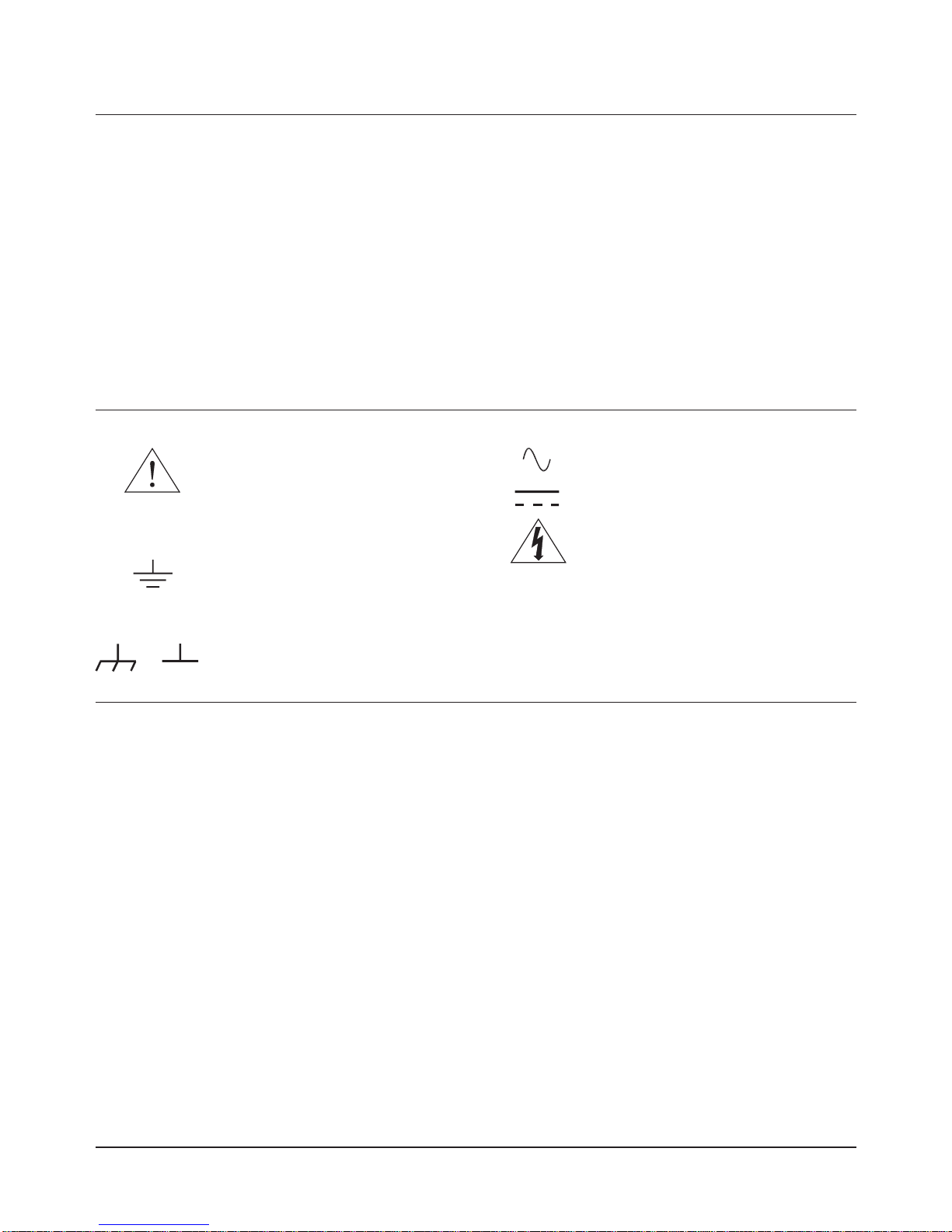
Safety Symbols
Instruction manual s ymbol affi xed to
product. Indicates that the user must refer to
the manual for specific WARNING or
CAUTION information to avoid personal
injury or damage to the product.
Alternating current (AC)
Instruction manual s ymbol affi xed to
product. Indicates that the user must refer to
the manual for specific WARNING or
CAUTION information to avoid personal
injury or damage to the product.
Indicates the field wiring terminal that must
be connected to earth ground before
operating the equipment — protects against
electrical shock in case of fault.
Direct current (DC).
Indicates hazardous voltages.
or
Frame or chassis ground terminal—typically
connects to the equipment's metal frame.
WARNING
Calls attention to a procedure, practice, or
condition that could cause bodily injury or
death.
CAUTION
Calls attention to a procedure, practice, or
condition that could possibl y cause damage to
equipment or permanent loss of data.
WARNINGS
The following general safety precautions must be observed during all phases of operation, service, and repair of this product. Failure to
comply with these precautions or with specific warnings elsewhere in this manual violates safety standards of design, manufacture, and
intended use of the product. Hewlett-Pa ckard Company assumes no liability for th e customer's failure to comply with these require ments.
Ground the equipment: For Safety Class 1 equipment (equipment having a protective earth terminal), an uninterruptible safety earth
ground must be provided from the mains power source to the product input wiring terminals or supplied power cable.
DO NOT operate the product in an explosive atmosphere or in the presence of flammable gases or fumes.
For continued protection against fir e, replace th e lin e fuse(s) on l y with fuse(s) of the same volt age and curren t rating and type. DO NOT
use repaired fuses or short-circuited fuse holders.
Keep away from live circuits: Operating personnel must not remove equipment covers or shields. Procedu res in volving th e removal of
covers or shields are for use by service-trained personnel only. Under certain conditions, dangerous voltages may exist even with the
equipment switched off. To avoid dangerous electrical shock, DO NOT perform procedures involving cover or shield removal unless you
are qualified to do so.
DO NOT operate damaged equipment: Whenever it is possible that the safety protection features built into this product have been
impaired, either through physical damage, excessive moisture, or any other reason, REMOVE POWER and do not use the product until
safe operation can be verified by service-trained personnel. If necessary, return the product to a Hewlett-Packard Sales and Service Office
for service and repair to ensure that safety features are maintained.
DO NOT service or adjust alone: Do not attempt internal service or adjustment unless another person, capable of rendering first aid and
resuscitation, is present.
DO NOT substitute parts or modify equipment: Because of the danger of introd ucing ad ditional h azards, do not install subst itute parts
or perform any unauthorized modification to the product. Return the product to a Hewlett-Packard Sales and Service Office for service
and repair to ensure that safety features are maintained.
Documentation History
All Editions and Updates of this manual and their creation date are listed below. The first Edi tion of the manu al is Editi on 1. The Edition
number increments by 1 whenever the manual is revised. Updates, which are issued between Editions, contain replacement pages to
correct or add additional information to the current Edition of the manual. Whenever a new Edition is created, it will contain all of the
Update information for the p revious Edition . Each new Editi on or Update also includ es a revised copy of th is documentation histor y page.
Edition 1 . . . . . . . . . . . . . . . . . . . . . . . . . . . . . . . . . . . . . . . . . . September, 1997
Page 5

5
Jim White, QA Manager
European contact: Your local Hewlett-Packard Sales and Service Office or Hewlett-Packard GmbH, Department HQ-TRE, Herrenberger Straße 130, D-71034 Böblingen, Germany (FAX +49-7031-14-3143)
Declaration of Conformity
according to ISO/IEC Guide 22 and EN 45014
Manufacturer's Name: Hewlett-Packard Company
Loveland Manufacturing Center
declares that the product:
Product Name: HP E8400A C-Size VXI Mainframe
Model Number: HP E8400A
Product Options: All
conforms to the following Product Specifications:
Safety: IEC 61010-1 (1990) including Amendments 1 (1992) and 2 (1995)
EN 61010-1 (1993) including Amendment 2 (1995)
CSA C22.2 #1010.1 (1992)
UL 3111-1 (1994)
EMC: CISPR 11:1990/EN55011 (1991): Group 1 Class A
EN61000-3-2:1995 Class A
EN61000-3-3:1995
EN50082-1:1992
IEC 801-2:1991: 4kV CD, 8kVAD
IEC 801-3:1984: 3 V/m
IEC 801-4:1988: 1kV Power Line, 0.5kV Signal Lines
ENV50141:1993/prEN50082-1 (1995): 3 Vrms
ENV50142:1994/prEN50082-1 (1995): 1 kV CM, 0.5 kV DM
EN61000-4-8: 1993/prEN50082-1 (1995): 3 A/m
EN61000-4-11:1994/prEN50082-1 (1995): 30 %, 10 ms 60 %, 100ms
Supplementary Information: The product herewith complies with the requirements of the Low Voltage Directive
73/23/EEC and the EMC Directive 89/336/EEC (inclusive 93/68/EEC) and carries the "CE" mark accordingly.
September, 1997
Page 6

6
Notes:
Page 7
NO POSTAGE
NECESSARY
IF MAILED
IN THE
UNITED STATES
fold here
Please fold and tape for mailing
Reader Comment Sheet
HP E8400A C-Size VXI Mainframe User/Service Manual
Edition 1
You can help us improve our manuals by sharing your comments and suggestions. In appreciation of your time, we will
enter you in a quarterly drawing for a Hewlett-Packard Palmtop Personal Computer (U.S. government employees
are not eligible for the drawing).
Your Name
Company Name
Job Title
Address
City, State/Province
Country
Zip/Postal Code
Telephone Number with Area Code
Please list the system controller, operating system, programming language, and plug-in modules you are using.
BUSINESS REPLY MAIL
FIRST CLASS PERMIT NO. 37 LOVELAND, CO
POSTAGE WILL BE PAID BY ADDRESSEE
HEWLETT-PACKARD COMPANY
Measurement Systems Division
Learning Products Department
P.O. Box 301
Loveland, CO 80539-9984
fold here
Please pencil-in one circle for each statement below: Disagree Agree
• The documentation is well organized. OOOOO
•
Instructions are easy to understand. OOOOO
•
The documentation is clearly written. OOOOO
•Examples are clear and useful. OOOOO
•
Illustrations are clear and helpful. OOOOO
•
The documentation meets my overall expectations. OOOOO
Please write any comments or suggestions below–be specific.
cut along this li ne
Page 8

Page 9
Using the HP E8400A Mainframe 9Chapter 1
Chapter 1
Using the HP E8400A Mainframe
Chapter Overview
This chapter contains information on the operating features of the
HP E8400 VXI mainframe. The sections of this chapter include:
• Product Ov erview . . . . . . . . . . . . . . . . . . . . . . . . . . . . . . . . . 9
• Front Panel Features . . . . . . . . . . . . . . . . . . . . . . . . . . . . . . . 10
• Preparing Your VXI System for Use. . . . . . . . . . . . . . . . . . . 13
Product Overview
The HP E8400A VXI mainframe is designed in full compliance with
VXIbus specification revision 1.4, VXIplug&play specification VPP-8, and
VMEbus system specification revision C.1. Additional features of the HP
E8400A mainframe include:
•Mainframe monitoring for instant verification of:
n
backplane voltage conditions
n
mainframe temperatures
n
fan and impeller operation
n
data flow
•State of the art cooling technology:
n
quiet, variable speed power supply fan and backp lane impeller
n
increased static pressure
•Front panel Diagnostic connector for:
n
power supply voltage measurements
n
power supply and backplane temperature measurements
n
power supply fan and backplane impeller v er ification
n
+5V and +12V voltage source
•Easy maintenance:
n
rear panel access to power supply, power supply fan, and cooling
impeller for either bench or rack mount operation
Page 10

10 Using the HP E8400A Mainframe Chapter 1
Front Panel Features
The HP E8400A front panel allows you to monitor power supply voltages,
mainframe temperatures, fan operation, and communication across the
backplane. Table 1-1 describes these features.
Table 1-1. HP E8400A Mainframe Front Panel Indicators and Switches.
Section Indicator / Switch Description
Input Power On Indicator Green - the mainframe is turned on.
Off - there is no power applied to the mainfram e. The mai nframe is turned of f
but may be plugged into an AC power source.
Power Supply Volta ges Indicator
Temp Indicator
Green - all voltages on the VXI backplane are within ±8% of the VXI
specification.
Flashing Amber - one or more voltage s is out of spe cificati on. Th e backpl ane
voltages and allowed variations are listed below:
Voltage Allowed Variation Diagnostic Pin
+5V +4.875V to +5.125V 1
+12V +11.64V to +12.6V 14
-12V -12.6V to -11.64V 2
+24V +23.28V to +25.2V 15
-24V -25.2V to -23.28V 3
-5.2V -5.46V to -5.044V 16
-2V -2.1V to -1.9V 4
Green - the power supply temperature is acceptable.
Flashing Amber - the power supply is approaching thermal shutdown. The
power supply temperature can be measured on pin 11 of the Diagnostic
connector.
Fans Fan Switch
Fans Indicator
Full - the power supply and mainframe cooling fans are operating at full
speed.
Var(iable) - the power supply and mainframe cooling fans are providing
adequate cooling (default setting). Fan speed is a functi on of the power
supply tempera ture and the referen ce temper ature (Dia gnosti c con nec tor pin
12). The reference temperature is a function of ambient temperature and
load.
Green - the power supply and mainframe cooling fans are operating.
Flashing Amber - the power supply fan or the mainframe cooling fan is not
operating. Fan operation can be checked using pin 13 of the Diagnostic
connector.
Backplane Activity Indicator
SYSFAIL Indicator
Reset Switch
Green - there is communication between instruments across the backplane.
Off - there is no communication between instrume nts on the backpla ne.
Flashing Ambe r - one or mo re instru ments has ass erted it s SYSF AI L line du e
to a power-on initialization failure, self-test failure, or hardware failure.
SYSFAIL is asserted momentarily at power on and during a system reset.
Resets all installed instruments to their power-on states.
Page 11

Using the HP E8400A Mainframe 11Chapter 1
Diagnostic
Connector
The 25-pin Sub-D diagnostic connector provides access to backplane
voltages, power supply an d backplane temperature s, and output signals. The
pins are described in Table 1-2.
Table 1-2. Diagnostic Connector Pin Descriptions
Pin # Function Description
1 +5 VM +5V backplane voltage monitor (high impedance).
2 -12 VM -12V backplane voltage monitor (high impedance).
3 -24 VM -24V backplane voltage monitor (high impedance).
4 -2 VM -2V backplane voltage monitor ( high impedance).
5 Rem Stdby Remote power on. See "Using the Remote Power-on Pins."
6 +5 VC +5 VDC source output (1A maximum).
7 +12 VC +12 VDC source output (1A maximum).
8 +5 V Stdby Input for +5V STDBY (1A maximum for pins 8 and 21 combined).
9 GND Chassis ground.
10 SysReset * TTL low-true input signal causes system reset, output indicates system reset.
1 1 PS Temp
Output voltage proporti onal to power supply temperature
( 0 VDC at 0° C, with a
rise of 10 mV per degree centigrade).
12 Ref Temp
Output voltage proportional to backplane temperature
( 0 VDC at 0° C, with a
rise of 10 mV per degree centi grade). A func tio n of the ambi ent tempe ratu re and
load. At no load, T
ref
~ 2 °C + ambient. At full load and high fan speed,
T
ref
~ 14 °C + ambient. At full load and low fan speed, T
ref
~ 20 °C + ambient.
13 Fans OK * TTL low-true output voltage indicates power supply and backplane cooling fans
are operating.
14 +12 VM +12V backplane voltage monitor ( high impedance).
15 +24 VM +24V backplane voltage monitor (high impedance ).
16 -5.2 VM -5.2V backplane voltage monitor ( high impedance).
17 GND Chassis ground.
18 REM SW Remote power switch return. See "Using the Remote Power-On Pins.".
19 V OK * TTL low-true output voltage indicating the +5V, ± 12V, ± 24V, -5.2V, and -2V
power supply voltages ar e within ± 8% of its al l owed variation.
20 GND Chassis ground.
21 +5 V Stdby Input for +5V STDBY (1A maximum for pins 8 and 21 combined).
22 GND Chassis ground.
23 ACFAIL * TTL low-true output asserted by the mainframe power monitor at po wer d own or
whenever a loss of power is detected.
24 GND Chassis ground.
25 N/C Unu sed.
Page 12
12 Using the HP E8400A Mainframe Chapter 1
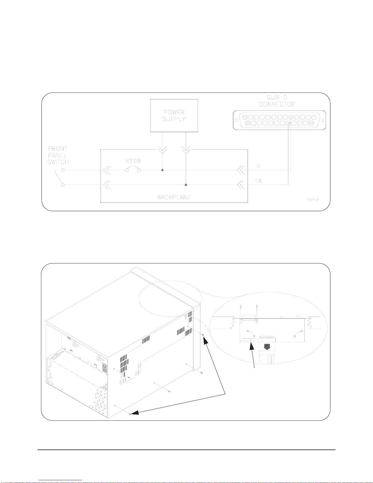
Using the Remote
Power-On Pins
The remote power-on pins (pins 5 and 18) allow you to turn the mainframe
on and off without using the front panel On/Stdby switch. With the
On/Stdby switch in the Stdby (off) position, connecting pin 5 to pin 18 on
the diagnostic connector turns the mainframe on. Disconnecting pin 5 from
pin 18 turns the mainframe off.
Disabling the On/Stdby
Switch
The front panel On/Stdby switch is disabled by removing surface mount
resistor R108 located on the basic monitor board (Figure 1-2).
Figure 1-1. Remote Standby Switch Wiring.
Figure 1-2. Disabling the On/Stdby Switch by Removing R108
m3x6 flat head torx screws
(five per side)
location of R108
Page 13

Using the HP E8400A Mainframe 13Chapter 1
Caution After removing R108, heat damage may prevent the resistor
from being re-installed to re-enable the On/Stdby s witch.
To access the basic monitor board and resistor:
1. Turn off the mainframe and remove the power cord.
2. Remove the mainframe cover by removing the 10 m3x6 flat head torx
screws.
3. Remove the resistor by heating both sides simultaneously with
soldering irons. Separate the resistor from the board by gently
pressing the tips of the soldering irons together.
4. Save the resistor in order to re-enable the On/Stdby switch. Again,
heat damage may prevent the resistor from being re-installed.
Preparing Your VXI System for Use
The HP E8400A is shipped from the factory ready to use. However, before
installing VXI instruments and turning on the mainframe, refer to the
following:
•AC Power Requirements
•Airflow Requirements
•Installing VXI Instruments
AC Power
Requirements
The HP E8400A mainframe can be operated at line voltages of
90 VAC to 264 VAC, and line frequencies of 47 Hz to 66 Hz. The
mainframe can also operate at 360 Hz to 440 Hz with line voltages of
90 VAC to 132 VAC.
The mainframe ships with a power cord and with a 250V, 15A fast blow fuse
installed. The fuse is suitable for all line voltages. Refer to Chapter 3 for
additional information on E8400A power cords and on fuse replacment.
Appendix A contains complete input power specifications.
WARNING The p o wer cord is the only way to disconnect the mainframe
from AC power and, therefore, it must be accessible to the
operator at all times. When the HP E8400A is mounted in a
system cabinet, the power cord need not be accessible since
the cabinet must have its own disconnect device.
Page 14
14 Using the HP E8400A Mainframe Chapter 1
Connecting the
HP E8400A to a
Permanent Earth Ground
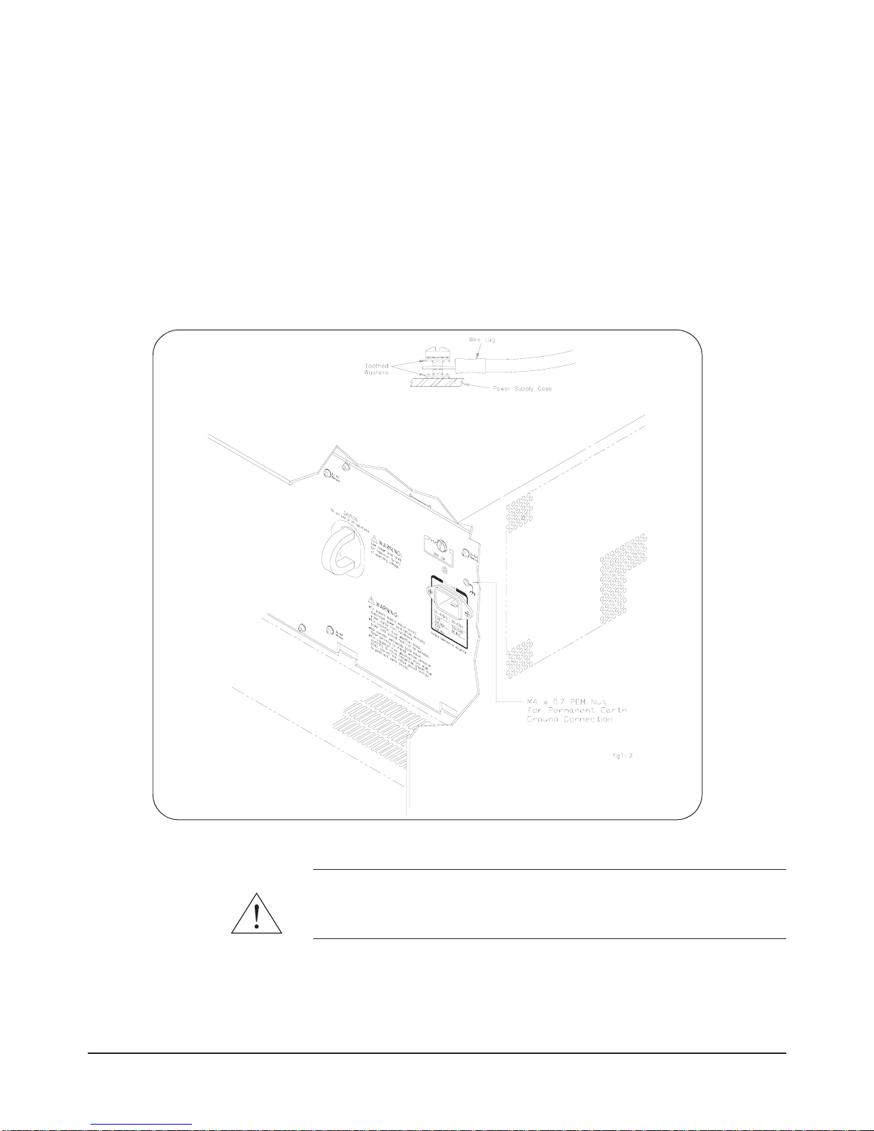
The mainframe must be connected to a permanent earth ground for line
frequencies greater than 66 Hz. This connection is made on the back of the
mainframe:
1. Connect a 16 AWG (1.3 mm or larger) wire to the PEM nut shown in
Figure 1-3. The wire mu st be green with a yellow stripe, or bare (no
insulation). Use a m4 x 10 screw , gr ounding lug, and toothed wa shers
(or toothed lug) as shown in the Figure.
2. Attach the other end of the wire to a permanent earth ground using
toothed washers or a toothed lug.
WARNING For prote ction from electrical shock when operating at
frequencies greater than 66 Hz, connect the chassis ground
terminal to permanent earth ground.
Figure 1-3. Connecting the HP E8400A to a Permanent Earth Ground
Page 15

Using the HP E8400A Mainframe 15Chapter 1
AVERTISSEMENT Risque de Choch èlectrique. Si la frèquence du secteur est
supèrieure à 66 Hz, relier la borne de masse du chassis à une
prise de terre fixe.
Positioning the
Mainframe for
Adequate Cooling
VXI instruments are cooled by air drawn through the back of the mainframe
and exhausted out the sides. The power supply is cooled by air drawn from
the right side (facing the mainframe) and exhaused out the left side. When
placing the mainframe on a work bench or if the mainframe is rack mounted,
provide at least a one inch clearance at the back and sides to allow for proper
air flow.
Installing VXI
Instruments
The HP E8400A mainframe has 13 slots labeled 0 through 12. Any VXI
instrument can be installed in any slot; however, slot 0 is reserved for
devices capable of providing the system’s slot 0 functionality. This
functionality includes:
•locating instruments installed in the mainframe
•managing (arbitrating) data flow across the backplane
•providing the system clock (SYSCLK - 16 MHz)
Examples of these devices are the HP E1406 Command Module and
embedded controllers such as the HP E6232/E6233 VXI Pentium PCs, the
HP RADEPC7B PC, and the HP E1497/E1498 V743 controllers.
Multiple instruments which combine to create a virtual instrument (e.g. a
scanning multimeter), and instruments which access the backplane local bus
should be installed in adjacent slots.
Note Hewlett-Packard VXI Installation Consultant (HP VIC) is an
excellent tool for installing and configuring VXI systems. The
program guides you through hardware installation, driver
installation, and system self-test. HP VIC is available on the World
Wide Web starting at http://www.hp.com/go/inst_drivers.
Installing C-Size
Instruments
Figure 1-4 shows the installation of C-Size instruments.
Page 16
16 Using the HP E8400A Mainframe Chapter 1
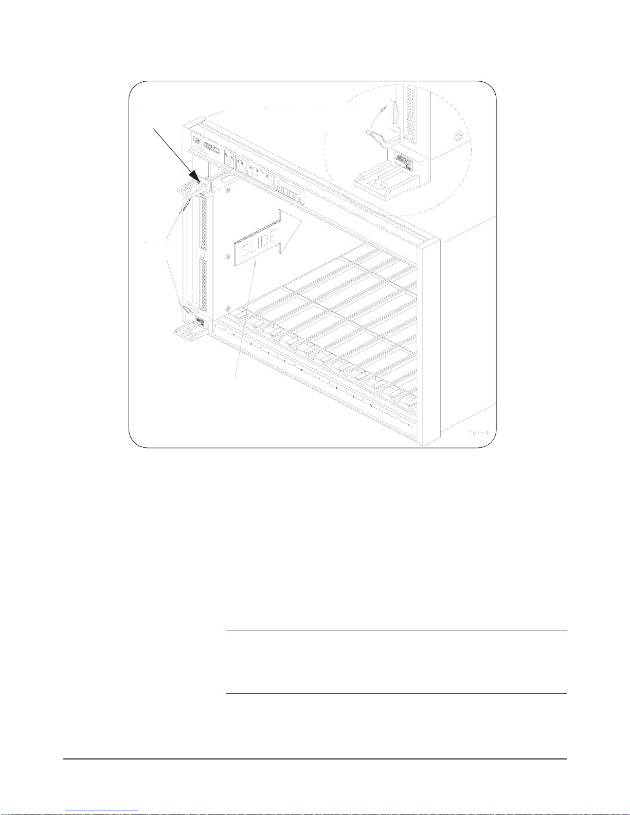
1. To prevent damage to the VXI instruments, install the instruments
when power is not applied to the mainframe.
2. Insert the instrument into the mainframe by aligning the instrument
with the card guides inside the mainframe. Slowly push the
instrument into the slot until it seats in the backplane connectors. The
front panel of the instrument should be even with the front edges of
the mainframe.
3. Tighten the retaining screws on the top and bottom of the module.
WARNING All instruments within the VXI mainframe are grounded through
the mainframe chassis. During installation, tighten the
instrument's retaining screws to secure the instrument to the
mainframe and to make the ground connection.
Figure 1-4. Installing C-Size Instruments in the HP E8400A Mainframe
seat the module by
pushing in the
extraction levers
slide the module
into the mainframe
until it plugs into the
backplane connectors
extraction
levers
retaining
screws
Page 17

Using the HP E8400A Mainframe 17Chapter 1
Installing A- and B-Size
Instruments
A-, B-, and C-size instruments can be installed in the mainframe. A- and
B-size instruments are installed using a module carrier:
•HP E1403B A/B-size Module Carrier extends the P1 connector on
the VXIbus backplane and mounts the (A/B-size) modules flush with
C-size modules. This carrier is recommen ded for Hewlett-Packard
B-size, slave-only devices which have the P1 connector.
•HP E1407A A/B Module Carrier extends the P1and P2 connectors
on the VXIbu s backplane. This carrier is r eco mmended for B-Size,
slave-only devices which have the P1/P2 connectors.
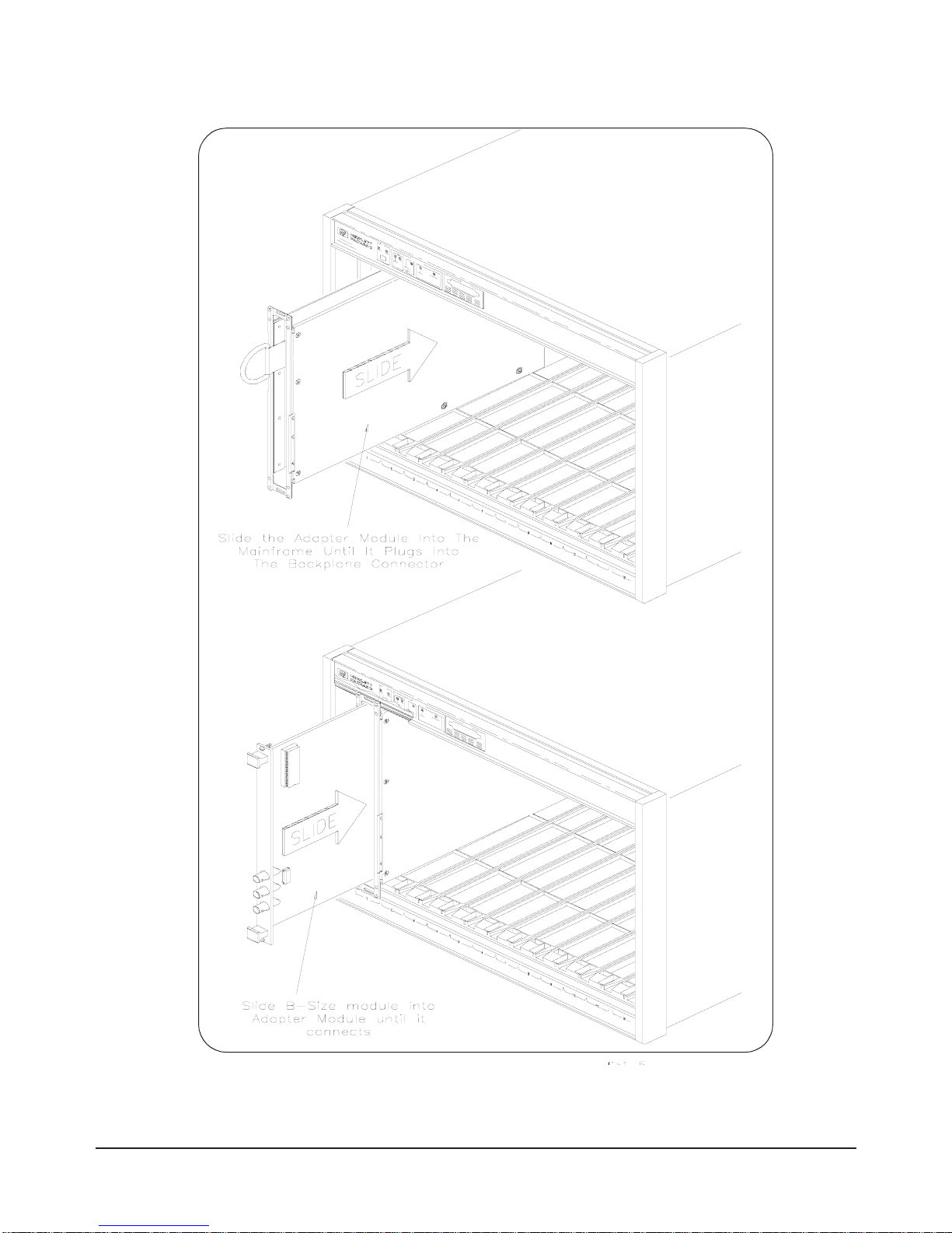
Figure 1-5 shows the installation of A- and B-size instruments.
Page 18
18 Using the HP E8400A Mainframe Chapter 1
Figure 1-5. Installing A- and B-Size Instruments in the HP E8400A Mainframe
Page 19

Using the HP E8400A Mainframe 19Chapter 1
1. To prevent damage to the VXI instruments, install the instruments
when power is not applied to the mainframe.
2. Install the HP E1403 A/B-size Module Carrier or the HP E1407
A/B-size Module Carrier into the mainframe. This is done by
aligning the top and bottom of the carrier with the card guides and
slowly pushing the carrier into the mainframe. The front of the
carrier should be even wi th the front edges of the mainframe.
3. Slide the A- or B-Size instrument into the carrier until it connects.
4. Tighten the retaining screws on the top and bottom of the instrument.
WARNING All instruments within the VXI mainframe are grounded through
the mainframe chassis. During installation, tighten the
instrument's retaining screws to secure the instrument to the
mainframe and to make the ground connection.
Page 20

20 Using the HP E8400A Mainframe Chapter 1
Page 21

Rack Mounting and Option Installation 21Chapter 2
Chapter 2
Rack Mounting and Option Installation
Chapter Overview
This chapter contains procedures for rack mounting the mainframe and for
installing the hardware options available with the mainframe.The sections in
this chapter include:
• Rack Mounting the HP E8400A Mainframe. . . . . . . . . . . . . 21
• Installing the Cable Tray. . . . . . . . . . . . . . . . . . . . . . . . . . . . 32
• Installing the Tinted Acrylic Door . . . . . . . . . . . . . . . . . . .34
• Installing the Intermodule Chassis Shields . . . . . . . . . . . . .36
• Installing the Backplane Connector Shields. . . . . . . . . . . . .38
• HP E8400A Air Filter Kit . . . . . . . . . . . . . . . . . . . . . . . . .39
Rack Mounting the HP E8400A Mainframe
The HP E8400A is mounted into standard EIA cabinets using the rack mount
adapter kits and support rail or rack slide kit shown in Table 2-1.
When rack mounting the mainframe, you must order an adapter kit and the
rail or rack slide kit supported by the adapter.
Parts List The parts included with each rack mount adapter kit and the support rail and
slide rail kits are shown in Table 2-2.
Table 2-1. HP E8400A Rack Mount Kits.
Rack Mount Adapter Kits Rail and Rack Slide Kits
HP E8400A Standard Adapter Kit
HP p/n E8400-80923
Support Rail Kit HP E3664A
or
Rack Slide Kit HP p/n 1494-0411
HP E8400A Flush Mount Adapter Kit
HP p/n E8400-80924
Support Rail Kit HP E3664A
HP E8400A VXIplug&play Compliant
Adapter Kit
HP p/n E8400-80925
Support Rail Kit HP E3663A*
or
Rack Slide Kit HP p/n 1494-0411
* This adapter kit can also be used with the HP E3665A rail kit.
Page 22

22 Rack Mounting and Option Installation Chapter 2
Table 2-2. Rack Mount Adapter, Support Rail, and Rack Slide Parts Lists.
Quantity Description Part Number
HP E8400A Standard Adapter Kit (HP p/n E8400-80923)
1 Rack Mount Adapter (left) E8400-61203
1 Rack Mount Adapter (right) E8400-61204
2 Handles *
4 Handl e S crew s - m5x10 flat head 0515-1020
8 Adapt er-to-Mainframe Screws - m5x8 pan head 0515-0979
4 Adapter Dress Sc rews 0570-1577
4 Channel Nuts (for adapter dress screws) 0590-0804
HP E8400A Flush Mount Adapter Kit (HP p/n E8400-80924)
1 Rack Mount Adapter (left) E8400-61205
1 Rack Mount Adapter (right) E8400-61206
4 Adapt er-to-Mainframe Screws - m5x8 pan head 0515-0979
4 Adapter Dress Sc rews 0570-1577
4 Channel Nuts (for adapter dress screws) 0590-0804
HP E8400A VXIplug&play Compliant Adapter Kit (HP p/n E8400-80925)
1 Rack Mount Adapter (left) E8400-61207
1 Rack Mount Adapter (right) E8400-61208
4 Fixture Screws - m5x12 flat head 0515-0956
8 Adapt er-to-Mainframe Screws - m5x8 pan head 0515-0979
6 Adapter Dress Sc rews 0570-1577
6 Channel Nuts (for adapter dress screws) 0590-0804
Support Rails (HP E3664A)
2 Support Rails E3664-00001
4 Channe l Nuts (for support rail-to-rack) 0590-0804
4 Support Rail-to-Rack Screws - 0.5x10.32 2680-0278
Rack Slides (HP p/n 1494-0411)
2 Rack Slides **
8 Rack Slide-to-Adapter Screws - m5x8 flat head 0515-1019
8 Channel Nuts (for slide rails) 0590-0804
4 Rack Slide-to-Rack Front Screws - m5x12 flat head 0515-0956
Page 23

Rack Mounting and Option Installation 23Chapter 2
Rack Mounting the
HP E8400A using
Support Rails
This section contains instructions for mounting the HP E8400A mainframe
in an EIA cabinet using th e HP E3664A support rail kit. The E36 64A kit can
be used with any of the rack mount adapter kits; however, the E3664A is
only compatible with HP cabinets. The following procedures apply to all
adapters, with adapter-specific information noted where necessary.
Note If you ordered Cable Tray Option 914, refer to page 32 and install the tray
before rack mounting the mainframe.
Procedure 1. Attach the handles to the adapters using the m5x10 flat head screws
(Figure 2-1). Handles are included only with the HP E8400A
Standard Adapter Kit (p/n E8400-80923).
4 Rack Slide-to-Rack Rear Screws - m5x12 pan head 0515-0904
* AMATOM p/n 10939-A-032-2
** General Devices p/n CC1502-99-0016
Table 2-2. Rack Mount Adapter, Support Rail, and Rack Slide Parts Lists.
Quantity Description Part Number
Figure 2-1. Attaching Handles to the Adapters (Standard kit p/n E8400-80923).
m5x10 flat head screws
Page 24

24 Rack Mounting and Option Installation Chapter 2
2. Using the rack mount adapters as templates, position the adapters on
the rack’s vertical rails where the mainframe is to be mounted. Align
the adapter holes over the "center" holes of the EIA rack units (Figure
2-2).
Note If you are using the HP E8400A VXIplug&play Compliant adapter kit,
position the adapters such that all three mounting holes are directly over
holes on the rack’s vertical rails, and that the adapter flanges cover nine full
EIA rack units with no overlap.
3. Slide channel nuts over the rack holes to be used by the rack mount
adapters.
Figure 2-2. Positioning the Mainframe in the Rack.
EIA rack unit
center holes
EIA rack unit
center holes
rack mount
adapters
one
rack
unit
rack unit
center hole
Page 25

Rack Mounting and Option Installation 25Chapter 2
4. Attach the support rails to the rack’s inside vertical rails. The support
rails must be positioned behind the bottom channel nuts installed in
Step 3 (Figure 2-3). Use four channel nuts and the four 0.5x10⁻³²
support rail-to-rack pan head screws to secure the rail.
Figure 2-3. Attaching the Support Rails to the Rack.
0.5x10.32 pan head screws
position rail behind
bottom channel
nut
Page 26

26 Rack Mounting and Option Installation Chapter 2
5. Attach the rack mount adapters to the mainframe using the m5x8 pan
head screws provided. To mount the mainframe flush with the rack
front, begin with the 3rd hole from the front of the adapter (Figure
2-4).
With the standard adapter kit ( p/n E8400-80923), the mainframe can
be recess mounted up to 270.7 mm (10.6 inches), or extended out
from the rack up to 147.6 mm (5.8 inches) in 12.3 mm (approximately
1/2 inch) increments.
The rack mount adapters for the VXI compliant and flush mount kits
are also shown in Figure 2-4.
Figure 2-4. Attaching the Rack Mount Adapter to the Mainframe.
m5x8 pan head screws
recess mount in 12.3 mm
(~1/2 inch) increments
flush mount adapter
p/n E8400-80924
VXIplug&play complian t adapter
p/n E8400-80925
standard adapter
p/n E8400-80923
Page 27

Rack Mounting and Option Installation 27Chapter 2
6. Remove the mainframe feet by lifting the tabs and sliding the feet
towards the center of the mainframe.
7. With one person on each side of the mainframe, lift the mainframe
onto the support rails. Slide the mainframe into the rack until the rack
mount adapt er flanges are against the rack’s vertical rails. Secure the
mainframe to the rack using the adapter dress screws.
WARNING To prevent injury during rack mounting, the mainframe should
be empty and two people should lift the mainframe into the
rack.
Rack Mounting the
HP E8400A Using
Rack Slide Rails
This section contains instructions for mounting the HP E8400A mainframe
in an EIA cabinet
using the rack slide kit (p/n 1494-0411). The rac k slide kit,
which is used with either the Standard Adapter kit (p/n E8400-80923) or the
VXIplug&play Compliant kit (p/n E8400-80925), allows you to extend the
mainframe from the cabinet for easier access to installed instruments.
The following procedures apply to the adapter kits listed above, with
adapter-specific information noted where necessary. The rack slide kit is not
used with the flush mount adapter kit (p/n E8400-80924)
Procedure 1. Attach the handles t o the st andard adapters using th e m5x10 fl at head
screws (Figure 2-5). Handles are included only with the HP E8400A
Standard Adapter Kit.
Figure 2-5. Attaching Handles to the Adapters (Standard kit p/n E8400-80923).
m5x10 flat head screws
Page 28

28 Rack Mounting and Option Installation Chapter 2
2. Using the rack mount adapters as templates, position the adapters on
the rack’s vertical rails where the mainframe is to be positioned. Be
sure to align the adapter holes over center hole s on the vertical rail
(Figure 2-6).
If you are using the HP E8400A VXIplug&play Compliant adapter
kit, position the adapters such that all three mounting holes are
directly over holes on the rack’s vertical rails, and that the adapter
flanges cover nine full EIA rack units with no overlap.
3. Slide channel nuts over the rack center holes to be used by the rack
mount adapters.
Figure 2-6. Positioning the Mainframe in the Rack.
EIA rack unit
center holes
EIA rack unit
adapters
rack
rack unit
center hole
rack mount
center holes
one
unit
Page 29

Rack Mounting and Option Installation 29Chapter 2
4. From the bottom channel nut inserted in Step 3, count up four holes.
Slide a channel nut over the corresponding hole on the inside vertical
rail (Figure 2-7). Install a second channel nut on the inside rail four
holes above the first nut. Repeat for the other rail. Install channel nuts
on the corresponding holes on the rear inside rails.
Figure 2-7. Positioning the Rack Slides (using the Standard Adapter Kit).
channel nuts on
center holes
channel nuts on
center holes
channel nuts for
rack slides
left vertical rail right vertical rail
(front)
(front)
four holes
four holes
Page 30

30 Rack Mounting and Option Installation Chapter 2
5. Remove the chassis section from the intermediate section (Figure
2-8). (The chassis section will be connected to the mainframe in Step
7.) Slide the intermediate section back into the stationary section.
6. Attach the stationary section to the rack’s front inside rail through the
channel nuts. Use two m5x12 flat head screws. Attach the stationary
section to the rear inside rail using two m5x12 pan-head screws
(Figure 2-9).
7. Attach the rack mount adapters to the mainframe using the eight
m5x8 pan head screws provided. To mount the mainframe flush with
the rack front, begin with the 3rd hole from the front of the adapter
(Figure 2-10).
Figure 2-8. Removing the Rack Slide Chassis Section from the Intermediate Section.
chassis section
intermediate se ction
rack front
rack rear
stationary section
(right rack slide shown)
depress from back
side to remove
Figure 2-9. Installing the Rack Slide Stationary Sections.
rack front
rack rear
m5x12 flat head screws
m5x12 pan head screws
(left rack slide shown)
(standard adapter kit)
(standard adapter kit)
mounting holes when using
the VXIplug&play Compliant adapters
Page 31

Rack Mounting and Option Installation 31Chapter 2
The mainframe can be recess mounted up to 270.7 mm (10.6 inches)
in approximately 12.3 mm (1/2 inch) increments. Note that in some
recess positions, the front screw attaching the rack slide adapter may
have to be removed.
8. Attach the chassis sections to t he rack mount adapters us ing four
m5x8 flat head screws per side (Figure 2-10).
9. If additional rack space is required for other instruments, remove the
mainframe feet by lifting the tabs and sliding the feet towards the
center of th e mainframe.
10.Slide the rack slide intermediate sections out from the rack slide
stationary sections until they lock into place. With one person on each
side, lift the mainframe and slide the chassis sections into the
intermediate sections until the chassis sections lock into place. Slide
the mainframe into the rack until the rack mount adapter flanges are
against the rack’s vertical rails. Secure the mainframe to the rack
using the adapter dress screws.
Figure 2-10. Attaching the Rack Mount Adapters and Chassis Sections to the Mainframe.
m5x8 pan head screws
m5x8 flat head screws
chassis sections
Standard rack mount
adapter (p/n E8400-80923)
VXIplug&play Compliant rack
mount adapter (p/n E8400-80925)
Page 32

32 Rack Mounting and Option Installation Chapter 2
WARNING To prevent injury during rack mounting, the mainframe should
be empty and two people should lift the mainframe into the
rack.
Installing the Cable Tray
The HP E8400A Cable Tray (Option 914) allows you to route VXI
instrument cables and wires under the mainframe. The cable tray can be used
when the mainframe is on a bench top or when mounted in a standard EIA
cabinet. The tray is compatible with the support rail (HP E3664A) and rack
slide (HP p/n 1494-0411) kits.
Note If you ordered the support rail (HP E3664A) or rack slide (p/n 1494-0411)
kit, install the cable tray before rack mounting the mainframe.
Parts List The parts included in Option 914 are shown in Table 2-3.
Procedure 1. Remove the four mainframe feet by lifting the tabs and moving each
foot towards the center of the mainframe.
2. Attach the cable tray to the mainframe as shown in Figure 2-11 using
four m5x8 pan head scre ws. Select the tray holes based on th e amount
of cable clearance required.
The bottom mounting holes position the tray over one additional EIA
rack unit (44.5 mm), the top holes position the tray over two EIA rack
units, and the center holes position the tray between one and two EIA
rack units.
Note If the mainframe is mounted extending out from the rack, install the cable
tray with the notched end at the front of the mainframe.
3. If the mainframe will be placed on a bench top, attach the mainframe
feet to the cable tray. If the mainframe is to be rack mounted, you can
save rack space by leaving the feet off.
Table 2-3. HP E8400A Cable Tray Option 914 Parts List.
Quantity Description Part Number
1 Cable Tray E8400-04102
4 Cable Tray-to-Mainframe Screws - m5x8 pan head 0515-0979
Page 33

Rack Mounting and Option Installation 33Chapter 2
Note Holes are provided at each end of the cable tray for mounting a
customer-supplied interface panel. The maximum height of the panel must
be 41.275 mm for a one EIA rack unit cable tr ay position, or 85.725 mm for
a two EIA rack unit cable tray position.The panel width cannot exceed 424
mm. The four holes across the bottom are 101.6 mm center-to-center, and
centered on the tray. The side holes are 34.9 mm center-to-center, with the
bottom hole 25.4 mm above the tray’s inside surface. All holes are 12.7 mm
from the edge and have a diameter of 3.175 mm.
Figure 2-11. Installing the Cable Tray.
m5x8 pan head screws
select holes based
on cable clearance
required
holes for mounti ng
customer-supplied
interface panel
Page 34

34 Rack Mounting and Option Installation Chapter 2
Installing the Tinted Acrylic Door (Option 915)
This procedure describes how to install the Tinted Acrylic Door on the HP
E8400A mainframe. The door requires the Standard Adapter Kit (p/n
E8400-80923), and is compatible with either the support rail kit (HP
E3664A) or the rack slide kit (p/n 1494-0411).
Parts List The parts included in Option 915 are shown in Table 2-4.
Note The door requires the mainframe to be recess mounted a minimum of
111 mm (4.36") or up to a maximum of 270.7 mm (10.6 inches) to
accommodate wiring terminals on the VXI instruments. When using the
minimum recess distance, field wiring cables must enter/exit the
instruments through the top and/or bottom openings only.
Procedure 1. Recess mount the mainframe a minimum of 111 mm
(4.36 inches) using the Standard Adapter kit and either the support
rail kit (
page 23) or rack slide kit (page 27).
Note For the minimum recess distance, attach the rack mount adapters to the
mainframe beginning with the 12th hole from the front of the adapter.
2. If necessary, remove the dress screws (0570-1577) securing the
adapters to the rack.
3. Attach the hinge pins to the right rack mount adapter using four
m5x10 flat head screws (Figure 2-12). Attach the rubber door stops
and door latch to the left ad apt er using four m3x8 p an h ead s cr ews a s
also shown in Figure 2-12.
Table 2-4. HP E8400A Option 915 Parts List.
Quantity Description Part Number
1 Acrylic Door Assembly E8400-09301
2 Hinges 3110-0409
1 Door Latch, Lock, and Keys 1390-0891
2 Rubber Door Stops 0403-0002
4 Screws - m5x10 flat head 0515-1020
4 Screws - m3x8 pan head 0515-0897
Page 35

Rack Mounting and Option Installation 35Chapter 2
4. Slide the mainframe into the rack until the rack mount adapters
contact the rack’s vertical rails.Start the dress screws but do not
tighten.
5. Install th e door asse mbly b y placing the hing es over the hin ge pins on
the right adapter. Adjust the door for squareness and clearance by
holding the door in place while tightening the dress screws.
6. Adjust the latch keeper so that the door latches as it makes contact
with the rubber door stops.
Figure 2-12. Installing the Acrylic Door Hinges, Door Stops, and Latch Keeper.
m5x10 flat head screws
hinge pins
rubber door stop
m3x8 pan head screws
door latch
Page 36

36 Rack Mounting and Option Installation Chapter 2
Note Once installed and adjusted, the door can be removed when necessary by
lifting the door off the hinge pins.
Installing the Intermodule Chassis Shields
This procedure describes how to install chassis shields in the
HP E8400A mainframe. The chassis shield is HP’s implementation of VXI
revision 1.4, specification B.7.3.4 that allows grounded shielding between
mainframe slots. The shield is used to isolate VXI modules that generate
electromagnetic interference (EMI) at excessive levels, or to protect VXI
measurement modules from noise sources.
WARNING Do not install intermodule chassis shields while the mainframe
is turned on or plugged into an AC power source.
Parts List The parts included in the HP E8400-80909 Chassis Shield Kit are shown in
Table 2-5.
Procedure
Note Each mainframe slot has top and bottom chassis shield guides (Figure
2-13). Chassis shields should be installed on both sides of an instrument
generating interference/noise, or installed on both sides of a sensitive
instrument.
1. Insert grounding springs into the four sockets (two top, two bottom)
along the shield guides (Figure 2-13). Use a small flat blade
screwdri ver to secure each spring under the socket t ab.
Use the chassis shield to cover the vent holes inside the mainframe
when installing grounding springs in the top guide sockets. This
prevents the springs from falling into the mainframe if they are
accidently dropped.
T able 2-5. HP E8400-80909 Parts List.
Quantity Description Part Number
1 Chassis Shield E8400-00600
8* Grounding Spring E8400-09101
* Includes 4 extra springs.
Page 37

Rack Mounting and Option Installation 37Chapter 2
2. Align the chassis shield with the shield guides and gently slide the
shield into the mainframe. Be careful not to crimp the front grounding
springs with the edge of the shield. Slide the shield in until it reaches
the end of the shield guide.
Figure 2-13. Installing the Grounding Springs and Chassis Shield.
VXI module guide
grounding spring socket
chassis shield guide
use a small screw driver
to secure spring under
socket tab
Page 38

38 Rack Mounting and Option Installation Chapter 2
Installing the Backplane Connector Shields
This procedure describes how to install backplane connector shields in the
HP E8400A mainframe. The shields are HP’s implementation of VXI
revision 1.4, specification B.7.2.3 which ensures compliance with RFI
levels specified in standards EN55011 and CISPR11.
Note A number of VXI instruments require shields for compliance with
EN55011 and CISPR11. Refer to the instrument documentation to
determine if shields are required.
WARNING Do not install backplane connector shields while the mainframe
is turned on or plugged into an AC power source.
Parts List The parts included in Option 918 are shown in Table 2-6.
Procedure 1. Position the shields over the backplane connectors as shown in Figure
2-14. Two connector shields and four screws are required for each
slot.
Table 2-6. HP E8400A Option 918 Parts List.
Quantity Description Part Number
54* Torx Head Screw - 4-20x.25 0624-0702
1 Torx Driver 8710-1989
26 Backplane Connector Shield E1400-80601
* Includes two extra screws
Page 39

Rack Mounting and Option Installation 39Chapter 2
2. T o install the Torx screws, firmly press the screw onto the Torx driver.
This prevents the screw from falling off as you reach into the
mainframe. Placing a sheet of paper under the backplane connectors
will catch screws if they fall.
3. Tighten the screws by turning them clockwise. The screws are
thread-forming and will go in slowly when you install them the first
time.
HP E8400A Air Filter Kit
An optional air filter kit can be purchased for the HP E8400A mainframe.
Contact the HP TMO Business Center at 1-800-829-4444 for information on
availability.
Figure 2-14. Positioning the Backplane Shields on the Connectors.
Page 40

40 Rack Mounting and Option Installation Chapter 2
Page 41

Troubleshooting and Repair 41Chapter 3
Chapter 3
Troubleshooting and Repair
Chapter Overview
This chapter contains information for troubleshooting and replacing
selected components of the HP E8400. The sections in the chapter include:
• Problem Isolation . . . . . . . . . . . . . . . . . . . . . . . . . . . . . .41
• Replacing Assemblies . . . . . . . . . . . . . . . . . . . . . . . . . . . .42
• Replacement Power Cords and Line Fuse . . . . . . . . . . . . . .48
Problem Isolation
Table 3-1 lists symptoms which could appear in the mainframe over time.
The assembl y most likely respons ible for th e symptom i s also li sted. N otice
that customer repai r of the HP E8400A is li mited to rep lacement of the basi c
monitor, power supply, power supply fan, and impeller (module fan)
assemblies.
WARNING There are no servicable parts inside the mainframe. Repair is
limited to replacement of the basic monitor, power supply,
power supply fan, and impeller (backplane fan). Replacement of
these components must be performed at a static-controlled
workstation by trained service personnel only.
Page 42

42 Troubleshooting and Repair Chapter 3
Replacing Assemblies
This section contains instructions for replacing the basic monitor, power
supply, power supply fan, and impeller.These assemblies are available from
Hewlett-Packard under the part numbers shown in Table 3-2. Contact the HP
TMO Business Center at 1-800-829-4444 to obtain replacement assemblies.
Table 3-1. Isolating Problems Within the HP E8400A Mainframe.
Symptom Action
Flashing Voltages Indicator One or more backplane voltages may be out of specification. Check
diagnostic connector pins 1, 2, 3, 4, 14,15,16. Check for a loose cable
between the basic monitor assembly and the backplane. Replace power
supply if any voltage remains out of specification.
Flashing Temperature Indicator Power supply temperature is high. Mainframe is nearing automatic shutdown.
Check for proper air flow and clearance around the mainframe fan.
Flashing Fans Indicator Power supply fan or backplane impeller has failed. Visually inspect to
determine which fan is not rotating. Turn off mainframe to avoid possible
overheating. Replace the affected fan.
Monitor indicators are off and
fans do not operate when On
button is pressed.
Check for a loose cable between the basic monitor assembly and the
backplane. Replace the basic monitor board.
No monitor indicators when
mainframe is turned on.
Check diagnostic connector pins 1, 2, 3, 4, 13, 14, 15, 16 to determine if
backplane voltages are within specification and power supply and backplane
impeller are functioning. Replace the basic monitor
The SYSFAIL indicator will come on and remain on when a VXI module installed in the mainframe fails.
T able 3-2. HP E8400A Replacement Assemblies
Assembly Part Number
Basic Monitor E8400-66502
Power Supply 0950-3305
Power Supply fan E8400-68500
Impeller (backplane fan) E8400-68501
Page 43

Troubleshooting and Repair 43Chapter 3
Replacing the
Basic Monitor
Board
1. Turn off the mainframe and remove the power cord.
2. Remove the mainframe cover by removing the ten m3x6 flat head
torx screws (Figure 3-1).
3. Remove the two male/female standoffs connecting the Diagnostic
connector to the mainframe chassis.
4. Remove the ribbon cable and the two m3x8 torx screws from the
basic monitor board.
5. Install the replacement monitor board and re-insert the standoffs,
screws, and ribbon cable removed in the previous steps.
Figure 3-1. Removing the Mainframe Cover and Basic Monitor Board.
m3x6 flat head torx screws
(five per side)
male/female standoffs
ribbon cable
m3x8 torx screws
Page 44

44 Troubleshooting and Repair Chapter 3
Replacing the
Power Supply
1. Turn off the mainframe and remove the power cord.
2. Remove the eight m3x8 pan head torx screws connecting the power
supply to the mainframe chassis (Figure 3-2).
3. Using the metal rings on the power supply, gently pull the supply out
from the plastic connectors on the backplane adapter board. Do not
carry the supply using the metal rings.
4. Install the replacement power supply. Make sure the supply is firmly
inserted into the adapter board connectors. Re-insert the eight screws
removed in Step 2.
Figure 3-2. Removing the Power Supply from the Mainframe.
m3x8 pan head torx screws
backplane adapter board
and plastic connector
Page 45

Troubleshooting and Repair 45Chapter 3
Replacing the
Power Supply Fan
1. Turn off the mainframe and remove the power cord.
2. Remove the impeller cover by removing the two m3x6 fl at head torx
screws and lifting the cover off (Figure 3-3). (Removing the impeller
cover provides easier access to the fan wires.)
3. Remove the eight m3x8 pan head torx screws connecting the power
supply to the mainframe chassis (Figure 3-2).
4. Using the metal rings on the power supply, gently pull the supply out
from the plastic connectors on the backplane adapter board. Set the
power supply aside. Do not carry the supply using the metal rings.
5. Disconnect the (power supply) fan wires from the adapter board by
gently pulling down on the wire housing (Figure 3-3). Note the
position of the housing for re-installation.
Figure 3-3. Removing the Power Supply Fan Wires.
m3x6 flat head torx screws
m3x8 pan head
torx screws
backplane adapter board and
plastic connector
fan wires
m4x45 pan head torx screws
install fan such tha t ai rflow
is into power supply
Page 46

46 Troubleshooting and Repair Chapter 3
Caution Static sensitive components on the mainframe backplane are
exposed when the impeller cover is removed. Use care when
removing / inserting the power supply fan wires.
6. Remove the fan from the mainframe chassis by removing the four
m4x45 pan head torx screws. (These screws are also used with the
replacement fan.)
7. Install the replacement fan such that the airflow is into the
mainframe.The airflow direction is labeled on the fan. Reconnect the
fan wires to the adapter board.
8. Install the power supply. Make sure the supply is firmly inserted into
the adapter board connectors. Re-insert the eight screws removed in
Step 3.
9. Instal l the i mpel ler co ver usi ng the t wo m3 x6 scre ws re moved in S tep
2.
Replacing the
Impeller
1. Turn off the mainframe and remove the power cord.
2. Remove the impeller cover by removing the two m3x6 flat head torx
screws and lifting the cover off.
3. Disconnect the impeller wires from the backplane adapter board by
gently pulling down on the wire housing (Figure 3-4). Note the
position of the housing for re-installation.
Caution Static sensitive components on the mainframe backplane are
exposed when the impeller cover is removed. Use care when
removing / inserting the impeller wires.
4. Loosen the two m4x8 pan head torx screws whi ch secure the impe ller
to the mainframe.
5. Lift the impeller off the screw locators and gently pull the impeller
out from the mainframe (Figure 3-4).
Page 47

Troubleshooting and Repair 47Chapter 3
6. Install the replacement impeller by lining up the horizontal slots on
the bottom of the impeller assembly with the raised edges on th e
mainframe. Slide the impeller into the mainframe until the impeller
housing is over the screw locators.
7. Reconnect the impeller wires to the adapter board. Tighten the
impeller screws into the screw locators.
8. Re-install the impeller cover.
Figure 3-4. Removing / Installing the Impeller.
m3x6 flat head
torx screws
impeller wires
m4x8 pan head
torx screws
screw locators
(underneath impeller housing)
backplane adapter board
Page 48

48 Troubleshooting and Repair Chapter 3
Replacement Power Cords and Line Fuse
Table 3-3 lists the line fuse and power cords rated for use with the
HP E8400A mainfame. If it becomes necessary to replace the power cord,
obtain the appropriate cord listed in the table or use a cord with the same
voltage and current ratings.
Power cords supplied by HP have polarities matched to the power input
socket on the instrument:
L = line or active conductor (also called “live” or “hot”)
N = neutral or identified conductor
E = earth or safety ground
Table 3-3. Line Fuse and Power Cords for the HP E8400A
HP E8400A Replacement Fuse and Fuse Cap
Mainframe Part Number Voltage Fuse Type Fuse Cap
HP E8400A 2110-0054 all specified
line voltages
15AF 250V 2110-0565
HP E8400A Power Cords
Country Part Number Voltage Rated Amps Type
U.K. 8120-1351 250 VAC 10A Straight Connector
Australia 8120-1369 250 VAC 10A Straight Connector
Europe 8120-1689 250 VAC 10A Straight Connector
U.S. / Canada 8120-2371 125 VAC 13A Straight Connector
Switzerland 8120-2296 250 VAC 10A Right Angle Connector
Denmark 8120-2956 250 VA C 10A Straight Connector
Japan 8120-5400 125 VAC 15A Right Angle Connector
India / South Africa 8120-4211 250 VAC 10A Straight Connector
Page 49

Specifications 49Appendix A
Appendix A
Specifications
The HP E 8400A VXI mainframe is 100% compatible with VXIbus
specification revis ion 1.4.
Mechanical Specifications
A*
B
C
D
E
F
Dimension Description Distance
A ma inframe width 424.5 mm (16.7 inches)
B mainframe height 352 mm (13.9 inches)
(8 EIA rack units)
C mainframe depth 631 mm (24.9 inches)
D top of mainframe to module mounting screw 54 mm (2.126 inches)
E side of mainframe to module mounting screw 26.83 mm (1.056 inches)
F front of mainframe to mounting surface 12.81 mm (0.504 inches)
* mainframe width with rac k mou nt adapters 482.6 mm (18.98 inches)
Page 50

50 Specifications Appendix A
Mainframe Weight 20.9 Kg (46 lbs) with no modules installed. Maximum module weight is
3.5 Kg (7.7 lbs) per slot to comply with shock and vibration specifications.
Heavier modules can be inst alled if shock and vibration envir onment is less
severe.
Module Size Thirteen (13) C-Size slots. The mainframes also accept A- or B- size
modules using the optional HP E1403/7 adapters.
Covering Dura ble double-skin constructi o n.
Cable Routing and Rack
Mounting
Cable routing and rack mounting can be enhanced with the following
accessories:
• Versatile Rack Mount Adapters
-- Recess from flush to
147.6 mm (5.8 inches) in 12.3 mm
(approximately 1/2 inch) increments
-- Extend from flush to 147.6 mm (5.8 inches) in 12.3 mm
(approximately 1/2 inch) increments
-- Rack Slides or Support Rails
-- Locking, tinted door
•Versatile Cable Tray, one or two EIA rack units in height, allowing for
user-defined interface panels.
•Various interconnect receivers and interface test adapters (ITAs).
Input Power Specifications
AC Operation Input Volt age: 90 VAC minimum to 264 VAC maxim um.
Input Frequency: 47 Hz to 66 Hz (full voltage range)
360 Hz to 440 Hz (90 VAC min to 132 VAC max)
DC Operation Input Voltage: 100 VDC to 270 VDC
Inrush Current Inrush current is 40A maximum.
Note If inrush current causes mains supply voltage to temporarily drop
below the required minimum voltage (90 VAC), the mainframe may
not turn on properly.
Total Input Power Total input power can be estimated using the following expression:
1.5 * (power output + 75W) +150W
Total power input in W or VA, power factor corrected. Power output in
W = sum of voltage times current for the seven VXI output voltages.
Page 51

Specifications 51Appendix A
Power Switch On/Stdby with lighted “On” indicator. Front panel Diagnostic connector
allows remote power-on.
Detachable Line Power
Cord
IEC320 socket.See Chapter 3 for power cord specifications.
Fuse 250V, 15A, fast blow. Suitable for all specified line voltages.
Chassis Ground Tap m4x0.7 threaded nut insert on back of mainframe.
Mains Overvoltage
Category
Category II. Refer to Electromagnetic Compliance section for additional
details.
Output Power Specifications
Temperature Available Power *
90 - 264 VAC
Usable Power **
120 - 264 VAC
Usable Power **
90 - 120 VAC
0 - 25°C
0 - 40°C
0 - 55°C
1,168W
1,168W
1,168W
800W
700W
600W
550W
550W
550W
* Sum of voltages times currents. Not always usable due to thermal protection shutdown.
** Total output before thermal protection shutdown.
Voltage Peak
Current
(I
MP
*) **
Allowed
Variation *
Ripple/Noise
DC Load *
Dynamic
Current
(IMD*) ***
Induced
Ripple/Noise
+5V
+12V
-12V
+24V
-24V
-5.2V
-2V
60A
10A
10A
9A
10A
30A
20A
+0.25V / -0.125V
+0.60V / -0.36V
-0.60V / +0.36V
+1.2V / -0.72V
-1.2V / +0.72V
-0.26V / +0.156V
-0.10V / +0.10V
50 mV
50 mV
50 mV
150 mV
150 mV
50 mV
50mV
7.0A
2.5A
2.5A
5.0A
5.0A
8.0A
5.0A
50 mV
50 mV
50 mV
150 mV
150 mV
50 mV
50mV
* Specifications apply at the mainframe backplane, 0 - 55°C.
** I
MP
= Rated mainframe peak DC output current as defined by the VXIbus Specification.
*** I
MD
= Rated mainframe peak-to-peak dynamic current as defined in the VXIbus Specification by a current
vs. frequency curve.
+5V STDBY: Up to 1A can be provided by the user through pins 8 and 21 of the diagnostic connector.
Page 52

52 Specifications Appendix A
Cooling Specifications
High performance impeller provides cooling air to modules. Unique air
distribution system (patent applied for) and pressurized plenum provides
quiet operation and uniform ai rflow from front to rear o f modules. Separate
power supply cooling fan provides an independent air path for reliable
cooling of power supply.
Cooling Modes High or variable cooling mode switchable on the front panel. Controls both
impeller and power supply fan.
High Fan Speed Mode: full airflow at all times.
Variable Fan Speed Mode: fan speed increments through 5 discreet speeds
as a function of power supply and reference temperatures (pins 11, 12 of
diagnostic connector). Reference temperature is a function of load and
ambient temperature.
At full load:
n
low speed up to approximately 25°C
n
high speed above approximately 40°C
At no load:
n
low speed up to approximately 38°C
n
high speed above approximately 53°C
If power supply temperature exceeds a set limit, fan speed will
increase.
At low fan speed, airflow is approximately 60% of high fan speed.
Airflow Path For VXI module cooling, air enters through the back of the mainframe and
exhausts out the sides.
For power supply cooling, air enters through the right side (when viewed
from front) and is exhausted through the left side.
An Air Filter Kit is available for demanding environmental applications.
Page 53

Specifications 53Appendix A
Cooling Specification
Chart
These curves represent airflow through a single slot with the following
conditions:
•fans at full speed
•all other slots empty
•filler panels installed over all other slots
•optional air filter not installed
Acoustical Noise Specifications
Low Fan Speed: 44 dBA sound power at bystander position one meter in
front of mainframe.
High Fan Speed: 52 dBA sound power at bystander position one meter in
front of mainframe.
Pressure Drop, mm H
2
0
Airflow, liters/sec
0
0
2
4
6
8
10
1
2
3
4
s
l
o
t
s
0,
10-
12
sl
o
t
s 1
-6
,
9
s
l
o
ts
7
,
8
Page 54

54 Specifications Appendix A
Monitor Specifications
Indicators • Input Power On
•Power Supply Voltages within Sp ec (±8%)
•Power Supply Temperature OK
•Fans OK
•Backplane Activity
•SYSFAIL
Switches • On/Standby
•Fan Mode
•Reset
Diagnostic Connector • Output all 7 backplane voltages for monitoring.
•Output +5V and +12V for remote applications (1A max each).
•Input +5VSTDBY to backplane (1A total for pins 5 and 18 ).
•Remotely operate On/Stdby.
•Power supply temperature output (0 mV = 0°C, 10 mV per °C).
•Reference temperature output (0 mV = 0°C, 10 mV per °C).
•Fans OK output (TTL low true logic levels).
•Backplane voltages OK output (TTL low true logic levels).
•SYSRESET*, input or output. (TTL low-true logic levels).
•ACFAIL*, output. (TTL low-true logic levels)
•Ground
Backplane Specifications
•Solid state autom at ic daisy-c hain jumpering for BUS GRANT and
IACK signals.
•Full differential distribution of CLK10.
•ACFAIL* and SYSRESET* in full compliance with the VMEbus
Specification.
•Surface mount construction and no sockets for maximum reliability.
Environmental Specifications
Operating Location Sheltered location where air temperature and humidity is controlled within
this product’s specifications and the equipment is protected against direct
exposure to climatic conditions such as direct sunlight, wind, rain, snow,
sleet and icing, water spray or splash, hoarfrost, or dew (typicall y indoors).
Pollution degree 2.
Temperature Operating Temperature Range: 0°C to +55°C
Storage Temperature Range: -40°C to +75°C
Page 55

Specifications 55Appendix A
Humidity Operating Humidity Range:
•Up to 95% RH from 0°C to +40°C (non-condensing).
•Up to 65% RH from +40°C to +55°C (non-condensing).
Storage Humidity Range:
•Up to 95% RH from 0°C to +55°C (non-condensing).
•Up to 90% RH from +55°C to +75°C (non-condensing).
Shock End Use Handling:
•Half sine waveform, <3 msec duration, ∆v = 160 cm/se c minimum.
Transportation:
•Trapezoid al waveform, ∆v = 605 cm/sec, 30 g minimum.
Vibration Operating and Functional:
• 5 to 500 Hz, 0.0001 g
2
/Hz Spectral Density
Survival, Swept Sine:
•5 to 500 Hz Resonance Search, 5 minute dwell on resonances at 0.5g.
Survival, Random:
•0.015 g
2
/Hz Spectral Density.
Altitude Up to 3000m.
Electromagnetic Compliance Specifications
The HP E8400A mainframe conforms to the following EMC product
specifications:
•CISPR 11:1990/EN55011 (1991): Group 1 Class A
•EN61000-3-2:1995 Class A
•EN61000-3-3:1995
•EN50082-1:1992
•IEC 801-2:1991: 4kV CD, 8kVAD
•IEC 801-3:1984: 3 V/m
•IEC 801-4:1988: 1kV Power Line, 0.5kV Signal Lines
•ENV50141:1993/prEN50082-1 (1995): 3 Vrms
•ENV50142:1994/prEN50082-1 (1995): 1 kV CM, 0.5 kV DM
•EN61000-4-8: 1993/prEN50082-1 (1995): 3 A/m
•EN61000-4-11:1994/prEN50082-1 (1995): 30 %, 10 ms 60 %, 100ms
Page 56

56 Specifications Appendix A
EMC Performance EMC performance can be further enhanced with the following accessories:
•Backplane Connector Shields per VXI rev 1.4, B.7.2.3.
•1-slot Blank Panel with EMI Contact per VXI rev 1.4, B.7.2.3
•Intermodule Chassis Shield per VXI rev 1.4, B.7.3.4
Safety Specifications
•IEC 61010-1 (1990) including Amendments 1 (1992) and 2 (1995)
•EN 61010-1 (1993) including Amendment 2 (1995)
•CSA C22.2 #1010.1 (1992)
•UL 3111-1 (1994)
Power Supply Protection All outputs protected from over-temperature, over-voltage, over-current,
short-to-ground and short-to-other-output. Protection mode is full
shutdown. Recovery occurs when the fault condition is removed and power
on/standby is cycled.
Repair Specifications
Diagnosis and Troubleshooting through the front panel monitor and
connector.
MTTR for Power Supply:<5 min (with mainframe and modules fully
installed in rack)
MTTR for Impeller and/or Fan:<5 min (with mainframe and modules fully
installed in rack)
Page 57

Index 57
Index
HP E8400A User and Service Manual
A
AC power requirements, 13
acrylic door installation, 34
assembly failures, 41
assembly replacement
basic monitor board
, 43
power supply, 44
power supply fan, 45
replacing the impeller, 46
B
backplane connector shields, 38
backplane specifications, 54
C
cable tray installation, 32
chassis ground tap, 51
chassis shield installation, 36
connecting the HP E8400A to earth ground, 14
connector shields
backplane
, 38
Cooling, 52
cooling, 15
cooling modes, 52
cooling specification chart, 53
cooling specifications, 52
D
Diagnostic connector, 11
disabling the On/Stdby switch, 12
E
earth ground connection, 14
electromagnetic compliance specifications, 55
EMC performance, 56
EMC performance, 56
environmental specifications
altitude
, 55
humidity, 55
operating location, 54
shock, 55
temperature, 54
vibration, 55
F
Front, 10
front panel
diagnostic connector
, 10
indicators, 10
switches, 10
G
grounded shielding, 36
grounding the mainframe, 14
H
Humidity, 55
I
input power specifications
AC operation
, 50
chassis ground tap, 51
DC operation, 50
fuse, 51
inrush current, 50
mains overvoltage category, 51
power cord, 51
power switch, 51
total input power, 50
inrush current, 50
installing the backplane connector shields, 38
installing the cable tray, 32
installing the intermodule chassis shields, 36
installing the tinted acrylic door, 34
installing VXI instruments, 15
A- and B-size, 17
C-size, 15
L
line fuse, 48
locating mainframe problems, 41
Page 58

58 Index
M
mainframe
covering
, 50
weight, 50
mainframe cooling, 15
mains overvoltage category, 51
mechanical specifications, 49
module size, 50
monitor specifications
diagnostic connector
, 54
indicators, 54
switches, 54
O
On/Stdby switch, disabling, 12
operating location, 54
output power specifications, 51
overvolta ge category, 51
P
positioning the mainframe for adequate cooling, 15
power cords, 48
power requirements, 13
power supply cooling, 15
power supply protection, 56
power switch, 51
problem isolation, 41
R
rack mounting
acrylic door installation
, 34
cable tray installation, 32
slide rails, 27
support rails, 23
rack mounting the HP E8400A mainframe, 21
remote power-on pins, 12
repair specifications, 56
replacement power cords and line fuse, 48
replacing the basic monitor board, 43
replacing the impeller, 46
replacing the power supply, 44
replacing the power supply fan, 45
S
safety specifications, 56
power supply protection, 56
size
module
, 50
slide rails, 27
specifications
backplane
, 54
cooling, 52
electromagnet ic comp l iance, 55
environmental, 54
input power, 50
mechanical, 49
monitor, 54
outp ut power, 51
repair, 56
safety, 56
support rails, 23
T
total input power, 50
U
using the remote power-on pins, 12
V
VXI instrument size, 50
 Loading...