

Page 1

Color LaserJet MFP E87640, E87650, E87660
LaserJet MFP E82540, E82550, E82560
On-Site Installation Guide
Page 2

Copyright and License
Trademark Credits
© Copyright 2017 HP Development Company,
L.P.
Reproduction, adaptation, or translation without
prior written permission is prohibited, except as
allowed under the copyright laws.
The information contained herein is subject to
change without notice.
The only warranties for HP products and
services are set forth in the express warranty
statements accompanying such products and
services. Nothing herein should be construed as
constituting an additional warranty. HP shall not
be liable for technical or editorial errors or
omissions contained herein.
Edition 5, 4/2019
Adobe®, Acrobat®, and PostScript® are
trademark
Microsoft®, Windows®, Windows® XP, and
Windows Vista® are U.S. registered trademarks
of Microsoft Corporation.
ENERGY STAR and the ENERGY STAR mark are
registered U.S. marks.
s of Adobe Systems Incorporated.
Page 3

Table of contents
1 About this printer ...................................................................................................................................................................................... 1
On-site installation guide purpose ........................................................................................................................................ 2
Order information ..................................................................................................................................................................... 3
Customer information ............................................................................................................................................................. 4
2 Conguration ............................................................................................................................................................................................. 5
Conguration options .............................................................................................................................................................. 6
HP Color LaserJet MFP E87640, E87650, E87660 and HP LaserJet MFP E82540, E82550,
E82560 .................................................................................................................................................................. 6
3 Worksheets ................................................................................................................................................................................................ 9
Technical site setup ................................................................................................................................................................ 10
Logistics information ............................................................................................................................................................. 12
Network/printer driver setup ............................................................................................................................................... 14
Email/Send To conguration ................................................................................................................................................ 15
4 Specications .......................................................................................................................................................................................... 17
Size and weight specications ............................................................................................................................................. 18
System conguration dimensions ....................................................................................................................................... 19
Base printer conguration ............................................................................................................................... 20
Printer with cabinet conguration .................................................................................................................. 21
Printer with booklet nisher conguration .................................................................................................... 22
Printer with booklet nisher and side HCI conguration ............................................................................. 23
Operational clearance space requirements ....................................................................................................................... 24
Environmental specications ............................................................................................................................................... 25
Power requirements .............................................................................................................................................................. 26
5 Staging ..................................................................................................................................................................................................... 27
Staging checklists ................................................................................................................................................................... 28
Unboxing and basic assembly .............................................................................................................................................. 29
Engine preparation ............................................................................................................................................ 30
ENWW iii
Page 4

Stacking .......................................................................................................................................... 30
HP Color LaserJet MFP E87640, E87650, E87660 and HP LaserJet MFP
E82540, E82550, E82560 ...................................................................................... 30
Finishers .............................................................................................................................................................. 32
Initial supplies installation .................................................................................................................................................... 34
Install toner ........................................................................................................................................................ 34
HP Color LaserJet MFP E87640, E87650, E87660 ................................................................. 34
HP LaserJet MFP E82540, E82550, E82560 ............................................................................ 37
Initial power on ....................................................................................................................................................................... 41
Install imaging drum (HP Color LaserJet MFP E87640, E87650, E87660) .............................................. 41
Install imaging drum (HP LaserJet MFP E82540, E82550, E82560) ........................................................ 45
Engine adjustments and tests ............................................................................................................................................. 49
Load paper in trays and input devices ............................................................................................................ 49
Prepare for shipment to customer location ....................................................................................................................... 56
Repack (from customer site) ................................................................................................................................................ 57
Local move ......................................................................................................................................................... 57
Long distance move .......................................................................................................................................... 57
6 Late point dierentiation conguration (LPDC) ................................................................................................................................. 59
LPDC installation steps .......................................................................................................................................................... 60
Automatically download and transfer speed license ................................................................................... 60
Process notes, cautions, and miscellaneous ................................................................................................ 64
Support information ..................................................................................................................... 64
7 On-site nal setup .................................................................................................................................................................................. 65
On-site nal setup checklist ................................................................................................................................................. 66
Clean laser scanner assembly after setup (HP Color LaserJet MFP E87640, E87650, E87660) .............................. 67
Cleaning the laser scanner assembly window (HP Color LaserJet MFP E87640, E87650, E87660
only) ..................................................................................................................................................................... 67
Cleaning the ow document feeder white bar and CIS ............................................................................... 68
Cleaning the scan glass .................................................................................................................................... 69
Check the vertical gap between engine and nisher ........................................................................................................ 70
Load paper trays .................................................................................................................................................................... 70
Install paper tray labels ......................................................................................................................................................... 70
Staples ..................................................................................................................................................................................... 71
Engine rmware upgrade after installing nisher ........................................................................................ 71
Print and copy tests ............................................................................................................................................................... 72
8 Complete installation procedures ........................................................................................................................................................ 73
Cabinet stand and dual cassette feeder (DCF) installation .............................................................................................. 74
Install the cabinet on the HP LaserJet MFP E82540, E82550, E82560 ................................................... 74
iv ENWW
Page 5

2000-sheet HCI ...................................................................................................................................................................... 76
Install the 2000-sheet HCI on the HP Color LaserJet MFP E87640, E87650, E87660 .......................... 76
Install the 3000-sheet sHCI .................................................................................................................................................. 79
Installing tray heater in a HP LaserJet 2000-sheet HCI ................................................................................................... 81
Finishers .................................................................................................................................................................................. 82
Install the Inner Finisher on the HP Color LaserJet MFP E87640, E87650, E87660 .............................. 82
Install the Inner Punch ...................................................................................................................................... 83
Stapler/Stacker Finisher .................................................................................................................................... 85
Stapler/Stacker Finisher .................................................................................................................................... 85
Booklet Maker Finisher with punch ................................................................................................................. 86
Installation of HP LaserJet job separator ...................................................................................................... 87
Staples ................................................................................................................................................................. 88
Stabilization Chocks ............................................................................................................................................................... 96
Index ............................................................................................................................................................................................................. 99
ENWW v
Page 6

vi ENWW
Page 7

1 About this printer
●
On-site installation guide purpose
●
Order information
●
Customer information
ENWW 1
Page 8

On-site installation guide purpose
Use this On-Site Installation Guide to assess the customer site before product deployment, to congure and
prepare the devices for installation. Identify all the required information and address any issues in advance to
make sure the site is ready for installation. This workbook includes information to make sure that the customer
site meets power, environment, networking, space, staging, and setup requirements.
There are mandatory questions and checklist items in the informational forms the customer or site technician
must answer. To avoid a poor customer experience, do not deploy the printer without answering these
questions. If the customer refuses to provide the information, it is the technician’s responsibility to inform them
of the potential consequences to the delivery and installation process. It is critical to validate if the customer’s
site can accommodate the printer and serviceability space requirements.
Some customer questions and checklist items are indicated as optional, but ll out the workbook as completely
as possible.
2 Chapter 1 About this printer ENWW
Page 9

Order information
Table 1-1 Products and accessories
Category Product number Service part number
(Break/x)
Input Y1G16A SAM-SL-HPU501T HP LaserJet Department Cabinet
Y1F98A SAM-SL-PFP501D HP LaserJet Dual Cassette Department Feeder
Y1G21A SAM-SL-HCF501B HP LaserJet 2000 Sheet High Capacity Input Tray
Y1F20A SAM-SL-HCF501S HP LaserJet High Capacity Input Tray Side Department
Output Y1G00A SAM-SL-FIN502L HP LaserJet Inner Finisher
Y1G02A SAM-SL-HPU501T HP LaserJet Inner Finisher Hole 2/3 Punch
Y1G03A SAM-SL-HPU501F HP LaserJet Inner Finisher Hole 2/4 Punch
Y1G04A SAM-SL-HPU501S HP LaserJet Inner Finisher Swedish Punch
Y1G07A SAM-SL-FIN701B HP LaserJet Booklet Finisher
Y1G10A SAM-SL-HPU701T HP LaserJet Finisher Hole Punch 2/3 Accessory
Y1G11A SAM-SL-HPU701F HP LaserJet Finisher Hole Punch 2/4 Accessory
Y1G12A SAM-SL-HPU701S HP LaserJet Finisher Hole Punch Swedish Accessory
Y1G13A SAM-SL-STP000 HP LaserJet Inner/Booklet Finisher Staples
Y1G14A SAM-SCX-STP000 HP LaserJet Stapler/Stacker Finisher Staples
Product/accessory description Quantity
Department (HCI)
(sHCI)
Y1G01A Y1G01–67901 HP LaserJet Job Separator Department
Y1G18A SAM-SL-FIN701H HP LaserJet Stapler/Stacker Finisher
Accessories Y1G22A#BGJ SAM-CLX-DHK11C HP LaserJet Paper Tray Heaters Accessory Department
(110V)
Y1G22A#B19 SAM-CLX-DHK12C HP LaserJet Paper Tray Heaters Accessory Department
(220V)
ENWW Order information 3
Page 10

Customer information
Table 1-2 Customer information
Information type Customer details
Installation address (if dierent from
customer address)
Targeted delivery, or installation date and
time
Customer address
Customer contact name (optional)
Contact phone and fax number (optional)
Key operator or site installation contact name
(optional)
Key operator or site installation phone
number (optional)
Backup customer contact information
(optional)
IT contact name (optional)
Installation contact name
Installation contact phone number
HP sales person name (optional)
HP sales person phone number (optional)
HP solution architect
HP Hardware Support Technician
Reseller name (if indirect customer) (optional)
Reseller address (if indirect customer)
(optional)
Reseller phone number (if indirect customer)
(optional)
4 Chapter 1 About this printer ENWW
Page 11

2 Conguration
●
Conguration options
ENWW 5
Page 12
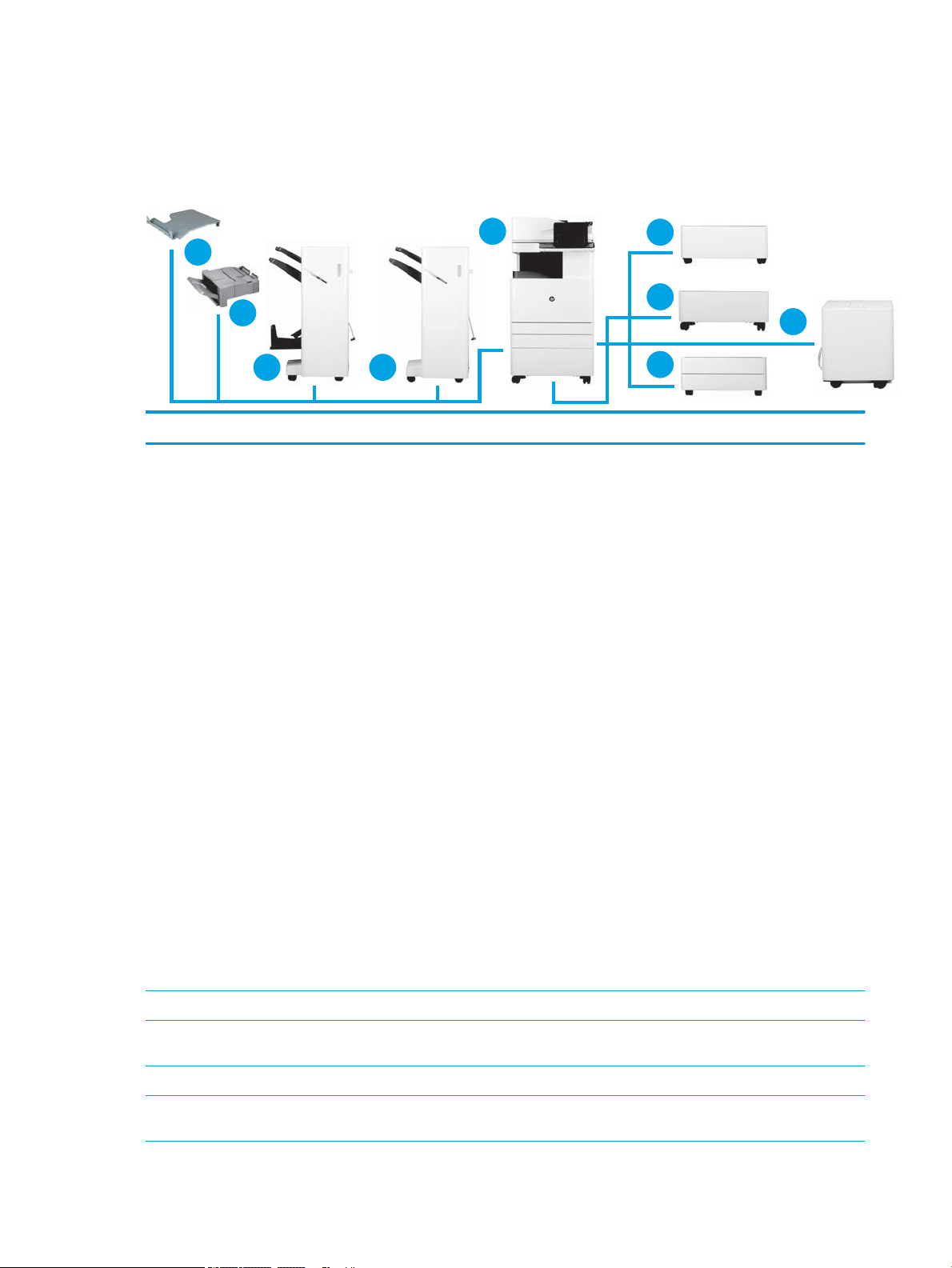
Conguration options
7 6
2
3
4
1
5
8
9
HP Color LaserJet MFP E87640, E87650, E87660 and HP LaserJet MFP E82540, E82550, E82560
Number Component Product number
1 HP Color LaserJet MFP E87640, E87650, E87660
HP LaserJet MFP E82540, E82550, E82560
●
E87640 (40 ppm)
–
–
●
E87650 (50 ppm)
–
–
●
E87660 (60 ppm)
–
–
●
E82540 (40 ppm)
–
–
●
E82550 (50 ppm)
–
–
●
E82560 (60 ppm)
dn models: X3A87A
z models: X3A86A
dn models: X3A90A
z models: X3A89A
dn models: X3A93A
z models: X3A92A
dn models: X3A69A
z models: X3A68A
dn models: X3A72A
z models: X3A71A
–
dn models: X3A75A
–
z models: X3A74A
2 HP LaserJet Department Cabinet Y1G16A
3 HP LaserJet 2000 Sheet High Capacity Input Tray
(HCI) Department
4 HP LaserJet Dual Cassette Feeder (DCF) Department Y1F98A
5 HP LaserJet High Capacity Input Tray Side
Department (sHCI)
Y1G21A
Y1G20A
6 Chapter 2 Conguration ENWW
Page 13

Number Component Product number
6 HP LaserJet Stapler/Stacker Finisher Y1G18A
The following punch kits are available:
●
Y1G10A – HP LaserJet Hole Punch 2/3
Accessory
●
Y1G11A – HP LaserJet Hole Punch 2/4
Accessory
●
Y1G12A – HP LaserJet Hole Punch Swedish
Accessory
●
Y1G14A – HP LaserJet Staple/Stacker Finisher
Rell Staple Cartridge
7 HP LaserJet Booklet Finisher Y1G07A
The following punch kits are available:
●
Y1G10A – HP LaserJet Hole Punch 2/3
Accessory
●
Y1G11A – HP LaserJet Hole Punch 2/4
Accessory
●
Y1G12A – HP LaserJet Hole Punch Swedish
Accessory
●
Y1G13A – HP LaserJet Inner Finisher and
Booklet Maker Finisher Rell Staple Cartridge
●
Y1G14A – HP LaserJet Staple/Stacker Finisher
Rell Staple Cartrdge
8 HP LaserJet Inner Finisher Y1G00A
The following punch kits are available:
●
Y1G02A – HP LaserJet Inner Finisher Hole 2/3
Punch
●
Y1G03A – HP LaserJet Inner Finisher Hole 2/4
Punch
●
Y1G04A - HP LaserJet Inner Finisher Swedish
Punch
●
Y1G13A – HP LaserJet Inner Finisher and
Booklet Maker Finisher Rell Staple Cartridge
9 HP LaserJet Job Separator Department Y1G15A
10 HP LaserJet Paper Tray Heaters Department Y1G22A
NOTE: Not shown in conguration.
The following accessories are also available:
●
Y1G22A#BGJ — HP LaserJet Paper Tray
Heaters Accessory Department (110V)
●
Y1G22A#B19 — HP LaserJet Paper Tray
Heaters Accessory Department (220V)
ENWW Conguration options 7
Page 14

Number Component Product number
11 HP LaserJet Rell Staple Cartridges
12 Re-usable black lift handle install assembly kit. JC82-00538A Kit
●
Y1G13A – HP LaserJet Inner Finisher and
Booklet Maker Finisher Rell Staple Cartridge
●
Y1G14A – HP LaserJet Staple/Stacker Finisher
Rell Staple Cartridge
SAM-JC82-00538A service part
These handles are for use during the initial engine
lifting operations. These are re-usable.
8 Chapter 2 Conguration ENWW
Page 15

3 Worksheets
●
Technical site setup
●
Logistics information
●
Network/printer driver setup
●
Email/Send To conguration
ENWW 9
Page 16

Technical site setup
Table 3-1 Technical site setup worksheet
Yes/No Notes
Will the MFP physically t based
on the operating size
specication where it will be
installed?
Is the oor level? (optional)
Is the oor stable? (optional)
Is there any carpeting or
ooring that requires protection
or reinforcement?
If yes, what is the length of
ooring requiring covering?
Is required power available on a
dedicated circuit in the direct
vicinity?
US, EMEA, and AP require one
power outlet for the printer.
Or, is a power outlet in the direct
vicinity rated to supply the
specic conguration?
❑
Yes
See Specications on page 17.
❑
No
HP recommends that the installation site also support the Serviceability Space
Requirements that allows for 18 inches (457.2 mm) of servicing space on all four sides.
Equipment can be repositioned during the service visit to accommodate the Service Space
Requirements.
❑
Yes
See Specications on page 17, weight specs.
❑
No
❑
Yes
See Specications on page 17, weight specs.
❑
No
❑
Yes
Thick carpeting can cause misalignment between the MFP and Finisher.
❑
No
❑
Yes
The outlet needs to be within 6 feet of planned location of MFP. If a new dedicated circuit
❑
needs to be run, work with customer to complete prior to installation.
No
See Specications on page 17 for more information and check the order to conrm any
specic power requirements.
NOTE: HP recommends installing the printer on its own circuit to prevent possible
interference from other devices.
See Specications on page 17
for more information and check
the order to conrm any specic
power requirements.
Does the room meet the
Environmental Specications?
Is there a network connection in
the direct vicinity?
Will there be direct sunlight on
the MFP?
Is there suicient cooling?
Is there proper air ventilation?
(optional)
Has the customer IT approved
the installation? (optional)
❑
Yes
See Specications on page 17.
❑
No
❑
Yes
Be sure that it is Ethernet.
❑
No
❑
Yes
❑
No
❑
Yes
See Specications on page 17.
❑
No
❑
Yes
❑
No
❑
Yes
❑
No
10 Chapter 3 Worksheets ENWW
Page 17

Table 3-1 Technical site setup worksheet (continued)
Yes/No Notes
Will the customer IT be testing
the products prior to making
them available for general use?
(optional)
If yes, does the customer agree
that the designated installation
location is also acceptable
during the testing period?
(optional)
Do the installation technicians
require security clearance at the
customer location?
If yes, what is the procedure for
obtaining the clearance?
Who will arrange for obtaining
the clearance? (optional)
❑
Yes
❑
No
❑
Yes
❑
No
ENWW Technical site setup 11
Page 18

Logistics information
Table 3-2 Logistics worksheet
Yes/No Remarks/Data
What are the customer’s
“normal” receiving hours?
What is the customer's preferred
delivery time? (optional)
Would "after hours" be preferred
at an additional charge?
(optional)
Is a certicate of insurance
required?
Are there any labor union
constraints or requirements?
Is there a truck height receiving
dock? Height restrictions?
What is the height from ground to
dock platform?
Does the receiving dock have
dock levelers? (optional)
Does the receiving dock have a
dock plate? (optional)
❑
Yes
❑
No
❑
Yes
❑
No
❑
Yes
❑
No
❑
Yes
❑
No
❑
Yes
❑
No
❑
Yes
❑
No
Is a lift gate truck required?
If no dock available and ground
delivery is required, will the area
require special covering?
Is delivery area tractor-trailer
accessible?
If no, what is the maximum size
truck accessibility?
Is there room to unpack the
system on the receiving dock?
❑
Yes
❑
No
❑
Yes
❑
No
❑
Yes
❑
No
❑
Yes
❑
No
12 Chapter 3 Worksheets ENWW
Page 19

Table 3-2 Logistics worksheet (continued)
Yes/No Remarks/Data
Is the delivery of the unit on the
same oor as receiving? If no, is
an elevator used? Please identify
below.
If no elevator is to be used, how is
the unit to be delivered?
What is the distance in meters
from the receiving area to the
planned copier location?
(optional)
Do the dimensions of doorways
and hallways along the delivery
path meet minimum system
dimensional requirements?
Is there a clear path to the
planned delivery location?
Is the copier room level with
oor?
If no, is there a ramp?
Are their enough people to lift the
engine assembly? (required)
❑
Yes
Note that stair climbers are not currently approved for moving MFP printers. If needed,
❑
❑
❑
❑
❑
❑
❑
❑
❑
lift or hoist the MFP printers in their crates and keep them in an upright position.
No
Yes
The box for the main MFP unit requires a doorway opening of 765 mm (30.1 in).
No
See Size and weight specications on page 18 for complete information about box
dimensions.
Yes
No
Yes
No
Yes
The engine assembly is heavy and requires four people to lift onto the stand or DCF. HP
recommends using the black lift assist handles when lifting the device.
No
Is there a possibility to discard
packaging materials at customer
site? (optional)
❑
Yes
❑
No
ENWW Logistics information 13
Page 20

Network/printer driver setup
(If done by an HP technician)
Table 3-3 Network/printer driver worksheet
Yes/No Remarks/Data
What network topology is in use?
What operating system will be
used on the server?
What operating system will be
used on the clients?
Is DHCP/BOOTP in use?
If no, what TCP/IP address will be
used for the MFP?
What version of TCP/IP is used in
the deployment?
If no, what subnet mask address
will be used for the MFP?
If no, what default gateway
address will be used for the MFP?
If no, does a host name need to
be congured (+name)?
(optional)
❑
Yes
❑
No
❑
Yes
❑
No
14 Chapter 3 Worksheets ENWW
Page 21

Email/Send To conguration
NOTE: Optional: Complete only if the hardware technician is responsible for conguring the Email/Send To
features.
Table 3-4 Email/Send To conguration worksheet
Yes/No Remarks/Data
Is Active Directory, Novell, NTLM
or something else in use?
(optional)
Is DNS in use? (optional)
If yes, what is the domain name?
(optional)
What type of SMTP server is in
use? (MS Exchange, Lotus Notes,
etc.) (optional)
Or, if an ISP mail server is being
used, what is the IP or host name
to the server? (optional)
On what OS is the SMTP server
installed? (optional)
Is LDAP installed on the same
server as the SMTP server?
(optional)
If not, what is the OS of the LDAP
server? (optional)
What is the TCP/IP address of the
SMTP server or host name?
What is the TCP/IP address of the
LDAP server?
❑
Yes
❑
No
❑
Yes
❑
No
❑
Yes
❑
No
What is the port number that
LDAP uses?
What is the search root of the
LDAP server?
Is Send to Folder supported /
required?
If yes, what OS are the shared
folders on?
What type of fax is required to be
supported?
Analog, LAN, Internet?
If LAN fax is required, is there a
LAN fax server available?
If Internet fax is required, is there
a subscription to an Internet fax
service?
❑
Yes
❑
No
❑
Yes
❑
No
❑
Yes
❑
No
ENWW Email/Send To conguration 15
Page 22

16 Chapter 3 Worksheets ENWW
Page 23

4 Specications
●
Size and weight specications
●
System conguration dimensions
●
Operational clearance space requirements
●
Environmental specications
●
Power requirements
ENWW 17
Page 24

Size and weight specications
Table 4-1 Individual unit weight and size information
Description Master Carton Size / Gross Weight (boxed) Net Weight
HP Color LaserJet MFP E87640, E87650,
E87660
HP LaserJet MFP E82540, E82550, E82560 dn models:
HP LaserJet Dual Cassette Feeder (DCF)
Department
HP LaserJet Cabinet Department 585 mm (23
HP LaserJet 2000 Sheet High Capacity Input
Tray (HCI) Department
1
Width Depth Height Weight (boxed)
dn
, du models:
585 mm (23
in)
z models:
585 mm (23
in)
585 mm (23
in)
z models:
585 mm (23
in)
585 mm (23
in)
in)
575 mm (23
in)
dn
, du models:
764.3 mm
(30.
1 in)
z models:
764.3 mm
(30.1 in
)
dn models:
764.3 mm
(30.1 in)
z models:
764.3 mm
(30.1 in
)
706.8 mm
(27.8 in)
706.8 mm
(27.8 in)
706.8 mm
(27.8 in)
dn
, du models:
883.7 mm
(34.8
in)
z models: 932.2
mm (36.7 in)
dn models:
883.7 mm
(34.8 in)
z models: 932.2
mm (36.7 in)
254 mm (10 in) 24.6 kg (54.2
254 mm (10 in) 15 kg (33.07
254 mm (10 in) 33.8 kg (74.4
dn
, du models:
131.6 kg
(290.2 lb)
z models:
131.6 kg
(290.2 lb
dn models:
114.5 k
g
(252.5 lb)
z models:
114.5 k
g
(252.5 lb)
lb)
lb)
lb)
models: 113.1 kg (249.3 lb)
dn
du models: 100.9 kg (224.44 lb)
z models: 113.1 kg (249.3 lb)
dn, du models: 95.6 kg
(210.8 lb)
z models: 95.6 kg (210.8 lb)
21 kg (46.3 lb)
11.9 kg (26.3 lb)
28.3 (62.48 lb)
HP LaserJet High Capacity Input Tray Side (sHCI)
Department
HP LaserJet Inner Finisher 458 mm (18
HP LaserJet Booklet Finisher 1003.3 mm
HP LaserJet Stapler/Stacker Finisher 1003.3 mm
1
Weight and size information is approximate and for reference only.
412.5 mm
(16.25 in)
in)
(39.75 in)
(39.75 in)
362 mm (14
in)
491 mm (19.3
in)
673 mm
(26.75 in)
673 mm
(26.75 in)
533.4 mm (21
in)
173 mm (6.8 in) 72.6 kg (33 lb) 18.2 kg (40.1 lb)
587.5 mm (23.5
in)
587.5 mm (23.5
in)
23.3 kg (51.4
lb)
86.8 kg
(191.36 lb)
61.6 kg (135.7
lb)
20.05 kg (44.22 lb)
62 kg (136.68 lb)
194 kg (88 lb)
18 Chapter 4 Specications ENWW
Page 25

System conguration dimensions
ENWW System conguration dimensions 19
Page 26
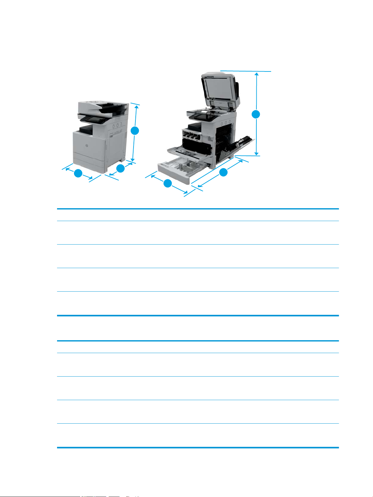
Base printer conguration
2
1
3
2
3
1
The base conguration includes the following components:
Table 4-2 Dimensions of the E87640, E87650, E87660
Normal operating dimensions Maximum operating dimensions
1. Height dn models: 932.2 mm (36.7 in)
z models: 932.2 mm (36.7 in)
2. Depth dn models: 771.1 mm (30.3 in)
z models: 771.1 mm (30.3 in)
3. Width dn models: 585 mm (23 in)
z models: 585 mm (23 in)
Weight dn models: 113.1 kg (249.3 lb)
z models: 113.1 kg (249.3 lb)
dn models: 775 mm (36.1 in)
z models: 775 mm (36.1 in)
dn models: 1676 mm (66 in)
z models: 1676 mm (66 in)
dn models: 1134 mm (47 in)
z models: 1134 mm (47 in)
Table 4-3 Dimensions of the E82540, E82550, E82560
Normal operating dimensions Maximum operating dimensions
1. Height dn models: 932.2 mm (36.7 in)
z models: 932.2 mm (36.7 in)
2. Depth dn models: 771.1 mm (30.3 in)
z models: 771.1 mm (30.3 in)
3. Width dn models: 585 mm (23 in)
z models: 585 mm (23 in)
dn models: 775 mm (36.1 in)
z models: 775 mm (36.1 in)
dn models: 1676 mm (66 in)
z models: 1676 mm (66 in)
dn models: 1134 mm (47 in)
z models: 1134 mm (47 in)
Weight dn models: 95.6 kg (210.8 lb)
z models: 95.6 kg (210.8 lb)
20 Chapter 4 Specications ENWW
Page 27
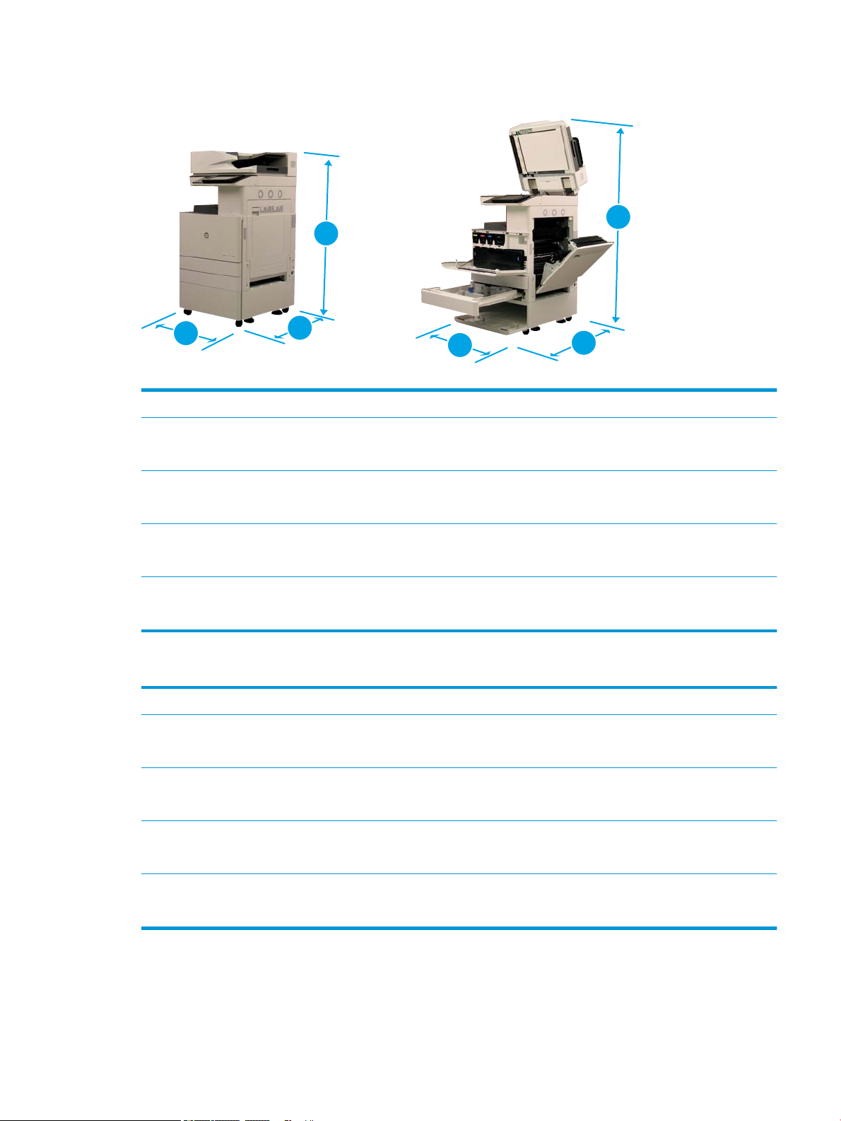
Printer with cabinet conguration
3
2
1
3
1
2
Table 4-4 Dimensions of the E87640, E87650, E87660
Normal operating dimensions Maximum operating dimensions
1. Height dn models: 1186.2 mm (46.7 in)
z models: 1186.2 mm (46.7 in)
2. Depth dn models: 771.1 mm (30.3 in)
z models: 771.1 mm (30.3 in)
3. Width dn models: 585 mm (23 in)
z models: 585 mm (23 in)
Weight dn models: 125 kg (275.6 lb)
z models: 125 kg (275.6 lb)
Table 4-5 Dimensions of the E82540, E82550, E82560
Normal operating dimensions Maximum operating dimensions
1. Height dn models: 1186.2 mm (46.7 in)
z models: 1186.2 mm (46.7 in)
2. Depth dn models: 771.1 mm (30.3 in)
z models: 771.1 mm (30.3 in)
3. Width dn models: 585 mm (23 in)
dn models: 1029 mm (46.1 in)
z models: 1029 mm (46.1 in)
dn models: 1676 mm (66 in)
z models: 1676 mm (66 in)
dn models: 1134 mm (47 in)
z models: 1134 mm (47 in)
dn models: 1029 mm (46.1 in)
z models: 1029 mm (46.1 in)
dn models: 1676 mm (66 in)
z models: 1676 mm (66 in)
dn models: 1134 mm (47 in)
z models: 585 mm (23 in)
Weight dn models: 107.5 kg (237.1 lb)
z models: 107.5 kg (237.1 lb)
z models: 1134 mm (47 in)
ENWW System conguration dimensions 21
Page 28
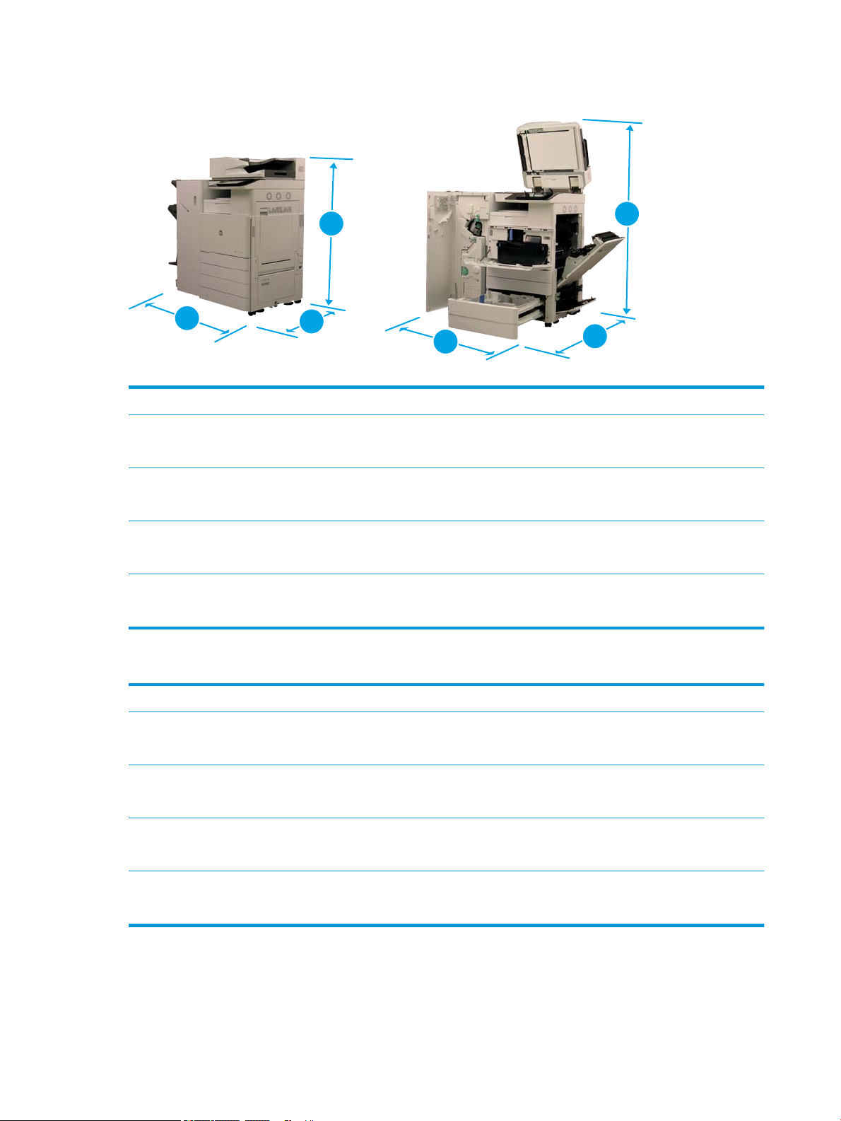
Printer with booklet nisher conguration
3
2
1
3
1
2
Table 4-6 Dimensions of the E87640, E87650, E87660
Normal operating dimensions Maximum operating dimensions
1. Height dn models: 1186.2 mm (46.7 in)
z models: 1186.2 mm (46.7 in)
2. Depth dn models: 771.1 mm (30.3 in)
z models: 771.1 mm (30.3 in)
3. Width dn models: 1588.3 mm (62.75 in)
z models: 1588.3 mm (62.75 in)
Weight dn models: 196.1 kg (432.28 lb)
z models: 196.1 kg (432.28 lb)
Table 4-7 Dimensions of the E82540, E82550, E82560
Normal operating dimensions Maximum operating dimensions
1. Height dn models: 1186.2 mm (46.7 in)
z models: 1186.2 mm (46.7 in)
2. Depth dn models: 1774.1 mm (70.05 in)
z models: 1774.1 mm (70.05 in)
3. Width dn models: 1588.3 mm (62.75 in)
dn models: 1029 mm (46.1 in)
z models: 1029 mm (46.1 in)
dn models: 1676 mm (66 in)
z models: 1676 mm (66 in)
dn models: 2137.3 mm (86.75 in)
z models: 2137.3 mm (86.75 in)
dn models: 1029 mm (46.1 in)
z models: 1029 mm (46.1 in)
dn models: 2679.3 mm (105.75 in)
z models: 2679.3 mm (105.75 in)
dn models: 2137.3 mm (86.75 in)
z models: 1588.3 mm (62.75 in)
Weight dn models: 178.6 kg (393.78 lb)
z models: 178.6 kg (393.78 lb)
z models: 2137.3 mm (86.75 in)
22 Chapter 4 Specications ENWW
Page 29
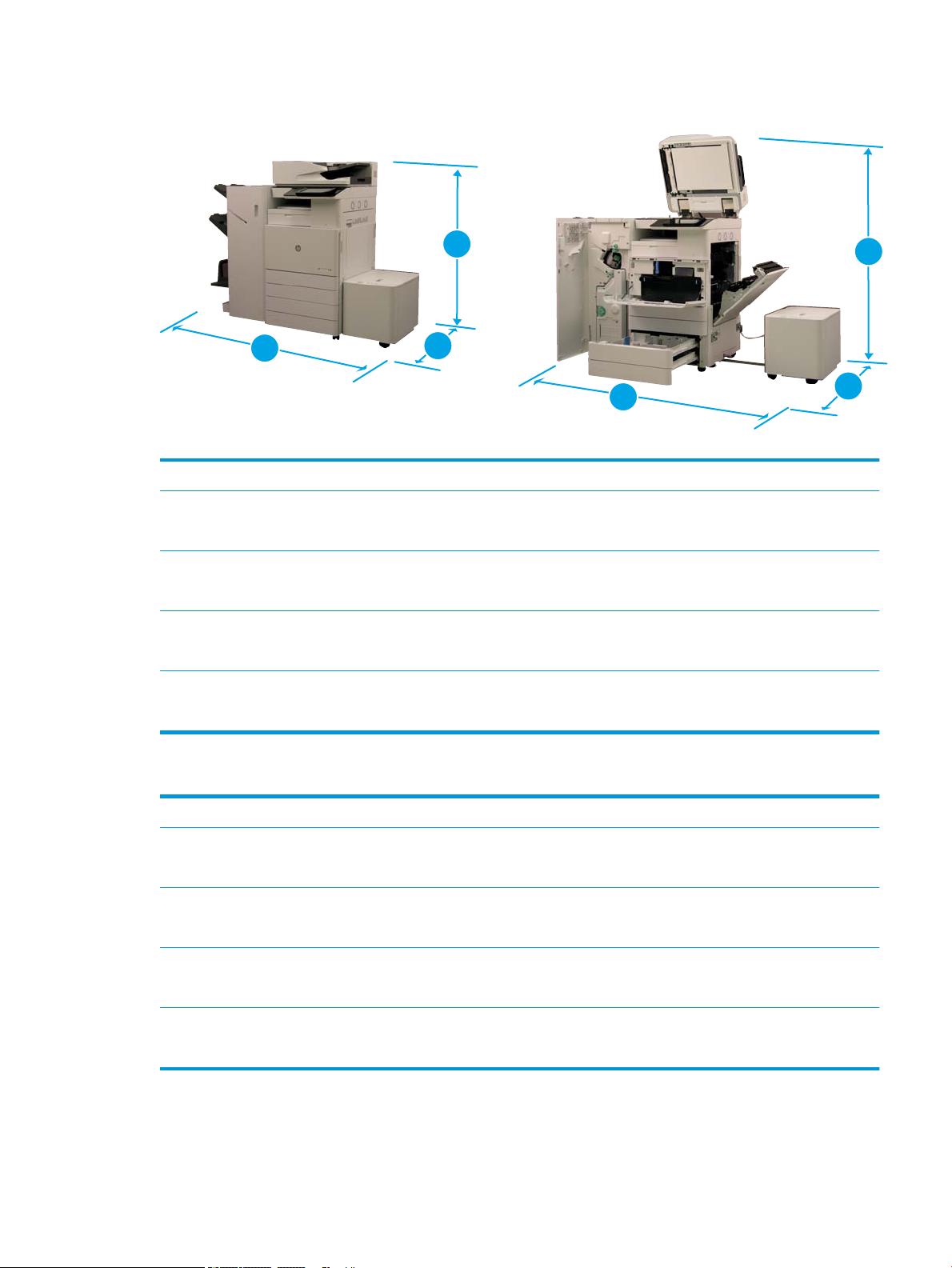
Printer with booklet nisher and side HCI conguration
3
2
1
3
2
1
Table 4-8 Dimensions of the E87640, E87650, E87660
Normal operating dimensions Maximum operating dimensions
1. Height dn models: 1186.2 mm (46.7 in)
z models: 1186.2 mm (46.7 in)
2. Depth dn models: 771.1 mm (30.3 in)
z models: 771.1 mm (30.3 in)
3. Width dn models: 2000.3 mm (79 in)
z models: 2000.3 mm (79 in)
Weight dn models: 216.16 kg (476.5 lb)
z models: 216.16 kg (476.5 lb)
Table 4-9 Dimensions of the E82540, E82550, E82560
Normal operating dimensions Maximum operating dimensions
1. Height dn models: 1186.2 mm (46.7 in)
z models: 1186.2 mm (46.7 in)
2. Depth dn models: 1774.1 mm (70.05 in)
z models: 1774.1 mm (70.05 in)
3. Width dn models: 2000.3 mm (79 in)
dn models: 1029 mm (46.1 in)
z models: 1029 mm (46.1 in)
dn models: 1676 mm (66 in)
z models: 1676 mm (66 in)
dn models: 2549.3 mm (103 in)
z models: 2549.3 mm (103 in)
dn models: 1029 mm (46.1 in)
z models: 1029 mm (46.1 in)
dn models: 2679.3 mm (105.75 in)
z models: 2679.3 mm (105.75 in)
dn models: 2549.3 mm (103 in)
z models: 2000.3 mm (79 in)
Weight dn models: 198.65 kg (438 lb)
z models: 198.65 kg (438 lb))
ENWW System conguration dimensions 23
z models: 2549.3 mm (103 in)
Page 30

Operational clearance space requirements
Make sure the printer is installed in an area with enough space around the device for proper service access and
ventilation. The ADF when fully opened requires 20 inches (508 mm) above the level of the top. The back of
copier and wall needs proper ventilation.
The following space must be provided around the machine to assure machine performance and proper
operations. If any option is installed, provide the additional space for installing it.
NOTE: HP recommends that 18 inches (457.2 mm) be added to the printer sides and front to make sure there
is suicient space to open doors and covers.
●
Rear clearance space: 18 inches (457.2 mm)
●
Left clearance space: 18 inches (457.2 mm)
●
Right clearance space: 18 inches (457.2 mm)
24 Chapter 4 Specications ENWW
Page 31

Environmental specications
Table 4-10 Operating-environment specications
Environment Recommended Allowed
Temperature 15° to 30°C (59° to 86°F) 15° to 30°C (59° to 86°F)
Relative humidity 20% to 80% (RH) 20% to 80% (RH)
NOTE: The operating environment of the printer must remain stable.
ENWW Environmental specications 25
Page 32

Power requirements
Table 4-11 Power requirements
Item Specication
Input Voltage (Europe) AC 220—240 V (+/- 10%)
Input Voltage (USA) AC 110—127 V (+/- 10%)
Input Voltage (AP) AC 220—240 V (+/- 10%)
Rated Frequency 50/60 Hz (+/- 3%)
Table 4-12 Power consumption
Item Specication
Ready Less than 300 Wh
Normal operation Less than 900 Wh
Max/Peak Less than 1300 Wh
Sleep Less than 2.0 Wh
TEC
Default Sleep Delay Time 2 minutes
Maximum Sleep Delay Time
●
E87640: 2.1 kWh
●
E87650: 2.717 kWh
●
E87660: 3.05 kWh
●
E82540: 2.1 kWh
●
E82550: 2.717 kWh
●
E82560: 3.1 kWh
●
E82540, E82550: 60 minutes
●
E82560: 120 minutes
●
E87640, E87650, E87660: 60 minutes
26 Chapter 4 Specications ENWW
Page 33

5 Staging
●
Staging checklists
●
Unboxing and basic assembly
●
Initial supplies installation
●
Initial power on
●
Engine adjustments and tests
●
Prepare for shipment to customer location
●
Repack (from customer site)
ENWW 27
Page 34

Staging checklists
NOTE: Stagers must take appropriate training and download and utilize all installation guides in order to do the
following steps correctly. Staging is typically performed at an o site location.
NOTE: Assemblers must be trained and qualied/certied to perform this activity.
Table 5-1 Staging (minimum 30 min + options)
❑
Unbox and inventory miscellaneous items – 4 person lift (10 mins).
❑
Unbox the tray or cabinet (5 mins).
❑
Unbox the engine (5 mins).
❑
Place the engine on the lower accessory, if ordered – 4 person lift (2 mins).
❑
Remove the shipping tape and scanner lock (5 mins).
❑
Unpackage and install the toner cartridge(s) (2 mins).
Table 5-2 Assembly and testing (minimum 55 mins + options)
❑
Attach the paper handling or other accessories (based on conguration).
❑
Install the imaging unit(s) (5 mins).
❑
Adjust the tray paper guides to the appropriate size for the account.
❑
Load the paper trays and lock the rear guides (5 mins).
❑
Connect the power and LAN cables and turn on the main switch.
❑
Power on and wait for the initial screen (2 mins).
❑
Perform the Late Point Dierentiation Conguration (LPDC) (3 min).
NOTE: LPDC will be automatically set up after power on. If this fails or no internet is available, the LPDC information will need to be
installed manually.
❑
Select a language and set the date/time (1 min)
❑
Update to latest rmware (up to 20 min)
CAUTION: All accessories need to be attached to the device before upgrading rmware. After installing accessories the rmware
must be updated to make sure the printer rmware is compatible with the accessory.
❑
Print the conguration and demo pages (2 min)
❑
Perform a basic functionality test (10 minutes) – test print, copy, and each accessory
❑
Disassemble the accessories and prepare the printer for transportation (3 min)
28 Chapter 5 Staging ENWW
Page 35
Unboxing and basic assembly
x 2
For HP Color LaserJet MFP E87640, E87650, E87660 products and the Y1F99A HP LaserJet 2000-sheet HCI.
Click here to view video of this procedure.
For HP LaserJet MFP E82540, E82550, E82560 products and the Y1G16A HP LaserJet Cabinet
Click here to view a video of this procedure..
HP Color LaserJet E87640, E87650, E87660 or HP LaserJet E82540, E82550, E82560 engine
1. Open the box, then remove the packing materials and accessories packed on top of the engine.
2. Lift the box from the engine, then pull down the plastic bag around the engine.
HP LaserJet Dual Cassette Department Feeder (DCF) and HP LaserJet Department Cabinet or 2000-sheet HCI
1. Open the box, and then remove all accessories, manuals, and packing materials on top of the DCF/Cabinet
or 2000-sheet HCI.
CAUTION: The DCF/Cabinet or 2000-sheet HCI requires two people to lift.
2. Tilt the shipping box on its side, and then carefully remove the DCF/Cabinet or 2000-sheet HCI from the
box.
3. Remove the DCF/Cabinet or 2000-sheet HCI from its shipping bag, and then remove all tape and packing
materials from the exterior of the DCF and the trays.
IMPORTANT: Two wingnuts are taped to the top of the 2000-sheet HCI/Cabinet chassis. Retain the
wingnuts/alignment pins for installing the engine to the DCF/Cabinet and 2000-sheet HCI.
HP Job Separator
▲
Unpack the job separator.
HP LaserJet Paper Tray Heaters
▲
Verify the contents of the heaters, and then leave them boxed for the service technician or installer.
ENWW Unboxing and basic assembly 29
Page 36

Engine preparation
For HP Color LaserJet MFP E87640, E87650, E87660: Click here to view a video of this procedure.
For HP LaserJet MFP E82540, E82550, E82560: Click here to view a video of this procedure.
CAUTION: The engine assembly is heavy and requires four people to lift.
1. Remove the packaging, such as foam and plastic.
2. Leave the tape on the engine intact.
Stacking
For HP Color LaserJet MFP E87640, E87650, E87660: Click here to view a video of this procedure.
For HP LaserJet MFP E82540, E82550, E82560: Click here to view a video of this procedure.
HP Color LaserJet MFP E87640, E87650, E87660 and HP LaserJet MFP E82540, E82550, E82560
CAUTION: The engine assembly is heavy and requires four people to lift.
Stacking the engine on the DCF/Cabinet or HCI
1. Install the two black re-usable lifting handles in the hand-holds on the left-side of the printer.
2. Open two lift bars on the right-side of the printer.
30 Chapter 5 Staging ENWW
Page 37

3. Carefully lift the engine assembly from each corner, align the engine to the locator pins and connector on
the DCF/2000-sheet HCI, and then carefully lower the engine onto the DCF/2000-sheet HCI.
4. Install two thumbscrews for the 2000-sheet HCI and cabinet.
5. Remove the scanner lock screw.
CAUTION: The scanner lock screw must be removed prior to powering on the printer.
Staging the side HCI (sHCI)
Click here to view a video of this procedure.
1. Cut the top of the container.
2. Open container for the cabinet.
3. Remove the shipping foam that includes rail, alignment bracket, additional hardware, and screws. Set these
aside.
CAUTION: The sHCI requires two people to lift out of the container.
4. Tilt carton on its side to allow easier removal of the cabinet from carton.
5. Slide the sHCI out of the carton.
6. Remove plastic bag from the sHCI.
7. Rotate the sHCI to its upright position with casters on the bottom.
8. Remove all shipping material and shipping tape from sHCI.
9. Open top of the sHCI and remove the shipping foam and shipping tape.
NOTE: To remove shipping foam, lift from the bottom of the foam and lift straight up to remove.
ENWW Unboxing and basic assembly 31
Page 38

Finishers
b
x 4
a
x 6
c
x 1
62kg
137lb
HP LaserJet Inner nisher
Click here to view video of this procedure.
▲
Unpack the inner nisher.
NOTE: Some parts may be buried in the packing foam.
HP LaserJet Booklet Finisher
Click here to view a video of this procedure.
▲
Unpack the booklet nisher.
NOTE: Some parts may be buried in the packing foam.
HP LaserJet Stapler/Stacker Finisher
Click here to view a video of this procedure.
▲
Unpack the stapler/stacker nisher.
NOTE: Some parts may be buried in the packing foam.
32 Chapter 5 Staging ENWW
Page 39

x 7
x 13
c
x 4
b
a
ENWW Unboxing and basic assembly 33
Page 40

Initial supplies installation
2
1
Install toner
HP Color LaserJet MFP E87640, E87650, E87660
Click here to view a video of this procedure.
NOTE: Follow the instructions on the inside of the printer.
For the latest information on how to install the toner cartridges click here
Click here to view a video for this procedure.
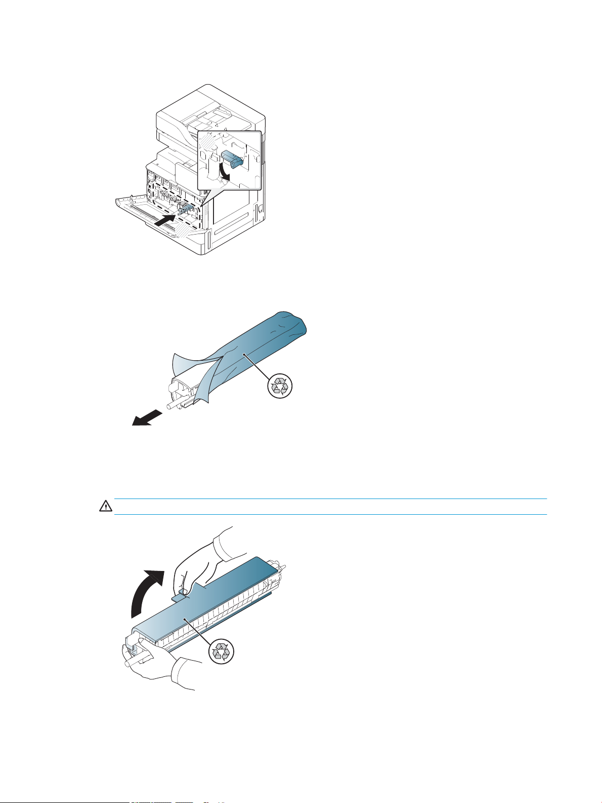
1.
2.
34 Chapter 5 Staging ENWW
Page 41
3.
4. Shake the toner cartridge vigorously from side to side at least ten times.
–
Rotate the toner cartridge 90 degrees until the blue top handle is facing away from you, and repeat
the shaking process.
–
Rotate the toner cartridge 90 degrees until the blue top handle is facing down and the shutter is
facing up, and repeat the shaking process.
–
Rotate the toner cartridge 90 degrees until the blue handle is facing toward you, and repeat the
shaking process.
ENWW Initial supplies installation 35
Page 42

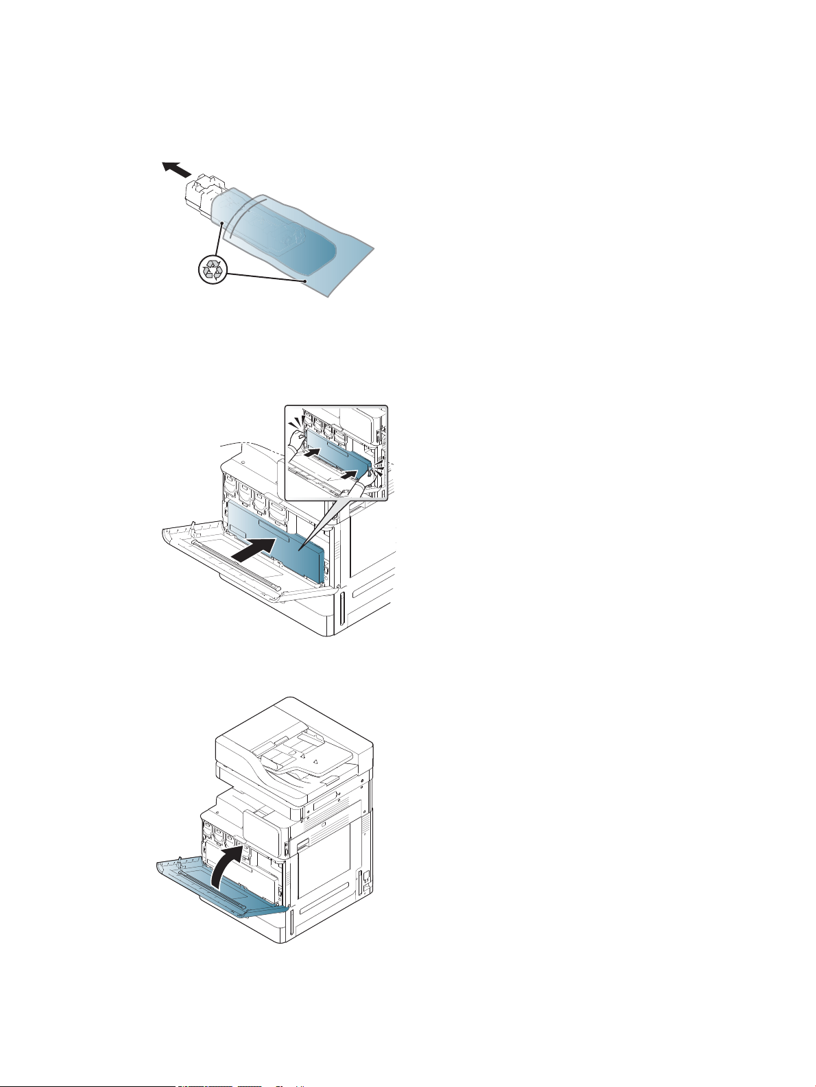
5.
1
2
21
6.
7.
36 Chapter 5 Staging ENWW
Page 43
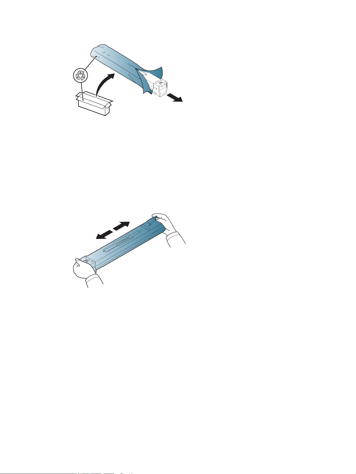
8.
HP LaserJet MFP E82540, E82550, E82560
Click here to view a video of this procedure.
NOTE: Follow the instructions on the inside of the printer.
1.
ENWW Initial supplies installation 37
Page 44

2.
1
2
3. Vigorously shake side-to-side the toner cartridge to distribute toner throughout the toner container (about
10 times).
4.
38 Chapter 5 Staging ENWW
Page 45

5.
1
2
6.
ENWW Initial supplies installation 39
Page 46

7.
40 Chapter 5 Staging ENWW
Page 47

Initial power on
1
2
Install imaging drum (HP Color LaserJet MFP E87640, E87650, E87660)
. Click here to view a video for this procedure.
NOTE: The technician must be trained and qualied/certied to perform this activity.
CAUTION: To prevent damage to the printer, use only the power cord that is provided with the printer.
CAUTION: The scanner lock screw must be removed prior to powering on the printer.
A label with the printer voltage rating is located on the back of the printer.
NOTE: Make sure that the power source is adequate for the printer voltage rating. The voltage rating is on the
printer label. The printer uses either 110-127 Vac or 220-240 Vac and 50/60 Hz.
1. Remove the shipping material from each of the developing units by pulling the red tape down o the
engine and then pull straight out of the developing unit.
CAUTION: Ensure all shipping tape is removed.
ENWW Initial power on 41
Page 48
2. Lower the drum lock lever for each color location.
1
2
3. Remove the imaging drum from packaging.
4. Remove the orange plastic cover by ipping image drum over and releasing the two orange tabs at both
ends. Remove in the direction of the arrow.
CAUTION: Do not touch the green drum.
42 Chapter 5 Staging ENWW
Page 49

5. Support the imaging drum with one hand on the bottom and one hand holding the handle on the front. Do
1
2
not use the waste toner connection as a handle.
NOTE: Guide on the right top side of image drum that aligns with a guide inside the engine.
6. Slide into printer using the guide.
7. Rotate lower lever up to locking position (about 90°)
ENWW Initial power on 43
Page 50
8. Remove toner collection unit from shipping bag.
9. Install the TCU by pushing in on both sides until the tabs snap into place.
10. Close the front door.
44 Chapter 5 Staging ENWW
Page 51

Install imaging drum (HP LaserJet MFP E82540, E82550, E82560)
1
2
Click here to view a video of this procedure.
NOTE: The technician must be trained and qualied/certied to perform this activity.
CAUTION: To prevent damage to the printer, use only the power cord that is provided with the printer.
CAUTION: The scanner lock screw must be removed prior to powering on the printer.
A label with the printer voltage rating is located on the back of the printer.
NOTE: Make sure that the power source is adequate for the printer voltage rating. The voltage rating is on the
printer label. The printer uses either 110-127 Vac or 220-240 Vac and 50/60 Hz.
1. Open the right door by grasping latch and releasing in the direction of the arrow.
ENWW Initial power on 45
Page 52
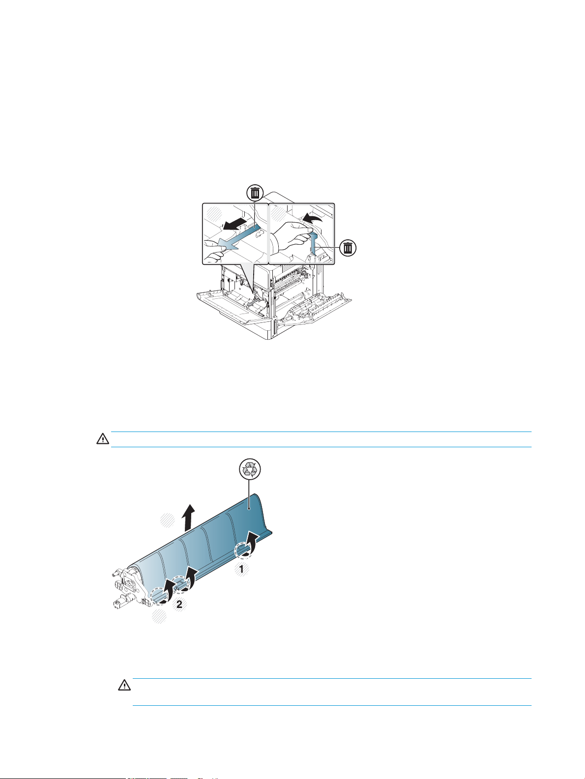
2. Remove red tape pull straight in direction of the arrow. Remove second shipping material from the
1 2
4
3
developing unit by pulling the red tape down o the engine and then pull straight out of the developing
unit.
3. Remove image drum from shipping bag. Remove orange shipping material from drum, release tabs on
center (callout 2) and at each ends (callout 1,3) to release orange shipping material (callout 4).
CAUTION: Do not touch the green drum and reduce its exposure to light.
4. Underneath, there is a plastic handle located in the middle to assist in the installation into engine.
▲
Install image drum in the upper opening in the engine.
CAUTION: Verify the guide on top of the imaging drum is properly aligned to the guide inside the
engine before pushing. If it is not, the drum will be scratched.
46 Chapter 5 Staging ENWW
Page 53

5. Screw in thumbscrew located on the left side and rotate the developing unit lock lever up.
1 2
6. Close the right door.
ENWW Initial power on 47
Page 54

7. Remove Toner Collection Unit from shipping bag.
8. Install by pushing in on both sides until the tabs snap into place.
9. Close the front door.
48 Chapter 5 Staging ENWW
Page 55
Engine adjustments and tests
Load paper in trays and input devices
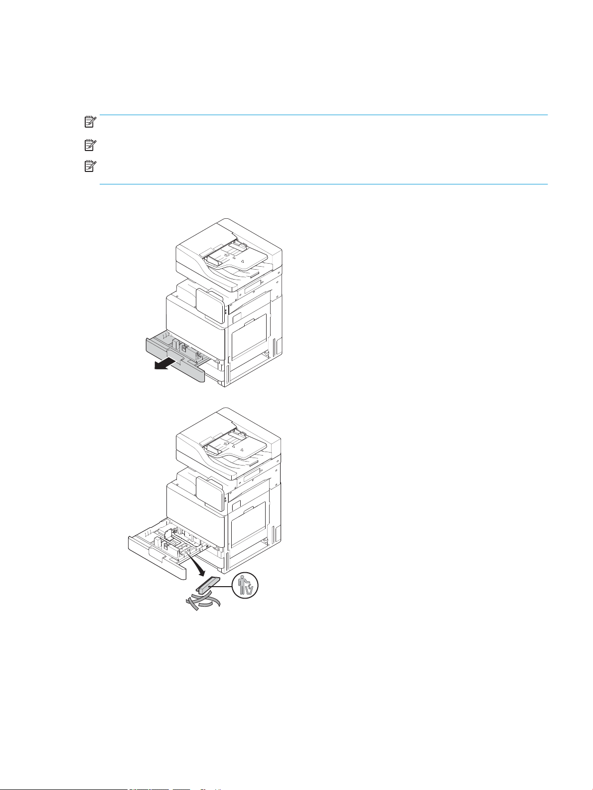
NOTE: Make sure all shipping tape and other packing materials are remove from the tray before loading paper.
NOTE: Make sure to keep the paper tray labels for installation on the tray front panel.
NOTE: The trays default conguration is set to A4 paper size. If using letter paper size, adjust the guides for
letter size.
Loading paper in trays on the printer
1.
2.
ENWW Engine adjustments and tests 49
Page 56

3.
1
2
4.
5.
50 Chapter 5 Staging ENWW
Page 57

6.
7.
ENWW Engine adjustments and tests 51
Page 58

Loading paper into the HCI (bottom)
1.
52 Chapter 5 Staging ENWW
Page 59

2.
ENWW Engine adjustments and tests 53
Page 60

Loading paper into the sHCI
1.
2.
54 Chapter 5 Staging ENWW
Page 61

3.
ENWW Engine adjustments and tests 55
Page 62

Prepare for shipment to customer location
Table 5-3 Transportation preparation
❑
Power down and disconnect all nishing devices.
❑
Separate the engine and input/output devices.
❑
For long distance transportation, reinstall the scanner lock screw.
❑
Leave the attachment brackets in place.
NOTE: If the attachment brackets for the nisher are left in place, be careful not to damage them when securing the device during
transport.
NOTE: If attachment hardware for sHCI is left in place, the attachment rail must be secured under the device by using packing tape
at both ends.
❑
Retract stabilizer feet on bottom of the units for move.
❑
Protect the casters.
❑
Reinstall the shipping lock on the Booklet Finisher.
❑
HP recommends placing the nishers on pallet for transportation.
❑
Arrange for local shipping.
❑
Blanket wrap the engines and make sure they are properly strapped to the truck.
❑
Whenever rolling over any rough surface (asphalt, cobble stones, and other rough surface) lay down 4 x 8 sheets of 1/4 in hardboard.
❑
When transporting across gaps use appropriate support devices to make sure the transportation of the printer is smooth.
❑
Verify truck shipment requirements.
❑
Verify securing requirements.
56 Chapter 5 Staging ENWW
Page 63

Repack (from customer site)
Local move
Table 5-4 Transportation preparation
❑
Power down and disconnect all nishing devices.
❑
Separate the engine and input/output devices.
❑
For long distance transportation, reinstall the scanner lock screw.
❑
Leave the attachment brackets in place.
NOTE: If the attachment brackets for the nisher are left in place, be careful not to damage them when securing the device during
transport.
NOTE: If attachment hardware for sHCI is left in place, the attachment rail must be secured under the device by using packing tape
at both ends.
❑
Retract stabilizer feet on bottom of the units for move.
❑
Lock the scanner and lock the booklet nisher with support rod.
❑
Protect the casters.
❑
Reinstall the shipping lock on the Booklet Finisher.
❑
HP recommends placing the nishers on pallet for transportation.
❑
Arrange for local shipping.
❑
Blanket wrap the engines and make sure they are properly strapped to the truck.
❑
Whenever rolling over any rough surface (asphalt, cobble stones, and other rough surface) lay down 4 x 8 sheets of 1/4 in hardboard.
❑
When transporting across gaps use appropriate support devices to make sure the transportation of the printer is smooth.
Long distance move
NOTE: If the product will be transported more than 500 miles, transported by air, or placed in storage more
than 30 days, contact the factory for recommendations.
Table 5-5 Long distance move
❑
Air freight
❑
Power down and disconnect all nishing devices.
❑
Separate the engine and input/output devices.
❑
For long distance transportation, reinstall the ADF scanner lock screw.
❑
Verify truck shipment requirements.
❑
Verify securing requirements.
❑
Long distance truck shipment
ENWW Repack (from customer site) 57
Page 64

Table 5-5 Long distance move (continued)
❑
Leave the attachment brackets in place.
NOTE: If the attachment brackets for the nisher are left in place, be careful not to damage them when securing the device during
transport.
NOTE: If attachment hardware for sHCI is left in place, the attachment rail must be secured under the device by using packing tape
at both ends.
❑
Retract stabilizer feet on bottom of the units for move.
❑
Install the scanner lock and the support lock for the booklet nisher.
❑
Protect the casters.
❑
Reinstall the shipping lock on the Booklet Finisher.
❑
HP recommends placing the nishers on pallet for transportation.
❑
For long distance transportation, HP recommends crating the printers and accessories or using pallets with heavy padding.
❑
Arrange for long distance shipping.
❑
Whenever rolling over any rough surface (asphalt, cobble stones, and other rough surface) lay down 4 x 8 sheets of 1/4 in hardboard.
❑
When transporting across gaps use appropriate support devices to make sure the transportation of the printer is smooth.
❑
Verify truck shipment or air freight requirements.
❑
Verify securing requirements.
58 Chapter 5 Staging ENWW
Page 65

6 Late point dierentiation conguration (LPDC)
●
LPDC installation steps
NOTE: The LPDC procedure has two components that must be performed by a trained person during the device
install, staging or setup process.
NOTE: Up to a 24 hour delay from the time the unit is shipped to when the license becomes available in the
cloud. You will be unable to download the license to the device until the license is available.
ENWW 59
Page 66

LPDC installation steps
Automatically download and transfer speed license
1. Connect the device to the power source but do NOT connect the network cable yet.
2. Turn on the device, wait for the Setup Wizard to display, and then congure each setting.
3. Allow the device to nalize the initialization and internal communications.
4. Print a conguration page and make sure that the device is working.
5. Manually update the device rmware using the USB ash drive but do NOT connect the network cable.
NOTE: Do not skip this step.
6. Make sure all accessories are installed before upgrading rmware. This is the only way to update the
rmware on the accessories.
NOTE: Accessories might not update automatically if attached later.
7. Wait for the device to complete the rmware update process. The device will automatically reboot several
times and might take up to 30 minutes to complete. Be patient and do not interrupt the rmware process.
8. After the device comes to a Ready state, wait another 10 minutes to allow the device rmware to nish
copying rmware to all the PCAs.
9. Print a conguration page and make sure the rmware has been updated correctly and conrm that LPDC
status is “Not congured (XX, XX, XX)”.
10. Turn the device o from the front and then power o the main switch o.
NOTE: The device speed cannot be changed after it is set by the LPDC license. The device serial number is
locked to the speed setting based on what was ordered by the customer and is placed in HPI’s license
activation site located in the cloud.
11. Connect the network cable to the device.
12. Turn the device on and wait for it to reach the Ready state.
13. Make sure the printer has a valid IP address and working internet connection. A proxy server may need to
be congured at this time in EWS or directly input into the control panel menu.
14. Wait for the LPDC process to start automatically within 10 minutes of having a working internet connection.
NOTE: The device will reboot automatically after the LPDC process is complete and the device
congurations will be reset.
15. When the Setup Wizard displays, re-congure each of the settings.
16. Wait another 5 minutes to allow the device to nish the LPDC process.
17. Print another conguration page and make sure that the LPDC is congured with the correct license speed,
and make sure the device model number is correct. The device product model will change to the ordered
model number. In the LPDC status the rst number in the parentheses (x) will be either (0, 1 or 2”. 0
corresponds to the slowest speed,; 1 is the middle speed; and 2 is the fastest speed. This conforms LPDC
has been completed.
60 Chapter 6 Late point dierentiation conguration (LPDC) ENWW
Page 67

NOTE: The status will read LPDC Congured either a (0), a (1), or a (2) after it.
If not internet connection is available or the LPDC process is not possible via the network connection, the
speed license can be downloaded to the USB ash drive and then manually transferred to the printer.
Download the speed license manually (USB ash drive)
1. Make sure the network cable is disconnected from the device.
2. Press the power switch on the front of the device, wait for the device to power o, and then turn of the
main power switch on the device.
3. Download the speed license to the USB ash drive.
a. With an internet connected PC, open a browser and go to the HP Jet Advantage Management (JAM)
Activation site https://activation.jamanagement.hp.com/redirect?ReturnUrl=%2F#!/.
b. Type the HP Passport sign in credentials including the UserID and password.
c. Wait to be directed back to the JAM Activation site and then type the following information:
NOTE: If the following information is available, type the individual serial number and either the
generic model number “X3AxxA” or ordered speed model number “X3AxxA”, or the “Z8Zxx” speed
model.
If the model and serial number is not available and the customer number and SAP PO number are
known, it can also be entered here.
●
Sold to number or CBN (customer number).
●
SAP order number.
d. Select the Get license button next to the device SN# to download the LPDC license le.
NOTE: Use the ‘edit nd’ function to quickly nd the device’s serial number.
e. Save the le to the root directory of the USB ash drive that has been FAT32 formatted.
4. Transfer the license information with the device at ready state, then what you have in A.
a. With the device at a Ready state, insert the USB ash drive into the walk up USB port on the device
(formatter or HIP USB).
b. Make sure the control panel acknowledges that a USB ash drive has been installed (a quick message
will appear on the control panel), then turn the device OFF.
c. Turn the device ON, and then wait for the device to reach a Ready state.
NOTE: If the USB ash drive is not detected, remove the USB ash drive, turn device o, reinsert the
USB ash drive, and then try again.
d. Wait for the LPDC process to complete (1–2 minutes).
e. Wait for the device to reboot automatically.
f. When the Setup Wizard displays, re-congure each of the settings.
5. Wait another 5 minutes to allow the device to nish the LPDC process.
ENWW LPDC installation steps 61
Page 68

6. Print a conguration page and make sure the LPDC is congured with the correct license speed, and make
sure the device model number is correct.
7. Connect the network cable.
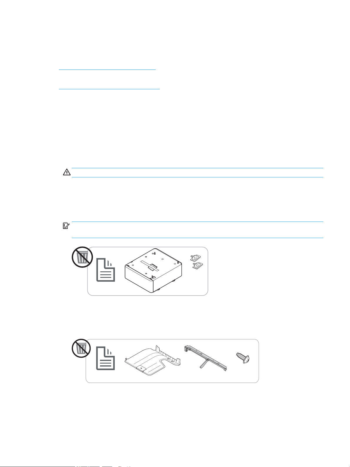
Install the model nameplate and barcode label
1. Locate the large bag containing the CD, power cord, tray labels, etc.
2. Inside the large bag , locate the smaller bag containing the three HP LaserJet model nameplates and three
“XA3” barcodes.
62 Chapter 6 Late point dierentiation conguration (LPDC) ENWW
Page 69

3. Select the appropriate ‘XA3” bar code label that accurately corresponds with the pre-determinded engine
speed listed on the conguration page.
4. Remove and then discard the barcode axed inside front cover.
5. Select the appropriate model nameplate that accurately corresponds with the pre-determined engine
speed listed on the conguration page.
6. Install the model number nameplate on the front door of the device (snaps into place).
ENWW LPDC installation steps 63
Page 70

Process notes, cautions, and miscellaneous
Support information
●
SKUs are shipped at the slowest speed.
●
LPDC: Engine speed should be set when the printer is unboxed and rst installed.
●
Engine speed conguration is provided from HP cloud service as an LPDC license.
–
The license contains values of the model name and speed that are stored on the Formatter.
–
The license is signed by HP and validated by rmware.
–
The license is locked to a specic printer via HP immutable identity and HP serial number that cannot
be changed.
–
The printer will continue to look for speed setting for 10 minutes after the device has come to a Ready
state. Each time the device is rebooted, it will look for speed until it completes a successful LPDC
process.
–
NOTE: Printer checks for USB after start up once after entering UI ready.
NOTE: Printer checks the cloud once per minute for ten minutes after the USB check.
–
HP immutable identity is tied to a private key and secured on a trusted platform module (TPM) on the
printer MSOK.
–
Printer automatically obtains license from an HP Cloud Server when rst turned on and connected to
the internet.
–
If the printer connected to internet is behind a rewall using a proxy server and port address, it will
need to be congured in EWS or the control panel prior to using the automatic cloud LPDC process.
●
After the LPD license is installed, all customer settings on the printer are set back to the factory defaults.
64 Chapter 6 Late point dierentiation conguration (LPDC) ENWW
Page 71

7 On-site nal setup
●
On-site nal setup checklist
●
Clean laser scanner assembly after setup (HP Color LaserJet MFP E87640, E87650, E87660)
●
Check the vertical gap between engine and nisher
●
Load paper trays
●
Install paper tray labels
●
Staples
●
Print and copy tests
ENWW 65
Page 72

On-site nal setup checklist
Table 7-1 On-site nal setup checklist
❑
Remove any shipping materials or brackets that were installed for shipment after the device was tested during the installation
process.
❑
Reinstall any input or output devices/nishers.
❑
Clean the laser scanner assembly window.
❑
Clean the scanner glass.
❑
Check the vertical gap between the engine and nisher, if installed.
❑
Load paper in trays.
❑
Label paper trays, if required.
❑
Load staples.
❑
Perform print and copy tests.
66 Chapter 7 On-site nal setup ENWW
Page 73

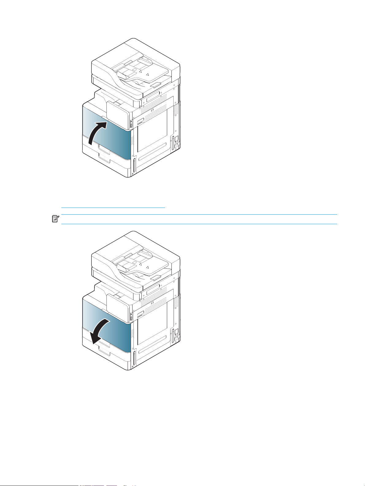
Clean laser scanner assembly after setup (HP Color LaserJet MFP E87640, E87650, E87660)
Cleaning the laser scanner assembly window (HP Color LaserJet MFP E87640, E87650, E87660 only)
1. Open the front cover and remove the toner collection unit (TCU).
Figure 7-1 Remove the TCU
2. Remove the laser scanner assembly window cleaning tool located on the front cover.
Figure 7-2 Remove laser scanner assembly window cleaning tool
ENWW Clean laser scanner assembly after setup (HP Color LaserJet MFP E87640, E87650, E87660) 67
Page 74

3. Insert the laser scanner assembly window cleaning tool into each color entrance.
Figure 7-3 Laser scanner assembly color entrances
4. Slowly remove and reinsert the cleaning tool.
5. Repeat step 4 at least four times for each laser scanner assembly window.
Cleaning the ow document feeder white bar and CIS
1. Open the ADF unit, and peel back the white backing.
CAUTION: Do not bend or fold white foam backing generating a crease in the white foam backing.
68 Chapter 7 On-site nal setup ENWW
Page 75
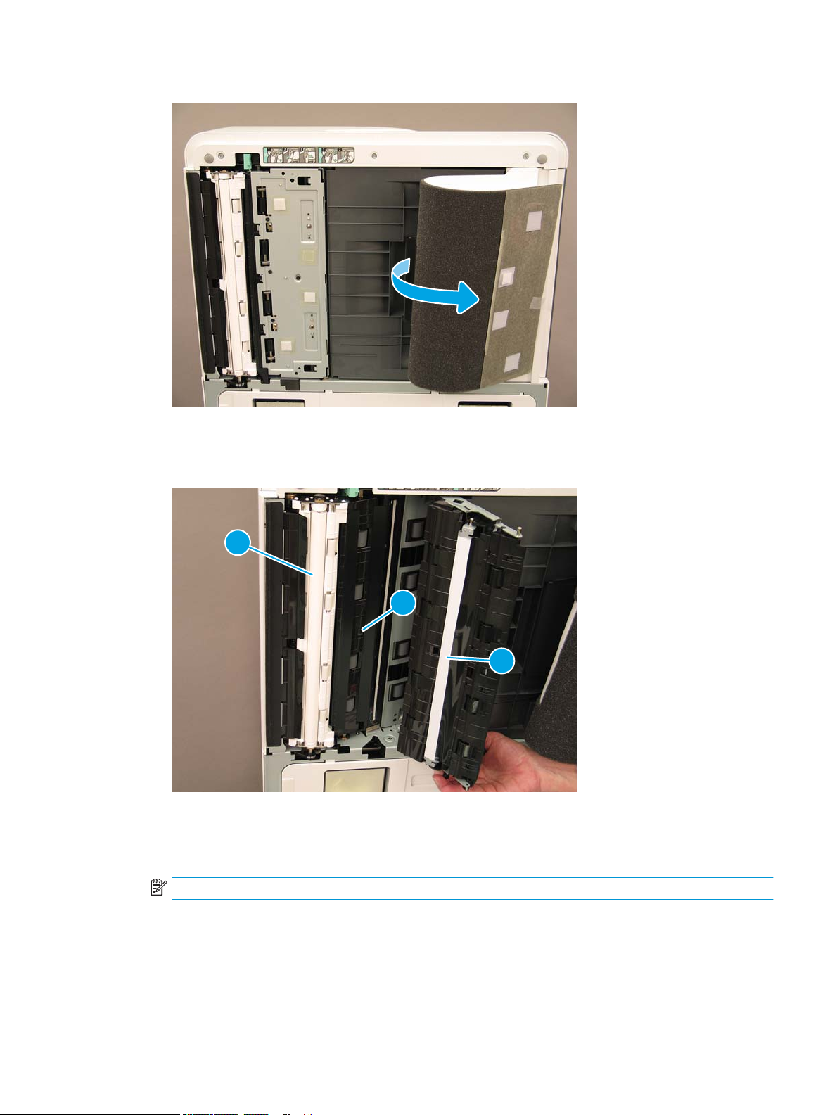
Figure 7-4 Open ADF unit
1
2
3
2. Clean the simplex white bar (callout 1), the CIS (callout 2), and the duplex white bar (callout 3) using a soft,
lint-free, clean cloth.
Figure 7-5 Clean ADF white bar
Cleaning the scan glass
▲
Open the ow document feeder unit. Clean the scanner glass (callout 1) using a soft, lint-free, clean cloth.
NOTE: Make sure to clean the main scanner glass area.
ENWW Clean laser scanner assembly after setup (HP Color LaserJet MFP E87640, E87650, E87660) 69
Page 76

Figure 7-6 Clean the scanner glass
1
Check the vertical gap between engine and nisher
Check the vertical gap between the nisher and engine. If the space is not equal at top and bottom, adjust the
casters on the nisher to make the gap even.
Load paper trays
NOTE: See the Load paper in trays and input devices in the Engine adjustments and tests in the Staging section
for detailed instructions.
Install paper tray labels
1. Locate the appropriate label size.
70 Chapter 7 On-site nal setup ENWW
Page 77

2. Locate the embossed line on the lower right of the tray and apply the label.
Staples
NOTE: See the Staples task in the Complete installation procedures section for detailed instructions.
Engine rmware upgrade after installing nisher
CAUTION: After installing any accessory the rmware must be updated to make sure the printer rmware is
compatible with the accessory.
1. Perform the rmware upgrade.
2. Verify the new nishing accessory is recognized and available.
ENWW Staples 71
Page 78

Print and copy tests
1. Print a conguration page.
2. Print a color page. (HP Color LaserJet MFP E87640, E87650, E87660 only)
3. Run at least one single and one double sided copy.
4. Run at least one scan to USB, if active. (Applies to all models.)
5. Run print output to verify the stapler stacker and/or booklet maker is functioning properly, if installed.
72 Chapter 7 On-site nal setup ENWW
Page 79

8 Complete installation procedures
●
Cabinet stand and dual cassette feeder (DCF) installation
●
2000-sheet HCI
●
Install the 3000-sheet sHCI
●
Installing tray heater in a HP LaserJet 2000-sheet HCI
●
Finishers
●
Stabilization Chocks
ENWW 73
Page 80

Cabinet stand and dual cassette feeder (DCF) installation
Install the cabinet on the HP LaserJet MFP E82540, E82550, E82560
Click here to view a video of this procedure.
Please review the LaserJet A3 videos for a complete understanding of the installation of each device. Use these
checklists as a reminder of the steps demonstrated in the videos.
CAUTION: The engine assembly is heavy and requires four people to lift.
Table 8-1 Cabinet installation
❑
Unbox the cabinet.
❑
Install three alignment pins on top of the cabinet.
❑
Locate and set aside the two thumbscrews for later.
❑
Unpack the MFP.
❑
Remove the packing foam and tape.
❑
Remove the scanner support bracket.
❑
Remove the package containing the imaging unit and set aside.
❑
Locate and install two lift assist handles on the left side of the MFP.
CAUTION: The device weighs 113.1 kg (249.3 lbs).
❑
Use four people to lift the device and carefully align on the cabinet.
❑
Remove the lift assist handles.
❑
Remove the remaining tape and packing foam from the device.
❑
Remove the foam shipping block from the MP tray (Tray 1).
❑
Remove the packing materials from the trays and then remove the trays.
❑
Install the two thumbscrews to secure the MFP to the cabinet.
❑
Reinstall the trays.
❑
Remove the protective lm from the logo on the front door.
❑
Remove the scanner lock screw and label and install the screw cover.
❑
Open the front door.
❑
Remove the seal from the toner cartridge opening.
❑
Remove the developer unit shipping support.
❑
Pull down then straight out to remove the developer unit shipping seal.
❑
Verify the seal is not torn and no pieces are left attached to the developing unit shutter.
❑
Unpack the toner cartridge and locate the two seals.
❑
Pull DOWN to remove the seal on the bottom. Pull OUT to remove the seal at the rear.
❑
Shake the toner cartridge to distribute the toner.
❑
Install the toner cartridge and while holding IN, rotate the handle to the left to lock the toner cartridge into place.
74 Chapter 8 Complete installation procedures ENWW
Page 81

Table 8-1 Cabinet installation (continued)
❑
Open the right door – this removes the interlock blocking the drum unit opening.
❑
Remove the drum from the foam packing.
❑
Cut open the black protective bag and remove the drum unit.
❑
On the orange cover, locate the arrows numbered 1, 2, 3.
❑
Pull up at each location in order to release the cover from the drum unit.
❑
Rotate the drum unit and grasp the gray handle on top.
❑
Locate and grasp the handle on the front of the drum unit.
❑
Align the slots along the top of the drum unit with the rails on the engine.
❑
Carefully insert the drum unit until it is seated, and then use the thumbscrew to secure the drum unit in the engine.
❑
Install the TCU (toner collection unit).
TIP: Push rmly on both sides at the same time to lock the TCU into the engine.
❑
Close the front door.
❑
Close the right door.
❑
Perform Late Point Dierentiation and Conguration (LPDC).
❑
Apply the “XA3” barcode inside the front door and nameplate on the outside of the front door.
❑
Upgrade rmware with the latest available on hp.com.
❑
Insert the thumb drive with rmware at the connector on the control panel.
❑
Select the following: Support Tools > Maintenance > USB Firmware Upgrade.
NOTE: All accessories must be attached when upgrading rmware.
NOTE: Accessories added later will NOT be upgraded automatically.
ENWW Cabinet stand and dual cassette feeder (DCF) installation 75
Page 82

2000-sheet HCI
Install the 2000-sheet HCI on the HP Color LaserJet MFP E87640, E87650, E87660
. Click here to view a video of this procedure.
Please review the LaserJet A3 videos for a complete understanding of the installation of each device. Use these
checklists as a reminder of the steps demonstrated in the videos.
Table 8-2 2000-sheet HCI installation
❑
Unpack the 2000-sheet HCI (high capacity input).
❑
Remove the packing foam and tape.
NOTE: The 2000-sheet HCI comes congured for A4 paper size, follow these steps to convert to letter LTR size.
❑
Locate the paper guides at the front and the rear that need to be moved.
❑
Remove one screw on top and remove the right rear guide.
NOTE: The locating slots and tabs on the top and the tabs on the bottom of guide.
NOTE: The A4/LTR slots in the bottom of the tray.
❑
Align the guide to the LTR locations at the top and on the bottom.
❑
Reinstall the screw to secure the guide.
❑
Perform the same steps for the front right guide.
❑
Remove one screw which secure the front left guide at the bottom..
NOTE: This is a plastic tapping screw. Be sure not to over-tighten when reinstalling.
❑
Remove the front left guide and not the tabs on the bottom and the corresponding LTR and A4 slots on the bottom of
the tray.
❑
Align the guide to the LTR locations at the bottom.
❑
Reinstall the screw.
TIP: When reinstalling, turn the screw CCW rst and then CW to nd the original threads.
❑
Remove one screw which secures the left rear guide at the bottom.
❑
Remove the guide and lay at in the tray.
❑
Note the A4/LTR alignment bracket on the rear of the guide.
❑
Unpack the MFP.
❑
Remove packing foam and tape.
❑
Remove the scanner support bracket.
❑
Remove the package containing the drum units and set aside.
❑
Remove one screw and rotate the bracket to the LTR orientation.
❑
Replace the self-tapping screw. Be careful to start correctly and don’t over-tighten.
NOTE: If the guides need to be adjusted AFTER the MFP is installed, access to the rear guides requires that the
2000-sheet HCI tray rails be release to allow the tray to extend out further.
❑
Locate the thumbscrews which are used to attach the MFP to the 2000-sheet HCI. Set these aside for later.
76 Chapter 8 Complete installation procedures ENWW
Page 83

Table 8-2 2000-sheet HCI installation (continued)
❑
Locate and install two lift assist handles to the left side of the MFP.
CAUTION: The device weighs 113.1 kg (249.3 lbs).
❑
Use four people to lift the device and carefully align on to the 2000-sheet HCI.
❑
Remove the lift assist handles.
❑
Remove the remaining tape and packing foam from the device.
❑
Remove the foam shipping block from the MP tray (Tray 1).
❑
Remove the packing materials from the trays and then remove the trays.
❑
Install the two thumbscrews to secure the MFP to the 2000-sheet HCI.
❑
Reinstall the trays.
❑
Remove the scanner lock screw and label and install the screw cover.
❑
Remove the protective lm from the logo on the front door.
❑
Open the front door and install the toner cartridges.
NOTE: Be sure to shake the toner cartridges vigorously (in the horizontal orientation) to loosen any compacted toner.
❑
Rotate the blue cross handle CCW until it pops o and then install the toner cartridge. Repeat for each toner cartridge.
❑
Pull straight OUT to remove the ITB cleaner seal. Verify the seal is not torn and no pieces are left attached to the ITB cleaner shutter.
❑
Pull straight OUT to remove seals on each developing unit. Verify the seals are not torn and no pieces are left attached to the
developing unit shutters.
❑
Rotate each drum unit lock lever DOWN.
❑
Remove the drums from the foam packaging.
NOTE: One drum unit is labeled K (black) and is unique for the black location.
❑
Push on each end of the orange drum cover to release it.
❑
Hold the drum unit with one hand on the bottom and one hand on the handle on the front of the drum unit.
CAUTION: Don’t use the toner waste pipe as a handle.
❑
Align the groove on the top of the drum unit to the guide at the top of the opening.
❑
Install the drum unit and then rotate the drum lock lever UP to secure the drum unit in position.
❑
Repeat these steps for the remaining drum units.
NOTE: Be sure to install the drum unit labeled “K” in the black location.
❑
Rotate each toner supply shutter CCW to open.
❑
Verify EACH lock lever is UP and each toner supply shutter is OPEN.
❑
Install the TCU by pushing rmly on both ends and close the front door.
❑
Install the duplex turnaround guide with the barcode label facing up.
TIP: Flex the guide and install the front and rear pins rst and then slide up to snap the middle pin into position on the 2nd exit.
❑
Install the paper settling guides at two locations on the rst exit.
❑
Perform Late Point Dierentiation and Conguration (LPDC).
❑
Apply the “XA3” barcode inside the front door and nameplate on the outside.
ENWW 2000-sheet HCI 77
Page 84

Table 8-2 2000-sheet HCI installation (continued)
❑
Upgrade the rmware to latest available on hp.com.
❑
Insert the thumb drive with rmware at the connector on the control panel.
NOTE: All accessories must be attached when upgrading rmware.
NOTE: Accessories added later will NOT be upgraded automatically.
78 Chapter 8 Complete installation procedures ENWW
Page 85

Install the 3000-sheet sHCI
The HCI tray is congured for size A4 by default. Use the following steps to congure the HCI tray for LTR sizes.
. Click here to view a video for this procedure.
CAUTION: The engine assembly is heavy and requires four people to lift.
Please review the LaserJet A3 videos for a complete understanding of the installation of each device. Use these
checklists as a reminder of the steps demonstrated in the videos.
Table 8-3 Cabinet installation
❑
Power down the MFP.
❑
Unpack the sHCI and attachment hardware.
❑
Remove the covers and the screws on the right lower cover on the MFP input device.
NOTE: The sHCI is not compatible with a stand.
❑
Open the lower right door slightly to allow the surrounding cover to be remove.
❑
Hang the two attachment brackets on the side of the MFP input device.
❑
Install two screws into each bracket.
❑
Locate the rail and rail support bracket.
❑
Find the tab on the rail support bracket and not how it engages on the bottom of the MFP input device.
❑
Position the rail into the support bracket.
❑
Pinch and remove the covers on the front and the rear guides.
❑
Locate the LTR positions at the top and on the bottom of each guide.
NOTE: Push the tray down to see the bottom locations.
❑
Remove the screws and move the guides to the LTR position.
❑
Reinstall the screws and covers on the front and the rear guides.
❑
Remove the short “dummy” guides from the LTR positions.
❑
Remove the tall side guides from the A4 positions and install in the LTR position.
❑
Remove the short dummy guides in the A4 position and install in the LTR positions.
NOTE: The “U” shape of the rail faces the grounding clip on the support bracket.
❑
Extend the rail until it stops in the bracket.
❑
Position the support bracket under the device and engage the tab.
❑
Install four screws to secure the bracket to the MFP.
❑
Pry from the rear to remove knock out covers at the four locations on the lower right cover.
❑
Reinstall the lower right cover.
❑
Remove the paper path opening cover just above the lower right door.
❑
Install the paper path guide. Note the three tabs are located at the TOP of the opening.
❑
Fully extend the attachment rail and position the sHCI near the end of the rail.
ENWW Install the 3000-sheet sHCI 79
Page 86

Table 8-3 Cabinet installation (continued)
❑
While holding the rail, slide the sHCI into the rail until it stops.
❑
Install the pin to secure the rail to the sHCI and secure the two screws.
❑
Connect the sHCI cable to the engine.
❑
Push the sHCI rmly toward the engine to engage the locking mechanism.
❑
Check the vertical gap between the engine and the sHCI. It should be equal from the top to the bottom.
❑
If not equal, unlatch and move the sHCI away. Adjust the leveling feet on the engine until the gap is equal.
80 Chapter 8 Complete installation procedures ENWW
Page 87

Installing tray heater in a HP LaserJet 2000-sheet HCI
Please review the LaserJet A3 videos for a complete understanding of the installation of each device. Use these
checklists as a reminder of the steps demonstrated in the videos.
NOTE: The installation of the tray heater in the 2000-sheet HCI is shown.
NOTE: These devices come standard with tray heaters in tray 2 and tray 3. Tray heaters are also available as an
accessory for the dual cassette feeder and 2000 Sheet HCI. Tray heaters are not supported in the sHCI.
Click here to view a video of this procedure.
Table 8-4 On-site installation of tray heaters
❑
Power down and unplug the MFP.
CAUTION: You MUST unplug because the tray heaters are ALWAYS energized if f the power cord is plugged in and the tray heater
switch is ON.
❑
Unpack the tray heater.
❑
Open the tray on the 2000-sheet HCI.
❑
Rotate the latch on the left.
❑
Push in on the latch on the right.
❑
Remove the tray from the 2000-sheet HCI..
❑
Note the cable connector on the tray heater.
❑
Note the tabs on the rear of the tray heater.
❑
Route the cable through the opening in the rear wall of the 2000-sheet HCI..
❑
Insert the tabs on the rear of the tray heater into the slots in the rear wall of the 2000-sheet HCI.
❑
Install one screw to secure the tray heater.
❑
Remove the rear cover of the 2000-sheet HCI.
❑
Connect the cable from the tray heater to the cable of the 2000-sheet HCI.
❑
Reinstall the rear cover of the 2000-sheet HCI..
❑
Reinstall the tray into the 2000-sheet HCI.
❑
Remove trays 2 and 3 from the main body.
❑
Locate the tray heater power switch in the rear of the tray opening.
❑
Turn the switch ON to apply power to the tray heater(s).
❑
Reinstall trays 2 and 3 into the device.
❑
Plug the MFP into the power outlet and power the device on.
ENWW Installing tray heater in a HP LaserJet 2000-sheet HCI 81
Page 88

Finishers
Install the Inner Finisher on the HP Color LaserJet MFP E87640, E87650, E87660
. Click here to view a video of this procedure.
CAUTION: The engine assembly is heavy and requires four people to lift.
Please review the LaserJet A3 videos for a complete understanding of the installation of each device. Use these
checklists as a reminder of the steps demonstrated in the videos.
Table 8-5 On-site nal setup inner nisher on the HP Color LaserJet MFP E87640, E87650, E87660
❑
Remove the duplex turn around support.
TIP: Squeeze both sides toward the middle to remove the support.
❑
Remove the two paper settling guides.
❑
Gently lift the hook and remove the bin full actuator from the rst exit.
❑
Remove two screws on the left side of the power button cover.
❑
Remove two screws at the front of the face-down bin (one screw requires a stubby JIS#2 driver).
❑
Pull OUT at the top to remove the left side of the power button cover.
NOTE: A tab on the lower edge of the cover engages with a slot on the engine.
❑
Snap o the upper left cover.
❑
Lift and pull out to remove the output bin.
❑
Reinstall the left side of the power button cover.
❑
Remove the gray cover on the back wall under the scanner by removing four screws.
NOTE: The two screws have a stick-on covers.
❑
Unpack the inner nisher and locate the second exit bin full assembly.
❑
Locate the pins on the rear and the three tabs along the length of the bin full sensor assembly.
❑
Locate the corresponding holes and the slots on the second exit assembly.
❑
Insert the tabs and slide the assembly toward the rear to t the pins into the holes.
❑
Install one self-tapping screw at the front to secure the bin full sensor assembly.
❑
Connect the bin full sensory assembly cable to the engine.
❑
Reinstall the gray cover on the back wall under the scanner by installing 4 screws and four screw covers.
❑
Locate the wavy roller retainer.
TIP: It looks like an upside down letter “U” with hooks on the ends.
❑
Push down and hold the middle roller on the rst exit assembly.
❑
Install the retainer to hold the middle roller down.
❑
Locate the slide rails.
❑
Align the slides to the locator pins located on the top of the engine.
NOTE: The white plastic end guide faces left.
82 Chapter 8 Complete installation procedures ENWW
Page 89

Table 8-5 On-site nal setup inner nisher on the HP Color LaserJet MFP E87640, E87650, E87660 (continued)
❑
Use a short stubby JIS#2 drive to install three screw in each side.
NOTE: These are self-tapping screws and require downward force to tap the holes.
CAUTION: The inner rails have sharp edges.
TIP: Slide the inner rails to the right to make the installation of the inner nisher easier.
❑
Position the inner nisher against the back wall of the opening.
❑
Hold level and then push IN to engage the unit in the slides.
❑
Open the front door and release the latch.
❑
Pull the nisher out and then back in to verify it is properly engaged with the slides.
❑
Remove stapler shipping lock label and remove shipping lock screw.
❑
Remove connector cover on the left side of MFP.
❑
Connect the inner nisher cable to the MFP.
❑
Locate the output tray.
NOTE: Four pins on the bottom of the tray need to be aligned with the holes on the support brackets.
NOTE: Push down rmly to engage the pins into the holes on the bracket.
NOTE: Lift the output nger assembly when installing the tray.
❑
Install the tray on the support brackets and push down rmly to seat the pins in the holes.
❑
Hold the tray from above while installing the self-taping screws from below.
Install the Inner Punch
Click to view a video of this procedure.
Please review the LaserJet A3 videos for a complete understanding of the installation of each device. Use these
checklists as a reminder of the steps demonstrated in the videos.
CAUTION: The engine assembly is heavy and requires four people to lift.
NOTE: The inner punch must be purchased separately and is installed in the inner nisher. This is a checklist for
installing the inner punch into a new inner nisher.
NOTE: There are three dierent hole punch accessories that can be added to the Inner nisher 2/3. 2/4 and
Swedish.
Table 8-6 On-site nal setup inner nisher punch
❑
Unpack the inner nisher and remove all the blue packing tape.
❑
Open the inner nisher front door.
❑
Unlatch and open the jam access area (also know as the dummy punch).
❑
Remove and discard the mylar surrounding the latch handle.
❑
Use a piece of blue tape to hold the latch in the open position.
❑
Locate and remove the e-clip and plastic washer just behind the lever.
ENWW Finishers 83
Page 90

Table 8-6 On-site nal setup inner nisher punch (continued)
❑
Remove the blue tape, close the dummy punch and close the front door.
❑
Place the nisher front side down on a table.
❑
Locate and remove three screws on the rear cover.
❑
Use a at blade screwdriver to release the cover tab located at the lower rear corner near the cable entrance and lift the cover
slightly.
❑
Now pull along the top edge to release three tabs and remove the cover.
❑
Locate the hinge pin at the rear of the dummy punch.
❑
Remove the e-clip at the bottom of the hinge pin and remove the hinge pin.
❑
Disconnect the cable.
❑
Turn the nisher back to its normal orientation..
❑
Open the front cover.
❑
Open the dummy punch.
❑
Pull forward to remove the dummy punch from the inner nisher.
❑
Unpack the inner punch.
❑
Position the inner punch on the inner nisher and slide the cables through the chassis at the rear.
❑
Close the inner punch and the front cover.
❑
Place the inner nisher front side down on a table.
❑
Insert the hinge pin – verify cables are located to the left of the pin.
❑
Replace the e-clip.
❑
Connect the two cables.
❑
Replace the rear cover.
TIP: Locate the three tabs along the top of the cover and engage with corresponding holes on the frame.
❑
Snap the cover back down in the lower corner.
❑
Reinstall three screws.
❑
Turn the nisher back to its normal orientation.
❑
Open the inner nisher front door.
❑
Unlatch and open the inner punch.
❑
Use a piece of blue tape to hold the latch in the open position.
❑
Place the black washer on the pin.
❑
Reinstall the e-clip on the pin.
❑
Peel o the backing and install the new mylar over the opening.
❑
Remove the dummy door and install the punch waste bin.
❑
Remove the blue tape and close the inner nisher.
84 Chapter 8 Complete installation procedures ENWW
Page 91

Stapler/Stacker Finisher
Click here to view a video of this procedure.
Please review the LaserJet A3 videos for a complete understanding of the installation of each device. Use these
checklists as a reminder of the steps demonstrated in the videos.
NOTE: There are three dierent hole punch accessories that can be added to the Stapler/Stacker nisher 2/3.
2/4 and Swedish.
Stapler/Stacker Finisher
Table 8-7 On-site nal setup stapler/stacker
❑
Power down the MFP.
❑
Unpack nisher, bridge and attachment hardware.
NOTE: On the engine, remove the bin full actuator, paper settling arms and face down bin.
❑
Install the bridge (IPTU) on the engine. Secure with one screw. Click here to view a video of this procedure.
❑
Remove the packing foam and tape from the nisher.
❑
Open the top cover on nisher and remove the foam and tape inside the paper path.
❑
Open front door on nisher and remove packing foam and tape inside door..
❑
Remove the stapler shipping lock screw and label.
❑
Rotate the green wheel to the left until the spring loaded white tab is exposed under the stapler.
❑
Rotate the green wheel to the right until the stapler moves back to the front position and stops.
❑
While holding the green wheel, insert the staple cartridge holder into the stapler.
❑
Hang the lower tray support brackets on the horizontal bracket on the output side of the nisher.
❑
Secure each bracket with one screw.
❑
Note the alignment pins on the bottom of the tray and the corresponding holes on the support brackets.
❑
Position the tray over the brackets and push down rmly to seat the pins in the holes.
❑
While holding the tray from above, install four screws to secure the tray to the support brackets.
❑
Note the four tabs. Install the upper tray into the slots.
❑
Install front (F) and the rear (R) and the nisher attachment brackets on the left side of the engine.
❑
Secure with two screw in each bracket.
❑
Peel the cover o the connector near the rear bracket.
❑
Position the nisher near the left side of the engine and connect the two cables.
❑
Open the nisher front door and pull out the locking rail until it stops.
ENWW Finishers 85
Page 92

Table 8-7 On-site nal setup stapler/stacker (continued)
❑
Align the brackets on the engine to the holes on the nisher and roll the nisher against the engine.
❑
Push the locking rail in and install one screw to secure the nisher to the engine.
NOTE: If the locking rail won’t slide in easily, adjust the casters on the nisher to change the height.
NOTE: Check the vertical gap between the nisher and the engine. Adjust the casters for an equal gap from top to bottom.
NOTE: Remove the nisher from the engine if the MFP needs to be moved anything more than a very short distance.
Booklet Maker Finisher with punch
Click here to view a video of this procedure.
Please review the LaserJet A3 videos for a complete understanding of the installation of each device. Use these
checklists as a reminder of the steps demonstrated in the videos.
NOTE: There are three dierent hole punch accessories that can be added to the Booklet Maker nisher 2/3.
2/4 and Swedish.
.
Table 8-8 On-site nal setup booklet maker nisher with punch
❑
Power down the MFP.
❑
Unpack nisher, bridge and attachment hardware.
NOTE: On the engine, remove the bin full actuator, paper settling arms and face down bin.
❑
Install the bridge (IPTU) on the engine. Secure with one screw. Click here to view a video of this procedure.
❑
Remove packing foam and tape from the nisher.
❑
Open the top cover and remove the foam and tape inside the paper path.
❑
Locate and remove the shipping bracket for the booklet maker. Use one screw to store the bracket on the frame.
❑
Open the front door on the nisher and remove all foam and tape inside the nisher.
❑
Pull out the booklet maker and install two staple cartridge holders in the top of the booklet maker.
❑
Slide the booklet maker into the nisher.
❑
Remove the stapler lock screw and label.
❑
Rotate the green wheel to the left until the spring loaded white tab is exposed under the stapler.
❑
Rotate the green wheel to the right until the stapler moves back to the front position and stops.
❑
While holding the green wheel, insert the staple cartridge holder into the stapler.
❑
Follow these steps to install the optional hole punch.
❑
Remove two screws and remove the punch unit access panel on the rear of the nisher.
❑
Remove two screws and remove the “dummy” punch unit.
NOTE: Save the dummy punch in the event the hole punch fails; it’s needed if the hole punch is removed.
❑
Locate the alignment pin and tab at the front of the punch unit and the mounting bracket at the rear.
NOTE: Be careful when handling the punch unit. Do not damage the mylar guides or the encoder wheel.
86 Chapter 8 Complete installation procedures ENWW
Page 93

Table 8-8 On-site nal setup booklet maker nisher with punch (continued)
❑
Carefully slide the punch unit into the nisher. Align the mounting bracket at the rear.
NOTE: The punch unit is properly seated when the mounting bracket at the rear is ush against the nisher frame.
NOTE: The orientation of the pins on the connector. While supporting the connector on the nisher side, insert the hole
punch cable connector.
❑
Install one screw to secure the punch unit in the nisher.
❑
Replace the punch unit access panel and secure with two screws.
❑
Open the front door of the nisher and install the punch waste bin label.
❑
Pry the cover out of the punch waste bin opening and install the punch waste bin.
❑
Hang the lower tray support brackets on the horizontal bracket on the output side of the nisher.
❑
Secure each one with a screw.
❑
Note the alignment pins on the bottom of the tray and the corresponding holes on the support brackets.
❑
Position the tray over the brackets and push down rmly to seat the pins in the holes.
❑
While holding the tray from above, install four screws to secure the tray to the support brackets.
❑
Note the four tabs, install the upper tray into the slots.
❑
Install the front (F) and the rear (R) nisher attachment brackets on the left side of the engine.
❑
Secure with two screws in each bracket.
❑
Peel the cover o the connector near the rear bracket.
❑
Position the nisher near the left side of the engine and connect the two cables.
❑
Open the nisher front door and pull out the locking rail until it stops.
❑
Align the brackets on the engine to the holes on the nisher and roll the nisher against the engine.
❑
Push the locking rail in and install one screw to secure the nisher to the engine.
NOTE: If the locking rail won’t slide in easily, adjust the casters on the nisher to change the height.
NOTE: Check the vertical gap between the nisher and the engine. Adjust the casters for an equal gap from top to bottom.
NOTE: Remove the nisher from the engine if the MFP needs to be moved anything more than a very short distance.
Installation of HP LaserJet job separator
NOTE: There is no video available to show the procedure of how to install the job separator.
CAUTION: The engine assembly is heavy and requires four people to lift.
Use this checklist to perform the installation of the job separator.
8-9 On-site nal setup job separator
Table
❑
Remove the duplex turn around support.
TIP: Squeeze on both sides toward the middle to remove the support.
❑
Remove two screws on the left side of the power button cover.
❑
Remove two screws at the front of the face-down bin (output bin) (one screw will require a stubby JIS#2 dirver).
ENWW Finishers 87
Page 94

Table 8-9 On-site nal setup job separator (continued)
❑
Pull OUT at the top to remove the left side of the power button cover.
NOTE: A tab on the lower edge of the cover engages with a slot on the device.
❑
Snap o the upper left cover.
❑
Lift and pull out to remove the face-down bin (output bin).
❑
Remove the gray cover on the back wall under the scanner by removing four screws.
NOTE: Two screws have stick-on covers.
❑
Unpack the Job Separator and locate the 2nd exit bin full assembly.
❑
Locate the pins on the rear and the three tabs along the length of the bin full sensor assembly.
❑
Locate the corresponding holes and slots on the 2nd exit assembly.
❑
Insert the tabs and slide the assembly toward the rear to t the pins into the holes.
❑
Install one self-tapping screw at the front to secure the bin full sensor assembly.
❑
Connect the bin full sensor assembly cable to the device.
❑
Reinstall the gray cover, 4 screws and screw covers.
❑
Reinstall the left side of the power button cover.
❑
Reinstall the top output bin.
❑
Reinstall the upper left cover.
❑
Install the Job Separator by aligning the right edge to the 2nd exit area and the rear tab to the opening under the scanner.
❑
Install one screw to secure the Job Separator.
Staples
Click here to view a video of this procedure
HP LaserJet Inner nisher and Booklet Maker nisher rell staple cartridge product number: Y1G13A.
Replace the inner nisher staple cartridge
1. Open the staple cartridge access door.
88 Chapter 8 Complete installation procedures ENWW
Page 95

2. Rotate the staple cartridge handle down, and then remove the staple cartridge.
3. Lift two tabs on the staple cartridge, and then lift up to remove the empty staple cartridge from the staple
cartridge carriage assembly.
IMPORTANT: Do not discard the empty staple cartridge carriage. It must be reused with the new staple
cartridge assembly.
Reinstallation tip:
●
Add recycle and unpack step for video purposes here
●
Insert the new staple cartridge in to the staple cartridge carriage.
●
Install the staple cartridge carriage assembly.
NOTE: In order to replace staple cartridge, to remove the staple cartridge from the inner nisher the
staple cartridge must be empty.
ENWW Finishers 89
Page 96

4.
5. Close the staple cartridge access door.
Replace the staple cartridges in the booklet maker area
Click here to view a video of the following procedure.
HP LaserJet Inner nisher and Booklet Maker nisher rell staple cartridge product number: Y1G13A.
HP LaserJet Stapler/Stacker rell staple cartridge product number: Y1G14A
1. Open the booklet maker door.
90 Chapter 8 Complete installation procedures ENWW
Page 97

2. Pull out the booklet maker assembly until it stops.
3. Pull the tab down, and then remove the staple cartridge.
ENWW Finishers 91
Page 98
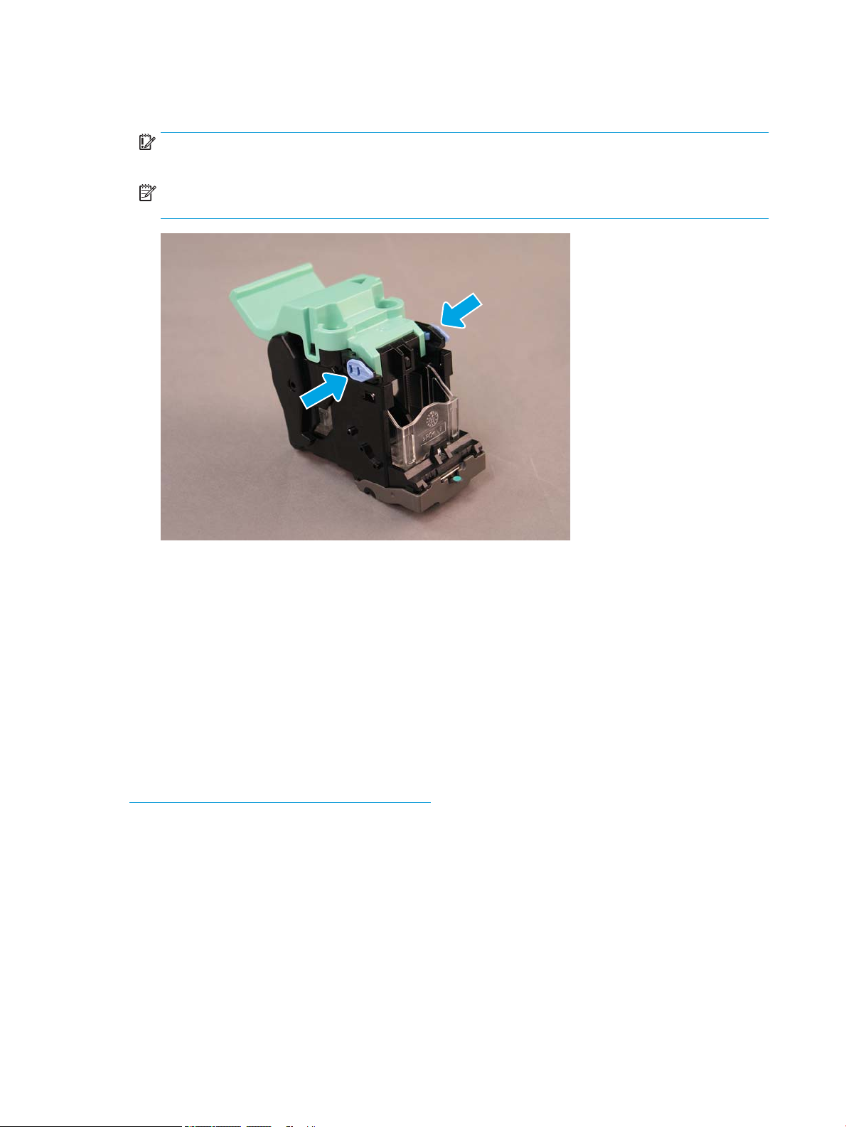
4. Pinch the blue tabs, and then rotate the top of the staple cartridge carriage assembly away from the staple
cartridge.
IMPORTANT: Do not discard the empty staple cartridge carriage. It must be reused with the new staple
cartridge assembly.
NOTE: In order to replace staple cartridge, to remove the staple cartridge from the inner nisher the
staple cartridge must be empty.
5. Lift two tabs on the staple cartridge, and then lift up to remove the empty staple cartridge from the staple
cartridge carriage assembly.
6. Insert the new staple cartridge in to the staple cartridge carriage assembly.
7. Rotate the top of the staple cartridge carriage assembly until it clicks into place.
8. Reinstall the staple cartridge carriage assembly into the booklet maker.
9. Slide the booklet maker assembly into the nisher assembly.
10. Close the booklet maker door.
Replace the staple cartridge in the stapler stacker area
Click here to view a video for the following procedure.
HP LaserJet Stapler/Stacker nisher rell staple cartridge product number: Y1G14A.
HP LaserJet Stapler/Stacker Finisher rell staple cartridge: Y1G14A.
1. Open the booklet maker door.
92 Chapter 8 Complete installation procedures ENWW
Page 99

2. Rotate the knob counterclockwise to move the staple cartridge assembly all the way to the front.
ENWW Finishers 93
Page 100

3. Hold the knob to immobilize the staple cartridge assembly, and then pull the tab down to remove the
staple cartridge.
4. Lift two tabs on the staple cartridge, and then lift up to remove the empty staple cartridge from the staple
cartridge carriage assembly.
IMPORTANT: Do not discard the empty staple cartridge carriage. It must be reused with the new staple
cartridge assembly.
NOTE: In order to replace staple cartridge, to remove the staple cartridge from the inner nisher the
staple cartridge must be empty.
94 Chapter 8 Complete installation procedures ENWW
 Loading...