

Page 1

HP 8200 zl Switches
Installation and Getting Started Guide
Power over Ethernet
Page 2

Page 3

HP 8200 zl Switches
Installation and Getting Started Guide
Page 4
© Copyright 2011, 2013 Hewlett-Packard Development Company,
L.P.
Publication Number
5998-2999
June 2013
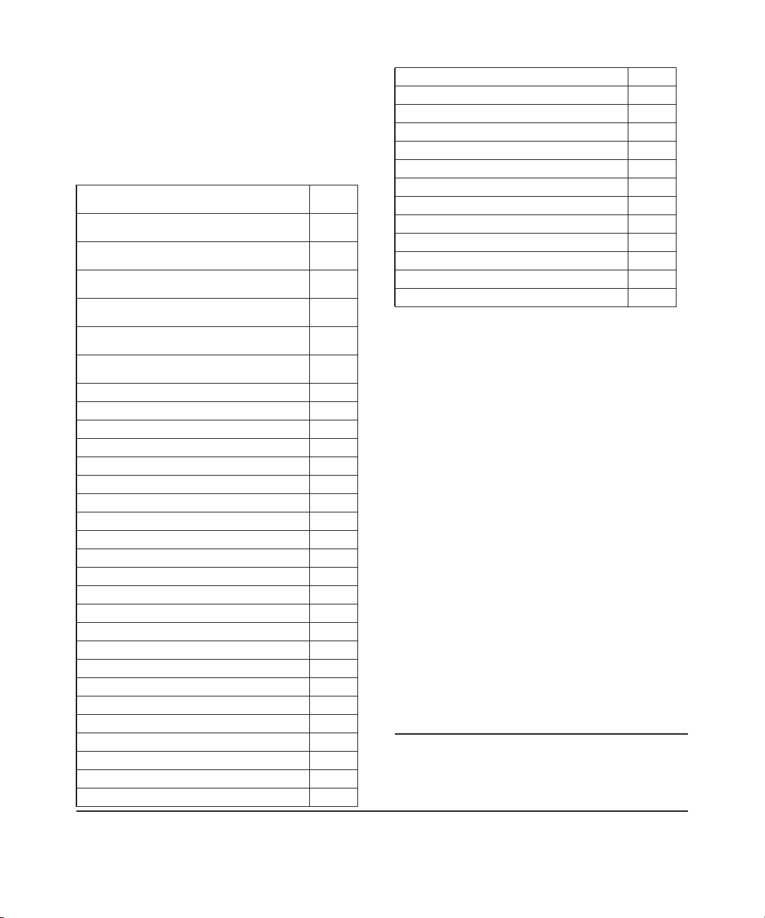
Applicable Products
HP Switch 8212 zl
(Base System)
HP Switch 8212 zl
(Replacement Chassis with Fan Tray Only)
HP Switch 8206 zl
(Base System)
HP Switch 8212 zl Fan Tray
(Replacement Fan Tray Only)
HP Switch 8206 zl Fan Tray
(Replacement Fan Tray Only)
HP 8206-44G-PoE+/2XG-SFP+ v2 zl Switch with Premium
Software
HP 8212-92G-PoE+/2XG-SFP+ v2 zl Switch with Premium
Software
HP 8206 v2 zl Switch with Premium Software J9640A
HP 8212 v2 zl Switch with Premium Software J9641A
Switch zl Power Supply Shelf J8714A
Switch zl Power Supply Shelf Rack Mounting Kit 5070-3028
Two-Post Rack Mounting Kit for Switch 8212 zl 5070-2983
8200 zl/5400 zl 10K Rack Rail Kit Assembly 5070-0145
HP ProCurve 1500W PoE+ zl Power Supply J9306A
HP ProCurve 875W PoE zl Power Supply J8712A
HP ProCurve 1500W PoE zl Power Supply J8713A
HP ProCurve 8200 zl Management Module J9092A
HP ProCurve 8200 zl System Support Module J9095A
HP ProCurve 8200 zl Fabric Module J9093A
Compact Flash Kit for 8200 zl Management Module 5070-3051
24-port Gig-T zl Module J8702A
20-port Gig-T/SFP zl Module J8705A
24-port mini-GBIC zl Module J8706A
4-port 10Gig-X2 zl Module J8707A
4-port 10Gig-CX4 zl Module J8708A
24-Port 10/100/1000 PoE+ zl Module J9307A
20-Port 10/100/1000 PoE+/4-Port MiniGBIC zl Module J9308A
4-Port 10GbE SFP+ zl Module J9309A
24-Port 10/100 PoE+ zl Module J9478A
Wireless Edge Services zl Module J9051A
J8715A/B
J9091A/B
J9475A
J9094A
J9476A
J9638A
J9639A
Redundant Wireless Services zl Module J9052A
ONE Services zl Module J9154A
HP 24-port Gig-T PoE+ v2 zl Module J9534A
HP 20-port Gig-T PoE+ / 4-port SFP v2 zl Module J9535A
HP 20-port Gig-T PoE+ / 2-port 10-GbE SFP+ v2 zl Module J9536A
HP 24-port SFP v2 zl Module J9537A
HP 8-port 10-GbE SFP+ v2 zl Module J9538A
HP 8-port 10GBase-T v2 zl Module J9546A
HP 24-port 10/100 PoE+ v2 zl Module J9547A
HP 20-port Gig-T / 2-port 10-GbE SFP+ v2 zl Module J9548A
HP 20-port Gig-T / 4-port SFP v2 zl Module J9549A
HP 24-port Gig-T v2 zl Module J9550A
HP 12-port Gig-T / 12-port SFP v2 zl Module J9637A
Disclaimer
HEWLETT-PACKARD COMPANY MAKES NO WARRANTY
OF ANY KIND WITH REGARD TO THIS MATERIAL,
INCLUDING, BUT NOT LIMITED TO, THE IMPLIED
WARRANTIES OF MERCHANTABILITY AND FITNESS
FOR A PARTICULAR PURPOSE. Hewlett-Packard shall not
be liable for errors contained herein or for incidental or
consequential damages in connection with the furnishing,
performance, or use of this material.
The information contained herein is subject to change
without notice. The only warranties for HP products and
services are set forth in the express warranty statements
accompanying such products and services. Nothing herein
should be construed as constituting an additional warranty.
HP shall not be liable for technical or editorial errors or
omissions contained herein.
Hewlett-Packard assumes no responsibility for the use or
reliability of its software on equipment that is not furnished
by Hewlett-Packard.
Warranty
For HP warranty information, visit
www.hp.com/networking/support
A copy of the specific warranty terms applicable to your
Hewlett-Packard products and replacement parts can be
obtained from your HP Sales and Service Office or
authorized dealer.
Safety
Before installing and operating these products, please read
the “Installation Precautions” in chapter 2, and “Safety and
Hewlett-Packard Company
8000 Foothills Boulevard, m/s 5551
Roseville, California 95747-5551
http://www.hp.com/networking
Page 5

Regulatory Statements” in Appendix C.
iii
Page 6

Contents
1 Introducing the HP 8200 zl Switches
Overview of the 8200 zl Switches ..................................1-2
8206 zl Switches .............................................1-2
8212 zl Switch ..............................................1-3
Network Connectivity, Speeds and Technologies ....................1-4
Front of the 8200 zl Switches ..................................... 1-5
Front of 8212 zl Switch, Base System ...........................1-5
Front of 8206 zl Switch, Base System ...........................1-6
Switch and Module LEDs .....................................1-7
LED Mode Select Button and Indicator LEDs ............... 1-12
Console Port ...........................................1-13
Reset Buttons ..........................................1-13
Module Reset ..........................................1-13
System Reset ...........................................1-13
Clear Button ...........................................1-14
Back of the 8200 zl Switches ..................................... 1-15
Back of the 8212 zl Switch ...................................1-15
Back of the 8206 zl Switch ...................................1-16
Power Supply ..............................................1-16
Switch Accessories ............................................. 1-17
Switch Features ...............................................1-19
2 Installing the HP 8200 zl Switches
Included Parts .................................................. 2-1
Power Cords ................................................... 2-2
Installation Procedures .......................................... 2-3
Summary ................................................... 2-3
Installation Precautions ...................................... 2-5
iii
Page 7

1. Prepare the Installation Site ................................ 2-7
Cabling Infrastructure ....................................2-7
Installation Location ..................................... 2-7
2. Mount the Switch Chassis ..................................2-7
Rack or Cabinet Mounting ................................2-7
Horizontal Surface Mounting .............................2-10
3. Install the Switch Modules ................................. 2-11
Installing a Management Module Battery ...................2-13
4. Install the Power Supplies .................................2-14
5. Verify the Switch Passes Self Test ..........................2-17
LED Behavior: .........................................2-19
6. Install the Grounding Wire ................................. 2-20
7. Connect the Switch to a Power Source ......................2-21
8. (Optional) Connect a Power Supply Shelf
to the switch .............................................2-21
EPS Operation .........................................2-22
Operating Characteristics of the EPS (J8714A) .............. 2-22
Power Supply Shelf LEDs ................................ 2-22
Connecting the Power Supply Shelf ....................... 2-24
9. Connect the Network Devices .............................. 2-25
10. (Optional) Connect a Console to the Switch ................. 2-27
Terminal Configuration .................................. 2-27
Direct Console Access ...................................2-28
Console Cable Pinouts ..................................2-29
Telnet Console Access ..................................2-30
Hot Swapping Switch Modules ...................................2-30
Adding or Replacing Modules ................................2-30
Changing the Module Type ..................................2-31
Example Network Topologies ...................................2-32
Basic Connectivity .........................................2-32
Use as an Edge Switch ......................................2-33
Optimizing the 10-GbE Port Configuration
with standard zl modules ...................................2-34
Optimizing the 10-GbE Port Configuration
with version 2 zl modules ................................... 2-35
iv
Page 8

3 Getting Started With Switch Configuration
Recommended Minimal Configuration ..........................3-1
Using the Switch Setup Screen ................................3-2
Where to Go From Here ...................................... 3-4
To Recover from a Lost Manager Password: ................. 3-4
Using the IP Address for Remote Switch Management ................3-5
Starting a Telnet Session .....................................3-5
Starting a Web Browser Session ............................... 3-5
Configuring the ProCurve Wireless Edge Services zl Module (J9051A) . . 3-7
Configuring an IP Address for the Module .......................3-7
Configuring VLANs on the zl Switch ............................3-9
Determining a Module Configuration Backup Process ............3-9
Configuring Wireless LAN Services ........................... 3-10
4 Replacing Components
Replacing Power Supplies ........................................ 4-2
Replacing Fan Trays .............................................4-5
Replacing the Management Module ................................4-6
Replacing the Management Module Compact Flash Card .............4-8
Installing a Compact Flash Card ............................... 4-8
Replacing the Services Module Compact Flash Card .................4-9
Installing a Compact Flash Card ............................... 4-9
Replacing the Services Module Disk Drive ......................... 4-10
Installing a Disk Drive ......................................4-10
5 Troubleshooting
Basic Troubleshooting Tips ......................................5-1
Diagnosing with the LEDs ........................................5-4
Proactive networking ............................................5-9
Hardware Diagnostic Tests ......................................5-10
Reasons for Resetting the Switch ............................. 5-10
v
Page 9

Methods of Resetting the Switch ..............................5-10
Testing the Switch by Resetting It ............................5-11
Checking the Switch LEDs ...............................5-11
Checking Console Messages ..............................5-11
Testing Twisted-Pair Cabling .................................5-12
Testing Switch-to-Device Network Communications ............5-12
Testing End-to-End Network Communications ................. 5-12
Restoring the Factory Default Configuration .......................5-13
Downloading New Code ........................................5-14
HP Customer Support Services .................................. 5-14
Before Calling Support ...................................... 5-14
A Specifications
Physical ................................................... A-1
Electrical ................................................. A-1
Environmental ............................................. A-2
Acoustic .................................................. A-2
8212 zl Switch .......................................... A-2
8206 zl Switch .......................................... A-2
Safety .................................................... A-3
EMC compliance (Class A) .................................. A-3
Technology Standards and Safety Compliance .................. A-3
B Switch Ports and Network Cables
Cabling and Technology Information Specifications ................ B-1
Technology Distance Specifications ........................... B-3
Mode Conditioning Patch Cord .................................. B-5
Installing the Patch Cord .................................... B-6
Twisted-Pair Cable/Connector Pin-Outs ........................... B-7
Straight-Through Twisted-Pair Cable for
10 Mbps or 100 Mbps Network Connections .................... B-8
Cable Diagram ......................................... B-9
Pin Assignments ........................................ B-9
vi
Page 10

Crossover Twisted-Pair Cable for
10 Mbps or 100 Mbps Network Connection .................... B-10
Cable Diagram ........................................ B-10
Pin Assignments ....................................... B-10
Straight-Through Twisted-Pair Cable for
1000 Mbps Network Connections ............................ B-11
Cable Diagram ........................................ B-11
Pin Assignments ....................................... B-11
C Safety and Regulatory Statements
Safety Information ............................................. C-1
Informations concernant la sécurité .............................. C-2
Hinweise zur Sicherheit ......................................... C-3
Considerazioni sulla sicurezza ................................... C-4
Consideraciones sobre seguridad ................................ C-5
Informações de Segurança ...................................... C-6
Safety Information (Japan) ...................................... C-7
Safety Information (China) ...................................... C-8
EMC Regulatory Statements ..................................... C-9
U.S.A. .................................................... C-9
Canada ................................................... C-9
Australia/New Zealand ...................................... C-9
Japan .................................................... C-10
Korea .................................................... C-10
Taiwan .................................................. C-10
Regulatory Model Identification Number ..................... C-10
European Community ...................................... C-11
D Recycle Statements
Waste Electrical and Electronic Equipment (WEEE) Statements ...... D-1
Index
vii
Page 11

Page 12

Introducing the HP 8200 zl Switches
The HP 8200 zl switches are high-performance, high availability switch platforms that enable unified core-to-edge adaptive network solutions and deliver
to market the industry’s first core switch with a lifetime warranty. They have
platform and software high-availability features to ensure system continuity
and enhanced network productivity.
This chapter describes your 8200 zl switches, including:
■ Overview of 8200 zl Base Switches, page 1-2
■ Network Connectivity, Speeds and Technologies, page 1-4
■ Front of the 8200 zl Switches, page 1-5
■ Back of the 8200 zl Switches, page 1-15
■ Switch Accessories, page 1-17
■ Switch Features, page 1-19
1
Introducing the HP 8200 zl
Switches
1-1
Page 13
Introducing the HP 8200 zl Switches
Overview of the 8200 zl Switches
Switches
Introducing the HP 8200 zl
Overview of the 8200 zl Switches
8206 zl Switches
1. The HP 8206-44G-PoE+/2XG-SFP+ v2 zl Switch with Premium Software
(J9638A) ships with the 8206 zl, 6-slot chassis and the following:
• One HP 24-port Gig-T PoE+ v2 zl Module (J9534A)
• One HP 20-port Gig-T PoE+ / 2-port 10-GbE SFP+ v2 zl Module
(J9536A)
• One 1500W PoE+ zl Power Supply (J9306A)
• With premium software activated
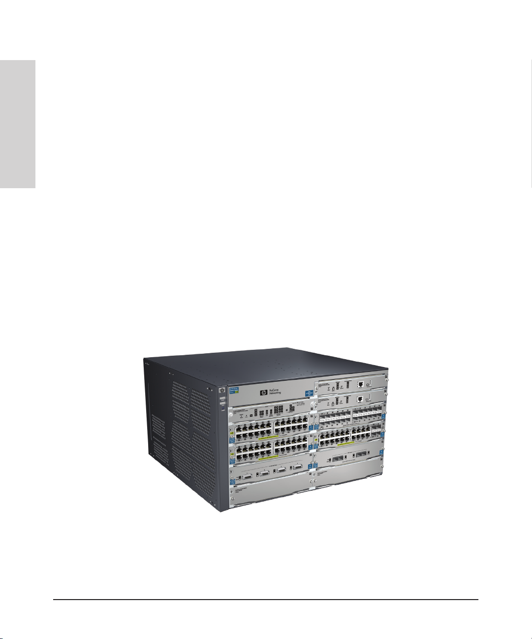
2. The HP 8206 v2 zl Switch with Premium Software (J9640A) ships with the
8206 zl, 6-slot chassis (J9475A) and the following:
• With premium software activated
• One management module
• One system support module
• Two fabric modules
• A pre-installed fan tray
1-2
Figure 1-1. HP 8206 zl Switch (J9475A shown with optional modules)
Page 14
Introducing the HP 8200 zl Switches
Overview of the 8200 zl Switches
8212 zl Switch
Note The previously available 8212 zl base system (J8715A) shipped with Intelligent
Edge and Advanced Routing features standard. Going forward, customers
requiring an 8212 zl with Advanced Routing features should order the J9641A
8212 v2 zl Switch with Premium Software.
1. The HP 8212-92G-PoE+/2XG-SFP+ v2 zl Switch with Premium Software
(J9639A) ships with the 8212 zl, 12-slot chassis and the following:
• Three HP 24-port Gig-T PoE+ v2 zl Module (J9534A)
• One HP 20-port Gig-T PoE+ / 2-port 10-GbE SFP+ v2 zl Module
(J9536A)
• One 1500W PoE+ zl Power Supply (J9306A)
• With premium software activated
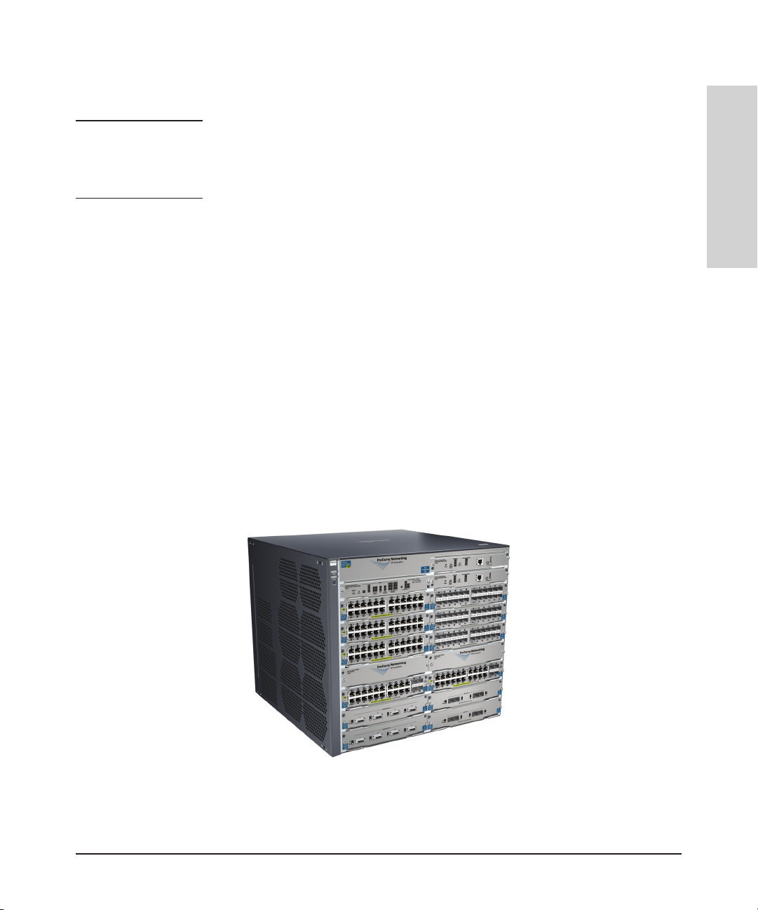
2. The HP 8212 v2 zl Switch with Premium Software (J9641A) ships with the
8212 zl, 12-slot chassis (J8715A/B) and the following:
• With premium software activated
• One management module
• One system support module
• Two fabric modules
• A pre-installed fan tray
• Intelligent Edge features and IP Base Routing features standard
Introducing the HP 8200 zl
Switches
Figure 1-2. HP 8212 zl Switch (J8715A/B shown with optional modules)
1-3
Page 15
Introducing the HP 8200 zl Switches
Network Connectivity, Speeds and Technologies
Switches
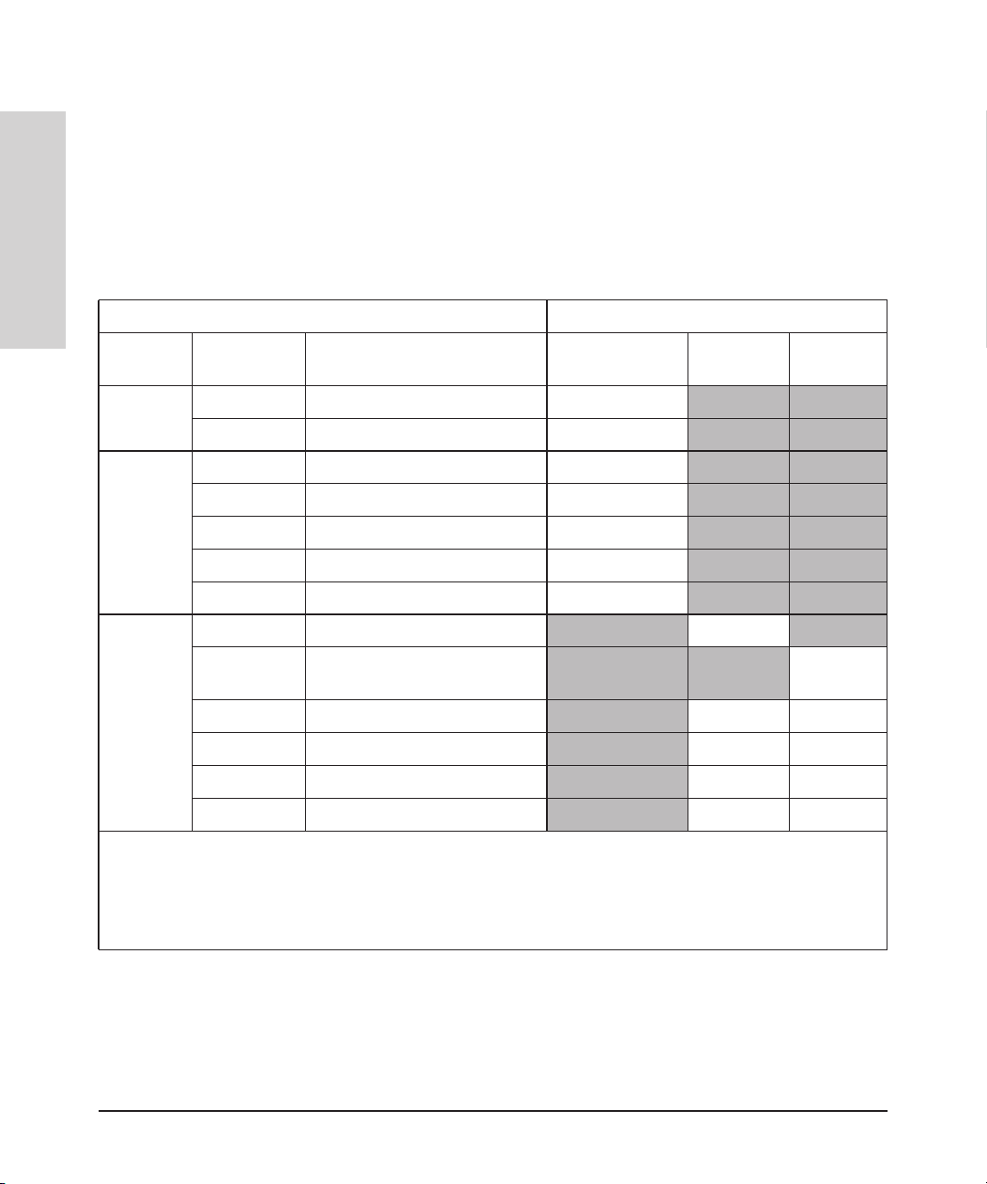
Table 1-1. Optional Network Connectivity, Speeds and Technologies
Introducing the HP 8200 zl
Speed Technology
Network Connectivity, Speeds and
Technologies
These products support optional network connectivity as follows:
Transceiver Form-Factor and Connector
Cabling
SFP ("mini-GBIC")
Connector
X2
Connector
1
SFP+
Connector
100 Mbps
1 Gbps
10 Gbps
1
For supported transceivers, visit www.hp.com/networking/support.
– In the first textbox, type J4858 (for 100-Mb and Gigabit information), or J8436 (for 10-Gigabit information).
– Select any of the products that display in the dropdown list. Click Display selected.
– Select Product support information. Then click on Manuals and find the T
For technical details of cabling and technologies see "Cabling and Technology Information" in the appendices.
100-FX Fiber (multimode) LC
100-BX Fiber (single mode) LC
1000-T Copper (twisted-pair) RJ-45
1000-SX Fiber (multimode) LC
1000-LX Fiber (multimode or single mode) LC
1000-LH Fiber (single mode) LC
1000-BX Fiber (single mode) LC
10-Gig CX4 Copper (twinaxial) CX4
10-Gig
Direct Attach
10-Gig SR
10-Gig LRM Fiber (multimode) SC
10-Gig LR Fiber (single mode) SC LC
10-Gig ER
Copper (twinaxial) Not
Applicable
Fiber (multimode) SC
Fiber (single mode) SC LC
ransceiver Support Matrix.
LC
LC
1-4
Page 16
Power
and Fault
LEDs
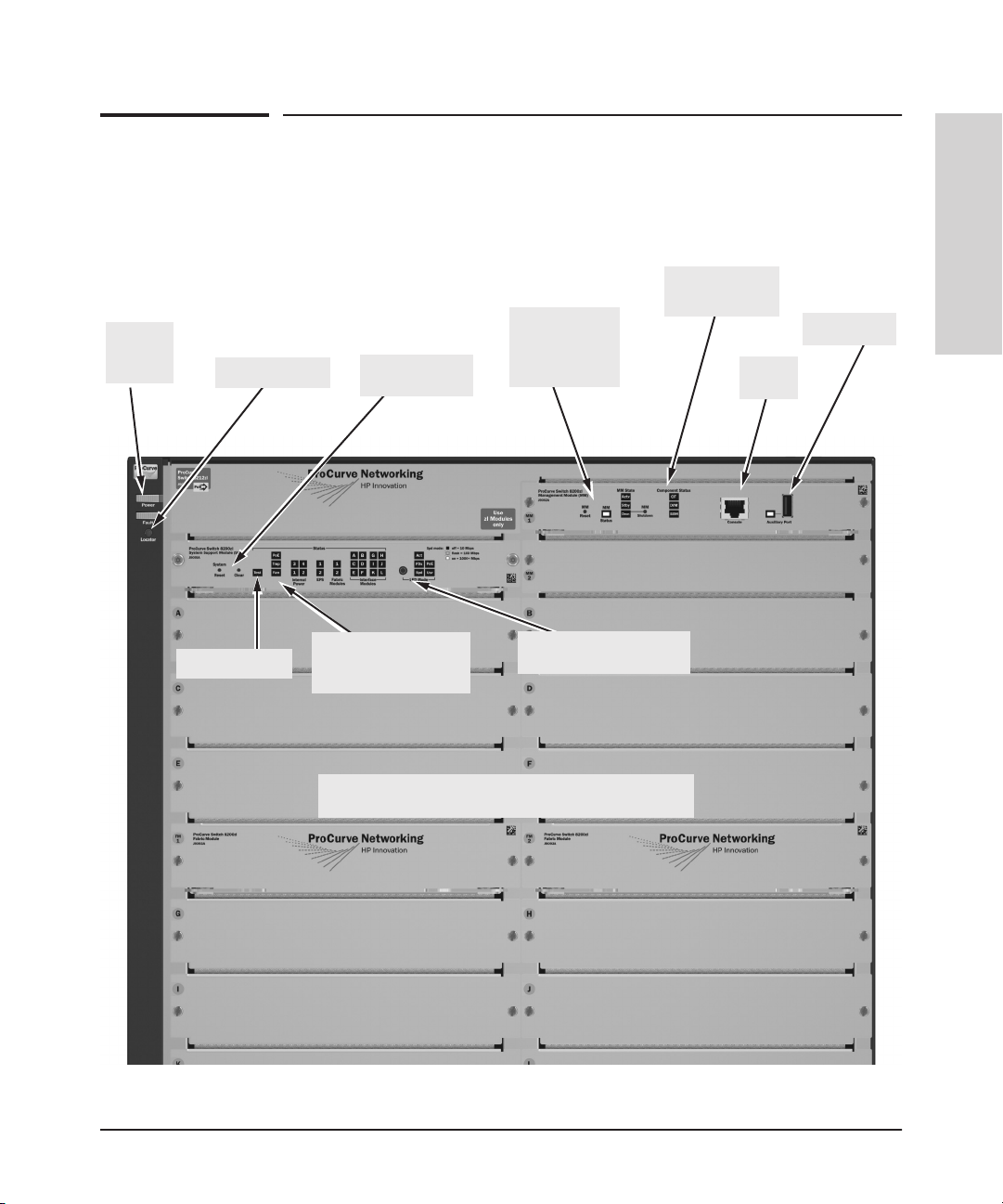
Front of the 8200 zl Switches
Front of 8212 zl Switch, Base System
Management
Module Reset
Locator LED
Reset and Clear
buttons
button, and
StatusLEDs
Introducing the HP 8200 zl Switches
Front of the 8200 zl Switches
Introducing the HP 8200 zl
Switches
Component
Status LEDs
Auxiliary Port
Console
Port
Self Test LED
Status LEDs for the
Fans, Power Supplies,
and Switch Modules
Switch Modules and slots
with Link and Mode LEDs for each port located on each module
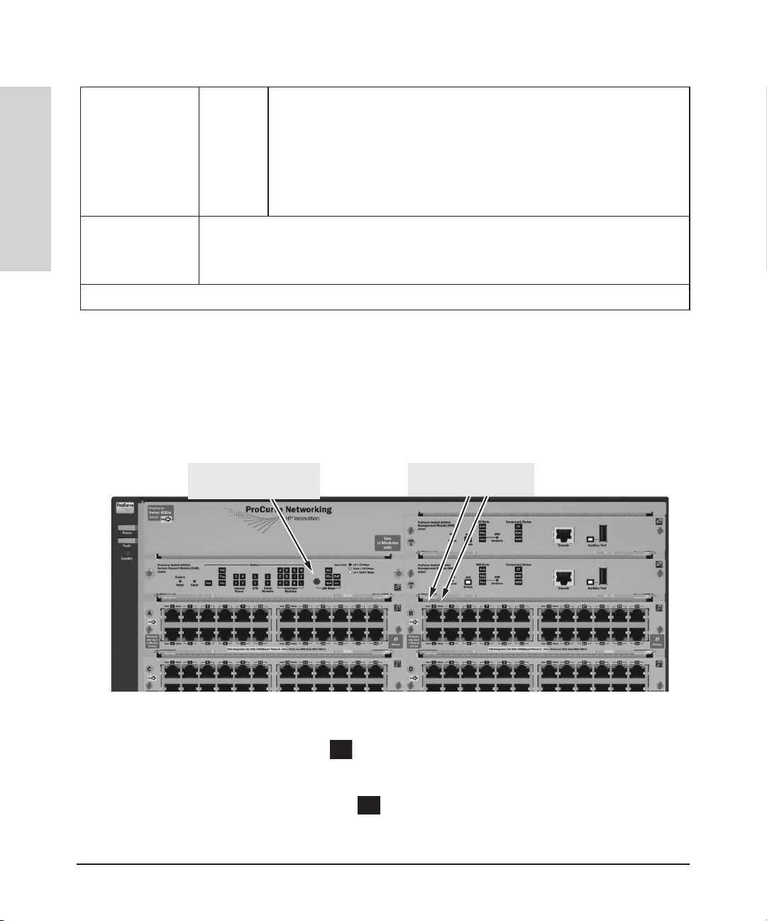
LED Mode Select button
and indicator LEDs
Figure 1-3. Front of 8212 zl Switch, Base System
1-5
Page 17
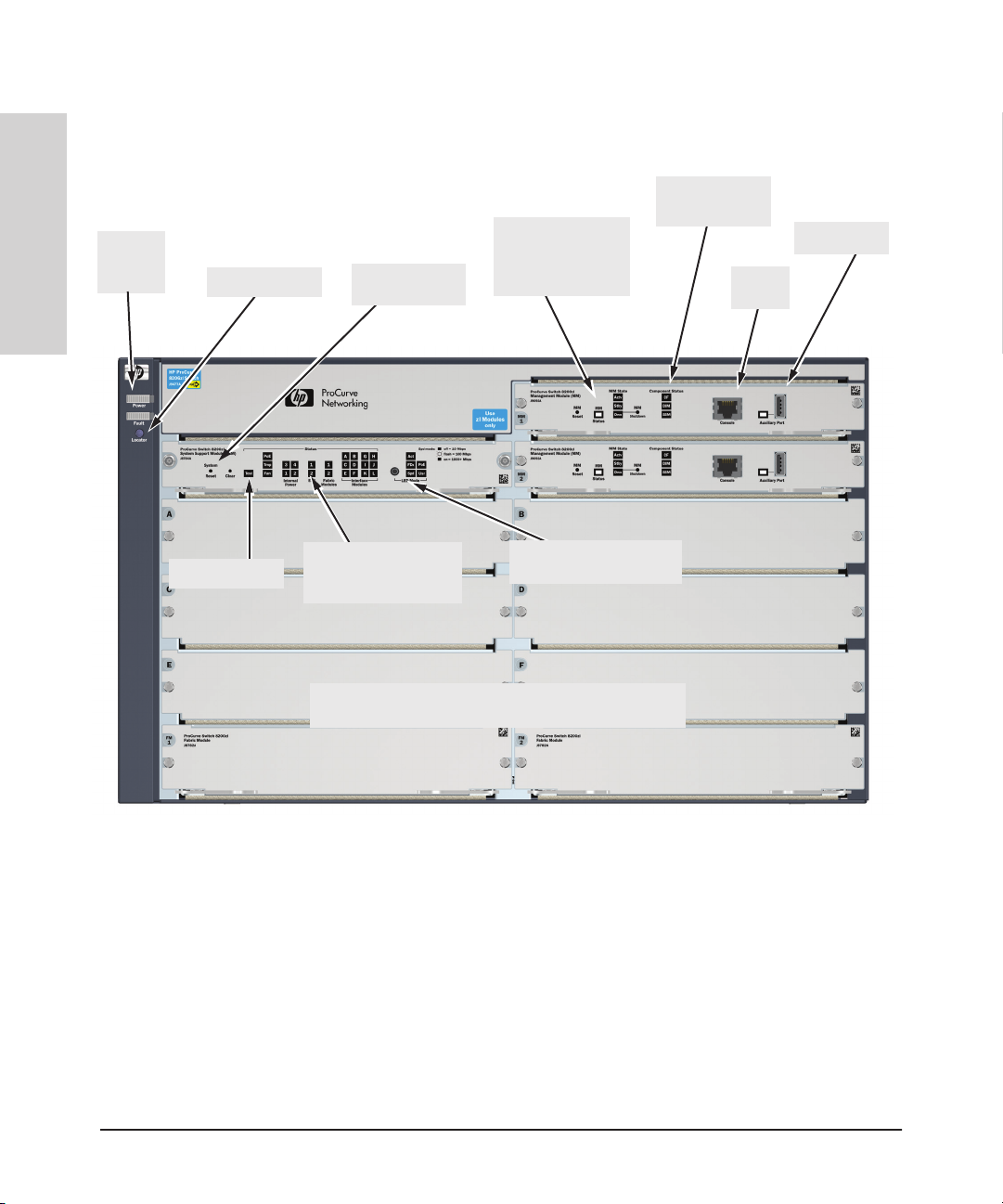
Introducing the HP 8200 zl Switches
Front of the 8200 zl Switches
Power
and Fault
Switches
LEDs
Introducing the HP 8200 zl
Front of 8206 zl Switch, Base System
Management
Module Reset
Locator LED
Reset and Clear
buttons
button, and Status
LEDs
Component
Status LEDs
Auxiliary Port
Console
Port
Self Test LED
Status LEDs for the
Fans, Power Supplies,
and Switch Modules
Switch Modules and slots
with Link and Mode LEDs for each port located on each module
LED Mode Select button
and indicator LEDs
Figure 1-4. Front of 8206 zl Switch, Base System
1-6
Page 18
Introducing the HP 8200 zl Switches
Front of the 8200 zl Switches
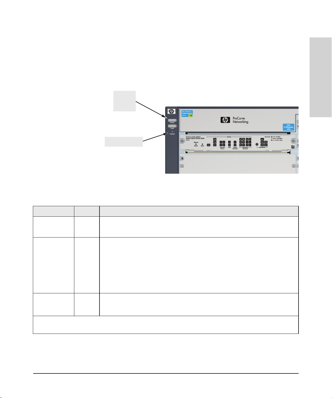
Switch and Module LEDs
As described in the following tables, there are LEDs on the switch chassis and
on the switch modules that keep you informed of the status of the switch and
the network connections.
and Fault
Locator LED
Figure 1-5. Switch Chassis LEDs
Table 1-2. Switch Chassis LEDs
LEDs State Meaning
Introducing the HP 8200 zl
Switches
Power
LEDs
Power
(green)
Fault
(orange)
Locator
(blue)
1
The blinking behavior is an on/off cycle once every 1.6 seconds, approximately.
2
The blinking behavior is an on/off cycle once every 0.5 seconds, approximately.
On The switch is receiving power.
Off The switch is NOT receiving power.
Off The normal state; indicates that there are no fault conditions on the switch.
1
Blinking
On On briefly at the beginning of switch self test after the switch is powered on or reset. If on
On
Blinking
Off
A fault has occurred on the switch, one of the switch modules, an individual port, a power
supply, or a fan. The Status LED for the module or other device with the fault will flash
simultaneously.
for a prolonged time, the switch has encountered a fatal hardware failure, or has failed its
self test. See chapter 5, “T
The Locator LED is used to locate a specific chassis in a area full of chassis. The LED can
be set to be on solid or blink for a specified number of minutes (1-1440). The default is 30
minutes. Use the command “chassislocate”.
roubleshooting” for more information.
1-7
Page 19
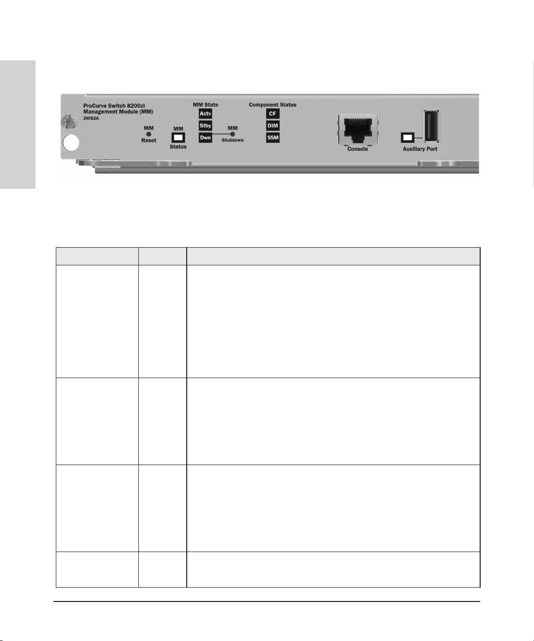
Introducing the HP 8200 zl Switches
Front of the 8200 zl Switches
Switches
Introducing the HP 8200 zl
LED State Meaning
Figure 1-6. Management Module LEDs
Table 1-3. Management Module LEDs.
Auxiliary (green/
orange) For more
information see the
Management and
Configuration Guide
for your switch.
DIM
(green/orange)
CF
(green/orange)
Blinking
green
Indicates the switch is processing a USB command file.
1
On green The switch has finished processing the USB command file successfully.
Blinking
orange
Indicates an error condition.
2
Off Indicates that no USB device has been inserted, or that the inserted USB device
cannot be recognized, or that no command file can be found on the inserted USB
device.
On green DIM (Dual in-line Memory Module) status is known and fault free.
Off DIM status is unknown.
Blinking
orange
If DIM, Fault, and Self Test LEDs are blinking, DIMM failed self-test.
1
If DIM and Fault LEDs are blinking, an operational fault has occurred.
If fast blinking (400ms On and 400ms Off), an operational alert occurred and is
unresolved.
On green CF (CompactFlash) status is known and fault free
Off
Blinking
orange
CF status is unknown.
If CF, Fault, and Self Test LEDs are blinking, CompactFlash failed self-test.
1
If CF and Fault LEDs are blinking, an operational fault has occurred.
If fast blinking (400ms On and 400ms Off), an operational alert occurred and is
unresolved (for example, CompactFlash not present).
SSM
(green/orange)
1-8
On green The communication link with the SSM (system support module) is good.
Off
The communication link with the SSM is bad or there is no SSM installed.
Page 20
Introducing the HP 8200 zl Switches
Front of the 8200 zl Switches
Blinking
orange
Module Status LED On green The Management Module is active and has passed all self-tests.
Blinking
orange
MM State LEDs
(green)(
1
The blinking behavior is an on/off cycle once every 1.6 seconds, approximately.
2
The blinking behavior is an on/off cycle once every 0.5 seconds, approximately.
Actv Indicates the Management Module is active and is the primary management
Stby Indicates that this Management Module is the standby management module.
Dwn Indicates that this Management Module has been shutdown.
The communication link with the SSM is bad or the SSM itself has failed.
1
If Module Status, Fault and Self Test LEDs are blinking, this MM has failed self-test
1
If Module Status and Fault LEDs are blinking, an operational fault has occurred.
module.
Introducing the HP 8200 zl
Switches
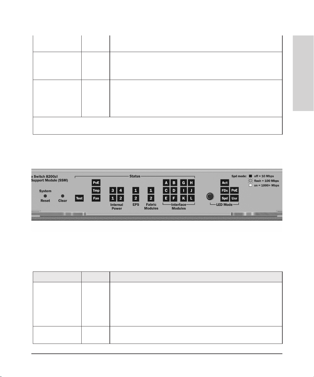
Figure 1-7. System Support Module LEDs
Table 1-4. System Support Module LEDs
These LEDs are located on the System Support Module.
LED State Meaning
Test
(green/orange)
PoE
(green/orange)
Off The normal operational state; the switch is not undergoing self test.
On green The switch self test and initialization are in progress after you have power cycled
On green
Off
or reset the switch. The switch is not operational until this LED goes off. The Self
T
est LED also comes on briefly when you “hot swap” a module into the switch
and the module is automatically self tested.
If any PoE modules are installed.
If no PoE modules are installed.
1-9
Page 21
Introducing the HP 8200 zl Switches
Front of the 8200 zl Switches
Tmp
(green/orange)
Switches
Fan
(green/orange)
Introducing the HP 8200 zl
Internal Power 1-4
(green/orange numbers
corresponding to
the power supply
positions)
EPS (1 and 2)
(green/orange)
Fabric Modules
(1 and 2)
(green/orange)
Blinking
orange
Blinking
orange
Internal PoE fault.
1
External load fault or denied PoE power.
2
Off Switch temperature is normal.
Blinking1An over temperature condition has been detected.
On green The cooling fans are operating normally.
Blinking
orange
One or more of the cooling fans have failed. The switch Fault LED will be blinking
1
simultaneously.
On green A power supply is installed in the position in the back of the switch corresponding
to the number, and the supply is plugged in to an active AC power source. As
shipped, the switch has a single power supply in position 1.
Off A power supply is not installed in the position corresponding to the number.
Blinking
orange
The power supply installed in the position corresponding to the number is not
1
plugged in to an active AC power source, or has experienced a fault. The switch
Fault LED will be blinking simultaneously.
On green
Off
Blinking
orange
On green
Off
Blinking
orange
An External Power Supply is connected.
No External Power Supply is connected.
The External Power Supply has a fault, or is connected but not plugged into AC
1
power.
A Fabric Module is installed and functioning correctly.
A Fabric Module is not installed or has failed.
The Fabric Module has a fault.
1
The switch Fault LED will be blinking simultaneously.
LED Mode Select
(5 green LEDs)
1-10
Act Indicates that the port Mode LEDs are displaying network activity information.
FDx Indicates that the port Mode LEDs are lit for ports that are in Full Duplex Mode.
PoE Indicates which ports are supplying PoE power.
• If the Mode LED is on the port is providing PoE power.
• If the Mode LED is off the port is not providing PoE power.
• If the Link LED is on the port is enabled for PoE.
• If the Link LED is off the port is disabled for PoE.
• If the Link LED is blinking, the port has an error or the port is denied power due
to insufficient power.
Spd Indicates the Port LEDs are displaying the connection speed at which each port
is operating:
• if the Port LED is off, the port is operating at 10 Mbps
• if the Port LED is blinking, the port is operating at 100 Mbps
• if the Port LED is on continuously, the port is operating at 1000 Mbps
Usr Reserved for future development
Page 22
Introducing the HP 8200 zl Switches
Front of the 8200 zl Switches
Modules A-L (green
- letters
corresponding to
On A module is installed in the switch module slot corresponding to the letter and
the module is undergoing or has passed self test. This also occurs when you
install a module when the switch is already powered on (“hot swap”).
the switch module
slots)
In PoE Mode:
1
The blinking behavior is an on/off cycle once every 1.6 seconds, approximately.
2
The blinking behavior is an on/off cycle once every 0.5 seconds, approximately.
Switch Modules with Link and Mode LEDs
for each port located on each module
Off A module is not installed in the switch module slot corresponding to the letter.
1
Blinking
The module status LED flashes very briefly when a module is being hot swapped.
If the LED flashes for a prolonged time, the module in the slot corresponding to
the letter has failed self test or encountered some other fault condition. See
chapter 5, “T
roubleshooting” for a more information.
On green
Blinking
orange
Blinking
orange
Off
PoE is ok for this slot.
PoE internal fault for this slot.
1
PoE load fault or insufficient power for this slot.
2
The module in this slot is not a PoE module.
Introducing the HP 8200 zl
Switches
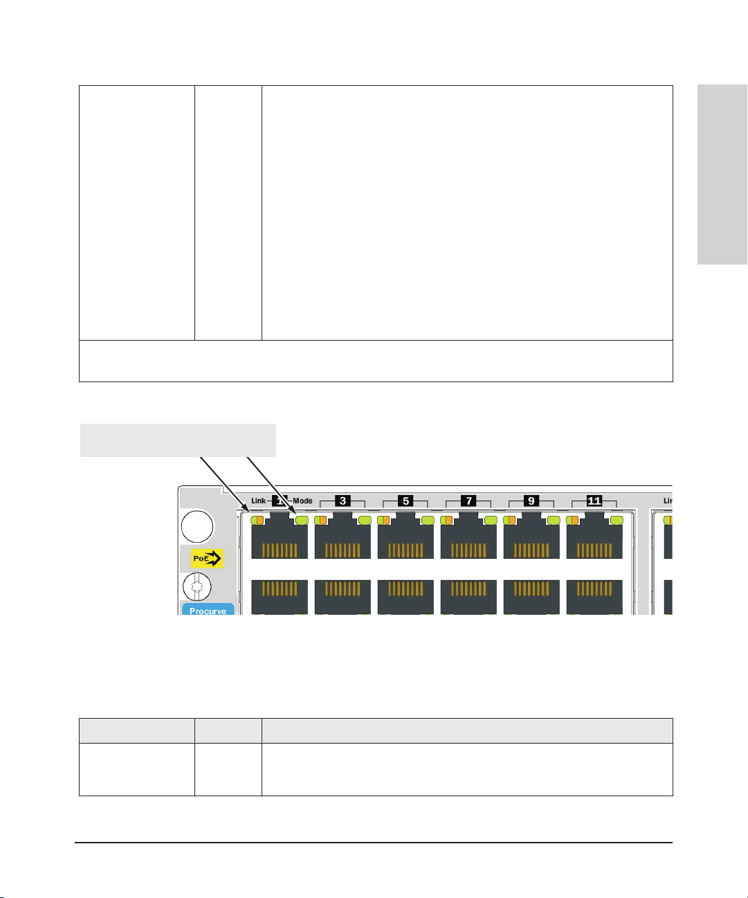
Figure 1-8. Switch Module LEDs
Table 1-5. Switch Module LEDs
These LEDs are located on the modules themselves, one pair for each port.
LED State Meaning
Link On Indicates the port is enabled and receiving a link beat signal (for the twisted-pair
ports), or a strong enough light level (for the fiber-optic ports) from the connected
device.
1-11
Page 23
Introducing the HP 8200 zl Switches
Front of the 8200 zl Switches
Off One of these conditions exists:
• no active network cable is connected to the port
• the port is not receiving link beat or sufficient light
• the port has been disabled through the switch console, the web browser
interface, ProCurve Manager
, or other network management tool.
Switches
Mode Depending on the mode selected, displays the following: network activity information, whether
Introducing the HP 8200 zl
1
The blinking behavior is an on/off cycle once every 1.6 seconds, approximately.
Blinking1The port has failed self test. The switch Fault, Self Test LEDs, and appropriate
the port is configured for Full Duplex operation, maximum speed operation, or whether PoE
power is being supplied or not. See “LED Mode Select Button and Indicator LEDs” below for
more information.
module status LEDs will flash simultaneously.
LED Mode Select Button and Indicator LEDs
To optimize the amount of information that can be displayed for each of the
switch ports, the 8200 zl switches use a Mode LED for each port. The operation
of this LED is controlled by the LED Mode Select button on the switch chassis,
and the current selection is indicated by the mode indicator LEDs near the
button. Press the button to change from one mode to the next.
LED Mode Select button
and indicator LEDs
Mode LEDs
(Link and Mode)
1-12
Figure 1-9. Mode LEDs and LED Mode Select Button
■ If the Activity
Act
indicator LED is lit, each port Mode LED displays
activity information for the port—it flickers as network traffic is received
and transmitted through the port.
■ If the Full Duplex
FDx
indicator LED is lit, the port Mode LEDs light for
those ports that are operating in full duplex.
Page 24

Introducing the HP 8200 zl Switches
Front of the 8200 zl Switches
■ If the speed
indicator LED is lit, the port LEDs behave as follows to
Spd
indicate the connection speed for the port:
• Off = 10 Mbps
• Blinking = 100 Mbps (the blinking behavior is a repeated on/off cycle
once every 0.5 sec.)
• On = 1000 Mbps
■ If the
PoE
indicator LED is lit, the Link and Mode LEDs indicate PoE status:
Link LED:
• On = PoE is enabled on this port
• Off = PoE is disabled on this port.
• Slow Blinking = Internal PoE fault on this port.
• Fast Blinking = This port is denied PoE power or has an external load
fault.
Mode LED:
• On = PoE power is be supplied on this port
• Off = PoE is not being supplied on this port.
Console Port
This port is used to connect a console to the switch by using the serial cable
supplied with the switch. This connection is described under “Connecting a
Console to the Switch” in chapter 2, “Installing the the 8200 zl Switch”. The
console is a full-featured interface that can be used to configure, monitor, and
troubleshoot the switch. It can be run on a PC, laptop, or handheld device
emulating a VT-100 terminal, or on a standard VT-100 terminal.
Introducing the HP 8200 zl
Switches
Reset Buttons
Module Reset
This button, located on the Management module, will reset the Management
module only.
System Reset
This button, located on the System Support Module, will reset the switch when
powered on. This action clears any temporary error conditions that may have
occurred, executes the switch self test, and resets all network activity counters to zero.
The counters are displayed in the switch console interface, the switch web
browser interface, and through SNMP network management applications,
such as ProCurve Manager.
1-13
Page 25

Introducing the HP 8200 zl Switches
Front of the 8200 zl Switches
Switches
Introducing the HP 8200 zl
Press the Reset button also after changing the module type that is installed in
any of the switch module slots while the switch is powered on. In this case,
the switch must be reset to initialize the new module type. See “Hot Swapping
Switch Modules” on page 2-30.
Clear Button
This button, located on the System Support Module, is used for the following
purposes:
■ Deleting Passwords - When pressed by itself for at least one second, the
Clear button deletes any switch console access passwords that you may
have configured. Use this feature if you have misplaced the password and
need console access.
This button is provided for your convenience, but its presence means that
if you are concerned with the security of the switch configuration and
operation, you should make sure the switch is installed in a secure
location, such as a locked wiring closet.
■ Restoring Factory Default Configuration - When pressed with the
Reset button in a specific pattern, the Clear button clears any configuration changes you may have made through the switch console, the web
browser interface, or SNMP management, and restores the factory default
configuration to the switch. For the specific method to restore the factory
default configuration, see “Restoring the Factory Default Configuration”
in chapter 5, “Troubleshooting” of this manual.
1-14
Page 26
Introducing the HP 8200 zl Switches
Back of the 8200 zl Switches
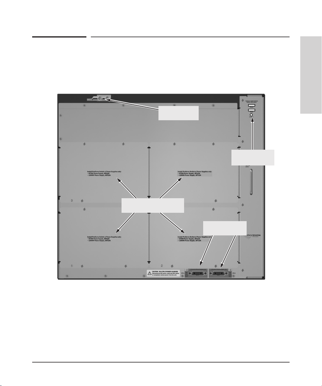
Back of the 8212 zl Switch
Grounding lug
mounting holes
Back of the 8200 zl Switches
Introducing the HP 8200 zl
Switches
Fan Power, Fault
and Locator LEDs
Slots for installing power
supplies
Figure 1-10. Back of an 8212 zl Switch
External PoE
power connectors
1-15
Page 27
Introducing the HP 8200 zl Switches
Back of the 8200 zl Switches
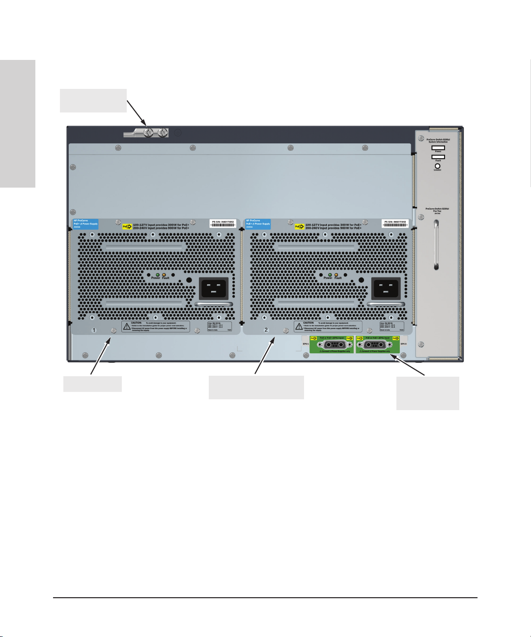
Grounding lug
mounting holes
Switches
Introducing the HP 8200 zl
Back of the 8206 zl Switch
1-16
Power supply
Optional redundant power
supply
External PoE/
PoE+ power
connectors
Figure 1-11. Back of an 8206 zl Switch (shown with two zl Power Supplies)
Power Supply
The 8200 zl switches do not have a power switch. The switches are powered
on when the power supply is connected to an active AC power source. The
8200 zl switches automatically adjust to any voltage between 100-127 and 200240 volts when using the J8712A power supply, between 110-127 and 200-240
volts when using the J9306A power supply, and between only 200-240 volts
when using the J8713A power supply. There are no voltage range settings
required.
Page 28
Introducing the HP 8200 zl Switches
Switch Accessories
Load-sharing redundant power supplies can be installed in the back of the
8200 zl switches or they can be installed externally with the external power
connectors. To provide redundancy, each power supply should be connected
to different AC power sources. Then, if one AC power source fails, the switch
will continue to run.
Caution The switch redundant power supply is hot swappable, but, as indicated by the
caution statement on the power supply, it must be disconnected from AC
power before being installed or removed.
CAUTION:
.
Refer to the installation guide for proper power cord selection
.
Disconnect AC power from the power supply BEFORE installing or
removing the supply. Otherwise, damage to the equipment may result.
Because the switch can run on a single supply, removing a redundant supply
will not interrupt switch operation. However,on the 8212 zl, one power supply
will only supply enough power to run the module slots A-F. Slots G-L will not
receive any power unless there are at least two power supplies installed.
When power is restored from a second (or more) power supplies, a system
reload or interface module reset is required to restore operation to slots G-L.
To reset the interface modules, pull each module out about half way and then
reseat them. Do this for each module in slots G-L.
.
Introducing the HP 8200 zl
Switches
For more information regarding power see the:
■ ProCurve Switch zl Internal Power Supply Installation Guide.
■ HP Power over Ethernet (PoE/PoE+) Planning and Implementation
Guide.
Switch Accessories
Accessories of the 8200 zl switches include eithera6or12-slot chassis for
installing any of the available zl Modules. The supported zl modules include:
■ 24-Port 10/100/1000 PoE+ zl Module (J9307A) -- which can provide Power
over Ethernet (PoE+) power to 802.3at compliant (and some pre-standard) devices.
■ 20-Port 10/100/1000 PoE+/4-Port MiniGBIC zl Module (J9308A)
■ 4-Port 10GbE SFP+ zl Module (J9309A)
■ 24-Port 10/100 PoE+ zl Module (J9478A)
1-17
Page 29

Introducing the HP 8200 zl Switches
Switch Accessories
Switches
Introducing the HP 8200 zl
■ 24-port 10/100/1000-T zl PoE Module (J8702A) -- which can provide Power
over Ethernet (PoE) power to 802.3af compliant (and some pre-standard)
devices.
■ 20-port Gig-T and 4-port mini-GBIC/SFP zl PoE Module (J8705A)
■ 24-port mini-GBIC zl Module (J8706A)
■ 4-port 10Gig-X2 zl Module (J8707A)
■ 4-port 10Gig-CX4 zl Module (J8708A)
■ ONE Services zl Module (J9289A)
■ Redundant Wireless Services zl Module (J9052A)
■ Wireless Edge Services zl Module (J9154x) where “x” is the version letter
A, B, and so on
■ 24-port Gig-T PoE+ v2 zl Module (J9534A)
■ 20-port GT PoE+/4-port SFP v2 zl Module (J9535A)
■ 20-port Gig-T PoE+ / 2-port 10-GbE SFP+ v2 zl Module (J9536A)
■ 24-port SFP v2 zl Module (J9537A)
■ 8-port 10-GbE SFP+ v2 zl Module (J9538A)
■ 8-port 10GBase-T v2 zl Module (J9546A)
■ 24-port 10/100 PoE+ v2 zl Module (9547A)
■ 20-port Gig-T / 2-port 10-GbE SFP+ v2 zl Module (J9548A)
■ 20-port Gig-T / 4-port SFP v2 zl Module (J9549A)
■ 24-port Gig-T v2 zl Module (J9550A)
■ 12-port Gig-T / 12-port SFP v2 zl Module (J9637A)
Note For detailed information about the zl modules, refer to the HP Switch zl
Modules Installation Guide.
For detailed information about PoE and PoE+ devices, refer to the HP Power
over Ethernet (PoE/PoE+) Planning and Implementation Guide.
To view or download this guide, visit www.hp.com/networking/support.
1-18
Page 30

Introducing the HP 8200 zl Switches
Switch Features
Switch Features
The features of the 8200 zl switches include:
■ modules can be installed in any order and in any combination and can be
“hot swapped”
■ supported transceivers can be hot swapped into the mini-GBIC zl Module
■ high performance—With standard zl modules, the 8206 zl Switch has a
routing/switching capacity of 322.8 Gbps, with a switch fabric speed of
345.6 Gbps and a throughput of 240.2 Mpps. With standard zl modules, the
8212 zl Switch has a routing/switching capacity of 645.6 Gbps, with a
switch fabric speed of 691.2 Gbps and a throughput of 480.3 Mpps
With v2 zl modules, the 8206 zl Switch has a routing/switching capacity of
496.8 Gbps, with a switch fabric speed of 561.6 Gbps and a throughput of
396 Mpps. With v2 zl modules, the 8212 zl Switch has a routing/switching
capacity of 993.6 Gbps, with a switch fabric speed of 1123.2 Gbps and a
throughput of 792 Mpps
■ plug-and-play networking—all ports are enabled—just connect the
network cables to active network devices and your switched network is
operational
■ automatic learning of the network addresses in the switch’s 16,000-
address forwarding table, with configurable address aging value
■ full-duplex operation available on all ports
■ easy management of the switch through several available interfaces:
• web browser interface—an easy to use built-in graphical interface
that can be accessed from common web browsers
• console interface—a full featured, easy to use, VT-100 terminal inter-
face for out-of-band switch management, or for TELNET access to
the switch. The console includes complete switch management
through a command line interface (CLI) and a slightly reduced feature
set accessible through an intuitive menu interface
• ProCurve Manager—an SNMP-based graphical interface that is used
to manage your entire network, included with your new switch
• supported by ProCurve Network Manager—an HP OpenView appli-
cation that accurately displays your switch on network maps and
provides a graphical interface for configuring and monitoring your
switch
■ support for the Spanning Tree Protocol to eliminate network loops
Introducing the HP 8200 zl
Switches
1-19
Page 31

Introducing the HP 8200 zl Switches
Switch Features
Switches
Introducing the HP 8200 zl
■ support for up to 2048 VLANs (up to 512 layer-3, IP addressable VLANs)
so you can divide the attached end nodes into logical groupings that fit
your business needs
■ Layer 3 routing functionality:
• IP static routes
• RIP V1 and V2
• IRDP - ICMP Router Discovery Protocol
• OSPF- Open Shortest Path First
• DHCP relay
■ support for many other advanced features to enhance network perfor-
mance, security, and control— for a description, see the Management and
Configuration Guide which is on the HP networking Web site.
■ support for IEEE 802.3af standard, IEEE 802.3at standard, and pre-stan-
dard PoE devices
1-20
Page 32

Installing the HP 8200 zl Switches
The 8200 zl switches are easy to install. Each comes with an accessory kit that
includes the brackets for mounting the switch in a standard 19-inch telco rack,
or in an equipment cabinet. The switch has rubber feet already attached so
they can be securely located on a horizontal surface. This chapter tells you
how to install your 8212 zl or 8206 zl switch.
2
WARNING To avoid possible personal injury, be careful when lifting the chassis
out of the shipping box. The Switch 8212 zl chassis base system weighs
approximately 50.45 pounds as shipped and 44.75 pounds when empty.
See “Installation Precautions” on page 2-5 for additional safety
considerations when handling this product.
Included Parts
The following components are shipped with the 8200 zl switches:
■ HP 8212 zl Quick Setup Guide or HP 8206 zl Quick Setup Guide
■ HP 8200 zl Safety and Regulatory Information
■ Accessory kit (5070-6865 for the 8206 zl or 5070-2983 for the 8212 zl):
• two mounting brackets
• eight 10 mm M4 screws to attach the mounting brackets to the switch
• eight 5/8-inch number 12-24 screws to attach the switch to a rack
■ Console cable
Installing the HP 8200 zl
Switches
2-1
Page 33

Installing the HP 8200 zl Switches
Power Cords
Note Power supplies for 8200 zl Switches must be ordered separately.The following
Switches
Installing the HP 8200 zl
Power Cords
power cords are provided with those power supplies.
Power cord, one of the following:
Region Cable Cable Cable
Australia/New Zealand
China
Continental Europe
Denmark
Japan
Switzerland
United Kingdom/Hong Kong/Singapore
United States/Canada/Mexico
South Africa
Taiwan
Israel
Thailand
Argentina
Brazil
Chile
J8712A Power
Supply
8121-0857
8121-1034
8120-5336
8120-5340
8120-5342
8120-5339
8120-5334
8121-0973
8120-5341
8121-0941
8121-1009
8121-0671
8120-8375
8121-1132
8120-8389
J8713A Power
Supply
8121-0871
8121-0924
8120-6899
8120-6897
8120-6903
8120-6897
8120-6898
8120-6903
8121-0915
8120-6903
8121-1010
8121-0675
8121-0912
8121-1100
8121-0876
J9306A Power
Supply
8121-0857
8121-1034
8120-5336
8120-5340
8121-0941
8120-5339
8120-5334
8121-0973
8120-5341
8121-0967
8121-1009
8121-0671
8120-8375
8121-1132
8120-8389
1
2
Japan Power
Cord Warning
2-2
1
Japan: NEMA L6-20P, 200V.
2
A NEMA L6-20, 240V power cord is also available. Order part number 8121-0941. To
order go to www.hp.com/buy/parts.
Page 34

Installing the HP 8200 zl Switches
Installation Procedures
Installation Procedures
WARNING To avoid personal injury or product damage, read the safety warnings
on page 2-5 and installation precautions on page 2-6 and follow the
rack mounting guidelines on page 2-7. Due to product weight, two or
more persons are required to handle and mount the 8212 zl.
Summary
Follow these easy steps to install your switch. The rest of this chapter provides
details on these steps.
1. Prepare the Installation Site (page 2-7). Make sure the physical
environment into which you will be installing the switch is properly
prepared including having the correct network cabling ready to connect
to the switch, and having a good location for the switch.
2. Mount the Switch Chassis (page 2-7). The 8200 zl switches are large,
heavy chassis. HP networking recommends mounting the empty chassis
before populating it with modules or power supplies. It can be mounted
in a 19-inch telco rack, in an equipment cabinet, or on a horizontal surface.
An optional Rail Mounting Kit (5070-0145) is available for mounting the
8200 zl switches in a cabinet that is suitable for shipping.
3. Install the Switch Modules (page 2-11). The 8200 zl switches have
either six or twelve universal slots for installing any of the HP zl Modules.
Depending on where you will install your 8200 zl switch, it may be easier
to install the modules first. The modules are “hot swappable” though, so
they may also be installed and removed after the switch is powered on.
4. Install the Power Supplies (page 2-14). The 8212 zl switch supports
four power supplies. The 8206 zl switch supports two power supplies. It
may be easier to install the power supplies before mounting the switch.
The switch must have at least one power supply to operate some of the
modules.
Installing the HP 8200 zl
Switches
5. Verify the Switch Passes Self Test (page 2-17). This is a simple process
of plugging the switch into a power source and observing that the LEDs
on the switch’s front panel and on the modules show correct operation.
It may be easier to verify if the switch passes self test before mounting
the switch.
2-3
Page 35

Installing the HP 8200 zl Switches
Installation Procedures
Note The 10/100/1000-T ports on the zl Modules comply with IEEE 802.3x
Switches
Installing the HP 8200 zl
6. Install the Grounding Wire (page 2-20). If a grounding wire is to be
attached to the switch chassis, the grounding lug must be removed and a
wire crimped to it and the grounding lug must be reinstalled.
7. Connect the Switch to a Power Source (page 2-21). Once the switch
is mounted, plug it in to the nearby main power source.
8. (Optional) Connect a Power Supply Shelf (page 2-21). Youmay wish
to use a Switch zl Power Supply Shelf (J8714A) with your switch. To do
so, you must connect the external power supply using the EPS cables
supplied with the Power Supply Shelf.
9. Connect the Network Devices (page 2-25). Using the appropriate
network cables, connect other switches, hubs, routers, computers,
servers, printers, and other network devices to the switch ports. For more
information, see “Connect the Network Devices” on page 2-25.
standard which includes the Auto MDI/MDI-X feature. This feature
allows you to use straight-through twisted-pair cable for all of your
twisted-pair network connections.
10. (Optional) Connect a Console to the Switch (page 2-27). You may
wish to modify the switch’sconfiguration, for example, to configure an IP
address so it can be managed using a web browser or from an SNMP
network management station. Configuration changes can be made easily
through the switch’s console interface.
2-4
At this point, the switch is fully installed. See the rest of this chapter if you
need more detailed information on any of these installation steps.
Page 36

Installing the HP 8200 zl Switches
Installation Procedures
Installation Precautions
To prevent personal injury, follow these precautions when installing the 8212
zl switch:
WARNINGs
■ Due to product weight, two or more persons are required to handle
and mount the 8212 zl switch. To reduce the weight, remove all
modules and power supplies.
■ Devices installed in a rack or cabinet should be mounted as low
as possible, with the heaviest device at the bottom and progressively lighter devices installed above.
The rack or cabinet should be adequately secured to prevent it
from becoming unstable and/or falling over.
■ Ensure a cover plate is installed on any empty switch power
supply or module slot. A cover plate is required for safe
operation, and to ensure proper switch cooling. Never have
more than one power supply or module slot uncovered at a
time while the switch is powered on.
■ To avoid energy and mechanical hazards, never allow any part
of your body, jewelry, tool, or other foreign object to enter any
module or power supply slots.
■ This unit may have more than one power supply cable. To fully
power down the switch, you must disconnect all power supply
cables from the unit.
Installing the HP 8200 zl
Switches
2-5
Page 37

Installing the HP 8200 zl Switches
Installation Procedures
Installation Precautions (continued)
Cautions
Switches
Installing the HP 8200 zl
■ If the switch is to be shipped in a rack, use only an HP 10000 series rack
and a rail mounting kit (5070-0145) for each switch and ensure the power
supplies have been removed before shipping.
■ Ensure the power source circuits are properly grounded, then use the
power cord supplied with the switch to connect it to the power source.
■ If your installation requires a different power cord than the one supplied
with the switch and power supply, be sure the cord is adequately sized
for the switch’s current requirements. In addition, be sure to use a power
cord displaying the mark of the safety agency that defines the regulations
for power cords in your country. The mark is your assurance that the
power cord can be used safely with the switch and power supply.
■ When installing the switch, note that the AC outlet should be near the
switch and should be easily accessible in case the switch must be
powered off.
■ Ensure the switch does not overload the power circuits, wiring, and over-
current protection. Each power supply should be connected to a dedicated branch circuit to prevent tripping building circuit breakers. To
determine the possibility of overloading the supply circuits, add together
the ampere ratings of all devices installed on the same circuit as the
switch and compare the total with the rating limit for the circuit. The
maximum ampere ratings are usually printed on the devices near the AC
power connectors.
2-6
■ Do not install the switch in an environment where the operating ambient
temperature might exceed 45C (113F).
■ Allow three to four inches of space around the sides and back of the
switch to make sure the air flow for the switch is not restricted.
Page 38

Installing the HP 8200 zl Switches
Installation Procedures
1. Prepare the Installation Site
Cabling Infrastructure
Ensure the cabling infrastructure meets the necessary network specifications.
See Appendix C, “Cabling and Technology Information” on page B-1 for more
information.
Installation Location
Before installing the switch, plan its location and orientation relative to other
devices and equipment:
■ In the front of the switch, allow at least 7.6 cm (3 inches) of space for the
twisted-pair and fiber-optic cabling.
■ In the back of the switch, allow at least 10.2 cm (4 inches) of space for the
power cord and cooling.
■ On the sides of the switch, leave at least 7.6 cm (3 inches) for cooling.
2. Mount the Switch Chassis
Installing the HP 8200 zl
Switches
The HP 8200 zl switches have large, heavy chassis; therefore, HP networking
recommends mounting the switch before populating it with modules or power
supplies.
WARNING A base system weighs approximately 50 pounds, and an unloaded
chassis weighs approximately 44 pounds. Toavoid personal injury,plan
on having at least two people available to help move the unit into place
onto the rack. TWO OR MORE PEOPLE ARE REQUIRED WHEN
MOUNTING THIS SWITCH.
The 8200 zl switches can be mounted in these ways:
■ in a rack or cabinet
■ on a horizontal surface
Rack or Cabinet Mounting
The 8200 zl switches are designed to be mounted in any EIA-standard
19-inch telco rack or in an equipment cabinet such as a server cabinet. If you
are installing the switch in an equipment cabinet, read the following “Equipment Cabinet Note” on page 2-8.
2-7
Page 39

Installing the HP 8200 zl Switches
Installation Procedures
Equipment
Cabinet
Note
WARNING For safe operation, please read the “Installation Precautions” on page
Switches
Installing the HP 8200 zl
If you are installing the switch in an equipment cabinet, in place of the 1224 screws supplied with the switch, use the clips and screws that came with
the cabinet. Plan which four holes you will be using in the cabinet and install
all four clips and partially install the two bottom screws, as described in step
2 on the previous page, before proceeding to step 3.
2-5 and page 2-6 before mounting the switch.
1. Use a #1 Phillips (cross-head) screwdriver and attach the mounting
brackets to the switch with the included 8-mm M4 screws.
For the 8200 zl switches, each bracket is attached with four screws as
shown in the following illustrated example.
2-8
8 mm
M4 screws
Figure 2-1. Attaching Brackets to the 8212 zl Switch
Page 40

2. Partially install a screw into the top hole of a pair of holes that are 0.5
inches apart in each rack/cabinet upright as shown in the illustration
below. Ensure that the screws are at the same level in each upright.
Partially install a screw
into the top hole of a
close (0.5-inch) pair on
both sides of the rack
Figure 2-2. Mounting Screw Positioning
Installing the HP 8200 zl Switches
Installation Procedures
Installing the HP 8200 zl
Switches
3. Place the switch in the rack and lower it so the notches in the bottom of
lower the switch with
mounting brackets onto the
partially installed screws,
then tighten these screws
Figure 2-3. Notches in Bracket Being Installed
the bracket slide onto the screws, then tighten these screws.
2-9
Page 41

Installing the HP 8200 zl Switches
Installation Procedures
Switches
Installing the HP 8200 zl
4. Install the other screw into the upper hole in each bracket. Tighten these
screws.
install and tighten the
other 12-24 screws
Figure 2-4. Screws in Bracket Being Installed
Horizontal Surface Mounting
Place the switch on a table or other horizontal surface. Use a sturdy surface
in an uncluttered area. You may want to secure the networking cables and
switch power cord to the table legs or other part of the surface structure to
help prevent people from tripping over the cords.
Note Ensure the air flow is not restricted around the sides and back of the switch.
2-10
Page 42

3. Install the Switch Modules
Install switch modules into the slots as shown in the illustration below. For
installation details, see the instructions in the manual that comes with the
module.
Caution Make sure you install only HP Switch zl Modules.
Avoid any electrostatic discharge problems by handling the modules only by
their bulkheads.
The slot cover can be removed, and the module can be installed with either a
flat-bladed or Torx T-10 screwdriver. Retain the slot cover for future use.
Installing the HP 8200 zl Switches
Installation Procedures
Installing the HP 8200 zl
Module
Installation
Notes
■ Any of the supported Switch zl Modules can be installed in any of the slots.
■ The modules can be “hot swapped”, installed after the switch is already
powered on, and normally will be immediately operational. But, if you are
replacing a module with a different type than what was previously
installed in the slot, the switch must be rebooted after the module is
installed. See “Hot Swapping the Switch Module” on page 2-30.
■ Ensure you fully insert the modules. That is, press the module into
the slot using the extractor handles, until the bulkhead on the module is
contacting the front face of the switch chassis.
■ Once the module is fully inserted, screw in the two retaining screws to
secure the module in place. The screws should be tightened until they are
secure, but not overtightened.
■ If you do not use one or more of the slots, ensure the slot cover plate is
still attached over the slot for safe operation and proper switch cooling.
For safety, you should not have more than one module slot uncovered at
a time.
■ Although these procedures show the 6-slot chassis, the procedures are
the same for the 12-slot chassis.
Switches
2-11
Page 43

Installing the HP 8200 zl Switches
Installation Procedures
Insert module into the guides and
slide it in until it is fully inserted.
Switches
Installing the HP 8200 zl
Use the extractor handles to
seat the module completely.
Open extractor handles
Figure 2-1. Module Being Installed in a Chassis
Then tighten the retaining screws
on the module until they are secure,
but do not overtighten them.
2-12
Figure 2-5. Chassis with Module Fully Installed
Page 44

Installing the HP 8200 zl Switches
Installation Procedures
Installing a Management Module Battery
The battery on the management module is used to keep time for the internal
switch clock. There is no indicator LED for when the battery dies. The only
indication will be the internal clock will not keep the correct time.
WARNING ■ The battery requires special handling at end-of-life. The battery
can explode or cause burns if disassembled, charged, or exposed
to water, fire or high temperature. After replacing the battery,
properly dispose of used battery according to instructions.
■ There is a risk of explosion if the battery is replaced by an
incorrect type. Ensure to replace the battery with the same type.
■ To avoid shorting of battery, remove and properly dispose of
battery before returning the Management Module for repair.
To install a New Battery:
1. Insert the new battery with the lettering and the plus “+” sign facing up.
2. Install the management module into the switch.
Installing the HP 8200 zl
Switches
Figure 2-6. Battery Location on Management Module
2-13
Page 45

Installing the HP 8200 zl Switches
Installation Procedures
ATTENTION ll y a danger d'explosion s'il y a remplacement incorrect de la batterie.
ATTENTION If this product contains a real-time clock battery or coin cell battery it may
Switches
Installing the HP 8200 zl
Remplacer uniquement avec une batterie du même type ou d'un type
équivalent recommandé par le constructeur.
Mettre au rebut les batteries usagées conformément aux instructions du
fabricant.
contain perchlorate and may require special handling when recycled or
disposed of in California and other certain states.
Perchlorate material - special handling may apply see:
www.dtsc.ca.gov/hazardouswaste/perchlorate Web site for more
information.
4. Install the Power Supplies
Both the 8212 zl switch and the 8206 zl switch can use any of these HP switch
zl power supplies:
■ The J9306A, 1500W PoE+ zl Power Supply, which delivers the following
PoE+:
• up to 300 watts at 110-127 volts
• up to 900 watts at 200-240 volts
■ The J8712A, 875 W Power Supply, which delivers up to 273 watts of PoE
power.
■ The J8713A, 1500 W Power Supply, which delivers up to 900 watts of PoE
power at 220 volts.
Caution The J8712A and J8713A power supplies can be paired within the same switch
or within the Power Supply Shelf. However, the J9306A power supply can only
be paired with another J9306A power supply within the same switch or within
the Power Supply Shelf. The J9306A power supply cannot be used with either
the J8712A or J8713A power supplies.
The HP 8212 zl switch has limited operation on a single power supply. Only
the first six module slots (A-F) will be powered when using only one power
supply. In order to power all 12 module slots, the 8212 zl switch requires two
2-14
Page 46

Installing the HP 8200 zl Switches
Installation Procedures
power supplies installed in the switch. When there are two power supplies
installed in the switch and one should fail, the other power supply can keep
the switch running with the first six module slots operational. The 8212 zl
switch can hold up to four, load-sharing power supplies. Install the second
power supply into power slot number 2, as shown in Figure 2-3. Be sure to use
the same power supplies in any one switch.
The HP 8206 zl switch has full operation on a single power supply. However,
a second, redundant power supply will prevent the switch from losing all
operation should the main power supply fail. The 8212 zl can hold up to two,
load-sharing power supplies. Be sure to use the same power supply model in
any one switch.
The power supply slot covers can be removed with either a flat-bladed or Torx
T-10 screwdriver. Retain the slot covers for future use.
To prevent overloading of the building circuits, the second power supply can
be connected to a different AC power source than the first power supply. This
also helps with redundancy where in the event of one power source failure,
the switch will continue to operate.
Installing the HP 8200 zl
Switches
Caution The 8200 zl switches are designed to provide continuously operating PoE or
PoE+ power in the event of a single power supply failure with only a loss of
PoE power to lower priority ports.
If more than one power supply fails while the switch is at or near maximum
operating power (that is: the sum total of all PoE or PoE+ supply capacity
minus the largest supply, see chapter 2 and 4 of the HP Power over Ethernet
(PoE/PoE+) Planning and Implementation Guide) loss of all PoE or PoE+
power may result.
To return PoE or PoE+ power to the ports without causing the switch to
reboot, when there are two or more power supplies still supplying 12V power,
unplug the power cord for 5 seconds and re-plug it for each power supply one
at a time.
2-15
Page 47

Installing the HP 8200 zl Switches
Installation Procedures
Caution The switch power supplies are hot swappable; they can be installed while the
Switches
Installing the HP 8200 zl
switch is receiving power from the supply in the other slot. But, as indicated
by the caution statement on the power supply, the supply must not be
connected to AC power before being installed or removed.
CAUTION:
.
Refer to the installation guide for proper power cord selection
.
Disconnect AC power from the power supply BEFORE installing or
removing the supply. Otherwise, damage to the equipment may result.
For safety and proper switch cooling, if either of the power supply slots are
not being used, make sure to attach the cover plate over the slot. Please see
the “Installation Precautions” on page 2-6 for more information.
For installation details, see the instructions in the manual that comes with the
power supply.
.
Insert the power supply into the
opening, then slide it all the way in
until it connects to the switch. The
power supply face plate will be
flush with the back face of the
switch.
2-16
Figure 2-7. Installing a Power Supply
Page 48

Installing the HP 8200 zl Switches
Installation Procedures
Once the power supply is installed, tighten the four retaining screws that hold
it in place. The screws can be tightened with either a flat-bladed or Torx T-10
screwdriver. Be careful not to overtighten the screws.
tighten the four screws
Figure 2-8. Back of Switch with Power Supply Fully Installed
Installing the HP 8200 zl
Switches
5. Verify the Switch Passes Self Test
After you have installed any modules and the optional second power supply,
but before mounting the switch in its network location, you should first verify
it is working properly by plugging it into a power source and verifying it passes
its self test.
If you have installed a second power supply, repeat these procedures with the
second power supply to verify it works correctly also.
1. Connect the power cord supplied with the switch to the power connector
on the back of the switch, and then into a properly grounded electrical
outlet.
2-17
Page 49

Installing the HP 8200 zl Switches
Installation Procedures
Switches
Note The 8200 zl switches do not have a power on-off switch. It is powered on when
Installing the HP 8200 zl
Connect power cord to
power connector
Figure 2-9. Power Connector on Back of Switch
the power cord is connected to the switch and to a power source.
If your installation requires a different power cord than the one supplied with
the switch, please see the “Installation Precautions” on page 2-6.
2. Check the LEDs on the switch and on each of the switch modules. The
LED behavior is described on the next page.
If the LED display is different than what is described, especially if the
Fault LED stays on for more than approximately 120 seconds or it starts
blinking, the self test has not completed correctly. Refer to chapter 5,
“Troubleshooting” for diagnostic help.
2-18
Page 50

Installing the HP 8200 zl Switches
Installation Procedures
Switch Fault LED
Switch Chassis LEDs
Switch Module LEDs:
Link and Mode LEDs
for each port
Figure 2-10. Switch Fault, Module, and Chassis LEDs
When the switch is powered on, it performs its diagnostic self test. The entire
download, initialization, and self test process can take up to 2 minutes for a
fully loaded chassis, depending on the number and type of modules installed
in the switch.
Installing the HP 8200 zl
Switches
LED Behavior:
During the self test:
■ Initially, Power, Fault, Locator, and all the switch chassisLEDs are on. Then,
after approximately 30 seconds, all the module LEDs go on as the modules
receive power and code is downloaded to them, the Fault LED goes off,
and the chassis LEDs turn orange and then go off except Test, Fan, and
Power, which turn green.
■ When the download of code to the modules is completed, the module
LEDs go off. You may see each port LED go on briefly,in sequence, as the
port is tested.
■ For the duration of the self test, the Test LED stays on.
2-19
Page 51

Installing the HP 8200 zl Switches
Installation Procedures
When the test completes successfully:
■ The Power LED stays on, and the Status LEDs on the switch chassis stay
■ The Fault, Locator, and Test LEDs are off.
■ The port LEDs on the switch modules go into their normal operational
6. Install the Grounding Wire
on for the devices installed: one for each switch module installed, one for
each power supply installed, and one for all the fans.
mode:
• If the ports are connected to active network devices, the Link LEDs
stay on and the Mode LEDs behave according to the mode selected.
In the default mode (Activity), the Mode LEDs should flicker showing
network activity on the port.
• If the ports are not connected to active network devices, the LEDs
will stay off.
Switches
Installing the HP 8200 zl
If a grounding wire is to be attached to the switch chassis, the grounding lug
must be removed and a wire crimped to it and the grounding lug must be
reinstalled.
1. Use a #1 Phillips (cross-head) screwdriver and remove the grounding lug
and two screws from the back of the switch.
2. Crimp the grounding lug to a properly grounded grounding wire.
3. Re-attach the grounding lug to the switch with the two screws.
Grounding lug
Figure 2-11. Attaching Grounding Lug to the 8200 zl Switch
Grounding
lug screws
2-20
Page 52

Installing the HP 8200 zl Switches
Installation Procedures
7. Connect the Switch to a Power Source
1. Plug the included power cord into the switch’s power connector and into
a nearby properly grounded AC power source.
If a redundant power source is available, it is desirable to power one
switch power supply from the regular AC source, and the other power
supply from the redundant AC source. This will provide redundancy in AC
power to the switch, as long as the switch PoE power usage falls within
the capability of one power supply. If both power supplies are plugged
into a common AC source, there is still power supply redundancy,that is,
protection against power supply failure, but if the AC source fails, the
switch will lose all power.
2. Re-check the LEDs during self test. See “LED Behavior” on page 2-19.
8. (Optional) Connect a Power Supply Shelf
to the switch
1. Connect the supplied external power supply (EPS) cables to the switch
and to the Power Supply Shelf.
Installing the HP 8200 zl
Switches
2. Tighten the thumb screws on all connectors to prevent any accidental
disconnects.
3. Plug the power supply cords into the power connector and into a nearby
properly grounded AC power source.
The HP ProCurve Switch zl Power Supply Shelf (EPS) (J8714A) is an
accessory product for the 8200 zl switches. The EPS provides External Powerover-Ethernet (PoE) power for up to two 8200 zl switch products.
The EPS can supply up to 1800 watts (depending upon which power supplies
are installed) of PoE power to the switch if the internal PoE power supply
should fail, or as additional PoE power to be made available to the switch’s
PoE ports. For further information regarding the EPS PoE capabilities, see
the HP Power over Ethernet (PoE/PoE+) Planning and Implementation
Guide and the ProCurve Power Supply Shelf Installation and Getting Started
Guide, which are on the HP networking Web site at www.hp.com/networking/
support.
The EPS is an unmanaged power supply that only provides information by
way of LEDs.
2-21
Page 53

Installing the HP 8200 zl Switches
Installation Procedures
Caution Disconnecting the EPS (PoE power) cable with power flowing is not
Switches
Installing the HP 8200 zl
EPS Operation
The EPS has a mechanism for detecting that it is connected to a valid switch
with an EPS cable. When the EPS is connected to a powered switch it will
provide additional PoE power to the switch within 2 seconds.
supported, and could cause loss of PoE power to all network devices
connected to the switch. The Power Supply Shelf must be powered down
before disconnecting the EPS (PoE power) cable, if power is flowing. Only
the power supply to be disconnected must be powered down. The EPS cable
may be connected at any time.
Operating Characteristics of the EPS (J8714A)
The Power Supply Shelf has two EPS Ports. The EPS can provide a maximum
of up to 900 watts of PoE power to each of the two EPS ports depending on
which power supply is used. It is important to understand the PoE power
requirements of the 8200 zl switches because if the PoE power is not planned
and implemented correctly the end devices connected to the switch ports may
not receive power if an internal switch PoE power supply should fail. For
further information regarding the Power Supply Shelf PoE capabilities, see
the HP Power over Ethernet (PoE/PoE+) Planning and Implementation
Guide and the ProCurve Power Supply Shelf Installation and Getting Started
Guide, which is on the HP networking Web site.
2-22
Power Supply Shelf LEDs
The EPS LEDs are duplicated on the front and back of the device. The
following graphic shows an example of the front of the EPS. There are two
dual colored (green/orange) LEDs for each EPS port:
■ Device Connected
■ Power Status
Page 54

Installing the HP 8200 zl Switches
Installation Procedures
ProCurve Switch zl
Power Supply Shelf
J8714A
PoE
Power
Power
Fault
Fault
Power
EPS Port
Supply
Status
Status
Device Connected
E1 E2
Power Status
Installing the HP 8200 zl
Device Connected LEDsPower Status LEDs
Switches
2-23
Page 55

Installing the HP 8200 zl Switches
Installation Procedures
Switches
Installing the HP 8200 zl
Connecting the Power Supply Shelf
8200 zl
To Power
Source
To Power
Source
To Power Source
EPS Cables
2-24
Figure 2-12. Connecting the EPS to one 8200 zl switch
Page 56
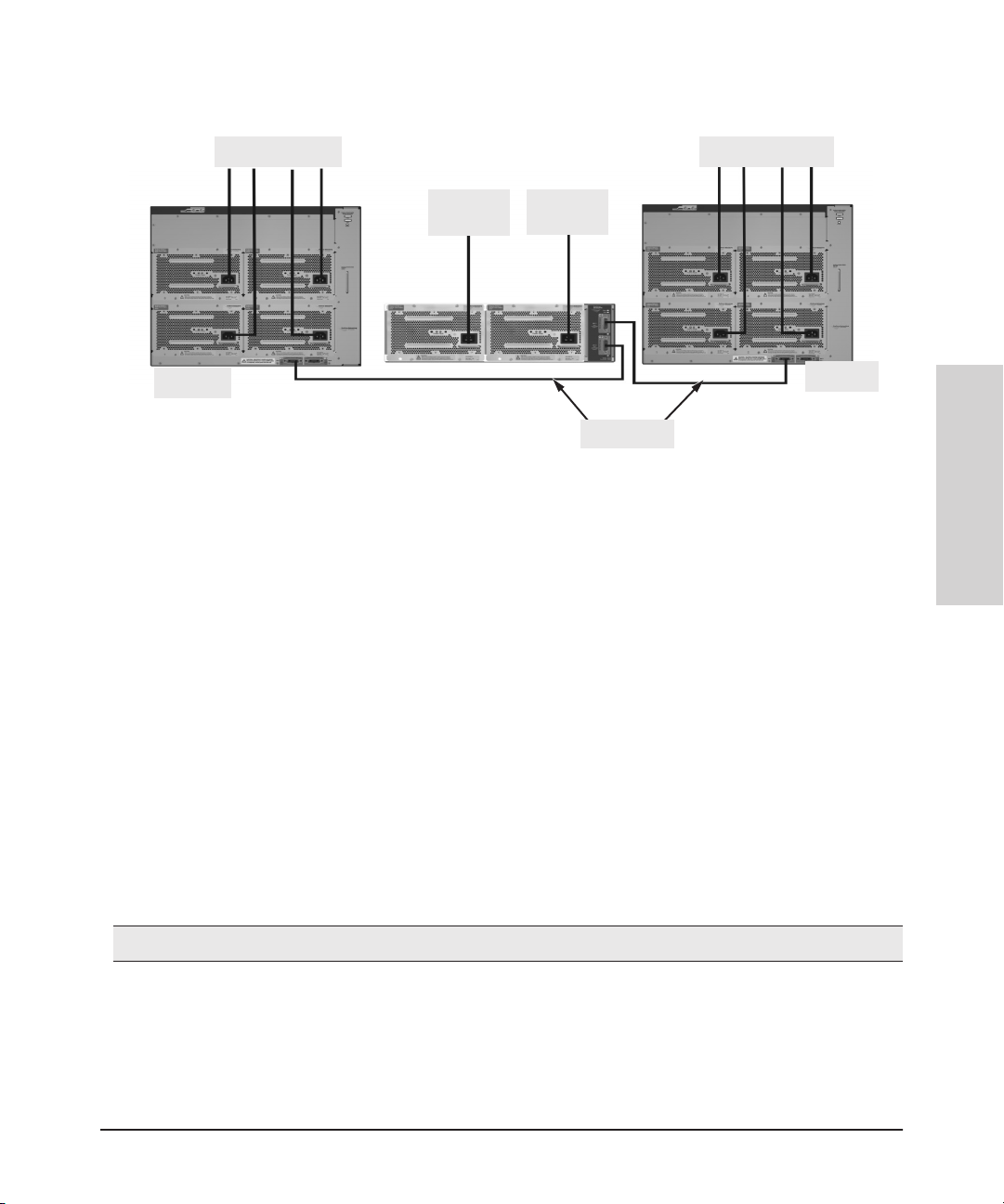
Installing the HP 8200 zl Switches
Installation Procedures
8200 zl
To Power Source
To Power
Source
To Power
Source
EPS Cables
To Power Source
Figure 2-13. Connecting the EPS to two 8200 zl switches
These examples show the switch and the EPS using the J8713A power supply,
the J8712A power supply can also be used. It depends on how much PoE
power is required.
For more information on PoE requirements see the HP Power over Ethernet
(PoE/PoE+) Planning and Implementation Guide.
8200 zl
Installing the HP 8200 zl
Switches
9. Connect the Network Devices
The type of network connections you will need to use depends on the types
of switch modules you have installed in your 8200 zl switch. See the documentation accompanying the modules for cabling configurations and procedures
for those modules.
In general for all the modules, when a network cable from an active network
device is connected to the switch, the Link LED for the switch port should go
on. If the Link LED does not go on, use the table below to help solve the
problem, and see the module documentation for troubleshooting procedures.
Condition Diagnostic Tip
2-25
Page 57

Installing the HP 8200 zl Switches
Installation Procedures
Port LED is
still off when
a cable is
connected
Switches
Installing the HP 8200 zl
Try the following procedures:
• For the indicated port, verify both ends of the cabling, at the switch and the connected device, are
securely connected.
• Verify the connected device and switch are both powered on and operating correctly.
• Verify you have used the correct cable type for the connection:
– for all twisted-pair connections, the RJ-45 connectors on the 8200 zl switch allow you to use
either straight-through cable or crossover cable when the port is in the “Auto” configuration.
– for fiber-optic connections, verify the transmit port on the switch is connected to
the receive port on the connected device, and the switch receive port is connected to
the transmit port on the connected device.
See appendix B, “Switch Ports and Network Cables” for information on cables.
• Verify the port has not been disabled through a switch configuration change.
• Verify the connection parameters in the configurations of the switch port and the connected
device match. Mismatched configurations are a frequent cause of connection problems.
You can use the console interface, or, if you have configured an IP address on the switch, use the
web browser interface, or ProCurve Manager network management software to determine the
state and configuration of the port and re-enable the port if necessary.
• If the other procedures don’t resolve the problem, try using a different port or a different cable.
2-26
Page 58

Installing the HP 8200 zl Switches
Installation Procedures
10. (Optional) Connect a Console to the Switch
The 8200 zl switch has a full-featured, easy-to-use console interface for
performing the following tasks.
■ Monitor switch and port status and observe network activity counters
■ Modify the switch’s configuration
■ Read the event log and access diagnostic tools to help in troubleshooting
■ Download new software to the switch
■ Add passwords and other security features to control access to the switch
from the console, web browser interface, and network management
stations
The console can be accessed through these methods:
■ Out-of-band: Connect a PC or VT-100 terminal, to be used as a console,
directly to the switch using the serial cable that comes with the 8200 zl
switch. If the PC or terminal has a 25-pin serial connector, you can use a
readily available 9-pin to 25-pin serial cable, or attach a 9-to-25 pin straightthrough adapter to the PC end of the cable.
■ In-Band: Access the console using telnet from a PC or UNIX station on
the network, and a VT-100 terminal emulator. This method requires that
you first configure the switch with an IP address and subnet mask by using
either out-of-band console access or through DHCP/Bootp.
Installing the HP 8200 zl
Switches
The 8200 zl switch can simultaneously support one out-of-band console
session through the Console Port and five in-band sessions (TELNET or SSH).
Terminal Configuration
To connect a console to the switch, configure the PC terminal emulator as a
VT-100 or DEC VT-100(ANSI) terminal, or use a VT-100 terminal and configure
it to operate with these settings:
■ any baud rate from 2400 to 115200 (the switch automatically senses the
speed)
■ 8 data bits, 1 stop bit, no parity, and flow control set to None
■ forWindows Terminalprogram,also disable (uncheck) the “Use Function,
Arrow, and Ctrl Keys for Windows” option
■ for the Hilgrave HyperTerminal program, select the “Terminal keys”
option for the “Function, Arrow, and Ctrl keys act as” parameter
2-27
Page 59

Installing the HP 8200 zl Switches
Installation Procedures
Switches
Installing the HP 8200 zl
If you want to operate the console using a different configuration, ensure you
change the settings on both the terminal and on the switch. Change the switch
settings first, then change the terminal settings, and reestablish the console
session.
Direct Console Access
To connect a console to the
switch, follow these steps:
1. Connect the PC or
terminal to the switch’s
Console Port using the
console cable included
with the switch. (If your
PC or terminal has a 25pin serial connector, first
attach a 9-to-25 pin
straight-through adapter
to the PC end of the cable,
then attach the console
cable to the 9-pin
connector and plug in the
RJ-45 connector to the
switch.)
PC running a terminal
emulator program, or
a VT-100 terminal
console cable supplied
with the switch
console port
2-28
Note
The Console Port is a serial
not an Ethernet connection.
Figure 2-14. Console Connected to Switch
2. Turn on the terminal or
PC’s power and, if using a PC, start the PC terminal program.
3. Press the Enter key two or three times and you will see the copyright page
and the message “Press any key to continue”. Press a key, and you will
then see the switch console CLI prompt.
Page 60

Installing the HP 8200 zl Switches
Installation Procedures
Console Cable Pinouts
The console cable has an RJ-45 male connector on one end and a DB-9 female
connector on the other end. Table 2-2 describes the mapping of the RJ-45 to
DB-9 pins.
12345678
5
4321
876
9
Figure 2-15. RJ-45 to DB-9 pinouts
Table 2-2. Mapping of RJ-45 to DB-9
RJ-45 (Signal reference from
Chassis)
Reserved 1 8 CTS
Reserved 2 6 DSR
TXD 3 2 RXD
Reserved 4 1 DCD
GND 5 5 GND
RXD 6 3 TXD
Reserved 7 4 DTR
DB-9 (Signal reference from PC)
Installing the HP 8200 zl
Switches
12345678
2-29
Page 61

Installing the HP 8200 zl Switches
Hot Swapping Switch Modules
Switches
Installing the HP 8200 zl
RJ-45 (Signal reference from
Chassis)
Reserved 8 7 RTS
DB-9 (Signal reference from PC)
9 RI
Telnet Console Access
To access the switch through a telnet session, using an Ethernet port not the
Console port, follow these steps:
1. Ensure the switch is configured with an IP address and that the switch is
reachable from the telnet workstation (for example by using a Ping
command to the switch’s IP address)
2. Start the telnet program and connect to the switch’s IP address.
3. The copyright page and the message “Press any key to continue” will
display. Press a key, and the switch console CLI prompt will display.
If you want to continue with console management of the switch at this time
through either a direct connection or a TELNET session, see chapter 3,
“Getting Started With Switch Configuration” for some basic configuration
steps. For more detailed information, refer to the Management and Config-
uration Guide which is on the HP networking Web site.
Hot Swapping Switch Modules
2-30
The switch modules can be “hot swapped” (except for the System Support
Module and the Management Module (unless there are two Management
Modules in the same chassis, they are not hot swappable), that is installed or
replaced while the switch is powered on (See Module Installation Notes on
page 2-11). The procedures differ slightly, though between adding new
modules to an empty slot or replacing modules with the same type, and
exchanging the module with a different type.
Adding or Replacing Modules
If a module has to be replaced with one of the same type, or you are expanding
the switch capability by adding a module in a slot where one was not previously installed (since the last switch reboot), the replaced or new module is
immediately operational; there is no interruption to the switch operation.
Page 62

Installing the HP 8200 zl Switches
Hot Swapping Switch Modules
Changing the Module Type
If you exchange a module with a different type of module though, for example
a 10/100/1000-T zl Module is installed in place of a 4 port 10G X2 Module that
was in the slot, the switch must be rebooted after the new module is installed
so the switch processor can properly initialize and configure the new module
type.
You can reboot the switch by any of the following methods:
■ Pressing the Reset button on the front of the switch.
■ Unplugging and plugging in the power cord (power cycle). If two power
supplies are installed, both power cords would have to be unplugged.
■ Issuing the boot command from the switch console CLI, or selecting the
boot Switch option from the switch console menu, the web browser
interface, or ProCurve Manager.
Until the switch is rebooted, the module will not operate and the Module
Status LED for the affected slot will continue to flash.
Installing the HP 8200 zl
Switches
2-31
Page 63
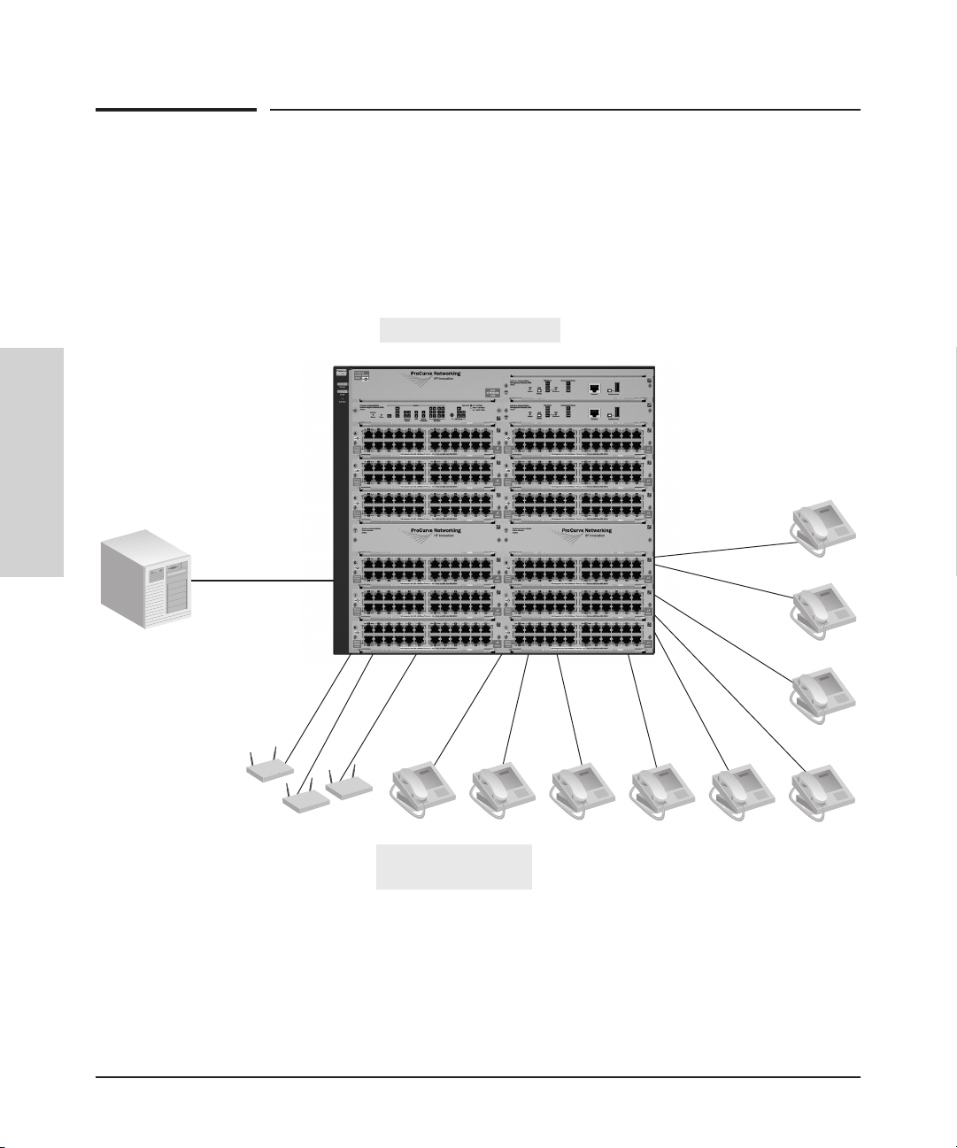
Installing the HP 8200 zl Switches
Example Network Topologies
Switches
Installing the HP 8200 zl
Example Network Topologies
This section shows a few example network topologies in which the 8200 zl
switch can be implemented.
Basic Connectivity
8212 zl Switch
2-32
Phones, APs and other
peripherals
Figure 2-16. Basic Switch Connectivity
The 8200 zl switch can provide basic network connectivity to a high number
of PoE and PoE+ devices. These devices can be easily connected, as shown
in the above illustration.
Page 64

Use as an Edge Switch
Installing the HP 8200 zl Switches
Example Network Topologies
10-Gig fiber-optic
cables
8212 zl Switch
5400 zl
Switch
Figure 2-17. Edge Switch Configuration
10-Gig fiber-optic
cables
8212 zl
Switch
Installing the HP 8200 zl
Switches
When your network expands and the users need to access resources beyond
the edge of the local network, the 8200 zl switches are excellent platforms for
that expansion. With the flexibility of 12 slots, the high port count 10/100/1000T zl Modules for local connections, and the availability of 10 Gig speeds on
both copper and fiber cables, the 8200 zl switch can provide that access
beyond the edge for a high number of network users.
In the above illustration, one 8200 zl switch, which can serve as a campus
backbone or core switch, is connected to one 5400 zl switch and one 8200 zl
switch at the edge.
The 10 Gig fiber-optic connections between the two Switches is by way of any
of the supported HP networking 10 Gig X2 transceivers installed in the
transceiver port on the 4 port 10-GbE X2 zl Module.
2-33
Page 65

Installing the HP 8200 zl Switches
Example Network Topologies
Switches
Installing the HP 8200 zl
The illustration shows the 10-gig modules in different slots. However,for best
performance, they should be mounted in one of the first six slots in case of a
single power supply running the chassis.
Optimizing the 10-GbE Port Configuration
with standard zl modules
The 10-GbE ports on the HP 8200 zl switches are designed to deliver full 10
Gbps wire-speed to each port, where either one or two ports are in a linked
state with another device. When three or four 10-GbE ports are in a linked
state, when using an X2 (J8708A), CX4 (J8707A), or SFP+ (J9308A) module,
the 10-GbE ports support an aggregate bandwidth of 28.8 Gbps across the
linked ports.
As illustrated in the figure below, internally, there are two 14.4-Gbps channels
between each of the 4 10-GbE ports and the switch fabric.
2-34
Figure 2-18. 10-GbE port architecture showing ports grouped by 14.4 Gbps channel.
When any two 10-GbE ports are in a linked state, each port automatically
operates on its own channel, which guarantees 10 Gbps of bandwidth for each
port. However, when more than two ports are in a linked state, ports A1 and
A4 are statically mapped to share one 14.4 Gbps channel, while ports A2 and
A3 are statically mapped to share the other 14.4 Gbps channel.
To summarize:
■ If only one port in a given channel is in a linked state, then that port
operates at wire speed and the other port uses no bandwidth.
■ If both ports in a given channel are in a linked state, then the 14.4 Gbps of
bandwidth is balanced fairly between the two ports.
Page 66

Installing the HP 8200 zl Switches
Example Network Topologies
For example, in an application where three ports are needed and it is important to ensure that port 1 always has a full 10 Gbps available, the connection
choices shown in the next figure would be used.
Installing the HP 8200 zl
Switches
Figure 2-19. Guaranteeing 10 Gbps on a specific port.
Optimizing the 10-GbE Port Configuration
with version 2 zl modules
The 10-GbE module (J9538A) delivers additional performance for zl switches.
There is an increase in channel throughput and port density compared to the
HP 4-Port 10-GbE CX4 zl Module (J8708A) and HP 4-Port 10-GbE X2 zl Module
(J8707A).
The 8200 zl has a fabric design that allows for optimal performance with
10-GbE v2 zl modules. When compared to the first generation zl modules, the
bandwidth channels have been improved to a maximum capacity of 23.4 Gbps
per channel, as opposed to 14.4 Gbps channels for the standard zl modules.
An eight port 10-GbE module has two 23.4 Gbps channels, for an aggregate of
46.8 Gbps of channel bandwidth. There is a fixed assignment between ports
and channel bandwidth. For an eight port 10-GbE modules, Each 23.4 Gbps
channel is allocated to 4 10-GbE ports.
2-35
Page 67

Installing the HP 8200 zl Switches
Example Network Topologies
The channel assignment is as follows:
Interfaces 1,4, 6, and 8 are assigned to channel 1. Interfaces 2, 3, 5, and 7 are
assigned to channel 2. This is demonstrated in figure 2-19.
Switches
Installing the HP 8200 zl
Ports A6 and A8
are not used
Ports A5 and A7
are not used
Figure 2-20. Version 2 optimized 10-GbE port configuration
For wire rate connectivity, do not connect more than 2 10-GbE ports to a
channel. In the diagram, it is possible to connect ports 1-4 for wire rate
connectivity because the first channel will have ports 1 and 4 connected, while
the second channel will use ports 2 and 3. If ports 1, 4, and 6 are connected,
but other ports are unused, the three ports will share up to 23.4 Gbps of
bandwidth. If ports 1, 4, 6, and 8 are connected, the ports will share 23.4 Gbps
of bandwidth between the four ports. The HP 8200 zl can support up to 4 wire
rate interfaces on an 8 port 10-GbE module (J9538A).
2-36
Page 68

Getting Started With Switch Configuration
This chapter is a guide for using the console Switch Setup screen to quickly
assign an IP (Internet Protocol) address and subnet mask to the switch, set a
Manager password, and, optionally, configure other basic features.
For more information on using the switch console and the other switch
management interfaces: the web browser interface and the SNMP management tool, ProCurve Manager, please see the HP ProCurve Management and
Configuration Guide which is on the HP Web site.
Recommended Minimal Configuration
In the factory default configuration, the switch has no IP (Internet Protocol)
address and subnet mask, and no passwords. In this state, it can be managed
only through a direct console connection. To manage the switch through inband (networked) access, you should configure the switch with an IP address
and subnet mask compatible with your network. Also, you should configure
a Manager password to control access privileges from the console and web
browser interface. Other parameters in the Switch Setup screen can be left at
their default settings or you can configure them with values you enter.
3
Getting Started With Switch
Configuration
Many other features can be configured through the switch’sconsole interface,
to optimize the switch’s performance, to enhance your control of the network
traffic, and to improve network security. Once an IP address has been configured on the switch, these features can be accessed more conveniently through
a remote TELNET session, through the switch’s web browser interface, and
from an SNMP network management station running a network management
program, such as ProCurve Manager. For a listing of switch features available
with and without an IP address, refer to “How IP Addressing Affects Switch
Operation” in the Management and Configuration Guide which is on the HP
networking Web site.
For more information on IP addressing, refer to “IP Configuration” in the
Management and Configuration Guide.
3-1
Page 69

Getting Started With Switch Configuration
Note By default, the switch is configured to acquire an IP address configuration
from a DHCP or Bootp server. To use DHCP/Bootp instead of the manual
method described in this chapter, see “DHCP/Bootp Operation” in the
Management and Configuration Guide which is on the HP networking Web
site.
Using the Switch Setup Screen
The quickest and easiest way to minimally configure the switch for management and password protection in your network is to use a direct console
connection to the switch, start a console session, and access the Switch Setup
screen.
1. Using the method described in the preceding section, connect a terminal
device to the switch and display the switch console command (CLI)
prompt (the default display).
The CLI prompt appears displaying the switch model number, for
example:
HP 8200zl#
2. At the prompt, enter the setup command to display the Switch Setup
screen. The following illustration is an example of a Setup screen with
default settings. Your screen may vary slightly.
Configuration
Getting Started With Switch
3-2
ProCurve Switch
T
imeP Mode [Disabled] : Disabled
8212zl
xl
ProCurve Switch
T
IMEP
8212zl
xl
Figure 3-1. Example Switch Setup Screen
--Mar 2007
5
Page 70

Getting Started With Switch Configuration
3. Use the Tab key to select the Manager Password field and enter a manager
password of up to 16 characters.
4. Tab to the IP Config (DHCP/Bootp) field and use the Space bar to select the
Manual option.
5. Tabto the IP Address field and enter the IP address that is compatible with
your network.
6. Tab to the Subnet Mask field and enter the subnet mask used for your
network.
7. Press Enter, then S (for Save).
The following is information on the fields in the Setup screen. For more
information on these fields, see the Management and Configuration Guide
which is on the HP Web site.
Parameter Default
System Name blank Optional; up to 255 characters, including spaces
System Contact blank Optional; up to 255 characters, including spaces
Manager Password blank Recommended; up to 16 characters (no blank spaces)
Logon Default CLI The default setting selects the command line interface for console access.
Time Zone 0 (none) Optional; 1440 to -1440. The number of minutes your location is to the
Community Name public Default setting recommended.
Spanning Tree Enabled No Default setting recommended unless STP is already running on your network
Default Gateway blank Recommended; Enter the IP address of the next-hop gateway node if network
Time Sync Method TimeP Optional; The protocol the switch uses to acquire a time signal. The options
TimeP Mode Disabled Synchronizes the time kept on the switch to the TimeP server.
IP Config DHCP/Bootp Set to Manual unless a DHCP/Bootp server is used on your network to
IP Address xxx.xxx.xxx.xxx Recommended; If you set IP Config to Manual, then enter an IP address
Note: The IP address and subnet mask assigned for the switch must be compatible with the IP addressing used in your
network. For more information on IP addressing, see the Management and Configuration Guide which is on the HP W
site.
Subnet Mask xxx.xxx.xxx.xxx Recommended; If you entered an IP address, then enter a subnet mask
The alternative is the Menu interface.
West (-) or East (+) of GMT.
or the switch will be used in complex network topologies.
traffic needs to be able to reach off-subnet destinations.
are SNTP and T
configure IP addressing.
compatible with your network.
compatible with your network.
imeP.
eb
Getting Started With Switch
Configuration
3-3
Page 71

Getting Started With Switch Configuration
Where to Go From Here
The above procedure configures your switch with a Manager password, IP
address, and subnet mask. As a result, with the proper network connections,
you can now manage the switch from a PC equipped with Telnet, a web
browser interface, or from an SNMP-based network management station
using a tool such as ProCurve Manager.
Some basic information on managing your switch is included in the next
section. For more information on the console, web browser, and SNMP
management interfaces and all the features that can be configured on the
8200zl switches, see the HP Management and Configuration Guide at
www.hp.com/networking/support.
To Recover from a Lost Manager Password:
If you cannot start a console session at the manager level because of a lost
Manager password, you can clear all passwords and user names by getting
physical access to the switch and pressing and holding the Clear button for a
full second.
Configuration
Getting Started With Switch
3-4
Page 72

Using the IP Address for Remote Switch Management
Getting Started With Switch Configuration
Using the IP Address for Remote Switch
Management
With your 8200 zl switch, you can use the switch’s IP address to manage the
switch from any PC that is on the same subnet as the switch. You can use either
a TELNET session or a standard web browser to manage the switch.
Starting a Telnet Session
To access the switch through a Telnet session, follow these steps:
1. Ensure the switch is configured with an IP address and that the switch is
reachable from the PC that is running the Telnet session (for example, by
using a ping command to the switch’s IP address).
2. Start the Telnet program on a PC that is on the same subnet as the switch
and connect to the switch’s IP address.
3. You will see the copyright page and the message “Press any key to
continue”. Press a key, and you will then see the switch console command
(CLI) prompt, for example (assuming there is no password):
HP 8200zl#
Getting Started With Switch
Enter help or ? to see a list of commands that can be executed at the
prompt. Entering any command followed by help provides more detailed
context help information about the command. Entering any command
followed by? displays a list of options that are available at that point in
the command entry.
Starting a Web Browser Session
Your 8200 zl switch can be managed through a graphical interface that you can
access from any PC or workstation on the network by running your web
browser and typing in the switch’s IP address as the URL. No additional
software installation is required to make this interface available; it is included
in the switch’s onboard software.
An example web browser interface screen is shown in the next illustration.
3-5
Configuration
Page 73

Getting Started With Switch Configuration
Using the IP Address for Remote Switch Management
Figure 3-2. Example Switch Web Browser Interface - Status Overview
Configuration
Getting Started With Switch
3-6
For more information on using the web browser interface, please see the
Management and Configuration Guide which is on the HP Web site.
An extensive help system is also available for the web browser interface. To
access the help system though, the subnet on which the switch is installed
must have access to the internet, or ProCurve Manager needs to be installed
on a network management station that is on the subnet.
Page 74

Configuring the ProCurve Wireless Edge Services zl Module (J9051A)
Getting Started With Switch Configuration
Configuring the ProCurve Wireless Edge
Services zl Module (J9051A)
Before beginning the configuration, backup the current configuration of the
switch.
The zl switch software must be updated to a version (K.12.xx) that supports
the module. Visit www.hp.com/networking/support to obtain a supported
version; to verify module support, refer to the version’s Release Notes.
The ProCurve Wireless Edge Services zl Module (J9051A) and the ProCurve
Redundant Wireless Services zl Module (J9052A) must be running software
version WT.01.xx or later.
Note: The term ‘module’ is used in this section to refer to both the ProCurve Wireless
Edge Services zl Module (J9051A) and the ProCurve Redundant Wireless
Services zl Module (J9052A).
There are four module configuration tasks required:
■ configuring an IP address for the module
■ configuring VLANs on the zl switch
■ determining a module configuration backup process
■ configuring wireless LAN services
Getting Started With Switch
Configuration
Configuring an IP Address for the Module
By default, the module uses DHCP to get an IP address. The zl switch CLI has
a command context, the wireless-services context, for configuring and managing a module.
Note ‘HP’ is used here as a generic prompt for all zl switches.
■ To identify the slot in the zl switch where the module is installed, enter
the following command:
HP# show modules
■ To show the module’s IP address, enter the following command to access
the module’s wireless-services CLI context for the module:
HP# wireless-services <slot-id>
where <slot-id> is the slot in the zl switch where the module is installed.
3-7
Page 75

Getting Started With Switch Configuration
Configuring the ProCurve Wireless Edge Services zl Module (J9051A)
■ To display the module’s IP address, enter:
HP (wireless-services-id)# show ip interfaces
The following example enters the wireless-services context of a module
installed in Slot B of a zl switch and then displays the IP address assigned by
DHCP to the module:
HP# wireless-services b
HP(wireless-services-B)#show ip interface
Interface IP-Address/Mask Status Protocol
vlan1 10.35.12.24(DHCP) up up
HP(wireless-services-B)#
If no DHCP service is available or if the administrator wishes to manually set
the Wireless Edge Services zl Module IP Address, it can be specified through
the CLI. From the wireless-services context, enter the config context and use
the interface vlan1 command to configure the vlan1 interface. Use the following
command to set the IP address:
HP(wireless-services-<slot-id>)(config-if)# ip address <IP>
where <slot-id> is the slot in the zl switch where the module is installed.
<IP> is the IP address in CIDR notation (/mask bit number), or
dhcp which will use DHCP to obtain an IP address.
Configuration
Getting Started With Switch
3-8
In the following example, the CLI commands set the module’s IP address to
10.245.22.14 with a 21-bit subnet mask.
HP(wireless-services-B)#configure
HP(wireless-services-B)(config)#interface vlan1
HP(wireless-services-B)(config-if)#ip address 10.245.22.14/21
HP(wireless-services-B)(config-if)#show ip interface
Interface IP-Address/Mask Status Protocol
vlan1 10.245.22.14/21 up up
HP(wireless-services-B)(config-if)#
If necessary,use the following command from the wireless-services andconfig
contexts to set or change the default gateway:
HP(wireless-services-B)(config)#ip default-gateway <ip-addr>
where <ip-addr> is the numeric IP address of the default gateway, for
example 10.1.2.1.
Page 76

Configuring the ProCurve Wireless Edge Services zl Module (J9051A)
Getting Started With Switch Configuration
Configuring VLANs on the zl Switch
In a wireless services-enabled zl switch, the Wireless Edge Services zl Module
and the Redundant Wireless Services zl Module use ports on the switch to pass
wired and wireless traffic to and from the network. An uplink VLAN,
containing the module’s uplink port, communicates with the wired side of the
network; downlink radio port VLANs, containing the module’s downlink port,
communicate with the wireless side of the network.
See the Wireless Edge Services zl Module Supplement to the ProCurve zl
Switch Management and Configuration Guide for detailed information to
set up and configure VLANs on the zl switch for module communications. This
manual is available at www.hp.com/networking/support.
Determining a Module Configuration Backup Process
The module’sconfiguration files are stored on the module, not on the zl switch,
unlike other zl modules. An external FTP or TFTP server must be used to back
up and restore a module’s complete configuration.
The switch does save a small subset of the module’s configuration that allows
the switch to locate the full configuration file on the external FTP or TFTP
server and to validate it using a checksum. The stored subset of a module’s
configuration file appears in a show running-config or show config command
as uneditable text.
Getting Started With Switch
For more information on configuring and managing configuration files on an
external FTP or TFTP server, see the ProCurve Wireless Edge Services zl
Modules Management and Configuration Guide, available at
www.hp.com/networking/support.
3-9
Configuration
Page 77

Getting Started With Switch Configuration
Configuring the ProCurve Wireless Edge Services zl Module (J9051A)
Configuring Wireless LAN Services
To configure wireless LAN services on a wireless services-enabled zl switch,
use one of the following management interfaces for the module:
■ Web browser interface — Accessed through a Web browser, this
intuitive interface provides comprehensive information to help you
manage and monitor your company’s wireless services. The menus
and online help guide you through configuration steps. See the
ProCurve Wireless Edge Services zl Modules Management and
Configuration Guide for information on using the Web browser
interface to configure and manage a module.
To run the Webbrowser interface for the ProCurve Wireless Edge Services
zl Module, your workstation must be running Java Virtual Machine (JVM).
If your workstation is not running the JVM and you attempt to open the
module’sWeb browser interface, the workstation will automatically try to
access the Internet and download the JVM.
■ Command line interface (CLI) — Available through a serial, Telnet,or
Secure Shell (SSH) session to the zl switch, the wireless-services
context, accessed from the zl switch’s CLI config context, provides a
complete set of commands to configure, manage, and troubleshoot
your wireless services.
Configuration
Getting Started With Switch
3-10
The CLI commands available in the wireless-services context of the zl
switch CLI are documented in an appendix of the ProCurve Wireless Edge
Services zl Modules Management and Configuration Guide. Refer to this
manual for more information.
The Web browser interface simplifies both management and configuration
tasks, and is recommended in most instances.
Page 78

4
Replacing Components
This chapter shows you how to remove and install the following components:
■ Power supplies (see page 4-2)
■ Fan tray (see page 4-5)
■ Management module (see page 4-6)
■ Management module Flash Disk (see page 4-8)
■ Replacing the Services zl Module Compact Flash Card (see page 4-9)
■ Replacing the Services zl Module Disk Drive (see page 4-10)
For a complete list of parts and part numbers, see page 2-1.
Hot Swapping The HP 8200 zl switches support “hot swapping.” Hot swapping is the ability
to replace certain hardware components while the switch is operating,
including a fan tray, power supply (if a second power supply is installed), and
certain modules.
The System Support module is not hot swappable. The Management module
and its components are not hot swappable unless there are two Management
modules installed in the switch. The Fabric modules can be hot swapped one
at a time.
The hot swapping feature allows you to remove or install modules without
powering off or rebooting the switch. Swapped-in modules are recognized by
the switch and begin functioning immediately after they are installed.
Caution The HP E8200 zl switch and its components are sensitive to static discharge.
Use an antistatic wrist strap and observe all static precautions when hot
swapping components. For example, connect your antistatic wrist strap to the
ground point on the front of the switch, above the rightmost power supply bay.
WARNING This unit may have more than one power supply cable. To fully power
down the switch, you must disconnect all power supply cables from the
unit.
4-1
Replacing Components
Page 79

Replacing Components
Replacing Power Supplies
Replacing Power Supplies
If your HP E8200 zl switch is configured with redundant power supplies, you
will not suffer any loss of traffic or performance if a power supply fails.
Replace the failed component as soon as possible. One of the Internal Power
LEDs on the management module will blink simultaneously with the switch
Fault LED indicating which power supply failed.
Caution The 8200 zl switches are designed to provide continuously operating PoE or
PoE+ power in the event of a single power supply failure with only a loss of
power to lower priority ports.
If more than one power supply fails while the switch is at or near maximum
operating power, loss of all PoE or PoE+ power may result. That is, the sum
of all PoE supply capacity minus the largest supply. (See chapter 2 and 4 of
the HP Power over Ethernet (PoE/PoE+) Planning and Implementation
Guide.)
Replacing Components
To return PoE power to the ports, without causing the switch to reboot, when
there are two or more power supplies still supplying 12V power, unplug the
power cord for 5 seconds and replug it for each power supply one at a time.
To remove an AC power supply:
1. Ensure the AC power supply is not plugged into an AC power source on
the failed power supply.
4-2
Page 80

Replacing Components
Replacing Power Supplies
2. Using either a flat-bladed or Torx T-10 screwdriver loosen the retaining
screws and remove the failed power supply.
Figure 4-1. Power Supply Removal
Replacing Components
4-3
Page 81

Replacing Components
Replacing Power Supplies
3. Insert the power supply into the opening. Slide it all the way in until it
connects to the switch. The power supply face plate will be flush with the
back face of the switch.
tighten the four screws
Replacing Components
4-4
Figure 4-2. Power Supply Installation
4. Tighten the four retaining screws that hold it in place. Be careful not to
overtighten the screws.
For more detail refer to the ProCurve Switch zl Internal Power Supply
Installation Guide (5991-3787).
Page 82

Replacing Components
Replacing Fan Trays
Replacing Fan Trays
When a fan fails the Fan Status LED on the switch chassis will blink
simultaneously with the switch Fault LED. In this case, the entire fan tray
needs to be replaced. You cannot replace individual fans.
The fan tray is hot swappable. It can be removed and replaced without
removing power from the switch. However, install the new fan tray
immediately (within two minutes) after removing the old fan tray to avoid
overheating and switch shutdown (within three minutes).
WARNING To avoid contact with spinning fans, if you are hot swapping out the
fan tray assembly, pull the assembly out one-inch and allow the fans
to stop rotating (approximately 20 seconds) before pulling it all the
way out.
To replace a fan tray:
1. Using either a flat-bladed or Torx T-10 screwdriver loosen the retaining
screws holding the fan tray assembly and pull the fan tray assembly out.
Retaining Screws
2. Install the new fan tray assembly and tighten the retaining screws.
Replacing Components
Handle
Figure 4-3. Fan Tray Removal and Installation
4-5
Page 83

Replacing Components
Replacing the Management Module
Replacing the Management Module
The Management Modules are designed to be hot-swappable, and can be
removed without damage. However, the synchronization of files may be
occurring, so to minimize the possibility of corruption between the Management Modules when one is being removed, use the “MM Shutdown” button.
Using the “MM Shutdown” button will gracefully shutdown the Management
Module, completing any synchronization of files and state information to the
second (Standby) Management Module.
Note If both Management Modules are removed from the switch at the same time,
the switch will shutdown.
If there is only one Management Module in the switch, HP networking recommends replacing the Management module, flash disk and battery (on the
Management module) during scheduled down time.
To install (or replace) a Management Module:
Replacing Components
1. On the module unscrew the retaining screws enough to disconnect them
from the threaded holes in the switch.
2. Using the extractor handles, pull the module out from the slot.
3. Remove the flash disk from the failed module and install it into the
replacement module.
4. Remove the battery from the failed module and dispose of properly.
5. Install the new battery that came with the replacement module.
6. Install the replacement module into the switch.
7. Use an equal amount of pressure and push both extractor handles closed
to completely seat the module.
4-6
Page 84

8. Tighten the retaining screws.
Replacing the Management Module
Replacing Components
Extractor Handles
Retaining Screws
Figure 4-4. Management Module Removal and Installation
4-7
Replacing Components
Page 85

Replacing Components
Replacing the Management Module Compact Flash Card
Replacing the Management Module
Compact Flash Card
The Compact Flash card is the primary non-volatile storage medium located
on the management module that contains both the boot software and
configuration files. When a Flash card fails the Flash status LED on the
management module will blink simultaneously with the switch Fault LED.
Installing a Compact Flash Card
To install (or replace) a Compact Flash card:
1. Using either a flat-bladed or Torx T-10 screwdriver loosen the retaining
screws securing the management module. (You cannot access the
Compact Flash when the management module is installed. This prevents
inadvertent removal of the system image while the system is running.)
2. Using the extractor handles, pull the management module out from the
slot.
Replacing Components
Slide out
Compact Flash
Memory disk
Figure 4-5. Management Module Flash Card Removal
3. Slide out the old flash card.
4. Slide in the new flash card being careful not to bend any pins.
5. Reinstall the management module into the switch.
6. Use an equal amount of pressure and push both extractor handles closed
to completely seat the module.
7. Tighten the retaining screws.
4-8
Page 86

Replacing the Services Module Compact Flash Card
Replacing Components
Replacing the Services Module Compact
Flash Card
The Compact Flash card is the primary non-volatile storage medium located
on the Services Module that contains both the boot software and configuration
files. When a Flash card fails the “CF Status” LED on the Services Module will
blink simultaneously with the switch Fault LED.
Installing a Compact Flash Card
To install (or replace) a Compact Flash card:
1. Using either a flat-bladed or Torx T-10 screwdriver loosen the retaining
screws securing the module. (You cannot access the Compact Flash
when the module is installed.)
2. Using the extractor handles, pull the module out of the slot and turn it over.
Slide out
Compact Flash
Memory disk
Figure 4-6. Services zl Module Flash Card Removal
3. Slide out the old flash card by applying slight pressure to the top of the
4. Position the new flash card properly and slide in the new flash card being
5. Reinstall the module into the switch.
6. Use an equal amount of pressure and push both extractor handles closed
7. Tighten the retaining screws.
Replacing Components
flash card and sliding it to the right.
careful not to bend any pins.
to completely seat the module.
4-9
Page 87

Replacing Components
Replacing the Services Module Disk Drive
Replacing the Services Module Disk Drive
The hard disk drive (HDD) is the primary storage medium located on the
Services Module. When a disk drive fails the “HDD status” LED on the Services
Module will blink simultaneously with the switch Fault LED.
Installing a Disk Drive
To install (or replace) a Disk Drive:
1. Using either a flat-bladed or Torx T-10 screwdriver loosen the retaining
screws securing the module. (You cannot access the disk drive when the
module is installed.)
2. Using the extractor handles, pull the module from the slot and turn it over.
3. Using a Cross Recess Type 1 No.1 (Phillips tip) screwdriver remove the 4
retaining screws holding the disk drive.
4. Slide the disk drive half way back to disconnect it.
5. Position the disk drive in the middle of the disk drive slot.
Replacing Components
4-10
Page 88

Replacing the Services Module Disk Drive
Replacing Components
6. Using either side of the disk drive bracket, lift the disk drive out.
Disconnected
Disk drive
retaining screws
Figure 4-7. Services zl Module Disk Drive Removal
7. Install the new disk drive and slide it forward to engage the connector.
8. Re-install the 4 retaining screws.
9. Re-install the module into the switch.
10. Use an equal amount of pressure and push both extractor handles closed
11. Tighten the retaining screws.
Lift out
to completely seat the module.
Replacing Components
4-11
Page 89

Replacing Components
Replacing the Services Module Disk Drive
Replacing Components
4-12
Page 90

Troubleshooting
This chapter describes how to troubleshoot your 8200 zl switch. Note that this
document describes troubleshooting mostly from a hardware perspective.
You can perform more in-depth troubleshooting using the software tools
available with the switch, including the full-featured console interface, the
built-in web browser interface, and ProCurve Manager, the SNMP-based
network management tool. For more information, see the chapter “Troubleshooting” in the Management and Configuration Guide, which is on the HP
networking Web site at www.hp.com/networking/support.
This chapter describes the following:
■ basic troubleshooting tips (page 5-1)
■ diagnosing with the LEDs (page 5-4)
■ Proactive networking tools (page 5-9)
■ hardware diagnostic tests (page 5-10)
■ restoring the factory default configuration (page 5-13)
■ downloading new code (page 5-14)
■ HP Customer Support Services (page 5-14)
5
Troubleshooting
Basic Troubleshooting Tips
Most problems are caused by the following situations. Check for these items
first when starting your troubleshooting:
■ Faulty or loose cables. Look for loose or obviously faulty connections.
If they appear to be OK, make sure the connections are snug. If that does
not correct the problem, try a different cable.
■ Non-standard cables. Non-standard and miswired cables may cause
network collisions and other network problems, and can seriously impair
network performance. Use a new correctly-wired cable or compare your
cable to the cable in appendix B, “Switch Ports and Network Cables” for
pinouts and correct cable wiring. A category 5 cable tester is a recommended tool for every 100Base-TX and 1000Base-T network installation.
5-1
Page 91

Troubleshooting
Basic Troubleshooting Tips
Troubleshooting
■ Improper Network Topologies. It is important to make sure you have
a valid network topology. Common topology faults include excessive
cablelength and excessive repeater delays between end nodes. If youhave
network problems after recent changes to the network, change back to
the previous topology. If you no longer experience the problems, the new
topology is probably at fault.
In addition, you should make sure that your network topology contains
no data path loops. Between any two end nodes, there should be only
one active cabling path at any time. Data path loops will cause broadcast
storms that will severely impact your network performance.
With your 8200 zl switch, if you wish to build redundant paths between
important nodes in your network to provide some fault tolerance, you
should enable Spanning Tree Protocol support on the switch. This
ensures that only one of the redundant paths is active at any time, thus
avoiding data path loops. Spanning Tree can be enabled through the
switch console, the Web browser interface, or ProCurve Manager.
The 8200 zl switch also supports Trunking, which allows multiple
network cables to be used for a single network connection without
causing a data path loop. See the Management and Configuration Guide
for more information on Spanning Tree and on Trunking, which is on the
HP Web site.
5-2
■ Connecting to devices that have a fixed full-duplex configuration.
The RJ-45 ports on the 8200 zl switch are configured as “Auto.” That is,
when connecting to attached devices, the switch will operate in one of
two ways to determine the link speed and the communication mode (half
duplex or full duplex):
• if the connected device is also configured to Auto, the switch will
automatically negotiate both link speed and communication mode
• if the connected device has a fixed configuration, for example 100
Mbps, at half or full duplex, the switch will automatically sense the
link speed, but will default to a communication of half duplex
Because the 8200 zl switch behaves in this way (in compliance with the
IEEE 802.3 standard), if a device connected to the switch has a fixed
configuration at full duplex, the device will not connect correctly to the
switch. The result will be high error rates and very inefficient communications between the switch and the device.
Ensure that all devices connected to the 8200 zl switch are configured to
auto negotiate, or are configured to connect at half duplex (all hubs are
configured this way, for example).
Page 92

Basic Troubleshooting Tips
Troubleshooting
If necessary though, you can modify the configuration of the ports on the
8200 zl switch to match the configuration of the connected device. Use
the switch console, the Web browser interface, or ProCurve Manager to
modify the port configuration.
■ Check the port configuration. A port on your 8200 zl switch may not
be operating as you expect because it has been put into a “blocking” state
by Spanning Tree, GVRP (automatic VLANs), or LACP (automatic
trunking). (Note that the normal operation of the Spanning Tree, GVRP,
and LACP features may put the port in a blocking state.) Or, the port just
may have been configured as disabled through software.
Use the switch console to determine the port’s configuration and verify
that there is not an improper or undesired configuration of any of the
switch features that may be affecting the port. See the Management and
Configuration Guide which is on the HP networking Web site.
For more information on possible network problems and their solutions, refer
to the technical note “Troubleshooting LAN Performance and Intermittent
Connectivity Problems”, which can be found on the HP networking Web site
in the Reference Library, www.hp.com/networking/support, in the A-Z index
section.
Troubleshooting
5-3
Page 93

Troubleshooting
Diagnosing with the LEDs
Troubleshooting
Diagnosing with the LEDs
Table 5-1 shows LED patterns on the switch and the switch modules that
indicate problem conditions.
1. Check in the table for the LED pattern you see on your switch
2. Refer to the corresponding diagnostic tip on the next few pages.
Table 5-1.
Power
Off with
power cord
plugged in
On Prolonged OnProlonged
On Blinking
On Blinking
On Blinking
On Off Off Blinking
On Blinking
On Blinking
On Blinking
On Off Off Off
On Off Off On
1
This LED is not important for the diagnosis.
2
The blinking behavior is an on/off cycle once every 1.6 seconds, approximately.
3
The fast blinking behavior is an on/off cycle once every 0.8 seconds, approximately
Fault
1 1 1 1 1 1
LED Error Indicators
LED Pattern Indicating Problems
Test
(one LED per
Module Status
1 1 1 1
On
2
2
2
2
2
2
2
Blinking
Blinking2Blinking
Blinking2Blinking
Blinking2Blinking
Off
Off
Off
1
1 1
module)
2
2
2
2
Power
(one LED per
power supply)
1 1 1
1 1
1 1
1 1 1
1 1
†
Blinking
1 1
1 1
Fan
*
Blinking
†
Port Link
Never On
On briefly,
then Off
2
Blinking
1
1
Fast blinking
Off with cable
connected
Diagnostic
3
Tips
➊
➋
➌
➍
➎
➏
➐
➑
➒
➓
l
11
5-4
Page 94

Diagnostic Tips:
Diagnosing with the LEDs
Troubleshooting
Tip
Number
➊
➋
➌
Problem Solution
The power supplies
installed in the
switch are not
plugged into active
AC power sources,
or the power supply
may have failed.
A switch hardware
failure has
occurred. All the
LEDs will stay on
indefinitely.
The switch has
experienced a
backplane failure
during self test.
1. Verify the power cord is plugged into an active power source and to the switch.
Ensure these connections are snug.
2. Try power cycling the switch by unplugging and plugging the power cord back in.
3. If the Power LED is still not on, verify the AC power source works by plugging
another device into the outlet. Or try plugging the switch into a different outlet or
try a different power cord.
If the power source and power cord are OK and this condition persists, the switch
power supply may have failed. Call your HP authorized dealer
support services from HP to get assistance. See the Customer Support/Warranty
card for more information.
Try power cycling the switch. If the fault indication reoccurs, the switch may have
failed. Call your HP authorized dealer, or use the electronic support services from
HP to get assistance. See the Customer Support/Warranty card for more
information.
The failure may be just in the communications with a single module slot, or it might
be more significant. Start a console session with the switch, and at the CLI prompt
issue the command show logging. In the event log that is displayed, there will be
messages that describe the extent of the problem. If the problem is with individual
slots, the remainder of the switch slots will be fully operational and can be used until
you get a chance to replace the switch.
If necessary to resolve the problem, contact your HP authorized dealer, or use the
electronic support services from HP to get assistance. See the Customer Support/
W
arranty card for more information.
Troubleshooting
, or use the electronic
➍
The module
installed in the slot
that corresponds to
the letter that is
blinking is an
invalid module.
The fact that the Link and Mode LEDs never are lit on the module indicates that it is
a Switch gl module and should not be used in your zl switch.
Ensure you have installed a zl module in the slot. xl/gl modules will fit in
the slot, but they are not compatible with your zl switch. Check to ensure
the module has a Blue
Remove the module from the switch and replace it with a zl module, or
recover the slot with the cover plate. Y
without having to power down the switch. Call your HP authorized dealer, or use the
electronic support services from HP to get information on supported Switch zl
modules. The modules that are available as of the printing of this manual are listed
on page 1-17.
“zl module” symbol on it.
ou can remove and replace the module
5-5
Page 95

Troubleshooting
Diagnosing with the LEDs
Tip
Number
Problem Solution
➎
Troubleshooting
The module
installed in the slot
that corresponds to
the letter that is
blinking has
experienced a self
test or initialization
fault.
The modules are all tested whenever the switch is powered on, or reset (through
the Reset button on the switch, or the Boot or Reset options in the console or web
browser interface), and when they are hot swapped (installed when the switch is
powered on).
Since the Link and Mode LEDs on the module were lit at least briefly, that indicates
that the module did receive power from the switch, but the subsequent download
process failed. Either the module is faulty, or it is a new module type that is not yet
supported by the operating code on the switch.
As HP networking introduces new modunes for your HP Switch zl, you may have to
update the switch with new operating code that supports the new module. The
documentation that came with the module will indicate which version of the
operating code is needed to support the module. The modules that are supported in
your Switch zl, as of the printing of this manual, are listed on
Features”. The latest code can be downloaded from the HP networking Web site at
www.hp.com/networking/support.
First verify the switch has a version of code that supports the module that is
indicating the fault. If the module is not one of the ones listed on
the module documentation to see what version of switch code is needed. Download
the new code and retest the module.
If you have the correct code installed in the switch, try removing and reinstalling the
module. You can do this without having to power down the switch. When the module
is reinstalled, it will be retested automatically.
If the fault indication reoccurs, the module may have failed. Remove the module from
the switch and replace it with a known good module, or install the failed module into
an empty slot and retest it. If you remove the module always recover the slot with
the cover plate. Call your HP authorized dealer, or use the electronic support
services from HP to get assistance. See the Customer Support/Warranty card for
more information.
page 1-17 under “Switch
page 1-17, check
5-6
➏
In the slot
corresponding to
the letter that is
blinking, a module
was installed that is
a different type
than the previously
installed module,
and the switch has
not yet been reset.
When you “hot swap” modules in the switch slots, if you install a different module
type than the one that was previously installed in the slot, you must reset the switch
so the switch processor can properly initialize and configure the new module type.
The blinking LED informs you that this change of module types has occurred. The
module will not work properly until the switch is reset.
You can reset the switch by any of these methods:
• pressing the Reset button.
• power cycling the switch.
• selecting the reset or reboot option from the console, web browser interface, or
ProCurve Manager.
Page 96

Tip
Number
➐
Problem Solution
The network port
for which the Link
LED is blinking has
experienced a self
test or initialization
failure.
During the module self test, described in tip number 4 earlier in this table, each
network port is also tested. If the port self test fails, the individual port is not usable,
but the rest of the ports on the module, which have passed their self test, will
continue to operate normally.
If the port is a transceiver, verify it is one of the transceivers supported by the
mini-GBIC zl Module. Unsupported transceivers will be identified with this fault
condition. The supported transceivers are listed in the module Installation Guide.
The transceivers are also tested when they are “hot-swapped”--installed or
changed after the mini-GBIC zl Module is installed and receiving power from the
switch.
To verify the port has failed, try removing and reinstalling the module, as described
in tip number 4. For the transceivers, you can just remove and reinstall the
transceiver without having to remove the module. If the port fault indication
reoccurs, and you need to be able to use the port, you will have to replace the
transceiver or the module. In the mean time, all the other module ports will operate
normally.
Diagnosing with the LEDs
Troubleshooting
Troubleshooting
➑
➒
➓
A fault condition
has been detected
on the power
supply installed in
the slot
corresponding to
the blinking
number.
One or more of the
switch cooling fans
may have failed.
The network port
for which the Link
LED is blinking has
been disabled
because port
security has been
configured on the
switch and a
security violation
has been detected
on the port.
Try removing and reinstalling the power supply.
Caution: Ensure the AC power cord is disconnected from the supply before removing
and reinstalling the supply.
Reconnect the power supply to the AC power source. If the error indication reoccurs
after the supply is reinstalled, the power supply may be faulty. Call your HP
authorized dealer, or use the electronic support services from HP networking to get
assistance. See the Customer Support/Warranty card for more information.
Try disconnecting power from the switch and wait a few moments. Then reconnect
the power to the switch and check the LEDs again. If the error indication reoccurs,
one or more of the fans has failed. The switch has multiple fans and may continue
to operate OK under this condition if the ambient temperature does not exceed
normal room temperature, but for best operation, the fan tray should be replaced.
Contact your HP authorized dealer, or use the electronic support services from HP
networking to get assistance. See the Customer Support/Warranty card for more
information.
For the Port Security feature, you can configure the switch so that whenever a
security violation is detected on a port, the switch will disable the port. When a port
is disabled by this feature, the port Link LED will be continuously flashed at the fast
rate of 0.8 seconds per cycle. The blinking continues until you clear the security
violation through the switch console. In the console, you can view the identity of the
connected device that committed the security violation.
Once the security violation is cleared, you must re-enable the port through the
console.
For more information on the Port Security feature, see the Management and
Configuration Guide which is on the HP Web site.
5-7
Page 97

Troubleshooting
Diagnosing with the LEDs
Tip
Number
Problem Solution
Troubleshooting
The network
l
connection is not
working properly.
Try the following procedures:
• For the indicated port, verify both ends of the cabling, at the switch and the
connected device, are securely connected.
• Verify the connected device and switch are both powered on and operating
correctly
• Verify you have used the correct cable type for the connection.
– for any of the twisted-pair connections, in the default configuration (Auto),
– for fiber-optic connections, verify that the transmit port on the switch is
• For a 1000 Mbps connection, verify the network cabling complies with the IEEE
802.3ab standard. The cable should be installed according to the ANSI/TIA/EIA568-A-5 specifications. Cable testing should comply with the stated limitations
for Attenuation, Near
Crosstalk (ELFEXT), Multiple Disturber ELFEXT, and Return Loss.
The cable verification must include all patch cables from any end devices,
including the switch, to any patch panels in the cabling path.
• Verify the port has not been disabled through a switch configuration change.
You can use the console interface, or, if you have configured an IP address on
the switch, use the web browser interface, or ProCurve Manager network
management software to determine the state of the port and re-enable the port
if necessary
• Verify the switch port configuration matches the configuration of the attached
device. For example, if the switch port is configured as “Auto”, the port on the
attached device also MUST be configured as “Auto”. Depending on the port type,
twisted-pair or fiber
a very unreliable connection, or no link at all.
If the other procedures don’t resolve the problem, try using a different port or a
different cable.
.
either a straight-through or a crossover cable can be used and the switch will
automatically adjust its operation. See the “HP Auto-MDIX Feature”
description on page B-7 for more information.
Note: If the module configuration is changed to one of the fixed
configuration options though (for example, 100-Full Duplex), then the port
operates as MDI-X only and the correct type of cable must be used. in
general, for connecting to an end node (MDI port), use straight-through
cable; for connecting to MDI-X ports on hubs, other switches, and routers,
use crossover cable.
connected to the receive port on the connected device, and the switch
receive port is connected to the transmit port on the connected device, and
that both devices are transmitting correctly
-End Crosstalk, Far-End Crosstalk, Equal-Level Far-End
.
-optic, if the configurations don’t match, the results could be
.
5-8
Page 98

Troubleshooting
Proactive networking
Proactive networking
The 8200 zl switch has built-in management capabilities that proactively help
you manage your network including:
■ finding and helping you fix the most common network error conditions
(for example, faulty network cabling, and non-standard network
topologies)
■ informing you of the problem with clear, easy-to-understand messages
■ recommending network configuration changes to enhance the
performance of your network
The following interfaces provide tests, indicators, and an event log that can
be used to monitor the switch and its network connections, and to help you
take advantage of these proactive networking features:
■ ProCurve Manager - an SNMP-based network management tool included
with your switch
■ A graphical web browser interface you can use to manage your switch
from a PC that is running a supported web browser,for example Microsoft
Internet Explorer or Netscape Communicator.
■ A full-featured easy-to-use console interface you can access by merely
connecting a standard terminal or PC running a terminal emulator to the
switch’sconsole port. The cable to make that connection is provided with
your switch. The console interface is also accessible through a telnet
connection.
Troubleshooting
See the “Troubleshooting” chapter in the Management and Configuration
Guide for more information on using these software tools to diagnose and
manage your switch, which is on the HP Web site.
5-9
Page 99

Troubleshooting
Hardware Diagnostic Tests
Troubleshooting
Note When a module is exchanged for a different type, until the switch is reset
Hardware Diagnostic Tests
Reasons for Resetting the Switch
Generally, you only need to reset the switch when it needs to recognize a
change in its hardware or software (console) configuration. Some
circumstances in which you will need to reset the switch are:
■ Installing a module in a slot that was previously occupied by a different
type of module, the switch must be reset after the new module is installed
so the switch processor can properly initialize and configure the new
module type.
the module will not operate, the Module Status LED (orange) for the slot
will blink, the chassis fault LED will blink simultaneously,and all the LEDs
on the module will stay on continuously.
■ Changing certain switch configuration parameters through the console
interface. (In this case, the console provides indications when the switch
must be reset for the configuration change to be activated.)
5-10
You do not need to reset the switch when:
■ Installing a module in a previously unused slot.
■ Replacing a module with the same type of module.
Methods of Resetting the Switch
You can reset the switch by any of these methods:
■ pressing the Reset button. On the 8212 zl or 8206 zl switch, this is the
System Reset button on the System Support module.
■ power cycling the switch (if both power supplies are being used, you will
have to disconnect both power cords)
■ issuing the boot command from the switch console CLI, or selecting the
Reset or Boot option from the switch console menu, Web browser inter-
face, or ProCurve Manager
Page 100

Testing the Switch by Resetting It
Hardware Diagnostic Tests
Troubleshooting
If you believe the switch is not operating correctly, you can reset the switch
to test its circuitry and operating code. To reset a switch, either:
■ Unplug and plug in the power cord (power cycling)
■ Press the Reset button on the System Support module
■ Select the reset or reboot option from the console, web browser interface,
or ProCurve Manager.
Power cycling the switch, pressing the Reset button on the System Support
module, and the software reset or reboot options all cause the switch to
perform its power-on self-test, which almost always will resolve any temporary operational problems. These reset processes also cause any network
traffic counters to be reset to zero and cause the System Up Time timer to
reset to zero. Neither of these reset procedures causes any changes to the
switch configuration.
Checking the Switch LEDs
The self-test passes if the Fault and Test LEDs on the front of the switch go
off after approximately 90 to 150 seconds depending on the number and type
of modules installed in the switch. If these LEDs stay on longer than 180
seconds or begin blinking, the switch, or a module, or an individual transceiver
may have to be replaced as indicated by the LEDs.
See “Diagnosing With the LEDs” on page 5-4 for information on interpreting
the LED patterns.
Troubleshooting
Checking Console Messages
Useful diagnostic messages may be displayed on the console screen when the
switch is reset. As described in chapter 2 under step 8, “Connect a Console to
the Switch”, connect a PC running a VT-100 terminal emulator program or a
standard VT-100 terminal to the switch’s Console Port and configure it to run
at 9600 baud and with the other terminal communication settings shown on
page 2-27. Then, when you reset the switch, note the messages that are
displayed.
5-11
 Loading...