

Page 1
Illustrated Parts & Service Map
HP Compaq dx7510/dx7518 Business PC
Microtower Chassis
© 2009 Hewlett-Packard Development Company, L.P. The information con-
tained herein is subject to change without noti ce. HP shall not be liable for
technical or editorial errors or omissions contained herein. Intel, Pentium,
Intel Inside, and the Intel logo are trademarks or registered trademarks of the
Intel Corporation and its subsidiaries in the U. S. and other countries.
Document Number 516948-001. 1st Edition April 2009.
Key Specifications
Processor Type Intel Celeron, Pentium Dual-Core, Core2 Duo, Core2 Quad
RAM Type DDR3-SDRAM DIMMs, PC3-10600 (1333 MHz) non-ECC
Maximum RAM Supported 8 GB, 4 slots
Expansion Slots • 1 PCIe-x1 (full height)
Graphics Adapter Intel Graphics Media Accelerator GMA4500
Drive Support • 2 hard disk drives
Bays • 2 external 5.25-inch
I/O Interfaces PS/2 (keyboard & mouse), VGA, parallel, port, serial port, line
Spare Parts
• 1 PCIe-x16 for graphics cards (full height)
• 2 PCI slots (full height)
• 2 optical disk drives
• floppy diskette drive, media card reader
• 1 external 3.5-inch
• 2 internal 3.5-inch
in, line out, mic in, RJ-45, USB 2.0 (8 external, 3 internal)
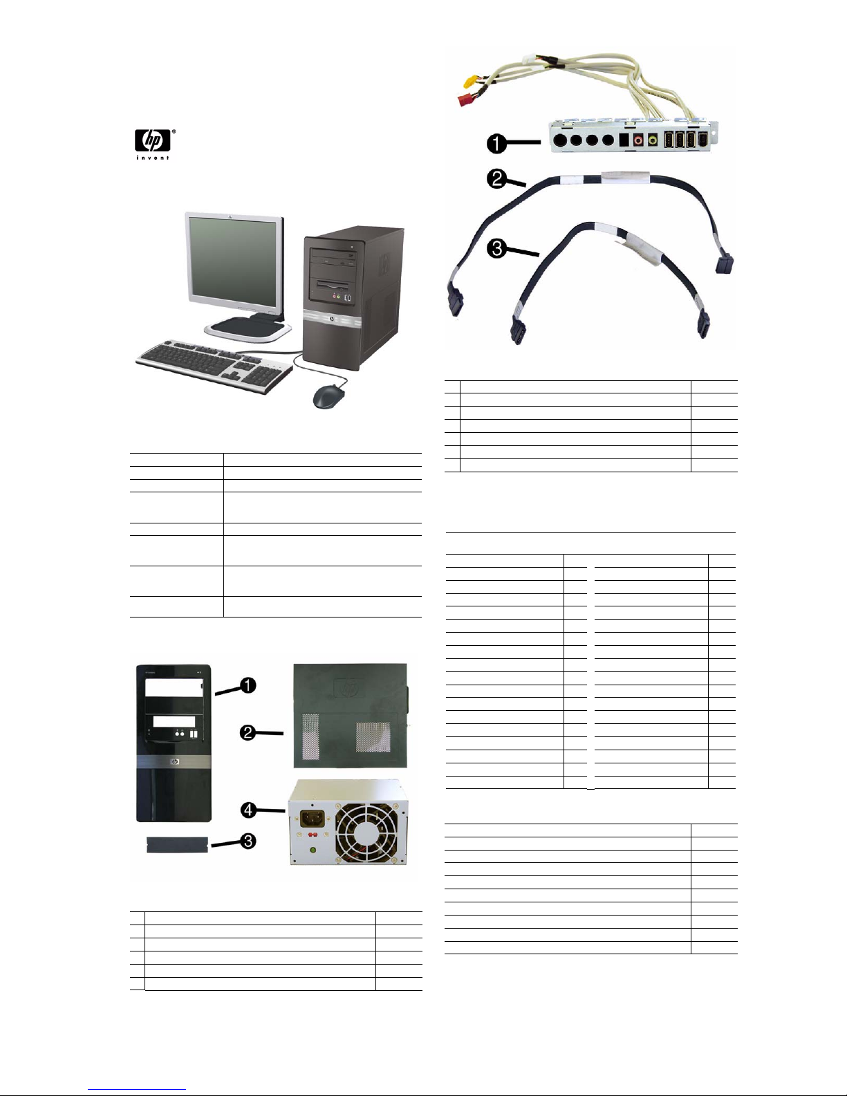
Cables
1 Front I/O, 3 USB, audio 514235-001
2 SATAII hard drive cable, 3Gb/s, 180 mm (7 inch) 530595-001
3 SATAII optical drive cable, 3Gb/s, 180 mm (7 inch) 530594-001
* Power switch/LED assembly 530592-001
* IDE cable, 200-mm (7.9-inch) 530596-001
* DVI cable 484156-001
* HP DisplayPort To DVI-D Adapter (for HD3470 and HD3650) 202997-001
*Not shown
Keyboards (not illustrated)
PS/2, Basic
USB, Basic
Arabic -171 LA Spanish -161
Belgian -181 Norwegian -091
BHCSY -B41
Brazilian Portuguese -201 Portuguese -131
Bulgarian -261 Romanian -271
Czech -221 Russian -251
Danish -081
Finnish -351 Slovakian -231
French -051 South Korea -KD1
French Canadian -121
German -041 Swedish -101
Greek -151 Swiss -111
Hebrew -BB1 Taiwanese -AB1
Hungarian -211 Thai -281
International -B31
International English -L31
Italian -061 U.K. -031
Japanese -291
435302-xxx
435382-xxx
People’s Republic of China
Saudi Arabia -DE1
Spanish -071
Turkish -141
U.S. -001
-AA1
System Unit
1 Front bezel, dx7510 514233-001
* Front bezel, dx7518 514234-001
2 Access panel 530591-001
3 5.25-inch bezel blank 335937-001
* 3.5-inch bezel blank 459913-001
4 Power supply, 300W, PFC 514232-001
dx7510/dx7518 Illustrated Parts & Service Map, MT chassis 516948-001 page 1
Mass Storage Devices (not illustrated)
Diskette drive with bezel 431452-001
16X SATA SuperMulti DVD±RW and CD-RW drive with LightScribe 447310-001
16X SATA DVD±RW and CD-RW drive with LightScribe 419498-001
16X SATA DVD-ROM drive 419496-001
CD-RW Combo drive 419497-001
500 GB, 7200-RPM SATA hard drive, 3.5-inch 457909-001
320 GB, 7200-RPM SATA hard drive, 3.5-inch 497731-001
250 GB, 7200-RPM SATA hard drive, 3.5-inch 449980-001
160 GB, 10000-RPM SATA hard drive, 2.5-inch with adapter 449979-001
80 GB, 7200-RPM SATA hard drive, 3.5-inch 449978-001
Page 2
Standard and Optional Boards
1 System board, includes thermal material 514237-001
Memory modules (PC2-6400, CL5)
* 1 GB (PC3-10600)
* 2 GB (PC3-10600)
Other boards
* HP Wireless 802.11b/g/n PCIe card, for use world-wide, includes full
height bracket
* LSI PCIe x1 56K International SoftModem, includes bracket 490689-001
* ATI Radeon HD 2400XT 256MB Dual Head graphics adapter (PCIe x16),
low profile with ATX bracket
* ATI Radeon HD 3450 (256MB) PCIe x16 card 491168-001
* ATI Radeon HD 3650 512MB Dual Head graphics adapter (PCIe x16),
includes bracket
* Intel Pro 1000 PT Gb Ethernet PCIe NIC, includes bracket 490 367-001
* 3-port 1394 PCI card, FH 441448-001
* Nvidia Quadro4 380 XGL 64-MB graphics adapter 311507-001
Intel Celeron Processors with alcohol pad and thermal grease
* E1400, 2.0 GHz, 512-KB L2 cache, dual core 491574-001
* E1200, 1.6 GHz, 512-KB L2 cache, dual core 468589-001
* 450, 2.2 GHz, 512-KB L2 cache 508256-001
* 440, 2.0 GHz, 512-KB L2 cache 449166-001
* 430, 1.8 GHz, 512-KB L2 cache 449165-001
Intel Pentium Dual Core Processors with alcohol pad and thermal grease
* E5200, 2.5 GHz, 2-MB L2 cache 503382-001
* E2200, 2.2 GHz, 1-MB L2 cache 465216-001
Intel Core 2 Quad Processors with alcohol pad and thermal grease
* Q9650, 3.00 GHz, 12-MB L2 cache 497734-001
* Q9550, 2.83 GHz, 12-MB L2 cache 465758-001
* Q9400, 2.66 GHz, 6-MB L2 cache 497733-001
* Q8200, 2.33 GHz, 4-MB L2 cache 503381-001
* Q6600, 2.4 GHz, 8-MB L2 cache 452451-001
Intel Core 2 Duo Processors with alcohol pad and thermal grease
* E8600, 3.33 GHz, 6-MB L2 cache 497 732-001
* E8500, 3.16 GHz, 6-MB L2 cache 466 170-001
* E8400, 3.00 GHz, 6-MB L2 cache 509 554-001
* E7400, 2.80 GHz, 3-MB L2 cache 508 255-001
* E7300, 2.66 GHz, 3-MB L2 cache 500 134-001
* Not shown
576109-001
576110-001
498307-001
462477-001
481421-001
Miscellaneous Parts
1 Internal speaker, 40mm x 28mm 480733-001
2 Fansink with alcohol pad and factory-applied thermal grease 514236-001
3 Chassis fan 514238-001
*
22-in-1 media card reader, 3.5-inch, includes 5.25-inch conversion kit 480033-001
* Mouse, PS2, optical 417966-001
* Mouse, optical 390938-001
* Mouse, laser 459821-001
* Modem cable 198220-005
* Second serial port 530599-001
* Rear I/O cover assembly 530849-001
* Hood sensor 393603-001
* HP Thin USB powered speakers 466618-001
*Not shown
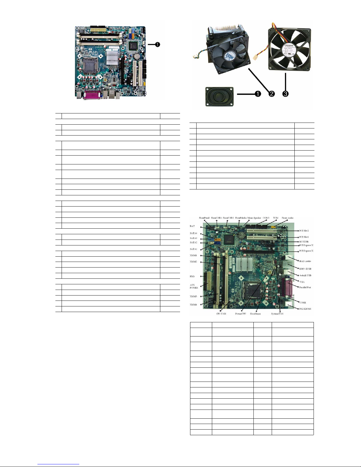
System Board
System Board Connectors and Jumpers (component location may vary)
F_PANEL Front panel connector COM1 COM1
F_USB1 Front USB connector PS2 KS/MSKeyboard and mouse PS2
F_USB2 Front USB connector
MEDIA Front media connector HOOD-
SPEAKER Speaker connector ATX_12V CPU power connector
COM2 COM2 CPU_FAN CPU/heatsink fan connector
TCM TCM connector XMM3 Memory socket 3
F_AUDIO Front audio connector XMM4 Memory socket 4
PCI1 PCI Slot 1 ATX_
PCI2 PCI Slot 2 FLOPPY Diskette drive connector
Buzzer Buzzer XMM1 Memory socket 1
PCI E(X1) PCI Express X1 XMM2 Memory socket 2
PCI E(X16) PCI Express X16 SATA1 Primary SATA hard drive
AUDIO HAD audio SATA2 1st SATA optical drive
LAN+USB Stacked RJ-45/Double USB
USB 4 stack USB connectors SATA4 2nd SATA optical drive
VGA VGA connector BAT RTC battery socket
PARALLEL Parallel port
connectors
SYS_FAN1
SENSE
POWER
SATA3 2nd SATA hard drive
connectors
System fan connector
Hood sensor connector
Main power connector
dx7510/dx7518 Illustrated Parts & Service Map, MT chassis 516948-001 page 2
Page 3

POST Front Panel LEDs and Audible Codes
Beeps/Activity Possible Cause Recommended Action
0 Beeps
Green Power LED On
0 Beeps
Green Power LED flashes
every two seconds
2 Beeps
CPU fan is weak (RPM <
1000) or not turning. A
warning message is displayed along with a series of
long beeps for five seconds,
then the system shuts down
5 Beeps
Red Power LED flashes five
times, once every second,
followed by a two second
pause. Beeps stop after fifth
iteration but LEDs continue
until problem is solved
6 Beeps
Red Power LED flashes six
times, once every second,
followed by a two second
pause. Beeps stop after fifth
iteration but LEDs continue
until problem is solved
8 Beeps
Red Power LED flashes
eight times, once every second, followed by a two second pause. Beeps stop after
fifth iteration but LEDs continue until problem is solved
0 Beeps
System does not power on
and LEDs are not flashing
Computer on None
Computer in Suspend to RAM mode
(some models only)
or normal Suspend
mode.
Processor thermal
protection activated:
A fan may be
blocked or not turning.
OR
The heatsink/fan
assembly is not
properly attached to
the processor.
Pre-video memory
error.
Pre-video graphics
error.
System board failure or invalid ROM
based on bad checksum.
System unable to
power on.
For systems with a graphics card:
1. Reseat the graphics card. Power on
2. Replace the graphics card.
3. Replace the system board.
For systems with integrated graphics,
replace the system board.
1. Ensure that the computer air vents
2. Open hood, press power button, and
3. If fan is plugged in and seated prop-
4. Reseat processor heatsink and verify
5. Contact an authorized reseller or
CAUTION: To avoid damage to the
DIMMs or the system board, you must
unplug the computer power cord
before attempting to reseat, install, or
remove a DIMM module.
1. Reseat DIMMs.
2. Replace DIMMs one at a time to
3. Replace third-party memory with
4. Replace the system board.
For systems with a graphics card:
1. Reseat the graphics card.
2. Replace the graphics card.
3. Replace the system board.
For systems with integrated graphic s,
replace the system board.
1. Reflash the system ROM with the
2. Replace the system board.
Press and hold the power button for
less than 4 seconds. If the hard drive
LED turns green, the power button is
working correctly. Try the following:
1. Check that the voltage selector
2. Replace the system board.
Press and hold the power button for
less than 4 seconds. If the hard drive
LED does not turn on green then:
1. Check that the unit is plugged into a
2. Open hood and check that the power
3. Check that both power supply
the system.
are not blocked and the processor
cooling fan is running.
see if the processor fan spins. If the
processor fan is not spinning, make
sure the fan's cable is plugged onto
the system board header. Ensure the
fan is fully/properly seated and
installed.
erly, but is not spinning, then
replace processor fan.
that the fan assembly is properly
attached.
service provider.
isolate the faulty module.
HP memory.
latest BIOS image.
(some models), located on the rear
of the power supply, is set to the
appropriate voltage. Proper voltage
setting depends on your region.
OR
working AC outlet.
button harness is properly connected
to the system board.
cables are properly connected to the
system board.
System Setup and Boot
Basic system information regarding system information, setup, power management, hardware,
and passwords is maintained in the Setup Utility held in the system ROM. The Setup Utility is
accessed by pressing the F10 key when prompted (on screen) to do so during the boot sequence.
If the screen prompt opportunity is missed, a restart is necessary. For more information about
Setup Utilities refer to the Service Reference Guid e..
Computer Setup Menu
Heading Option / Description
System
System S/N (view only)
Information
Product Name (view only)
Ownership Tag Enter ownership tag assigned by the owner.
BIOS Version (view only)
BIOS Release Date (view only)
System Chipset Type (view only)
Processor Type (view only)
Processor Speed (view only)
CPU ID (view only)
Cache Size (view only)
Memory DIMM1 (view only)
Memory DIMM2 (view only)
Memory DIMM3 (view only)
Memory DIMM4 (view only)
Computer Setup Menu (continued)
Heading Option / Description
DDR Memory Size (view only)
UUID (view only)
Chassis Serial Number
Asset Tag Number Enter asset tag number assigned by the company.
Integrated MAC (view only)
Standard
Date (mm:dd:yy: Allows you to set system date.
CMOS
Features
Time (hh:mm:ss) Allows you to set system time.
Floppy Drive A Allows you to set Drive A of None or 1.44M, 3.5 inch.
SATA Port 0
SATA Port 1
SATA Port 2
SATA Port 3
SATA Mode Allows you to set the SATA mode to:
Legacy Mode Support Disables/enables legacy mode support.
Halt On Allows you to set POST error behavior to:
Advanced
F11 Prompt Setting this feature to displayed will display the text F11
BIOS Features
Quick Power On Self
Tes t
POST Delay Time Allows you to set a POST delay time to:
Hard Drive Boot Pri-
ority
CD-ROM Boot Prior-
ity
Network Group Boot
Priority
First Boot Device
Second Boot Device
Third Boot Device
Fourth Boot Device
Boot Other Device Disables/enables boot other device.
Load Boot Menu
Selectable
APIC Mode Disables/enables the Advanced-PIC mode.
System Keyboard Allows you to set the system keyboard to Absent or
Boot Up NumLock
Status
Security Option Allows you to set the security option to Setup or System
HDD S.M.A.R.T.
Capability
Advanced
On-Chip Frame
Chipset
Buffer Size
Features
(VGA Setting)
PEG/Onchip VGA
Control
DVMT Mode
(VGA Setting)
DVMT/FIXED Mem-
ory Size
(VGA Setting)
Init Display First
(VGA Setting)
(view only)
For each, allows you to:
• detect HDD size and head on selected channel
• set extended drive on selected channel to:
- None
- Auto
- Manual
• set access mode on selected channel to:
- CHS
- LBA
- Large
- Auto
•view:
- Capacity
- Cylinder
- Head
- Precomp
- Landing Zone
- Sector
• SMART Support
- SMART Status Check
- SMART Short Self-Test
- SMART Extended Self-Test
•IDE
• AHCI
• All Errors
• No Errors
• All but Keyboard
• All but Diskette
• All but Diskette/Keyboard
= Recovery during POST. Hiding this feature prevents
the text from being displayed. However, pressing F11
will still attempt to boot to the HP Backup and Recovery
partition.
Disables/enables the system to skip certain tests while
booting.
Enabling this feature decreases the time required to boot
the system.
• None
• 5 Seconds
• 10 Seconds
• 15 Seconds
• 20 Seconds
Specifies boot device priority within hard drives.
Specifies boot device priority within CD/DVD drives.
Specifies boot device priority within bootable network
devices.
Allows you to specify which device groups will boot
first, second, third, and fourth or to disable any
of the four:
•Removable
•Hard Disk
• CDROM
•Network
•Disabled
NOTE: MS-DOS drive lettering assignments maybe
apply after a non-MS-DOS operating system has started.
Disables/enables boot menu selectable.
Present.
Allows you to set the default NumLock status to off or
on.
so that the password is required every time the system
boots or only when entering Computer Setup.
Disables/enables hard drive S.M.A.R.T. capability.
Select the On-Chip Frame Buffer Size to:
•32MB
•64MB
•128MB
Allows you to set VGA control to:
• Onchip VGA
• PEG port
• Auto
Disables/enables DVMT mode.
Allows you to set memory size to:
•128MB
•256MB
Allows you to select the primary display device:
• PCI Slot
• Onboard
dx7510/dx7518 Illustrated Parts & Service Map, MT chassis 516948-001 page 3
Page 4

Computer Setup Menu (continued)
Heading Option / Description
Integrated
USB Controller Disables/enables USB controller.
Peripherals
USB Legacy Support Disables/enables USB legacy support.
HD Audio Disables/enables HD audio controller.
Onboard LAN Con-
troller
Onboard LAN Boot
ROM
HP Network Clone
ROM
Onboard FDC Con-
troller
Serial Port 1 Allows you to select a setting for the onboard serial port:
Parallel Port Allows you to select a setting for the onboard parallel
Parallel Port Mode Allows you to select parallel port mode:
ECP Mode Use DMA If Parallel Port Mode is set to ECP or ECP+EPP, allows
Power
PCI-E Wake on PME Disables/enables PCI-E Wake on PME.
Management
Setup
ACPI Function Disables/enables ACPI functions. Changing this item
ACPI Suspend Type Allows you to set type of ACPI sleep mode:
Resume on PME Disables/enables Resume by PME.
Wake on Ring Disables/enables Resume by Ring.
Resume by Alarm Disables/enables RTC (real-time clock) alarm.
Date (of Month)
Alarm
Time (hh:mm:ss)
Alarm
Restore on AC/Power
Loss
Reset Configuration
PnP/PCI
Data
Configurations
Resources Controlled ByAllows you to select whether resources are controlled
IRQ Resources
• IRQ-3 assigned to
• IRQ-4 assigned to
• IRQ-5 assigned to
• IRQ-7 assigned to
• IRQ-9 assigned to
• IRQ-10 assigned to
• IRQ-11 assigned to
• IRQ-12 assigned to
• IRQ-14 assigned to
• IRQ-15 assigned to
Hardware
Reset Case Open StaMonitor
tus
Setup
Fan Controller Disables/enables auto fan control mode.
CPU Fan Speed (view only)
System Fan Speed (view only)
CPU Fan Fault
Detected
SYS Fan Fault Detect Disables/enables detection of fan failure during POST.
(Action
Load Optimized
Choices)
Defaults
Set Supervisor
Password
Set User Password Allows you to establish a password to control access to
Save & Exit Setup Allows you to save current settings and exit Computer
Exit Without Saving Allows you to exit Computer Setup without saving
Disables/enables onboard LAN controller.
Disables/enables the boot ROM of the onboard LAN
chip.
Disables/enables HP Network Clone ROM.
This option is available for Network Clone users only.
Disables/enables onboard FDC controller.
• Disabled
•3F8/IRQ4
•2F8/IRQ3
•3E8/IRQ4
•2E8/IRQ3
• Auto
port:
• Disabled
• 378/IRQ7
• 278/IRQ5
•3BC/IRQ7
•SPP
•EPP
•ECP
•ECP+EPP
you to set the DMA channel for ECP Mode
to 1 or 3.
can make the existing OS unusable.
• S1 (Power On Suspend)
• S3 (Suspend To RAM)
•S1 & S3
If RTC Alarm Resume is enabled, allows you to select
the day of the month for resumption of RTC alarm. (Set
to 0 for every day.)
If Resume on Alarm is enabled, allows you to select
what time the RTC alarm will resume.
Allows you to select system power loss behavior:
•Power On
•Power Off
• Last State
Disables/enables automatic reconfiguration.
The default is Disabled. Select Enabled to reset
Extended System Configuration Data (ESCD) when you
exit Setup, if you have installed a new add-on and the
system reconfiguration has caused such a serious conflict that the OS cannot boot.
automatically or manually:
• Auto (ESCD¨CExtended Storage Configuration
Data)
•Manual
BIOS can automatically configure all the bootable and
Plug-and-Play-compatible devices. If you choose Auto,
you cannot select IRQ, DMA and memory base address
fields since BIOS automatically assigns them.
When resources are controlled manually, allows you to
assign each system interrupt a type, depending on the
type of device using the interrupt.
Legacy ISA for devices compliant with the original PC
AT bus specification, PCI/ISA PnP for devices compliant with the Plug-and-Play standard whether designed
for PCI or ISA bus architecture.
Disables/enables resetting of the case open status.
Disables/enables detection of CPU failure during POST.
Allows you to reset Computer Setup to factory defaults.
Allows you to establish a password to control access to
Computer Setup.
the computer. (Supervisor password must be set before
you can set a User password.)
Setup.
changes.
dx7510/dx7518 Illustrated Parts & Service Map, MT chassis 516948-001 page 4
Password Security
If the system is equipped with an embedded security device, refer to the HP ProtectTools
Security Manager Guide at http://www.hp.com
Computer Setup prevents reconfiguration of the computer (use of the Computer Setup (F10)
utility) until the password is entered.
Establishing a Setup or Power-On password
1. Turn on or restart the computer. If you are in Windows, click Start > Shut Down >Restart.
2. As soon as the computer is turned on, press F10 when the monit or light turns green to enter
Computer Setup. Press Enter to bypass the title screen, if necessary. If you do not press F10
when prompted, a restart will be necessary.
3. To establish a Setup password, select Security > Setup Password and follow the instructions
on the screen.
- or To establish a Power-On password, select Security > Power-On Password and follow the
instructions on the screen
4. Before exiting, click File > Save Changes and Exit.
Changing a Setup or Power-On password
If the system is equipped with an embedded security device, refer to the HP ProtectTools Security Manager Guide at http://www.hp.com.
1. Turn on or restart the computer. If you are in Windows, click Start > Shut Down > Restart.
To change the Setup password, go to step 2.
To change the Power-on password, go to step 3.
2. To change the Setup password, as soon as the computer is turned on, press F10 when the
monitor light turns green to enter Computer Setup. Press Enter to bypass the title screen, if
necessary.
3. When the key icon appears, type your current password, a slash (/) or alternate delimiter
character, your new password, another slash (/) or alternate delimiter character, and your new
password again as shown:
current password/new password/new password.
NOTE: Type the new password carefully since the characters do not appear on the screen.
4. Press Enter.
The new password will take effect the next time the computer is restarted.
Deleting a Power-On or Setup password
If the system is equipped with an embedded security device, refer to the HP ProtectTools Security Manager Guide at http://www.hp.com.
1. Turn on or restart the computer. If you are in Windows, click Start > Shut Down > Restart.
To delete the Setup password, go to step 2.
To delete the Power-On password, go to step 3.
2. To change the Setup password, as soon as the computer is turned on, press F10 when the
monitor light turns green to enter Computer Setup. Press Enter to bypass the title screen, if
necessary.
3. When the key icon appears, type your current password followed by a slash (/) or alternate
delimiter character as shown. Example: currentpassword/
4. Press Enter.
. Establishing a setup password through
HP Insight Diagnostics
The HP Insight Diagnostics utility allows you to view information about th e hardware configuration of the computer and perform hardware diagnostic tests on the subsystems of the computer. The utility simplifies the process of effectively identifying, diagnosing, and isol ating
hardware issues.
Insight Diagnostics may be downloaded from the HP Web site using the following procedure:
1. Go to www.hp.com
2. Click the Software & Download driver link.
3. Enter the product number (for example, dc7510) in the text box and press the Enter key.
4. Select the specific product.
5. Select the OS.
6. Click the Diagnostics link.
7. Select HP Insight Diagnostics Offline Edition.
8. Click Download.
NOTE: The download includes instructions on how to create a bootable CD.
Clearing CMOS
1. Remove the chassis access panel.
2. Locate the CMOS jumper.
3. Remove the blue CMOS jumper from pins 4 and 6 and put the jumper on pins 2 and 4. Th is
clears CMOS.
4. Put the jumper back on pins 4 and 6.
5. Replace the chassis access panel and reconnect the power cord.
6. Turn on the computer and allow it to start.
Recovering the Configuration Settings
Recovering the configuration settings established in the Computer Setup (F1 0) Utility requires
that you first back up the settings before a recovery is needed.
The CMOS Save/Load utility can be found at http://www.hp.com
Downloads for your specific model. Download the firmware files into a folder on a removable
storage device. It is recommended that you save any modifi ed computer configuration settings
to a diskette, a USB flash media device, or a diskette-like device (a storage device set to emulate
a diskette drive) and save the diskette or device for possible future use.
Backing Up the CMOS
1. Make sure the computer to be backed up is turned on. Connect the removable storage to thecomputer.
2. Boot to DOS.
3. Type N:\folder\BIOS.exe SAVE:ABC001.DAT (where N is the drive letter of the removable
storage) to save the CMOS setting to the removable storage device.
Restoring the CMOS
1. Make sure the target computer is turned on. Connect the removable s tor age to the t ar get c omputer.
2. Boot to DOS.
3. Type N:\folder\BIOS.exe LOAD:ABC001.DAT (where N is the drive letter of the removable
storage) to load the custom CMOS setting onto the target system.
under the Software & Driver
 Loading...