

Page 1
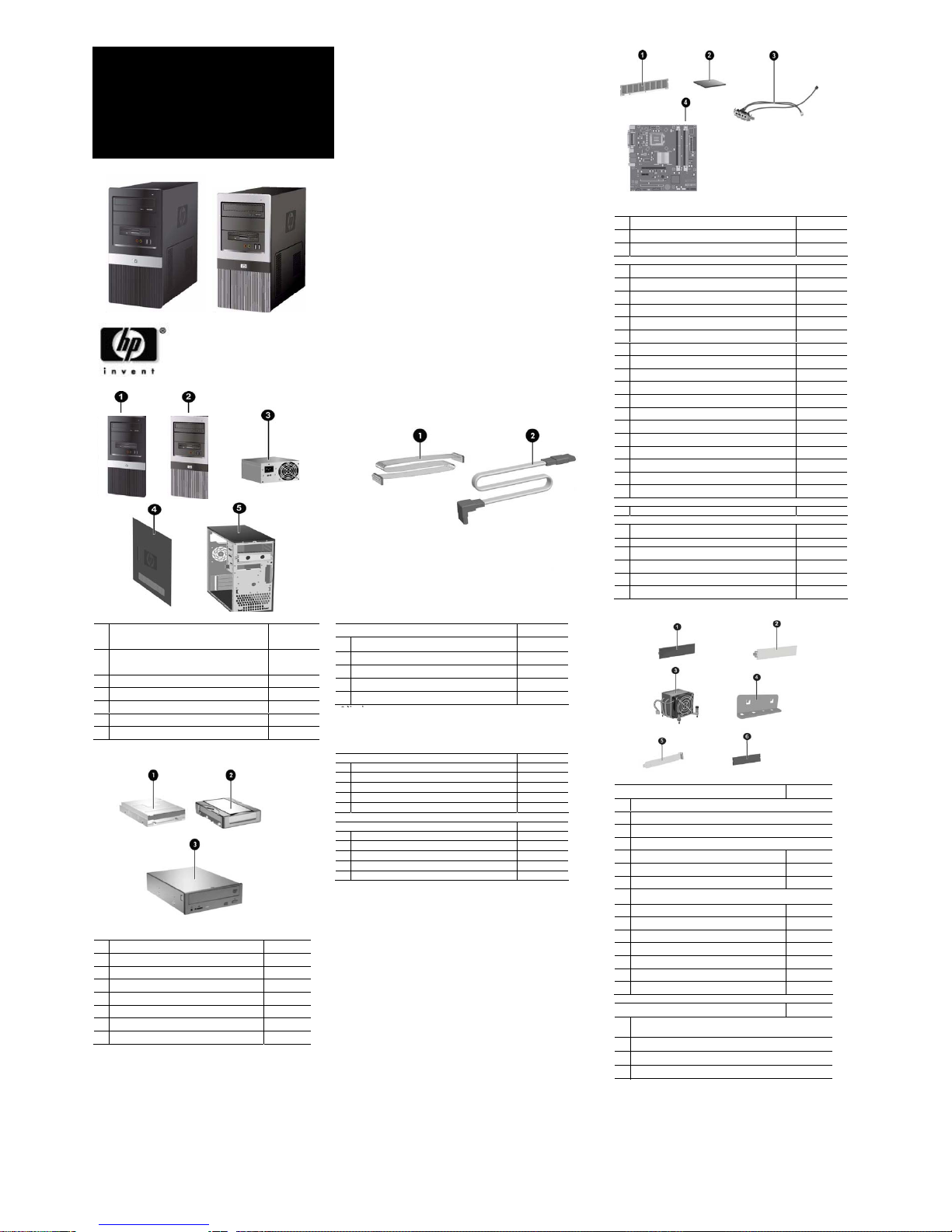
Standard and Optional Boards
Memory modules
1 MEM DIMM 1GB PC2-6400,CL6 418951-001
* MEM DIMM 512MB PC2-6400 CL6 418952-001
* DIMM, MEMORY, 2GB, PC2-6400, CL6 457624-001
Intel Processors with alchohol pad and thermal grease
* SPS-PROC,CEL-L 420, 1.6GHZ, 512K, A-1 449164-001
* SPS-PROC,CEL-L 430, 1.8GHZ, 512K, A-1 449165-001
2 SPS-PROC,CEL-L 440, 2.0GHZ, 512K, A-1 449166-001
* SPS-PROC IC, Conroe-E4500,2.2GHz,2M,M-0 449452-001
* SPS-PROC,IC,uP,Conroe-E4600,2.4GHz2M,M-0 462569-001
SPS-PROC,ICuP,WolfDale-E8400,3.0GHz6M,C0 466169-001
SPS-PROC,ICuP,WolfDaleE8500,3.16GHz6M,C0 466170-001
SPS-PROC,ICuP,WolfDaleE8200,2.66GHz6M,C0 466171-001
SPS-PROC,ICuP,YorkfldQ9450,2.66GHz12M,C0 466173-001
SPS-PROC Yorkfld-Q9550,2.83GHz,12M,C-0 465758-001
* SPS-PROC,IC,uP,PentiumE2160,1.8GH,1M,M-0 457622-001
* SPS-PROC Pentium E2180,2.0GHz,1M,M-0 457656-001
* SPS-PROC,uP,Pentium E2200,2.2GHz,1M,M-0 465216-001
* SPS-PROC Celeron E1200,1.6GHz,512K,M-0 468589-001
* SPS-PROC Core2Duo-E4600 2.2G 800DC (C)77 466619-001
* SPS-PROC,ICuP,YorkfldQ9300,2.5GHz6M,C-0 466172-001
* SPS-PROC Pentium E2220,2.4GHz,1M,M-0 480714-001
3 CA,USB,W/PCB BD, MT 480728-001
System board with alcohol and thermal grease
4 BD, SYS dx271x 480734-001
Other boards
* Broadcom Gb NIC PCIe, FH 430654-001
* Intel Gb NIC PCIe, FH 398754-001
* MDM, PCI modem, V92, FH 398661-001
* BD,1394 3-PORT PCI CARD 441448-001
* PCA,GRAF,PCIx16,DMS59,256MB,ATIX2400 462477-001
* CARD,GRAFX,X16,DL-DVII/TV,256,G86 445743-001
* Not shown
# Spared with alcohol wipe and thermal grease
Miscellaneous Parts
Miscellaneous hardware kit. Includes: 480730-001
1 5.25” drive bezel blank without metal shield (1 ea)
2 Diskette drive bezel without metal shield, silver (1 ea)
* IO SHIELD ASSY, KUNLUNSHAN (1 ea)
* Rubber foot (2 ea)
3 Heatsink with alcohol pad and thermal grease 480732-001
4 Cover slot lock (1 ea)
5 Cover slot (2 ea)
6 3.5” diskette drive bezel without metal shield (carbonite) (1 ea)
* System Fan 440992-001
* Media Card Reader 407187-001
* USB optical mouse carbonite 390938-001
* PS/2 scroll mouse 390937-001
* PS/2 optical Mouse 417966-001
* Internal speaker 480733-001
* PWR-LED SWITCH, MT 481012-001
Miscellaneous screw kit, includes 480729-001
*
#6-32 x 0.25 lg pan head (10 ea, for power supply, cover slot lock
and motherboard.)
*
#6-32 x 0.187 lg hi top (6 ea)
*
SCR GG M3,TT,HI/TOP,S15IPX5MM SPARE,RoHS (4 ea)
* SCR_6-32_T15 Lock (1 EA)
dx2710/dx2718 © 2008 Hewlett-Packard Development
Company, L.P.
HP and the HP logo are trademarks of Hewlett-Packard
Development Company, L.P.
Intel and Celeron are US registered trademarks of Intel
Corporation. All other product names mentioned herein
may be trademarks of their respective companies.
HP
shall not be liable for technical or editorial errors or
omissions contained herein. The information in this
document is provided “as is” without warranty of any kind
and is subject to change without notice. The warranties for
HP products are set forth in the express limited warranty
statements accompanying such products. Nothing herein
should be construed as constituting an additional
warranty
February 2008
Document Part Number 483940-001
Blanks Cables
Cable kit
480731-001
1 Diskette drive cable
2 SATAII 3G, 180mm,RoHS ,ST-ST,black
* SATAII 3G, 180mm,RoHS ,ST-ST,blue
* RJ11 cable
198220-005
* PORT 2ND SERIAL
392414-001
Keyboards (not illustrated)
KYBD,PS/2, BASIC, VISTA 435302-xxx
* International -B31
* Peoples Republic of China -AA1
* Taiwanese -AB1
* Thai -281
* KOR -KD1
KYBD USB, Basic, Vista 435382-xxx
* International -B31
* Peoples Republic of China -AA1
* Taiwanese -AB1
* Thai -281
* KOR -KD1
* Not shown
Mass Storage Device
1 Diskette drive, 3.5-inch 435420-001
2 80GB, SATA 3.0Gb 449978-001
* 160GB, SATA 3G 449979-001
* 250GB, SATA 3G 449980-001
* 500GB, SATA 3G 457909-001
3 DRV,DVDROM,SATA,16X 419496-001
* DRV,COMBO,SATA, ODD,48/32 419497-001
* DRV, ODD,SATA,16X,LS,SM,DVD RW bPC 447310-001
* Not shown
System Unit
1
Front bezel (cardbonite) with diskette drive bezel
and 2 - 5.25" bezel. (See Miscellaneous parts for
kit contents) for dx2710 MT model
480726-001
2
Front bezel (carbonite and silver) with diskette
drive bezel and 2- 5.25” bezel blanks for dx2718
MT models
480727-001
3
Power supply, 250W PFC, MT 480723-001
*
Power supply, 300W PFC, MT 480724-001
4
Access panel used on Alamo, MT 480725-001
5
Chassis not spared
* Not shown
HP Compaq Business Desktop
dx2710/dx2718
Microtower Models
Illustrated Parts Map
Intel® Core™ 2 processors, Intel Pentium®
processors, or Intel Celeron® processors
Page 2
Deleting a Password
1. Turn on or restart the computer. If you are in Windows, click Start > Shut Down > Restart the Computer. To delete
the setup password, run Computer Setup (F10).
2. When the key icon appears, type your current password followed by a slash (/) or alternate delimiter character as
shown. Example: currentpassword/
3. Press the Enter key.
E17
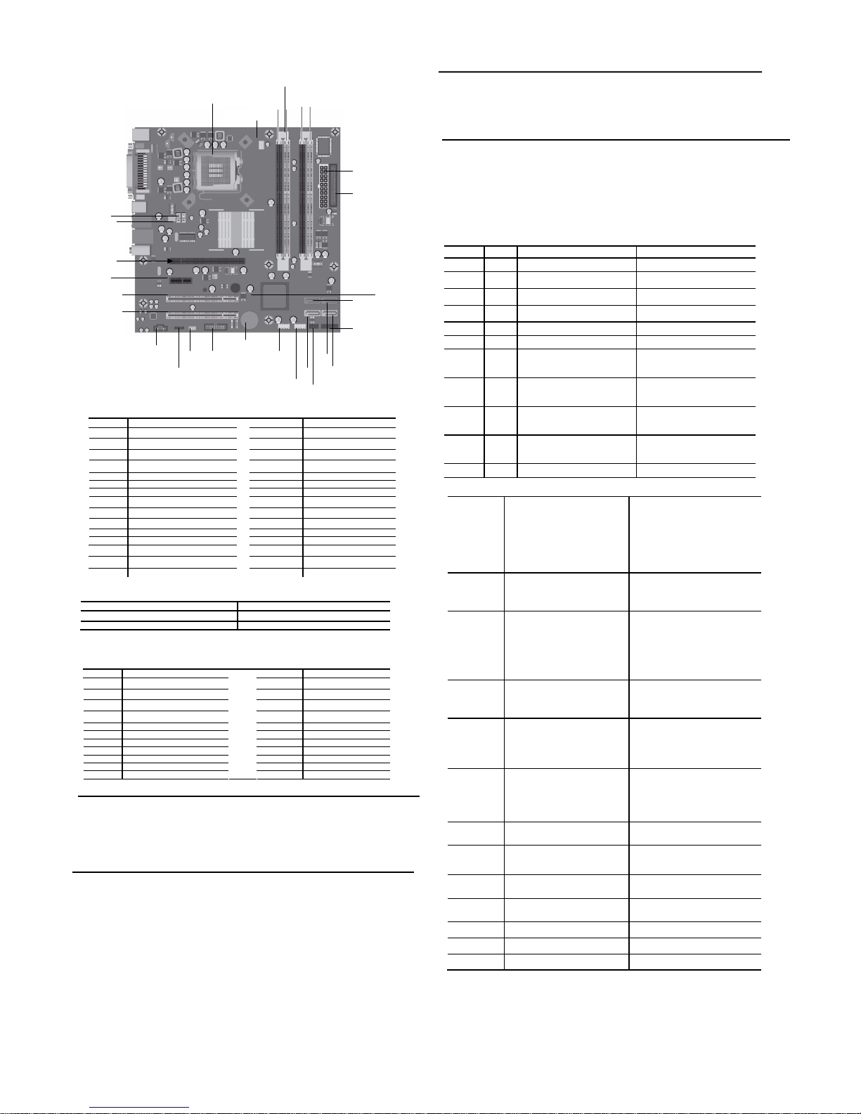
System Board Connectors and Jumpers (position of some untitled components may vary in location)
Label
Component Label Component
XU1 Processor socket E17 Clear CMOS jumper
CPU_FAN CPU fan J17 Front panel header
DIMM1 Memory socket 1 XBT1 Real-time-clock battery
DIMM2 Memory socket 2 P26 Front audio header
DIMM3 Memory socket 3 P4 CD in audio
DIMM4 Memory socket 4 PCI 1 PCI 1 connector
FLOPPY Diskette drive connector PCI 2 PCI 2 connector
PWR P1 ATX main power PCIE X 16 PCI-E X 16 connector
SATA0 SATA connector 0 PCIE X 1 PCI-E x1 connector
SATA1 SATA connector 1 SYS_FAN System fan
SATA2 SATA connector 2 P5 CPU 4 pin power connector
SATA3 SATA connector 3
J13 2ND SERIAL PORT HEADER
P24 FRONT USB 1
P7 Internal speaker header
P25 FRONT USB 2
E16 BOOT BLOCK HEADER
Clear_CMOS* CMOS
Clear CMOS 2-3
Normal (Default) 1-2
*: clear CMOS function only can be available when system is power off (power cord is disconnected)
System Hardware Interrupts
IRQ System Function IRQ System Function
0
Host controller
10
UHCI(D26:F2)
1 Keyboard 10 UHCI(D29:F2)
3 Serial port 1
10 Lan controller
4 Serial Port 2 11 UHCI(D29:F0)
5 VGA controller 11 UHCI(D29:F1)
5 UHCI(D26:F0) 11 EHCI(D29:F7)
5 UHCI(D26:F1) 11 EHCI(D26:F7)
6 FDC controller 11 SATA controller(D31:F5)
7 Parallel Port (LPT 1) 11 SATA controller(D31:F2)
9 HDA controll er 12 Mouse
10 LAN controller
Establishing a Password
1. Turn on or restart the computer. If you are in Windows, click Start > Shut Down >Restart the computer.
2. When the F10 Setup message appears in the lower-right corner of the screen, press the F10 key. Press Enter to by pass the tit le
screen, if necessary. If you do not press F10 whe n prompted, a restart will be necessary.
3. Select supervisor password and press enter key, and follow the instructions on the screen. You may also want to establish the
Password check at this time. This will allow you to specify when the password will be required.
4. Before exiting, click Save Settings and Exit.
Changing a Password
1. Turn on or restart the computer. If you are in Windows, click Start > Shut Down > Restart the Computer. To change the setup
password, run Computer Setup.
2. When the key icon appears, type your current password, a slash (/) or alternate de-limiter character, your new password, another
slash (/) or alternate delimiter character, and your new password again as shown:
current password/new password/new password.
NOTE: Type the new password carefully since the actual characters do not appear on the screen..
3. Press the enter key.
4. The new password will take effect the next time the computer is restarted.
Computer Setup (F10) Utility Features (not all features may be available)
System
Information
System S/N
Product Name
OwnerShip TAG
BIOS Version
BIOS Release Date
System Chipset Type
Processor Type
Processor Speed
CPU ID
Cache Size
Memory DIMM1
Memory DIMM2
Memory DIMM3
Memory DIMM4
DDR2 Memory Size
UUID
Chassis Serial Number
Asset TAG Number
Integrated MAC
Standard
CMOS
Features
System Date
System Time
Floppy Drive A
SATA Port 0
SATA Port 1
SATA Port 2
SATA Port 3
Legacy Mode Support
Halt On
Advanced
BIOS Features
F11 Prompt
Quick Power On Self Test
POST Delay Time (seconds)
Removable device Priority
Hard Disk Boot Priority
CD-ROOM Boot Priority
Network Boot Priority
First Boot Device
Second Boot Device
Third Boot Device
Fourth Boot Device
Boot Other Device
Load Boot Menu Selectable
APIC Mode
Hyper-Threading Technology
System Keyboard
Boot Up NumLock Status
Security Option
Advanced
Chipset
Features
On-Chip Frame Buffer Size
Disable MCHBAR MMIO
PEG/Onchip VGA control
DVMT Mode
DVMT/Fixed Memory Size
Init Display First
CPU Clock Ratio
Auto Detect PCI CLK
Spread Spectrum
Integrated
Peripherals
USB Controller
USB Legacy support
HD Audio
Onboard Lan Controller
Onboard Lan Boot ROM
Onboard FDC Controller
Serial Port 1
Serial Port 2
Parallel Port
Parallel Port Mode
ECP Mode Use DMA
Power
Management
Setup
PCI-E Wake on PME
ACPI Function
ACPI Suspend Type
Resume On PME
Resume On Ring
Resume by Alarm
Date(of Month) Alarm
Resume Time(hh:mm:ss) Alarm
HPET Support
HPET Mode
WDRT Support
WDRT Run/Stop
WDRT Count
Restore on AC/Power Loss
PnP/PCI
Configurations
Reset Configuration Data
Resources Controlled By
IRQ Resources
Hardware
Monitor Setup
FAN Controller
CPU Fan Speed
System Fan Speed
CPU Fan Fault Detect
SYS Fan Fault Detect
Load
Defaults
Setting
Set
Supervisor
Password
Set User
Password
Save Setting
and Exit
Exit Without
Saving
Note: See Computer Setup (F10) Utility Guide on the Library CD.
Diagnostic LEDs and Beeps
LED
Color LED/Beep Activity State/Message
Power Green On (S0) Computer on
Power Green 1 blink every 2 seconds (S1) Normal Suspend Mode
Power Green 1 blink every 2 seconds (S3) Suspend to RAM
Power Clear Off (S4) Suspend to Disk (if applicable)
Power Clear Off (S5) Computer off
Power Green Green when flashing ROM Boot block recovery w/Embedded Video
Power Red
CPU Fan weak (RPM < 1000) or not
turning, Display Warning message and
Long Beep for 5 sec and shut down.
CPU thermal shutdown
(Weak CPU fan speed or not running)
Power Red
Power LED flashes 5 seconds every 1
second, followed by 2 seconds pause,
and meanwhile, 5 beeps are heard
No memory installed / Pre-Video
memory error
Power Red
Power LED flashes 6 seconds every 1
second, followed by 2 seconds pause,
and meanwhile, 6 beeps are heard
Graphics card error (Pre-Video graphics
error)
Power Red
Power LED flashes 8 seconds every 1
second, followed by 2 seconds pause,
and meanwhile, 8 beeps are heard
System board failure or invalid ROM
basing on checksum.
Hard Drive Green Blinking Hard drive activity
Clearing CMOS*
The computer's configuration (CMOS) may occasionally be corrupted. If it is, it is necessary to clear the C M OS
memory using by performing the following procedure::
CAUTION: The power cord must be disconnected from the power source before changing the jumper setting.
(NOTE: All LEDs on the board should be OFF). Fa ilure to do so may damage the system board
1. Turn off the computer and any external devices, then disconnect the power cord from the power outlet.
2. Remove the access panel.
3. Clear CMOS with header E17.
4. Replace the access panel.
5. Connect the power cord to the power outlet.
6. Turn on the computer, allow it to start.
NOTE: Clearing CMOS clears all passwords.
△
DIMM 2
CPU XU1 DIMM3 DIMM4
DIMM1
CPU
_
FAN
SYS_FAN
PCIE X 1
PCI 1
PCI 2
PCIE X 16
P5
FRONT PANEL
HEADER
FLOPPY
PWR P1
SATA0
P26
P4
XBT1
P24
P25
SATA3 SATA2
SATA1 P7
J13
E16
 Loading...