

Page 1
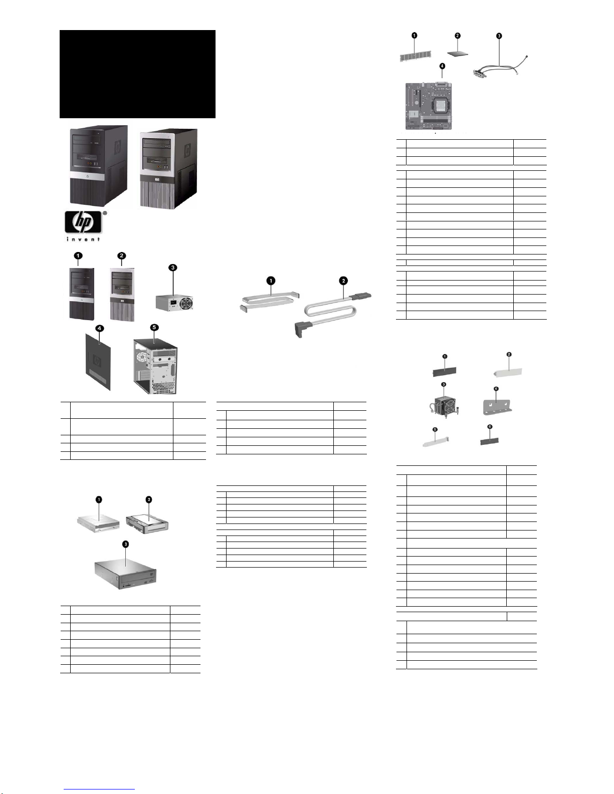
Standard and Optional Boards
Memory modules
1 MEM DIMM 1GB PC2-6400,CL6 418951-001
* MEM DIMM 512MB PC2-6400 CL6 418952-001
* DIMM, MEMORY, 2GB, PC2-6400, CL6 457624-001
AMD Processors with alchohol pad and thermal grease
* SPS-PROC Athlon-1C,1640B,2.7GHz,45W,G2 465304-001
* SPS-PROC Ath-64 X2,4450B,2.3GHz,1M,G2 465303-001
2 SPS-PROC Phenom-3C,8600S,2.3GHz,95W 466174-001
* SPS-PROC Phenom-3C,8700B,2.5GHz,95W 466175-001
* SPS-PROC Phenom-4C,9500S,2.2GHz,95W 465458-001
SPS-PROC Phenom-4C,9600B,2.3GHz,95W 465459-001
SPS-Semp-64,LE-1200,2.1GHz,512K,G1 460341-001
SPS-PROC Semp-64,LE-1250,2.2GHz,512K,G2 458068-001
SPS-PROC Semp-64,LE-1300,2.3GHz,512K,G2 458069-001
3 SPS-CA ASSY, FRONT USB+AUDIO 482955-001
System board with alcohol and thermal grease
4 SPS-BD SYSTEM MT dx235x 480030-001
Other boards
* Broadcom Gb NIC PCIe, FH 430654-001
* Intel Gb NIC PCIe, FH 398754-001
* MDM, PCI modem, V92, FH 398661-001
* BD,1394 3-PORT PCI CARD 441448-001
* PCA,GRAF,PCIx16,DMS59,256MB,ATIX2400 462477-001
* CARD,GRAFX,X16,DL-DVII/TV,256,G86 445743-001
* Not shown
# Spared with alcohol wipe and thermal grease
Miscellaneous Parts
Miscellaneous hardware kit. Includes: 483016-001
1
5.25” drive bezel blank without metal shield (1
ea)
2
SPS-BEZEL, 3.5" FDD BLANK, BTX, MT,
SFF
459913-001
* IO SHIELD ASSY, Krakatoa (1 ea)
* Rubber foot (2 ea) 370708-001
3 Heatsink with alcohol pad and thermal grease 482951-001
4 Cover slot lock (1 ea)
?
5 Cover slot (2 ea) ?
6 3.5” diskette drive bezel without metal shield (carbonite) (1 ea)
* System Fan 482954-001
* Media Card Reader 407187-001
* USB optical mouse carbonite 390938-001
* PS/2 scroll mouse 390937-001
* PS/2 optical Mouse 417966-001
* Internal speaker 482950-001
* SPS-CABLE, GEN, PWR SWT, LED 482953-001
Miscellaneous screw kit, includes 482956-001
*
#6-32 x 0.25 lg pan head (10 ea, for power supply, cover slot lock
and motherboard.)
*
#6-32 x 0.187 lg hi top (6 ea)
*
SCR GG M3,TT,HI/TOP,S15IPX5MM SPARE,RoHS (4 ea)
* SCR_6-32_T15 Lock (1 EA)
* SCRM4.8*12.19mmFlatHead,Philips,RoHS (4 ea)
* Not shown
dx2355/dx2358 © 2008 Hewlett-Packard Development
Company, L.P.
HP and the HP logo are trademarks of Hewlett-Packard
Development Company, L.P.
Phenom/Athlon/Sempron are US registered trademarks of Advanced
Micro Device (AMD) Corporation. All other product names
mentioned herein may be trademarks of their respective companies.
HP
shall not be liable for technical or editorial errors or
omissions contained herein. The information in this
document is provided “as is” without warranty of any kind
and is subject to change without notice. The warranties for
HP products are set forth in the express limited warranty
statements accompanying such products. Nothing herein
should be construed as constituting an additional
warranty
March 2008
Document Part Number: 489244-001
Blanks Cables
Cable kit
1 Diskette drive cable
2 SPS-CA,HD,SATA3G,10
392307-001
* SPS-CABLE, HDD, SATA 100mm
449283-001
* RJ11 cable
* PORT 2ND SERIAL
392414-001
* Not shown
Keyboards (not illustrated)
KYBD,PS/2, BASIC, VISTA 435302-xxx
* International -B31
* Peoples Republic of China -AA1
* Taiwanese -AB1
* Thai -281
* KOR -KD1
KYBD USB, Basic, Vista 435382-xxx
* International -B31
* Peoples Republic of China -AA1
* Taiwanese -AB1
* Thai -281
* KOR -KD1
* Not shown
Mass Storage Device
1 Diskette drive, 3.5-inch 431452-001
2 80GB, SATA 3.0Gb 449978-001
* 160GB, SATA 3G 449979-001
* 250GB, SATA 3G 449980-001
* 500GB, SATA 3G 457909-001
3 DRV,DVDROM,SATA,16X 419496-001
* DRV,COMBO,SATA, ODD,48/32 419497-001
* DRV, ODD,SATA,16X,LS,SM,DVD RW bPC 447310-001
* Not shown
System Unit
1
Front bezel (cardbonite) with diskette drive bezel
and 2 - 5.25" bezel. (See Miscellaneous parts for
kit contents) for dx2355 MT model
482948-001
2
Front bezel (carbonite and silver) with diskette
drive bezel and 2- 5.25” bezel blanks for dx2358
MT models
481016-001
3
Power supply, 300W PFC, MT 482949-001
4
Access panel used on Alamo, MT 482952-001
5
Chassis not spared
* Not shown
HP Compaq Business Desktop
dx2355/dx2358
Microtower Models
Illustrated Parts Map
AMD Phenom™ Quad and Triple Core processors,
AMD Athlon™ 64 X2 Dual Core processors, AMD
Athlon 64 processors, and AMD Sempron™
processors
Page 2
Deleting a Password
1. Turn on or restart the computer. If you are in Windows, click Start > Shut Down > Restart the Computer. To delete
the setup password, run Computer Setup (F10).
2. When the key icon appears, type your current password followed by a slash (/) or alternate delimiter character as
shown. Example: currentpassword/
3. Press the Enter key.
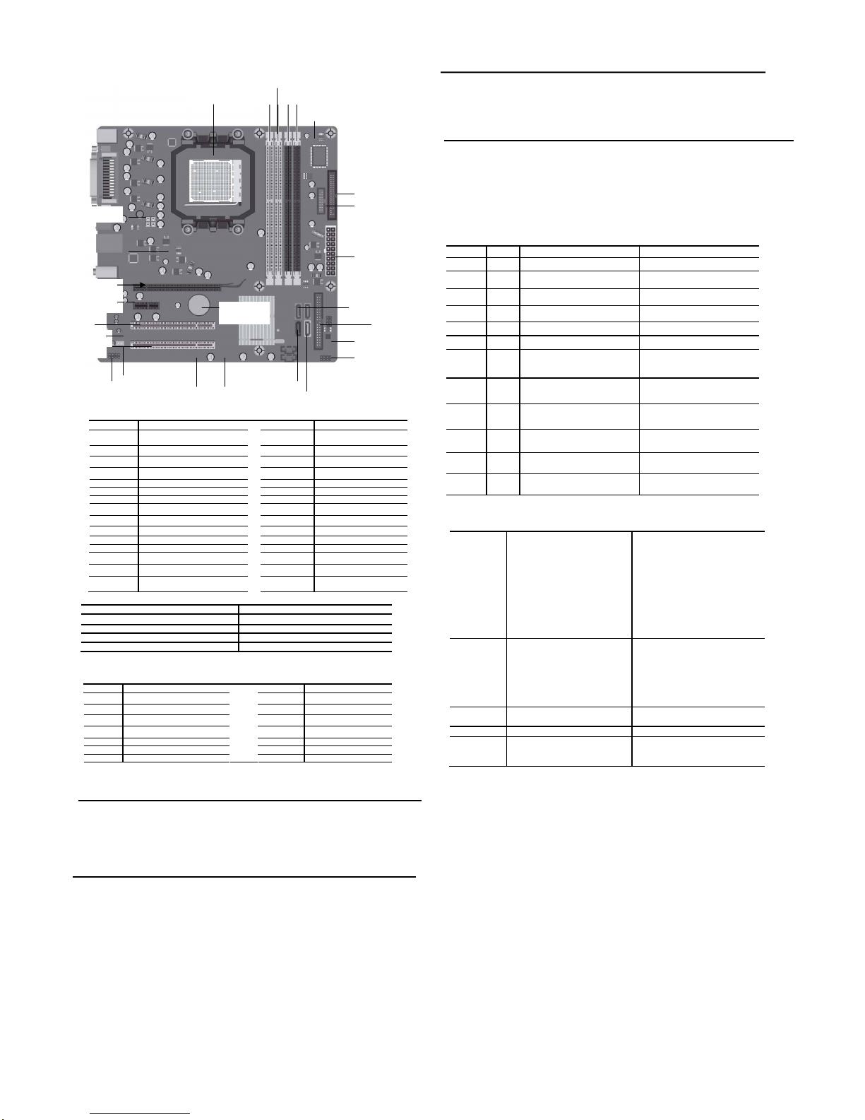
System Board Connectors and Jumpers (position of some untitled components may vary in location)
Label
Component Label Component
XU1 Processor socket E69 Clear CMOS/Clear Password
jumper
CPU_FAN CPU fan F_PANEL Front panel header
DIMM1 Memory socket 1 Primary_IDE Primary IDE connector
DIMM2 Memory socket 2 F_AUDIO Front audio header
DIMM3 Memory socket 3 F_LINE_IN F_LINE_IN audio
DIMM4 Memory socket 4 PCI 1 PCI 1 connector
FLOPPY Diskette drive connector PCI 2 PCI 2 connector
ATX_POWER ATX main power PCIE X 16 PCI-E X 16 connector
SATA0 SATA connector 0 PCIE X 1 PCI-E x1 connector
SATA1 SATA connector 1 Chassis_FAN System fan
SATA2 SATA connector 2 ATX_ CP U CPU 4 pin power connector
SATA3 SATA connector 3
SERIAL_B 2ND SERIAL PORT HEADER
F_USB1 FRONT USB 1
Speaker Internal speaker header
F_USB2 FRONT USB 2
E16 BOOT BLOCK HEADER
BATTERY Real-time-clock battery
Clear_CMOS/Password* CMOS/Password
Clear CMOS 1-2
Normal (Default) 2-3
Clear password 1-2
Normal (Default) 2-3
*: clear CMOS function only can be available when system is power off
(
p
ower cord is disconnected
)
System Hardware Interrupts
IRQ System Function IRQ System Function
0
Host controller
10 USB EHCI(DID:03F2)
1 Keyboard 10 SATA controller(DID:03F6)
3 Serial port 2 11 VGA controller
4 Serial Port 1
11 USB OHCI(DID:03F1)
5 LAN controller 11 SATA controller(DID:03F6)
6 FDC controller 12 Mouse
7 Parallel Port (LPT 1)
Establishing a Password
1. Turn on or restart the computer. If you are in Windows, click Start > Shut Down >Restart the computer.
2. When the F10 Setup message appears in the lower-ri ght corner of the screen, press the F10 key. Press Enter to bypass the title
screen, if necessary. If you do not press F10 whe n prompted, a restart will be necessary.
3. Select advanced/supervisor password/Enab le and follow the instructions on the screen. You may also want to establish the Password
check at this time. This will allow you to specify when the password will be required.
4. Before exiting, click Save Settings and Exit.
Changing a Password
1. Turn on or restart the computer. If you are in Windows, click Start > Shut Down > Restart the Computer. To change the setup
password, run Computer Setup.
2. When the key icon appears, type your current password, a slash (/) or alternate de-limiter character, your new password, another
slash (/) or alternate delimiter character, and your new password again as shown:
current password/new password/new password.
NOTE: Type the new password carefully since the actual characters do not appear on the screen..
3. Press the enter key.
4. The new password will take effect the next time the computer is restarted.
Computer Setup (F10) Utility Features (not all features may be available)
Main
System Date
System Time
Floppy Drive A
1
st
Drive
2nd Drive
3
rd
Drive
4
th
Drive
5
th
Drive
6
th
Drive
CPU TYPE
CPU Speed
CPU ID
Cache RAM(L2)
Cache RAM(L3)
Installed Memory
Memory Bank 1
Memory Bank 2
Memory Bank 3
Memory Bank 4
BIOS Version
Core Version
System S/N
Product Name
UUID
Asset Tag
Enter Asset Tag
Advanced
Primary Video Adaptor
Onboard Video Memory Size
PS/2 Mouse
Onboard LAN
Onboard LAN Boot ROM
PATA Controller
SATA Controller
SATA1 Controller Mode
SATA2 Controller Mode
Onboard Audio
Internal Speaker
SubSYS ID
Supervisor Password
User Password
USB Configuration
I/O Device Configuration
Hardware Monitor
Power
After AC Power Failure
S3
Virtualization T e chn ology
NX(No eXecute)
Boot
Boot-time Diagnostics Scrren Boot Device Priority
Exit
Note: See Computer Setup (F10) Utility Guide on the Library CD.
Diagnostic LEDs and Beeps
LED
Color LED/Beep Activity State/Message
Power Green On (S0) Computer on
Power Green 1 blink every 2 seconds (S1) Normal Suspend Mode
Power Green 1 blink every 2 seconds (S3) Suspend to RAM
Power Clear Off (S4) Suspend to Disk (if applicable)
Power Clear Off (S5) Computer off
Power Green Green when flashing ROM Boot block recovery w/Embedded Video
Power Red
CPU Fan weak (RPM < 1000) or not
turning, Display Warning message and
Long Beep for 5 sec and shut down.
CPU thermal shutdown
(Weak CPU fan speed or not running)
Power Red
1 short beep and 1 long beep followed by
a three second pause.
No memory installed / Pre-Video
memory error
Power Red
2 short beeps and 1 long beep followed
by a three second pause.
Graphics card error (Pre-Video graphics
error)
Power Red
3 short beeps and 1 long beep followed
by a three second pause.
CPU configuration error or invalid CPU
detected before graphics card initialized.
Power Red
2 short beeps followed by a three second
pause.
No floppy diskette or CD found.
Power Red
3 short beeps followed by three seconds
pause.
Upgrade the BIOS to proper version.
Clearing CMOS*
The computer's configuration (CMOS) may occasionally be corrupted. If it is, it is necessary to clear the C M OS
memory using by performing the following procedure::
CAUTION: The power cord must be disconnected from the power source before changing the jumper setting.
(NOTE: All LEDs on the board should be OFF). Fa ilure to do so may damage the system board
1. Turn off the computer and any external devices, then disconnect the power cord from the power outlet.
2. Remove the access panel.
3. Clear CMOS with header E69.
4. Replace the access panel.
5. Connect the power cord to the power outlet.
6. Turn on the computer, allow it to start.
NOTE: Clearing CMOS clears all passwords.
△
DIMM 2
CPU XU1 DIMM3 DIMM4DIMM1
CPU_FAN
Chassis
_
FAN
ATX_
CPU
PCIE X 1
PCI 1
PCI 2
PCIE X 16
F_AUDIO
F_LINE_IN
F
_
USB1
SATA0
F
_
USB2
spea
BATTERY
SATA1
Primary_IDE
F_PANEL
FLOPPY
SERIAL_B
SATA3 SATA2
E69
A
TX Powe
r
 Loading...