

Page 1

Page 2

Page 3

Table of contents
CRU Dataport DX115 kit installation ..................................................................................... 1
Introduction ............................................................................................................................. 1
Kit contents .............................................................................................................................. 1
Before you begin ..................................................................................................................... 1
Warnings and cautions ............................................................................................................. 2
Step 1—Preparing for component installation .............................................................................. 3
Accessing the internal components of the computer ....................................................... 3
Step 2—Installing the DX115 case into the optical drive bay ......................................................... 3
HP Z200 SFF and HP Z210 SFF computers .................................................................. 4
HP Z200, HP Z210 CMT, HP Z400, and HP xw4000 computers ................................... 9
HP xw6200, HP xw6400, and HP xw6600 computers ................................................ 11
HP Z600 and HP Z800 computers ............................................................................ 12
HP xw8000 and HP xw9000 computers .................................................................... 14
Step 3—Installing a hard disk in the DX115 carrier .................................................................... 14
Step 4—Completing the computer assembly .............................................................................. 17
Japanese 日本語 .................................................................................................................... 18
ENWW iii
Page 4

iv ENWW
Page 5

CRU Dataport DX115 kit installation
Introduction
This document describes how to install the CRU Dataport DX115® removable media kit in an HP
computer. The DX115 kit lets you install removable media in your computer.
Kit contents
●
Warranty information
●
DX115 unit (case, drive carrier, SATA power extension cable, screws, and lock key)
●
Installation document
●
Two SATA cables
●
Five M3 screws
●
One 6-32 screw
Before you begin
To view QuickSpecs and determine the compatibility of this product with your HP computer, see
http://www.hp.com/go/productbulletin.
© 2006–2011 Hewlett-Packard Development Company, L.P. Microsoft, Windows,
and Windows Vista are U.S. registered trademarks of Microsoft Corporation. Printed
in the U.S.
ENWW
Introduction
1
Page 6

Warnings and cautions
WARNING! Any surface or area of the equipment marked with this symbol indicates the
presence of a hot surface or hot component. If this surface is contacted, the potential for injury exists.
To reduce the risk of injury from a hot component, enable the surface to cool before touching.
WARNING! Any surface or area of the equipment marked with this symbol indicates the
presence of an electrical shock hazard. To reduce the risk of injury from electrical shock, do not open
any enclosed area marked with this symbol.
WARNING! To reduce the risk of electric shock or damage to your equipment:
— Do not disable the power cord grounding plug. The grounding plug is an important safety feature.
— Plug the power cord in a grounded (earthed) outlet that is easily accessible at all times.
— Disconnect power from the equipment by unplugging the power cord from the electrical outlet.
WARNING! To reduce the risk of serious injury, read the Safety & Comfort Guide. It describes
proper computer setup, posture, health, and work habits for computer users, and provides important
electrical and mechanical safety information. This guide is located at
http://www.hp.com/ergo and on
the documentation CD (if one is included with the product).
WARNING! If a product is shipped in packaging marked with this symbol, , the product must
always be lifted by two persons to avoid personal injury due to product weight.
CAUTION: Static electricity can damage the electronic components of the computer. Before
beginning these procedures, be sure you discharge static electricity by briefly touching a grounded
metal object.
CAUTION: To prevent damage to the computer, observe the following Electrostatic Discharge (ESD)
precautions while performing the system parts removal and replacement procedures:
— Work on a static-free mat.
— Wear a static strap to ensure that any accumulated electrostatic charge is discharged from your
body to the ground.
— Create a common ground for the equipment you are working on by connecting the static-free mat,
static strap, and peripheral units to that piece of equipment.
NOTE: HP accessories are for use in HP computer products. They have been extensively tested for
reliability and are manufactured to high quality standards.
2 CRU Dataport DX115 kit installation ENWW
Page 7

Step 1—Preparing for component installation
NOTE: Computer models vary. All illustrations are examples only.
Accessing the internal components of the computer
1. If you need help preparing the computer for this installation, consult the removal and replacement
procedures in the service guide for your computer at
http://www.hp.com/support/manuals.
2. Power down the computer, and then disconnect the power cord.
3. Power down all external devices, and then disconnect them from the computer.
4. Remove the side access panel.
Step 2—Installing the DX115 case into the optical
drive bay
See the steps for the applicable computer model in the following sections.
CAUTION: Insert or remove the carrier (with a disk drive) only when the workstation is shut down.
Other procedures may result in system hangs, data loss, or even drive damage. The component
supplier’s user guide describes a procedure for inserting or removing the carrier (with drive) while the
workstation is booted and then powering the drive via the power switch on the enclosure. Microsoft
Windows XP and Windows Vista do not support this action.
NOTE: The CRU Dataport DX115 does not fit in all optical drive bays. It is longer than most optical
drives. Install the CRU Dataport DX115 in the optical bay which best fits your computer configuration.
CAUTION: HP computer SAS disk drives are configured with a SAS-to-SATA adapter or cable. To
ensure proper connection, remove the adapter or cable before continuing with installation, as shown in
the following figure.
Figure 1 Removing the SAS to SATA adapter or cable
ENWW
Step 1—Preparing for component installation
3
Page 8
HP Z200 SFF and HP Z210 SFF computers
To install a DX115 case in an HP Z200 SFF or HP Z210 SFF computer:
1. Remove the front bezel:
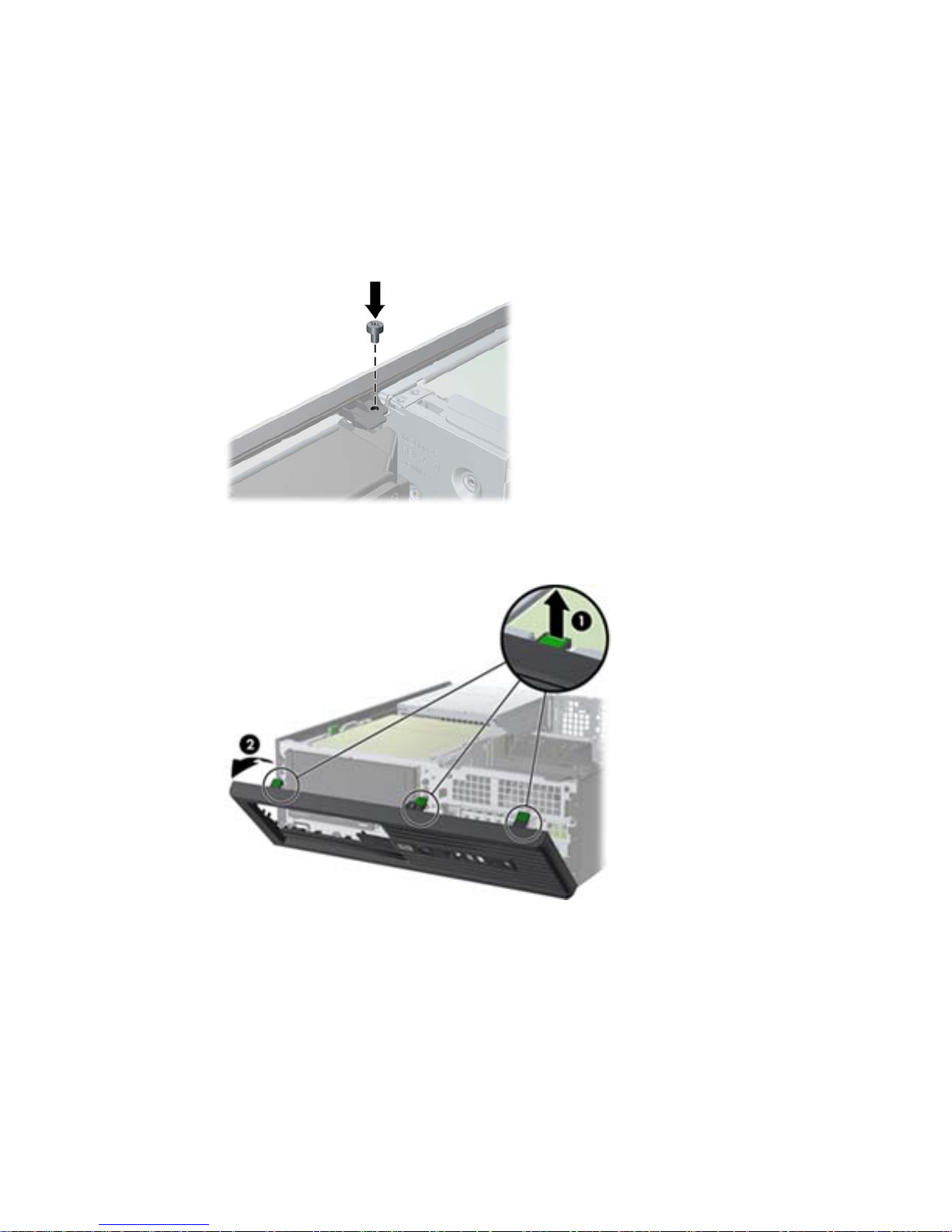
a. If necessary, remove the bezel security screw, located beside the middle bezel release tab.
Figure 2 Removing the bezel security screw
b. Lift the release tabs (1), and then rotate the front bezel off the chassis (2).
Figure 3 Removing the front bezel
4 CRU Dataport DX115 kit installation ENWW
Page 9

2. If necessary, remove the optical disk drive blank from the bezel:
a. On the inside of the bezel, push the two retaining tabs toward the outer edge of the bezel (1)
b. Slide the bezel blank back away from the bezel and to the left to remove it (2).
Figure 4 Removing the bezel blank
3. If an existing optical disk drive is present, remove it:
a. Rotate the drive cage to its upright position.
Figure 5 Rotating the drive cage up
ENWW
Step 2—Installing the DX115 case into the optical drive bay
5
Page 10

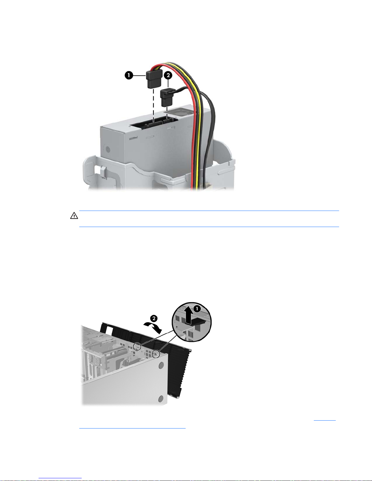
b. Disconnect the power cable (1) and data cable (2) from the rear of the optical drive.
Figure 6 Removing the cables
c. Rotate the drive cage back down to its normal position.
CAUTION: Check clearances on the cables when you rotate the drive cage. The cage may
pinch the cables and damage them if they are not routed correctly.
d. Press down on the green drive retainer button located on the left side of the drive to
disengage the drive from the drive cage. While pressing the drive retainer button, slide the
drive back until it stops, then lift it up and out of the drive cage.
Figure 7 Removing the optical drive
6 CRU Dataport DX115 kit installation ENWW
Page 11

4. Remove and discard the counter-sunk shipping screw at the side of the DX115 case.
Figure 8 Removing the shipping screw
5. Install four (black) M3 x 5mm screws (supplied in the kit) in the lower four mounting holes of the
DX115 case. Spare M3 screws supplied with your workstation are mounted on its chassis near the
optical bay.
Figure 9 Installing the guide screws
6. Position the guide screws on the drive into the J-slots in the drive bay. Then slide the drive toward
the front of the computer until it locks into place.
Figure 10 Installing the DX115 unit
ENWW
Step 2—Installing the DX115 case into the optical drive bay
7
Page 12

7. Rotate the drive cage to its upright position.
Figure 11 Rotating the drive cage up
8. If the cables are not already routed and attached to the system board:
a. Connect the SATA data cable to the system board connector labeled SATA1.
b. Route the data cable through the cable guides to keep the data cable from being pinched by
the drive cage when raising or lowering it. One guide is located on the bottom side of the
drive cage. The other is part of the chassis frame under the drive cage. Route the data cable
through these guides before connecting it to the optical drive.
Figure 12 Routing the drive cable
8 CRU Dataport DX115 kit installation ENWW
Page 13
9. Connect the power cable (1) and data cable (2) to the rear of the DX115 case.
Figure 13 Connecting the power and data cables
10. Carefully rotate the drive cage back down to its normal position.
CAUTION: Check clearances on the cables when you rotate the drive cage. The cage may
pinch the cables and damage them if they are not routed correctly.
HP Z200, HP Z210 CMT, HP Z400, and HP xw4000 computers
1. Remove the front bezel from the computer to access the optical bays.
a. Lift the tab (1).
b. Pivot the bezel to disengage the lower edge (2).
Figure 14 Removing the front bezel
2. Remove and discard the counter-sunk shipping screw at the side of the DX115 case. See Figure 8
Removing the shipping screw on page 7.
ENWW
Step 2—Installing the DX115 case into the optical drive bay
9
Page 14

3. Install four M3 x 5mm screws (black) in the lower four mounting holes. See Figure 9 Installing the
guide screws on page 7. Spare M3 screws are supplied with your workstation and mounted on its
chassis near the optical bay.
4. Lift the green release lever for the optical bay and slide the DX115 unit into the bay until it is
stopped by the release latch. The following figures show examples of release levers and their
locations.
Figure 15 Installing the DX115 case in an HP Z210 CMT and HP Z400 workstation mini-tower
configuration
Figure 16 Installing the DX115 case in an HP Z210 CMT desktop configuration
10 CRU Dataport DX115 kit installation ENWW
Page 15
5. Install one (supplied) M3 x 5mm screw (black) for each DX115 unit for shipping support as
shown. Additional M3 x 5mm screws are located on the chassis front side under the bezel.
CAUTION: Failure to install the shipping screw might result in damage to the removable hard
drive system.
Figure 17 Installing the shipping support screw
HP xw6200, HP xw6400, and HP xw6600 computers
1. Remove the front bezel from the computer. See Figure 14 Removing the front bezel on page 9.
2. Remove and discard the counter-sunk shipping screw at the side of the DX115 case. See
Figure 8
Removing the shipping screw on page 7.
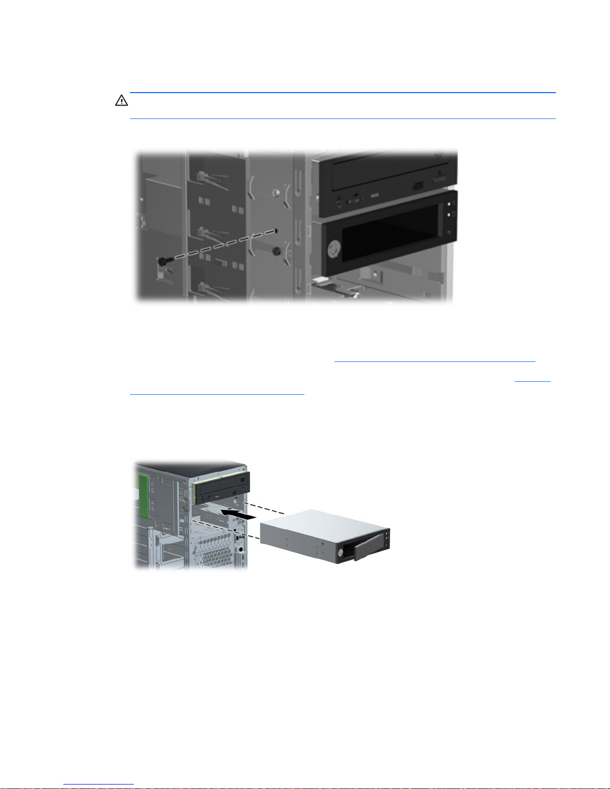
3. Gently slide the DX115 unit into the chassis until it locks into place, as shown in the following
figure.
Figure 18 Installing the DX115 case
ENWW
Step 2—Installing the DX115 case into the optical drive bay
11
Page 16

4. Install one (supplied) 6-32 x 1/4 in. screw (silver) for each DX115 unit for shipping support.
CAUTION: Failure to install the shipping screw might result in damage to the removable hard
drive system.
Figure 19 Installing the shipping support screw
HP Z600 and HP Z800 computers
1. For HP Z800 computers:
●
Remove the airflow guide to enable access to the optical bays.
●
Remove the card support to enable access to the system board connectors.
2. Remove and discard the counter-sunk shipping screw at the side of the DX115 case. See
Figure 8
Removing the shipping screw on page 7.
3. Lift and hold the drive release latch at the green touch point (1) while sliding the DX115 case into
the bay (2). When the front of the drive is near its final position, release the latch, but continue to
slide the drive inward until the latch closes and engages the drive.
Figure 20 Installing the DX115 case
12 CRU Dataport DX115 kit installation ENWW
Page 17

4. Install one (supplied) M3 x 5mm screw (black) for each DX115 unit for shipping support.
CAUTION: Failure to install the shipping screw might result in damage to the removable hard
drive system.
Figure 21 Installing the shipping support screw
ENWW
Step 2—Installing the DX115 case into the optical drive bay
13
Page 18

HP xw8000 and HP xw9000 computers
1. Remove the front bezel from the computer. See Figure 14 Removing the front bezel on page 9.
2. Remove and discard the counter-sunk shipping screw at the side of the DX115 case. See
Figure 8
Removing the shipping screw on page 7.
3. Lift and hold the drive release latch at the touch point (1) while sliding the DX115 case into the
bay (2). When the front of the drive is near its final position, release the latch, but continue to slide
the drive inward until the latch closes and engages the drive.
Figure 22 Installing the DX115 case
4. Install the M3 x 5mm screw (black) for each DX115 unit for shipping support. Spare M3 screws
supplied with your workstation are mounted on its chassis.
CAUTION: Failure to install the shipping screw might result in damage to the removable hard
drive system.
Figure 23 Installing the shipping support screw
Step 3—Installing a hard disk in the DX115 carrier
Some product options may require you to install a hard drive in the DX115 carrier. For additional
information, see:
●
The CRU Dataport DX115 User’s Guide for SATA or SAS removable drive enclosures
●
The CRU Dataport website at
http://www.cru-dataport.com/htmldocs/products/dataexpress/
dx115.html
14 CRU Dataport DX115 kit installation ENWW
Page 19

CAUTION: Insert or remove the carrier (with a disk drive) only when the workstation is shut down.
Other procedures may result in system hangs, data loss, or even drive damage. The component
supplier’s user guide describes a procedure for inserting or removing the carrier (with drive) while the
workstation is booted and then powering the drive via the power switch on the enclosure. Microsoft
Windows XP and Windows Vista do not support this action.
NOTE: You do not have to remove the DX115 case from the computer for this step.
To install the hard drive:
1. Remove the locking screws from the sides of the carrier.
Figure 24 Removing the locking screws
2. Remove the carrier cover by raising the front end of the cover (1) and pulling it away from the slot
in the rear of the carrier (2).
Figure 25 Removing the carrier cover
3. Orient the drive so that the data and power connectors face the rear of the carrier.
4. Place the drive into the front end of the carrier.
ENWW
Step 3—Installing a hard disk in the DX115 carrier
15
Page 20

5. Slide the drive all the way to the rear end of the carrier so that the power and data connectors
mate with the carrier adapter.
Figure 26 Installing the drive
6. Replace the cover by aligning the tab on the rear of the cover with the slot on the rear of the
carrier (1) and then rotating the front of the cover onto the carrier (2).
Figure 27 Replacing the cover
16 CRU Dataport DX115 kit installation ENWW
Page 21

7. Replace the locking screws in the sides of the carrier.
Figure 28 Replacing the locking screws
Step 4—Completing the computer assembly
CAUTION: Insert or remove the carrier (with a disk drive) only when the workstation is shut down.
Other procedures may result in system hangs, data loss, or even drive damage. The component
supplier’s user guide describes a procedure for inserting or removing the carrier (with drive) while the
workstation is booted and then powering the drive via the power switch on the enclosure. Microsoft
Windows XP and Windows Vista do not support this action.
1. After the drive case is installed in the computer, insert the drive carrier into the case.
a. Press on the left side of the handle (1) to open the door.
b. Insert the drive carrier.
c. If shipping or moving the computer, lock the carrier by inserting the key (2) and turning it
counterclockwise (3).
CAUTION: Always lock the drive before shipping or moving the computer. Failure to do so
might result in damage to your removable hard drive system.
Figure 29 Locking the carrier
ENWW
Step 4—Completing the computer assembly
17
Page 22

2. Connect the power (1) and data (2) cables to the primary (upper) ports on the unit.
Figure 30 Power and data ports
3. Connect the opposite end of the data cable to the appropriate connector on the system board or
controller card.
●
Connect SATA drives to SATA ports, and SAS drives to SAS ports, starting with the lowestnumbered available port.
●
For HP Z400 and Z600 computers, the blind-mate cables for the internal hard drive bays
may require adjustment at the system board, based on the computer drive configuration.
Consult the User Guide or the Maintenance and Service Guide for your computer for
additional information.
4. To prepare your installed hard drive for operation, see the appropriate hard drive documentation.
5. Replace the computer bezel and bezel security screw, if applicable.
6. Reinstall the card support, if applicable.
7. Reinstall the airflow guide, if applicable.
8. Reinstall the side access panel.
9. Reconnect all external devices.
10. Restore power to the computer and all external devices.
Japanese 日本語
This document is available in Japanese. See http://www.hp.com/support/manuals, then select your
product and select Japanese from the drop down Manual Language menu.
このドキュメントは日本語版が用意されています。
http://www.hp.com/support/manuals にアクセ
スし、ご使用のワークステーション製品を選択し、Manual Language ドロップダウン メニューか
ら Japanese を選択してください。
18 CRU Dataport DX115 kit installation ENWW
 Loading...