

Page 1

December 17, 2009December 17, 2009
HP Pavilion dv4 Entertainment PC
Maintenance and Service Guide
Document Part Number: 598157-001
December 2009
This guide is a troubleshooting reference used for maintaining and servicing the computer. It provides
comprehensive information on identifying computer features, components, and spare parts; troubleshooting
computer problems; and performing computer disassembly procedures.
Page 2

© Copyright 2009 Hewlett-Packard Development Company, L.P.
ATI and ATI Mobility Radeon are trademarks of Advanced Micro Devices, Inc. Bluetooth is a trademark owned by its proprietor and
used by Hewlett-Packard Company under license. Intel, Arrandale, and Core are trademarks of Intel corporation in the U.S. and other
countries. Microsoft and Windows are U.S. registered trademarks of Microsoft Corporation. SD Logo is a trademark of its
The information contained herein is subject to change without notice. The only warranties for HP products and services are set forth in
the express warranty statements accompanying such products and services. Nothing herein should be construed as constituting an
additional warranty. HP shall not be liable for technical or editorial errors or omissions contained herein.
First Edition: December 2009
Document Part Number: 598157-001
proprietor.
Page 3

Safety warning notice
WARNING: To reduce the possibility of heat-related injuries or of overheating the computer, do not place the computer directly
Å
on your lap or obstruct the computer air vents. Use the computer only on a hard, flat surface. Do not allow another hard surface,
such as an adjoining optional printer, or a soft surface, such as pillows or rugs or clothing, to block airflow. Also, do not allow
the AC adapter to contact the skin or a soft surface, such as pillows or rugs or clothing, during operation. The computer and the
AC adapter comply with the user-accessible surface temperature limits defined by the International Standard for Safety of
Information Technology Equipment (IEC 60950).
Page 4

Contents
1 Product description
2 External component identification
Top components. . . . . . . . . . . . . . . . . . . . . . . . . . . . . . . . . . . . . . . . . . . . . . . . . . . . . . . . . . . . . . . . . . . . . . 2–1
TouchPad . . . . . . . . . . . . . . . . . . . . . . . . . . . . . . . . . . . . . . . . . . . . . . . . . . . . . . . . . . . . . . . . . . . . . . . 2–1
Lights . . . . . . . . . . . . . . . . . . . . . . . . . . . . . . . . . . . . . . . . . . . . . . . . . . . . . . . . . . . . . . . . . . . . . . . . . . 2–2
Buttons, speakers, and fingerprint reader . . . . . . . . . . . . . . . . . . . . . . . . . . . . . . . . . . . . . . . . . . . . . . . 2–3
Keys . . . . . . . . . . . . . . . . . . . . . . . . . . . . . . . . . . . . . . . . . . . . . . . . . . . . . . . . . . . . . . . . . . . . . . . . . . . 2–4
Display . . . . . . . . . . . . . . . . . . . . . . . . . . . . . . . . . . . . . . . . . . . . . . . . . . . . . . . . . . . . . . . . . . . . . . . . . 2–5
Front components. . . . . . . . . . . . . . . . . . . . . . . . . . . . . . . . . . . . . . . . . . . . . . . . . . . . . . . . . . . . . . . . . . . . . 2–6
Rear component . . . . . . . . . . . . . . . . . . . . . . . . . . . . . . . . . . . . . . . . . . . . . . . . . . . . . . . . . . . . . . . . . . . . . . 2–7
Right-side components. . . . . . . . . . . . . . . . . . . . . . . . . . . . . . . . . . . . . . . . . . . . . . . . . . . . . . . . . . . . . . . . . 2–8
Left-side components . . . . . . . . . . . . . . . . . . . . . . . . . . . . . . . . . . . . . . . . . . . . . . . . . . . . . . . . . . . . . . . . . . 2–9
Bottom components . . . . . . . . . . . . . . . . . . . . . . . . . . . . . . . . . . . . . . . . . . . . . . . . . . . . . . . . . . . . . . . . . . 2–10
Wireless antennas. . . . . . . . . . . . . . . . . . . . . . . . . . . . . . . . . . . . . . . . . . . . . . . . . . . . . . . . . . . . . . . . . . . . 2–11
Additional hardware components . . . . . . . . . . . . . . . . . . . . . . . . . . . . . . . . . . . . . . . . . . . . . . . . . . . . . . . 2–12
3 Illustrated parts catalog
Service tag . . . . . . . . . . . . . . . . . . . . . . . . . . . . . . . . . . . . . . . . . . . . . . . . . . . . . . . . . . . . . . . . . . . . . . . . . . 3–1
Computer major components . . . . . . . . . . . . . . . . . . . . . . . . . . . . . . . . . . . . . . . . . . . . . . . . . . . . . . . . . . . . 3–2
Display assembly subcomponents . . . . . . . . . . . . . . . . . . . . . . . . . . . . . . . . . . . . . . . . . . . . . . . . . . . . . . . . 3–9
Plastics Kit . . . . . . . . . . . . . . . . . . . . . . . . . . . . . . . . . . . . . . . . . . . . . . . . . . . . . . . . . . . . . . . . . . . . . . . . . 3–10
Mass storage devices . . . . . . . . . . . . . . . . . . . . . . . . . . . . . . . . . . . . . . . . . . . . . . . . . . . . . . . . . . . . . . . . . 3–11
Miscellaneous parts . . . . . . . . . . . . . . . . . . . . . . . . . . . . . . . . . . . . . . . . . . . . . . . . . . . . . . . . . . . . . . . . . . 3–12
Sequential part number listing . . . . . . . . . . . . . . . . . . . . . . . . . . . . . . . . . . . . . . . . . . . . . . . . . . . . . . . . . . 3–14
Maintenance and Service Guide iv
Page 5

Contents
4 Removal and replacement procedures
Preliminary replacement requirements . . . . . . . . . . . . . . . . . . . . . . . . . . . . . . . . . . . . . . . . . . . . . . . . . . . . 4–1
Tools required . . . . . . . . . . . . . . . . . . . . . . . . . . . . . . . . . . . . . . . . . . . . . . . . . . . . . . . . . . . . . . . . . . . . 4–1
Service considerations. . . . . . . . . . . . . . . . . . . . . . . . . . . . . . . . . . . . . . . . . . . . . . . . . . . . . . . . . . . . . . 4–1
Plastic parts . . . . . . . . . . . . . . . . . . . . . . . . . . . . . . . . . . . . . . . . . . . . . . . . . . . . . . . . . . . . . . . . . . . . . . 4–1
Grounding guidelines . . . . . . . . . . . . . . . . . . . . . . . . . . . . . . . . . . . . . . . . . . . . . . . . . . . . . . . . . . . . . . 4–2
Component replacement procedures . . . . . . . . . . . . . . . . . . . . . . . . . . . . . . . . . . . . . . . . . . . . . . . . . . . . . . 4–5
Service tag. . . . . . . . . . . . . . . . . . . . . . . . . . . . . . . . . . . . . . . . . . . . . . . . . . . . . . . . . . . . . . . . . . . . . . . 4–5
Computer feet . . . . . . . . . . . . . . . . . . . . . . . . . . . . . . . . . . . . . . . . . . . . . . . . . . . . . . . . . . . . . . . . . . . . 4–6
Battery. . . . . . . . . . . . . . . . . . . . . . . . . . . . . . . . . . . . . . . . . . . . . . . . . . . . . . . . . . . . . . . . . . . . . . . . . . 4–7
Hard drive . . . . . . . . . . . . . . . . . . . . . . . . . . . . . . . . . . . . . . . . . . . . . . . . . . . . . . . . . . . . . . . . . . . . . . . 4–8
Memory module . . . . . . . . . . . . . . . . . . . . . . . . . . . . . . . . . . . . . . . . . . . . . . . . . . . . . . . . . . . . . . . . . 4–10
RTC battery. . . . . . . . . . . . . . . . . . . . . . . . . . . . . . . . . . . . . . . . . . . . . . . . . . . . . . . . . . . . . . . . . . . . . 4–12
TV tuner . . . . . . . . . . . . . . . . . . . . . . . . . . . . . . . . . . . . . . . . . . . . . . . . . . . . . . . . . . . . . . . . . . . . . . . . 4–14
WLAN module . . . . . . . . . . . . . . . . . . . . . . . . . . . . . . . . . . . . . . . . . . . . . . . . . . . . . . . . . . . . . . . . . . 4–15
Optical drive . . . . . . . . . . . . . . . . . . . . . . . . . . . . . . . . . . . . . . . . . . . . . . . . . . . . . . . . . . . . . . . . . . . . 4–19
Keyboard. . . . . . . . . . . . . . . . . . . . . . . . . . . . . . . . . . . . . . . . . . . . . . . . . . . . . . . . . . . . . . . . . . . . . . . 4–20
Keyboard cover . . . . . . . . . . . . . . . . . . . . . . . . . . . . . . . . . . . . . . . . . . . . . . . . . . . . . . . . . . . . . . . . . . 4–23
Power button board . . . . . . . . . . . . . . . . . . . . . . . . . . . . . . . . . . . . . . . . . . . . . . . . . . . . . . . . . . . . . . . 4–25
Speaker assembly . . . . . . . . . . . . . . . . . . . . . . . . . . . . . . . . . . . . . . . . . . . . . . . . . . . . . . . . . . . . . . . . 4–26
Display assembly . . . . . . . . . . . . . . . . . . . . . . . . . . . . . . . . . . . . . . . . . . . . . . . . . . . . . . . . . . . . . . . . 4–27
Webcam/microphone module . . . . . . . . . . . . . . . . . . . . . . . . . . . . . . . . . . . . . . . . . . . . . . . . . . . . . . . 4–33
Top cover . . . . . . . . . . . . . . . . . . . . . . . . . . . . . . . . . . . . . . . . . . . . . . . . . . . . . . . . . . . . . . . . . . . . . . 4–34
Touchpad button board and bracket . . . . . . . . . . . . . . . . . . . . . . . . . . . . . . . . . . . . . . . . . . . . . . . . . . . 4–37
Fingerprint Reader board (select models only). . . . . . . . . . . . . . . . . . . . . . . . . . . . . . . . . . . . . . . . . . 4–39
Modem module (select models only) . . . . . . . . . . . . . . . . . . . . . . . . . . . . . . . . . . . . . . . . . . . . . . . . . 4–40
Bluetooth module (select models only) . . . . . . . . . . . . . . . . . . . . . . . . . . . . . . . . . . . . . . . . . . . . . . . 4–42
Audio board. . . . . . . . . . . . . . . . . . . . . . . . . . . . . . . . . . . . . . . . . . . . . . . . . . . . . . . . . . . . . . . . . . . . . 4–44
USB board. . . . . . . . . . . . . . . . . . . . . . . . . . . . . . . . . . . . . . . . . . . . . . . . . . . . . . . . . . . . . . . . . . . . . . 4–46
Power connector . . . . . . . . . . . . . . . . . . . . . . . . . . . . . . . . . . . . . . . . . . . . . . . . . . . . . . . . . . . . . . . . . 4–48
System board. . . . . . . . . . . . . . . . . . . . . . . . . . . . . . . . . . . . . . . . . . . . . . . . . . . . . . . . . . . . . . . . . . . . 4–50
RJ-11 connector (select models only). . . . . . . . . . . . . . . . . . . . . . . . . . . . . . . . . . . . . . . . . . . . . . . . . 4–53
Heat sink assembly . . . . . . . . . . . . . . . . . . . . . . . . . . . . . . . . . . . . . . . . . . . . . . . . . . . . . . . . . . . . . . . 4–55
Fan. . . . . . . . . . . . . . . . . . . . . . . . . . . . . . . . . . . . . . . . . . . . . . . . . . . . . . . . . . . . . . . . . . . . . . . . . . . . 4–57
Processor . . . . . . . . . . . . . . . . . . . . . . . . . . . . . . . . . . . . . . . . . . . . . . . . . . . . . . . . . . . . . . . . . . . . . . . 4–59
v Maintenance and Service Guide
Page 6

5 Setup Utility
Starting Setup Utility . . . . . . . . . . . . . . . . . . . . . . . . . . . . . . . . . . . . . . . . . . . . . . . . . . . . . . . . . . . . . . . . . . 5–1
Using Setup Utility. . . . . . . . . . . . . . . . . . . . . . . . . . . . . . . . . . . . . . . . . . . . . . . . . . . . . . . . . . . . . . . . . . . . 5–1
Changing the language of Setup Utility . . . . . . . . . . . . . . . . . . . . . . . . . . . . . . . . . . . . . . . . . . . . . . . . 5–1
Navigating and selecting in Setup Utility . . . . . . . . . . . . . . . . . . . . . . . . . . . . . . . . . . . . . . . . . . . . . . . 5–2
Displaying system information . . . . . . . . . . . . . . . . . . . . . . . . . . . . . . . . . . . . . . . . . . . . . . . . . . . . . . . 5–2
Restoring default settings in Setup Utility . . . . . . . . . . . . . . . . . . . . . . . . . . . . . . . . . . . . . . . . . . . . . . 5–2
Exiting Setup Utility . . . . . . . . . . . . . . . . . . . . . . . . . . . . . . . . . . . . . . . . . . . . . . . . . . . . . . . . . . . . . . . 5–3
Setup Utility menus . . . . . . . . . . . . . . . . . . . . . . . . . . . . . . . . . . . . . . . . . . . . . . . . . . . . . . . . . . . . . . . . . . . 5–3
Main menu . . . . . . . . . . . . . . . . . . . . . . . . . . . . . . . . . . . . . . . . . . . . . . . . . . . . . . . . . . . . . . . . . . . . . . 5–3
Security menu . . . . . . . . . . . . . . . . . . . . . . . . . . . . . . . . . . . . . . . . . . . . . . . . . . . . . . . . . . . . . . . . . . . . 5–3
System Configuration menu . . . . . . . . . . . . . . . . . . . . . . . . . . . . . . . . . . . . . . . . . . . . . . . . . . . . . . . . . 5–4
Diagnostics menu . . . . . . . . . . . . . . . . . . . . . . . . . . . . . . . . . . . . . . . . . . . . . . . . . . . . . . . . . . . . . . . . . 5–4
6 Specifications
Computer specifications. . . . . . . . . . . . . . . . . . . . . . . . . . . . . . . . . . . . . . . . . . . . . . . . . . . . . . . . . . . . . . . . 6–1
14.1-inch WXGA BrightView display specifications . . . . . . . . . . . . . . . . . . . . . . . . . . . . . . . . . . . . . . . . . 6–2
Hard drive specifications . . . . . . . . . . . . . . . . . . . . . . . . . . . . . . . . . . . . . . . . . . . . . . . . . . . . . . . . . . . . . . . 6–3
Blu-ray DVD±R/RW SuperMulti Double-Layer Drive with LightScribe specifications . . . . . . . . . . . . . . 6–4
DVD±RW SuperMulti Double-Layer Combo Drive with LightScribe specifications . . . . . . . . . . . . . . . . 6–5
System DMA specifications. . . . . . . . . . . . . . . . . . . . . . . . . . . . . . . . . . . . . . . . . . . . . . . . . . . . . . . . . . . . . 6–6
System interrupt specifications . . . . . . . . . . . . . . . . . . . . . . . . . . . . . . . . . . . . . . . . . . . . . . . . . . . . . . . . . . 6–7
System I/O address specification . . . . . . . . . . . . . . . . . . . . . . . . . . . . . . . . . . . . . . . . . . . . . . . . . . . . . . . . . 6–8
Contents
7 Backup and recovery
Overview . . . . . . . . . . . . . . . . . . . . . . . . . . . . . . . . . . . . . . . . . . . . . . . . . . . . . . . . . . . . . . . . . . . . . . . . . . . 7–1
Creating recovery discs . . . . . . . . . . . . . . . . . . . . . . . . . . . . . . . . . . . . . . . . . . . . . . . . . . . . . . . . . . . . . . . . 7–2
Backing up your information . . . . . . . . . . . . . . . . . . . . . . . . . . . . . . . . . . . . . . . . . . . . . . . . . . . . . . . . . . . . 7–3
Using Windows Backup and Restore . . . . . . . . . . . . . . . . . . . . . . . . . . . . . . . . . . . . . . . . . . . . . . . . . . 7–4
Using system restore points . . . . . . . . . . . . . . . . . . . . . . . . . . . . . . . . . . . . . . . . . . . . . . . . . . . . . . . . . 7–4
Performing a recovery . . . . . . . . . . . . . . . . . . . . . . . . . . . . . . . . . . . . . . . . . . . . . . . . . . . . . . . . . . . . . . . . . 7–5
Recovering from the recovery discs . . . . . . . . . . . . . . . . . . . . . . . . . . . . . . . . . . . . . . . . . . . . . . . . . . . 7–6
Recovering from the dedicated recovery partition (select models only) . . . . . . . . . . . . . . . . . . . . . . . 7–6
Maintenance and Service Guide vi
Page 7

Contents
8 Connector pin assignments
Audio-in (microphone). . . . . . . . . . . . . . . . . . . . . . . . . . . . . . . . . . . . . . . . . . . . . . . . . . . . . . . . . . . . . . . . . 8–1
External monitor. . . . . . . . . . . . . . . . . . . . . . . . . . . . . . . . . . . . . . . . . . . . . . . . . . . . . . . . . . . . . . . . . . . . . . 8–2
HDMI . . . . . . . . . . . . . . . . . . . . . . . . . . . . . . . . . . . . . . . . . . . . . . . . . . . . . . . . . . . . . . . . . . . . . . . . . . . . . . 8–3
RJ-11 (modem) (select models only) . . . . . . . . . . . . . . . . . . . . . . . . . . . . . . . . . . . . . . . . . . . . . . . . . . . . . . 8–4
RJ-45 (network) . . . . . . . . . . . . . . . . . . . . . . . . . . . . . . . . . . . . . . . . . . . . . . . . . . . . . . . . . . . . . . . . . . . . . . 8–5
Universal Serial Bus. . . . . . . . . . . . . . . . . . . . . . . . . . . . . . . . . . . . . . . . . . . . . . . . . . . . . . . . . . . . . . . . . . . 8–6
9 Power cord set requirements
Requirements for all countries and regions . . . . . . . . . . . . . . . . . . . . . . . . . . . . . . . . . . . . . . . . . . . . . . . . . 9–1
Requirements for specific countries and regions . . . . . . . . . . . . . . . . . . . . . . . . . . . . . . . . . . . . . . . . . . . . . 9–2
10Recycling
Battery . . . . . . . . . . . . . . . . . . . . . . . . . . . . . . . . . . . . . . . . . . . . . . . . . . . . . . . . . . . . . . . . . . . . . . . . . . . . 10–1
Display . . . . . . . . . . . . . . . . . . . . . . . . . . . . . . . . . . . . . . . . . . . . . . . . . . . . . . . . . . . . . . . . . . . . . . . . . . . . 10–1
Index
vii Maintenance and Service Guide
Page 8

Product description
Category Description
Product Name HP Pavilion dv4 Entertainment PC
Processors Intel Arrandale™ Single-Core i5-520M (2.4 GHz, 3 MB L3 cache, 1066 MHZ SC Turbo)
Intel Arrandale Single-Core i5-540M (2.53 GHz, 3 MB L3 cache, 1066 MHZ SC Turbo)
Chipset Intel™ HM55
Graphics Mobile Intel™ GMA Media Accelerator HD unified memory architecture (UMA, integrated) with
shared video memory:
■ Up to 268 MB of video memory on computer models equipped with 1 GB of main system
memory.
■ Up to 781 MB of video memory on computer models equipped with 2 GB of main system
memory.
■ Up to 1292 MB of video memory on computer models equipped with 3GB of main system
memory.
■ Up to 1293 MB of video memory on computer models equipped with 4GB of main system
memory (32-bit OS).
■ Up to 1759 MB of video memory on computer models equipped with 4GB of main system
memory (64-bit OS).
ATI Discrete Mobility Radeon™ HD4550 with 512 MB dedicated video memory
1
Panel 14.1-in WXGA BrightView (1280 × 800) display panel
16:10 wide aspect ratio
(Continued)
Maintenance and Service Guide 1–1
Page 9

Product description
Category Description
Memory 2 customer-accessible/upgradable memory module slots
Hard Drives Supports a 9.50-mm, 6.35-cm (2.50-in) hard drive
Optical drives 12.7-mm tray load
Audio High-definition audio
Supports dual-channel memory
Supports up to 8 GB of system RAM
1066-MHz, DDR3
Supports the following configurations:
8192 MB total system memory (4096 × 2, dual-channel)
6144 MB total system memory (4096 + 2048)
4096 MB total system memory (2048 × 2, dual-channel)
3072 MB total system memory (2048 + 1024)
2048 MB total system memory (1024 × 2, dual-channel)
2048 MB total system memory (2048 × 1)
1024 MB total system memory (1024 × 1)
Supports HP ProtectSmart Hard Drive Protection
Customer-accessible
Serial ATA
Supports the following hard drives:
500 GB, 7200-rpm
320 GB, 7200-rpm
250 GB, 7200-rpm
160 GB, 7200-rpm
Seria l ATA ( S ATA)
MultiBay weight saver
Customer-accessible
Supports the following drives:
Blu-ray ROM DVD±R/RW SuperMulti DL Drive with LightScribe
DVD±R/RW SuperMulti DL Drive with LightScribe
Meets SRS logo requirement
Supports Microsoft® premium requirements
Pavilion-branded Altec Lansing speakers
Modem 56K MDC V.92 data/fax modem (select models only)
(Continued)
1–2 Maintenance and Service Guide
Page 10

Category Description
Webcam/microphone VGA webcam
Fixed (no tilt)
Activity LED
640 × 480 by 24 frames per second
2 integrated omnidirectional digital microphones
Ethernet Integrated 10/100/1000 network interface card (NIC) for Discrete versions.
Integrated 10/100 network interface card (NIC) for UMA versions.
Wireless Integrated WLAN options by way of wireless module:
Intel WiFi Link 6200 802.11 a/b/g/n WLAN module
Intel WiFi Link 6200 802.11 a/b/g/n WLAN module + Bluetooth
IIntel WiFi Link 1000 802.11b/g/n WLAN module
Intel WiFi Link 1000 802.11 b/g/n WLAN module + Bluetooth
2 wireless antennas built into display assembly
Broadcom BCM2070 Bluetooth® 2.1 module (select models only)
External media cards One ExpressCard slot, supporting optional ExpressCard/54 cards
Digital Media Slot supporting Memory Stick (MS), Memory Stick Pro (MSP), MultiMediaCard
(MMC), Secure Digital (SD) Memory Card, and xD-Picture Card (XD).
Adapter (purchased separately) provides support for mini versions of SD, MMC, and MSP Duo
Product description
Ports Audio-in (stereo microphone)
Audio-out (stereo headphone)
RJ-11 modem (select models only)
HDMI v. 1.3b supporting 1080p with HDCP key
HP Smart Adapter power
Consumer infrared
eSATA (third USB port)
RJ-45 (Ethernet, includes link and activity lights)
USB 2.0
VGA (Dsub 15-pin) supports the following resolutions:
1920 × 1200 external resolution at 60 GHz (select models only)
1600 × 1200 external resolution at 75 GHz (select models only)
Hot plug/unplug with auto-detect
(Continued)
Maintenance and Service Guide 1–3
Page 11

Product description
Category Description
Docking Expansion port 3 supports HP xb Docking Station and HP Notebook QuickDock
Keyboard/pointing
devices
Power requirements 65-W and 90-W HP Smart Adapter with localized cable plug support (3-wire plug with ground
Security Kensington Security Lock
Operating system Preinstalled:
Serviceability End-user replaceable parts:
14.1-in keyboard
TouchPad with 2 buttons
Supports 2-way scroll
Taps enabled as default
pin, supports 3-pin DC connector)
Smart pin AC Adapter with localized cable plug support
Battery options:
3-cell, 4.40 Ah (47 Wh) Li-ion battery
6-cell, 2.20 Ah (47 Wh) Li-ion battery
6-cell, 2.20 Ah (55 Wh) Li-ion battery
6-cell, 2.55 Ah (55 Wh) Li-ion battery
12-cell, 2.20 Ah (95 Wh) Li-ion battery
Fingerprint Reader with Digital Persona Software Support (select models only)
Windows® 7 Professional (32 and 64-bit OS)
Windows 7 Premium (32 and 64-bit OS)
Windows 7 Basic (32-bit OS)
AC adapter
Battery (system)
Hard Drive
Memory modules
MiniCard components
RTC battery
Optical drive
1–4 Maintenance and Service Guide
Page 12
Top components
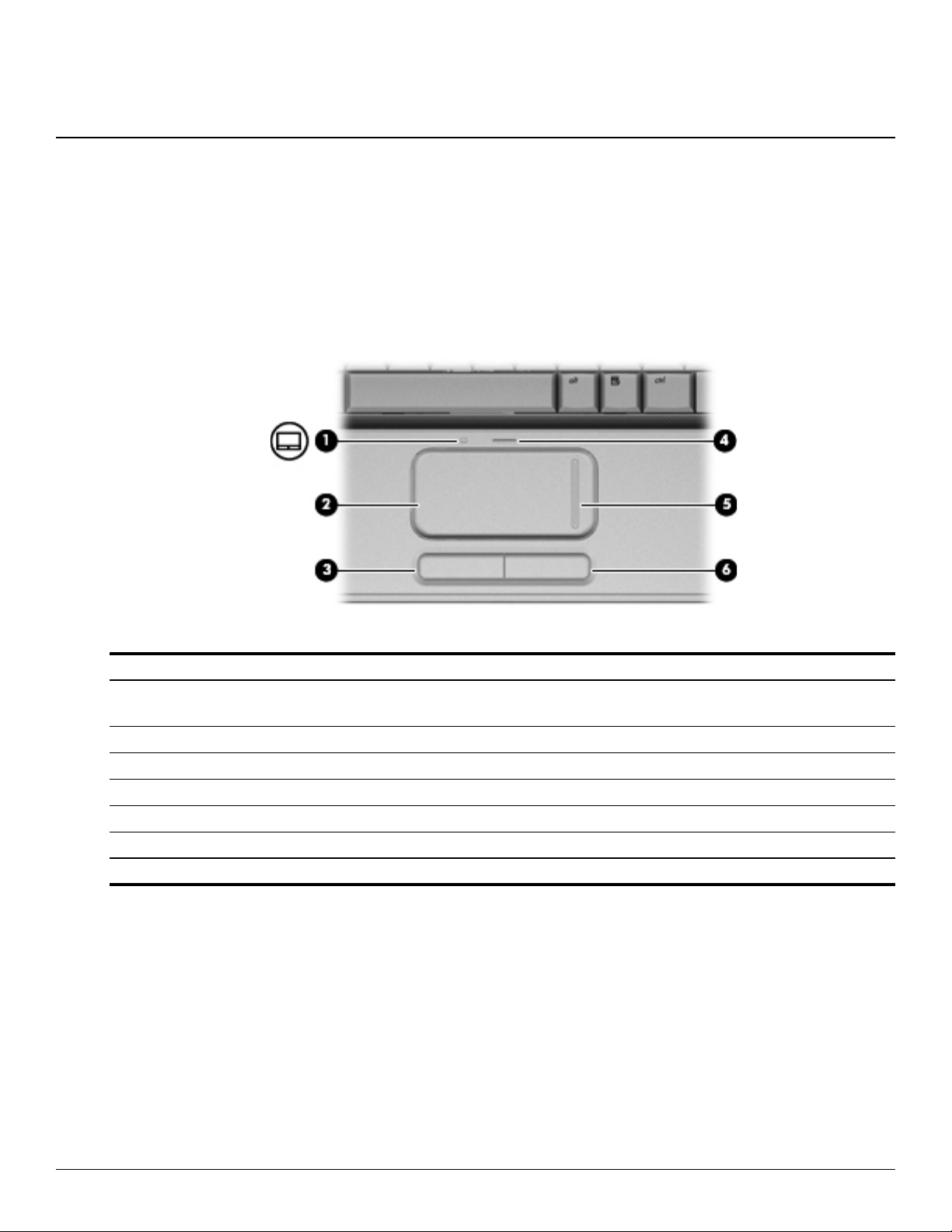
TouchPad
2
External component identification
Item Component Description
1 TouchPad light White—TouchPad is enabled.
Amber—TouchPad is disabled.
2 TouchPad* Moves the pointer and selects or activates items on the screen.
3 Left TouchPad button* Functions like the left button on an external mouse.
4 TouchPad On/Off button Enables/disables the TouchPad.
5 TouchPad vertical scroll zone Scrolls up or down.
6 Right TouchPad button* Functions like the right button on an external mouse.
*This table describes factory settings.
To view or change the pointing device preferences:
1. Select Start > Devices and Printers.
2. Right-click the device representing your computer.
3. Select Mouse settings.
Maintenance and Service Guide 2–1
Page 13
External component identification
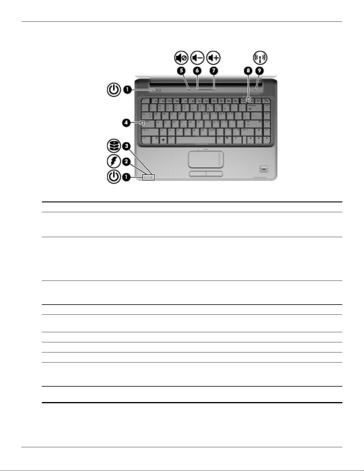
Lights
Item Component Description
1 Power lights (2)* On—The computer is on.
Flashing—The computer is in Sleep.
Off—The computer is off or in Hibernation.
2 Battery light On—The battery is charging.
Flashing—The battery reaches a low battery level or a critical battery level.
Off—If the computer is connected to an external power source, the light is off
when all batteries in the computer are fully charged. If the computer is not
connected to an external power source, the light is off until the battery
reaches a low battery level.
3 Drive light Flashing—The hard drive or the optical drive is being accessed.
On—HP ProtectSmart Hard Drive Protection has temporarily parked the
internal hard drive, and if present, the hard drive in the SmartBay.
4 Caps lock light On—The caps lock is on.
5 Volume Mute light White—The computer sound is on.
Amber—The computer sound is off.
6 Volume Down light On—Decreases speaker volume.
7 Volume Up light On—Increases speaker volume.
8 Num lock light On—The num lock is on or the embedded numeric keypad is enabled.
9 Wireless light Blue—An integrated wireless device, such as a wireless local area network
(WLAN) device and/or a Bluetooth® device, is on.
Amber—No wireless devices are detected.
*The two Power lights display the same information. The light on the Power button is visible only when the computer is open.
The Power light on the front of the computer is visible whether the computer is open or closed.
2–2 Maintenance and Service Guide
Page 14
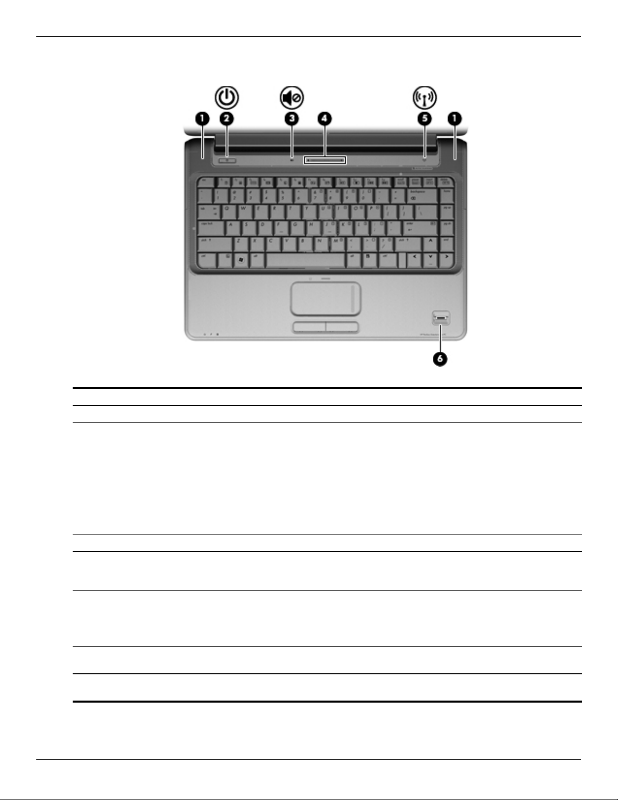
Buttons, speakers, and fingerprint reader
External component identification
Item Component Description
1 Speakers (2) Produce sound.
2 Power button* When the computer is off, press the button to turn on the computer.
When the computer is on, press the button to initiate Sleep.
When the computer is in Sleep, press the button to exit Sleep.
When the computer is in Hibernation, press the button to exit Hibernation.
If the computer has stopped responding and Windows shutdown procedures
are ineffective, press and hold the Power button for at least five seconds to
shut down the computer.
To learn more about power settings, select Start > Control Panel > System
and Security > Power Options.
3 Volume Mute button Mutes and restores speaker sound.
4 Volume Scroll zone Adjusts speaker volume. To decrease volume, slide your finger to the left or
tap the minus sign on the scroll zone. To increase volume, slide your finger to
the right or tap the plus sign on the scroll zone.
5 Wireless button Turns the wireless feature on or off but does not create a wireless
connection.
A wireless network must be set up in order to establish a wireless
✎
connection.
6 Fingerprint Reader
(select models only)
*This table describes factory settings. For information about changing factory settings, see the user guides located in Help and
Support.
Allows a fingerprint logon to Windows, instead of a password logon.
Maintenance and Service Guide 2–3
Page 15
External component identification
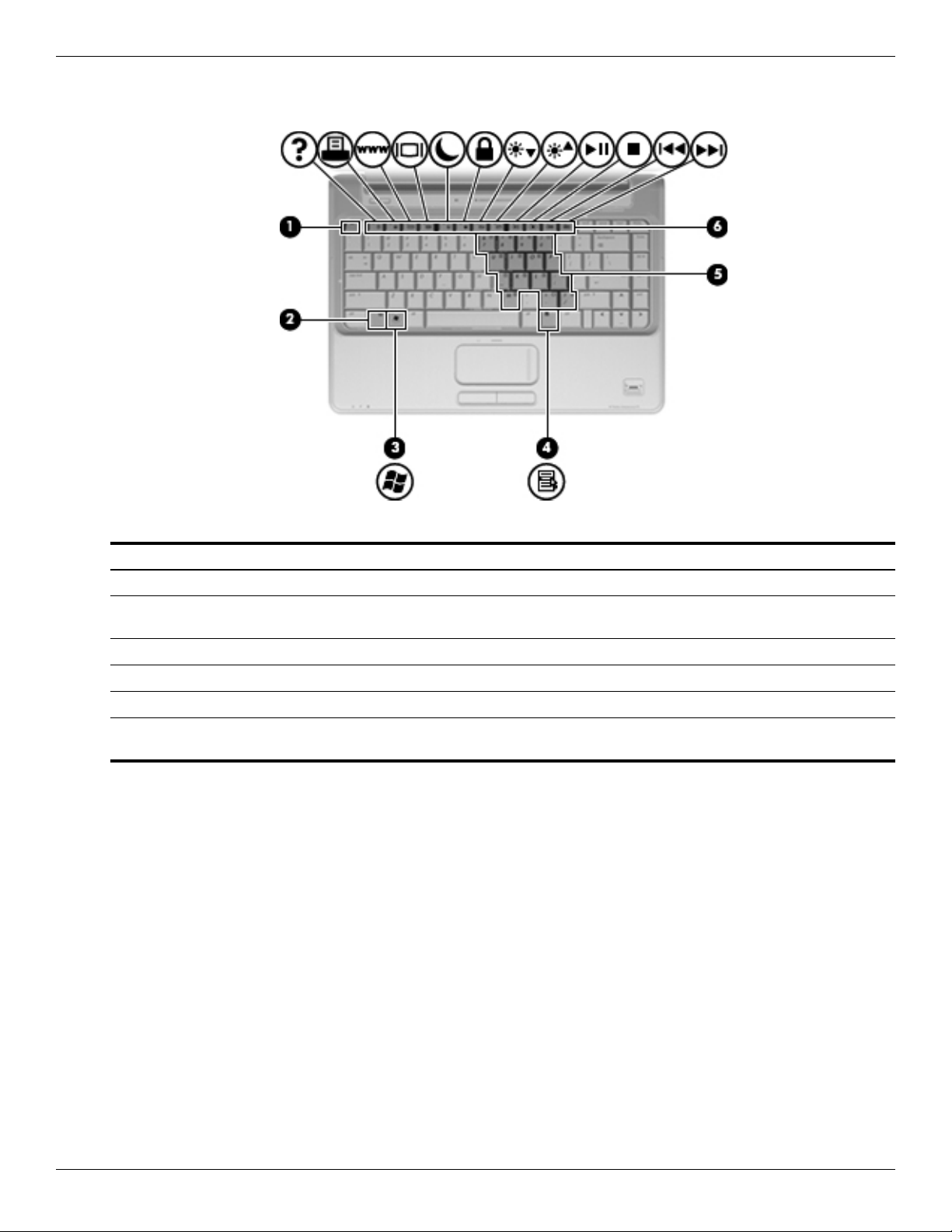
Keys
Item Component Description
1 esc key Displays system information when pressed at the same time as the fn key.
2 fn key Executes frequently used system functions when pressed at the same time as
a function key or the esc key.
3 Windows Logo key Displays the Windows Start menu.
4 Windows Applications key Displays a shortcut menu for items beneath the pointer.
5 Embedded numeric keypad keys Used like the keys on an external numeric keypad.
6 Function keys Executes frequently used system functions when pressed at the same time as
the fn key.
2–4 Maintenance and Service Guide
Page 16
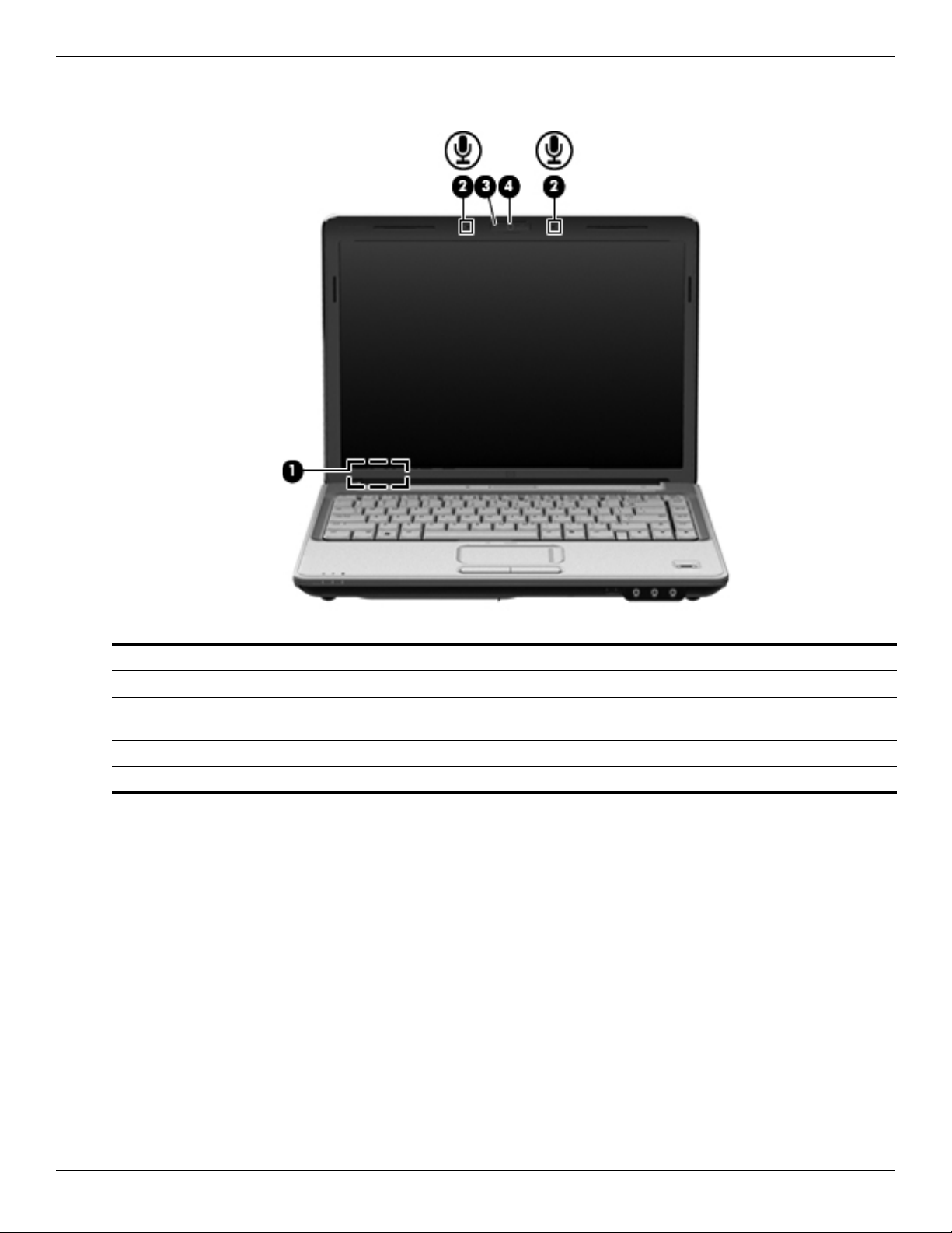
Display
External component identification
Item Component Description
1 Internal display switch Turns off the display if the display is closed while the computer is on.
2 Internal digital dual-array
microphones
3 Webcam light On—The webcam is in use.
4 Webcam Records video and captures still photographs.
(2)
Records sound.
Maintenance and Service Guide 2–5
Page 17
External component identification
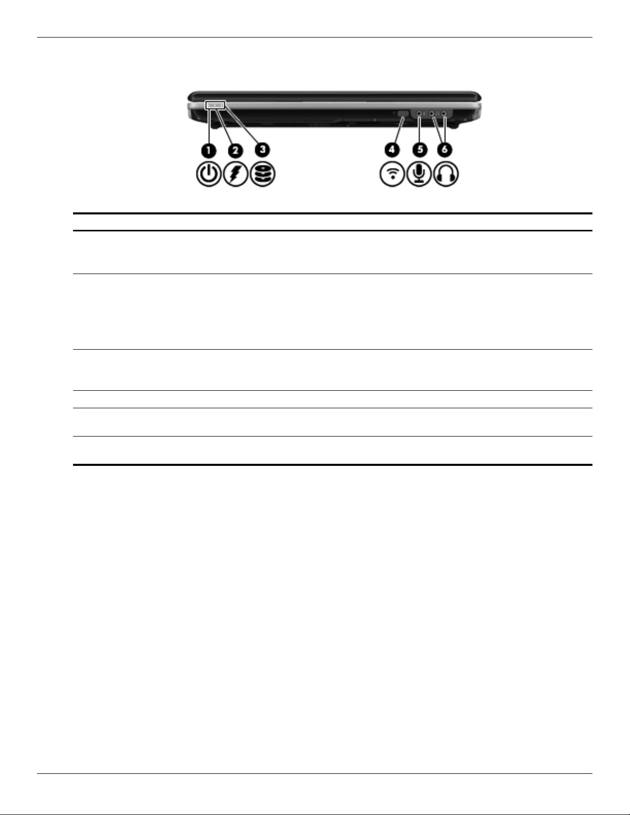
Front components
Item Component Description
1 Power light On—The computer is on.
2 Battery light On—The battery is charging.
3 Drive light Flashing—The hard drive or the optical drive is being accessed.
Flashing—The computer is in Sleep.
Off—The computer is off or in Hibernation.
Flashing—The battery reaches a low battery level or a critical battery level.
Off—If the computer is connected to an external power source, the light is off
when all batteries in the computer are fully charged. If the computer is not
connected to an external power source, the light is off until the battery
reaches a low battery level.
On—The HP ProtectSmart Hard Drive Protection has temporarily parked the
internal hard drive, and if present, the hard drive in the SmartBay.
4 Consumer infrared lens Receives a signal from the HP Remote Control.
5 Audio-in (microphone) jack Connects an optional computer headset microphone, stereo array
microphone, or monaural microphone.
6 Audio-out (headphone) jacks (2) Produces sound when connected to optional powered stereo speakers,
headphones, ear buds, headsets, or television audio.
2–6 Maintenance and Service Guide
Page 18

Rear component
Component Description
Vent Enables airflow to cool internal components.
External component identification
The computer fan starts automatically to cool internal components and
✎
prevent overheating. It is normal for the internal fan to cycle on and off
during routine operation.
Maintenance and Service Guide 2–7
Page 19
External component identification
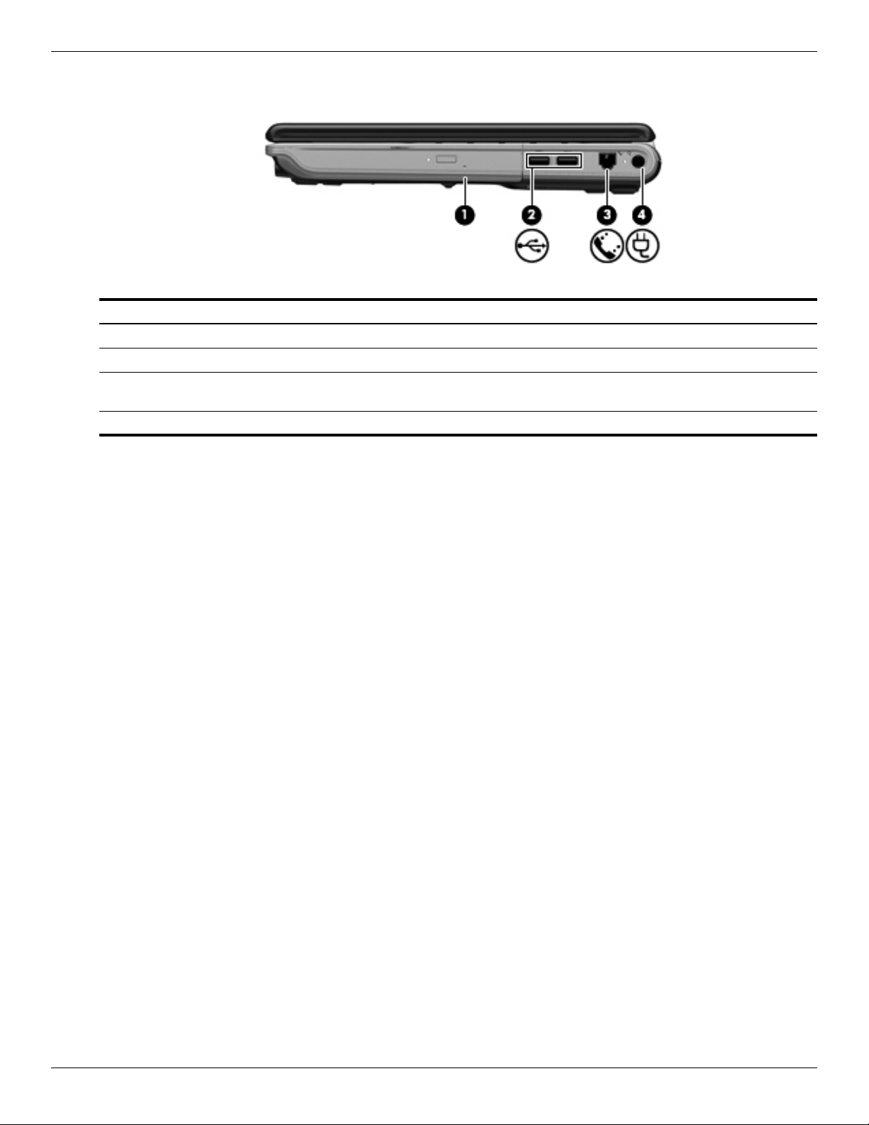
Right-side components
Item Component Description
1 SmartBay Supports an optical drive or hard drive.
2 USB ports (2) Connects optional USB devices.
3 RJ-11 (modem) jack
(select models only)
4 Power connector Connects an AC adapter.
Connects a modem cable.
2–8 Maintenance and Service Guide
Page 20
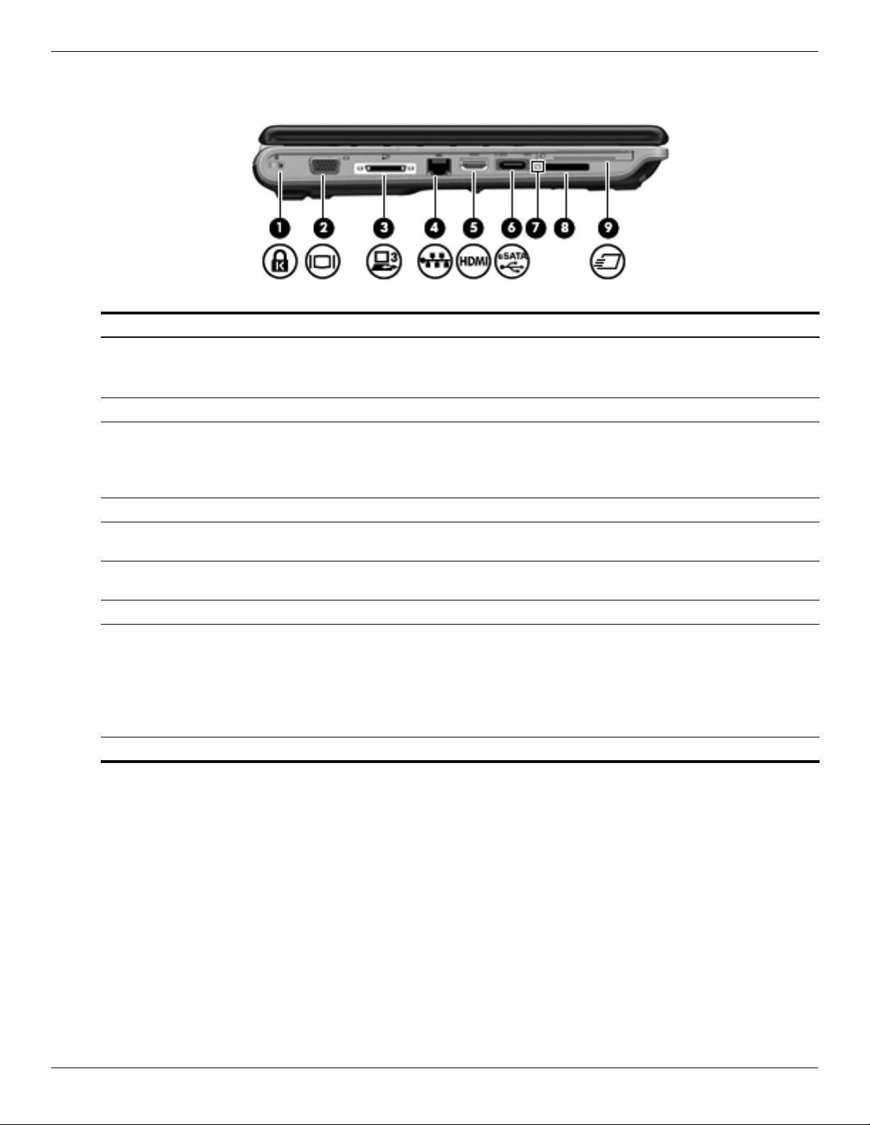
Left-side components
Item Component Description
1 Security Cable slot Attaches an optional security cable to the computer.
2 External Monitor port Connects an external VGA monitor or projector.
3 Expansion port 3 Connects the computer to an optional docking device or optional expansion
4 RJ-45 (network) jack Connects a network cable.
External component identification
The security cable is designed to act as a deterrent, but it might not
✎
prevent the computer from being mishandled or stolen.
product.
The computer has only one expansion port. The term expansion port 3
✎
describes the type of expansion port.
5 HDMI port Connects an optional video or audio device, such as a high-definition
television, or any compatible digital or audio component.
6 eSATA/USB port Connects high-performance eSATA components, such as an eSATA external
hard drive, or connects an optional USB device.
7 Digital Media Slot light On—Accessing a digital card.
8 Digital Media Slot Supports the following optional digital card formats:
Memory Stick (MS)
Memory Stick Pro (MSP)
MultiMediaCard (MMC)
Secure Digital (SD) Memory Card
xD-Picture Card (XD)
9 ExpressCard slot Supports optional ExpressCard/54 cards.
Maintenance and Service Guide 2–9
Page 21
External component identification
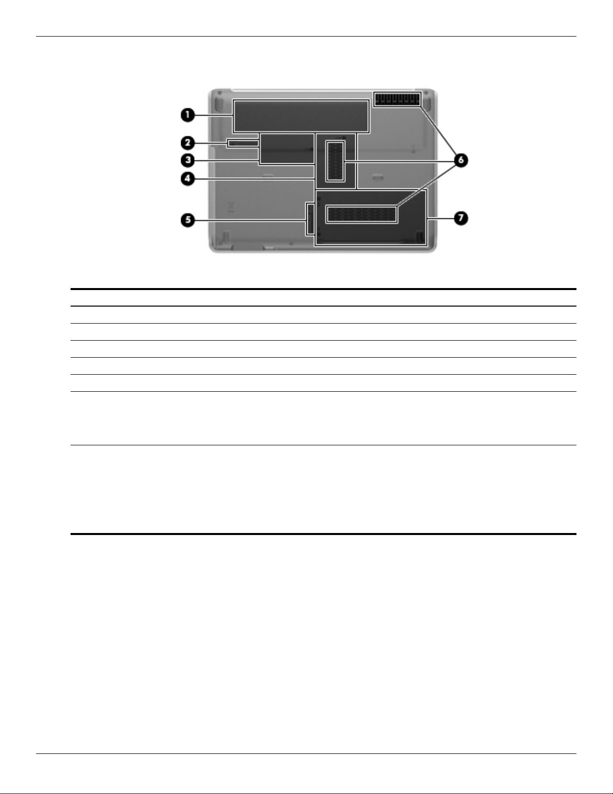
Bottom components
Item Component Description
1 Battery bay Holds the battery.
2 Battery Release latch Releases the battery from the battery bay.
3 Mini Card compartment Contains the RTC battery.
4 Memory Module compartment Contains the two memory module slots.
5 SmartBay Release latch Releases the SmartBay module.
6 Vents (3) Enables airflow to cool internal components.
The computer fan starts automatically to cool internal components and
✎
prevent overheating. It is normal for the internal fan to cycle on and off
during routine operation.
7 Hard Drive bay Holds the hard drive and the wireless LAN (WLAN) device.
To prevent an unresponsive system, replace the wireless module only
Ä
with a wireless module authorized for use in the computer by the
governmental agency that regulates wireless devices in your country or
region. If you replace the module and then receive a warning message,
remove the module to restore computer functionality, and then contact
technical support through Help and Support.
2–10 Maintenance and Service Guide
Page 22
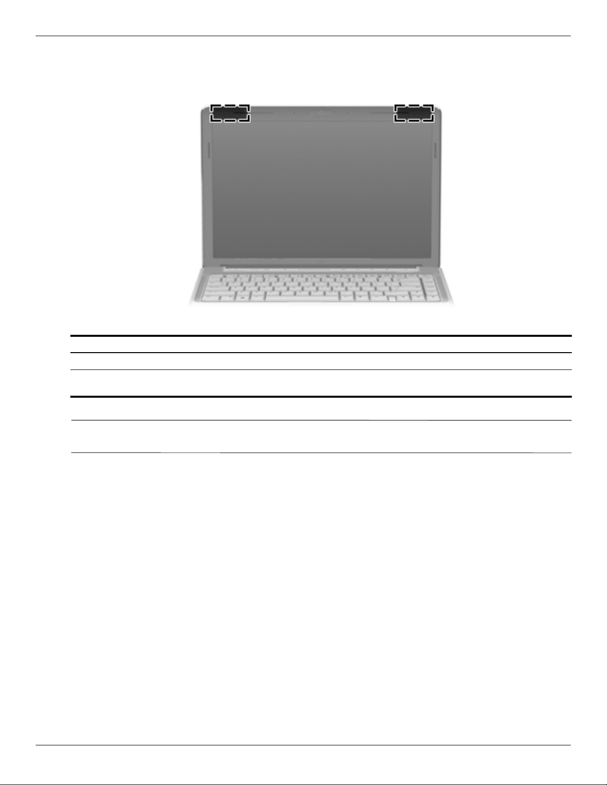
Wireless antennas
External component identification
Component Description
WLAN antennas (2)* Send and receive wireless signals to communicate with wireless networks.
*The antennas are not visible from the outside of the computer. For optimal transmission, keep the areas immediately around
the antennas free from obstructions.
To review wireless regulatory notices, see the country-specific section of Regulatory, Safety and Environmental
✎
Notices chapter in Help and Support.
Maintenance and Service Guide 2–11
Page 23
External component identification
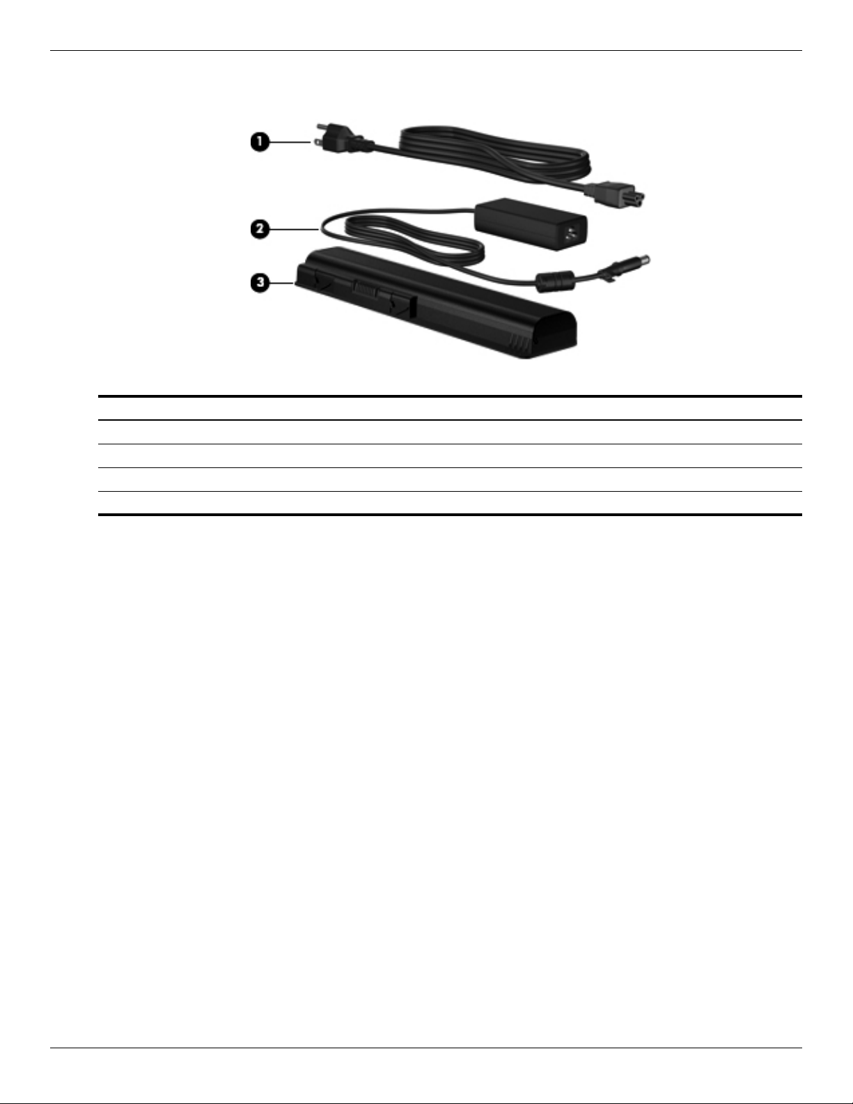
Additional hardware components
Item Component Description
1 Power cord* Connects an AC adapter to an AC outlet.
2 AC adapter Converts AC power to DC power.
3 Battery* Powers the computer when the computer is not connected to external power.
*Batteries and power cords vary in appearance by country or region.
2–12 Maintenance and Service Guide
Page 24
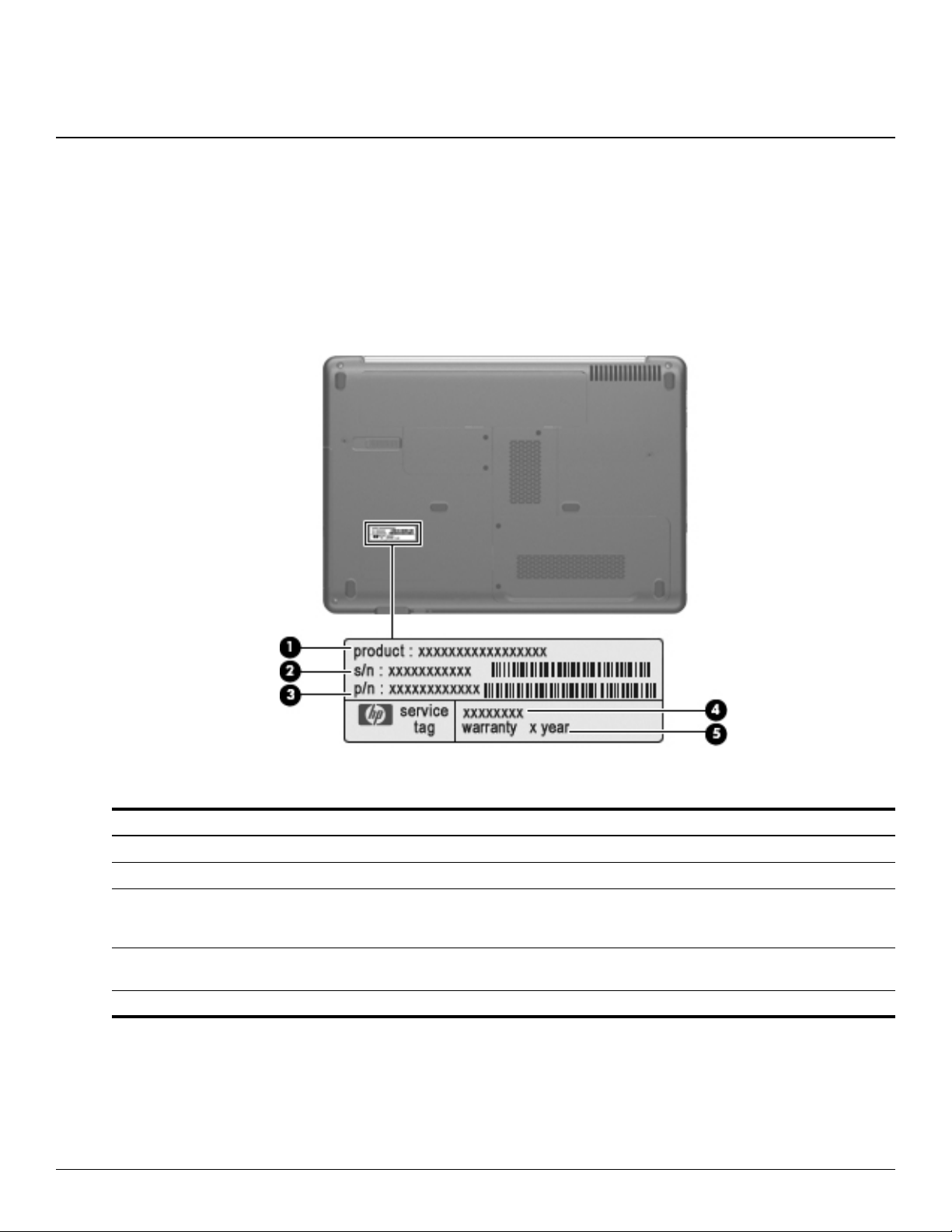
Service tag
When ordering parts or requesting information, provide the computer serial number and model description
provided on the service tag.
3
Illustrated parts catalog
Item Component Description
1 Product name The name affixed to the front of the computer.
2 Serial number (s/n) An alphanumeric identifier that is unique to each product.
3 Part number/Product number (p/n) This number provides specific information about the product’s hardware
components. The part number helps a service technician to determine which
components and parts are needed.
4 Model description An alphanumeric identifier used to locate documents, drivers, and support for
the computer.
5 Warranty period The duration of the warranty period for the computer.
Maintenance and Service Guide 3–1
Page 25
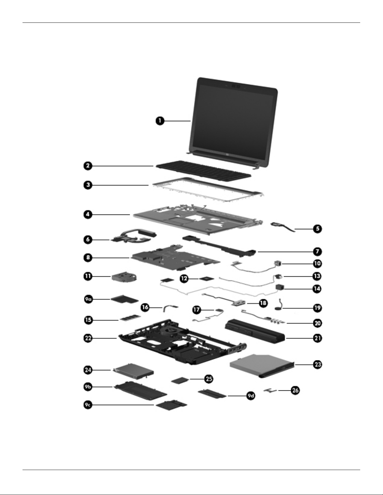
Illustrated parts catalog
Computer major components
3–2 Maintenance and Service Guide
Page 26

Illustrated parts catalog
Item Description Spare part number
1 Display assembly (see “Display assembly subcomponents” on page 3-9)
14.1-in WXGA BrightView display assembly for use with black computer models 594110-001
14.1-in WXGA BrightView display assembly with wireless mobile broadband for use with
black computer models
14.1-in WXGA BrightView display assembly for use with white computer models 594111-001
14.1-in WXGA BrightView display assembly with wireless mobile broadband for use with
white computer models
14.1-in WXGA BrightView display assembly for use with plaid computer models 594112-001
14.1-in WXGA BrightView display assembly with wireless mobile broadband for use with
plaid computer models
2 Keyboard (includes keyboard cable)
For use with black computer models in:
Brazil 518793-201
French Canada 518787-121
Japan 518793-291
Latin America 518793-161
South Korea 518793-AD1
Ta iw a n 518793-AB1
Thailand 518793-281
the United States 518793-001
For use with black computer models (textured) in:
Brazil 570755-201
594110-002
594111-002
594112-002
French Canada 570755-121
Japan 570755-291
Latin America 570755-161
South Korea 570755-AD1
Ta iw a n 570755-AB1
Thailand 570755-281
the United States 570755-001
For use with white computer models in:
Brazil 538108-201
French Canada 518792-121
Japan 538108-291
Latin America 538108-161
South Korea 538108-AD1
Ta iw a n 538108-AB1
Thailand 538108-281
the United States 538108-001
3 Keyboard cover
(Continued)
Maintenance and Service Guide 3–3
Page 27

Illustrated parts catalog
Item Description Spare part number
Black computer models 539729-001
White computer models 539728-001
Plaid computer models 594532-001
4 Top cover (includes TouchPad board and cable)
Black computer models equipped with a Fingerprint Reader 591953-001
Black computer models not equipped with a Fingerprint Reader 591952-001
White computer models equipped with a Fingerprint Reader 591951-001
White computer models not equipped with a Fingerprint Reader 591950-001
Plaid computer models equipped with a Fingerprint Reader 591955-001
Plaid computer models not equipped with a Fingerprint Reader 591954-001
TouchPad button board (includes cable) 486832-001
TouchPad bracket 494961-001
5 Fingerprint Reader board (includes cable) 486828-001
6 Heat sink assembly (includes replacement thermal material)
UMA graphics subsystems 591957-001
Discrete graphics subsystems 591956-001
7 Speaker assembly
All countries and regions except India 486837-001
India 486865-D61
8 System board (includes replacement thermal material)
UMA graphics subsystems 590350-001
Discrete graphics subsystems 590349-001
Plastics Kit (see “Plastics Kit” on page 3-10 for spare part component information) 486833-001
9a ExpressCard slot bezel
9b Hard Drive compartment cover
9c Memory Module compartment cover
9d Mini Card compartment cover
10 Modem module (select models only)
All countries and regions except for Australia and New Zealand 461749-001
Australia and New Zealand 461749-011
Modem module cable (includes RJ-11 connector) 494981-001
11 Fan (includes replacement thermal material) 486844-001
12 WLAN module
Broadcom BCM4312 802.11b/g for use in Canada, the Cayman Islands, Guam, Puerto
Rico, the United States, and the U.S. Virgin Islands
504593-003
(Continued)
3–4 Maintenance and Service Guide
Page 28

Illustrated parts catalog
Item Description Spare part number
Broadcom BCM4312 802.11b/g for use in Afghanistan, Albania, Algeria, Andorra, Angola,
Antigua and Barbuda, Argentina, Armenia, Aruba, Australia, Austria, Azerbaijan, the
Bahamas, Bahrain, Bangladesh, Barbados, Belarus, Belgium, Belize, Benin, Bermuda,
Bhutan, Bolivia, Bosnia and Herzegovina, Botswana, Brazil, the British Virgin Islands,
Brunei, Bulgaria, Burkina Faso, Burundi, Cambodia, Cameroon, Cape Verde, the Central
African Republic, Chad, Colombia, Comoros, the Congo, Costa Rica, Croatia, Cyprus, the
Czech Republic, Denmark, Djibouti, Dominica, the Dominican Republic, East Timor,
Ecuador, Egypt, El Salvador, Equitorial Guinea, Eritrea, Estonia, Ethiopia, Fiji, Finland,
France, French Guiana, Gabon, Gambia, Georgia, Germany, Ghana, Gibraltar, Greece,
Grenada, Guadeloupe, Guatemala, Guinea, Guinea-Bissau, Guyana, Haiti, Honduras,
Hong Kong, Hungary, Iceland, India, Indonesia, Ireland, Israel, Italy, the Ivory Coast,
Jamaica, Japan, Jordan, Kazakhstan, Kenya, Kiribati, Kuwait, Kyrgyzstan, Laos, Latvia,
Lebanon, Lesotho, Liberia, Liechtenstein, Lithuania, Luxembourg, Macedonia, Madagascar,
Malawi, Malaysia, the Maldives, Mali, Malta, the Marshall Islands, Martinique, Mauritania,
Mauritius, Mexico, Micronesia, Monaco, Mongolia, Montenegro, Morocco, Mozambique,
Namibia, Nauru, Nepal, the Nether Antilles, the Netherlands, New Zealand, Nicaragua,
Niger, Nigeria, Norway, Oman, Pakistan, Palau, Panama, Papua New Guinea, Paraguay, the
People's Republic of China, Peru, the Philippines, Poland, Portugal, Qatar, the Republic of
Moldova, Romania, Russia, Rwanda, Samoa, San Marino, Sao Tome and Principe, Saudi
Arabia, Senegal, Serbia, the Seychelles, Sierra Leone, Singapore, Slovakia, Slovenia, the
Solomon Islands, Somalia, South Africa, South Korea, Spain, Sri Lanka, St. Kitts and Nevis,
St. Lucia, St. Vincent and the Grenadines, Suriname, Swaziland, Sweden, Switzerland,
Syria, Taiwan, Tajikistan, Tanzania, Thailand, Togo, Tonga, Trinidad and Tobago, Tunisia,
Turkey, Turkmenistan, Tuvalu, Uganda, Ukraine, the United Arab Emirates, the United
Kingdom, Uruguay, Uzbekistan, Vanuatu, Venezuela, Vietnam, Yemen, Zaire, Zambia, and
Zimbabwe
Atheros AR9285 802.11b/g/n for use in Canada, the Cayman Islands, Guam, Puerto Rico,
the United States, and the U.S. Virgin Islands
504593-004
518436-001
(Continued)
Maintenance and Service Guide 3–5
Page 29

Illustrated parts catalog
Item Description Spare part number
WLAN module, Continued
Atheros AR9285 802.11b/g/n for use in Afghanistan, Albania, Algeria, Andorra, Angola,
Antigua and Barbuda, Argentina, Armenia, Aruba, Australia, Austria, Azerbaijan, the
Bahamas, Bahrain, Barbados, Belgium, Belize, Benin, Bermuda, Bhutan, Bosnia and
Herzegovina, Botswana, Brazil, the British Virgin Islands, Brunei, Bulgaria, Burkina Faso,
Burundi, Cambodia, Cameroon, Cape Verde, the Central African Republic, Chad, Chile,
Colombia, Comoros, the Congo, Costa Rica, Croatia, Cyprus, the Czech Republic,
Denmark, Djibouti, Dominica, the Dominican Republic, East Timor, Ecuador, Egypt, El
Salvador, Equatorial Guinea, Eritrea, Estonia, Ethiopia, Fiji, Finland, France, French
Guiana, Gabon, Gambia, Georgia, Germany, Ghana, Gibraltar, Greece, Grenada,
Guadeloupe, Guatemala, Guinea, Guinea-Bissau, Guyana, Haiti, Honduras, Hong Kong,
Hungary, Iceland, India, Indonesia, Ireland, Italy, the Ivory Coast, Jamaica, Japan, Jordan,
Kazakhstan, Kenya, Kiribati, Kuwait, Kyrgyzstan, Laos, Latvia, Lebanon, Lesotho, Liberia,
Liechtenstein, Lithuania, Luxembourg, Macedonia, Madagascar, Malawi, Malaysia, the
Maldives, Mali, Malta, the Marshall Islands, Martinique, Mauritania, Mauritius, Mexico,
Micronesia, Monaco, Mongolia, Montenegro, Morocco, Mozambique, Namibia, Nauru,
Nepal, the Nether Antilles, the Netherlands, New Zealand, Nicaragua, Niger, Nigeria,
Norway, Oman, Palau, Panama, Papua New Guinea, Paraguay, the People's Republic of
China, Peru, the Philippines, Poland, Portugal, the Republic of Moldova, Romania, Rwanda,
Samoa, San Marino, Sao Tome and Principe, Saudi Arabia, Senegal, Serbia, the
Seychelles, Sierra Leone, Singapore, Slovakia, Slovenia, the Solomon Islands, Somalia,
South Africa, South Korea, Spain, Sri Lanka, St. Kitts and Nevis, St. Lucia, St. Vincent and
the Grenadines, Suriname, Swaziland, Sweden, Switzerland, Syria, Taiwan, Tajikistan,
Tanzania, Thailand, Togo, Tonga, Trinidad and Tobago, Tunisia, Turkey, Turkmenistan,
Tuvalu, Uganda, the United Arab Emirates, the United Kingdom, Uruguay, Uzbekistan,
Vanuatu, Venezuela, Vietnam, Yemen, Zaire, Zambia, and Zimbabwe
518436-002
(Continued)
3–6 Maintenance and Service Guide
Page 30

Illustrated parts catalog
Item Description Spare part number
WLAN module, Continued
Atheros AR5009 802.11a/b/g/n for use in Canada, the Cayman Islands, Guam, Puerto Rico,
the United States, and the U.S. Virgin Islands
Atheros AR5009 802.11a/b/g/n for use in Afghanistan, Albania, Algeria, Andorra, Angola,
Antigua and Barbuda, Argentina, Armenia, Aruba, Australia, Austria, Azerbaijan, the
Bahamas, Bahrain, Barbados, Belgium, Belize, Benin, Bermuda, Bhutan, Bosnia and
Herzegovina, Botswana, Brazil, the British Virgin Islands, Brunei, Bulgaria, Burkina Faso,
Burundi, Cambodia, Cameroon, Cape Verde, the Central African Republic, Chad, Chile,
Colombia, Comoros, the Congo, Costa Rica, Croatia, Cyprus, the Czech Republic,
Denmark, Djibouti, Dominica, the Dominican Republic, East Timor, Ecuador, Egypt, El
Salvador, Equatorial Guinea, Eritrea, Estonia, Ethiopia, Fiji, Finland, France, French
Guiana, Gabon, Gambia, Georgia, Germany, Ghana, Gibraltar, Greece, Grenada,
Guadeloupe, Guatemala, Guinea, Guinea-Bissau, Guyana, Haiti, Honduras, Hong Kong,
Hungary, Iceland, India, Indonesia, Ireland, Israel, Italy, the Ivory Coast, Jamaica, Japan,
Jordan, Kazakhstan, Kenya, Kiribati, Kuwait, Kyrgyzstan, Laos, Latvia, Lebanon, Lesotho,
Liberia, Liechtenstein, Lithuania, Luxembourg, Macedonia, Madagascar, Malawi, Malaysia,
the Maldives, Mali, Malta, the Marshall Islands, Martinique, Mauritania, Mauritius, Mexico,
Micronesia, Monaco, Mongolia, Montenegro, Morocco, Mozambique, Namibia, Nauru,
Nepal, the Nether Antilles, the Netherlands, New Zealand, Nicaragua, Niger, Nigeria,
Norway, Oman, Palau, Panama, Papua New Guinea, Paraguay, the People's Republic of
China, Peru, the Philippines, Poland, Portugal, the Republic of Moldova, Romania, Rwanda,
Samoa, San Marino, Sao Tome and Principe, Saudi Arabia, Senegal, Serbia, the
Seychelles, Sierra Leone, Singapore, Slovakia, Slovenia, the Solomon Islands, Somalia,
South Africa, South Korea, Spain, Sri Lanka, St. Kitts and Nevis, St. Lucia, St. Vincent and
the Grenadines, Suriname, Swaziland, Sweden, Switzerland, Syria, Taiwan, Tajikistan,
Tanzania, Thailand, Togo, Tonga, Trinidad and Tobago, Tunisia, Turkey, Turkmenistan,
Tuvalu, Uganda, the United Arab Emirates, the United Kingdom, Uruguay, Uzbekistan,
Vanuatu, Venezuela, Vietnam, Yemen, Zaire, Zambia, and Zimbabwe
13 ATSC/NTSC TV tuner 482899-001
14 Power connector (includes cable) 486836-001
518437-001
518437-002
(Continued)
Maintenance and Service Guide 3–7
Page 31

Illustrated parts catalog
Item Description Spare part number
15 Memory module (1066 MHz, DDR3)
1024 MB 590351-001
2048 MB 590352-001
4096 MB 590353-001
16 Power button board (includes cable) 486853-001
17 Bluetooth module (select models only) 537921-001
Bluetooth module cable (select models only)
UMA graphics subsystems 486847-001
Discrete graphics subsystems 488130-001
18 USB board 486842-001
USB board cable 486843-001
19 RTC battery 486835-001
20 Audio board 486840-001
Audio board cable 486841-001
21 Battery
12-cell Li-Ion (2.2 Ah, 95 Wh) 484172-001
6-cell Li-Ion (2.55 Ah, 55 Wh) 484171-001
6-cell Li-Ion (2.2 Ah, 47 Wh) 484170-001
3-cell Li-Ion (4.4 Ah, 47 Wh) 516915-001
22 Base enclosure 486848-001
23 Optical drive (includes bezel and bracket)
DVD±R/RW SuperMulti DL Drive with LightScribe 482177-001
Blu-ray ROM DVD±R/RW SuperMulti DL Drive with LightScribe 508123-001
24 Hard Drive (includes hard drive bracket) (for hard drive spare part component information see “Mass storage
devices” on page 3-11 for hard drive spare part component information)
25 Processor (includes replacement thermal material):
Intel Arrandale CPU-uPGA Single-Core i5-520M (2.4 GHz, 3-MB L3 cache, 1066 MHZ SC
Turbo)
Intel Arrandale CPU-uPGA Single-Core i5-540M (2.53 GHz, 3-MB L3 cache, 1066 MHZ SC
Turbo)
26 Mini Card bracket 577509-001
594187-001
594188-001
3–8 Maintenance and Service Guide
Page 32

Display assembly subcomponents
Illustrated parts catalog
Item Description Spare part number
1 Display bezel 573197-001
2 Webcam/microphone module 573195-001
3 14.1-in WXGA BrightView display panel 483261-001
4 Display hinge kit 486894-001
5 Display inverter 486736-001
6a Display cable 486878-001
6b Wireless antenna 594105-001
Wireless antenna cables 489068-001
7 Display enclosure (includes logo light and cables)
Black computer models 518799-001
White computer models 518825-001
Plaid computer models 573188-001
Display Rubber Kit* (contains all rubber pieces for the display bezel) 486874-001
Internal display switch* 486846-001
* not illustrated
Maintenance and Service Guide 3–9
Page 33

Illustrated parts catalog
Plastics Kit
Item Description Spare part number
Plastics Kit: 486833-001
1 Hard Drive cover (includes two captive screws)
2 Memory Module compartment cover
3 Mini Card compartment cover
4 ExpressCard slot bezel
3–10 Maintenance and Service Guide
Page 34

Mass storage devices
Illustrated parts catalog
Item Description Spare part number
1 Hard Drive (includes hard drive bracket)
500 GB, 7200 rpm 575569-001
320 GB, 7200 rpm 575568-001
250 GB, 7200 rpm 575567-001
160 GB, 7200 rpm 580846-001
Hard Drive Hardware Kit*
Hard Drive Hardware Kit 482158-001
Hard Drive Hardware Kit, MultiBay 488128-001
MultiBay blank* 491876-001
2 Optical drive (includes bezel and bracket)
DVD±R/RW SuperMulti DL Drive with LightScribe 482177-001
Blu-ray ROM DVD±R/RW SuperMulti DL Drive with LightScribe 508123-001
* not illustrated
Maintenance and Service Guide 3–11
Page 35

Illustrated parts catalog
Miscellaneous parts
Description Spare part number
65-W PFC AC Adapter 463958-001
90-W PFC AC Adapter 463955-001
Power cords
Argentina 490371-D01
Australia 490371-011
Brazil 490371-201
Europe 490371-021
India 490371-D61
Italy 490371-061
Japan 490371-291
People’s Republic of China 490371-AA1
South Korea 490371-AD1
Ta iw a n 490371-AB1
United Kingdom and Singapore 490371-031
the United States 490371-001
Rubber Kit (includes computer feet and screw covers) 486834-001
CAT5e network cable 454619-001
Wired headset with volume control 371693-001
Screw Kit (includes all screws)
Phillips PM1.5 × 9.0 screws
Phillips PM2.0 × 2.0 broadhead screws
Phillips PM2.0 × 3.0 screws
Phillips PM2.0 × 4.0 screws
Phillips PM2.0 × 5.0 screws
Phillips PM2.0 × 10.0 captive screws
Phillips PM2.5 × 3.0 screws
Phillips PM2.5 × 4.0 screws
Phillips PM2.5 × 5.0 screws
Phillips PM2.5 × 6.0 captive screws
Phillips PM2.5 × 8.0 screws
Phillips PM2.5 × 15.0 screws
Phillips PM3.0 × 3.0 screws
SIM for models with WWAN 486845-001
TV tuners
486873-001
ATSC/NTSC TV tuner antenna 482900-001
TV tuner antenna with PAL jack 482900-002
ATSC/NTSC TV tuner 482899-001
DVB-T/ANG Integrated TV tuner 482899-002
DVB-T tuner 482899-003
(Continued)
3–12 Maintenance and Service Guide
Page 36

Illustrated parts catalog
Description Spare part number
DVB-T tuner for use only in the AP region 482899-004
Optical wired mouse 436238-001
Wireless laser mouse 430958-001
Remote Controls
ExpressCard remote control 464793-002
Full function remote control 465540-001
Full function remote control for use with blue-colored computer models 465540-002
Full function remote control with Teletext 465541-001
Full function remote control with Teletext for use with blue-colored computer models 465541-002
Standard carrying case 418162-001
Maintenance and Service Guide 3–13
Page 37

Illustrated parts catalog
Sequential part number listing
Spare part number Description
371693-001 Wired headset with volume control
418162-001 Standard carrying case
430958-001 Wireless laser mouse
436238-001 Optical wired mouse
454619-001 CAT5e network cable
461749-001 Modem module for use in all countries and regions except for Australia and New Zealand
4461749-011 Modem module for use in Australia and New Zealand
463955-001 90-W PFC AC Adapter
463958-001 65-W PFC AC Adapter
464793-002 ExpressCard remote control
465540-001 Full function remote control
465540-002 Full function remote control for use with blue-colored computer models
465541-001 Full function remote control with Teletext
465541-002 Full function remote control with Teletext for use with blue-colored computer models
482158-001 Hard Drive Hardware Kit
482177-001 DVD±R/RW SuperMulti DL Drive with LightScribe
482899-001 ATSC/NTSC TV tuner
482899-002 DVB-T/ANG Integrated TV tuner
482899-003 DVB-T tuner
482899-004 DVB-T tuner for use only in the AP region
482900-001 ATSC/NTSC TV tuner antenna
482900-002 TV tuner antenna with PAL jack
483261-001 14.1-in WXGA BrightView display panel
484170-001 6-cell Li-lon (2.2 Ah, 47 Wh)
484171-001 6-cell Li-lon, (2.55 Ah, 55 Wh)
484172-001 12-cell Li-Ion (2.2 Ah, 95 Wh)
486736-001 Display inverter
486828-001 Fingerprint Reader and cable
486832-001 TouchPad button board (includes cable)
486833-001 Plastics Kit
486834-001 Rubber Kit (includes computer feet and screw covers)
486835-001 RTC battery
486836-001 Power connector and cable
486837-001 Speaker assembly for use in all countries and regions except India
486840-001 Audio board
486841-001 Audio board cable
(Continued)
3–14 Maintenance and Service Guide
Page 38

Illustrated parts catalog
Spare part number Description
486842-001 USB board
486843-001 USB board cable
486844-001 Fan (includes replacement thermal material)
486845-001 SIM for models with WWAN
486846-001 Internal display switch
486847-001 Bluetooth module cable for use only in computer models with UMA graphics subsystems
486848-001 Base enclosure
486853-001 Power button board (includes cable)
486865-D61 Speaker assembly for use India
486873-001 Screw Kit (includes all screws)
486874-001 Display Rubber Kit (contains all rubber pieces for the display bezel)
486878-001 Display cable
486894-001 Display Hinge Kit
488128-001 Hard Drive Hardware Kit, MultiBay
488130-001 Bluetooth module cable for use only in computer models with discrete graphics subsystems
489068-001 Wireless antenna cables
490371-001 Power cord for use in the United States
490371-011 Power cord for use in Australia
490371-021 Power cord for use in Europe
490371-031 Power cord for use in the United Kingdom and Singapore
490371-061 Power cord for use in Italy
490371-201 Power cord for use in Brazil
490371-291 Power cord for use in Japan
490371-AA1 Power cord for use in People’s Republic of China
490371-AB1 Power cord for use in Taiwan
490371-AD1 Power cord for use in South Korea
490371-D01 Power cord for use in Argentina
490371-D61 Power cord for use in India
491876-001 MultiBay blank
494961-001 TouchPad bracket
494981-001 Modem module cable (includes RJ-11 connector)
504593-003 Broadcom BCM4312 802.11b/g WLAN module for use in Canada, the Cayman Islands, Guam,
Puerto Rico, the United States, and the U.S. Virgin Islands
(Continued)
Maintenance and Service Guide 3–15
Page 39

Illustrated parts catalog
Spare part number Description
504593-004 Broadcom BCM4312 802.11b/g for use in Afghanistan, Albania, Algeria, Andorra, Angola, Antigua
508123-001 Blu-ray ROM DVD±R/RW SuperMulti DL Drive with LightScribe
and Barbuda, Argentina, Armenia, Aruba, Australia, Austria, Azerbaijan, the Bahamas, Bahrain,
Bangladesh, Barbados, Belarus, Belgium, Belize, Benin, Bermuda, Bhutan, Bolivia, Bosnia and
Herzegovina, Botswana, Brazil, the British Virgin Islands, Brunei, Bulgaria, Burkina Faso, Burundi,
Cambodia, Cameroon, Cape Verde, the Central African Republic, Chad, Colombia, Comoros, the
Congo, Costa Rica, Croatia, Cyprus, the Czech Republic, Denmark, Djibouti, Dominica, the
Dominican Republic, East Timor, Ecuador, Egypt, El Salvador, Equitorial Guinea, Eritrea, Estonia,
Ethiopia, Fiji, Finland, France, French Guiana, Gabon, Gambia, Georgia, Germany, Ghana, Gibraltar,
Greece, Grenada, Guadeloupe, Guatemala, Guinea, Guinea-Bissau, Guyana, Haiti, Honduras,
Hong Kong, Hungary, Iceland, India, Indonesia, Ireland, Israel, Italy, the Ivory Coast, Jamaica,
Japan, Jordan, Kazakhstan, Kenya, Kiribati, Kuwait, Kyrgyzstan, Laos, Latvia, Lebanon, Lesotho,
Liberia, Liechtenstein, Lithuania, Luxembourg, Macedonia, Madagascar, Malawi, Malaysia, the
Maldives, Mali, Malta, the Marshall Islands, Martinique, Mauritania, Mauritius, Mexico, Micronesia,
Monaco, Mongolia, Montenegro, Morocco, Mozambique, Namibia, Nauru, Nepal, the Nether Antilles,
the Netherlands, New Zealand, Nicaragua, Niger, Nigeria, Norway, Oman, Pakistan, Palau, Panama,
Papua New Guinea, Paraguay, the People's Republic of China, Peru, the Philippines, Poland,
Portugal, Qatar, the Republic of Moldova, Romania, Russia, Rwanda, Samoa, San Marino, Sao
Tome and Principe, Saudi Arabia, Senegal, Serbia, the Seychelles, Sierra Leone, Singapore,
Slovakia, Slovenia, the Solomon Islands, Somalia, South Africa, South Korea, Spain, Sri Lanka, St.
Kitts and Nevis, St. Lucia, St. Vincent and the Grenadines, Suriname, Swaziland, Sweden,
Switzerland, Syria, Taiwan, Tajikistan, Tanzania, Thailand, Togo, Tonga, Trinidad and Tobago,
Tunisia, Turkey, Turkmenistan, Tuvalu, Uganda, Ukraine, the United Arab Emirates, the United
Kingdom, Uruguay, Uzbekistan, Vanuatu, Venezuela, Vietnam, Yemen, Zaire, Zambia, and
Zimbabwe
516915-001 3-cell Li-Ion (4.4 Ah, 47 Wh)
518436-001 Atheros AR9285 802.11b/g/n for use in Canada, the Cayman Islands, Guam, Puerto Rico, the United
States, and the U.S. Virgin Islands
518436-002 Atheros AR9285 802.11b/g/n for use in Afghanistan, Albania, Algeria, Andorra, Angola, Antigua and
Barbuda, Argentina, Armenia, Aruba, Australia, Austria, Azerbaijan, the Bahamas, Bahrain,
Barbados, Belgium, Belize, Benin, Bermuda, Bhutan, Bosnia and Herzegovina, Botswana, Brazil, the
British Virgin Islands, Brunei, Bulgaria, Burkina Faso, Burundi, Cambodia, Cameroon, Cape Verde,
the Central African Republic, Chad, Chile, Colombia, Comoros, the Congo, Costa Rica, Croatia,
Cyprus, the Czech Republic, Denmark, Djibouti, Dominica, the Dominican Republic, East Timor,
Ecuador, Egypt, El Salvador, Equatorial Guinea, Eritrea, Estonia, Ethiopia, Fiji, Finland, France,
French Guiana, Gabon, Gambia, Georgia, Germany, Ghana, Gibraltar, Greece, Grenada,
Guadeloupe, Guatemala, Guinea, Guinea-Bissau, Guyana, Haiti, Honduras, Hong Kong, Hungary,
Iceland, India, Indonesia, Ireland, Italy, the Ivory Coast, Jamaica, Japan, Jordan, Kazakhstan,
Kenya, Kiribati, Kuwait, Kyrgyzstan, Laos, Latvia, Lebanon, Lesotho, Liberia, Liechtenstein,
Lithuania, Luxembourg, Macedonia, Madagascar, Malawi, Malaysia, the Maldives, Mali, Malta, the
Marshall Islands, Martinique, Mauritania, Mauritius, Mexico, Micronesia, Monaco, Mongolia,
Montenegro, Morocco, Mozambique, Namibia, Nauru, Nepal, the Nether Antilles, the Netherlands,
New Zealand, Nicaragua, Niger, Nigeria, Norway, Oman, Palau, Panama, Papua New Guinea,
Paraguay, the People's Republic of China, Peru, the Philippines, Poland, Portugal, the Republic of
Moldova, Romania, Rwanda, Samoa, San Marino, Sao Tome and Principe, Saudi Arabia, Senegal,
Serbia, the Seychelles, Sierra Leone, Singapore, Slovakia, Slovenia, the Solomon Islands, Somalia,
South Africa, South Korea, Spain, Sri Lanka, St. Kitts and Nevis, St. Lucia, St. Vincent and the
Grenadines, Suriname, Swaziland, Sweden, Switzerland, Syria, Taiwan, Tajikistan, Tanzania,
Thailand, Togo, Tonga, Trinidad and Tobago, Tunisia, Turkey, Turkmenistan, Tuvalu, Uganda, the
United Arab Emirates, the United Kingdom, Uruguay, Uzbekistan, Vanuatu, Venezuela, Vietnam,
Yemen, Zaire, Zambia, and Zimbabwe
518437-001 Atheros AR5009 802.11a/b/g/n for use in Canada, the Cayman Islands, Guam, Puerto Rico, the
United States, and the U.S. Virgin Islands
(Continued)
3–16 Maintenance and Service Guide
Page 40

Illustrated parts catalog
Spare part number Description
518437-002 Atheros AR5009 802.11a/b/g/n for use in Afghanistan, Albania, Algeria, Andorra, Angola, Antigua
and Barbuda, Argentina, Armenia, Aruba, Australia, Austria, Azerbaijan, the Bahamas, Bahrain,
Barbados, Belgium, Belize, Benin, Bermuda, Bhutan, Bosnia and Herzegovina, Botswana, Brazil, the
British Virgin Islands, Brunei, Bulgaria, Burkina Faso, Burundi, Cambodia, Cameroon, Cape Verde,
the Central African Republic, Chad, Chile, Colombia, Comoros, the Congo, Costa Rica, Croatia,
Cyprus, the Czech Republic, Denmark, Djibouti, Dominica, the Dominican Republic, East Timor,
Ecuador, Egypt, El Salvador, Equatorial Guinea, Eritrea, Estonia, Ethiopia, Fiji, Finland, France,
French Guiana, Gabon, Gambia, Georgia, Germany, Ghana, Gibraltar, Greece, Grenada,
Guadeloupe, Guatemala, Guinea, Guinea-Bissau, Guyana, Haiti, Honduras, Hong Kong, Hungary,
Iceland, India, Indonesia, Ireland, Israel, Italy, the Ivory Coast, Jamaica, Japan, Jordan, Kazakhstan,
Kenya, Kiribati, Kuwait, Kyrgyzstan, Laos, Latvia, Lebanon, Lesotho, Liberia, Liechtenstein,
Lithuania, Luxembourg, Macedonia, Madagascar, Malawi, Malaysia, the Maldives, Mali, Malta, the
Marshall Islands, Martinique, Mauritania, Mauritius, Mexico, Micronesia, Monaco, Mongolia,
Montenegro, Morocco, Mozambique, Namibia, Nauru, Nepal, the Nether Antilles, the Netherlands,
New Zealand, Nicaragua, Niger, Nigeria, Norway, Oman, Palau, Panama, Papua New Guinea,
Paraguay, the People's Republic of China, Peru, the Philippines, Poland, Portugal, the Republic of
Moldova, Romania, Rwanda, Samoa, San Marino, Sao Tome and Principe, Saudi Arabia, Senegal,
Serbia, the Seychelles, Sierra Leone, Singapore, Slovakia, Slovenia, the Solomon Islands, Somalia,
South Africa, South Korea, Spain, Sri Lanka, St. Kitts and Nevis, St. Lucia, St. Vincent and the
Grenadines, Suriname, Swaziland, Sweden, Switzerland, Syria, Taiwan, Tajikistan, Tanzania,
Thailand, Togo, Tonga, Trinidad and Tobago, Tunisia, Turkey, Turkmenistan, Tuvalu, Uganda, the
United Arab Emirates, the United Kingdom, Uruguay, Uzbekistan, Vanuatu, Venezuela, Vietnam,
Yemen, Zaire, Zambia, and Zimbabwe
518787-121 Keyboard for use in French Canada (black models)
518792-121 Keyboard for use in French Canada (white models)
518793-001 Keyboard for use in the United States (black models)
518793-161 Keyboard for use in Latin America (black models)
518793-201 Keyboard for use in Brazil (black models)
518793-281 Keyboard for use in Thailand (black models)
518793-291 Keyboard for use in Japan (black models)
518793-AB1 Keyboard for use in Taiwan (black models)
518793-AD1 Keyboard for use in South Korea (black models)
518799-001 Display enclosure for use with black computer models (includes Logo light and cables)
518825-001 Display enclosure for use with white computer models (includes Logo light and cables)
537921-001 Bluetooth module (select models only)
538108-001 Keyboard for use in the United States (white models)
538108-161 Keyboard for use in Latin America (white models)
538108-201 Keyboard for use in Brazil (white models)
538108-281 Keyboard for use in Thailand (white models)
538108-291 Keyboard for use in Japan (white models)
538108-AB1 Keyboard for use in Taiwan (white models)
538108-AD1 Keyboard for use in South Korea (white models)
539728-001 Keyboard cover (white models)
570729-001 Keyboard cover (black models)
570755-001 Keyboard for use in the United States (textured, black models)
570755-121 Keyboard for use in French Canada (textured, black models)
(Continued)
Maintenance and Service Guide 3–17
Page 41

Illustrated parts catalog
Spare part number Description
570755-161 Keyboard for use in Latin America (textured, black models)
570755-201 Keyboard for use in Brazil (textured, black models
570755-281 Keyboard for use in Thailand (textured, black models)
570755-291 Keyboard for use in Japan (textured, black models)
570755-AB1 Keyboard for use in Taiwan (textured, black models)
570755-AD1 Keyboard for use in South Korea (textured, black models)
573188-001 Display enclosure for use with plaid computer models (includes Logo light and cables)
573195-001 Webcam/microphone module
573197-001 Display bezel
575567-001 250 GB, 7200 rpm hard drive (includes bracket)
575568-001 320 GB, 7200 rpm hard drive (includes bracket)
575569-001 500 GB, 7200 rpm hard drive (includes bracket)
577509-001 Mini Card bracket
580846-001 160 GB, 7200 rpm hard drive (includes bracket)
590349-001 System board equipped with discrete graphics subsystems
590350-001 System board equipped with UMA graphics subsystems
590351-001 1024 MB memory module (1066 MHz, DDR3)
590352-001 2048 MB memory module (1066 MHz, DDR3)
590353-001 4096 MB memory module (1066 MHz, DDR3)
591950-001 Top cover for use only in white computer models without a Fingerprint Reader (includes TouchPad
and cable)
591951-001 Top cover for use only in white computer models with a Fingerprint Reader (includes TouchPad and
cable)
591952-001 Top cover for use only in black computer models without a Fingerprint Reader (includes TouchPad
and cable)
591953-001 Top cover for use only in black computer models with a Fingerprint Reader (includes TouchPad and
cable)
591954-001 Top cover for use only in plaid computer models without a Fingerprint Reader (includes TouchPad
and cable)
591955-001 Top cover for use only in plaid computer models with a Fingerprint Reader (includes TouchPad and
cable)
591956-001 Heat sink assembly for use in computer models with discrete graphics subsystems
591957-001 Heat sink assembly for use in computer models with UMA graphics subsystems
594105-001 Wireless antenna cable
594110-001 14.1-in WXGA BrightView display assembly for use with black computer models
594110-002 14.1-in WXGA BrightView display assembly with wireless mobile broadband for use with black
computer models
594111-001 14.1-in WXGA BrightView display assembly for use with white computer models
594111-002 14.1-in WXGA BrightView display assembly with wireless mobile broadband for use with white
computer models
594112-001 14.1-in WXGA BrightView display assembly for use with plaid computer models
(Continued)
3–18 Maintenance and Service Guide
Page 42

Illustrated parts catalog
Spare part number Description
594112-002 14.1-in WXGA BrightView display assembly with wireless mobile broadband for use with plaid
computer models
594187-001 Intel Arrandale Single-Core i5-520M processor (2.4 GHz, 3-MB L3 cache, 1066 MHZ SC Turbo)
594188-001 Intel Arrandale Single-Core i5-540M processor (2.53 GHz, 3-MB L3 cache, 1066 MHZ SC Turbo)
594532-001 Keyboard cover (plaid models)
Maintenance and Service Guide 3–19
Page 43

Removal and replacement procedures
Preliminary replacement requirements
Tools required
The following tools are required to complete the removal and replacement procedures:
■ Flat-bladed screwdriver
■ Magnetic screwdriver
■ Phillips P0 and P1 screwdrivers
Service considerations
The following sections include some of the considerations that you must keep in mind during disassembly and
assembly procedures.
4
As you remove each subassembly from the computer, place the subassembly (and all accompanying screws) away
✎
from the work area to prevent damage.
Plastic parts
CAUTION: Using excessive force during disassembly and reassembly damages plastic parts. Use care when
Ä
handling the plastic parts. Apply pressure only at the points designated in the maintenance instructions.
Cables and connectors
CAUTION: When servicing the computer, be sure that cables are placed in their proper locations during the
Ä
reassembly process. Improper cable placement damages the computer.
Cables must be handled with extreme care to avoid damage. Apply only the tension required to unseat or seat the
cables during removal and insertion. Handle cables by the connector whenever possible. In all cases, avoid
bending, twisting, or tearing cables. Be sure that cables are routed in such a way that they cannot be caught or
snagged by parts being removed or replaced. Handle flex cables with extreme care; these cables tear easily.
Maintenance and Service Guide 4–1
Page 44

Removal and replacement procedures
Drive handling
CAUTION: Drives are fragile components that must be handled with care. To prevent damage to the computer,
Ä
damage to a drive, or loss of information:
■ Before removing or inserting a hard drive, shut down the computer. If you are unsure whether the computer is off
or in Hibernation, turn the computer on, and then shut it down through the operating system.
■ Before handling a drive, be sure that you are discharged of static electricity. While handling a drive, avoid
touching the connector.
■ Before removing a diskette drive or optical drive, be sure that a diskette or disc is not in the drive and be sure
that the optical drive tray is closed.
■ Handle drives on surfaces covered with at least one inch of shock-proof foam.
■ Avoid dropping drives from any height onto any surface.
■ After removing a hard drive, an optical drive, or a diskette drive, place it in a static-proof bag.
■ Avoid exposing a hard drive to products that have magnetic fields, such as monitors or speakers.
■ Avoid exposing a drive to temperature extremes or liquids.
■ If a drive must be mailed, place the drive in a bubble pack mailer or other suitable form of protective packaging
and label the package “FRAGILE.”
Grounding guidelines
Electrostatic discharge damage
Electronic components are sensitive to electrostatic discharge (ESD). Circuitry design and structure determine the
degree of sensitivity. Networks built into many integrated circuits provide some protection, but in many cases, ESD
contains enough power to alter device parameters or melt silicon junctions.
A discharge of static electricity from a finger or other conductor can destroy static-sensitive devices or
microcircuitry. Even if the spark is neither felt nor heard, damage might have occurred.
An electronic device exposed to ESD might not be affected at all and might work perfectly throughout a normal
cycle. Or the device might function normally for a while, and then degrade in the internal layers, reducing its life
expectancy.
CAUTION: To prevent damage to the computer when you are removing or installing internal components:
Ä
■ Keep components in their electrostatic-safe containers until you are ready to install them.
■ Use nonmagnetic tools.
■ Before touching an electronic component, discharge static electricity by using the guidelines described in
this
section.
■ Avoid touching pins, leads, and circuitry. Handle electronic components as little as possible.
■ If you remove a component, place it in an electrostatic-safe container.
4–2 Maintenance and Service Guide
Page 45

The following table shows how humidity affects the electrostatic voltage levels generated by different activities.
CAUTION: A product can be degraded by as little as 700 V.
Ä
Event 10% 40% 55%
Walking across carpet 35,000 V 15,000 V 7,500 V
Walking across vinyl floor 12,000 V 5,000 V 3,000 V
Motions of bench worker 6,000 V 800 V 400 V
Removing DIPS from plastic tube 2,000 V 700 V 400 V
Removing DIPS from vinyl tray 11,500 V 4,000 V 2,000 V
Removing DIPS from Styrofoam 14,500 V 5,000 V 3,500 V
Removing bubble pack from PCB 26,500 V 20,000 V 7,000 V
Packing PCBs in foam-lined box 21,000 V 11,000 V 5,000 V
Packaging and transporting guidelines
Removal and replacement procedures
Relative humidity
Follow these grounding guidelines when packaging and transporting equipment:
■ To avoid hand contact, transport products in static-safe tubes, bags, or boxes.
■ Protect ESD-sensitive parts and assemblies with conductive or approved containers or packaging.
■ Keep ESD-sensitive parts in their containers until the parts arrive at static-free workstations.
■ Place items on a grounded surface before removing items from their containers.
■ Always be properly grounded when touching a component or assembly.
■ Store reusable ESD-sensitive parts from assemblies in protective packaging or nonconductive foam.
■ Use transporters and conveyors made of antistatic belts and roller bushings. Be sure that mechanized equipment
used for moving materials is wired to ground and that proper materials are selected to avoid static charging.
When grounding is not possible, use an ionizer to dissipate electric charges.
Workstation guidelines
Follow these grounding workstation guidelines:
■ Cover the workstation with approved static-shielding material.
■ Use a wrist strap connected to a properly grounded work surface and use properly grounded tools and
equipment.
■ Use conductive field service tools, such as cutters, screwdrivers, and vacuums.
■ When fixtures must directly contact dissipative surfaces, use fixtures made only of static-safe materials.
■ Keep the work area free of nonconductive materials, such as ordinary plastic assembly aids and Styrofoam.
■ Handle ESD-sensitive components, parts, and assemblies by the case or PCM laminate. Handle these items
only at static-free workstations.
■ Avoid contact with pins, leads, or circuitry.
■ Shut down power and input signals before inserting or removing connectors or test equipment.
Maintenance and Service Guide 4–3
Page 46

Removal and replacement procedures
Equipment guidelines
Grounding equipment must include either a wrist strap or a foot strap at a grounded workstation.
■ When seated, wear a wrist strap connected to a grounded system. Wrist straps are flexible straps with a
minimum of one megohm ±10% resistance in the ground cords. To provide proper ground, wear a strap snugly
against the skin at all times. On grounded mats with banana-plug connectors, use alligator clips to connect a
wrist strap.
■ When standing, use foot straps and a grounded floor mat. Foot straps (heel, toe, or boot straps) can be used at
standing workstations and are compatible with most types of shoes or boots. On conductive floors or
dissipative floor mats, use foot straps on both feet with a minimum of one megohm resistance between the
operator and ground. To be effective, the conductive strips must be worn in contact with the skin.
The following grounding equipment is recommended to prevent electrostatic damage:
■ Antistatic tape
■ Antistatic smocks, aprons, and sleeve protectors
■ Conductive bins and other assembly or soldering aids
■ Nonconductive foam
■ Conductive tabletop workstations with ground cords of one megohm resistance
■ Static-dissipative tables or floor mats with hard ties to the ground
■ Field service kits
■ Static awareness labels
■ Material-handling packages
■ Nonconductive plastic bags, tubes, or boxes
■ Metal tote boxes
■ Electrostatic voltage levels and protective materials
The following table lists the shielding protection provided by antistatic bags and floor mats.
Material Use Voltage protection level
Antistatic plastic Bags 1,500 V
Carbon-loaded plastic Floor mats 7,500 V
Metallized laminate Floor mats 5,000 V
4–4 Maintenance and Service Guide
Page 47

Component replacement procedures
This chapter provides removal and replacement procedures.
There are as many as 95 screws, in 10 different sizes, that must be removed, replaced, or loosened when servicing
the computer. Make special note of each screw size and location during removal and replacement.
Service tag
When ordering parts or requesting information, provide the computer serial number and model description
provided on the service tag.
Removal and replacement procedures
Item Component Description
1 Product name The name affixed to the front of the computer.
2 Serial number (s/n) An alphanumeric identifier that is unique to each product.
3 Part number/Product number (p/n) This number provides specific information about the product’s hardware
components. The part number helps a service technician to determine which
components and parts are needed.
4 Model description An alphanumeric identifier used to locate documents, drivers, and support for
your computer.
5 Warranty period The duration of the warranty period for the computer.
Maintenance and Service Guide 4–5
Page 48

Removal and replacement procedures
Computer feet
The computer feet are adhesive-backed rubber pads. The feet are included in the Rubber Kit, spare part number
486874-001. There are six rubber feet that attach to the base enclosure in the locations illustrated below.
4–6 Maintenance and Service Guide
Page 49

Battery
Removal and replacement procedures
Description Spare part number
12-cell Li-Ion (2.2 Ah, 95 Wh) 484172-001
6-cell Li-Ion (2.55 Ah, 55 Wh) 484171-001
6-cell Li-Ion (2.2 Ah, 47 Wh) 484170-001
3-cell Li-Ion (4.4 Ah, 47 Wh) 516915-001
Before disassembling the computer:
1. Shut down the computer. If you are unsure whether the computer is off or in Hibernation, turn the computer on,
and then shut it down through the operating system.
2. Disconnect all external devices connected to the computer.
3. Disconnect the power from the computer by first disconnecting the power cord from the AC outlet and then
disconnecting the AC adapter from the computer.
Remove the battery:
1. Turn the computer upside down on a flat surface, with the battery bay toward you.
2. Slide the battery release latch 1 to release the battery.
3. Pivot the battery 2 upward and lift it out of the computer 3.
To insert the battery, insert the rear edge of the battery into the battery bay and pivot the front edge downward until
the battery is seated. The battery release latch automatically locks the battery into place
Maintenance and Service Guide 4–7
Page 50

Removal and replacement procedures
Hard Drive
The Hard Drive spare part kit includes a hard drive bracket.
✎
Description Spare part number
500 GB, 7200 rpm hard drive 575569-001
320 GB, 7200 rpm hard drive 575568-001
250 GB, 7200 rpm hard drive 575567-001
160 GB, 7200 rpm hard drive 580846-001
Hard Drive Hardware Kit 482158-001
Hard Drive Hardware Kit, MultiBay 488128-001
Hard Drive MultiBay blank 491876-001
Before removing the Hard Drive:
1. Shut down the computer. If you are unsure whether the computer is off or in Hibernation, turn the computer on,
and then shut it down through the operating system.
2. Disconnect all external devices connected to the computer.
3. Disconnect the power from the computer by first disconnecting the power cord from the AC outlet and then
disconnecting the AC adapter from the computer.
4. Remove the battery (see “Battery” on page 4-7).
Remove the Hard Drive:
1. Position the computer with the front toward you.
2. Remove the two Phillips PM2.5×6.0 captive screws 1 that secure the hard drive cover to the computer.
3. Lift the left side 2 of the hard drive cover, swing it to the right, and remove the cover 3. The hard drive cover
is included in the Plastics Kit, spare part number 486833-001.
4. Remove the three Phillips PM2.0×4.0 screws 1 that secure the hard drive to the computer.
5. Use the Mylar tab 2 on the hard drive to slide the hard drive 3 to the left.
6. Remove the hard drive 4 from the hard drive bay.
4–8 Maintenance and Service Guide
Page 51

7. If it is necessary to replace the hard drive bracket:
a. Remove the two Phillips PM3.0×3.0 screws 1 from each side of the hard drive.
b. Lift the bracket 2 straight up to remove it from the hard drive.
Removal and replacement procedures
Reverse this procedure to reassemble and install the hard drive.
Maintenance and Service Guide 4–9
Page 52

Removal and replacement procedures
Memory module
Description Spare part number
1024 MB (1066 MHz, DDR3) 590351-001
2048 MB (1066 MHz, DDR3) 590352-001
4096 MB (1066 MHz, DDR3) 590353-001
Before removing the memory module:
1. Shut down the computer. If you are unsure whether the computer is off or in Hibernation, turn the computer on,
and then shut it down through the operating system.
2. Disconnect all external devices connected to the computer.
3. Disconnect the power from the computer by first disconnecting the power cord from the AC outlet and then
disconnecting the AC adapter from the computer.
4. Remove the battery (see “Battery” on page 4-7).
The top memory module slot is for expansion memory and the bottom slot is for primary memory.
✎
Remove the memory module:
1. Position the computer with the front toward you.
2. Remove the Phillips PM2.5×6.0 captive screw 1 that secures the memory module compartment cover to the
computer.
3. Lift the right side of the cover 2, swing it to the left, and lift the cover off the computer 3. The memory
module compartment cover is included in the Plastics Kit, spare part number 486833-001.
4–10 Maintenance and Service Guide
Page 53

Removal and replacement procedures
4. Spread the retaining tabs 1 on each side of the memory module to release the memory module. (The edge of
the module opposite the slot rises away from the computer.)
5. Remove the memory module by sliding the module to the right 2.
Memory modules are designed with a notch 3 to prevent incorrect insertion into the memory
✎
module
slot.
Reverse this procedure to install the memory module.
Maintenance and Service Guide 4–11
Page 54

Removal and replacement procedures
RTC battery
Description Spare part number
RTC batter y 486835-001
Before removing the RTC battery:
1. Shut down the computer. If you are unsure whether the computer is off or in Hibernation, turn the computer on,
and then shut it down through the operating system.
2. Disconnect all external devices connected to the computer.
3. Disconnect the power from the computer by first disconnecting the power cord from the AC outlet and then
disconnecting the AC adapter from the computer.
4. Remove the battery (see “Battery” on page 4-7).
Remove the RTC battery:
1. Remove the two Phillips PM2.5×6.0 captive screws 1 that secure the Mini Card compartment cover to the
computer.
2. Lift the right side of the Mini Card compartment cover 2, swing it to left, and remove the cover 3.
4–12 Maintenance and Service Guide
Page 55

3. Disconnect the RTC battery cable 1 from the system board.
4. Remove the RTC battery 2.
Reverse this procedure to install the RTC battery.
Removal and replacement procedures
Maintenance and Service Guide 4–13
Page 56

Removal and replacement procedures
TV tuner
Description Spare part number
ATSC/NTSC TV tuner antenna 482900-001
TV tuner antenna with PAL jack 482900-002
ATSC/NTSC TV tuner 482899-001
DVB-T/ANG Integrated TV tuner 482899-002
DVB-T tuner 482899-003
DVB-T tuner for use only in the AP region 482899-004
Before removing the TV tuner:
1. Shut down the computer. If you are unsure whether the computer is off or in Hibernation, turn the computer on,
and then shut it down through the operating system.
2. Disconnect all external devices connected to the computer.
3. Disconnect the power from the computer by first disconnecting the power cord from the AC outlet and then
disconnecting the AC adapter from the computer.
4. Remove the battery (see “Battery” on page 4-7).
5. Remove the Mini Card compartment cover (see “RTC battery” on page 4-12).
Remove the TV tuner:
1. Disconnect the TV tuner cable 1 from the system board.
2. Remove the two Phillips PM2.0×5.0 screws 2 and slide the TV tuner to the left 3 to remove it.
Memory modules are designed with a notch to prevent incorrect insertion into the TV tuner slot.
✎
Reverse this procedure to install the TV tuner.
4–14 Maintenance and Service Guide
Page 57

WLAN module
Description Spare part number
Removal and replacement procedures
Broadcom BCM4312 802.11b/g for use in Canada, the Cayman Islands, Guam, Puerto Rico, the
United States, and the U.S. Virgin Islands
Broadcom BCM4312 802.11b/g for use in Afghanistan, Albania, Algeria, Andorra, Angola, Antigua
and Barbuda, Argentina, Armenia, Aruba, Australia, Austria, Azerbaijan, the Bahamas, Bahrain,
Bangladesh, Barbados, Belarus, Belgium, Belize, Benin, Bermuda, Bhutan, Bolivia, Bosnia and
Herzegovina, Botswana, Brazil, the British Virgin Islands, Brunei, Bulgaria, Burkina Faso, Burundi,
Cambodia, Cameroon, Cape Verde, the Central African Republic, Chad, Colombia, Comoros, the
Congo, Costa Rica, Croatia, Cyprus, the Czech Republic, Denmark, Djibouti, Dominica, the
Dominican Republic, East Timor, Ecuador, Egypt, El Salvador, Equitorial Guinea, Eritrea, Estonia,
Ethiopia, Fiji, Finland, France, French Guiana, Gabon, Gambia, Georgia, Germany, Ghana,
Gibraltar, Greece, Grenada, Guadeloupe, Guatemala, Guinea, Guinea-Bissau, Guyana, Haiti,
Honduras, Hong Kong, Hungary, Iceland, India, Indonesia, Ireland, Israel, Italy, the Ivory Coast,
Jamaica, Japan, Jordan, Kazakhstan, Kenya, Kiribati, Kuwait, Kyrgyzstan, Laos, Latvia, Lebanon,
Lesotho, Liberia, Liechtenstein, Lithuania, Luxembourg, Macedonia, Madagascar, Malawi, Malaysia,
the Maldives, Mali, Malta, the Marshall Islands, Martinique, Mauritania, Mauritius, Mexico,
Micronesia, Monaco, Mongolia, Montenegro, Morocco, Mozambique, Namibia, Nauru, Nepal, the
Nether Antilles, the Netherlands, New Zealand, Nicaragua, Niger, Nigeria, Norway, Oman, Pakistan,
Palau, Panama, Papua New Guinea, Paraguay, the People's Republic of China, Peru, the
Philippines, Poland, Portugal, Qatar, the Republic of Moldova, Romania, Russia, Rwanda, Samoa,
San Marino, Sao Tome and Principe, Saudi Arabia, Senegal, Serbia, the Seychelles, Sierra Leone,
Singapore, Slovakia, Slovenia, the Solomon Islands, Somalia, South Africa, South Korea, Spain, Sri
Lanka, St. Kitts and Nevis, St. Lucia, St. Vincent and the Grenadines, Suriname, Swaziland,
Sweden, Switzerland, Syria, Taiwan, Tajikistan, Tanzania, Thailand, Togo, Tonga, Trinidad and
Tobago, Tunisia, Turkey, Turkmenistan, Tuvalu, Uganda, Ukraine, the United Arab Emirates, the
United Kingdom, Uruguay, Uzbekistan, Vanuatu, Venezuela, Vietnam, Yemen, Zaire, Zambia, and
Zimbabwe
Atheros AR9285 802.11b/g/n for use in Canada, the Cayman Islands, Guam, Puerto Rico, the
United States, and the U.S. Virgin Islands
504593-003
504593-004
518436-001
Atheros AR9285 802.11b/g/n for use in Afghanistan, Albania, Algeria, Andorra, Angola, Antigua and
Barbuda, Argentina, Armenia, Aruba, Australia, Austria, Azerbaijan, the Bahamas, Bahrain,
Barbados, Belgium, Belize, Benin, Bermuda, Bhutan, Bosnia and Herzegovina, Botswana, Brazil,
the British Virgin Islands, Brunei, Bulgaria, Burkina Faso, Burundi, Cambodia, Cameroon, Cape
Verde, the Central African Republic, Chad, Chile, Colombia, Comoros, the Congo, Costa Rica,
Croatia, Cyprus, the Czech Republic, Denmark, Djibouti, Dominica, the Dominican Republic, East
Timor, Ecuador, Egypt, El Salvador, Equatorial Guinea, Eritrea, Estonia, Ethiopia, Fiji, Finland,
France, French Guiana, Gabon, Gambia, Georgia, Germany, Ghana, Gibraltar, Greece, Grenada,
Guadeloupe, Guatemala, Guinea, Guinea-Bissau, Guyana, Haiti, Honduras, Hong Kong, Hungary,
Iceland, India, Indonesia, Ireland, Italy, the Ivory Coast, Jamaica, Japan, Jordan, Kazakhstan,
Kenya, Kiribati, Kuwait, Kyrgyzstan, Laos, Latvia, Lebanon, Lesotho, Liberia, Liechtenstein,
Lithuania, Luxembourg, Macedonia, Madagascar, Malawi, Malaysia, the Maldives, Mali, Malta, the
Marshall Islands, Martinique, Mauritania, Mauritius, Mexico, Micronesia, Monaco, Mongolia,
Montenegro, Morocco, Mozambique, Namibia, Nauru, Nepal, the Nether Antilles, the Netherlands,
New Zealand, Nicaragua, Niger, Nigeria, Norway, Oman, Palau, Panama, Papua New Guinea,
Paraguay, the People's Republic of China, Peru, the Philippines, Poland, Portugal, the Republic of
Moldova, Romania, Rwanda, Samoa, San Marino, Sao Tome and Principe, Saudi Arabia, Senegal,
Serbia, the Seychelles, Sierra Leone, Singapore, Slovakia, Slovenia, the Solomon Islands, Somalia,
South Africa, South Korea, Spain, Sri Lanka, St. Kitts and Nevis, St. Lucia, St. Vincent and the
Grenadines, Suriname, Swaziland, Sweden, Switzerland, Syria, Taiwan, Tajikistan, Tanzania,
Thailand, Togo, Tonga, Trinidad and Tobago, Tunisia, Turkey, Turkmenistan, Tuvalu, Uganda, the
United Arab Emirates, the United Kingdom, Uruguay, Uzbekistan, Vanuatu, Venezuela, Vietnam,
Yemen, Zaire, Zambia, and Zimbabwe
Atheros AR5009 802.11a/b/g/n for use in Canada, the Cayman Islands, Guam, Puerto Rico, the
United States, and the U.S. Virgin Islands
518436-002
518437-001
(Continued)
Maintenance and Service Guide 4–15
Page 58

Removal and replacement procedures
Description Spare part number
Atheros AR5009 802.11a/b/g/n for use in Afghanistan, Albania, Algeria, Andorra, Angola, Antigua
and Barbuda, Argentina, Armenia, Aruba, Australia, Austria, Azerbaijan, the Bahamas, Bahrain,
Barbados, Belgium, Belize, Benin, Bermuda, Bhutan, Bosnia and Herzegovina, Botswana, Brazil,
the British Virgin Islands, Brunei, Bulgaria, Burkina Faso, Burundi, Cambodia, Cameroon, Cape
Verde, the Central African Republic, Chad, Chile, Colombia, Comoros, the Congo, Costa Rica,
Croatia, Cyprus, the Czech Republic, Denmark, Djibouti, Dominica, the Dominican Republic, East
Timor, Ecuador, Egypt, El Salvador, Equatorial Guinea, Eritrea, Estonia, Ethiopia, Fiji, Finland,
France, French Guiana, Gabon, Gambia, Georgia, Germany, Ghana, Gibraltar, Greece, Grenada,
Guadeloupe, Guatemala, Guinea, Guinea-Bissau, Guyana, Haiti, Honduras, Hong Kong, Hungary,
Iceland, India, Indonesia, Ireland, Israel, Italy, the Ivory Coast, Jamaica, Japan, Jordan, Kazakhstan,
Kenya, Kiribati, Kuwait, Kyrgyzstan, Laos, Latvia, Lebanon, Lesotho, Liberia, Liechtenstein,
Lithuania, Luxembourg, Macedonia, Madagascar, Malawi, Malaysia, the Maldives, Mali, Malta, the
Marshall Islands, Martinique, Mauritania, Mauritius, Mexico, Micronesia, Monaco, Mongolia,
Montenegro, Morocco, Mozambique, Namibia, Nauru, Nepal, the Nether Antilles, the Netherlands,
New Zealand, Nicaragua, Niger, Nigeria, Norway, Oman, Palau, Panama, Papua New Guinea,
Paraguay, the People's Republic of China, Peru, the Philippines, Poland, Portugal, the Republic of
Moldova, Romania, Rwanda, Samoa, San Marino, Sao Tome and Principe, Saudi Arabia, Senegal,
Serbia, the Seychelles, Sierra Leone, Singapore, Slovakia, Slovenia, the Solomon Islands, Somalia,
South Africa, South Korea, Spain, Sri Lanka, St. Kitts and Nevis, St. Lucia, St. Vincent and the
Grenadines, Suriname, Swaziland, Sweden, Switzerland, Syria, Taiwan, Tajikistan, Tanzania,
Thailand, Togo, Tonga, Trinidad and Tobago, Tunisia, Turkey, Turkmenistan, Tuvalu, Uganda, the
United Arab Emirates, the United Kingdom, Uruguay, Uzbekistan, Vanuatu, Venezuela, Vietnam,
Yemen, Zaire, Zambia, and Zimbabwe
WLAN Mini Card bracket 577509-001
518437-002
4–16 Maintenance and Service Guide
Page 59

Removal and replacement procedures
Before removing the WLAN module:
1. Shut down the computer. If you are unsure whether the computer is off or in Hibernation, turn the computer on,
and then shut it down through the operating system.
2. Disconnect all external devices connected to the computer.
3. Disconnect the power from the computer by first disconnecting the power cord from the AC outlet and then
disconnecting the AC adapter from the computer.
4. Remove the battery (see “Battery” on page 4-7).
Remove the WLAN module:
CAUTION: To prevent an unresponsive system, replace the wireless module with only a wireless module authorized
Ä
for use in the computer by the governmental agency that regulates wireless devices in your country or region. If you
replace the module and then receive a warning message, remove the module to restore computer functionality, and
then contact technical support through Help and Support.
1. Remove the hard drive cover (see “Hard Drive” on page 4-8).
2. Position the computer with the front toward you.
3. Disconnect the WLAN antenna cables 1 from the terminals on the WLAN module.
The black WLAN antenna cable is connected to the WLAN module “Main” terminal. The white WLAN
✎
antenna cable is connected to the WLAN module “Aux” terminal.
4. Remove the two Phillips PM2.0×4.0 screws 2 that secure the WLAN module to the computer. (The edge of the
module opposite the slot rises away from the
5. Remove the WLAN module 3 by pulling the module away from the slot at an angle.
WLAN modules are designed with a notch 4 to prevent incorrect insertion of the WLAN module into
✎
the WLAN module slot.
computer.)
Maintenance and Service Guide 4–17
Page 60

Removal and replacement procedures
6. If it is necessary to replace the Mini Card bracket, remove the two Phillips PM2.0×5.0 screws 1 and then
slide
2 the bracket to the right to remove it.
Reverse this procedure to install the WLAN module.
4–18 Maintenance and Service Guide
Page 61

Optical drive
The optical drive spare part kit includes an optical drive bezel and bracket.
✎
Description Spare part number
Blu-ray ROM DVD±R/RW SuperMulti DL Drive with LightScribe 508123-001
DVD±R/RW SuperMulti DL Drive with LightScribe 482177-001
Before removing the optical drive:
1. Shut down the computer. If you are unsure whether the computer is off or in Hibernation, turn the computer on,
and then shut it down through the operating system.
2. Disconnect all external devices connected to the computer.
3. Disconnect the power from the computer by first disconnecting the power cord from the AC outlet and then
disconnecting the AC adapter from the computer.
4. Remove the battery (see “Battery” on page 4-7).
Remove the optical drive:
1. Position the computer with the right side toward you.
Removal and replacement procedures
2. Slide the release latch 1 away from the battery bay.
3. Remove the optical drive 2.
Reverse this procedure to reassemble and install the optical drive.
Maintenance and Service Guide 4–19
Page 62

Removal and replacement procedures
Keyboard
Description Spare part number
Black computer models (textured) in:
Brazil 570755-201
French Canada 570755-121
Japan 570755-291
Latin America 570755-161
South Korea 570755-AD1
Ta i wa n 570755-AB1
Thailand 570755-281
the United States 570755-001
Black computer models in:
Brazil 518793-201
French Canada 518787-121
Japan 518793-291
Latin America 518793-161
South Korea 518793-AD1
Ta i wa n 518793-AB1
Thailand 518793-281
the United States 518793-001
White computer models in:
Brazil 538108-201
French Canada 518792-121
Japan 538108-291
Latin America 538108-161
South Korea 538108-AD1
Ta i wa n 538108-AB1
Thailand 538108-281
the United States 538108-001
Before removing the keyboard:
1. Shut down the computer. If you are unsure whether the computer is off or in Hibernation, turn the computer on,
and then shut it down through the operating system.
2. Disconnect all external devices connected to the computer.
3. Disconnect the AC adapter from the computer.
4. Remove the battery (see “Battery” on page 4-7).
5. Remove the hard drive cover (see “Hard Drive” on page 4-8).
6. Remove the Mini Card compartment cover (see “RTC battery” on page 4-12).
7. Remove the optical drive (see “Optical drive” on page 4-19).
4–20 Maintenance and Service Guide
Page 63

Removal and replacement procedures
Remove the keyboard:
1. Remove the three Phillips PM2.5×15.0 screws that secure the keyboard to the computer.
2. Turn the computer display-side up with the front toward you.
3. Open the computer as far as possible.
4. Lift the rear edge of the keyboard 1 until it rests at an angle.
The keyboard is secured by double-sided tape.
✎
5. Slide the keyboard 2 back until the tabs on the bottom of the keyboard are clear of the keyboard cover.
Maintenance and Service Guide 4–21
Page 64

Removal and replacement procedures
6. Release the zero insertion force (ZIF) connector 1 to which the keyboard cable is attached, and disconnect
the
keyboard cable 2 from the system board.
7. Remove the keyboard.
Reverse this procedure to install the keyboard.
4–22 Maintenance and Service Guide
Page 65

Keyboard cover
Description Spare part number
Black computer models 539729-001
White computer models 539728-001
Plaid computer models 594532-001
Before removing the keyboard cover:
1. Shut down the computer. If you are unsure whether the computer is off or in Hibernation, turn the computer on,
and then shut it down through the operating system.
2. Disconnect all external devices connected to the computer.
3. Disconnect the power from the computer by first disconnecting the power cord from the AC outlet and then
disconnecting the AC adapter from the computer.
4. Remove the battery (see “Battery” on page 4-7).
5. Remove the following components:
a. Hard Drive cover (see “Hard Drive” on page 4-8)
Removal and replacement procedures
b. Mini Card compartment cover (see “RTC battery” on page 4-12)
c. Optical drive (see “Optical drive” on page 4-19)
d. Keyboard (see “Keyboard” on page 4-20)
Remove the keyboard cover:
1. Remove the two Phillips PM2.5×8.0 screws 1 and the five Phillips PM2.5×3.0 screws 2 that secure the
keyboard cover to the computer.
Maintenance and Service Guide 4–23
Page 66

Removal and replacement procedures
2. Turn the computer display-side up with the front toward you.
3. Open the computer as far as possible.
4. Remove the Phillips PM2.5×8.0 screw 1 and the Phillips PM2.5×4.0 screw 2 securing the keyboard cover to
the top cover.
5. Disconnect the LED board cable 3.
6. Release the keyboard cover 4 by sliding it toward the display assembly until it disengages from the computer.
7. Remove the keyboard cover.
Reverse this procedure to install the keyboard cover.
4–24 Maintenance and Service Guide
Page 67

Power button board
Description Spare part number
Power button board (includes cable) 486853-001
Before removing the power button board:
1. Shut down the computer. If you are unsure whether the computer is off or in Hibernation, turn the computer on,
and then shut it down through the operating system.
2. Disconnect all external devices connected to the computer.
3. Disconnect the power from the computer by first disconnecting the power cord from the AC outlet and then
disconnecting the AC adapter from the computer.
4. Remove the battery (see “Battery” on page 4-7).
5. Remove the following components:
a. Hard Drive (see “Hard Drive” on page 4-8)
b. Mini Card compartment cover (see “RTC battery” on page 4-12)
c. Optical drive (see “Optical drive” on page 4-19)
d. Keyboard (see “Keyboard” on page 4-20)
Removal and replacement procedures
e. Keyboard cover (see “Keyboard cover” on page 4-23)
Remove the power button board:
1. Disconnect the power button board cable 1 from the system board.
2. Remove the Phillips PM2.5×3.0 screw 2 that secures the power button board to the system board.
3. Remove the power button board 3.
Reverse this procedure to install the power button board.
Maintenance and Service Guide 4–25
Page 68

Removal and replacement procedures
Speaker assembly
Description Spare part number
All courtries and regions except India 486837-001
India 486865-D61
Before removing the speaker assembly:
1. Shut down the computer. If you are unsure whether the computer is off or in Hibernation, turn the computer on,
and then shut it down through the operating system.
2. Disconnect all external devices connected to the computer.
3. Disconnect the power from the computer by first disconnecting the power cord from the AC outlet and then
disconnecting the AC adapter from the computer.
4. Remove the battery (see “Battery” on page 4-7).
5. Remove the following components:
a. Hard Drive cover (see “Hard Drive” on page 4-8)
b. Mini Card compartment cover (see “RTC battery” on page 4-12)
c. Optical drive cover (see “Optical drive” on page 4-19)
d. Keyboard (see “Keyboard” on page 4-20)
e. Keyboard cover (see “Keyboard cover” on page 4-23)
Remove the speaker assembly:
1. Disconnect the display lid switch 1 from the system board.
2. Remove the two Phillips PM2.5×3.0 screws 2 that secure the speaker assembly to the computer.
3. Remove the Phillips PM2.5×8.0 screw 3 that secures the speaker assembly to the computer.
4. Disconnect the speaker cable 4 from the system board.
5. Lift the speaker assembly 5 straight up to remove it from the computer.
Reverse this procedure to install the speaker assembly.
4–26 Maintenance and Service Guide
Page 69

Display assembly
The display assembly spare part kit includes two WLAN antenna transceivers and cables, webcam, microphone,
✎
nameplate, and logo.
Description Spare part number
Removal and replacement procedures
14.1-in WXGA BrightView display assembly for use with black computer models
14.1-in WXGA BrightView display assembly with wireless mobile broadband for use with black
computer models
14.1-in WXGA BrightView display assembly for use with white computer models
14.1-in WXGA BrightView display assembly with wireless mobile broadband for use with white
computer models
14.1-in WXGA BrightView display assembly for use with plaid computer models 594112-001
14.1-in WXGA BrightView display assembly with wireless mobile broadband for use with plaid
computer models
594110-001
594110-002
594111-001
594111-002
594112-002
Before removing the display assembly:
1. Shut down the computer. If you are unsure whether the computer is off or in Hibernation, turn the computer on,
and then shut it down through the operating system.
2. Disconnect all external devices connected to the computer.
3. Disconnect the power from the computer by first disconnecting the power cord from the AC outlet and then
disconnecting the AC adapter from the computer.
4. Remove the battery (see “Battery” on page 4-7).
5. Disconnect the wireless antenna cables from the WLAN module (see “WLAN module” on page 4-15).
6. Remove the following components:
a. Hard Drive cover (see “Hard Drive” on page 4-8)
b. Mini Card compartment cover (see “RTC battery” on page 4-12)
c. Optical drive (see “Optical drive” on page 4-19)
d. Keyboard (see “Keyboard” on page 4-20)
e. Keyboard cover (see “Keyboard cover” on page 4-23)
f. Speaker assembly (see “Speaker assembly” on page 4-26)
Maintenance and Service Guide 4–27
Page 70

Removal and replacement procedures
Remove the display assembly:
1. Turn the computer display-side up, with the front toward you.
2. Open the display as far as possible.
3. Remove the wireless antenna cable from the routing channels and clips 1 and disconnect it from the base
enclosure 2.
4. Disconnect the display cable 3 from the system board.
5. Remove the two Phillips PM2.5×5.0 screws 1 and the two Phillips PM2.5×8.0 screws 2 that secure the
display assembly to the computer
6. Remove the display assembly 3.
4–28 Maintenance and Service Guide
Page 71

Removal and replacement procedures
CAUTION: Support the display assembly when removing the following screws. Failure to support the display
Ä
assembly can result in damage to the display assembly and other computer components.
7. Remove the Mylar screw covers 1 and the two Phillips PM2.5×5.0 screws 2 on the display bezel lower
edge.The display mylar screw covers are included in the Display Rubber Kit, spare part number 486874-001.
8. Flex the inside edges of the top edge 1, the left and right sides 2, and the bottom edge 3 of the display bezel
until the bezel disengages from the display enclosure.
9. Remove the display bezel 4. The display bezel is available using spare part number 573197-001.
Maintenance and Service Guide 4–29
Page 72

Removal and replacement procedures
10. Release the inverter 1 from the clips in the display enclosure as far as the display panel cable and the backlight
cable will allow.
11. Disconnect the display panel cable 2 and the backlight cable 3 from the display inverter. The display inverter
is available using spare part number 486736-001.
12. Remove the four Phillips PM2.5×5.0 screws 1 and the four Phillips PM2.5×3.0 screws 2 that secure the
display panel to the display enclosure.
13. Lift the display panel 3 out of the display enclosure and disconnect the display panel cable 4. The display
panel is available using the spare part number 483261-001.
4–30 Maintenance and Service Guide
Page 73

Removal and replacement procedures
14. To replace the display cable:
a. Release the foil shield 1 that covers the cable.
b. Remove the tape 2 that secures the cable to the display.
c. Unplug the cable 3 from the display.
d. Remove the cable from the display 4. This also includes the webcam and LED cables. The display cable is
available using spare part number 486878-001.
15. Replace the display hinges, remove the eight Phillips PM2.0×3.0 screws 1 that secure the hinges to the display
panel.
Remove the screws in the sequence indicated on the display hinge bracket.
✎
16. Remove the display hinges 2. The display hinges are available using spare part number 486894-001.
Maintenance and Service Guide 4–31
Page 74

Removal and replacement procedures
17. Replace the wireless antenna transceivers and cables, remove the two Phillips PM2.5×3.0 screws 1 that secure
the transceivers to the display enclosure.
18. Detach the wireless antenna transceivers 2 from the display enclosure. The transceivers are secured by a foil
wrapping.
19. Remove the wireless antenna transceivers and cables from the clips 3 built into the display enclosure.
20. Remove the wireless antenna transceivers and cables 4 from the display enclosure. The wireless antenna
transceivers and cables are available using spare part number 489068-001.
Reverse this procedure to reassemble and install the display assembly.
4–32 Maintenance and Service Guide
Page 75

Webcam/microphone module
Description Spare part number
Webcam/microphone module 573195-001
Before removing the webcam/microphone module:
1. Shut down the computer. If you are unsure whether the computer is off or in Hibernation, turn the computer on,
and then shut it down through the operating system.
2. Disconnect all external devices connected to the computer.
3. Disconnect the power from the computer by first disconnecting the power cord from the AC outlet and then
disconnecting the AC adapter from the computer.
4. Remove the battery (see “Battery” on page 4-7).
5. Disconnect the wireless antenna cables from the WLAN module (see “WLAN module” on page 4-15).
6. Remove the following components:
a. Hard Drive cover (see “Hard Drive” on page 4-8)
b. Mini Card compartment cover (see “RTC battery” on page 4-12)
c. Optical drive (see “Optical drive” on page 4-19)
Removal and replacement procedures
d. Keyboard (see “Keyboard” on page 4-20)
e. Keyboard cover (see “Keyboard cover” on page 4-23)
f. Speaker assembly (see “Speaker assembly” on page 4-26)
g. Display assembly (see “Display assembly” on page 4-27)
Remove the webcam/microphone module:
1. Lift the webcam/microphone module 1 as far from the display enclosure as the module cable allows.
2. Disconnect the module cable 2 from the webcam/microphone module.
3. Remove the webcam/microphone module.
Reverse this procedure to install the webcam/microphone module.
Maintenance and Service Guide 4–33
Page 76

Removal and replacement procedures
Top cover
The top cover spare part kit includes the TouchPad on/off board and cable and TouchPad board and cable.
✎
Description Spare part number
White computer models equipped with a Fingerprint Reader 591951-001
White computer models not equipped with a Fingerprint Reader 591950-001
Black computer models equipped with a Fingerprint Reader 591953-001
Black computer models not equipped with a Fingerprint Reader 591952-001
Plaid computer models quipped with a Fingerprint Reader 591955-001
Plaid computer models not equipped with a Fingerprint Reader 591954-001
Before removing the top cover:
1. Shut down the computer. If you are unsure whether the computer is off or in Hibernation, turn the computer on,
and then shut it down through the operating system.
2. Disconnect all external devices connected to the computer.
3. Disconnect the power from the computer by first disconnecting the power cord from the AC outlet and then
disconnecting the AC adapter from the computer.
4. Remove the battery (see “Battery” on page 4-7).
5. Remove the following components:
a. Hard Drive (see “Hard Drive” on page 4-8)
b. Mini Card compartment cover (see “RTC battery” on page 4-12)
c. Optical drive (see “Optical drive” on page 4-19)
d. Keyboard (see “Keyboard” on page 4-20)
e. Keyboard cover (see “Keyboard cover” on page 4-23)
f. Speaker assembly (see “Speaker assembly” on page 4-26)
g. Display assembly (see “Display assembly” on page 4-27)
4–34 Maintenance and Service Guide
Page 77

Remove the top cover:
1. Turn the computer upside down with the front toward you.
2. Remove the following screws that secure the top cover to the base enclosure:
1 Three Phillips PM2.5×8.0 screws
2 Three Phillips PM2.5×5.0 screws
3 One Phillips PM2.5×3.0 screw
Removal and replacement procedures
3. Turn the computer right-side up, with the front toward you.
4. Disconnect the following cables from the system board:
1 TouchPad cable
2 Fingerprint Reader board cable (select models only)
3 USB cable
Maintenance and Service Guide 4–35
Page 78

Removal and replacement procedures
5. Remove the three Phillips PM2.5×3.0 screws 1 and the Phillips PM2.5×8.0 screw 2 that secure the top cover
to the base enclosure.
6. Lift up the front edge of the top cover until it releases from the base 3.
7. Remove the top cover 4.
Reverse this procedure to install the top cover.
4–36 Maintenance and Service Guide
Page 79

Touchpad button board and bracket
Description Spare part number
Touchpad button board (includes cable) 486832-001
Touchpad bracket 494961-001
Before removing the touchpad button board and bracket:
Before removing the top cover, follow these steps:
1. Shut down the computer. If you are unsure whether the computer is off or in Hibernation, turn the computer on,
and then shut it down through the operating system.
2. Disconnect all external devices connected to the computer.
3. Disconnect the power from the computer by first disconnecting the power cord from the AC outlet and then
disconnecting the AC adapter from the computer.
4. Remove the battery (see “Battery” on page 4-7).
5. Remove the following components:
a. Hard Drive (see “Hard Drive” on page 4-8)
b. Mini Card compartment cover (see “RTC battery” on page 4-12)
Removal and replacement procedures
c. Optical drive (see “Optical drive” on page 4-19)
d. Keyboard (see “Keyboard” on page 4-20)
e. Keyboard cover (see “Keyboard cover” on page 4-23)
f. Speaker assembly (see “Speaker assembly” on page 4-26)
g. Display assembly (see “Display assembly” on page 4-27)
h. Top Cover (see “Top cover” on page 4-34)
Maintenance and Service Guide 4–37
Page 80

Removal and replacement procedures
Remove the touchpad button board and bracket:
1. Turn the top cover upside down with the front toward you.
2. Disconnect the touchpad cable 1 from the top cover.
3. Remove four Phillips PM2.5×3.0 screws 2.
4. Remove one Phillips PM2.5×4.0 screw 3.
5. Lift up 4 and remove the touchpad button board and bracket.
Reverse this procedure to install the touchpad button board and bracket.
4–38 Maintenance and Service Guide
Page 81

Fingerprint Reader board (select models only)
Description Spare part number
Fingerprint Reader board (includes cable) 486828-001
Before removing the Fingerprint Reader board:
1. Shut down the computer. If you are unsure whether the computer is off or in Hibernation, turn the computer on,
and then shut it down through the operating system.
2. Disconnect all external devices connected to the computer.
3. Disconnect the power from the computer by first disconnecting the power cord from the AC outlet and then
disconnecting the AC adapter from the computer.
4. Remove the battery (see “Battery” on page 4-7).
5. Remove the following components:
a. Hard Drive (see “Hard Drive” on page 4-8)
b. Mini Card compartment cover (see “RTC battery” on page 4-12)
c. Optical drive (see “Optical drive” on page 4-19)
d. Keyboard (see “Keyboard” on page 4-20)
Removal and replacement procedures
e. Keyboard cover (see “Keyboard cover” on page 4-23)
f. Speaker assembly (see “Speaker assembly” on page 4-26)
g. Display assembly (see “Display assembly” on page 4-27)
h. Top cover (see “Top cover” on page 4-34)
Remove the Fingerprint Reader board:
1. Turn the top cover upside down, with the front toward you.
2. Fold back the Mylar cover 1.
3. Remove the two Phillips PM2.0×2.0 broadhead screws 2 that secure the Fingerprint Reader to the top cover.
4. Remove the Fingerprint Reader from the top cover 3.
Reverse the above procedure to reassemble and install the Fingerprint Reader.
Maintenance and Service Guide 4–39
Page 82

Removal and replacement procedures
Modem module (select models only).
Description Spare part number
All countries and regions except for Australia and New Zealand 461749-001
Australia and New Zealand 461749-011
Before removing the modem module:
1. Shut down the computer. If you are unsure whether the computer is off or in Hibernation, turn the computer on,
and then shut it down through the operating system.
2. Disconnect all external devices connected to the computer.
3. Disconnect the power from the computer by first disconnecting the power cord from the AC outlet and then
disconnecting the AC adapter from the computer.
4. Remove the battery (see “Battery” on page 4-7).
5. Remove the following components:
a. Hard Drive (see “Hard Drive” on page 4-8)
b. Mini Card compartment cover (see “RTC battery” on page 4-12)
c. WLAN module (see “WLAN module” on page 4-15)
d. Optical drive (see “Optical drive” on page 4-19)
e. Keyboard (see “Keyboard” on page 4-20)
f. Keyboard cover (see “Keyboard cover” on page 4-23)
g. Speaker assembly (see “Speaker assembly” on page 4-26)
h. Display assembly (see “Display assembly” on page 4-27)
i. Top cover (see “Top cover” on page 4-34)
4–40 Maintenance and Service Guide
Page 83

Removal and replacement procedures
Remove the modem module:
1. Disconnect the modem module cable 1 from the modem module.
2. Remove the two Phillips PM2.0×4.0 screws 2 that secure the modem module to the system board
3. Lift up on the back of the modem module 3 to disconnect it from the system board.
4. Remove the modem module.
Reverse the above procedure to install the modem module.
Maintenance and Service Guide 4–41
Page 84

Removal and replacement procedures
Bluetooth module (select models only)
Description Spare part number
Bluetooth module 537921-001
Bluetooth module cable
UMA graphics subsystems 486847-001
Discrete graphics subsystems 488130-001
Before removing the Bluetooth module:
1. Shut down the computer. If you are unsure whether the computer is off or in Hibernation, turn the computer on,
and then shut it down through the operating system.
2. Disconnect all external devices connected to the computer.
3. Disconnect the power from the computer by first disconnecting the power cord from the AC outlet and then
disconnecting the AC adapter from the computer.
4. Remove the battery (see “Battery” on page 4-7).
5. Remove the following components:
a. Hard Drive (see “Hard Drive” on page 4-8)
b. Mini Card compartment cover (see “RTC battery” on page 4-12)
c. WLAN module (see “WLAN module” on page 4-15)
d. Optical drive (see “Optical drive” on page 4-19)
e. Keyboard (see “Keyboard” on page 4-20)
f. Keyboard cover (see “Keyboard cover” on page 4-23)
g. Speaker assembly (see “Speaker assembly” on page 4-26)
h. Display assembly (see “Display assembly” on page 4-27)
i. Top cover (see “Top cover” on page 4-34)
4–42 Maintenance and Service Guide
Page 85

Removal and replacement procedures
Remove the Bluetooth module and cable:
1. Turn the top cover upside down with the front toward you.
2. Lift the Bluetooth module 1 from the the computer.
3. Disconnect the Bluetooth module cable 2 from the Bluetooth module and system board.
4. Remove the tape 3 that secures the cable, and then remove the Bluetooth module and cable 4.
Reverse this procedure to install the Bluetooth module.
Maintenance and Service Guide 4–43
Page 86

Removal and replacement procedures
Audio board
Description Spare part number
Audio board 486840-001
Audio board cable 486841-001
Before removing the audio board:
1. Shut down the computer. If you are unsure whether the computer is off or in Hibernation, turn the computer on,
and then shut it down through the operating system.
2. Disconnect all external devices connected to the computer.
3. Disconnect the power from the computer by first disconnecting the power cord from the AC outlet and then
disconnecting the AC adapter from the computer.
4. Remove the battery (see “Battery” on page 4-7).
5. Remove the following components:
a. Hard Drive (see “Hard Drive” on page 4-8)
b. Mini Card compartment cover (see “RTC battery” on page 4-12)
c. Mini Card bracket (see “WLAN module” on page 4-15)
d. Optical drive (see “Optical drive” on page 4-19)
e. Keyboard (see “Keyboard” on page 4-20)
f. Keyboard cover (see “Keyboard cover” on page 4-23)
g. Speaker assembly (see “Speaker assembly” on page 4-26)
h. Display assembly (see “Display assembly” on page 4-27)
i. Top cover (see “Top cover” on page 4-34)
4–44 Maintenance and Service Guide
Page 87

Removal and replacement procedures
Remove the audio board and cable:
1. Disconnect the audio board cable 1 from the system board.
2. Release the audio board cable 2 from the base enclosure.
3. Remove the two Phillips PM2.5×3.0 screws 3 that secure the audio board to the system board.
4. Lift the rear edge of the audio board 4 so that the audio connectors slide out of the openings in the base
enclosure, and then remove the audio board and cable.
Reverse this procedure to install the audio board.
Maintenance and Service Guide 4–45
Page 88

Removal and replacement procedures
USB board
Description Spare part number
USB board 486842-001
USB board cable 486843-001
Before removing the USB board:
1. Shut down the computer. If you are unsure whether the computer is off or in Hibernation, turn the computer on,
and then shut it down through the operating system.
2. Disconnect all external devices connected to the computer.
3. Disconnect the power from the computer by first disconnecting the power cord from the AC outlet and then
disconnecting the AC adapter from the computer.
4. Remove the battery (see “Battery” on page 4-7).
5. Remove the following components:
a. Hard Drive (see “Hard Drive” on page 4-8)
b. Mini Card compartment cover (see “RTC battery” on page 4-12)
c. Mini Card bracket (see “WLAN module” on page 4-15)
d. Optical drive (see “Optical drive” on page 4-19)
e. Keyboard (see “Keyboard” on page 4-20)
f. Keyboard cover (see “Keyboard cover” on page 4-23)
g. Speaker assembly (see “Speaker assembly” on page 4-26)
h. Display assembly (see “Display assembly” on page 4-27)
i. Top cover (see “Top cover” on page 4-34)
4–46 Maintenance and Service Guide
Page 89

Removal and replacement procedures
Remove the USB board and cable:
1. Turn the computer right-side up, with the right side toward you.
2. Disconnect the USB board cable 1 from the system board.
3. Remove the cable 2 from the base enclosure clips.
4. Remove the Phillips PM2.5×3.0 screw 3 that secures the USB board to the computer.
5. Lift the USB board 4 straight up to remove it from the computer.
Reverse this procedure to install the USB board.
Maintenance and Service Guide 4–47
Page 90

Removal and replacement procedures
Power connector
Description Spare part number
Power connector (includes cable) 486836-001
Before removing the power connector and cable:
1. Shut down the computer. If you are unsure whether the computer is off or in Hibernation, turn the computer on,
and then shut it down through the operating system.
2. Disconnect all external devices connected to the computer.
3. Disconnect the power from the computer by first disconnecting the power cord from the AC outlet and then
disconnecting the AC adapter from the computer.
4. Remove the battery (see “Battery” on page 4-7).
5. Remove the following components:
a. Hard Drive (see “Hard Drive” on page 4-8)
b. Mini Card compartment cover (see “RTC battery” on page 4-12)
c. WLAN module (see “WLAN module” on page 4-15)
d. Optical drive (see “Optical drive” on page 4-19)
e. Keyboard (see “Keyboard” on page 4-20)
f. Keyboard cover (see “Keyboard cover” on page 4-23)
g. Speaker assembly (see “Speaker assembly” on page 4-26)
h. Display assembly (see “Display assembly” on page 4-27)
i. Top cover (see “Top cover” on page 4-34)
j. Modem module cable (see “System board” on page 4-50)
4–48 Maintenance and Service Guide
Page 91

Removal and replacement procedures
Remove the power connector:
1. Turn the computer right-side up.
2. Position the computer with the right side toward you.
3. Remove the power connector 1 from the clip built into the base enclosure. The power connector is secured by
double-sided tape.
4. Disconnect the power connector cable 2 from the base enclosure.
Reverse this procedure to install the power connector and cable.
Maintenance and Service Guide 4–49
Page 92

Removal and replacement procedures
System board
Description Spare part number
System board (includes replacement thermal material)
UMA graphics subsystems 590350-001
Discrete graphics subsystems 590349-001
Before removing the system board:
1. Shut down the computer. If you are unsure whether the computer is off or in Hibernation, turn the computer on,
and then shut it down through the operating system.
2. Disconnect all external devices connected to the computer.
3. Disconnect the power from the computer by first disconnecting the power cord from the AC outlet and then
disconnecting the AC adapter from the computer.
4. Remove the battery (see “Battery” on page 4-7).
5. Remove the following components:
a. Hard Drive (see “Hard Drive” on page 4-8)
b. Memory module (see “Memory module” on page 4-10)
c. Mini Card compartment cover (see “RTC battery” on page 4-12)
d. WLAN module (see “WLAN module” on page 4-15)
e. Optical drive (see “Optical drive” on page 4-19)
f. Keyboard (see “Keyboard” on page 4-20)
g. Keyboard cover (see “Keyboard cover” on page 4-23)
h. Speaker assembly (see “Speaker assembly” on page 4-26)
i. Display assembly (see “Display assembly” on page 4-27)
j. Top cover (see “Top cover” on page 4-34)
4–50 Maintenance and Service Guide
Page 93

Removal and replacement procedures
When replacing the system board, be sure that the following additional components are removed from the defective
system board and installed on the replacement system board:
■ Heat sink assembly (see “Heat sink assembly” on page 4-55)
■ Processor (see “Processor” on page 4-59)
Remove the system board:
1. Turn the computer display-side up, with the right side toward you.
2. Disconnect the following cables from the system board:
1 Modem cable
2 Audio board cable
3 Fan cable
3. Disconnect the power connector cable.
Maintenance and Service Guide 4–51
Page 94

Removal and replacement procedures
4. Remove the two Phillips PM1.5×9.0 screws 1 and the Phillips PM2.5×3.0 screw 2 that secure the system
board to the computer.
5. Use the optical drive connector 1 to lift the right side of the system board 2 until it rests at an angle.
6. Release the system board 3 by sliding it to the right at an angle until the connectors on the left side of the
system board disengage from the base enclosure, and then remove the system board.
Reverse this procedure to install the system board.
4–52 Maintenance and Service Guide
Page 95

RJ-11 connector (select models only)
Description Spare part number
Modem module cable (includes RJ-11 connector) 494981-001
Before removing the RJ-11 connector:
1. Shut down the computer. If you are unsure whether the computer is off or in Hibernation, turn the computer on,
and then shut it down through the operating system.
2. Disconnect all external devices connected to the computer.
3. Disconnect the power from the computer by first disconnecting the power cord from the AC outlet and then
disconnecting the AC adapter from the computer.
4. Remove the battery (see “Battery” on page 4-7).
5. Remove the following components:
a. Hard Drive (see “Hard Drive” on page 4-8)
b. Memory module (see “Memory module” on page 4-10)
c. Mini Card compartment cover (see “RTC battery” on page 4-12)
d. WLAN module (see “WLAN module” on page 4-15)
Removal and replacement procedures
e. Optical drive (see “Optical drive” on page 4-19)
f. Keyboard (see “Keyboard” on page 4-20)
g. Keyboard cover (see “Keyboard cover” on page 4-23)
h. Speaker assembly (see “Speaker assembly” on page 4-26)
i. Display assembly (see “Display assembly” on page 4-27)
j. Top cover (see “Top cover” on page 4-34)
k. Modem module (see “Modem module (select models only).” on page 4-40)
l. System board (see “System board” on page 4-50)
Maintenance and Service Guide 4–53
Page 96

Removal and replacement procedures
Remove the RJ-11 connector:
1. Remove the RJ-11 connector 1 from the clip built into the base enclosure.
2. Remove the RJ-11 connector cable 2 from the routing channel built into the base enclosure.
Reverse this procedure to install the RJ-11 connector.
4–54 Maintenance and Service Guide
Page 97

Heat sink assembly
Description Spare part number
System board (includes replacement thermal material)
UMA graphics subsystems 591957-001
Discrete graphics subsystems 591956-001
Before removing the heat sink assembly:
1. Shut down the computer. If you are unsure whether the computer is off or in Hibernation, turn the computer on,
and then shut it down through the operating system.
2. Disconnect all external devices connected to the computer.
3. Disconnect the power from the computer by first disconnecting the power cord from the AC outlet and then
disconnecting the AC adapter from the computer.
4. Remove the battery (see “Battery” on page 4-7).
5. Remove the following components:
a. Hard Drive (see “Hard Drive” on page 4-8)
Removal and replacement procedures
b. Memory module (see “Memory module” on page 4-10)
c. Mini Card compartment cover (see “RTC battery” on page 4-12)
d. WLAN module (see “WLAN module” on page 4-15)
e. Optical drive (see “Optical drive” on page 4-19)
f. Keyboard (see “Keyboard” on page 4-20)
g. Keyboard cover (see “Keyboard cover” on page 4-23)
h. Speaker assembly (see “Speaker assembly” on page 4-26)
i. Display assembly (see “Display assembly” on page 4-27)
j. Top cover (see “Top cover” on page 4-34)
k. System board (see “System board” on page 4-50)
Maintenance and Service Guide 4–55
Page 98

Removal and replacement procedures
Remove the heat sink assembly:
1. Turn the system board upside down with the front toward you.
2. Loosen the four captive Phillips PM2.0×10.0 screws 1 that secure the heat sink assembly to the system board.
3. Remove the Phillips PM2.5×3.0 screw 2 that secures the heat sink assembly to the system board.
4. Remove the heat sink assembly 3.
Due to the adhesive quality of the thermal material located between the heat sink assembly and system board
✎
components, it might be necessary to move the heat sink assembly from side to side to detach the assembly.
The thermal material must be thoroughly cleaned from the surface of the heat sink assembly and the system board
✎
each time the heat sink assembly is removed. Thermal material is applied to the heat sink to correspond with
components on the system board as follows: the processor
Replacement thermal material is included with all system board, fan/heat sink assembly, and processor spare parts.
Reverse this procedure to install the heat sink assembly.
1
, the Northbridge chip 2, and the capacitors 3.
4–56 Maintenance and Service Guide
Page 99

Fan
✎
Removal and replacement procedures
Description Spare part number
Fan (includes replacement thermal material) 486844-001
To properly ventilate the computer, allow at least a 7.6 cm (3 in) clearance on the left side of the computer. The
computer uses an electric fan for ventilation. The fan is controlled by a temperature sensor and is designed to turn
on automatically when high temperature conditions exist. These conditions are affected by high external
temperatures, system power consumption, power management/battery conservation configurations, battery fast
charging, and software requirements. Exhaust air is displaced through the ventilation grill located on the left side
of the computer.
Before removing the fan:
1. Shut down the computer. If you are unsure whether the computer is off or in Hibernation, turn the computer on,
and then shut it down through the operating system.
2. Disconnect all external devices connected to the computer.
3. Disconnect the power from the computer by first disconnecting the power cord from the AC outlet and then
disconnecting the AC adapter from the computer.
4. Remove the battery (see “Battery” on page 4-7).
5. Remove the following components:
a. Hard Drive (see “Hard Drive” on page 4-8)
b. Memory module (see “Memory module” on page 4-10)
c. WLAN module (see “WLAN module” on page 4-15)
d. Mini Card compartment cover (see “RTC battery” on page 4-12)
e. Optical drive (see “Optical drive” on page 4-19)
f. Keyboard (see “Keyboard” on page 4-20)
g. Keyboard cover (see “Keyboard cover” on page 4-23)
h. Speaker assembly (see “Speaker assembly” on page 4-26)
i. Display assembly (see “Display assembly” on page 4-27)
j. Top cover (see “Top cover” on page 4-34)
k. System board (see “System board” on page 4-50)
Maintenance and Service Guide 4–57
Page 100

Removal and replacement procedures
Remove the fan:
1. Position the base enclosure with the front toward you.
2. Remove the two black Phillips PM2.5×5.0 screws 1 that secure the fan to the computer.
3. Lift the fan from the base enclosure 2.
Reverse this procedure to install the fan.
4–58 Maintenance and Service Guide
 Loading...