

Page 1

Maintenance and Service
Guide
HP Pavilion dv1000 Notebook PC
HP Compaq nx4800 Notebook PC
Compaq Presario V2000 Notebook PC
Document Part Number: 372373-003
July 2005
The information and procedures included in this
✎
and Service Guide
PCs and HP Compaq nx4800 Business Notebooks and all
Compaq Presario V2000 Notebook PCs equipped with Intel
processors.
This guide is a troubleshooting reference used for maintaining
and servicing the computer. It provides comprehensive
information on identifying computer features, components, and
spare parts; troubleshooting computer problems; and performing
computer disassembly procedures.
apply to all HP Pavilion dv1000 Notebook
Maintenance
Page 2

© Copyright 2004, 2005 Hewlett-Packard Development Company, L.P.
Microsoft and Windows are U.S. registered trademarks of Microsoft
Corporation. Intel, Pentium, and Celeron are trademarks or registered
trademarks of Intel Corporation or its subsidiaries in the United States and
other countries. Bluetooth is a trademark of its proprietor and used by
Hewlett-Packard Company under license.
The information contained herein is subject to change without notice. The
only warranties for HP products and services are set forth in the express
warranty statements accompanying such products and services. Nothing
herein should be construed as constituting an additional warranty. HP shall
not be liable for technical or editorial errors or omissions contained herein.
Maintenance and Service Guide
HP Pavilion dv1000 Notebook PC
HP Compaq nx4800 Notebook PC
Compaq Presario V2000 Notebook PC
Third Edition July 2005
Second Edition December 2004
First Edition September 2004
Document Part Number: 372373-003
Page 3

Contents
1 Product Description
1.1 Features . . . . . . . . . . . . . . . . . . . . . . . . . . . . . . . . . . . 1–2
1.2 Resetting the Computer. . . . . . . . . . . . . . . . . . . . . . . 1–4
1.3 Power Management. . . . . . . . . . . . . . . . . . . . . . . . . . 1–5
1.4 External Components . . . . . . . . . . . . . . . . . . . . . . . . 1–6
1.5 Design Overview. . . . . . . . . . . . . . . . . . . . . . . . . . . 1–36
2 Troubleshooting
2.1 Computer Setup. . . . . . . . . . . . . . . . . . . . . . . . . . . . . 2–1
2.2 Troubleshooting Flowcharts . . . . . . . . . . . . . . . . . . . 2–5
3 Illustrated Parts Catalog
3.1 Serial Number Location . . . . . . . . . . . . . . . . . . . . . . 3–1
3.2 Computer Major Components. . . . . . . . . . . . . . . . . . 3–2
3.3 Miscellaneous Plastics Kit . . . . . . . . . . . . . . . . . . . 3–20
3.4 Mass Storage Devices . . . . . . . . . . . . . . . . . . . . . . . 3–22
3.5 Miscellaneous . . . . . . . . . . . . . . . . . . . . . . . . . . . . . 3–25
3.6 Sequential Part Number Listing . . . . . . . . . . . . . . . 3–27
4 Removal and Replacement Preliminaries
4.1 Tools Required . . . . . . . . . . . . . . . . . . . . . . . . . . . . . 4–1
4.2 Service Considerations . . . . . . . . . . . . . . . . . . . . . . . 4–1
4.3 Preventing Damage to Removable Drives . . . . . . . . 4–2
4.4 Preventing Electrostatic Damage . . . . . . . . . . . . . . . 4–3
4.5 Packaging and Transporting Precautions . . . . . . . . . 4–4
Maintenance and Service Guide iii
Page 4

Contents
4.6 Workstation Precautions . . . . . . . . . . . . . . . . . . . . . . 4–5
4.7 Grounding Equipment and Methods . . . . . . . . . . . . . 4–6
5 Removal and Replacement Procedures
5.1 Serial Number . . . . . . . . . . . . . . . . . . . . . . . . . . . . . . 5–2
5.2 Disassembly Sequence Chart . . . . . . . . . . . . . . . . . . 5–3
5.3 Preparing the Computer for Disassembly . . . . . . . . . 5–4
5.4 Hard Drive. . . . . . . . . . . . . . . . . . . . . . . . . . . . . . . . . 5–6
5.5 Computer Feet. . . . . . . . . . . . . . . . . . . . . . . . . . . . . 5–10
5.6 Memory Module . . . . . . . . . . . . . . . . . . . . . . . . . . . 5–10
5.7 Mini PCI Communications Card. . . . . . . . . . . . . . . 5–13
5.8 Optical Drive. . . . . . . . . . . . . . . . . . . . . . . . . . . . . . 5–16
5.9 Switch Cover. . . . . . . . . . . . . . . . . . . . . . . . . . . . . . 5–18
5.10 Keyboard . . . . . . . . . . . . . . . . . . . . . . . . . . . . . . . . 5–24
5.11 Display Assembly . . . . . . . . . . . . . . . . . . . . . . . . . 5–30
5.12 Base Enclosure . . . . . . . . . . . . . . . . . . . . . . . . . . . 5–35
5.13 USB/S-Video Controller Board . . . . . . . . . . . . . . 5–40
5.14 Speaker Assembly. . . . . . . . . . . . . . . . . . . . . . . . . 5–42
5.15 RTC Battery . . . . . . . . . . . . . . . . . . . . . . . . . . . . . 5–44
5.16 Menu Control Button Board . . . . . . . . . . . . . . . . . 5–45
5.17 Heat Sink. . . . . . . . . . . . . . . . . . . . . . . . . . . . . . . . 5–48
5.18 Fan. . . . . . . . . . . . . . . . . . . . . . . . . . . . . . . . . . . . . 5–50
5.19 Processor . . . . . . . . . . . . . . . . . . . . . . . . . . . . . . . . 5–52
5.20 System Board . . . . . . . . . . . . . . . . . . . . . . . . . . . . 5–54
5.21 LED Board . . . . . . . . . . . . . . . . . . . . . . . . . . . . . . 5–62
6 Specifications
A Connector Pin Assignments
B Power Cord Set Requirements
C Screw Listing
Index
iv Maintenance and Service Guide
Page 5

1
Product Description
The HP Pavilion dv1000 Notebook PC 1 and the
HP Compaq nx4800 Notebook PC and the Compaq Presario
V2000 Notebook PC (both represented by 2) offer advanced
modularity, Intel® Pentium® M and Celeron® M processors, and
extensive multimedia support.
HP Pavilion dv1000, HP Compaq nx4800, and
Compaq Presario V2000
Maintenance and Service Guide 1–1
Page 6

Product Description
1.1 Features
■ The following processors are available, varying by
computer model:
❏ Intel Pentium M 745 (1.8-GHz) with 400-MHz front
side bus (FSB)
❏ Intel Pentium M 735 (1.7-GHz) with 400-MHz FSB
❏ Intel Pentium M 725 (1.6-GHz) with 400-MHz FSB
❏ Intel Pentium M 710 TJ85 (1.4-GHz) with 400-MHz FSB;
operates at a lower temperature than other processors
❏ Intel Celeron M 340 (1.5-GHz) with 400-MHz FSB
❏ Intel Celeron M 330 (1.4-GHz) with 400-MHz FSB
■ 14.0-inch WXGA (1280 × 768) TFT display with over
16.7 million colors, varying by computer model
■ 80-, 60-, or 40-GB high-capacity hard drive, varying by
computer model
■ 256-MB DDR synchronous DRAM (SDRAM) at 266 MHz,
expandable to 2.0 GB on models with Intel Pentium M
processors and 1.0 GB on models with Intel Celeron M
processors
■ Microsoft® Windows® XP Home Edition or Windows XP
Professional, or Free DOS, varying by computer model
■ Full-size Windows keyboard with embedded numeric keypad
■ TouchPad pointing device with on button and dedicated
two-way scroll region
■ Integrated 10/100 BASE-T Ethernet local area network
(LAN) network interface card (NIC) with RJ-45 jack
■ Integrated high-speed 56K modem with RJ-11 jack
■ Integrated wireless support for Mini PCI IEEE 802.11b and
802.11b/g WLAN device
1–2 Maintenance and Service Guide
Page 7

Product Description
■ Support for one Type II PC Card slots, with support for both
32-bit (CardBus) and 16-bit PC Cards
■ External 65-watt AC adapter with 3-wire power cord
■ 6-cell or 12-cell Li-Ion battery pack
■ Stereo speakers with volume up and down buttons
■ Support for the following optical drives:
❏ 8X Max DVD+RW/R and CD-RW Combo Drive
❏ 4X Max DVD+RW/R and CD-RW Combo Drive
❏ 8X Max DVD-ROM Drive
❏ 24X Max DVD/CD-RW Combo Drive
■ Connectors:
❏ External monitor
❏ Universal Serial Bus (USB) v. 2.0
❏ RJ-11 (modem)
❏ RJ-45 (network)
❏ Audio-out (headphone)
❏ Audio-in (microphone)
❏ Power
❏ IEEE 1394 digital (select models only)
❏ S-Video-out (select models only)
❏ Infrared (HP Pavilion models only)
❏ Parallel
❏ Serial
❏ Docking (select models only)
❏ Digital memory card reader (select models only)
Maintenance and Service Guide 1–3
Page 8

Product Description
1.2 Resetting the Computer
If the computer you are servicing has an unknown password,
follow these steps to clear the password. These steps also
clear CMOS:
1. Prepare the computer for disassembly (refer to Section 5.3,
“Preparing the Computer for Disassembly,” for more
information).
2. Remove the real-time clock (RTC) battery (refer to
Section 5.15, “RTC Battery,” for more information).
3. Wait approximately 5 minutes.
4. Replace the RTC battery and reassemble the computer.
5. Connect AC power to the computer. Do not reinsert any
battery packs at this time.
6. Turn on the computer.
All passwords and all CMOS settings have been cleared.
1–4 Maintenance and Service Guide
Page 9

1.3 Power Management
The computer comes with power management features that
extend battery operating time and conserve power. The
computer supports the following power management features:
■ Standby
■ Hibernation
■ Setting customization by the user
■ Hotkeys for setting the level of performance
■ Battery calibration
■ Lid switch standby/resume
■ Power/standby button
■ Advanced Configuration and Power Management (ACPM)
compliance
Product Description
Maintenance and Service Guide 1–5
Page 10

Product Description
1.4 External Components
The external components on the front of the HP Pavilion dv1000
are shown below and described in Table 1-1.
Front Components, HP Pavilion dv1000
1–6 Maintenance and Service Guide
Page 11

Tabl e 1-1
Front Components
HP Pavilion dv1000
Item Component Function
1 Speakers (2) Produces stereo sound.
Product Description
2 Power/standby light
■ On: Computer is turned on.
■ Blinking: Computer is in standby.
■ Off: Computer is off.
3 IDE (Integrated Drive
Electronics) drive light
4Battery light
On or blinking: The internal hard drive or an
optical drive is being accessed.
■ Amber: The battery pack is charging.
■ Green: The battery pack is fully
charged.
■ Off: The battery pack is discharging
or not inserted.
5 Display release latch Opens the computer.
6Audio-in
(microphone) jack
7Audio-out
(headphone) jack (2)
Connects an optional monaural (single
sound channel) microphone.
Connect optional headphones or powered
stereo speakers. Also connect the audio
function of an audio/video device such as
a television or VCR.
Maintenance and Service Guide 1–7
Page 12

Product Description
The external components on the front of the HP Compaq nx4800
and Compaq Presario V2000 are shown below and described in
Table 1-2.
Front Components, HP Compaq nx4800 and
Compaq Presario V2000
1–8 Maintenance and Service Guide
Page 13

Tabl e 1-2
Front Components
HP Compaq nx4800 and Compaq Presario V2000
Item Component Function
1 Speakers (2) Produces stereo sound.
Product Description
2 Wireless button light
(select models only)
3 Power/standby light
On: An integrated wireless device is
hardware enabled.
■ On: Computer is turned on.
■ Blinking: Computer is in standby.
■ Off: Computer is off.
4 IDE (Integrated Drive
Electronics) drive light
5Battery light
■ On or blinking: The internal hard drive
or an optical drive is being accessed.
■ Amber: The battery pack is charging.
■ Green: The battery pack is fully
charged.
■ Off: The battery pack is discharging
or not inserted.
6 Display release latch Opens the computer.
7Audio-in
(microphone) jack
8Audio-out
(headphone) jack
(2 on HP Pavilion
dv1000 models)
Connects an optional monaural (single
sound channel) microphone.
Connect optional headphones or powered
stereo speakers. Also connect the audio
function of an audio/video device such as
a television or VCR.
Maintenance and Service Guide 1–9
Page 14

Product Description
The external components on the right side of the HP Pavilion
dv1000 are shown below and described in Table 1-3.
Right-Side Components, HP Pavilion dv1000
1–10 Maintenance and Service Guide
Page 15

Product Description
Tabl e 1-3
Right-Side Components
HP Pavilion dv1000
Item Component Function
1 USB connectors (2) Connect an optional USB device.
2 6-in-1 Digital Media
Reader slot
(select models only)
3 1394 port
(select models only)
4 6-in-1 Digital Media
Reader light
(select models only)
5 Optical drive Supports an optical disc.
6S-Video-out jack
(select models only)
In Windows, supports digital memory cards.
Connects an optional 1394a device such
as a scanner, digital camera, or digital
camcorder.
On: A digital memory card is being
accessed.
Connects an optional S-Video device, such
as a television, VCR, camcorder, projector,
or video capture card.
Maintenance and Service Guide 1–11
Page 16

Product Description
The external components on the right side of the HP Compaq
nx4800 and Compaq Presario V2000 are shown below and
described in Table 1-4.
Right-Side Components, HP Compaq nx4800 and
Compaq Presario V2000
1–12 Maintenance and Service Guide
Page 17

Product Description
Tabl e 1-4
Right-Side Components
HP Compaq nx4800 and Compaq Presario V2000
Item Component Function
1 USB connectors (2) Connect an optional USB device.
2 6-in-1 Memory Reader
slot (Compaq Presario
models only)
6-in-1 Digital Media
Reader slot (HP
Compaq models only)
3 1394 port
(select models only)
4 6-in-1 Memory Reader
light (Compaq
Presario models only)
6-in-1 Digital Media
Reader light (HP
Compaq models only)
5 Optical drive Supports an optical disc.
6S-Video-out jack
(select models only)
In Windows, supports digital memory cards.
Connects an optional 1394 device such
as a scanner, digital camera, or digital
camcorder.
On: A digital memory card is being
accessed.
Connects an optional S-Video device, such
as a television, VCR, camcorder, projector,
or video capture card.
Maintenance and Service Guide 1–13
Page 18

Product Description
The external components on the rear and left side of the
HP Pavilion dv1000 are shown below and described in Table 1-5.
Rear and Left-Side Components, HP Pavilion dv1000
Tabl e 1-5
Rear and Left-Side Components
HP Pavilion dv1000
Item Component Function
1 Wireless light
(select models only)
1–14 Maintenance and Service Guide
On: An integrated wireless device is
hardware enabled.
Page 19

Tabl e 1-5
Rear and Left-Side Components
Product Description
HP Pavilion dv1000
(Continued)
Item Component Function
2 Exhaust vent Provides airflow to cool internal
components.
To prevent overheating, do not
Ä
obstruct vents. Do not allow a hard
surface, such as a printer, or a soft
surface, such as pillows, thick rugs
or clothing, to block airflow.
3 Power connector Connects an AC adapter cable.
4 External monitor port Connects an optional VGA external monitor
5 Expansion port 2 Connects the computer to an optional
6 RJ-45 (network) jack Connects an optional network cable.
7 RJ-11 (modem) jack Connects the modem cable.
8 USB connector Connects an optional USB device.
9 PC Card slot Supports an optional Type I or Type II
or projector.
expansion base.
The computer has only one
✎
expansion port. The term expansion
port 2 describes the type of
expansion port.
32-bit (CardBus) or 16-bit PC Card.
Also serves as a storage location for the
optional HP Mobile Remote Control.
10 PC Card eject button Ejects an optional PC Card from the
11 Security cable slot Attaches an optional security cable to the
Maintenance and Service Guide 1–15
PC Card slot.
computer.
Page 20

Product Description
The external components on the rear and left side of the
HP Compaq nx4800 and Compaq Presario V2000 are shown
below and described in Table 1-6.
Rear and Left-Side Components, HP Compaq nx4800 and
Compaq Presario V2000
1–16 Maintenance and Service Guide
Page 21

Product Description
Tabl e 1-6
Rear and Left-Side Components
HP Compaq nx4800 and Compaq Presario V2000
Item Component Function
1 Exhaust vent Provide airflow to cool internal components.
To prevent overheating, do not
Ä
obstruct vents. Do not allow a hard
surface, such as a printer, or a soft
surface, such as pillows, thick rugs
or clothing, to block airflow.
2 Power connector Connects an AC adapter cable.
3 External monitor port Connects an optional VGA external monitor
4 Expansion port 2 Connects the computer to an optional
5 RJ-45 (network) jack Connects an optional network cable.
6 RJ-11 (modem) jack Connects the modem cable.
7 USB connector Connects an optional USB device.
8 PC Card slot Supports an optional Type I or Type II 32-bit
9 PC Card eject button Ejects an optional PC Card from the
10 Security cable slot Attaches an optional security cable to the
or projector.
expansion base.
The computer has only one
✎
expansion port. The term expansion
port 2 describes the type of
expansion port.
(CardBus) or 16-bit PC Card.
PC Card slot.
computer.
Maintenance and Service Guide 1–17
Page 22

Product Description
The keyboard components on the HP Pavilion dv1000 are shown
below and described in Table 1-7.
Keyboard Components, HP Pavilion dv1000
1–18 Maintenance and Service Guide
Page 23

Product Description
Table 1-7
Keyboard Components
HP Pavilion dv1000
Item Component Function
1 fn key Combines with other keys to perform
system tasks. For example, pressing
fn+f7 decreases screen brightness.
2 caps lock key Enables caps lock and turns on the caps
3 f1 to f12 keys (12) Perform system and application tasks.
4 num lock key Enables numeric lock, turns on the
5 Keypad keys (15) In Windows, can be used like the keys
6 Arrow keys Move the cursor around the screen.
7Windows
applications key
8 Windows logo key In Windows, displays the Windows
lock light.
When combined with the fn key, several
keys and buttons perform additional tasks
as hotkeys.
embedded numeric keypad, and turns
on the num lock light.
on an external numeric keypad.
In Windows, displays a shortcut menu
for items beneath the pointer.
Start menu.
Maintenance and Service Guide 1–19
Page 24

Product Description
The keyboard components on the HP Compaq nx4800 and
Compaq Presario V2000 are shown below and described in
Table 1-8.
Keyboard Components, HP Compaq nx4800 and
Compaq Presario V2000
1–20 Maintenance and Service Guide
Page 25

Product Description
Table 1-8
Keyboard Components
HP Compaq nx4800 and Compaq Presario V2000
Item Component Function
1 fn key Combines with other keys to perform
system tasks. For example, pressing
fn+f7 decreases screen brightness.
2 caps lock key Enables caps lock and turns on the caps
3 f1 to f12 keys (12) Perform system and application tasks.
4 num lock key Enables numeric lock, turns on the
5 Keypad keys (15) In Windows, can be used like the keys
6 Arrow keys Move the cursor around the screen.
7Windows
applications key
8 Windows logo key In Windows, displays the Windows
lock light.
When combined with the fn key, several
keys and buttons perform additional tasks
as hotkeys.
embedded numeric keypad, and turns
on the num lock light.
on an external numeric keypad.
In Windows, displays a shortcut menu
for items beneath the pointer.
Start menu.
Maintenance and Service Guide 1–21
Page 26

Product Description
The top components on the HP Pavilion dv1000 are shown below
and described in Table 1-9.
Top Components, Part 1, HP Pavilion dv1000
Tabl e 1-9
Top Components, Part 1
HP Pavilion dv1000
Item Component Function
1 Display switch If the computer is closed while on, turns off
the display.
2 Power button When the computer is
■ Off, press to turn on the computer.
■ On, briefly press to initiate Hibernation.
■ In Standby, briefly press to resume
from Standby.
■ In Hibernation, briefly press to restore
from Hibernation.
1–22 Maintenance and Service Guide
Page 27

Tabl e 1-9
Top Components, Part 1
Product Description
HP Pavilion dv1000
(Continued)
Item Component Function
3 DVD button When the computer is
■ Off, opens QuickPlay DVD mode.
■ On in Windows, opens the default
Windows DVD application.
■ On in QuickPlay music mode, opens
QuickPlay DVD mode.
■ On in QuickPlay DVD mode, displays
the DVD setup menu.
■ In Standby, resumes from Standby
into Windows.
■ In Hibernation, opens QuickPlay
DVD mode.
4 Music button When the computer is
■ Off, opens QuickPlay music mode.
■ On in Windows, opens the default
Windows music application.
■ On in QuickPlay DVD mode, opens
QuickPlay music mode.
■ In Standby, resumes from Standby
into Windows.
■ In Hibernation, opens QuickPlay
music mode.
5 Previous/Rewind
Button
6 Play/Pause button When a disc is in the optical drive and is:
Maintenance and Service Guide 1–23
When a disc is in the optical drive:
■ Press to play the previous track or
chapter.
■ Press fn+this button to rewind.
■ Not playing, press to play the disc.
■ Playing, press to pause the disc.
Page 28

Product Description
The computertop components on the HP Pavilion dv1000
computerare shown below and described in Table 1-10.
Top Components, Part 2, HP Pavilion dv1000
1–24 Maintenance and Service Guide
Page 29

Table 1-10
Top Components, Part 2
HP Pavilion dv1000
Item Component Function
Product Description
1Next/Fast Forward
button
2 Stop button When a disc is in the optical drive, press
3 Volume down button Decreases system volume.
4 Volume mute button
Mute light
5 Volume up button Increases system volume.
6 Wireless button Enables/disables an internal wireless
When a disc is in the optical drive:
■ Press once to play the next track
or chapter.
■ Press fn+this button to fast forward.
to stop the current disc activity.
Mutes or restores volume.
On: Volume is muted.
device.
Maintenance and Service Guide 1–25
Page 30

Product Description
The top components on the HP Pavilion dv1000 are shown below
and described in Table 1-11.
Top Components, Part 3, HP Pavilion dv1000
1–26 Maintenance and Service Guide
Page 31

Table 1-11
Top Components, Part 3
HP Pavilion dv1000
Item Component Function
1 TouchPad Moves the pointer.
2 TouchPad light On: TouchPad is enabled.
3 Caps lock light On: Caps lock is on.
Product Description
4 Power/ button light
■ On: Computer is turned on.
■ Blinking: Computer is in standby.
■ Off: Computer is off.
5 Wireless light On: an integrated wireless device is
hardware enabled.
6 Num lock light On: Num lock or the internal keypad is on.
7 Back button ■ In Windows, emulates the “back”
function of the alt+left arrow command in
the active application.
■ In QuickPlay, moves up one directory
level in an on-screen menu.
8 OK button Selects an item you have chosen on the
9 TouchPad on/off
button
10 TouchPad vertical
scroll region
11 Left and right
TouchPad buttons
screen.
Enables/disables the TouchPad.
Scrolls upward or downward.
Function like the left and right buttons on an
external mouse.
Maintenance and Service Guide 1–27
Page 32

Product Description
The top components on the HP Compaq nx4800 and Compaq
Presario V2000 are shown below and described in Table 1-12.
Top Components, Part 1, HP Compaq nx4800 and
Compaq Presario V2000
Table 1-12
Top Components, Part 1
HP Compaq nx4800 and Compaq Presario V2000
Item Component Function
1 Caps lock light On: Caps lock is on.
2 Display switch If the computer is closed while on, turns off
the display.
1–28 Maintenance and Service Guide
Page 33

Table 1-12
Top Components, Part 1
Product Description
HP Compaq nx4800 and Compaq Presario V2000
(Continued)
Item Component Function
3 Wireless button Enables/disables an internal wireless
device.
Wireless light On: an integrated wireless device is
hardware enabled.
4 Power button When the computer is
■ Off, press to turn on the computer.
■ On, briefly press to initiate Hibernation.
■ In Standby, briefly press to resume
from Standby.
■ In Hibernation, briefly press to restore
from Hibernation.
Power/standby light
■ On: Computer is turned on.
■ Blinking: Computer is in standby.
■ Off: Computer is off.
5 Volume down button Decreases system volume.
6 Volume mute button Mutes or restores volume.
Mute light On: Volume is muted.
7 Volume up button Increases system volume.
8 Num lock light On: Num lock or the internal keypad is on.
Maintenance and Service Guide 1–29
Page 34

Product Description
The top components on the HP Compaq nx4800 and Compaq
Presario V2000 are shown below and described in Table 1-13.
Top Components, Part 2, HP Compaq nx4800 and
Compaq Presario V2000
1–30 Maintenance and Service Guide
Page 35

Table 1-13
Top Components, Part 2
HP Compaq nx4800 and Compaq Presario V2000
Item Component Function
Product Description
1 TouchPad horizontal
scrolling region
2 TouchPad Moves the pointer.
3 TouchPad light On: TouchPad is enabled.
4 TouchPad on/off
button
5 TouchPad vertical
scroll region
6 Left and right
TouchPad buttons
Scrolls toward left side or right side.
Enables/disables the TouchPad.
Scrolls upward or downward.
Function like the left and right buttons on an
external mouse.
Maintenance and Service Guide 1–31
Page 36
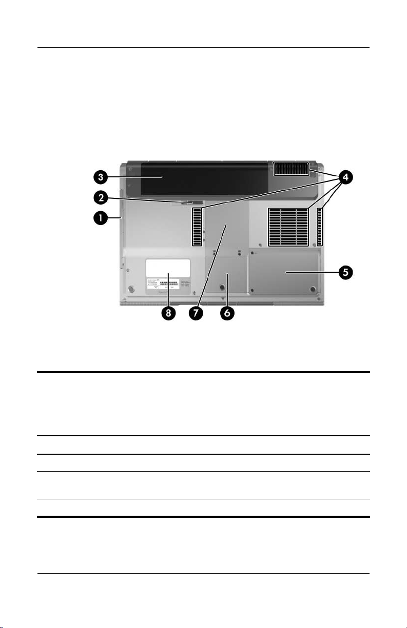
Product Description
The external components on the bottom of the
HP Pavilion dv1000 are shown below and described in
Table 1-14.
Bottom Components, HP Pavilion dv1000
Table 1-14
Bottom Components
HP Pavilion dv1000
Item Component Function
1 Optical drive Supports an optical disc.
2 Battery pack release latch Releases a battery pack from the
3 Battery pack Holds a battery pack.
1–32 Maintenance and Service Guide
battery bay.
Page 37

Table 1-14
Bottom Components
Product Description
HP Pavilion dv1000
(Continued)
Item Component Function
4 Exhaust vents (4) Provide airflow to cool internal
components.
To prevent overheating, do not
Ä
obstruct vents. Do not allow a
hard surface, such as a printer, or
a soft surface, such as pillows,
thick rugs or clothing, to block
airflow.
5 Hard drive bay Holds the internal hard drive.
6 Mini PCI compartment Holds an optional wireless LAN device.
To prevent an unresponsive
Ä
system and the display of a
warning message, install only a
Mini PCI device authorized for
use in the computer by the
governmental agency that
regulates wireless devices in your
country. If you install a device
and then receive a warning
message, remove the device to
restore computer functionality.
Then contact Customer Care.
7 Memory module
compartment
8 Label areas (2) Contain the computer serial number
Maintenance and Service Guide 1–33
Contains two memory slots that support
replaceable memory modules. The
number of preinstalled memory
modules varies by computer model.
and other applicable regulatory labels.
Page 38
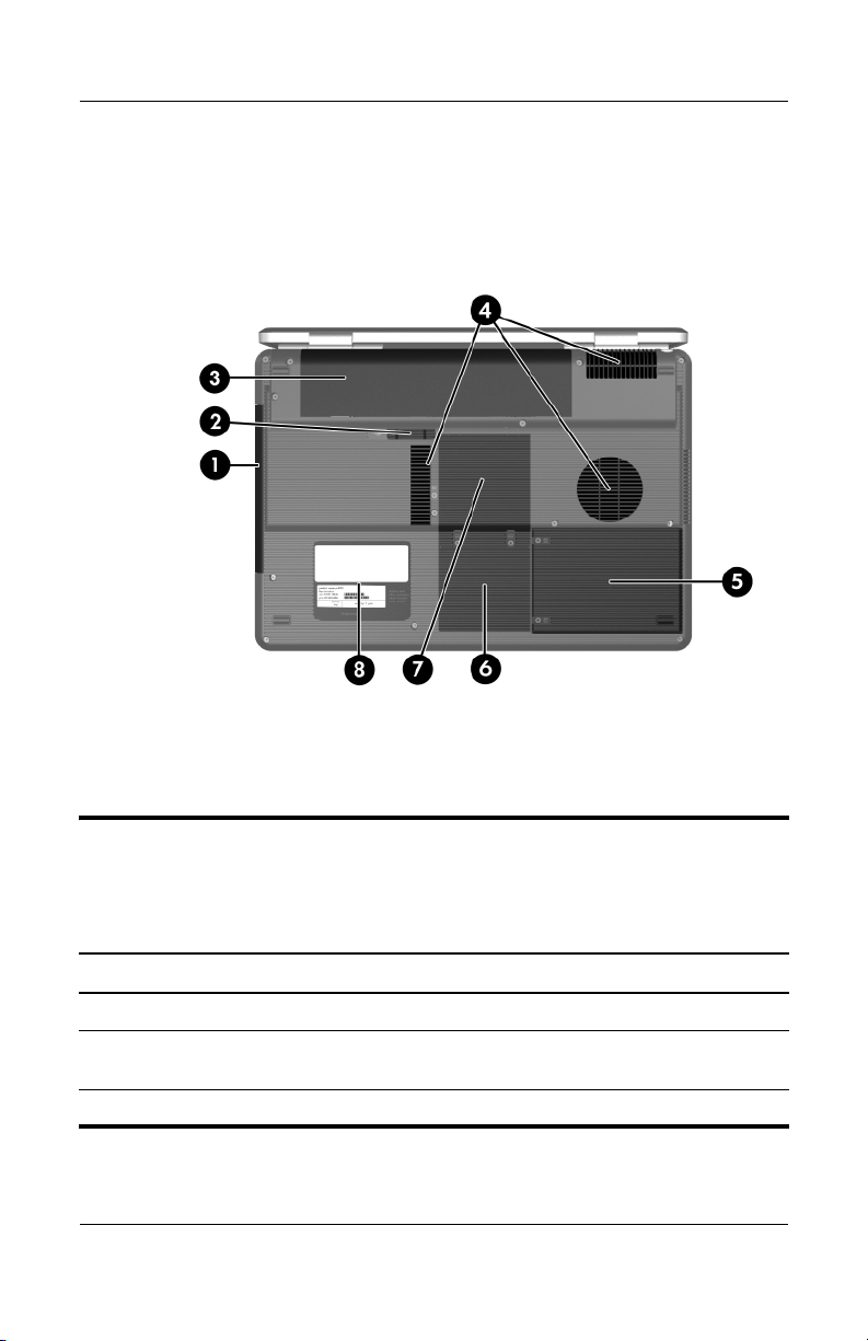
Product Description
The external components on the bottom of the
HP Compaq nx4800 and Compaq Presario V2000 are shown
below and described in Table 1-15.
Bottom Components, HP Compaq nx4800 and
Compaq Presario V2000
Table 1-15
Bottom Components
HP Compaq nx4800 and Compaq Presario V2000
Item Component Function
1 Optical drive Supports an optical disc.
2 Battery pack release latch Releases a battery pack from the
3 Battery pack Holds a battery pack.
1–34 Maintenance and Service Guide
battery bay.
Page 39

Table 1-15
Bottom Components
Product Description
HP Compaq nx4800 and Compaq Presario V2000
(Continued)
Item Component Function
4 Exhaust vents (4) Provide airflow to cool internal
components.
To prevent overheating, do not
Ä
obstruct vents. Do not allow a
hard surface, such as a printer,
or a soft surface, such as pillows,
thick rugs or clothing, to block
airflow.
5 Hard drive bay Holds the internal hard drive.
6 Mini PCI compartment Holds an optional wireless LAN device.
To prevent an unresponsive
Ä
system and the display of a
warning message, install only a
Mini PCI device authorized for
use in the computer by the
governmental agency that
regulates wireless devices in your
country. If you install a device
and then receive a warning
message, remove the device to
restore computer functionality.
Then contact Customer Care.
7 Memory module
compartment
8 Label areas (2) Contain the computer serial number
Maintenance and Service Guide 1–35
Contains 2 memory slots that support
replaceable memory modules. The
number of preinstalled memory
modules varies by computer model.
and other applicable regulatory labels.
Page 40

Product Description
1.5 Design Overview
This section presents a design overview of key parts and features
of the computer. Refer to Chapter 3, “Illustrated Parts Catalog,”
to identify replacement parts, and Chapter 5, “Removal and
Replacement Procedures,” for disassembly steps.
The system board provides the following device connections:
■ Memory module
■ Mini PCI communications devices
■ Hard drive
■ Display
■ Keyboard and TouchPad
■ Audio
■ Intel Pentium M and Celeron M processors
■ Fan
■ PC Card
CAUTION: To properly ventilate the computer, allow at least a 7.6-cm
Ä
(3-inch) clearance on the left and right sides of the computer.
The computer uses an electric fan for ventilation. The fan is
controlled by a temperature sensor and is designed to be turned
on automatically when high temperature conditions exist. These
conditions are affected by high external temperatures, system
power consumption, power management/battery conservation
configurations, battery fast charging, and software applications.
Exhaust air is displaced through the ventilation grill located on
the left side of the computer.
1–36 Maintenance and Service Guide
Page 41

Troubleshooting
WARNING: Only authorized technicians trained by HP should repair
Å
this equipment. All troubleshooting and repair procedures are detailed
to allow only subassembly-/module-level repair. Because of the
complexity of the individual boards and subassemblies, do not attempt
to make repairs at the component level or modifications to any printed
wiring board. Improper repairs can create a safety hazard. Any
indication of component replacement or printed wiring board
modification may void any warranty or exchange allowances.
2.1 Computer Setup
Computer Setup is a system information and customization utility
that can be used even when your operating system is not working
or will not load. This utility includes settings that are not
available in Windows.
2
Using Computer Setup
Information and settings in Computer Setup are accessed from
the Main, Security, Advanced, or Tools menus:
1. Turn on or restart the computer. Press
F10 = ROM-Based Setup message is displayed in
the lower-left corner of the screen.
❏ To change the language, use the cursor control keys
to navigate to the Advanced menu
❏ To view navigation information, press f1.
❏ To return to the Computer Setup menu, press esc.
Maintenance and Service Guide 2–1
f10 while the
.
Page 42

Troubleshooting
2. Select the Main, Security, Advanced, or Tools menu.
3. To close Computer Setup and restart the computer:
❏ Select Exit > Exit Saving Changes, and then press enter.
- or -
❏ Select Exit > Exit Discarding Changes, and then
enter.
press
- or -
❏ Select Exit > Load Setup Defaults, and then press enter.
4. When you are prompted to confirm your action, press f10.
Selecting from the Main Menu
Table 2 -1
Main Menu
Select To Do This
System Information ■ Change the system time and system date.
■ View identification information about the
computer.
■ View specification information about the
processor, memory and cache size, and
system ROM.
2–2 Maintenance and Service Guide
Page 43

Troubleshooting
Selecting from the Security Menu
Table 2 -2
Security Menu
Select To Do This
Administrator Password Enter, change, or delete a Administrator
password.
Power-on Password Enter, change, or delete a power-on password.
DriveLock Passwords Enable/disable DriveLock; change a DriveLock
user or master password.
DriveLock Settings are accessible only
✎
when you enter Computer Setup by turning
on (not restarting) the computer.
Password Options
(Password options can
be selected only when
a power-on password
has been set.)
Device Security Enable/disable:
*Not applicable to SuperDisk LS-120 drives.
Maintenance and Service Guide 2–3
Enable/disable:
■ QuickLock
■ QuickLock on Standby
■ QuickBlank
To enable QuickLock on Standby or
✎
QuickBlank, you must first enable
QuickLock.
■ Diskette drive startup*
■ CD-ROM or diskette startup
Settings for a DVD-ROM can be entered
✎
in the CD-ROM field.
Page 44

Troubleshooting
Selecting from the Advanced Menu
Table 2 -3
Advanced Menu
Select To Do This
Language Change the Computer Setup language.
Boot Order Enable/disable MultiBoot, which sets a startup
sequence that can include most bootable devices
and media in the system.
Accessibility Options Allows electronic and information technology to
be accessible to people with varying ranges of
abilities.
Video Memory Displays the amount of video memory available
on the computer.
Selecting from the Tools Menu
Table 2 -4
Tools M enu
Select To Do This
Hard Drive Self Test Run a quick comprehensive self test on hard
drives in the system that support the test features.
2–4 Maintenance and Service Guide
Page 45

Troubleshooting
2.2 Troubleshooting Flowcharts
Tabl e 2-5
Troubleshooting Flowcharts Overview
Flowchart Description
2.1 ”Flowchart 2.1—Initial Troubleshooting”
2.2 ”Flowchart 2.2—No Power, Part 1”
2.3 ”Flowchart 2.3—No Power, Part 2”
2.4 ”Flowchart 2.4—No Power, Part 3”
2.5 ”Flowchart 2.5—No Power, Part 4”
2.6 ”Flowchart 2.6—No Video, Part 1”
2.7 ”Flowchart 2.7—No Video, Part 2”
2.8 ”Flowchart 2.8—Nonfunctioning Docking Device (if applicable)”
2.9 ”Flowchart 2.9—No Operating System (OS) Loading”
2.10 ”Flowchart 2.10—No OS Loading, Hard Drive, Part 1”
2.11 ”Flowchart 2.11—No OS Loading, Hard Drive, Part 2”
2.12 ”Flowchart 2.12—No OS Loading, Hard Drive, Part 3”
2.13 ”Flowchart 2.13—No OS Loading, Diskette Drive”
Maintenance and Service Guide 2–5
Page 46

Troubleshooting
Tabl e 2-5
Troubleshooting Flowcharts Overview
Flowchart Description
2.14 ”Flowchart 2.14—No OS Loading, CD-ROM or DVD-ROM Drive”
2.15 ”Flowchart 2.15—No OS Loading for QuickPlay Application,
Part 1”
2.16 ”Flowchart 2.16—No OS Loading for QuickPlay Application,
Part 2”
2.17 ”Flowchart 2.17—No Audio, Part 1”
2.18 ”Flowchart 2.18—No Audio, Part 2”
2.19 ”Flowchart 2.19—Nonfunctioning Device”
2.20 ”Flowchart 2.20—Nonfunctioning Keyboard”
2.21 ”Flowchart 2.21—Nonfunctioning Pointing Device”
2.22 ”Flowchart 2.22—No Network/Modem Connection”
(Continued)
2–6 Maintenance and Service Guide
Page 47

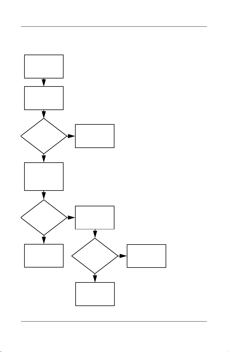
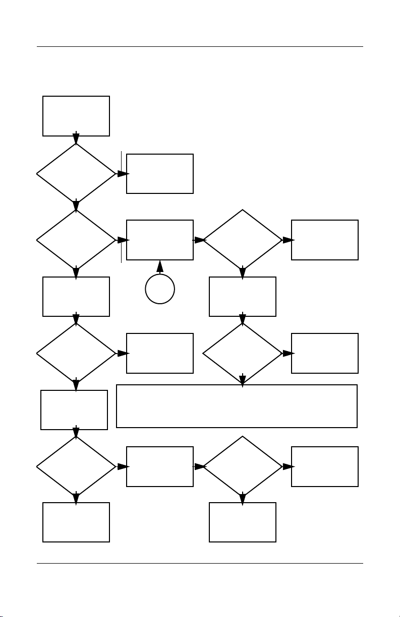
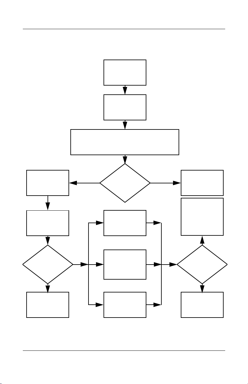
Flowchart 2.1—Initial Troubleshooting
Begin
troubleshooting.
N
Go to
Is there
power?
Y
N
Beeps,
LEDs, or error
messages?
Y
N
Is there video?
(no boot)
Y
N
Is the OS
loading?
Y
N
Is there
sound?
Y
“Flowchart
2.2—No Power,
Par t 1.”
Check
LED board,
speaker
connections.
Go to
“Flowchart
2.6—No Video,
Part 1.”
Go to
“Flowchart
2.9—No
Operating
System (OS)
Go to
“Flowchart
2.17—No Audio,
Par t 1.”
N
All drives
working?
Y
N
Keyboard/
pointing
device
working?
Y
N
Connecting
to network
or modem?
Y
End
Troubleshooting
Go to
“Flowchart
2.19—Nonfunctioning Device.”
Go to
”Flowchart
2.20—Nonfunctioning Key-
board” or
“Flowchart
2.21—Nonfunc-
tioning Pointing
Go to
“Flowchart
2.22—No
Network/Modem
Connection.”
Maintenance and Service Guide 2–7
Page 48

Troubleshooting
N
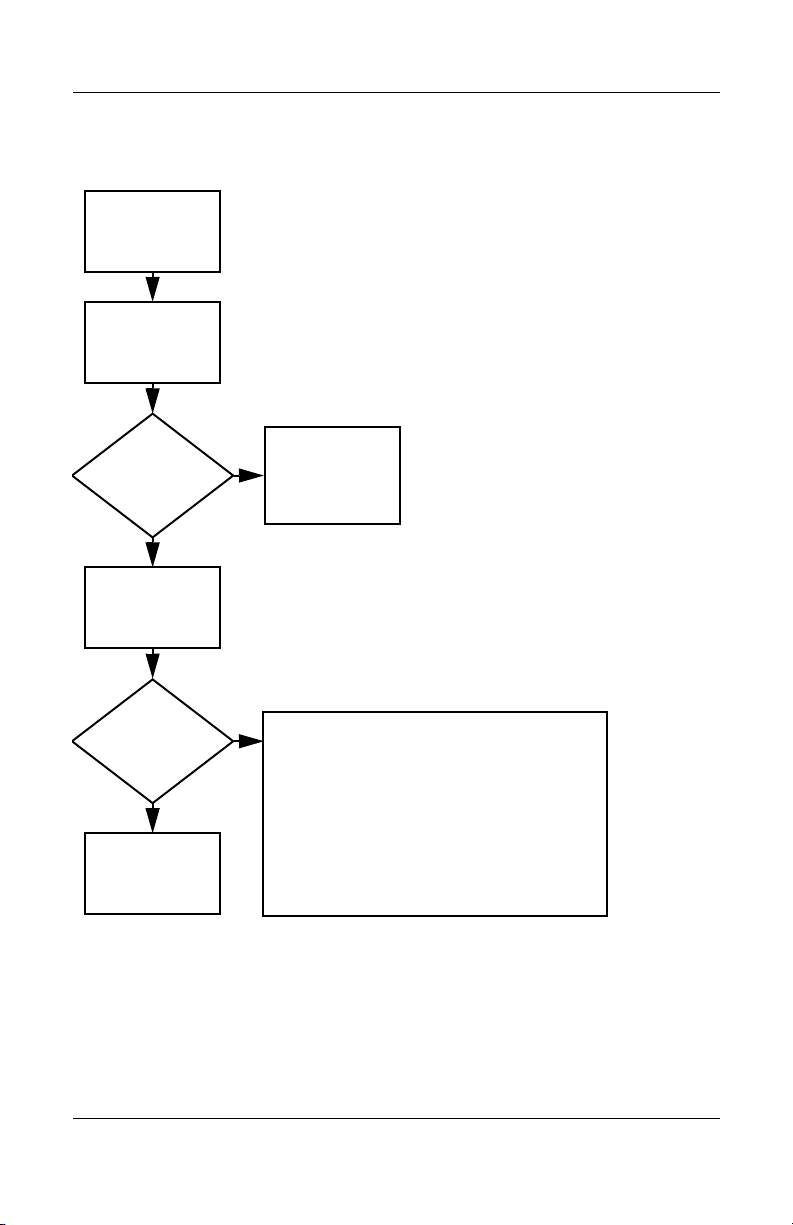
Flowchart 2.2—No Power, Part 1
No power
(power LED
is off).
Remove from
docking device
(if applicable).
N
Go to
“Flowchart
2.3—No Power,
Par t 2.”
N
Go to
“Flowchart
2.4—No Power,
Part 3.”
Y
Y
Power up
on battery
power?
Power up
on AC
power?
N
Reset
power.*
Power up
on battery
power?
Y
N
Reset
power.*
Power up
on AC
power?
Y
Y
Power up in
docking
device?
1. Reseat the power cables in the docking
device and at the AC outlet.
2. Ensure the AC power source is active.
3. Ensure that the power strip is working.
Done
YN
Done
Power up
in docking
device?
*NOTES
1. On select models, there is a separate
reset button.
2. On select models, the computer can be
reset using the Standby switch and
either the lid switch or the main power
switch.
Go to
“Flowchart
2.8—Nonfunctioning
Docking Device (if
applicable).”
2–8 Maintenance and Service Guide
Page 49
Flowchart 2.3—No Power, Part 2
N
Continued from
“Flowchart
2.2—No Power,
Par t 1.”
Visually check for
debris in battery
socket and clean
if necessary.
Y
Troubleshooting
Power on?
Check battery by
recharging it,
moving it to
another computer,
or replacing it.
Done
N
Power on?
Replace
power supply
(if applicable).
Y
N
Go to
Done
Power on?
“Flowchart
2.4—No Power,
Part 3.”
Y
Done
Maintenance and Service Guide 2–9
Page 50

Troubleshooting
Flowchart 2.4—No Power, Part 3
Continued from
“Flowchart
2.3—No Power,
Part 2.”
Plug directly
into AC outlet.
Y
Power LED
on?
N
Reseat AC adapter
in computer and
at power source.
Power on?
N
Power outlet
active?
Y
Replace
power cord.
Power on?
Done
Y
Done
External
N
Try different
outlet.
Internal or
external AC
adapter?
Internal
Go to
“Flowchart
2.5—No Power,
Part 4.”
Replace external
AC adapter.
N
Power on?
Y
Y
Done
Done
N
2–10 Maintenance and Service Guide
Page 51
Flowchart 2.5—No Power, Part 4
Continued from
“Flowchart
2.4—No Power,
Par t 3.”
Open
computer.
Troubleshooting
N
computer and
Power on?
Y
Loose or
damaged
parts?
Close
retest.
Done
Y
Reseat loose
components and
boards and
replace damaged
items.
N
Replace the following items (if applicable).
Check computer operation after each
replacement:
1. Internal DC-DC converter*
2. Internal AC adapter
3. Processor board*
4. System board*
*NOTE: Replace these items as a set to
prevent shorting out among components.
Maintenance and Service Guide 2–11
Page 52
Troubleshooting
Flowchart 2.6—No Video, Part 1
No video.
Docking Device
Stand-alone
or docking
device?
Go to
“Flowchart
2.7—No Video,
Part 2.”
*NOTE: To change from internal to
external display, use the hotkey
combination.
Stand-alone
Internal or
external
display*?
External
Adjust
brightness.
Internal
Y
Video OK? Done
N
Check for bent
pins on cable.
N
Video OK?
Adjust
brightness.
Video OK? Done
N
A
Press lid
switch to ensure
operation.
Video OK? Done
N
Replace the following one at a time. Test after each replacement.
1. Cable between computer and computer display (if applicable)
2. Display
3. System board
Tr y
another
display.
Internal and
external
video OK?
Y
Y
N
Replace
system
board.
YY
Done
Done
2–12 Maintenance and Service Guide
Page 53
Flowchart 2.7—No Video, Part 2
Continued from
“Flowchart
2.6—No Video,
Part 1.”
Remove
computer from
docking device,
if connected.
Troubleshooting
Adjust
display
brightness.
N
Video OK?
Y
Check that computer is properly
seated in docking device, for
bent pins on cable, and for
monitor connection.
Y
Video OK?
N
Adjust external
monitor display.
Go to “A” in
“Flowchart
2.6—No Video,
Part 1.”
Done
Check brightness
of external
monitor.
Video OK?
N
Try another
external
monitor.
Internal
and external
video OK?
N
Go to
“Flowchart
2.8—Nonfunctioning
Docking Device (if
applicable).”
Y
Done
Y
Done
Maintenance and Service Guide 2–13
Page 54
Troubleshooting
Flowchart 2.8—Nonfunctioning Docking Device
(if applicable)
Nonfunctioning
docking device.
Reseat power
cord in docking
device and
power outlet.
Check voltage
setting on docking
device.
Reset monitor
cable connector at
docking device.
Docking
device
operating?
Y
Done
Remove computer,
replace docking
N
device.
Reinstall computer
into docking
station.
Docking
device
operating?
N
Test replacement
docking device
with new
computer.
Y
Done
2–14 Maintenance and Service Guide
Page 55

Troubleshooting
Flowchart 2.9—No Operating System (OS)
Loading
No OS
loading.*
Reseat power
cord in docking
device and
power outlet.
No OS loading from hard drive,
“Flowchart 2.10—No OS Loading,
go to
go to
Hard Drive, Part 1.”
No OS loading from diskette drive,
“Flowchart 2.13—No OS Loading,
Diskette Drive.”
No OS loading from CD- or DVD-ROM drive,
“Flowchart 2.14—No OS Loading,
go to
CD-ROM or DVD-ROM Drive.”
No OS loading from network,
“Flowchart 2.22—No Network/Modem
go to
*NOTE: Before beginning troubleshooting,
always check cable connections, cable ends,
and drives for bent or damaged pins.
Connection.”
Maintenance and Service Guide 2–15
Page 56

Troubleshooting
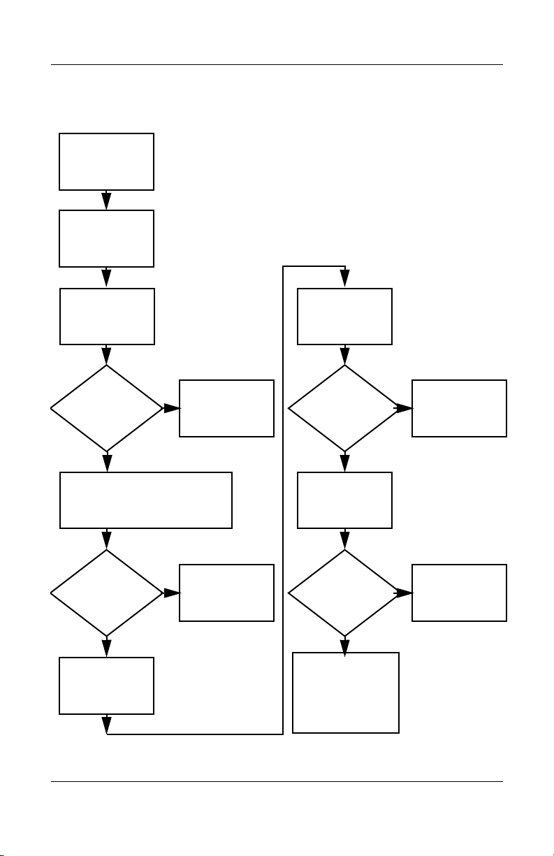
Flowchart 2.10—No OS Loading, Hard Drive,
Part 1
OS not
loading from
hard drive.
Nonsystem
disk
message?
N
Reseat
external
hard drive.
OS loading?
N
Boot
from
CD?
Y
Check the Setup
utility for correct
booting order.
Boot
from
hard drive?
Y
Done
Y
Go to
“Flowchart
2.11—No OS
Loading,
Hard Drive, Part 2.”
Y
Done
N
N
Boot
from
diskette?
Y
N
Change boot
priority through
the Setup utility
and reboot.
Go to
“Flowchart
2.13—No OS
Loading,
Diskette Drive.”
N
Boot
from
hard drive?
Go to
“Flowchart
2.19—Nonfunctioning
Device.”
Y
2–16 Maintenance and Service Guide
Page 57
Troubleshooting
Flowchart 2.11—No OS Loading, Hard Drive,
Part 2
Continued from
“Flowchart
2.10—No OS
Loading,
Hard Drive, Part 1.”
CD or
diskette in
drive?
Y
Remove
diskette and
reboot.
N
1. Replace
hard drive.
2. Replace
system board.
N
Reseat
hard drive.
Hard drive
accessible?
Run FDISK.
Y
Done
Boot
from
hard drive?
N
Boot
from diskette
drive?
Y
Hard drive
accessible?
Y
Go to
“Flowchart
2.12—No OS
Loading,
Hard Drive, Part 3.”
Y
N
Diskette Drive.”
N
Done
Go to
“Flowchart
2.13—No OS
Loading,
Done
Hard drive
partitioned?
Y
Hard drive
formatted?
Y
Y
Computer
booted?
Go to
“Flowchart
2.12—No OS
Loading,
Hard Drive, Part 3.”
N
Create partition,
and then format
hard drive to
bootable
C:\ prompt.
N
Format hard drive
and bring to
abootable
C:\ prompt.
Load OS using
System Restore
N
(if applicable).
CD
Maintenance and Service Guide 2–17
Page 58

Troubleshooting
Flowchart 2.12—No OS Loading, Hard Drive,
Part 3
Continued from
“Flowchart
2.11—No OS
Loading,
Hard Drive, Part 2.”
N
System
files on hard
drive?
Y
Install OS
and reboot.
Virus
on
hard drive?
N
Run SCANDISK
and check for
bad sectors.
Can bad
sectors
be fixed?
Y
Fix bad
sectors.
Y
Clean virus.
loading from
hard drive?
Y
OS
Done
N
Y
Diagnostics
on diskette?
Replace
hard drive.
N
N
Replace
hard drive.
Run diagnostics
and follow
recommendations.
N
Boot from
hard drive?
Replace
hard drive.
Y
Done
2–18 Maintenance and Service Guide
Page 59

Troubleshooting
N
N
Flowchart 2.13—No OS Loading, Diskette Drive
Y
OS not loading
from
diskette drive.
Reseat
diskette drive.
OS
loading?
Done
N
Nonsystem
disk message?
Y
Bootable
diskette
in drive?
N
Install bootable
diskette and
reboot computer.
Y
N
Boot
from another
device?
Y
Go to
“Flowchart
2.19—Nonfunction
ing Device.”
N
Diskette
drive enabled
in the Setup
utility?
Enable drive
and cold boot
computer.
Y
Y
Is diskette
drive boot
order
correct?
Reset the
computer. Refer to
Section 1.2,
“Resetting the
Computer,”
instructions.
for
Check diskette
for system files.
Try different
diskette.
Nonsystem
disk error?
N
loading?
N
OS
Y
1. Replace
diskette drive.
2. Replace system
board.
Y
Done
Change boot
priority using
the Setup utility.
Go to
“Flowchart
2.19—Nonfunctioning
Device.”
Maintenance and Service Guide 2–19
Page 60

Troubleshooting
Flowchart 2.14—No OS Loading, CD-ROM
or DVD-ROM Drive
No OS
loading from
CD-ROM or
DVD-ROM Drive.
Boots from
CD or DVD?
N
Reseat
drive.
N
bootable disc.
Disc
in drive?
Install
Y
Bootable
disc in
drive?
Y
Try another
bootable disc.
N
Install bootable
disc and
reboot
computer.
Y
Done
Y
Boots from
CD or DVD?
Done
N
N
Booting
from another
device?
Y
Go to
“Flowchart
2.19—Nonfunctioning
Device.”
Y
Booting
order
correct?
N
Correct boot
order using
the Setup utility.
2–20 Maintenance and Service Guide
Reset the
computer. Refer to
Section 1.2,
“Resetting the
Computer,”
instructions.
for
Go to
“Flowchart
2.19—Nonfunctioning
Device.”
Page 61

Troubleshooting
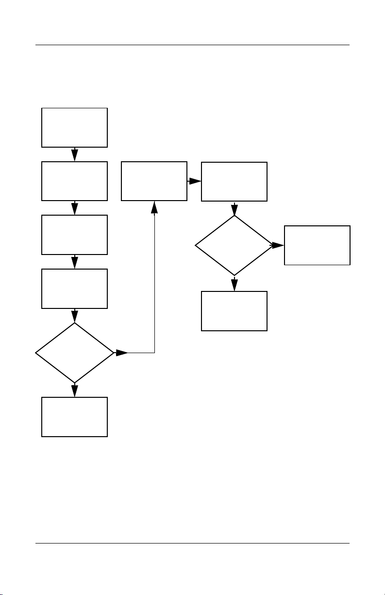
Flowchart 2.15—No OS Loading for QuickPlay
Application, Part 1
No OS loads for
QuickPlay
application.
Reseat
hard drive.
Y
OS loads for
QuickPlay
application?
Done
N
Reboot the computer
from the
CD.
HP QuickPlay
Follow the on-screen
instructions.
Y
OS loads for
QuickPlay
application?
Done
N
1. Reboot the computer to Windows OS.
2. Go to Control Panel > Administrative Tools > Computer Management > Disk
Management and delete the Linux QuickPlay partition. The Linux QuickPlay partition will
appear in the lower left corner as “Healthy (Unknown Partition).”
3. Reboot the computer from the
HP QuickPlay CD.
Follow the on-screen instructions.
Y
OS loads for
QuickPlay
application?
Done
N
Go to
“Flowchart 2.16—No
OS Loading for
QuickPlay
Application, Part 2.”
Maintenance and Service Guide 2–21
Page 62

Troubleshooting
Flowchart 2.16—No OS Loading for QuickPlay
Application, Part 2
Continued from
“Flowchart
2.15—No OS
Loading for
QuickPlay
Application, Part 1.”
1. Reformat the hard drive.
2. Insert the Windows installation CD and follow the on-screen instructions.
3. When you are prompted “To create the new partition, enter a size below and press Enter,”
enter
204 MB as the reserved partition size. This process creates two partitions. The first
partition is used for Windows. The second partition is used for QuickPlay.
4. Continue with the on-screen instructions to complete the installation of Windows on the
first partition.
Reboot the computer
from the
on-screen instructions.
HP QuickPlay
Follow the
CD.
Y
OS loads for
QuickPlay
application?
Done
N
1. Replace the hard drive.
2. Insert the Windows Installation CD and follow the on-screen instructions.
3. When you are prompted “To create the new partition, enter a size below and press Enter,”
enter
204 MB as the reserved partition size. This process creates 2 partitions. The first
partition is used for Windows. The second partition is used for QuickPlay.
4. Continue with the on-screen instructions to complete the installation of Windows on the
first partition.
N
Reboot the computer
from the
on-screen instructions.
HP QuickPlay
Follow the
CD.
2–22 Maintenance and Service Guide
OS loads for
QuickPlay
application?
Done
Y
Page 63

Flowchart 2.17—No Audio, Part 1
N
Tur n up audio
No audio.
internally or
externally.
Audio? Done
N
Troubleshooting
Y
Computer in
docking device
(if applicable)?
Y
Undock
Internal
audio?
N
Go to
“Flowchart
2.18—No Audio,
Par t 2.”
Y
Go to
“Flowchart
2.18—No Audio,
Par t 2.”
Replace the following docking device
components one at a time, as applicable.
Check audio status after each change.
1. Reseat docking device audio cable.
2. Replace audio cable.
3. Replace speaker.
4. Replace docking device audio board.
5. Replace backplane board.
6. Replace I/O board.
Y
Go to
“Flowchart
2.19—Nonfunctioning
Device.”
Audio? Done
N
Maintenance and Service Guide 2–23
Page 64

Troubleshooting
Flowchart 2.18—No Audio, Part 2
Continued from
“Flowchart
2.17—No Audio,
Part 1.”
N
Audio
driver in OS
configured?
Y
N
Correct
drivers for
application?
Y
Connect to
external
speaker.
Reload
audio drivers.
Load drivers and
set configuration
in OS.
Replace audio
board and
Audio?
YN
speaker
connections
in computer
(if applicable).
Audio? Done
1. Replace internal speakers.
2. Replace audio board (if applicable).
3. Replace system board.
YN
2–24 Maintenance and Service Guide
Page 65
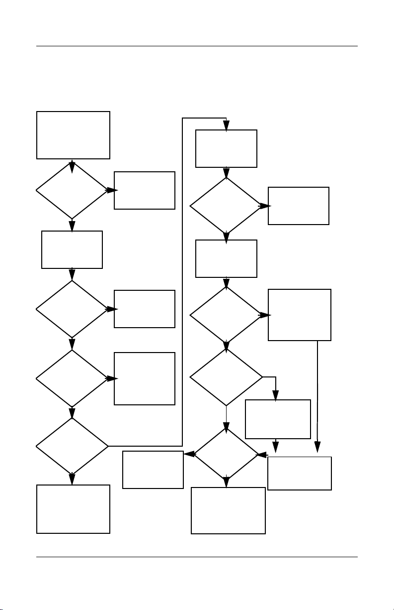
Flowchart 2.19—Nonfunctioning Device
Nonfunctioning
device.
Reseat
device.
Unplug the nonfunctioning device from
the computer and inspect cables and plugs for
bent or broken pins or other damage.
Y
Clear
CMOS.
Reattach device.
Close computer,
plug in power,
and reboot.
Any physical
device detected?
N
Replace hard drive.
Operating System
Troubleshooting
Fix or
replace
broken item.
Go to
“Flowchart
2.9—No
(OS) Loading.”
N
Device
boots
properly?
Replace NIC.
If integrated NIC,
replace system
board.
Y
Done
Maintenance and Service Guide 2–25
Replace diskette
drive.
Device
boots
properly?
Y
Done
N
Page 66

Troubleshooting
Flowchart 2.20—Nonfunctioning Keyboard
Keyboard
not operating
properly.
Connect computer
to good external
keyboard.
N
External
works?
Y
Reseat internal
keyboard
connector
(if applicable).
Y
device
Replace
system
board.
N
OK?
Replace internal
keyboard or
cable.
Y
Done Done
OK?
N
Replace
system
board.
2–26 Maintenance and Service Guide
Page 67

Troubleshooting
Flowchart 2.21—Nonfunctioning Pointing
Device
Pointing device
not operating
properly.
Connect computer
to good external
pointing device.
N
External
device
works?
Y
Reseat internal
pointing device
connector
(if applicable).
Replace
system
board.
N
OK?
Replace internal
pointing device
or cable.
Y
Y
Done Done
OK?
N
Replace
system
board.
Maintenance and Service Guide 2–27
Page 68

Troubleshooting
Flowchart 2.22—No Network/Modem
Connection
No network
or modem
connection.
N
Network
or modem
jack active?
Y
Digital
line?
N
Replace jack
or have jack
activated.
Y
Connect
to nondigital
line.
Y
Done
NIC/modem
configured
Y
Disconnect all
power from
the computer
and open.
in OS?
N
Reload
drivers and
reconfigure.
OK?
N
Replace
NIC/modem
(if applicable).
Y
Reseat
NIC/modem
(if applicable).
OK? Done
N
Replace
system
board.
2–28 Maintenance and Service Guide
Page 69
Illustrated Parts Catalog
This chapter provides an illustrated parts breakdown and a
reference for spare part numbers and option part numbers.
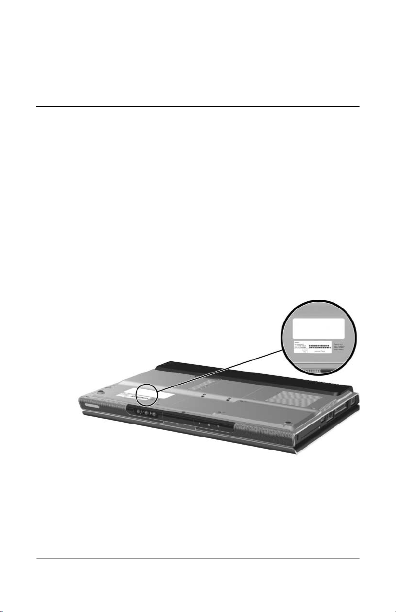
3.1 Serial Number Location
When ordering parts or requesting information, provide the
computer serial number and model number located on the bottom
of the computer.
3
Serial Number Location
Maintenance and Service Guide 3–1
Page 70

Illustrated Parts Catalog
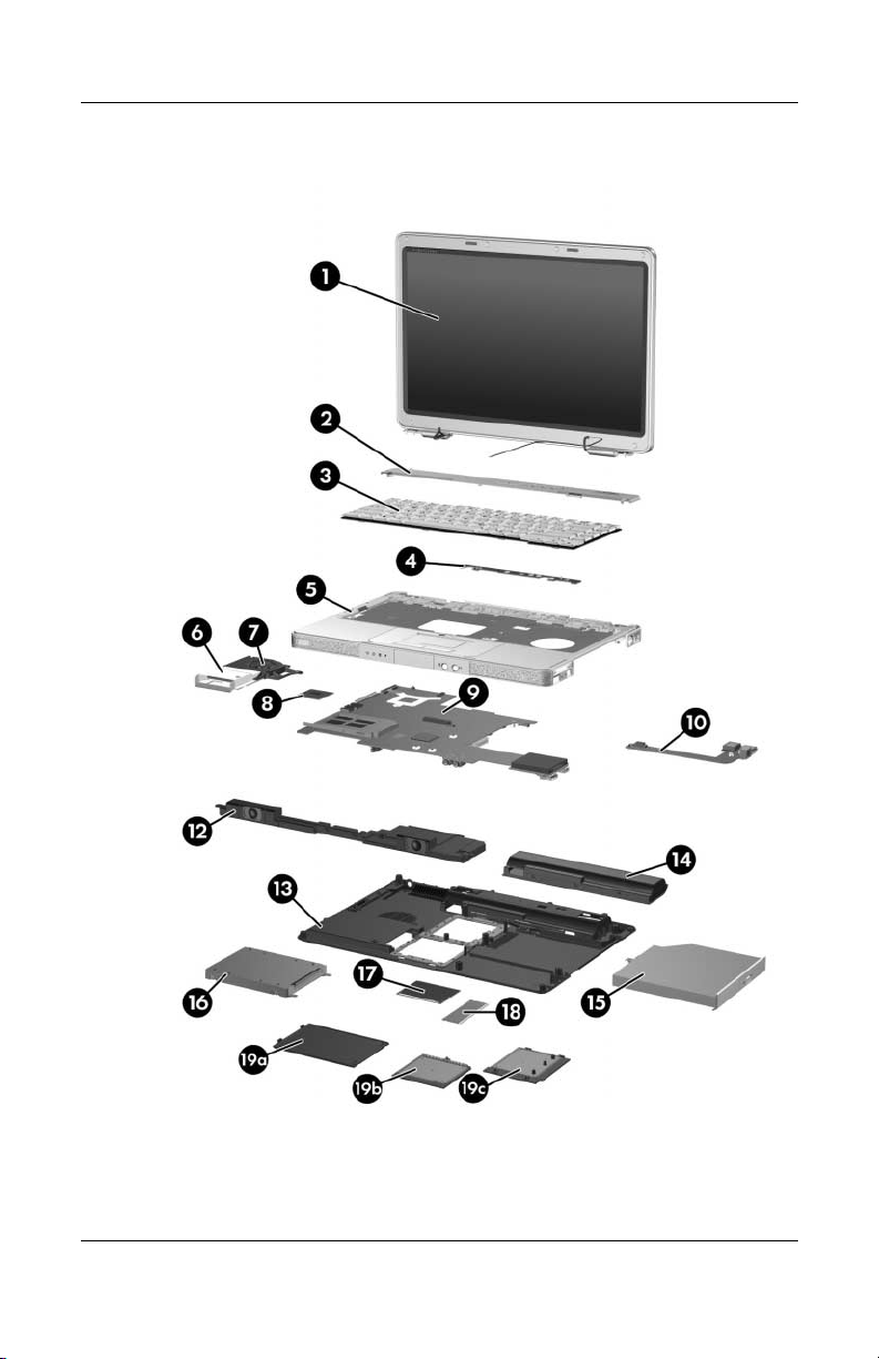
3.2 Computer Major Components
Computer Major Components, HP Pavilion dv1000
3–2 Maintenance and Service Guide
Page 71

Illustrated Parts Catalog
Tabl e 3-1
Spare Parts: Computer Major Components
Spare Part
Item Description
1 Display assemblies (include wireless antenna boards and cables)
For use on HP Pavilion dv1000 models
14.0-inch, WXGA, SVA with Brightview
14.0-inch, WXGA
For use on HP Compaq nx4800 models
14.0-inch, WXGA, SVA with Brightview
14.0-inch, WXGA
For use on Compaq Presario V2000 models
14.0-inch, WXGA, SVA with Brightview
14.0-inch, WXGA
Display hinge brackets (not illustrated) 382077-001
Display hinge covers (for use only with Compaq
V2000 models; not illustrated)
Number
373054-001
367783-001
373060-001
373528-001
373055-001
367784-001
382078-001
Maintenance and Service Guide 3–3
Page 72

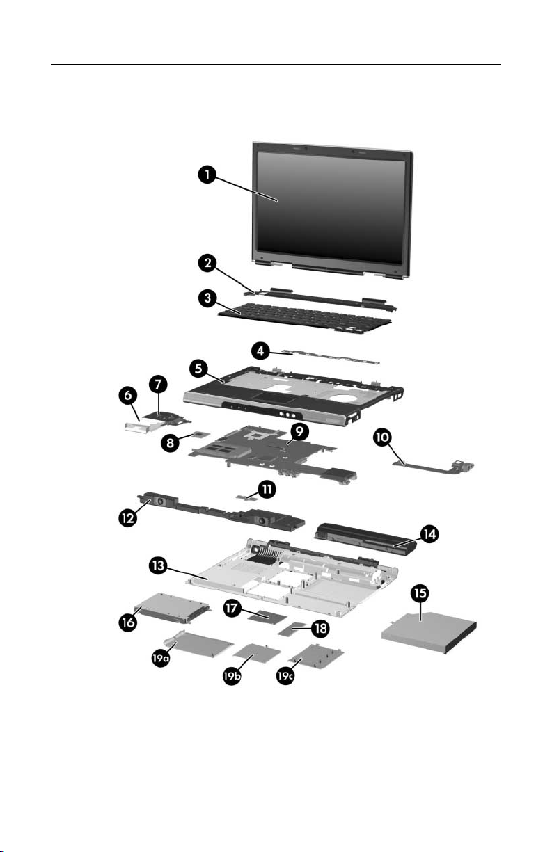
Illustrated Parts Catalog
Computer Major Components, HP Compaq nx4800 and
Compaq Presario V2000
3–4 Maintenance and Service Guide
Page 73

Table 3 -1
Illustrated Parts Catalog
Spare Parts: Computer Major Components
Item Description
2 Switch covers (include wireless button and light)
For use on HP Pavilion dv1000 models with wireless
capability
For use on HP Pavilion dv1000 models without
wireless capability
For use on HP Compaq nx4800 and Compaq Presario
V2000 models with a 1394 port, S-Video-out jack,
expansion port, Memory Reader, and wireless
capability
For use on HP Compaq nx4800 and Compaq Presario
V2000 models with a 1394 port, S-Video-out jack,
expansion port, and Memory Reader without wireless
capability
For use on Compaq Presario V2000 models without a
1394 port, S-Video-out jack, expansion port, and
Memory Reader
(Continued)
Spare Part
Number
367781-001
367780-001
367782-001
367779-001
373532-001
Maintenance and Service Guide 3–5
Page 74

Illustrated Parts Catalog
Computer Major Components, HP Pavilion dv1000
3–6 Maintenance and Service Guide
Page 75

Table 3 -1
Illustrated Parts Catalog
Spare Parts: Computer Major Components
Item Description
3 Keyboards
For use on HP Pavilion dv1000 models in:
Asia Pacific,
Australia,
Canada,
Hong Kong,
the People’s
Republic
of China, and
the United
States
Belgium
Denmark
France
French Canada
Germany
Greece
Israel
For use on HP Compaq nx4800 models in Japan 367777-291
367778-001
367778-A
41
367778-081
367778-051
367778-121
367778-041
367778-DJ1
367778-BB1
Italy
Korea
Latin America
Europe and
the Netherlands
Norway
Portugal
Saudi Arabia
Spain
Sweden/Finland
Switzerland
Ta i wa n
Thailand
The United
Kingdom
(Continued)
Spare Part
Number
367778-061
367778-AD1
367778-161
367778-331
367778-091
367778-131
367778-171
367778-071
367778-B71
367778-111
367778-AB1
367778-281
367778-031
Maintenance and Service Guide 3–7
Page 76

Illustrated Parts Catalog
Computer Major Components, HP Compaq nx4800 and
Compaq Presario V2000
3–8 Maintenance and Service Guide
Page 77

Table 3 -1
Illustrated Parts Catalog
Spare Parts: Computer Major Components
Item Description
3 Keyboards
For use on Compaq Presario V2000 models in:
Asia Pacific,
Australia,
Hong Kong,
the People’s
Republic of
China, and the
United States
Denmark
Europe and
the Netherlands
France
French Canada
4 LED boards (include cable, not illustrated)
For use on HP Pavilion dv1000 models 367797-001
For use on HP Compaq nx4800 and
Compaq Presario V2000 models
5 Top covers (include TouchPad)
(Continued)
367777-001
367777-081
367777-331
367777-051
367777-121
Italy
Korea
Latin America
Norway
Sweden/Finland
Spain
Ta i wa n
Thailand
The United
Kingdom
(Continued)
Spare Part
Number
367777-061
367777-AD1
367777-161
367777-091
367777-B71
367777-071
367777-AB1
367777-281
367777-031
367798-001
For use on HP Pavilion dv1000 models 367761-001
For use on HP Compaq nx4800 models 373529-001
For use on Compaq Presario V2000 models with a
1394 port, S-Video-out jack, expansion port, and
Memory Reader
For use on Compaq Presario V2000 models without a
1394 port, S-Video-out jack, expansion port, and
Memory Reader
Maintenance and Service Guide 3–9
367762-001
373531-001
Page 78

Illustrated Parts Catalog
Computer Major Components, HP Pavilion dv1000
3–10 Maintenance and Service Guide
Page 79

Tabl e 3-1
Illustrated Parts Catalog
Spare Parts: Computer Major Components
(Continued)
Spare Part
Item Description
6 Heat sink (includes thermal pad) 367796-001
7 Fan (includes thermal pad) 367795-001
8 Processors (include thermal pad)
Intel Pentium M 745 (1.8-GHz) with 400-MHz FSB
Intel Pentium M 735 (1.7-GHz) with 400-MHz FSB
Intel Pentium M 725A (1.6-GHz) with 400-MHz FSB
Intel Pentium M 725 (1.6-GHz) with 400-MHz FSB
Intel Pentium M 715A (1.5-GHz) with 400-MHz FSB
Intel Pentium M 715 (1.5-GHz) with 400-MHz FSB
Intel Pentium M 705 (1.5-GHz) with 400-MHz FSB
Intel Pentium M 710 (1.4-GHz) with 400-MHz FSB
Intel Celeron M 340 (1.5-GHz) with 400-MHz FSB
Intel Celeron M 370 (1.5-GHz) with 400-MHz FSB
Intel Celeron M 360 (1.4-GHz) with 400-MHz FSB
Intel Celeron M 330 (1.4-GHz) with 400-MHz FSB
Intel Celeron M 350 (1.3-GHz) with 400-MHz FSB
Number
373053-001
373052-001
394825-001
367771-001
380690-001
383431-001
375979-001
376588-001
367768-001
383876-001
380033-001
367767-001
380032-001
Maintenance and Service Guide 3–11
Page 80

Illustrated Parts Catalog
Computer Major Components, HP Compaq nx4800 and
Compaq Presario V2000
3–12 Maintenance and Service Guide
Page 81

Tabl e 3-1
Illustrated Parts Catalog
Spare Parts: Computer Major Components
Item Description
9 System boards (include disk cell RTC battery)
855, for use on full-featured HP Pavilion dv1000
models in countries other than Japan
855, for use on full-featured HP Pavilion dv1000
models in Japan
852GM, for use on full-featured HP Pavilion dv1000
models in Japan
For use on HP Pavilion dv1000 models with Intel
Pentium M processors
For use on HP Pavilion dv1000 models with Intel
Celeron M processors
For use on HP Compaq nx4800 and Compaq Presario
V2000 models with Intel Pentium M processors
For use on Compaq Presario V2000 models with Intel
Celeron M processors
PC Card assemblies
Silver with 1-dot PC Card eject lever 385869-001
(Continued)
Spare Part
Number
381062-001
391884-001
381063-001
367799-001
367800-001
373522-001
373523-001
Black with 3-dot PC Card eject lever 389524-001
Black with 1-dot PC Card eject lever 389525-001
10 USB/S-Video controller boards
For use on HP Pavilion dv1000 models and
HP Compaq nx4800 and Compaq Presario V2000
models with a 1394 port, S-Video-out jack, expansion
port, and digital memory card reader
For use only on Compaq Presario V2000 models
without a 1394 port, S-Video-out jack, expansion port,
and Memory Reader
Maintenance and Service Guide 3–13
367794-001
373533-001
Page 82

Illustrated Parts Catalog
Computer Major Components, HP Pavilion dv1000
3–14 Maintenance and Service Guide
Page 83

Tabl e 3-1
Illustrated Parts Catalog
Spare Parts: Computer Major Components
Item Description
11 Menu control button board (includes bracket and
cable, for use only on HP Pavilion dv1000
computer models)
12 Speaker assemblies
For use on HP Pavilion dv1000 models 367793-001
For use on HP Compaq nx4800 and Compaq Presario
V2000 models
13 Base enclosures
For use on HP Pavilion dv1000 models 367763-001
For use on HP Compaq nx4800 and Compaq Presario
V2000 models
14 Battery packs
12-cell, 8.8-AHr 367760-001
6-cell, 4.4-AHr 367759-001
6-cell, 4.0-AHr 398065-001
15 Optical drives (include bezel)
(Continued)
Spare Part
Number
373535-001
374625-001
367764-001
For use on HP Pavilion dv1000 models
8X DVD-ROM Drive
24X DVD/CD-RW Combo Drive
4X DVD+RW/R and CD-RW Combo Drive
4X DVD±RW/R and CD-RW Combo Drive
8X DVD±RW/R and CD-RW Combo Drive
8X DVD±RW/R and CD-RW Combo Drive,
LightScribe
8X DVD±RW/R and CD-RW Dual Layer Combo Drive
Maintenance and Service Guide 3–15
367789-001
367790-001
373625-001
375981-001
375983-001
383877-001
383896-001
Page 84
Illustrated Parts Catalog
Computer Major Components, HP Compaq nx4800 and
Compaq Presario V2000
3–16 Maintenance and Service Guide
Page 85

Tabl e 3-1
Illustrated Parts Catalog
Spare Parts: Computer Major Components
Item Description
15 Optical drives
For use on HP Compaq nx4800 and Compaq Presario
V2000 models
8X DVD-ROM Drive
24X DVD/CD-RW Combo Drive
4X DVD+RW/R and CD-RW Combo Drive
4X DVD±RW/R and CD-RW Combo Drive
8X DVD±RW/R and CD-RW Combo Drive
8X DVD±RW/R and CD-RW Combo Drive,
LightScribe
8X DVD±RW/R and CD-RW Dual Layer Combo Drive
16 Hard drives (include frame and connector)
5400-rpm
80-GB
60-GB
4200-rpm
100-GB
80-GB
60-GB
40-GB
(Continued)
(Continued)
Spare Part
Number
373524-001
373525-001
373626-001
375982-001
375984-001
383878-001
389897-001
377651-001
375980-001
381721-001
367788-001
367787-001
367786-001
Maintenance and Service Guide 3–17
Page 86
Illustrated Parts Catalog
Computer Major Components, HP Pavilion dv1000
3–18 Maintenance and Service Guide
Page 87

Tabl e 3-1
Illustrated Parts Catalog
Spare Parts: Computer Major Components
Item Description
17 Mini PCI communications cards
802.11b/g Broadcomm (for use in most of the world)
802.11b/g Broadcomm (for use in the rest of the
world)
802.11b/g Broadcomm (Japan, for use only on
HP Compaq nx4800 models)
802.11b Intel (for use in most of the world)
802.11b Intel (for use in the rest of the world)
802.11b/g Intel (for use in most of the world)
802.11b/g Intel (for use in the rest of the world)
Bluetooth® Wireless LAN
18 Memory modules (266 MHz)
1024-MB
512-MB
256-MB
Miscellaneous Plastics Kit
For use on HP Pavilion dv1000 models 367765-001
(Continued)
Spare Part
Number
373047-001
373048-001
373061-291
373023-001
373024-001
373026-001
373025-001
376651-001
and
376652-001
367775-001
367774-001
367773-001
For use on HP Compaq nx4800 and
Compaq Presario V2000 models
Includes:
19a
19b
19c
Maintenance and Service Guide 3–19
Hard drive cover (includes two captive screws)
Memory module compartment cover (includes 2 captive screws)
Mini PCI compartment cover (includes 2 captive screws)
Computer feet (not illustrated)
367766-001
Page 88
Illustrated Parts Catalog
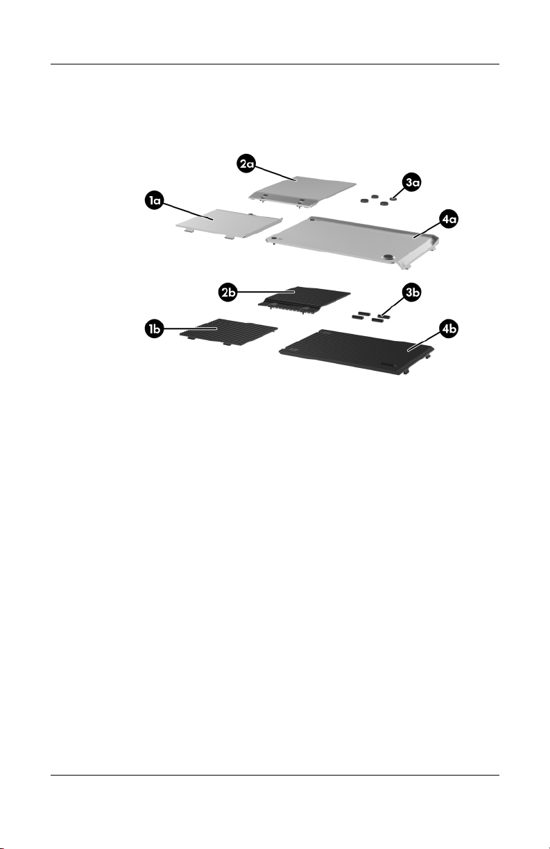
3.3 Miscellaneous Plastics Kit
Miscellaneous Plastics Kit
3–20 Maintenance and Service Guide
Page 89

Spare Part Number Information
Item Description
Miscellaneous Plastics Kit
For use on HP Pavilion dv1000 models 367765-001
Includes:
1a
2a
3a
4a
Mini PCI compartment cover
Memory module compartment cover
Computer feet
Hard drive cover
Illustrated Parts Catalog
Table 3-2
Miscellaneous Plastics Kit
Spare Part
Number
For use on HP Compaq nx4800 and
Compaq Presario V2000 models
Includes:
1b
2b
3b
4b
Maintenance and Service Guide 3–21
Mini PCI compartment cover
Memory module compartment cover
Computer feet
Hard drive cover
367766-001
Page 90

Illustrated Parts Catalog
3.4 Mass Storage Devices
Mass Storage Devices
Table 3-3
Mass Storage Devices
Spare Part Number Information
Spare Part
Item Description
1 Hard drives (include frame and connector)
5400-rpm
80-GB
60-GB
3–22 Maintenance and Service Guide
Number
377651-001
375980-001
Page 91

Table 3-3
Mass Storage Devices
Illustrated Parts Catalog
Spare Part Number Information
Item Description
Hard drives
4200-rpm
100-GB
80-GB
60-GB
40-GB
2 Optical drives
For use on HP Pavilion dv1000 models
8X DVD-ROM Drive
24X DVD/CD-RW Combo Drive
4X DVD+RW/R and CD-RW Combo Drive
4X DVD±RW/R and CD-RW Combo Drive
8X DVD±RW/R and CD-RW Combo Drive
8X DVD±RW/R and CD-RW Combo Drive,
LightScribe
8X DVD±RW/R and CD-RW Dual Layer Combo Drive
For use on HP Compaq nx4800 and Compaq Presario
V2000 models
8X DVD-ROM Drive
24X DVD/CD-RW Combo Drive
4X DVD+RW/R and CD-RW Combo Drive
4X DVD±RW/R and CD-RW Combo Drive
8X DVD±RW/R and CD-RW Combo Drive
8X DVD±RW/R and CD-RW Combo Drive,
LightScribe
8X DVD±RW/R and CD-RW Dual Layer Combo Drive
(Continued)
Spare Part
Number
(Continued)
381721-001
367788-001
367787-001
367786-001
367789-001
367790-001
373625-001
375981-001
375983-001
383877-001
383896-001
373524-001
373525-001
373626-001
375982-001
375984-001
383878-001
389897-001
Maintenance and Service Guide 3–23
Page 92

Illustrated Parts Catalog
Table 3-3
Mass Storage Devices
Spare Part Number Information
Item Description
USB diskette drive (not illustrated) 359118-001
USB digital drive (not illustrated) 364727-001
HP USB pocket drive (not illustrated) 338796-001
(Continued)
Spare Part
Number
3–24 Maintenance and Service Guide
Page 93

Illustrated Parts Catalog
3.5 Miscellaneous
Tabl e 3-4
Spare Parts: Miscellaneous (not illustrated)
Spare Part
Description
Logo Kits
For use on HP Pavilion dv1000 models 373058-001
For use on HP Compaq nx4800 models 373530-001
For use on Compaq Presario V2000 models 373059-001
Wired headset with volume control 371693-001
Personal Video Recorder 352950-001
Number
HP remote control (for use only on HP dv1000 computer
models)
USB travel mouse 309674-001
65-watt AC adapter 371790-001
Screw Kit (includes the following screws; refer to Appendix C, “Screw Listing,”
for more information on screw specifications and usage)
For use on HP Pavilion dv1000 models 367776-001
For use on HP Compaq nx4800 and
Compaq Presario V2000 models
■ Phillips PM2.5×4.0 screw
■ Phillips PM2.0×7.0 round head screw
■ Phillips PM2.0×7.0 screw
■ Phillips PM2.0×5.0 screw
Maintenance and Service Guide 3–25
■ Phillips PM2.0×4.0 screw
■ Phillips PM2.0×3.0 screw
■ Phillips PM1.5×2.0 screw
371694-001
373534-001
Page 94

Illustrated Parts Catalog
Tabl e 3-4
Spare Parts: Miscellaneous (not illustrated)
Description
Power cords
For use in:
Australia and New Zealand 373979-011
Belgium, Europe, Finland, France, Germany, Greece,
the Netherlands, Norway, Portugal, Spain, and Sweden
Canada, French Canada, Latin America, Taiwan, Thailand,
and the United States
Denmark 373979-081
Hong Kong and the United Kingdom 373979-031
Israel 373979-BB1
Italy 373979-061
Japan 373979-291
Korea 373979-AD1
The People’s Republic of China 373979-AA1
Switzerland 373979-111
Taiwan 373979-AB1
(Continued)
Spare Part
Number
373979-021
373979-001
3–26 Maintenance and Service Guide
Page 95

Illustrated Parts Catalog
3.6 Sequential Part Number Listing
Table 3-5
Spare Parts: Sequential Part Number Listing
Spare Part
Number Description
309674-001 USB travel mouse
352950-001 Personal Video Recorder
359118-001 USB diskette drive
364727-001 USB digital drive
367759-001 Battery pack, 6-cell, 4.4-AHr
367760-001 Battery pack, 12-cell, 8.8-AHr
367761-001 Top cover for use on HP Pavilion dv1000 models (includes
TouchPad)
367762-001 Top cover for use on Compaq Presario V2000 models with a
1394 port, S-Video-out jack, expansion port, and Memory
Reader (includes TouchPad)
367763-001 Base enclosure for use on HP Pavilion dv1000 models
367764-001 Base enclosure for use on HP Compaq nx4800 and
Compaq Presario V2000 models
367765-001 Miscellaneous Plastics Kit for use on HP Pavilion dv1000
models
367766-001 Miscellaneous Plastics Kit for use on HP Compaq nx4800 and
Compaq Presario V2000 models
367767-001 Processor, Intel Celeron M 330 (1.4-GHz) with 400-MHz FSB
(includes thermal pad)
367768-001 Processor, Intel Celeron M 340 (1.5-GHz) with 400-MHz FSB
(includes thermal pad)
367771-001 Processor, Intel Pentium M 725 (1.6-GHz) with 400-MHz FSB
(includes thermal pad)
Maintenance and Service Guide 3–27
Page 96

Illustrated Parts Catalog
Table 3-5
Spare Parts: Sequential Part Number Listing
Spare Part
Number Description
367773-001 Memory module, 256-MB (266 MHz)
367774-001 Memory module, 512-MB (266 MHz)
367775-001 Memory module, 1024-MB (266 MHz)
367776-001 Screw Kit for use on HP Pavilion dv1000 models
367777-001 Keyboard for use on Compaq Presario V2000 models in Asia
Pacific, Australia, Hong Kong,
People’s Republic of China, and the United States
367777-031 Keyboard for use on Compaq Presario V2000 models in the
United Kingdom
367777-051 Keyboard for use on Compaq Presario V2000 models in
France
367777-061 Keyboard for use on Compaq Presario V2000 models in Italy
367777-071 Keyboard for use on Compaq Presario V2000 models in
Spain
367777-081 Keyboard for use on Compaq Presario V2000 models in
Denmark
367777-091 Keyboard for use on Compaq Presario V2000 models in
Norway
(Continued)
367777-121 Keyboard for use on Compaq Presario V2000 models in
French Canada
367777-161 Keyboard for use on Compaq Presario V2000 models in Latin
America
367777-281 Keyboard for use on Compaq Presario V2000 models in
Thailand
367777-291 Keyboard for use on HP Compaq nx4800 computer models in
Japan
3–28 Maintenance and Service Guide
Page 97

Table 3-5
Illustrated Parts Catalog
Spare Parts: Sequential Part Number Listing
Spare Part
Number Description
367777-331 Keyboard for use on Compaq Presario V2000 models in the
Netherlands
367777-AB1 Keyboard for use on Compaq Presario V2000 models in
Ta i wa n
367777-AD1 Keyboard for use on Compaq Presario V2000 models in
Korea
367777-B71 Keyboard for use on Compaq Presario V2000 models in
Sweden/Finland
367778-001 Keyboard for use on HP Pavilion dv1000 models in Asia
Pacific, Australia, Canada, Hong Kong, People’s Republic of
China, and the United States
367778-031 Keyboard for use on HP Pavilion dv1000 models in the United
Kingdom
367778-041 Keyboard for use on HP Pavilion dv1000 models in Germany
367778-051 Keyboard for use on HP Pavilion dv1000 models in France
367778-061 Keyboard for use on HP Pavilion dv1000 models in Italy
367778-071 Keyboard for use on HP Pavilion dv1000 models in Spain
367778-081 Keyboard for use on HP Pavilion dv1000 models in Denmark
(Continued)
367778-091 Keyboard for use on HP Pavilion dv1000 models in Norway
367778-111 Keyboard for use on HP Pavilion dv1000 models in
Switzerland
367778-121 Keyboard for use on HP Pavilion dv1000 models in French
Canada
367778-131 Keyboard for use on HP Pavilion dv1000 models in Portugal
367778-161 Keyboard for use on HP Pavilion dv1000 models in Latin
America
Maintenance and Service Guide 3–29
Page 98

Illustrated Parts Catalog
Table 3-5
Spare Parts: Sequential Part Number Listing
Spare Part
Number Description
367778-171 Keyboard for use on HP Pavilion dv1000 models in Saudi
Arabia
367778-281 Keyboard for use on HP Pavilion dv1000 models in Thailand
367778-331 Keyboard for use on HP Pavilion dv1000 models in Europe
and the Netherlands
367778-A41 Keyboard for use on HP Pavilion dv1000 models in Belgium
367778-AB1 Keyboard for use on HP Pavilion dv1000 models in Taiwan
367778-AD1 Keyboard for use on HP Pavilion dv1000 models in Korea
367778-B71 Keyboard for use on HP Pavilion dv1000 models Finland and
Sweden
367778-BB1 Keyboard for use on HP Pavilion dv1000 models in Israel
367778-DJ1 Keyboard for use on HP Pavilion dv1000 models in Greece
367779-001 Switch cover for use on HP Compaq nx4800 and
Compaq Presario V2000 models with a 1394 port,
S-Video-out jack, expansion port, and Memory Reader without
wireless capability
367780-001 Switch cover for use on HP Pavilion dv1000 models without
wireless capability
(Continued)
367781-001 Switch cover for use on HP Pavilion dv1000 models with
wireless capability
367782-001 Switch cover for use on HP Compaq nx4800 and
Compaq Presario V2000 models with a 1394 port,
S-Video-out jack, expansion port, and Memory Reader with
wireless capability
367783-001 Display assembly, 14.0-inch, WXGA for use on
for use on HP Pavilion dv1000 models
3–30 Maintenance and Service Guide
Page 99

Table 3-5
Illustrated Parts Catalog
Spare Parts: Sequential Part Number Listing
Spare Part
Number Description
367784-001 Display assembly, 14.0-inch, WXGA for use on
Compaq Presario V2000 models
367786-001 Hard drive, 60-GB, 4200-rpm (includes frame and connector)
367787-001 Hard drive, 40-GB, 4200-rpm (includes frame and connector)
367788-001 Hard drive, 80-GB, 4200-rpm (includes frame and connector)
367789-001 8X DVD-ROM Drive for use on
HP Pavilion dv1000 models
367790-001 24X DVD/CD-RW Combo Drive for use on
HP Pavilion dv1000 models
367793-001 Speaker assembly for use on HP Pavilion dv1000 models
367794-001 USB/S-Video controller board for use on HP Pavilion dv1000
models and HP Compaq nx4800 and
Compaq Presario V2000 models with a 1394 port,
S-Video-out jack, expansion port, and digital memory card
reader
367795-001 Fan (includes thermal pad)
367796-001 Heat sink (includes thermal pad)
367797-001 LED board for use on HP Pavilion dv1000 models (includes
cable)
(Continued)
367798-001 LED board for use on HP Compaq nx4800 and
Compaq Presario V2000 models (includes cable)
367799-001 System board for use on HP Pavilion dv1000 models with Intel
Pentium M processors
367800-001 System board for use on HP Pavilion dv1000 models with Intel
Celeron M processors
371693-001 Wired headset with volume control
Maintenance and Service Guide 3–31
Page 100

Illustrated Parts Catalog
Table 3-5
Spare Parts: Sequential Part Number Listing
Spare Part
Number Description
371694-001 HP remote control (for use only on HP dv1000
computer models)
371790-001 65-watt AC adapter
373023-001 Mini PCI communications card, 802.11b Intel (for use in most
of the world)
373024-001 Mini PCI communications card, 802.11b Intel (for use in the
rest of the world)
373025-001 Mini PCI communications card, 802.11b/g Intel (for use in the
rest of the world)
373026-001 Mini PCI communications card, 802.11b/g Intel (for use in
most of the world)
373047-001 Mini PCI communications card, 802.11b/g Broadcomm (for
use in most of the world)
373048-001 Mini PCI communications card, 802.11b/g Broadcomm (for
use in the rest of the world)
373052-001 Processor, Intel Pentium M 735 (1.7-GHz) with
400-MHz FSB (includes thermal pad)
373053-001 Processor, Intel Pentium M 745 (1.8-GHz) with
400-MHz FSB (includes thermal pad)
373054-001 Display assembly, 14.0-inch, WXGA, SVA with Brightview for
use on HP Pavilion dv1000 models
(Continued)
373055-001 Display assembly, 14.0-inch, WXGA, SVA with Brightview for
use on Compaq Presario V2000 models
373058-001 Logo Kit for use on HP Pavilion dv1000 models
373059-001 Logo Kit for use on Compaq Presario V2000 models
373060-001 Display assembly, 14.0-inch, WXGA, SVA with Brightview for
use on HP Compaq nx4800 models
3–32 Maintenance and Service Guide
 Loading...