

Page 1

HP DreamColor Z27x Display
User Guide
Page 2

© 2014 Hewlett-Packard Development
Company, L.P.
ENERGY STAR and the ENERGY STAR
mark are registered U.S. marks. Microsoft,
Windows, and Windows 7 are U.S.
registered trademarks of the Microsoft
group of companies.
The information contained herein is subject
to change without notice. The only
warranties for HP products and services are
set forth in the express warranty statements
accompanying such products and services.
Nothing herein should be construed as
constituting an additional warranty. HP shall
not be liable for technical or editorial errors
or omissions contained herein.
First Edition: April 2014
Document Part Number: 748432-001
Page 3

About This Guide
This guide provides information on monitor features, setting up the monitor, and technical
specifications.
WARNING! Text set off in this manner indicates that failure to follow directions could result in bodily
harm or loss of life.
CAUTION: Text set off in this manner indicates that failure to follow directions could result in
damage to equipment or loss of information.
NOTE: Text set off in this manner provides important supplemental information.
iii
Page 4

iv About This Guide
Page 5

Table of contents
1 Product Features ............................................................................................................................................ 1
HP Z27x Monitor .................................................................................................................................. 1
2 Safety and Maintenance Guidelines .............................................................................................................. 3
Important Safety Information ................................................................................................................ 3
Maintenance Guidelines ....................................................................................................................... 3
Cleaning the Monitor ............................................................................................................ 4
Shipping the Monitor ............................................................................................................ 4
3 Setting Up the Monitor ................................................................................................................................... 5
Use Caution When Setting Up the Monitor .......................................................................................... 5
Installing the Stand ............................................................................................................................... 6
Rear Components ................................................................................................................................ 7
Connecting the Cables ......................................................................................................................... 8
Front Panel Controls .......................................................................................................................... 13
Adjusting the Monitor .......................................................................................................................... 14
Turning on the Monitor ....................................................................................................................... 17
HP Watermark and Image Retention Policy ....................................................................................... 18
Connecting USB Devices ................................................................................................................... 18
Removing the Monitor Stand .............................................................................................................. 18
Mounting the Monitor .......................................................................................................................... 19
Mounting the Monitor Using the Quick Release 2 Mounting Bracket ................................ 20
Mounting the Monitor Without Using the Quick Release 2 Mounting Bracket ................... 23
Installing an Optional HP Hood Kit ..................................................................................................... 23
Locating the Serial Number and Product Number .............................................................................. 25
Locating the Information Card ............................................................................................................ 25
Attaching a Device to the Rear of the Monitor .................................................................................... 26
Installing a Cable Lock ....................................................................................................................... 27
4 Operating the Monitor .................................................................................................................................. 28
Software and Utilities .......................................................................................................................... 28
The Information File ........................................................................................................... 28
The Image Color Matching File .......................................................................................... 28
Installing the .INF and .ICM Files ....................................................................................................... 29
Installing from the Disc ...................................................................................................... 29
Downloading from the Internet ........................................................................................... 29
v
Page 6

Updating the Firmware ....................................................................................................................... 29
Selecting a Color Space Preset ......................................................................................................... 31
Adjusting Luminance .......................................................................................................................... 31
Understanding the Z27x Image Adjustment Options .......................................................................... 32
Use Video Levels (16–235) ............................................................................................... 32
Overscan the Frame .......................................................................................................... 32
Show Only the Blue Channel ............................................................................................. 33
Using the Z27x Aspect Ratio Management Options .......................................................................... 33
The “Fill To” Options .......................................................................................................... 33
Fill to Source Aspect Ratio (Proportional) ......................................................... 33
Fill to Entire Screen (Non-Proportional) ............................................................ 33
Fill to Screen Width (Proportional) .................................................................... 34
Fill to Screen Height (Proportional) ................................................................... 34
Pixel-for-Pixel .................................................................................................... 34
“Fill To” Examples ............................................................................................. 34
Working with 2K and 4K Digital Cinema Image Formats ................................................................... 36
Using the Digital Cinema Display Options ......................................................................... 37
Show Entire DCI Container ............................................................................... 37
Crop to DCI 1.85:1 Aspect Ratio ....................................................................... 37
Crop to DCI 2.39:1 Aspect Ratio ....................................................................... 37
Show Cropped Region ...................................................................................... 38
Set Cropped Region Opacity ............................................................................ 38
Displaying 4K Source Video .............................................................................. 38
Obey Aspect Ratio Display Option .................................................................... 38
Scale and Show Center Extraction ................................................................... 38
Scale and Show Left Side of Frame .................................................................. 38
Scale and Show Right Side of Frame ............................................................... 38
Show 4K Source Video Pixel-for-Pixel .............................................................. 38
Next 4K Corner ................................................................................. 39
Scroll 4K Region ............................................................................... 39
Using Picture-in-Picture (PIP) and Picture-beside-Picture (PBP) ...................................................... 39
Using PIP as a Confidence Monitor ................................................................................... 40
Use Video Levels (16–235) ............................................................................... 40
Overscan Within PIP ......................................................................................... 40
Digital Cinema Options ..................................................................................... 40
Changing the Bezel Button Functions ................................................................................................ 40
Changing the Bezel Function Button Mode ........................................................................................ 41
Adjusting the Bezel Button LEDs ....................................................................................................... 43
Using Auto-Sleep Mode ..................................................................................................................... 43
Using the On-Screen Display Menu ................................................................................................... 44
Color Space Menu ............................................................................................................. 45
vi
Page 7

Video Input Menu ............................................................................................................... 46
Image Adjustment Menu .................................................................................................... 46
PIP Control Menu .............................................................................................................. 48
Language Menu ................................................................................................................. 49
Management Menu ............................................................................................................ 50
Menu and Message Control Menu ..................................................................................... 53
Information and Factory Reset Menus ............................................................................... 55
Introduction to Color Calibration ......................................................................................................... 55
Preparing to Calibrate ........................................................................................................ 56
Calibrating the Z27x Using the Onscreen Menus .............................................................. 57
Recalibrate the Current Preset .......................................................................... 57
Select and Modify a Preset ............................................................................... 57
Auto EDID Update .............................................................................................................................. 58
Appendix A Technical Specifications ............................................................................................................ 60
Z27x Model ......................................................................................................................................... 60
Recognizing Preset Display Resolutions ............................................................................................ 61
Z27x Model ........................................................................................................................ 61
Appendix B Support and Troubleshooting ................................................................................................... 63
Solving Common Problems ................................................................................................................ 63
Button Lockouts .................................................................................................................................. 64
Product Support ................................................................................................................................. 65
Preparing to Call Technical Support ................................................................................................... 65
Appendix C Agency Regulatory Notices ....................................................................................................... 66
Federal Communications Commission Notice ................................................................................... 66
Modifications ...................................................................................................................... 66
Cables ................................................................................................................................ 66
Declaration of Conformity for Products Marked with the FCC Logo (United States Only) ................. 66
Canadian Notice ................................................................................................................................. 67
Avis Canadien .................................................................................................................................... 67
European Union Regulatory Notice .................................................................................................... 67
German Ergonomics Notice ............................................................................................................... 67
Japanese Notice ................................................................................................................................. 68
Korean Notice ..................................................................................................................................... 68
Power Cord Set Requirements ........................................................................................................... 68
Japanese Power Cord Requirements ................................................................................ 68
Product Environmental Notices .......................................................................................................... 68
ENERGY STAR® Qualification .......................................................................................... 68
vii
Page 8

Materials Disposal ............................................................................................................. 69
Disposal of Waste Equipment by Users in Private Household in the European Union ..... 69
HP Recycling Program ...................................................................................................... 70
Chemical Substances ........................................................................................................ 70
Restriction of Hazardous Substances (RoHS) ................................................................... 70
Turkey EEE Regulation ..................................................................................................... 71
Ukraine Restriction of Hazardous Substances .................................................................. 71
Appendix D LCD Monitor Quality and Pixel Policy ....................................................................................... 72
viii
Page 9

1 Product Features
HP Z27x Monitor
The LCD (liquid crystal display) monitor has an active matrix, thin-film transistor (TFT) panel. The
monitor features include:
● 68.58 cm (27-inch) diagonal viewable area display with 2560 x 1440 resolution, plus full-screen
support for lower resolutions; includes custom scaling to support 4096×2160 or 3840×2160
resolutions using a variety of presentation methods
Wide color gamut to provide 100% coverage of both AdobeRGB and sRGB color spaces and
●
98% of DCI-P3
Ability to accurately remap the color gamut of the monitor (within the supported color gamut of
●
the panel) to enable the selection of the color space and very accurately set the RGB primaries
for consistent and repeatable colors
Very high color and luminance stability (with typical use)
●
Calibrated color space factory presets for sRGB, AdobeRGB, DCI-P3, BT.709, BT.601, and
●
BT-2020 so the monitor is ready to use for color critical applications with minimal setup
Re-calibrateable color presets that allow you to re-calibrate to a standard or custom color space
●
by specifying the color primaries, white point, gamma, and luminance (requires the separately
purchased HP DreamColor Calibration Solution kit)
Option to return to Factory Calibration settings or User Calibration settings to easily restore the
●
monitor to the factory or user settings
User calibration that requires the DreamColor calibration solution kit (sold separately) or a third-
●
party measurement device
Built-in support for the Klein K10-A Photo Research PR-6xx, 7xx series, and Konica Minolta
●
CA-310 measurement devices
Updatable monitor firmware to enable HP to quickly and easily provide solutions to identified
●
problems and provide custom solutions
Four reconfigurable front bezel Function buttons to quickly select the most commonly used
●
operations
Wide viewing angle to allow viewing from a sitting or standing position, or moving from side-to-
●
side
● Adjustable tilt, height, swivel, and pivot capabilities
Removable stand for flexible monitor panel mounting solutions
●
HP Quick Release 2 to quickly install the monitor on the stand with a simple click and remove it
●
with the convenient sliding tab release
Optional thin client mounting bracket that attaches to the rear of the stand (purchased
●
separately)
40mm x 40mm VESA standard mounting holes on rear panel for mounting an external device
●
Easy access pull-out information card with the information needed when contacting HP support
●
HP Z27x Monitor 1
Page 10

Two video signal inputs to support DisplayPort digital with one cable provided
●
● Video signal input to support HDMI digital with cable provided
Analog audio output for headphones or an optional HP speaker bar
●
SPDIF digital audio output
●
● RJ-45 network connector
● DreamColor USB 2.0 ports for connecting a color calibration tool or updating firmware
USB 3.0 hub with one upstream port (cable provided) that connects to the computer and four
●
downstream ports that connect to USB devices
● Plug and play capability if supported by your operating system
Security slot provision on rear of monitor for optional cable lock
●
Cable management feature for placement of cables and cords
●
● On-Screen Display (OSD) adjustments in several languages for easy setup and screen
optimization
HDCP (High-Bandwidth Digital Content Protection) copy protection on all digital inputs
●
Software and documentation disc that includes monitor drivers, product documentation, and
●
Windows-based calibration software
2 Chapter 1 Product Features
Page 11

2 Safety and Maintenance Guidelines
Important Safety Information
A power cord is included with the monitor. If another cord is used, use only a power source and
connection appropriate for this monitor. For information on the correct power cord set to use with the
monitor, refer to the
WARNING! To reduce the risk of electric shock or damage to the equipment:
• Plug the power cord into an AC outlet that is easily accessible at all times.
• Disconnect power from the computer by unplugging the power cord from the AC outlet.
• If provided with a 3-pin attachment plug on the power cord, plug the cord into a grounded (earthed)
3-pin outlet. Do not disable the power cord grounding pin, for example, by attaching a 2-pin adapter.
The grounding pin is an important safety feature.
For your safety, do not place anything on power cords or cables. Arrange them so that no one may
accidentally step on or trip over them. Do not pull on a cord or cable. When unplugging from the
electrical outlet, grasp the cord by the plug.
To reduce the risk of serious injury, read the Safety and Comfort Guide. It describes proper
workstation, setup, posture, and health and work habits for computer users, and provides important
electrical and mechanical safety information. This guide is located on the Web at
ergo.
Power Cord Set Requirements on page 68.
http://www.hp.com/
CAUTION: For the protection of the monitor, as well as the computer, connect all power cords for
the computer and its peripheral devices (such as a monitor, printer, scanner) to some form of surge
protection device such as a power strip or Uninterruptible Power Supply (UPS). Not all power strips
provide surge protection; the power strips must be specifically labeled as having this ability. Use a
power strip whose manufacturer offers a Damage Replacement Policy so you can replace the
equipment, if surge protection fails.
Use the appropriate and correctly sized furniture designed to properly support your HP LCD monitor.
WARNING! LCD monitors that are inappropriately situated on dressers, bookcases, shelves, desks,
speakers, chests, or carts may fall over and cause personal injury.
Care should be taken to route all cords and cables connected to the LCD monitor so that they can not
be pulled, grabbed, or tripped over.
Maintenance Guidelines
To enhance the performance and extend the life of the monitor:
Do not open the monitor cabinet or attempt to service this product yourself. Adjust only those
●
controls that are covered in the operating instructions. If the monitor is not operating properly or
has been dropped or damaged, contact an authorized HP dealer, reseller, or service provider.
● Use only a power source and connection appropriate for this monitor, as indicated on the label/
back plate of the monitor.
Be sure the total ampere rating of the products connected to the outlet does not exceed the
●
current rating of the electrical outlet, and the total ampere rating of the products connected to the
Important Safety Information 3
Page 12

cord does not exceed the rating of the cord. Look on the power label to determine the ampere
rating (AMPS or A) for each device.
Install the monitor near an outlet that you can easily reach. Disconnect the monitor by grasping
●
the plug firmly and pulling it from the outlet. Never disconnect the monitor by pulling the cord.
● Turn the monitor off when not in use. You can substantially increase the life expectancy of the
monitor by using a screen saver program and turning off the monitor when not in use.
NOTE: Monitors with a “burned-in image” are not covered under the HP warranty.
Slots and openings in the cabinet are provided for ventilation. These openings must not be
●
blocked or covered. Never push objects of any kind into cabinet slots or other openings.
Do not drop the monitor or place it on an unstable surface.
●
Do not allow anything to rest on the power cord. Do not walk on the cord.
●
● Keep the monitor in a well-ventilated area, away from excessive light, heat or moisture.
When removing the monitor stand, you must lay the monitor face down on a soft area to prevent
●
it from getting scratched, defaced, or broken.
Cleaning the Monitor
1. Turn off the monitor and unplug the power cord from the back of the unit.
2. Dust the monitor by wiping the screen and the cabinet with a soft, clean antistatic cloth.
3. For more difficult cleaning situations, use a 50/50 mix of water and Isopropyl alcohol.
CAUTION: Spray the cleaner onto a cloth and use the damp cloth to gently wipe the screen
surface. Never spray the cleaner directly on the screen surface. It may run behind the bezel and
damage the electronics.
CAUTION: Do not use cleaners that contain any petroleum based materials such as benzene,
thinner, or any volatile substance to clean the monitor screen or cabinet. These chemicals may
damage the monitor.
Shipping the Monitor
Keep the original packing box in a storage area. You may need it later if you move or ship the
monitor.
4 Chapter 2 Safety and Maintenance Guidelines
Page 13
3 Setting Up the Monitor
To set up the monitor, ensure that the power is turned off to the monitor, computer system, and other
attached devices, then follow the instructions below.
NOTE: Be sure the master power switch, located on the rear panel of the monitor, is in the off
position. The master power switch turns off all power to the monitor.
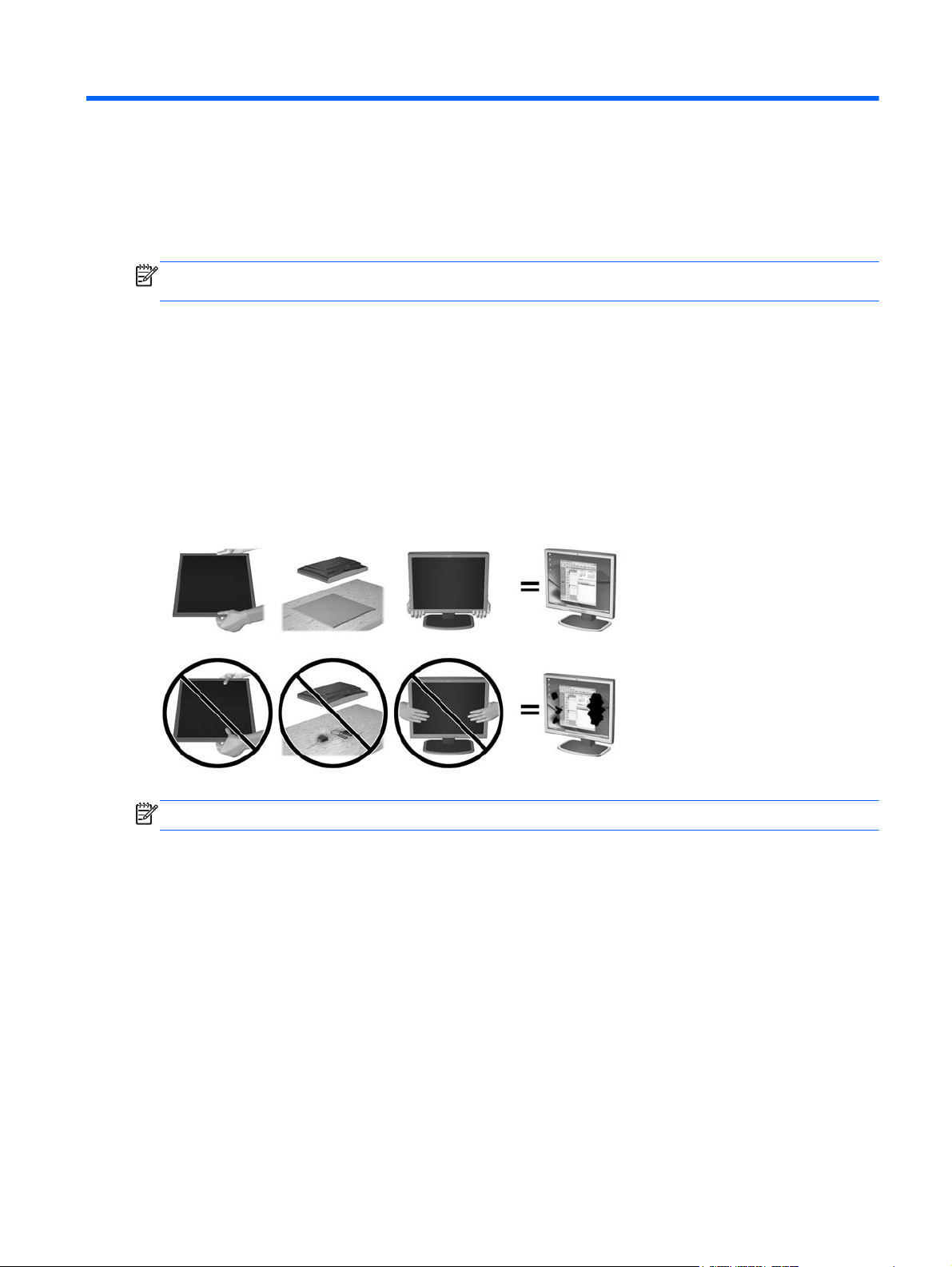
Use Caution When Setting Up the Monitor
To prevent damage to the monitor, do not touch the surface of the LCD panel. Pressure on the panel
may cause non-uniformity of color or disorientation of the liquid crystals. If this occurs the screen will
not recover to its normal condition.
If installing a base, lay the monitor face down on a flat surface covered with a protective sheet foam
or non-abrasive cloth. This prevents the screen from getting scratched, defaced or broken as well as
damage to the front panel buttons.
NOTE: Your monitor may look different from the monitor in this illustration.
Use Caution When Setting Up the Monitor 5
Page 14
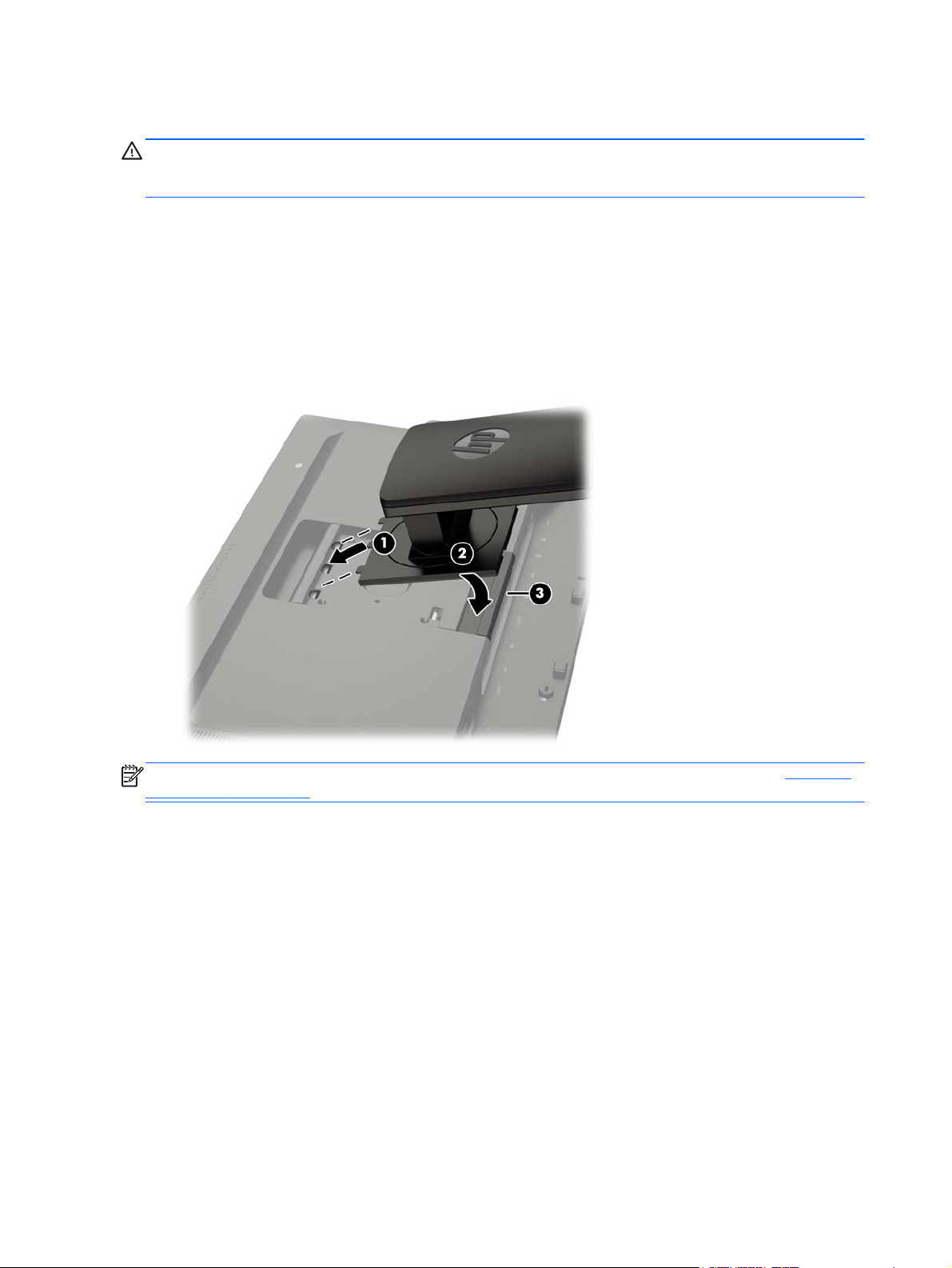
Installing the Stand
CAUTION: Do not touch the surface of the LCD panel. Pressure on the panel may cause non-
uniformity of color or disorientation of the liquid crystals. If this occurs the screen will not recover to its
normal condition.
The monitor uses the HP Quick Release 2 for easy mounting and unmounting of the monitor panel.
To mount the panel onto the stand:
1. Lay the monitor panel face down on a flat surface covered by a clean, dry cloth.
2. Slide the top of the mounting plate (1) on the stand under the upper lip of the recess in the back
of the panel.
3. Lower the bottom of the stand's mounting plate (2) into the recess until it snaps into place.
4. The HP Quick Release 2 latch (3) pops up when the stand is locked in place.
NOTE: If you are mounting the monitor to a mounting fixture instead of the stand refer to Mounting
the Monitor on page 19
6 Chapter 3 Setting Up the Monitor
Page 15
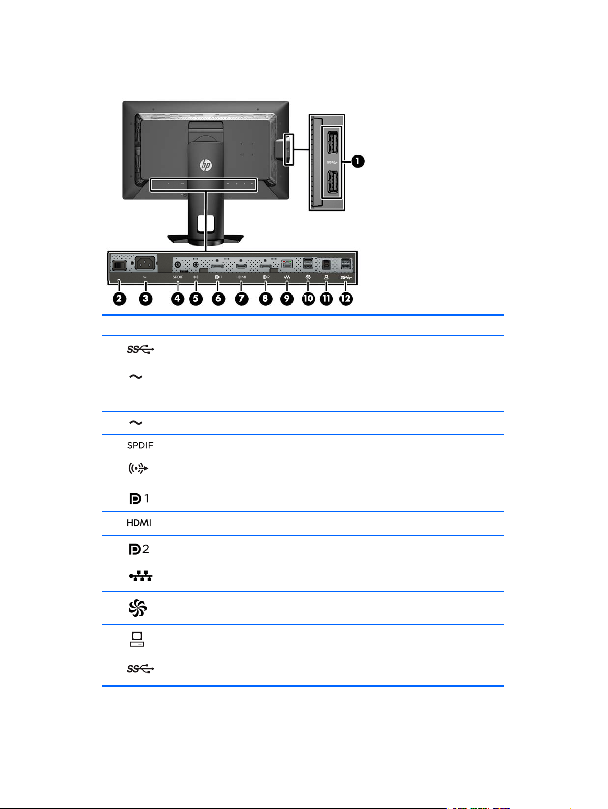
Rear Components
Component Function
1
2
3
4
5
6
7
8
9
10
11
USB 3.0 Downstream
Connectors (side panel)
Master Power Switch Turns off all power to the monitor.
AC Power Connector Connects the AC power cord to the monitor.
Digital Audio Out Connects a digital audio component to the monitor.
Analog Audio Out Connects headphones or optional HP Speaker Bar to the
DisplayPort 1 Connects a DisplayPort cable to the monitor.
HDMI Connects an HDMI cable to the monitor.
DisplayPort 2 Connects a DisplayPort cable to the monitor.
RJ-45 Network
Connector
DreamColor USB 2.0
Ports
USB 3.0 Upstream Port Connects the USB hub cable to the monitor's USB hub
Connects optional USB devices to the monitor.
NOTE: Putting the switch in the Off position will yield the
lowest power state for the monitor when not in use.
monitor.
Connects a network cable to the monitor.
Connects a color calibration instrument or a USB flash
drive for color calibration or firmware update.
connector and to a host USB port/hub.
12
USB 3.0 Downstream
Ports
Connects optional USB devices to the monitor.
Rear Components 7
Page 16
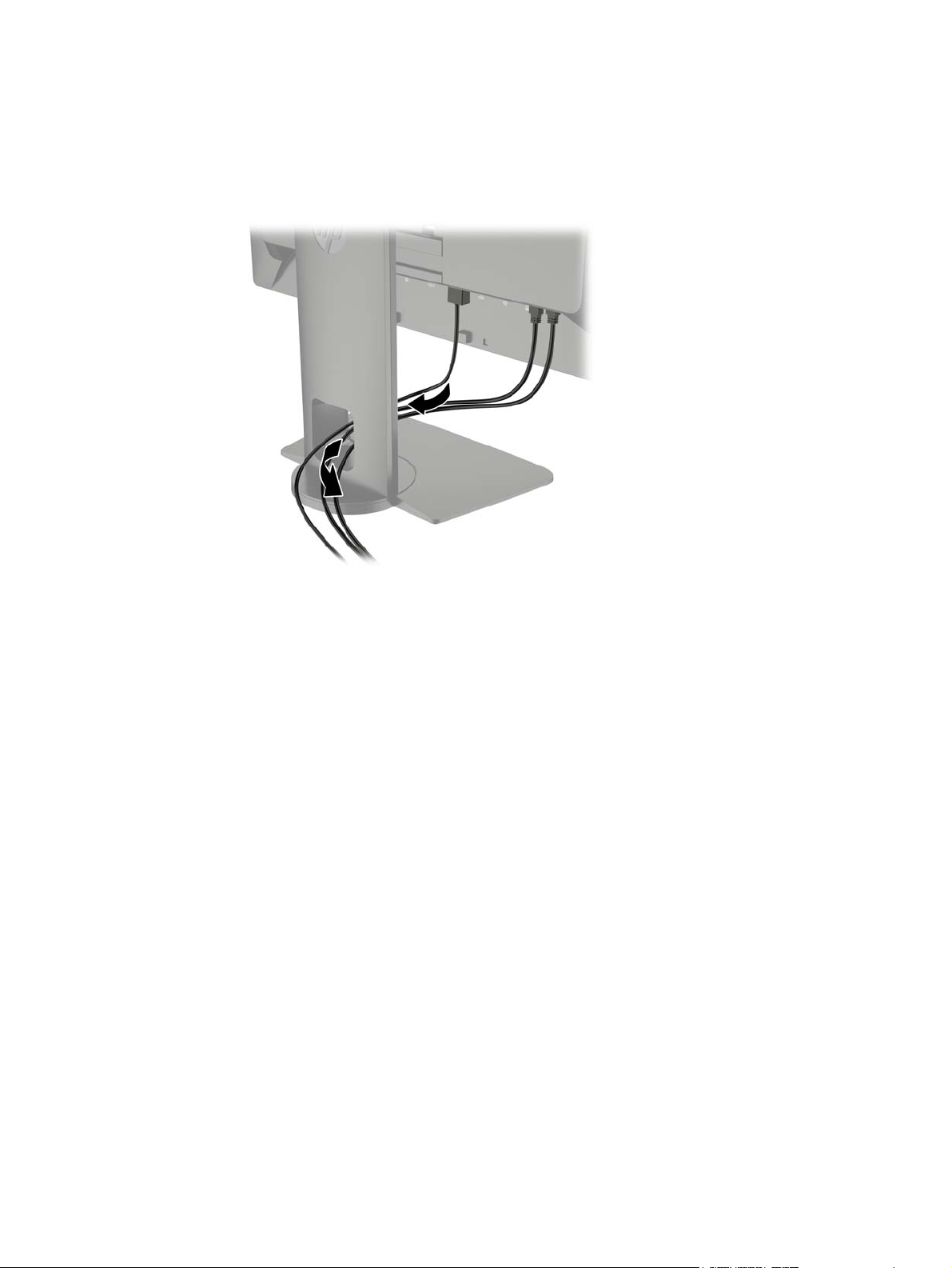
Connecting the Cables
1. Place the monitor in a convenient, well-ventilated location near the computer.
2. Before connecting the cables, route the cables through the cable routing hole in the center of the
stand.
8 Chapter 3 Setting Up the Monitor
Page 17
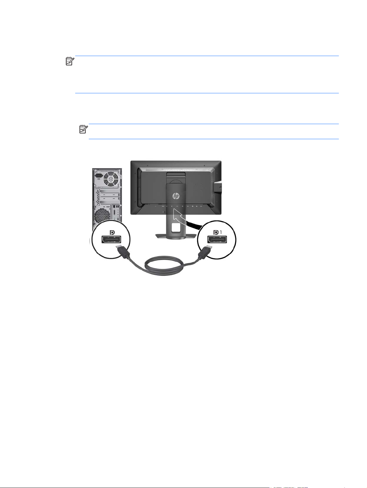
3. Depending on your configuration, connect either the DisplayPort or HDMI video cable between
the PC and the monitor.
NOTE: The video mode is determined by the video cable used. The monitor will automatically
determine which inputs have valid video signals. The inputs can be selected through the OnScreen Display (OSD) feature by pressing one of the five front bezel buttons to activate the
buttons, and then press the bottom Open Menu button to open the OSD. In the OSD select
Video Input and choose the desired input source.
For DisplayPort digital operation, connect the DisplayPort signal cable to the DisplayPort
●
connector on the rear of the monitor and the other end to the DisplayPort connector on the
computer (cable provided).
NOTE: There are two DisplayPort connectors on the rear of the monitor allowing you to
connect two workstations to the monitor.
Connecting the Cables 9
Page 18
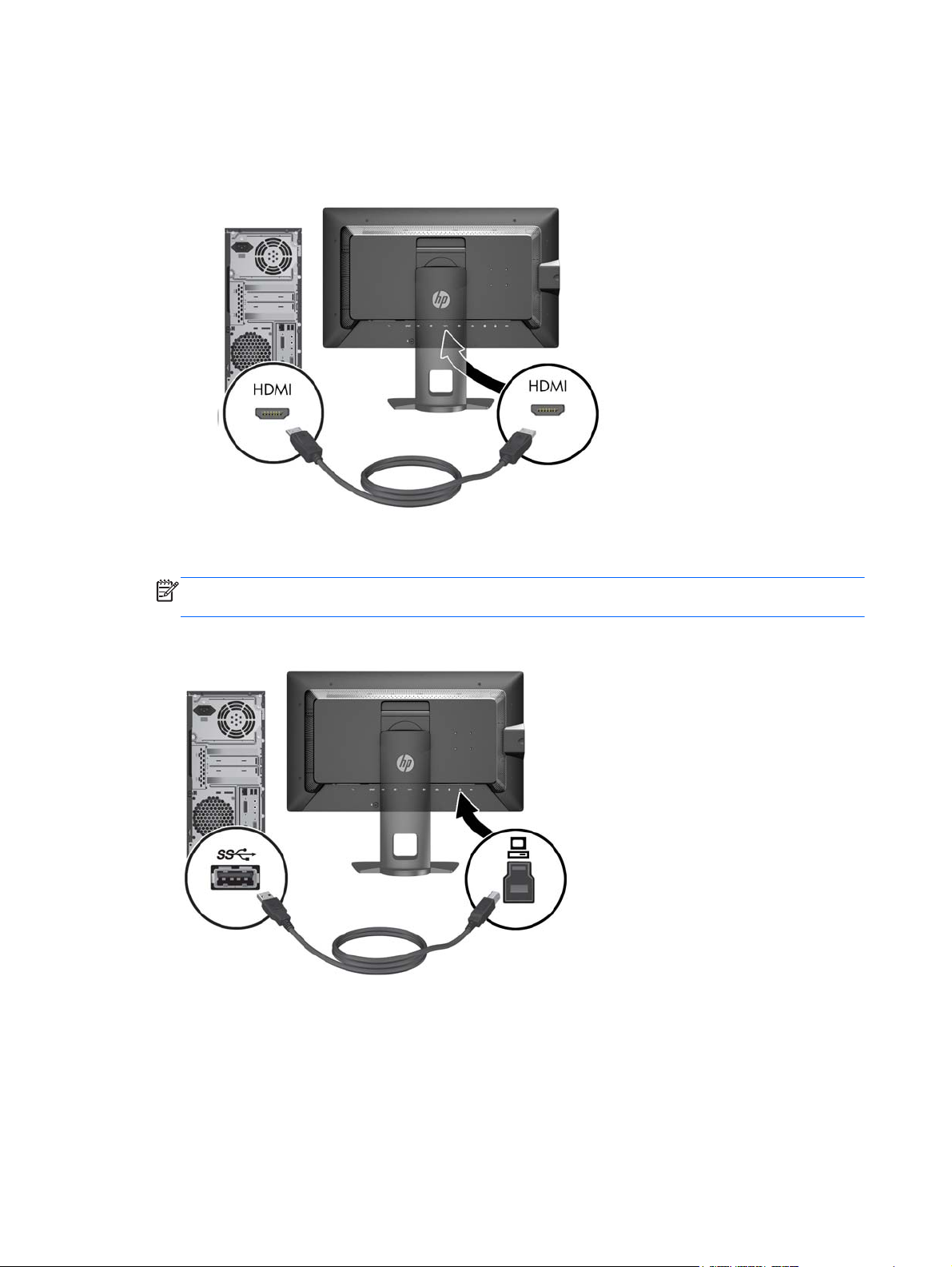
For HDMI digital operation, connect the HDMI signal cable to the HDMI connector on the
●
rear of the monitor and the other end to the HDMI connector on the computer (cable
provided).
4. Connect one end of the provided USB cable to the USB hub connector on the rear panel of the
computer, and the other end to the upstream USB connector on the monitor.
NOTE: The monitor supports USB 3.0. For optimal performance, connect the USB cable to a
USB 3.0 port on the computer, if available.
10 Chapter 3 Setting Up the Monitor
Page 19
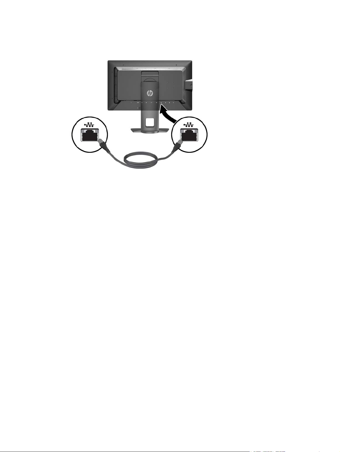
5. Connect a live network connector to the network connector on the rear of the monitor (optional).
Connecting the Cables 11
Page 20
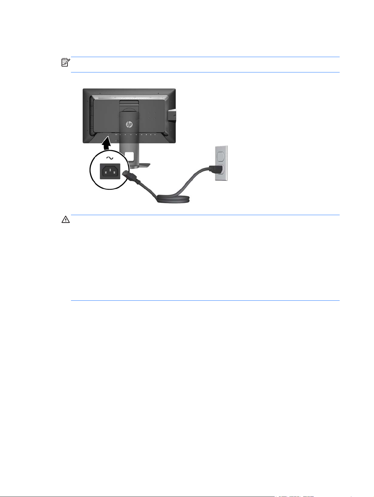
6. Connect one end of the power cord to the AC power connector on the back of the monitor, and
the other end to an electrical wall outlet.
NOTE: The master power switch on the rear of the monitor must be in the On position before
pressing the power button on the front of the monitor.
WARNING! To reduce the risk of electric shock or damage to the equipment:
Plug the power cord into an AC outlet that is easily accessible at all times.
Disconnect power from the computer by unplugging the power cord from the AC outlet.
If provided with a 3-pin attachment plug on the power cord, plug the cord into a grounded
(earthed) 3-pin outlet. Do not disable the power cord grounding pin, for example, by attaching a
2-pin adapter. The grounding pin is an important safety feature.
For your safety, do not place anything on power cords or cables. Arrange them so that no one
may accidentally step on or trip over them. Do not pull on a cord or cable. When unplugging from
the electrical outlet, grasp the cord by the plug.
12 Chapter 3 Setting Up the Monitor
Page 21
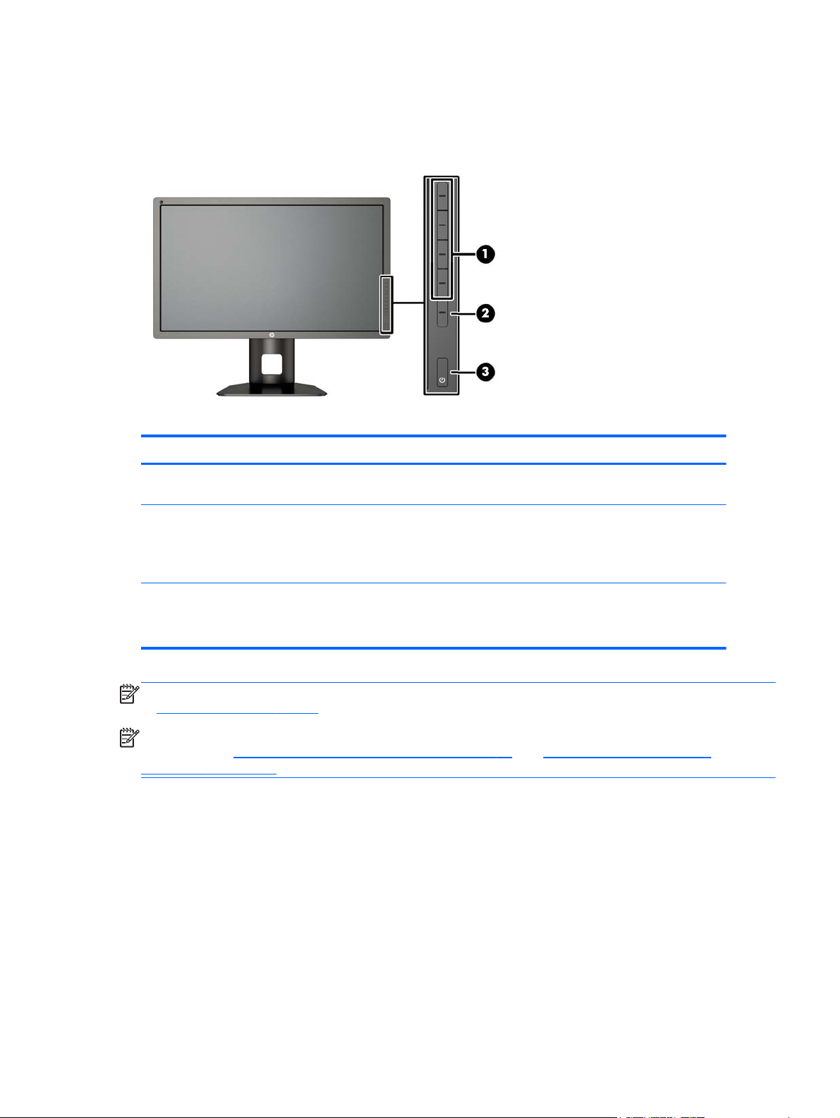
Front Panel Controls
Control Function
1 Function buttons Use these buttons to navigate through the OSD based on the indicators next to
2 Open Menu button Opens and closes the OSD.
3 Power button Turns the monitor on or off.
the buttons that are activated while the OSD is open.
NOTE: To activate the Open Menu button and the Function buttons, press any
of the buttons so that the button labels appear on the right side of the screen and
the button LEDs are lit.
NOTE: Be sure the master power switch on the rear of the monitor is in the ON
position to turn on the monitor.
NOTE: To view an OSD menu simulator, visit the HP Customer Self Repair Services Media Library
http://www.hp.com/go/sml.
at
NOTE: You can adjust the bezel button brightness and change the function of the buttons in the
OSD. Refer to
Adjusting the Bezel Button LEDs on page 43 and Changing the Bezel Button
Functions on page 40 for more information.
Front Panel Controls 13
Page 22
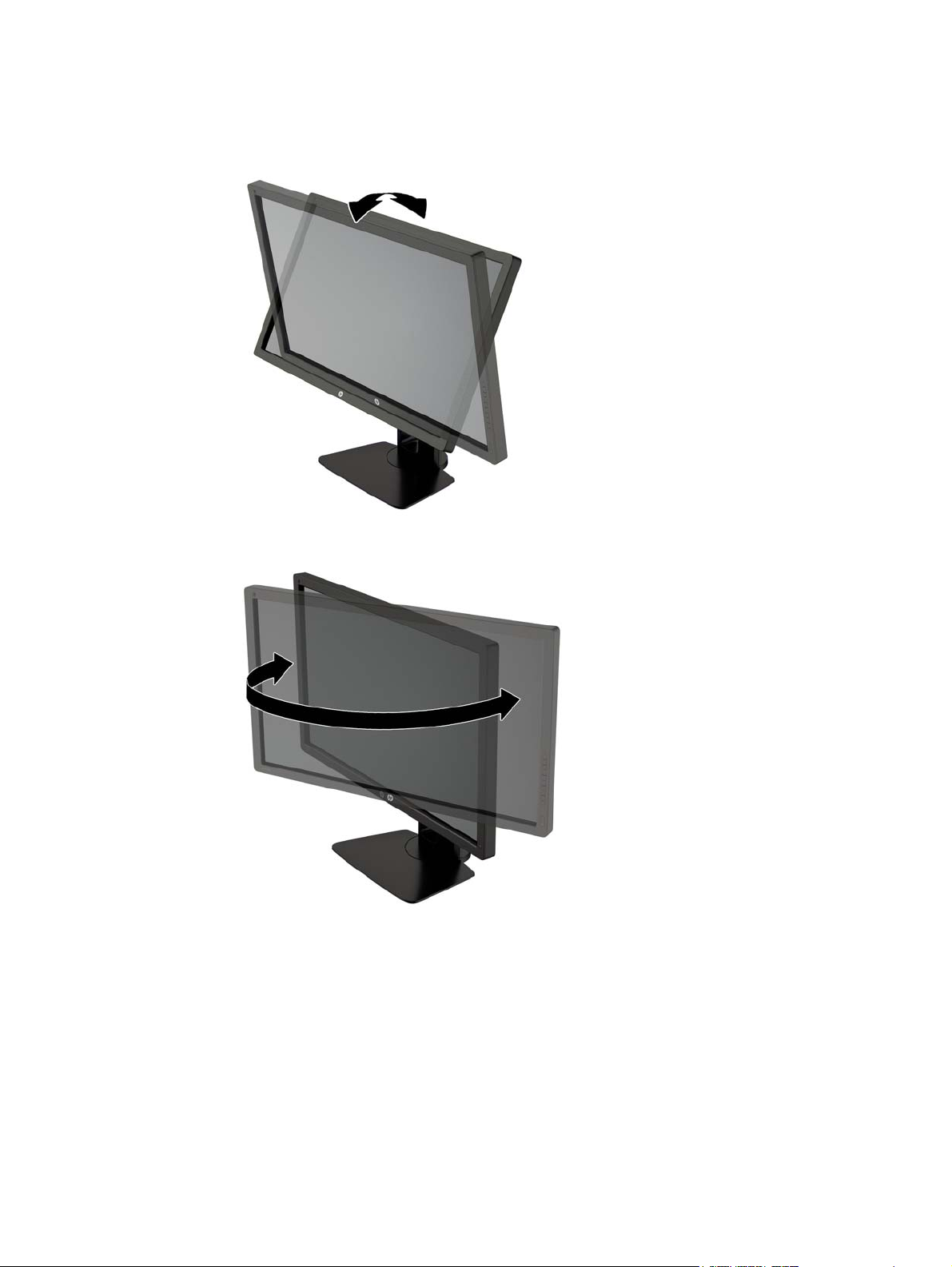
Adjusting the Monitor
1. Tilt the monitor's panel forward or backward to set it to a comfortable eye level.
2. Swivel the monitor to the left or right for the best viewing angle.
14 Chapter 3 Setting Up the Monitor
Page 23
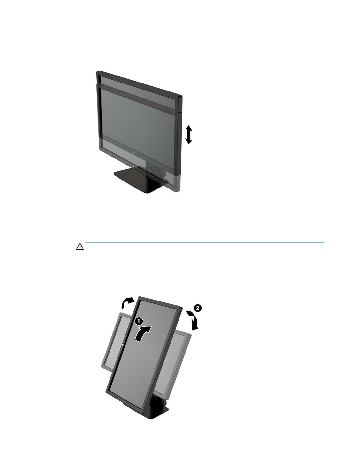
3. Adjust the monitor’s height to a comfortable position for your individual workstation. The
monitor’s top bezel edge should not exceed a height that is parallel to your eye height. A monitor
that is positioned low and reclined may be more comfortable for users with corrective lenses.
The monitor should be repositioned as you adjust your working posture throughout the work day.
4. You can pivot the monitor from landscape to portrait orientation viewing to adapt to your
application.
a. Adjust the monitor to full height position and tilt the monitor back to full tilt position (1).
b. Pivot the monitor clockwise 90° from landscape to portrait orientation (2).
CAUTION: If the monitor is not in full height and full tilt position when pivoting, the bottom
right corner of the monitor panel will come in contact with the base and potentially cause
damage to the monitor.
If you are adding an optional speaker bar to the monitor, install it after pivoting the monitor.
The speaker bar will come in contact with the base when pivoting and potentially cause
damage to the monitor or speaker bar.
Adjusting the Monitor 15
Page 24

NOTE: Use the operating system's display settings to rotate the image on the screen from
portrait to landscape. To rotate the OSD from portrait to landscape, open the OSD and select
Image Adjustment > On-Screen Menu Rotation > Portrait.
16 Chapter 3 Setting Up the Monitor
Page 25

Turning on the Monitor
1. Set the master power switch on the rear of the monitor to the On position.
2. Press the power button on the computer to turn it on.
3. Press the power button on the front of the monitor to turn it on.
CAUTION: Burn-in image damage may occur on monitors that display the same static image on
screen for a prolonged period of time.* To avoid burn-in image damage on the monitor screen, you
should always activate a screen saver application or turn off the monitor when it is not in use for a
prolonged period of time. Image retention is a condition that may occur on all LCD screens. Monitors
with a “burned-in image” are not covered under the HP warranty.
* A prolonged period of time is 12 consecutive hours of a static image.
NOTE: If pressing the power button has no effect, the Power Button Lockout feature may be
enabled. To disable this feature, press and hold the monitor power button for 10 seconds.
When the monitor is powered on, a Monitor Status message is displayed for five seconds. The
message shows which input is the current active signal, the status of the auto-switch source setting
(On or Off; factory default is On), the default source signal (factory default is DisplayPort), the current
preset display resolution, and the recommended preset display resolution.
The monitor automatically scans the signal inputs for an active input and uses that input for the
display. If two or more inputs are active, the monitor will display the default input source. If the default
source is not one of the active inputs, then the monitor will display the highest ranking priority input.
You can select the input source in the OSD. Press one of the five front bezel buttons to activate the
buttons, and then press the bottom Open Menu button to open the OSD. In the OSD select Video
Input and choose the desired input source.
Turning on the Monitor 17
Page 26

HP Watermark and Image Retention Policy
The IPS monitor models are designed with IPS (In-Plane Switching) display technology which
provides ultra-wide viewing angles and advanced image quality. IPS monitors are suitable for a wide
variety of advanced image quality applications. This panel technology, however, is not suitable for
applications that exhibit static, stationary or fixed images for long periods of time without the use of
screen savers. These types of applications may include camera surveillance, video games, marketing
logos, and templates that are displayed on the screen for a prolonged period of time. Static images
may cause image retention damage that could look like stains or watermarks on the monitor's screen.
Monitors in use for 24 hours per day that result in image retention damage are not covered under the
HP warranty. To avoid image retention damage, always turn off the monitor when it is not in use or
use the power management setting, if supported on your system, to turn off the display when the
system is idle.
Connecting USB Devices
There are four downstream USB ports on the monitor (two on the rear and two on the side).
NOTE: You must connect the USB hub cable from the monitor to the computer to enable the USB
ports on the monitor. Refer to Step 4 in
Connecting the Cables on page 8.
Removing the Monitor Stand
You can remove the monitor panel from the stand to install the panel on a wall, a swing arm, or other
mounting fixture.
CAUTION: Before beginning to disassemble the monitor, be sure the monitor is turned off and the
power, signal, and network cables are all disconnected. Also disconnect all USB cables connected to
the monitor.
1. Disconnect and remove all cables from the monitor.
2. Lay the monitor face down on a flat surface covered by a clean, dry cloth.
3. Press down on the latch near the bottom center of the monitor to unlock the HP Quick Release 2
(1).
18 Chapter 3 Setting Up the Monitor
Page 27

4. Swing the bottom of the stand up until the mounting plate clears the recess in the panel (2).
5. Slide the stand out of the recess (3).
Mounting the Monitor
The monitor panel can be attached to a wall, swing arm, or other mounting fixture.
You can attach the monitor panel to a mounting fixture using the HP Quick Release 2 mounting
bracket or you can attach the monitor panel to a mounting fixture without the HP Quick Release 2
mounting bracket.
NOTE: This apparatus is intended to be supported by UL or CSA Listed wall mount bracket.
CAUTION: This monitor supports the VESA industry standard 100 mm mounting holes. To attach a
third-party mounting solution to the monitor, four 4 mm, 0.7 pitch, and 10 mm long screws are
required. Longer screws must not be used because they may damage the monitor. It is important to
verify that the manufacturer’s mounting solution is compliant with the VESA standard and is rated to
support the weight of the monitor display panel. For best performance, it is important to use the power
and video cables provided with the monitor.
Mounting the Monitor 19
Page 28

Mounting the Monitor Using the Quick Release 2 Mounting Bracket
To mount the monitor panel to a mounting fixture using the Quick Release 2 mounting bracket:
1. Remove the four screws holding the mounting plate to the head of the stand.
2. Remove the four screws from the mounting plate to separate the mounting plate from its cover.
20 Chapter 3 Setting Up the Monitor
Page 29

3. Remove the four screws from the VESA holes located on the rear of the monitor panel.
4. Install the mounting plate to the wall or swing arm of your choice using the four screws that were
removed from the VESA holes on the rear of the monitor panel.
Mounting the Monitor 21
Page 30

5. Place the monitor panel on the mounting bracket you've installed by aligning its recess with the
mounting bracket, then sliding it down over the top of the bracket and pressing it back into place
against the bracket. The release latch on the monitor will pop up when the monitor is safely
locked in place.
22 Chapter 3 Setting Up the Monitor
Page 31

Mounting the Monitor Without Using the Quick Release 2 Mounting Bracket
To mount the monitor panel directly to a mounting fixture without using the HP Quick Release 2
mounting bracket, use the four screws removed from the VESA holes on rear of the monitor panel
and install them to attach the mounting device to the rear of the monitor panel.
Installing an Optional HP Hood Kit
The HP LCD Hood Kit is a monitor option designed to block the glare from overhead lighting. The
hood helps to improve the color and contrast performance of the monitor in a room with bright
overhead lights.
Shields the display from ambient light
●
Reduces on-screen glare from surrounding office lighting and windows
●
Improves the monitor color and contrast performance
●
1. Assemble the hood according to the instructions included with the kit.
Installing an Optional HP Hood Kit 23
Page 32

2. Remove the plugs that cover the screw holes for the hood.
NOTE: You may need to use a small screwdriver to pry the plugs out.
3. Secure the hood to the monitor using the screws included in the kit.
24 Chapter 3 Setting Up the Monitor
Page 33

Locating the Serial Number and Product Number
The serial number and product number are located on a label on the rear panel of the display head.
You may need these numbers when contacting HP about the monitor model.
NOTE: You may need to partially pivot the display head to read the label.
Locating the Information Card
Identifying information is located on the pull-out card (and included on a label on the back of the
monitor). The card pulls out from behind the USB connectors on the left side of the panel. Warranty
support information (model number, serial number, product number) is printed on the front of the card
(and the label) and regulatory information is printed on the back of the card.
Locating the Serial Number and Product Number 25
Page 34

Attaching a Device to the Rear of the Monitor
The rear of the monitor has four 40mm X 40mm VESA standard mounting holes that can be used to
mount a device.
1. Remove the plugs from the VESA mounting holes on the rear of the monitor.
NOTE: You may need to use a small screwdriver to pry the plugs out.
2. Mount the device to the rear of the monitor.
26 Chapter 3 Setting Up the Monitor
Page 35

Installing a Cable Lock
You can secure the monitor to a fixed object with an optional cable lock available from HP.
Installing a Cable Lock 27
Page 36

4 Operating the Monitor
Software and Utilities
The disc that comes with the monitor contains files you can install on the computer:
an .INF (Information) file
●
ICM (Image Color Matching) files (one for each calibrated color space)
●
client and server certificates for remote management via the Z27x web interface
●
Z27x USB Software Development Kit (SDK) for Linux, Windows, and Mac
●
sample StudioCal XML calibration files
●
NOTE: If the monitor does not include a disc, the items listed above can be downloaded from the
HP monitors support Web site. See
The Information File
The .INF file defines monitor resources used by Microsoft Windows operating systems to ensure
monitor compatibility with the computer’s graphics adapter.
This monitor is Microsoft Windows Plug and Play compatible and the monitor will work correctly
without installing the .INF file. Monitor Plug and Play compatibility requires that the computer’s
graphic card is VESA DDC2–compliant and that the monitor connects directly to the graphics card.
Plug and Play does not work through separate BNC type connectors or through distribution buffers/
boxes.
Downloading from the Internet on page 29 in this chapter.
The Image Color Matching File
The .ICM files are data files that are used in conjunction with graphics programs to provide consistent
color matching from monitor screen to printer, or from scanner to monitor screen. This file is activated
from within graphics programs that support this feature.
NOTE: The ICM color profile is written in accordance with the International Color Consortium (ICC)
Profile Format specification.
28 Chapter 4 Operating the Monitor
Page 37

Installing the .INF and .ICM Files
After you determine that you need to update, you can install the .INF and .ICM files from the disc or
download them.
Installing from the Disc
To install the .INF and .ICM files on the computer from the disc:
1. Insert the disc in the computer optical drive. The disc menu is displayed.
2. View the HP Monitor Software Information file.
3. Select Install Monitor Driver Software.
4. Follow the on-screen instructions.
5. Ensure that the proper resolution and refresh rates appear in the Windows Display control panel.
NOTE: You may need to install the digitally signed monitor .INF and .ICM files manually from the
disc in the event of an installation error. Refer to the HP Monitor Software Information file on the disc.
Downloading from the Internet
To download the latest version of .INF and .ICM files from the HP monitors support Web site:
1. Go to
2. Select the Drivers & Downloads link then enter Z27x in the search box and click the Go button.
3. Select your model then select your language and operating system.
4. Download the software by following the instructions.
http://www.hp.com/support and select the appropriate country and language.
Updating the Firmware
HP recommends that you check for updated display firmware and install newer firmware if available.
NOTE: By default, the monitor’s internal processor – which is required for firmware updating – is
disabled. You must enable the processor before you can update the monitor firmware. In the OSD
select Management > Manage Internal Processor and choose Enable to turn the processor on. If
turning on just before attempting to update the firmware, wait approximately one minute for the
internal processor to fully boot.
Installing the .INF and .ICM Files 29
Page 38

To update the firmware via USB:
1. Check your current firmware version.
a. Press any button on the front bezel.
b. Press the bottom Open Menu button to open the OSD.
c. Select Information to view the current firmware version.
TIP: A bezel button shortcut, Display Info..., is provided on the fourth bezel button in the
Z27x factory configuration. You can access this information page via this shortcut, unless
the bezel button has been remapped.
2. Find the latest firmware on the Web.
a. Go to
http://www.hp.com/support and select the country region.
b. Select the Drivers & Downloads link then enter Z27x in the search box and click the Go
button.
c. Select your model then select your language and operating system.
d. Check the latest firmware revisions listed for “HP Z27x Firmware Update” to see if it is a
newer version than what is currently installed.
e. Download the firmware onto a USB flash drive. The following USB drive formats are
supported: FAT, FAT32, NTFS.
3. Insert the USB flash drive with the latest firmware into one of the DreamColor USB ports and
follow the onscreen instructions to install the firmware.
NOTE: The firmware is distributed as a compressed, signed tar file. Do not decompress the file
before installing.
CAUTION: The monitor screen will turn black during the installation and the front panel LED
will flash amber. Do not turn off the monitor during the firmware update.
30 Chapter 4 Operating the Monitor
Page 39

Selecting a Color Space Preset
The Z27x provides factory calibrated color space presets, suitable for a wide variety of color-critical
workflows including visual effects, animation, on-set/dailies viewing, professional photography,
product design, print/pre-press, graphic arts, and many others. Five industry standard color spaces
are provided along with two different ways to access the display’s native color gamut. The following
table provides information on the five provided standard color spaces.
Preset Name Red Primary
(u’v’)
sRGB 0.451, 0.523 0.125, 0.563 0.175, 0.158 D65 sRGB
AdobeRGB 0.451, 0.523 0.076, 0.576 0.175, 0.158 D65 2.2
BT.709 0.451, 0.523 0.125, 0.563 0.175, 0.158 D65 2.4
BT.601 0.432, 0.525 0.130, 0.562 0.175, 0.158 D65 2.4
BT.2020 0.557, 0.516 0.056, 0.587 0.159, 0.126 D65 2.4
DCI P3 0.496, 0.526 0.099, 0.578 0.175, 0.158 P3 2.6
Green Primary
(u’v’)
Blue Primary
(u’v’)
White Point Gamma Luminance
250 cd/m
250 cd/m
100 cd/m
100 cd/m
100 cd/m
48 cd/m
2
2
2
2
2
2
In addition, the Native preset provides access to the display’s native color gamut. This preset has
also been calibrated to have a D65 white point and a 2.2 gamma.
To select a color space preset:
1. Press any button on the front bezel.
2. Press the bottom Open Menu button to open the OSD.
3. Select Color Space to display the color space configuration screen.
4. Use the Up/Down buttons to navigate to the desired color space then press the Select button to
activate it.
Adjusting Luminance
Though each preset is calibrated to a specific luminance level, the luminance can be adjusted postcalibration. The luminance range for all calibrated color space presets can be adjusted from 48–250
2
. The Native preset can be adjusted from 0–100% of maximum display luminance.
cd/m
NOTE: Due to the way LEDs respond to voltage, the further you adjust luminance away from the
calibrated value, the less-accurate the luminance value reported by the OSD will be. HP recommends
that you calibrate your monitor to the desired working luminance.
To adjust luminance:
1. Press any button on the front bezel.
2. Press the bottom Open Menu button to open the OSD.
3. Select Color Space to display the color space configuration screen.
4. Use the Up/Down buttons to navigate to the Adjust Luminance option then press the Select
button to activate it.
5. Use the Increase/Decrease buttons to adjust the luminance to the desired level.
Selecting a Color Space Preset 31
Page 40

NOTE: The Adjust Luminance option displays the current luminance value to the right of the menu
option.
Understanding the Z27x Image Adjustment Options
The Z27x contains a number of special image adjustment options that are designed to fit specific
workflows in the media and entertainment industry. The following section describes these functions
from the perspective of their application in these workflows.
Use Video Levels (16–235)
This option is designed to support the accurate display of video signals that include footroom below
black and headroom above white. These types of signals are typically encountered when working
with video signals that conform to the complete ITU-R BT.709 or ITU-R BT.601 standards as these
standards allow for excursions beyond black and white, rather than treating black and white as
absolutes.
These signals are typically encountered in the following situations:
Viewing the HDMI or HD-SDI output from a video capture and playback card such as an AJA
●
Kona or Blackmagic Design DeckLink
Viewing an image in the Composer/Edit/Preview window in a non-linear video editing program
●
Viewing the output of a consumer Blu-Ray/DVD player
●
In all of these situations the video signal usually includes the BT.709/BT.601 headroom and footroom.
Without this option enabled when viewed in a computer monitor the blacks and shadows are lighter,
the whites are darker, and colors have less saturation than the signal actually contains.
When this option is enabled the blacks will be clipped at the 8-bit value of 16 and the whites at the 8bit value of 235 (for 10-bit, the clipping will occur at the values of 64 and 960). The signal is then
remapped to display the signal in the correct visual range.
It is important to note that the source and pre-processing of the source video will impact whether this
setting should be enabled, but in many cases you will see a more-accurate image if you enable this
option. Note that you may need to adjust the lightness of your editing application interface after
enabling this setting.
To use video levels:
1. Press any button on the front bezel.
2. Press the bottom Open Menu button to open the OSD.
3. Select Image Adjustment to display the adjustment options screen.
4. Use the Up/Down buttons to navigate to the Use Video Levels option then press the Select
button to select it. The option will be checked when it is active.
Overscan the Frame
Though by default the Z27x displays all pixels in the image, when screening video dailies or an edit
revision it may be desirable to view the image in an overscanned mode, similar to how it is viewed on
a consumer digital television. The Overscan Frame by 5% option will enlarge the image so that only
that portion of the frame within the Action Safe region is displayed. Action Safe is defined as an area
that begins 5% inside the edge of the frame.
32 Chapter 4 Operating the Monitor
Page 41

To use video levels:
1. Press any button on the front bezel.
2. Press the bottom Open Menu button to open the OSD.
3. Select Image Adjustment to display the adjustment options screen.
4. Use the Up/Down buttons to navigate to the Overscan Frame by 5% option then press the
Select button to select it. The option will be checked when it is active.
Show Only the Blue Channel
As the human is least-sensitive to changes in blue, most compression and encoding algorithms
assign the least amount of bandwidth to the blue channel. Because of this, compression/encoding
errors are most-easily seen when viewing the blue channel. The Z27x allows the user to view just the
blue channel, temporarily turning the red and green channels off, so that the image can be inspected
for these errors.
To view only the blue channel:
1. Press any button on the front bezel.
2. Press the bottom Open Menu button to open the OSD.
3. Select Image Adjustment to display the adjustment options screen.
4. Use the Up/Down buttons to navigate to the Show Blue Channel Only option then press the
Select button to select it. The option will be checked when it is active.
Using the Z27x Aspect Ratio Management Options
The Z27x includes a number of special aspect ratio management options that go far beyond what is
typically found in a computer monitor. This section discusses these options, with a focus of how these
options are integrated into specific workflows.
The “Fill To” Options
These options are used to determine how the source input is displayed onscreen if its resolution is
different from the monitor’s native resolution of 2560×1440.
Fill to Source Aspect Ratio (Proportional)
This option will maintain the aspect ratio of the source input, making the image as large as possible,
centering it in the monitor, and using 0% black to fill the unused areas of the screen. For example, a
source input that is narrower than 16×9 will be displayed at full height with black bars to the left and
right of the source image, and a source input that is wider than 16×9 will be the displayed at full width
with black bars above and below the source image.
Fill to Source Aspect Ratio is the default and is the option most-suitable to the majority of workflows.
Fill to Entire Screen (Non-Proportional)
This option will distort non-16×9 source aspect ratios to force them to fit within the monitor’s 16×9
aspect ratio. The resulting image will take up the entire display and will either be stretched
horizontally (for narrower aspect ratios) or vertically (for wider aspect ratios).
Use Fill to Entire Screen if the source aspect ratio is irrelevant and you want the entire screen to be
filled, regardless of the distortion that may be caused.
Using the Z27x Aspect Ratio Management Options 33
Page 42

Fill to Screen Width (Proportional)
This option is to be used for specific workflows with source video that is narrower than the monitor’s
native 16×9 aspect ratio. In some film workflows it is desired to render the animation or visual effects
at a 4×3 aspect ratio and perform a “center extraction” for widescreen delivery. If enabled, this option
will resize the source image so that the width matches the monitor width. Then the source image is
centered vertically and the top and bottom of the image are cropped off, leaving a 16×9 “center
extraction” of the 4×3 frame. The proportions of the source image are maintained.
The Fill to Screen Width option should be used when vertical center extractions are desired as part of
the dailies or review screening process.
Fill to Screen Height (Proportional)
This option is to be used for specific workflows with source video that is wider than the monitor’s
native 16×9 aspect ratio. In some film workflows it is desired to see a 16×9 horizontal extraction of a
wider source aspect ratio. If enabled, this option will resize the source image so that the height
matches the monitor height. Then the source image is centered horizontally and the top and bottom
of the image are cropped off, leaving a 16×9 “center extraction” of the wider frame. The proportions of
the source image are maintained.
The Fill to Screen Height option should be used when horizontal center extractions are desired as
part of the dailies or review screening process.
Pixel-for-Pixel
This option is to be used for source video that has a lower resolution than the monitor’s native
resolution of 2560×1440 and you wish to view the image without any scaling applied. For example, if
your source image has a 1920×1080 resolution and you wish to inspect the pixels to ensure that
there are no rendering issues in the displayed content, you may want to use this option.
This option has a specific functionality when the source video has a higher resolution than
2560×1440. This functionality will be covered in the next section.
“Fill To” Examples
The following illustrations summarize how a 4×3 source image is displayed using the “Fill to” options.
The Fill to Screen Height option is not applicable to this source aspect ratio so it is not shown.
Figure 4-1 4×3 Input Source
34 Chapter 4 Operating the Monitor
Page 43

Figure 4-2 Fill to Aspect Ratio
Figure 4-3 Fill to Entire Screen
Figure 4-4 Fill to Screen Width
Using the Z27x Aspect Ratio Management Options 35
Page 44

Figure 4-5 Pixel-for-Pixel
To change the way the source video is displayed onscreen:
1. Press any button on the front bezel.
2. Press the bottom Open Menu button to open the OSD.
3. Select Image Adjustment to display the adjustment options screen.
4. Select Aspect Ratio Display to display the display options.
5. Use the Up/Down buttons to navigate to the desired open option then press the Select button to
select it.
NOTE: The Aspect Ratio Display page can be mapped to a bezel button function key for easy
access. Refer to
Changing the Bezel Button Functions on page 40 for instructions on mapping the
bezel button function keys.
Working with 2K and 4K Digital Cinema Image Formats
The Z27x has direct support for the 2048×1080 and 4096×2160 image formats (containers) as
specified in the Digital Cinema Initiatives (DCI) - Digital Cinema System Specification. The following
table lists the supported formats.
DCI Level Horizontal Pixels Vertical Pixels Frame Rate
1 4096 2160 24.00
2 2048 1080 48.00
3 2048 1080 24.00
TBD* 2048 1080 60.00
* At the time of this document’s release, the 60.00 fps 2K format has not yet been formally codified by the DCI. Support for it
has been included in the Z27x in anticipation of future use and codification.
In addition, the display supports aspect ratio masking for the two standard aspect ratios, 1.85:1 and
2.39:1, within the DCI image container. When DCI aspect ratio masking is selected the source video
is masked to only show the pixels within the specified aspect ratio. The following table lists the active
pixels that will be displayed for each image container and aspect ratio.
DCI Container Size Aspect Ratio Horizontal Active Pixels Vertical Active Pixels
4096 × 2160 1.85:1 3996 2160
36 Chapter 4 Operating the Monitor
Page 45

DCI Container Size Aspect Ratio Horizontal Active Pixels Vertical Active Pixels
4096 × 2160 2.39:1 4096 1716
2048 × 1080 1.85:1 1998 1080
2048 × 1080 2.39:1 2048 858
Finally, special display modes for 4K input resolutions are also provided to facilitate the display of 4K
content on the Z27x.
Using the Digital Cinema Display Options
All of the digital cinema display options are located in the OSD on the Main Menu > Image
Adjustment > Aspect Ratio Display page. These options are unavailable and the menu option
dimmed unless one of the following resolutions is being displayed via the active video input:
2048 × 1080
●
4096 × 2160
●
● 3840 × 2160
NOTE: Though the Digital Cinema Options menu is available for the 3840 × 2160 resolution, the
aspect ratio options are not available because 3840 × 2160 is not a DCI container size.
To access the digital cinema display options:
1. Connect a computer or video device to the monitor that is configured to output a 2048 × 1080 or
4096 × 2160 resolution.
2. Press any button on the front bezel.
3. Press the bottom Open Menu button to open the OSD.
4. Select Image Adjustment to display the adjustment options screen.
5. Select Aspect Ratio Display to display the display options.
6. Select Digital Cinema Options to display the digital cinema options.
The following DCI Aspect Ratio options are available in the Image Region section of the Digital
Cinema Options page.
Show Entire DCI Container
This is the default option and will show the entire DCI 2048 × 1080 or 4096 × 2160 frame.
Crop to DCI 1.85:1 Aspect Ratio
This option crops 25 pixels from the left and right edges of the frame (for 2048-wide sources, 50
pixels from the left and right edges for 4096-wide sources). The resultant image is then displayed as
specified using the Aspect Ratio Display options described in the previous section.
Crop to DCI 2.39:1 Aspect Ratio
This option crops 111 pixels from the top and bottom edges of the frame (for 2048-wide sources, 222
pixels from the top and bottom edges for 4096-wide sources). The resultant image is then displayed
as specified using the Aspect Ratio Display options described in the previous section.
Working with 2K and 4K Digital Cinema Image Formats 37
Page 46

Show Cropped Region
When this option is enabled, rather than cropping and resizing the image to the selected aspect ratio,
the image is not resized, but the region outside the desired aspect ratio is instead overlaid with a
partially-transparent black mask. This option is useful, for example to check the top line in a 2.39:1
aspect ratio and see what information may be available, if the headroom needs to be adjusted via
reframing.
Set Cropped Region Opacity
This option is available when Show Cropped Region is active and allows you to specify the amount of
opacity applied to the cropped region. Adjust as needed to achieve the desired balance between the
active and cropped regions of the frame.
Displaying 4K Source Video
Though it only has a native resolution of 2560 × 1440, the Z27x can receive and display a 4096 ×
2160 or 3840 × 2160 input signal. Multiple scaling and display options are provided. To provide the
highest quality display of 4K source video on the Z27x the scaling algorithm has been specifically
tuned to provide a naturalistic scaling without any sharpness or edge enhancement.
When a 4096 × 2160 or 3840 × 2160 signal is input into the monitor, the following scaling options are
available via the 4K Sources section of the Digital Cinema Options page. If DCI aspect ratio cropping
has been selecting, these options are applied after the image is cropped.
Obey Aspect Ratio Display Option
This default option will display the image according to the selected “Fill to” Aspect Ratio Display
option. Refer to
these options.
Using the Z27x Aspect Ratio Management Options on page 33 for information on
Scale and Show Center Extraction
If selected, the center 16×9 region of the frame will be displayed with the areas outside of this center
region cropped, similar to the Fill to Screen Height option discussed previously. The amount of the
image shown in the center extraction is dependent on whether the entire container or an aspect ratio
is displayed.
Scale and Show Left Side of Frame
If selected, the left-most 16×9 region of the frame will be displayed with the areas outside of this left
side region cropped, similar to the Fill to Screen Height option discussed previously. The amount of
the image shown in the left extraction is dependent on whether the entire container or an aspect ratio
is displayed.
Scale and Show Right Side of Frame
If selected, the right-most 16×9 region of the frame will be displayed with the areas outside of this
right side region cropped, similar to the Fill to Screen Height option discussed previously. The amount
of the image shown in the right extraction is dependent on whether the entire container or an aspect
ratio is displayed.
Show 4K Source Video Pixel-for-Pixel
If the Aspect Ratio Display is set to Pixel-for-Pixel and the 4K Source option is set to Obey Aspect
Ration Display Option, 4096 × 2160 and 3840 × 2160 source video can be displayed pixel-for-pixel.
Two different display options are available, Show 4K Corner and Scroll 4K Region. Accessing these
38 Chapter 4 Operating the Monitor
Page 47

two options require that a specific function be mapped to one of the four bezel function buttons. Refer
Changing the Bezel Button Functions on page 40 for information on mapping the bezel function
to
buttons. The following sections describe the usage of these two options.
Next 4K Corner
When viewing a 4K source as pixel-for-pixel, press the Next 4K Corner button to move, in order,
between the following five positions:
● Center of the frame
Top left corner
●
Top right corner
●
Bottom left corner
●
Bottom right corner
●
The image will continue to switch between the five positions for each button press until Pixel-for-Pixel
display is disabled.
Scroll 4K Region
When viewing a 4K source as pixel-for-pixel, press the Scroll 4K Region button to display navigation
arrows, allowing you to move around the frame to the desired area.
Using Picture-in-Picture (PIP) and Picture-beside-Picture (PBP)
The monitor supports both PIP, where one source is overlaid over another, and PBP, where one
source is positioned adjacent to one another either horizontally (for landscape orientation) or vertically
(for portrait orientation).
To use PIP or PBP:
1. Connect a secondary input source to the monitor.
2. Press one of the five front bezel buttons to activate the buttons, and then press the bottom Open
Menu button to open the OSD.
3. In the OSD, select PIP Control > PIP On/Off and then select either Picture-in-Picture or
Picture-beside-Picture.
4. The monitor will scan the secondary inputs for a valid input and use that input for the PIP/PBP
picture. If you want to change the PIP/PBP input, select PIP Input in the OSD and select the
desired input (DisplayPort 1, DisplayPort 2, or HDMI).
5. If you want to change the size of the PIP, select PIP Size in the OSD then select either Enlarge,
Reduce, Set to Maximum Size, Set to Minimum Size, or Reset to Default Size. At maximum
size, the PIP will display pixel-for-pixel all input formats up to 2048 × 1080. This is to facilitate
using the PIP as a confidence monitor. Please refer to the following section for more information
on this usage.
6. If you want to adjust the position of the PIP, select PIP Position in the OSD, then select either
Top Left, Top Right, Bottom Left, Bottom Right, or Fine Tune Position.
Using Picture-in-Picture (PIP) and Picture-beside-Picture (PBP) 39
Page 48

Using PIP as a Confidence Monitor
As the PIP is primarily designed to be used at as a confidence monitor – at 100% size for 1080- or
720-line content, including DCI 2K content – many of the Image Adjustments available for the main
input are also available for use within the PIP. Refer to
Options on page 32 and Working with 2K and 4K Digital Cinema Image Formats on page 36 for
further information on these adjustments.
The following adjustments are available within the PIP. None are enabled by default.
Use Video Levels (16–235)
If monitoring a video signal output from a video capture card such as an AJA Kona or Blackmagic
Design Decklink, this option should usually be enabled as video levels are typically used in video
post-production workflows.
Overscan Within PIP
Use this option if you wish to see how your video output will be displayed on a consumer television.
This is especially useful when ensuring that the margins for lower third graphics are correct and
nothing will be cut off on a consumer television.
Digital Cinema Options
If you display a 2048 × 1080 signal as a PIP, you can instruct the monitor to display either the full DCI
container or crop the PIP to either the 1.85:1 or 2.39:1 aspect ratio. If cropping to an aspect ratio, the
shape of the PIP will change to the chosen aspect ratio. Black bars will not be visible at the edges of
the PIP.
Understanding the Z27x Image Adjustment
Changing the Bezel Button Functions
You can change the top-level front bezel button functions from their default values so that when the
buttons are activated you can quickly access commonly used commands.
The following commands can be mapped:
Color Space Select – displays a list of available color space presets. Use to quickly switch from
●
one color space preset to another. This command is mapped to Function Button One by default.
Adjust Luminance – allows you to quickly change the monitor luminance. This command is
●
mapped to Function Button Three by default.
Video Input Select – displays a list of the available video inputs so you can switch to another
●
input, as required. This command is mapped to Function Button Two by default.
Switch to Next Active Video Input – use this command to quickly switch between all active video
●
inputs. An active input is defined as one that is receiving a signal from a computer or other video
source.
Aspect Ratio Display – displays the Aspect Ratio Display sub-menu, providing quick access to
●
this set of functions.
● Video Levels (16–235) On / Off – allows you to quickly switch between full range and reduced
range video inputs. When disabled this command will be displayed as “Video Levels (16–235)
On” and when enabled this command will be displayed as “Video Levels (16–235) Off.”
Overscan On / Off – allows you to quickly enable and disable video overscan. When disabled
●
this command will be displayed as “Overscan On” and when enabled this command will be
displayed as “Overscan Off.”
40 Chapter 4 Operating the Monitor
Page 49

Blue-Only Mode On / Off – allows you to quickly enable and disable blue-only display. When
●
disabled this command will be displayed as “Blue-Only Mode On” and when enabled this
command will be displayed as “Blue-Only Mode Off.”
Scroll 4K Region – use this option to scroll through a 4K image being displayed Pixel-for-Pixel.
●
Refer to
command.
Next 4K Corner– use this option to hop from location 4K image being displayed Pixel-for-Pixel to
●
another. Refer to
command.
PIP On / Off – allows you to quickly turn the PIP on and off and is designed to facilitate using it
●
as a confidence monitor. When disabled this command will be displayed as “PIP On” and when
enabled this command will displayed as “PIP Off.” Refer to
on page 40 for more information on this usage.
● Swap Primary / PIP Inputs – use this option to quickly swap the Primary and PIP inputs. Use of
this option does not require that the PIP be enabled, just that the PIP input be configured.
Therefore this option can be used as another method of quickly switching between two inputs.
Next PIP Corner – use this option to move the PIP from position to position on the screen.
●
Repeated use of this command will fly the PIP in the following order: Upper Left Corner, Upper
Right Corner, Lower Left Corner, Lower Right Corner.
Show Display information – this command will display useful display information including
●
Display Mode, Active Color Space, Monitor Serial Number, Firmware Revision, and Backlight
Hours. This command is mapped to Function Button Four by default.
Show 4K Source Video Pixel-for-Pixel on page 38 for more information on this
Show 4K Source Video Pixel-for-Pixel on page 38 for more information on this
Using PIP as a Confidence Monitor
Show Color Space Information – this command will display useful information about the current
●
color space including the primary coordinates, white point coordinates, and gamma.
Test Pattern Generator – this command will display a list of built-in test patterns including black,
●
white, medium gray, red, green, and blue. These patterns, in association with an external
measurement device, can be helpful to quickly check the calibration accuracy of the display
between calibrations.
•Empty – this command clears a bezel function key. When selected the label will not be blank.
●
To change the bezel button functions:
1. Press one of the five front bezel buttons to display the button labels, and then press the bottom
Open Menu button to open the OSD.
2. In the OSD, select Menu and Message Control > Configure Function Buttons and then
select one of the available options for the button you want to reconfigure.
Changing the Bezel Function Button Mode
By default when any bezel button is pressed a menu appears to the left of the buttons, indicating the
command assigned to each button. When the menu is displayed, you can press the desired button to
execute an assigned command. Once you are familiar with the menu configuration you can disable
the function button label display and simply press the desired bezel button to execute the desired
command. This will only disable the function button label display for the function button commands.
Once you have opened the OSD the function labels will display.
Changing the Bezel Function Button Mode 41
Page 50

To change the bezel function button mode:
1. Press one of the five front bezel buttons to display the button labels and then press the bottom
Open Menu button to open the OSD. (If you have already switched this mode press on the
bottom bezel function button to open the OSD.)
2. In the OSD, select Menu and Message Control > Function Button Mode and select one of the
following functions.
a. Select Open Button Label First to display the button labels when you press a bezel
button.
b. Select Execute Command on First Press to instantly execute the assigned command
when you press a bezel button.
42 Chapter 4 Operating the Monitor
Page 51

Adjusting the Bezel Button LEDs
The bezel button LEDs have an automatic fade-out feature that is active by default. The LEDs will
fade after the OSD timeout period. You can change the LED behavior so that they do not fade out
and you can also adjust the brightness of the LEDs if the fade-out feature is disabled.
To disable the bezel button fade-out feature:
1. Press one of the five front bezel buttons to activate the buttons, and then press the bottom Open
Menu button to open the OSD.
2. In the OSD, select Menu and Message Control > Bezel Button Auto-Fade > Disable (Always
On).
If the bezel button fade-out feature has been disabled (as described above), you can adjust the
brightness of the buttons on the front bezel to different levels of ambient lighting.
To change the bezel button brightness:
1. Press one of the five front bezel buttons to activate the buttons, and then press the bottom Open
Menu button to open the OSD.
2. In the OSD, select Menu and Message Control > Bezel Button Brightness and use the
adjustment scale to set the buttons to the desired brightness.
You can also change the color of the button LEDs on the front bezel. You can make the button LEDs
white or red, or set them to automatically change from white to red when ambient lighting is reduced.
Red should be used when operating the monitor in low-light environments. The white LED color can
negatively impact your eye's color sensitivity while red will not.
To change the bezel button color:
1. Press one of the five front bezel buttons to activate the buttons, and then press the bottom Open
Menu button to open the OSD.
2. In the OSD, select Menu and Message Control > Bezel Button color and select either Always
White, Always Red, or Switch to Red at 70 cd/m
Using Auto-Sleep Mode
The display supports an OSD (On-Screen Display) option called Auto-Sleep Mode, that allows you
to enable or disable a reduced power state for the display. When Auto-Sleep Mode is enabled
(enabled by default), the monitor will enter a reduced power state when the host PC signals low
power mode (absence of either horizontal or vertical sync signal).
Upon entering this reduced power state sleep mode, the monitor screen is blanked, the backlight is
turned off and the power LED indicator turns amber. The monitor draws less than 0.5W of power
when in this reduced power mode. The monitor will wake from the sleep mode when the host PC
sends an active signal to the monitor (for example, if you activate the mouse or keyboard).
You can disable the Auto-Sleep Mode in the OSD. Press one of the five front bezel buttons to activate
the buttons, and then press the bottom Open Menu button to open the OSD. In the OSD press
Management > Auto-Sleep > Disable.
2
.
Adjusting the Bezel Button LEDs 43
Page 52

Using the On-Screen Display Menu
Use the On-Screen Display (OSD) to adjust the screen image based on your viewing preferences. To
access the OSD, do the following:
1. Press any of the five buttons on the right side of the front bezel to activate the buttons.
2. Press the bottom Open Menu button to open the OSD.
3. Use the top four Function buttons to navigate, select, and adjust the menu choices. The button
labels are variable depending on the menu or sub-menu that is active.
NOTE: OSD menu items that are grayed out are not supported with the selected video input and
settings.
The tables in the following sections list the On-Screen Display (OSD) menu selections and their
functional descriptions.
44 Chapter 4 Operating the Monitor
Page 53

Color Space Menu
Level 1 Level 2 Level 3 Level 4
Color Space [Color Space 1 Name]
[Color Space 2 Name]
[Color Space 3 Name]
[Color Space 4 Name]
[Color Space 5 Name]
[Color Space 6 Name]
[Color Space 7 Name]
Adjust Luminance Set Luminance Value
Color Space Information [Current Color Space Name]
Back
Primaries (u'v' / xy)
Red: x.xxx x.xxx
●
● Blue: x.xxx x.xxx
Green: x.xxx x.xxx
●
White Point (u'v' / xy)
x.xxx x.xxx
●
Name of White Point
●
(ex. D65)
Gamma (x.x or sRGB)
Switch coordinate display to
xy/u'v' (allows you to switch
the information to display as
either CIE 1931 xy or CIE
1976 u'v')
Back
Reset to Last Calibration
Reset to Factory Calibration
Back
Using the On-Screen Display Menu 45
Page 54

Video Input Menu
Level 1 Level 2 Level 3 Level 4
Video Input DisplayPort 1
Image Adjustment Menu
Level 1 Level 2 Level 3 Level 4
Image Adjustment Aspect Ratio Display Fill to Source Aspect Ratio
DisplayPort 2
HDMI
Auto-Switch Source Enable
Disable
Back
Back
(Proportional)
Fill to Entire Screen (NonProportional)
Fill to Screen Width
(Proportional)
Fill to Screen Height (NonProportional)
Pixel-for-Pixel
Digital Cinema Options Image Region:
Show Entire DCI Container
Crop to DCI 1.85:1 Aspect
Ratio
Crop to DCI 2.39:1 Aspect
Ratio
Shop Cropped Region
Set Cropped Region Opacity
For 4K Sources:
Obey Aspect Ratio Display
Option
Scale and Show Center
Extraction
Scale and Show Left Side of
Frame
Scale and Show Right Side
of Frame
Back
Back
46 Chapter 4 Operating the Monitor
Page 55

Level 1 Level 2 Level 3 Level 4
Image Adjustment
(continued)
Use Video Levels (16–235)
Overscan Frame by 5%
Show Blue Channel Only
On-Screen Menu Rotation Landscape
Portrait
Back
Advanced Overdrive Overdrive may improve
Deinterlacer The deinterlacer should be
refresh speed and eliminate
image smearing, but will
cause other features, such
as PIP, to be disabled for
certain input resolutions.
Enable
Disable
Back
enabled if you are using an
interlaced source (such as
1080i). Disable to check for
interlace encoding errors in a
progressive source.
Enable
Disable
Back
Cadence Detection The cadence detector will
Back
Back
Display Mode Information
decode film cadences in
video rate sources (ex: 2:3
pulldown). Disable to check
for cadence errors in the
source.
Enable
Disable
Back
Using the On-Screen Display Menu 47
Page 56

PIP Control Menu
Level 1 Level 2 Level 3 Level 4
PIP Control PIP On/Off Picture-in-Picture
Picture-beside-Picture
Off
Back
PIP Size Enlarge
Reduce
Set to Maximum Size
Set to Minimum Size
Reset to Default Size
Back
PIP Position Top Left
Top Right
Bottom Left
Bottom Right
Fine Tune Position
Back
PIP Input DisplayPort 1
DisplayPort 2
HDMI
Swap Primary and PIP
Inputs
Back
Primary / PIP Source
Information
Use Video Levels (16–235)
Overscan Within PIP
Digital Cinema Options Image Region:
Show Entire DCI Container
Crop to DCI 1.85:1 Aspect
Ratio
Crop to DCI 2.39:1 Aspect
Ratio
Show Cropped Region
Back
Primary / PIP Source
Information
48 Chapter 4 Operating the Monitor
Page 57

Language Menu
Level 1 Level 2 Level 3 Level 4
Language Deutsch
Traditional Chinese
Simplified Chinese
English
Español
Français
Italiano
Japanese
Nederlands
Português
Using the On-Screen Display Menu 49
Page 58

Management Menu
Level 1 Level 2 Level 3 Level 4
Management Auto-Sleep Do you want the display to
go to sleep when there is no
active video input?
Enable
Disable
Back
Power On Recall Do you want the display to
automatically turn back on
after an unexpected power
failure?
Enable
Disable
Back
DDC/CI Communications Do you want the display to
respond to commands
issued by the host via DDC/
CI?
Enable
Disable
Back
Auto EDID Update Do you want the display to
automatically update the
EDID when you switch color
spaces?
Enable
Disable
50 Chapter 4 Operating the Monitor
Back
Hot Plug Initiate Do you want the display to
initiate a Hot Plug Event
when you switch color
spaces?
Enable
Disable
Back
Page 59

Level 1 Level 2 Level 3 Level 4
Management (continued) DisplayPort Compatibility Not all displays can sync to a
DisplayPort 1.2 connection.
Do you want DisplayPort
input 1 to identify itself as
version 1.1 to connected
displays?
DisplayPort 1.1 Compatibility
Mode
DisplayPort 1.2
Back
Manage Internal Processor Do you want the internal
processor to be enabled?
The internal processor must
be enabled for display
calibration, firmware
updates, and remote
management.
Enable
Disable
Back
Firmware Update Support Do you want to allow
firmware updates?
Enable, Via USB or Network
Enable, Via USB Only
Enable, Via Network Only
Disable
Back
Calibration Support Do you want to allow display
calibration?
Enable
Disable
Back
Using the On-Screen Display Menu 51
Page 60

Level 1 Level 2 Level 3 Level 4
Management (continued) Remote Management
Services
Enable / Disable Server Do you want to enable the
internal remote management
web server?
Enable
Disable
Back
IP Configuration Mode DHCP
Manual
IPv4 Address:
xxx.xxx.xxx.xxx
IPv4 Subnet Mask:
xxx.xxx.xxx.xxx
IPv4 Gateway:
xxx.xxx.xxx.xxx
Back
WS-Management Setup Enable WS-Management
Enable WS-Identity Support
Back
Install Certificate
Reset Administrator
Password
Back
52 Chapter 4 Operating the Monitor
Page 61

Menu and Message Control Menu
Level 1 Level 2 Level 3 Level 4
Menu and Message Control Menu and Message Position Use the buttons to adjust the
position of the Menu. Press
"Back" when you are
finished.
Menu and Message Opacity Set Opacity Value
Back
Menu and Message Timeout Set Timeout Value
Back
Enable / Disable Messages Show Info When Powering
Display On
Show Info When Input
Source Changes
Show Info When Color
Space Changes
Remind Me of the Warmup
Time
Notify Me When
Recalibration is Due
Back
Using the On-Screen Display Menu 53
Page 62

Level 1 Level 2 Level 3 Level 4
Menu and Message Control
(continued)
Configure Function Buttons Configure Function Button 1
Configure Function Button 2
Configure Function Button 3
Configure Function Button 4
Color Space Select
Adjust Luminance
Video Input Select
Switch to Next Active Video
Input
Aspect Ratio Display
Video Levels (16–235) On /
Off
Overscan On / Off
Blue-Only Mode On/Off
Scroll 4K Region
Next 4K Corner
Pip On / Off
Swap Primary / PIP Inputs
Next PIP Corner
Show Display Information
Show Color Space
Information
Test Pattern Generator
Menu and Message Control
(continued)
Empty (No Function)
Back
Function Button Mode Open Button Label First
Execute Command on First
Press
Back
Bezel Button Color Always White
Always Red
Auto-Switch to Red at 70 cd/
2
m
Back
Bezel Button Brightness Set Brightness Value
Back
Bezel Button Auto-Fade Enable (Obey Menu
Timeout)
Disable (Always On)
Back
Back
54 Chapter 4 Operating the Monitor
Page 63

Information and Factory Reset Menus
Level 1 Level 2 Level 3 Level 4
Information Display Mode: Display Mode
Color Space: Color Space
Current Video Pipeline
Delay: xx ms
Serial Number: Serial
Number
Firmware Revision: Firmware
Revision ID
Last Calibration: xxxxx Hours
Backlight Hours: xxxxx Hours
Remote Management
Server: Enabled/Disabled
IPv4 Address:
xxx.xxx.xxx.xxx
Back
Factory Reset
Introduction to Color Calibration
The Z27x includes an internal color calibration and color management engine and does not require
software to be installed on a host computer in order to be calibrated. The following section discusses
the fundamentals of user calibration on the Z27x. A detailed discussion of calibration is covered in the
HP DreamColor Z27x Advanced User Guide.
The Z27x has been pre-calibrated at the factory to accurately display six of the most-frequently used
industry standard color spaces. In addition, all color spaces presets can be recalibrated by the user.
The following table lists the out-of-the box calibrated color space presets and provides information on
their calibrated configuration.
Preset Name Red Primary
(u’v’)
sRGB 0.451, 0.523 0.125, 0.563 0.175, 0.158 D65 sRGB
AdobeRGB 0.451, 0.523 0.076, 0.576 0.175, 0.158 D65 2.2
BT.709 0.451, 0.523 0.125, 0.563 0.175, 0.158 D65 2.4
BT.601 0.432, 0.525 0.130, 0.562 0.175, 0.158 D65 2.4
BT.2020 0.557, 0.516 0.056, 0.587 0.159, 0.126 D65 2.4
DCI P3 0.496, 0.526 0.099, 0.578 0.175, 0.158 P3 2.6
Green Primary
(u’v’)
Blue Primary
(u’v’)
White Point Gamma Luminance
250 cd/m
250 cd/m
100 cd/m
100 cd/m
100 cd/m
48 cd/m
2
2
2
2
2
2
As a display is used, the backlight ages and the light output changes. As a result, a color-critical
display must be recalibrated from time to time to ensure color accuracy. HP recommends that the
Introduction to Color Calibration 55
Page 64

Z27x be recalibrated every one thousand hours of use. The number of hours since calibration can be
displayed via the Display Information option in the Main Menu of the OSD or via the Show Display
Information command.
HP supports a variety of color measurement instruments, from inexpensive solutions that sell for a
few hundred dollars to colorimeters and spectroradiometers costing tens of thousands of dollars. The
following measurement instruments are supported:
HP DreamColor Calibration Solution (X-Rite i1 powered colorimeter)
●
Klein K10-A colorimeter
●
Photo Research PR-655 SpectraScan spectroradiometer
●
Photo Research PR-670 SpectraScan spectroradiometer
●
Photo Research PR-680/PR-680L SpectraDuo spectroradiometer
●
● Photo Research PR-730/735 SpectraScan spectroradiometer
Photo Research PR-740/745 SpectraScan spectroradiometer
●
Konica Minolta CA-210 Display Color Analyzer colorimeter
●
The HP DreamColor Calibration solution is available directly from HP.com and HP resellers. Contact
the manufacturers of the other supported instruments for pricing and availability.
NOTE: As the connection to the Z27x is made via USB, the Photo Research and Konica Minolta
units must have USB connection, which is optional on some models.
Two different calibration workflows are supported:
Onscreen menu-driven calibration
●
HP StudioCal XML-driven calibration
●
This user guide only covers the onscreen menu-driven calibration option. Please refer to the HP
DreamColor Z27x Advanced User Guide for information on the XML-driven option.
Preparing to Calibrate
In order to calibrate, the Z27x internal processor must be enabled. To meet the energy savings
requirements of Energy Star 6.0, the internal processor is disabled at the factory.
To enable the Z27x internal processor:
1. Press one of the five front bezel buttons to display the button labels and then press the bottom
Open Menu button to open the OSD.
2. In the OSD, select Management > Manage Internal Processor.
3. Choose Enable then press Select to turn the processor on.
4. Press Exit to exit the OSD.
Once enabled, wait approximately one minute for the processor to fully boot before beginning
calibration.
CAUTION: It is strongly recommended that calibration be performed in a darkened room. Stray light
bouncing off the monitor will negatively impact calibration accuracy.
56 Chapter 4 Operating the Monitor
Page 65

Calibrating the Z27x Using the Onscreen Menus
Once the internal processor has booted, connect the measurement instrument to one of the
DreamColor USB ports on the bottom of the Z27x.
After 15–60 seconds, depending on the measurement instrument, the Z27x will display a message
asking you how you wish to calibrate the monitor.
Recalibrate the Current Preset
This option will recalibrate the active color space using its current configuration. This is the
recommended procedure for recalibrating a color space that is configured the way you need it to be.
After choosing this option the display will show an instrument alignment target. Align your instrument
with the center of the crosshairs then press the Start Calibration bezel button.
NOTE: If using the HP DreamColor Calibration Solution, be sure to rotate the ambient light filter out
of the way before using the instrument. For other instruments be sure to remove the lens cap prior to
calibration.
Depending on the instrument used, calibration may take between a few minutes and half an hour.
The screen will display a variety of colors during the calibration process then display a calibration
complete message at the end of calibration.
Select and Modify a Preset
This option allows you to choose the color space to calibrate and change the gamut, white point,
gamma, and luminance targets. This is the recommended procedure if you want to modify a color
space preset from its factory configuration
When this option is selected you will be presented with a series of screens from which you can
choose the desired calibration targets. Each screen allows you to select from a set of standard
options, as documented below. If you wish to create a custom set of calibration targets use the
StudioCal XML option, documented in the Z27x Advanced User Guide.
Introduction to Color Calibration 57
Page 66

The following standard options are provided for you to select from:
● Color Gamut
sRGB / BT.709 – the standard color gamut for general computing and high definition (HD)
◦
video
AdobeRGB – this gamut is often used by professional photographers and has an extended
◦
green gamut, as compared to sRGB
BT.601 – the standard color gamut for NTSC and PAL standard definition (SD) video
◦
BT.2020 – the aspirational color gamut for Ultra High Definition (UHD or 4K) consumer
◦
television
DCI P3 – the standard color gamut for Digital Cinema projection
◦
White Point
●
◦ D65 – the standard white point for general use including graphic arts, photography, and SD,
HD, and UHD television production/post-production; also used in some digital cinema
workflows
D50 – the standard white point for the traditional printing and pre-press industry
◦
D55 – the standard white point for traditional film work
◦
DCI-P3 – the standard white point for DCI-based digital cinema workflows
◦
Gamma
●
◦ 2.2 – the standard gamma for general applications
2.4 – the standard gamma for video applications in partially darkened rooms
◦
2.6 – the standard gamma for digital cinema applications in totally darkened rooms
◦
◦ 1.8 – the classic gamma used on previous-generation Mac systems
● Luminance
◦
◦
◦
◦
◦
250 cd/m
150 cd/m
120 cd/m
80 cd/m
48 cd/m
2
(candelas per square meter) – appropriate for use in very bright environments
2
– appropriate for use in typical office and home illumination
2
– appropriate for the dim lighting used in a video post-production suite
2
– also appropriate for the dim lighting used in a video post-production suite
2
– appropriate for the darkened environment used in film post-production and
dailies screening
NOTE: Further information on these standard values is provided in the Z27x Advanced User Guide.
Once all of the options are selected the display will show a calibration target. Align your instrument
with the center of the crosshairs then press the Start Calibration bezel button.
Depending on the instrument used, calibration may take between a few minutes and half an hour.
The screen will display a variety of colors during the calibration process then display a calibration
complete message at the end of calibration.
Auto EDID Update
By default, the display automatically updates the display EDID when you switch color spaces.
58 Chapter 4 Operating the Monitor
Page 67

If Auto EDID Update is enabled, the EDID will be updated for all inputs every time you change the
active color space preset. If Auto EDID Update is disabled, each input will be set to the factory default
values for the Native color space.
You can enable or disable Auto EDID Update in the OSD:
1. Press any of the five front bezel buttons on the right side of the front bezel to activate the
buttons.
2. Press the bottom Open Menu button to open the OSD.
3. In the OSD, select Management > Auto EDID Update and then select either Enable or
Disable.
Auto EDID Update 59
Page 68

A Technical Specifications
NOTE: All specifications represent the typical specifications provided by HP's component
manufacturers; actual performance may vary either higher or lower.
Z27x Model
Display
Type
Viewable Image Size 68.58 cm diagonal 27-inch diagonal
Maximum Weight (Unpacked) 8.8 kg 19.4 lbs
Dimensions (include base)
Height (highest position)
Height (lowest position)
Depth
Width
Maximum Graphic Resolution 2560 × 1440 (60 Hz) digital input
Optimum Graphic Resolution 2560 × 1440 (60 Hz) digital input
Environmental Requirements Temperature
Operating Temperature
Storage Temperature
Power Source 100 — 240 VAC 50/60 Hz
Input Terminal Two DisplayPort connectors; one HDMI
68.58 cm, widescreen
TFT LCD
53.60 cm
44.29 cm
24.10 cm
64.75 cm
5 to 35° C
–20 to 60° C
connector (one DisplayPort cable and
one HDMI cable included)
27 inches, widescreen
21.10 inches
117.44 inches
9.49 inches
25.49 inches
41 to 95° F
–4 to 140° F
NOTE: For the latest specifications or additional specifications on this product, go to
and search for your specific display model to find the model-specific QuickSpecs.
60 Appendix A Technical Specifications
http://www.hp.com/go/productbulletin
Page 69

Recognizing Preset Display Resolutions
The display resolutions listed below are the most commonly used modes and are set as factory
defaults. This monitor automatically recognizes these preset modes and they will appear properly
sized and centered on the screen.
Z27x Model
Preset Pixel Format Aspect Ratio Vert Freq (Hz) Pixel Clk (MHz)
1 640 × 480 4:3 60(p) 25.175
2 720 × 480 4:3 60(i) 27.000
3 720 × 480 4:3 60(p) 27.000
4 720 × 480 16:9 60(i) 27.000
5 720 × 480 16:9 60(p) 27.000
6 720 × 576 4:3 50(i) 27.000
7 720 × 576 4:3 50(p) 27.000
8 720 × 576 16:9 50(i) 27.000
9 720 × 576 16:9 50(p) 27.000
10 800 × 600 4:3 60.317 40.000
11 1024 × 768 4:3 60.004 65.000
12 1280 × 720 16:9 24(p) 59.400
13 1280 × 720 16:9 30(p) 74.250
14 1280 × 720 16:9 50(p) 74.250
15 1280 × 720 16:9 60(p) 74.250
16 1280 × 1024 5:4 60.020 108.000
17 1366 × 768 16:9 60.000 72.000
18 1600 × 1200 4:3 60.000 162.000
19 1920 × 1080 16:9 24(p) 74.250
20 1920 × 1080 16:9 30(p) 74.250
21 1920 × 1080 16:9 50(i) 74.250
22 1920 × 1080 16:9 50(p) 148.500
23 1920 × 1080 16:9 60(i) 74.250
24 1920 × 1080 16:9 60(p) 148.500
25 1920 × 1200 16:10 59.950 154.000
26 1920 × 1200 16:10 59.995 193.250
27 2048 × 1080 1.89:1
1.85:1
2.39:1
24(p) 58.2382
Recognizing Preset Display Resolutions 61
Page 70

Preset Pixel Format Aspect Ratio Vert Freq (Hz) Pixel Clk (MHz)
28 2048 × 1080 1.89:1
1.85:1
2.39:1
29 2048 × 1080 1.89:1
1.85:1
2.39:1
30 2560 × 1440 16:9 48(p) 192.3149
31 2560 × 1440 16:9 50(p) 200.4640
32 2560 × 1440 16:9 60(p) 252.000
33 2560 × 1600 16:10 59.97 268.500
34 3840 × 2160 16:9 24(p) 209.7600
35 3840 × 2160 16:9 25(p) 218.6000
36 3840 × 2160 16:9 30(p) 262.9200
37 4096 × 2160 1.89:1
1.85:1
2.39:1
NOTE: Interlaced modes are indicated by (i); progressive scan modes are indicated by (p).
If no indication is given, the mode is progressive scan.
NOTE: The 2048 × 1080 and 4096 × 2160 modes represent the two standard “envelopes”
described by the Digital Cinema Initiative (DCI) specification. They have a native aspect ratio
of approximately 1.896:1 (256/135), but also support 1.85:1 and 2.39:1 aspect ratios. For
more information, refer to
NOTE: To use presets 34 through 37 listed above, the presets must be supported by the
graphics card. You also may only be able to use DisplayPort 1 and DisplayPort 1 must be set
to DisplayPort 1.2 mode in the OSD (Management > DisplayPort Compatibility >
DisplayPort 1.2).
Using the Digital Cinema Display Options on page 37.
48(p) 117.1123
60(p) 147.1853
24(p) 223.1846
62 Appendix A Technical Specifications
Page 71

B Support and Troubleshooting
Solving Common Problems
The following table lists possible problems, the possible cause of each problem, and the
recommended solutions.
Problem Possible Cause Solution
Screen is blank or video is
flashing.
Video card compatibility. Open the OSD menu and select the Video Input menu.
Monitor will not turn on. Master power switch on rear panel
Image appears blurred,
indistinct, or too dark.
Check Video Cable is
displayed on screen.
Input Signal Out of
Range is displayed on
screen.
Power cord is disconnected. Connect the power cord.
Power button on front panel of the
monitor is turned off.
Video cable is improperly
connected.
System is in sleep mode. Press any key on the keyboard or move the mouse to
of the monitor is turned Off.
Brightness is too low. Open the OSD menu and select Color Space > Adjust
Monitor video cable is
disconnected.
Video resolution and/or refresh
rate are set higher than what the
monitor supports.
Press the front panel power button.
NOTE: If pressing the power button has no effect,
press and hold the power button for 10 seconds to
disable the power button lockout feature.
Connect the video cable properly. Refer to
Monitor on page 5 for more information.
inactivate the screen blanking utility.
Set Input Auto-Switch Source to Disable and manually
select the input.
Turn the master power switch to On.
Luminance to adjust the luminance scale as needed.
Connect the appropriate video signal cable between the
computer and monitor. Be sure that the computer power
is off while connecting the video cable.
Change the settings to a supported setting (see
Recognizing Preset Display Resolutions on page 61).
Setting Up the
The monitor is off but it did
not seem to enter into a
low-power sleep mode.
OSD Lockout is displayed. The monitor's OSD Lockout
Power Button Lockout is
displayed.
Bezel button LEDs are not
on.
Bezel button LEDs are
always on but are too
bright or too dim.
The monitor's power saving control
is disabled.
function is enabled.
The monitor's Power Button
Lockout function is enabled.
By default, the Bezel button LEDs
are set to fade out when not in
use.
Bezel button auto-fade has been
turned off in the OSD and the
brightness needs adjustment.
Open the OSD menu and select Management > Auto-
Sleep and set auto-sleep to Enable.
Press and hold the bottom Menu button for 10 seconds
to disable the OSD Lockout function.
Press and hold the power button for 10 seconds to
unlock the power button function.
To set the bezel button LEDs so that they are always on,
open the OSD menu and select Menu and Message
Control > Bezel Button Auto-Fade > Disable (Always
On).
Open the OSD menu and select Menu and Message
Control > Bezel Button Brightness and adjust the
brightness value.
Solving Common Problems 63
Page 72

Problem Possible Cause Solution
Displayed colors do not
look correct.
Calibration failed. Incorrect setup or equipment
Button Lockouts
When the Primary OSD or button labels are not displayed, holding specific buttons down for ten
seconds will lock out different parts of the OSD’s functionality. You can restore the functionality by
holding the specific buttons down again for ten seconds. This functionality is only available when the
display is powered and is displaying an active signal.
The following table lists the available lockouts and the buttons that must be held down for ten
seconds to enable and disable the lockout.
Activation Button Lockout Notes
Power button Power lockout When locked out, the power button does not function. The
Bottom menu button Menu lockout The Primary OSD cannot be entered. However, any
Monitor is not calibrated. Recalibrate monitor or restore factory calibration.
Redo calibration.
failure.
display can still be turned off via the power switch at the
bottom of the display.
assigned function buttons (such as switch color space or
input) are still available. Firmware updates and calibration
are still available, unless disabled in the Management
menu.
Top menu button Menu and Function lockout Both the Primary OSD and the function keys are locked
out. Firmware updates and calibration are still available,
unless disabled in the Management menu.
Second and fourth button Management menu lockout The Management menu option is disabled in the Primary
OSD main menu.
64 Appendix B Support and Troubleshooting
Page 73

Product Support
For additional information on using your all-in-one, go to http://www.hp.com/support. Select your
country or region, select Troubleshooting, and then enter your model in the search window and click
the Go button.
NOTE: The monitor user guide, reference material, and drivers are available at http://www.hp.com/
support.
If the information provided in the guide does not address your questions, you can contact support. For
U.S. support, go to
http://welcome.hp.com/country/us/en/wwcontact_us.html.
Here you can:
Chat online with an HP technician
●
NOTE: When support chat is not available in a particular language, it is available in English.
Find support telephone numbers
●
Locate an HP service center
●
http://www.hp.com/go/contactHP. For worldwide support, go to
Preparing to Call Technical Support
If you cannot solve a problem using the troubleshooting tips in this section, you may need to call
technical support. Have the following information available when you call:
Monitor model number
●
Monitor serial number
●
Purchase date on invoice
●
Conditions under which the problem occurred
●
Error messages received
●
Hardware configuration
●
Name and version of the hardware and software you are using
●
Product Support 65
Page 74

C Agency Regulatory Notices
Federal Communications Commission Notice
This equipment has been tested and found to comply with the limits for a Class B digital device,
pursuant to Part 15 of the FCC Rules. These limits are designed to provide reasonable protection
against harmful interference in a residential installation. This equipment generates, uses, and can
radiate radio frequency energy and, if not installed and used in accordance with the instructions, may
cause harmful interference to radio communications. However, there is no guarantee that interference
will not occur in a particular installation. If this equipment does cause harmful interference to radio or
television reception, which can be determined by turning the equipment off and on, the user is
encouraged to try to correct the interference by one or more of the following measures:
● Reorient or relocate the receiving antenna.
Increase the separation between the equipment and the receiver.
●
Connect the equipment into an outlet on a circuit different from that to which the receiver is
●
connected.
Consult the dealer or an experienced radio or television technician for help.
●
Modifications
The FCC requires the user to be notified that any changes or modifications made to this device that
are not expressly approved by Hewlett Packard Company may void the user's authority to operate the
equipment.
Cables
Connections to this device must be made with shielded cables with metallic RFI/EMI connector hoods
to maintain compliance with FCC Rules and Regulations.
Declaration of Conformity for Products Marked with the FCC Logo (United States Only)
This device complies with Part 15 of the FCC Rules. Operation is subject to the following two
conditions:
1. This device may not cause harmful interference.
2. This device must accept any interference received, including interference that may cause
undesired operation.
For questions regarding the product, contact:
Hewlett Packard Company
P. O. Box 692000, Mail Stop 530113
Houston, Texas 77269-2000
Or, call 1-800-HP-INVENT (1-800 474-6836)
66 Appendix C Agency Regulatory Notices
Page 75

For questions regarding this FCC declaration, contact:
Hewlett Packard Company
P. O. Box 692000, Mail Stop 510101
Houston, Texas 77269-2000
Or, call (281) 514-3333
To identify this product, refer to the Part, Series, or Model number found on the product.
Canadian Notice
This Class B digital apparatus meets all requirements of the Canadian Interference-Causing
Equipment Regulations. CAN ICES-3(B)/NMB-3(B)
Avis Canadien
Cet appareil numérique de la classe B respecte toutes les exigences du Règlement sur le matériel
brouilleur du Canada.
European Union Regulatory Notice
Products bearing the CE marking comply with one or more of the following EU Directives as may be
applicable:
Low Voltage Directive 2006/95/EC; EMC Directive 2004/108/EC; Ecodesign Directive 2009/125/
●
EC; R&TTE Directive 1999/5/EC; RoHS Directive 2011/65/EU
Compliance with these directives is assessed using applicable European Harmonised
●
Standards.
The full Declaration of Conformity can be found at the following web site:
●
certificates.
(Search with the product model name or its Regulatory Model Number (RMN), which may be
●
found on the regulatory label.)
The point of contact for regulatory matters is Hewlett-Packard GmbH, Dept./MS:HQ-TRE,
Herrenberger Strasse 140, 71034 Boeblingen, GERMANY.
German Ergonomics Notice
HP products which bear the “GS” approval mark, when forming part of a system comprising HP brand
computers, keyboards and monitors that bear the “GS” approval mark, meet the applicable ergonomic
requirements. The installation guides included with the products provide configuration information.
http://www.hp.eu/
Canadian Notice 67
Page 76

Japanese Notice
Korean Notice
Power Cord Set Requirements
The monitor power supply is provided with Automatic Line Switching (ALS). This feature allows the
monitor to operate on input voltages between 100–120V or 200–240V.
The power cord set (flexible cord or wall plug) received with the monitor meets the requirements for
use in the country where you purchased the equipment.
If you need to obtain a power cord for a different country, you should purchase a power cord that is
approved for use in that country.
The power cord must be rated for the product and for the voltage and current marked on the product's
electrical ratings label. The voltage and current rating of the cord should be greater than the voltage
and current rating marked on the product. In addition, the cross-sectional area of the wire must be a
minimum of 0.75 mm² or 18 AWG, and the length of the cord must be between 6 feet (1.8 m) and 12
feet (3.6 m). If you have questions about the type of power cord to use, contact an authorized HP
service provider.
A power cord should be routed so that it is not likely to be walked on or pinched by items placed upon
it or against it. Particular attention should be paid to the plug, electrical outlet, and the point where the
cord exits from the product.
Japanese Power Cord Requirements
For use in Japan, use only the power cord received with this product.
CAUTION: Do not use the power cord received with this product on any other products.
Product Environmental Notices
ENERGY STAR® Qualification
As an ENERGY STAR® Partner, Hewlett Packard Company has followed the EPA's enhanced
product qualification and certification process to ensure that the products marked with the ENERGY
STAR® logo are ENERGY STAR® qualified per the applicable ENERGY STAR® guidelines for
energy efficiency.
68 Appendix C Agency Regulatory Notices
Page 77

The following ENERGY STAR® certification mark appears on all ENERGY STAR® qualified displays:
The ENERGY STAR® program specifications for displays and computers were created by the EPA to
promote energy efficiency and reduce air pollution through more energy-efficient equipment in
homes, offices, and factories. One way products achieve this goal is by using the Microsoft Windows
power management feature to reduce power consumption when the product is not in use.
The power management feature enables the computer to initiate a low-power or “sleep” mode after a
period of user inactivity. When used with an external ENERGY STAR® qualified display, this feature
also supports similar power management features for the display. To take advantage of these
potential energy savings, users should use the default power management settings that are provided
with ENERGY STAR qualified computers and displays. The default power management settings on
ENERGY STAR® qualified computers are preset to behave in the following ways when the system is
operating on AC power:
Turn off an external display after 15 minutes of user inactivity
●
Initiate a low power sleep mode for the computer after 30 minutes of user inactivity
●
ENERGY STAR® qualified computers exit the low power sleep mode and ENERGY STAR® qualified
displays resume operation when the user resumes use of the computer. Examples include the user
pressing the power/sleep button, receiving an input signal from an input device, receiving an input
signal from a network connection with the Wake On LAN (WOL) feature enabled, etc.
Additional information on the ENERGY STAR® program, its environmental benefits and the potential
energy and financial savings of the power management feature can be found on the EPA ENERGY
STAR® Power Management Web site at
http://www.energystar.gov/powermanagement.
Materials Disposal
Some HP LCD monitors contain mercury in the fluorescent lamps that might require special handling
at end-of-life.
Disposal of this material can be regulated because of environmental considerations. For disposal or
recycling information, contact the local authorities or the Electronic Industries Alliance (EIA)
http://www.eiae.org.
Disposal of Waste Equipment by Users in Private Household in the European Union
This symbol on the product or on its packaging indicates that this product must not be disposed of
with your household waste. Instead, it is your responsibility to dispose of your waste equipment by
handing it over to a designated collection point for the recycling or waste electrical and electronic
equipment. The separate collection and recycling of your waste equipment at the time of disposal will
help to conserve natural resources and ensure that it is recycled in a manner that protects human
Product Environmental Notices 69
Page 78

health and the environment. For more information about where you can drop off your waste
equipment for recycling, please contact the local city office, the household waste disposal service or
the shop where you purchased the product.
HP Recycling Program
HP encourages customers to recycle used electronic hardware, HP original print cartridges, and
rechargeable batteries. For more information about recycling programs, go to
recycle.
Chemical Substances
HP is committed to providing our customers with information about the chemical substances in our
products as needed to comply with legal requirements such as REACH (Regulation EC No
1907/2006 of the European Parliament and Council). A chemical information report for this product
can be found at
http://www.hp.com/go/reach.
Restriction of Hazardous Substances (RoHS)
A Japanese regulatory requirement, defined by specification JIS C 0950, 2005, mandates that
manufacturers provide Material Content Declarations for certain categories of electronic products
offered for sale after July 1, 2006. To view the JIS C 0950 material declaration for this product, visit
http://www.hp.com/go/jisc0950.
http://www.hp.com/
70 Appendix C Agency Regulatory Notices
Page 79

11363-2006
11363-2006
Turkey EEE Regulation
In Conformity with the EEE Regulation
EEE Yönetmeliğine Uygundur
Ukraine Restriction of Hazardous Substances
The equipment complies with requirements of the Technical Regulation, approved by the Resolution
of Cabinet of Ministry of Ukraine as of December 3, 2008 No. 1057, in terms of restrictions for the use
of certain dangerous substances in electrical and electronic equipment.
Product Environmental Notices 71
Page 80

D LCD Monitor Quality and Pixel Policy
The TFT monitor uses high-precision technology, manufactured according to HP standards, to
guarantee trouble-free performance. Nevertheless, the display may have cosmetic imperfections that
appear as small bright or dark spots. This is common to all LCD displays used in products supplied by
all vendors and is not specific to the HP LCD. These imperfections are caused by one or more
defective pixels or sub-pixels.
A pixel consists of one red, one green, and one blue sub-pixel.
●
A defective whole pixel is always turned on (a bright spot on a dark background), or it is always
●
off (a dark spot on a bright background). The first is the more visible of the two.
A defective sub-pixel (dot defect) is less visible than a defective whole pixel and is small and
●
only visible on a specific background.
To locate defective pixels, the monitor should be viewed under normal operating conditions, in normal
operating mode at a supported resolution and refresh rate, from a distance of approximately 50 cm
(20 in).
HP expects that, over time, the industry will continue to improve its ability to produce LCDs with fewer
cosmetic imperfections and HP will adjust guidelines as improvements are made.
72 Appendix D LCD Monitor Quality and Pixel Policy
 Loading...