

HP Compaq Presario V3501XX, Compaq Presario V3523TU, Compaq Presario V3531TU, Compaq Presario V3532TU, Compaq Presario V3533TU Service Guide
...Page 1

Compaq Presario V3500 and V3700 Notebook
PCs
Maintenance and Service Guide
Page 2

© Copyright 2007 Hewlett-Packard
Development Company, L.P.
AMD, the AMD Arrow logo, Athlon,
Sempron, Turion, and combinations thereof,
are trademarks of Advanced Micro Devices,
Inc. Bluetooth is a trademark owned by its
proprietor and used by Hewlett-Packard
Company under license. Intel, Celeron, Core,
and Pentium are trademarks or registered
trademarks of Intel Corporation or its
subsidiaries in the United States and other
countries. Microsoft, Windows, and
Windows Vista are either trademarks or
registered trademarks of Microsoft
Corporation in the United States and/or other
countries. SD Logo is a trademark of its
proprietor.
The information contained herein is subject to
change without notice. The only warranties
for HP products and services are set forth in
the express warranty statements
accompanying such products and services.
Nothing herein should be construed as
constituting an additional warranty. HP shall
not be liable for technical or editorial errors
or omissions contained herein.
Fourth Edition: November 2007
First Edition: April 2007
Document Part Number: 448076-004
Page 3

Safety warning notice
WARNING! To reduce the possibility of heat-related injuries or of overheating the computer, do not
place the computer directly on your lap or obstruct the computer air vents. Use the computer only on a
hard, flat surface. Do not allow another hard surface, such as an adjoining optional printer, or a soft
surface, such as pillows or rugs or clothing, to block airflow. Also, do not allow the AC adapter to contact
the skin or a soft surface, such as pillows or rugs or clothing, during operation. The computer and the AC
adapter comply with the user-accessible surface temperature limits defined by the International Standard
for Safety of Information Technology Equipment (IEC 60950).
iii
Page 4

iv Safety warning notice
Page 5

Table of contents
1 Product description
2 External component identification
Top components ...................................................................................................................... 8
Display components .................................................................................................. 8
Button and speakers .................................................................................................. 9
Keys ...................................................................................................................... 10
Lights ..................................................................................................................... 11
TouchPad ............................................................................................................... 12
Front components ................................................................................................................... 13
Left-side components ............................................................................................................... 14
Rear component ..................................................................................................................... 15
Right-side components ............................................................................................................ 16
Bottom components ................................................................................................................ 17
3 Illustrated parts catalog
Serial number location ............................................................................................................ 18
Computer major components ................................................................................................... 19
Display assembly components ................................................................................................. 27
Door/Cover Kit ...................................................................................................................... 30
Cable Kit .............................................................................................................................. 31
Mass storage devices ............................................................................................................. 32
Miscellaneous parts ................................................................................................................ 34
Sequential part number listing .................................................................................................. 35
4 Removal and replacement procedures
Preliminary replacement requirements ....................................................................................... 45
Tools required ......................................................................................................... 45
Service considerations ............................................................................................. 45
Plastic parts ............................................................................................. 45
Cables and connectors ............................................................................. 46
Drive handling ......................................................................................... 46
Grounding guidelines .............................................................................................. 47
v
Page 6

Electrostatic discharge damage .................................................................. 47
Packaging and transporting guidelines ........................................ 48
Workstation guidelines .............................................................. 48
Equipment guidelines ................................................................. 49
Unknown user password .......................................................................................... 50
Component replacement procedures ........................................................................................ 51
Serial number ......................................................................................................... 51
Computer feet ......................................................................................................... 52
Battery ................................................................................................................... 53
Hard drive ............................................................................................................. 54
WLAN module ........................................................................................................ 57
RTC battery ............................................................................................................ 61
Memory module ...................................................................................................... 62
Optical drive .......................................................................................................... 64
Keyboard ............................................................................................................... 66
Switch cover ........................................................................................................... 69
Display assembly .................................................................................................... 71
Camera module ...................................................................................................... 77
Top cover ............................................................................................................... 80
TouchPad ............................................................................................................... 83
Wireless switch board ............................................................................................. 85
Modem module ...................................................................................................... 87
Audio board ........................................................................................................... 88
Bluetooth module .................................................................................................... 89
USB board ............................................................................................................. 90
Speaker assembly ................................................................................................... 92
Power connector cable ............................................................................................ 94
System board ......................................................................................................... 95
ExpressCard assembly ............................................................................................. 97
Fan/heat sink assembly ......................................................................................... 100
Processor ............................................................................................................. 103
5 Setup Utility
Starting the Setup Utility ........................................................................................................ 106
Changing the language of the Setup Utility ............................................................................. 106
Navigating and selecting in the Setup Utility ............................................................................ 107
Displaying system information ................................................................................................ 107
Restoring default settings in the Setup Utility ............................................................................ 107
Using advanced Setup Utility features ..................................................................................... 108
Closing the Setup Utility ........................................................................................................ 108
Setup Utility menus ............................................................................................................... 108
6 Specifications
vi
Page 7

Computer specifications ........................................................................................................ 111
14.1-inch, WXGA, BrightView display specifications ............................................................... 112
Hard drive specifications ...................................................................................................... 113
DVD±RW and CD-RW Super Multi Double-Layer Combo Drive specifications .............................. 114
System DMA specifications .................................................................................................... 115
System interrupt specifications—Intel processors ....................................................................... 116
System interrupt specifications—AMD processors ..................................................................... 117
System I/O address specifications—Intel processors ................................................................. 118
System I/O address specifications—AMD processors ............................................................... 120
System memory map specifications—Intel processors ................................................................ 122
System memory map specifications—AMD processors .............................................................. 123
7 Screw listing
Phillips PM2.0×5.0 captive screw .......................................................................................... 126
Phillips PM2.5×4.0 screw ..................................................................................................... 127
Phillips PM3.0×4.0 screw ..................................................................................................... 129
Phillips PM2.0×3.0 screw ..................................................................................................... 130
Phillips PM2.5×9.0 screw ..................................................................................................... 132
Black Phillips PM2.5×7.0 screw ............................................................................................. 134
Black Phillips PM2.0×5.0 screw ............................................................................................. 136
Black Phillips PM2.5×5.0 screw ............................................................................................. 138
Silver Phillips PM2.0×2.0 screw ............................................................................................ 140
Black Phillips PM2.0×4.0 screw ............................................................................................. 141
Black Phillips PM2.0x3.0 screw ............................................................................................. 142
Phillips PM2.0×13.0 captive screw ........................................................................................ 143
8 Backup and Recovery
Recovering system information ............................................................................................... 144
Backing up your information ................................................................................... 144
Using system restore points ..................................................................................... 145
Creating recovery discs ......................................................................................... 146
Reinstalling software programs and drivers ............................................................... 147
Performing a recovery ........................................................................................... 148
Deleting the recovery partition on the hard drive ....................................................... 149
When to back up ................................................................................... 144
Back up suggestions ............................................................................... 145
When to create restore points .................................................................. 145
Create a system restore point ................................................................... 145
Restore to a previous date and time .......................................................... 146
Reinstalling preinstalled programs and drivers ........................................... 147
Reinstalling programs from discs .............................................................. 147
Recovering from the recovery discs ........................................................... 148
Recovering from the partition on the hard drive .......................................... 148
vii
Page 8

Updating reinstalled software ................................................................................. 149
9 Connector pin assignments
Audio-out (headphone) ......................................................................................................... 150
Audio-in (microphone) .......................................................................................................... 150
External monitor ................................................................................................................... 151
RJ-11 (modem) ..................................................................................................................... 152
RJ-45 (network) .................................................................................................................... 152
S-Video-out .......................................................................................................................... 153
Universal Serial Bus .............................................................................................................. 153
10 Power cord set requirements
Requirements for all countries or regions ................................................................................. 154
Requirements for specific countries or regions .......................................................................... 155
11 Recycling
Battery ................................................................................................................................ 156
Display ............................................................................................................................... 156
Index ............................................................................................................................... 162
viii
Page 9

1
Product description
Category Description Full-featured
computer
models, Intel
Product Name Compaq Presario V3500
and V3700 Notebook PC
Processors Intel® Core™ 2 Duo processors
2.20-GHz, 4-MB L2 cache, 800MHz front side bus (FSB)
2.00-GHz, 2-MB L2 cache, 800-
1.86-GHz, 1-MB L2 cache, 533-
1.50-GHz, 2-MB L2 cache, 667-
T9300 2.50-GHz, 6-MB L2
T8300 2.40-GHz, 3-MB L2
T8100 2.10-GHz, 3-MB L2
MHz FSB
MHz FSB
MHz FSB
Intel Core Duo processors
cache, 800-MHz FSB
cache, 800-MHz FSB
cache, 800-MHz FSB
√ √ √ √
√ √
√ √
√ √
√ √
√ √
√ √
√ √
Defeatured
computer
models, Intel
Full-featured
computer
models,
AMD
Defeatured
computer
models,
AMD
T7700 2.40-GHz, 4-MB L2
cache, 800-MHz FSB
T7500, 2.20-GHz, 4-MB L2
cache, 800-MHz FSB
T7300 2.00-GHz, 4-MB L2
cache, 800-MHz FSB
T7250 2.00-GHz, 2-MB L2
cache, 800-MHz FSB
T7100 1.8-GHz, 2-MB L2 cache,
800-MHz FSB
T5750 2.00-GHz, 2-MB L2
cache, 667-MHz FSB
T5550 1.83-GHz, 2-MB L2
cache, 667-MHz FSB
√ √
√ √
√ √
√ √
√ √
√ √
√√
1
Page 10

Category Description Full-featured
computer
models, Intel
Defeatured
computer
models, Intel
Full-featured
computer
models,
AMD
Defeatured
computer
models,
AMD
T5450 1.67-GHz, 2-MB L2
cache, 667-MHz FSB
T5250 1.5-GHz, 2-MB L2 cache,
T2370 1.73 GHz, 1-MB L2
T2330 1.60 GHz, 1-MB L2
T2310 1.46-GHz, 1-MB L2
540 1.86-GHz processor, 1-MB
530 1.73-GHz, 1-MB L2 cache,
Turion™ TL-68 2.4-GHz, 1-MB
Turion TL-66 2.3-GHz, 1-MB L2
667-MHz FSB
Intel Pentium® Dual-Core processors:
cache, 533-MHz FSB
cache, 533-MHz FSB
cache, 533-MHz FSB
Intel Celeron® M processors:
L2 cache, 533-MHz FSB
533-MHz FSB
AMD processors
L2 cache, 1600-MHz FSB
cache, 1600-MHz FSB
√ √
√ √
√ √
√ √
√ √
√ √
√ √
√ √
√ √
Turion TL-62 2.1-GHz, 1-MB L2
Turion TL-60 2.0-GHz, 1-MB L2
Turion TL-58 1.9-GHz, 1-MB L2
Turion TL-55 1.8-GHz, 512-KB
Turion MK-38 2.2-GHz, 512-MB
Athlon™ TK-53 1.7-GHz, 2-GB
Sempron™ 3600 2.0-GHz, 256-
Chipset
Northbridge: GM965 √
Southbridge: Intel ICH8m √ √
Northbridge: nVidia MCP67M √ √
Southbridge: nVidia Integrated √√
cache, 1600-MHz FSB
cache, 1600-MHz FSB
cache, 1600-MHz FSB
L2 cache, 800-MHz FSB
L2 cache, 800-MHz FSB
L2 cache, 1600-MHz FSB
KB L2 cache, 1600-MHz FSB
Northbridge: Intel PM965 √
√ √
√ √
√ √
√ √
√ √
√ √
√ √
2Chapter 1 Product description
Page 11

Category Description Full-featured
computer
models, Intel
Defeatured
computer
models, Intel
Full-featured
computer
models,
AMD
Defeatured
computer
models,
AMD
Graphics nVidia Discrete PCI Express
× 16 Graphics
nVidia NB8M GS with 64
●
MB of dedicated video
memory (8M × 32 GDDR3
× 2 PCs) with 128 MB of
video memory when system
memory is less than 1 GB
(64 MB + 64 MB Turbo
Cache)
nVidia NB8M GS with 64
●
MB of dedicated video
memory (8M × 32 GDDR3
× 2 PCs) with 256 MB of
video memory when system
memory is greater than or
equal to 1 GB (64 MB +
192 MB Turbo Cache)
System design supports up to 55W GPU requirement.
Mobile Intel Graphics
Media Accelerator X3100
Unified Memory Architecture
(UMA) with shared video
memory:
√
√
Up to 64 MB on computers
●
with 512 MB or less of
system memory
Up to 128 MB on
●
computers with more than
512 MB of system memory
Memory size is a dynamic
change.
UMA nVidia
Unified Memory Architecture
(UMA) with shared video
memory:
Up to 64 MB on computers
●
with 512 MB of system
memory
Up to 256 MB on
●
computers with 1024 MB of
system memory
Up to 576 MB on
●
computers with more than
2048 MB of system
memory
√√
3
Page 12

Category Description Full-featured
computer
models, Intel
Defeatured
computer
models, Intel
Full-featured
computer
models,
AMD
Defeatured
computer
models,
AMD
Panel
Memory
Customer-accessible/
Supports up to 4 GB of system
Supports up to 2 GB of system
DDRII PC2-5300 (667-MHz) √ √ √ √
Supports the following
Supports the following
14.1-inch, WXGA with
BrightView
2 SODIMM slots √ √ √ √
upgradable
RAM
RAM
configuration: 4096 (2048 x 2)
configurations:
2048 (1024 × 2)
●
1536 (1024 + 512)
●
1024 (1024 × 1, 512 × 2)
●
512 (512 × 1)
●
√ √ √ √
√ √ √ √
√ √
√ √
√ √
√ √ √ √
Hard drives
Serial ATA √ √ √ √
Supports the following drives:
Optical drives
Parallel ATA √ √ √ √
12.7-mm tray load √√√√
Supports 9.5-mm, 2.5-inch hard
drives
320-GB, 5400-rpm
●
250-GB, 5400-rpm
●
200-GB,4200-rpm
●
160-GB, 5400-rpm
●
120-GB, 5400-rpm
●
80-GB, 5400-rpm
●
Fixed (removal of 1 screw
required)
√ √ √ √
√ √ √ √
√ √ √ √
4Chapter 1 Product description
Page 13

Category Description Full-featured
computer
models, Intel
Defeatured
computer
models, Intel
Full-featured
computer
models,
AMD
Defeatured
computer
models,
AMD
Supports the following drives:
DVD±RW and CD-RW
●
Super Multi Double-Layer
Combo Drive with
LightScribe
DVD±RW and CD-RW
●
Super Multi Double-Layer
Combo Drive
DVD-CD/RW Combo Drive
●
Diskette drive
Camera
Fixed (no tilt) √ √ √ √
640 × 480 by 20 frames per
Microphone
Audio
Supports Windows Vista®
Presario-branded Altec Lansing
Supports external USB drive only √ √ √ √
Low-light, VGA camera √ √ √ √
second
2 dual-array microphones with
software
HD audio √ √ √ √
Premium Logo requirements
speakers
√ √ √ √
√ √ √ √
√ √ √ √
√ √ √ √
√ √ √ √
Modem
Supports all world-wide
Modem cable not included √ √ √ √
Ethernet
Ethernet cable not included √ √ √ √
Wireless Integrated wireless local
Intel PRO Wireless 3945
Intel PRO Wireless 4965
56K V.92 data/fax modem √ √ √ √
certification requirements
Integrated Marvell E8039
10/100 network interface card
(NIC)
area network (WLAN)
options by way of wireless
module:
802.11a/b/g and 802.11b/g
with 2 antennae integrated into
the display assembly
802.11a/b/g/n with 3
antennae integrated into the
display assembly @ 2.4 and 5.0
GHz
√ √ √ √
√ √ √ √
√ √
√√
5
Page 14

Category Description Full-featured
computer
models, Intel
Intel WLAN + Bluetooth® √ √
Defeatured
computer
models, Intel
Full-featured
computer
models,
AMD
Defeatured
computer
models,
AMD
Broadcom 4321AGN Wi-Fi
Adapter (802.11a/b/g/draft-n)
+ Bluetooth w/2 antennas
Broadcom 4321AGN Wi-Fi
Adapter (802.11a/b/g/draft-n)
w/2 antennas
External media
card
Digital Media Slot, supports SD,
Supports miniature versions of
Supports 2nd Mini-PCIe √ √ √ √
Ports
Audio-out (stereo headphone) √ √ √ √
Consumer infrared √ √ √ √
RJ-11 (modem) √ √ √ √
RJ-45 (Ethernet, includes link and
One ExpressCard54 slot √ √ √ √
MMC, SDIO, MS, MSpro, xD
SD, MMC, MS Duo with adapter
(adapter is not included)
Audio-in (mono microphone) √ √ √ √
activity lights)
√ √
√ √
√ √ √ √
√ √ √ √
√ √ √ √
S-Video-out √ √ √ √
USB (3) √ √ √ √
VGA (Dsub 15-pin) √ √ √ √
1394 √ √ √ √
2-pin AC power √ √ √ √
Docking
Keyboard/
pointing devices
TouchPad with 2 buttons and
Power
requirements
6-cell 2.55-Ah Li-ion battery √ √ √ √
6-cell 2.20-Ah Li-ion battery √√√√
Expansion port 3 supports HP
xb3000 Notebook Expansion
Base and HP Notebook
QuickDock
14.1-inch keyboard √ √ √ √
four-way scroll (taps enabled as
default)
12-cell 2.20-Ah Li-ion battery √ √ √ √
√ √ √ √
√ √ √ √
6Chapter 1 Product description
Page 15

Category Description Full-featured
computer
models, Intel
Defeatured
computer
models, Intel
Full-featured
computer
models,
AMD
Defeatured
computer
models,
AMD
65-W AC adapter with localized
cable plug support (2-wire plug
with ground pin, supports 2-pin
DC connector)
Security
Operating system Preinstalled:
Configurable Windows Vista
Free DOS √ √ √ √
Linux (with 802.11 b/g, Combo
Windows Vista Business (32-bit) √ √ √ √
Windows Vista Home Basic (32-
Windows Vista Premium (32-
Windows Vista Ultimate (64-bit) √ √
Serviceability End-user replaceable
AC adapter √ √ √ √
Security cable slot √ √ √ √
embedded "QuickPlay Direct"
Drive, or DVD +/- RW)
bit)
and 64-bit)
parts:
√ √ √ √
√ √
√
√ √ √ √
√ √ √ √
Battery (system) √ √ √ √
Hard drive √ √ √ √
Memory module √ √ √ √
Optical drive √ √ √ √
WLAN module √√√√
7
Page 16

2
External component identification
Top components
Display components
Item Component Description
(1)
(2)
(3)
(4)
*The location of the internal display switch varies by computer model.
8Chapter 2 External component identification
Internal microphones (2) (select models only) Record sound.
Integrated camera light (select models only) On: The integrated camera is in use.
Integrated camera (select models only) Records video and captures still photographs.
Internal display switch* Turns off the display if the display is closed while the
NOTE: If there is a microphone icon next to each
microphone opening, your computer has internal
microphones.
computer is on.
Page 17

Button and speakers
Item Component Description
(1)
(2)
(3)
(4)
Power button*
Speakers (2) Produce sound.
Media button Opens the QuickPlay program.
Volume mute button Mutes and restores speaker sound.
When the computer is off, press the button to turn on
●
the computer.
When the computer is on, press the button to initiate
●
Sleep.
When the computer is in the Sleep state, press the
●
button briefly to exit Sleep.
When the computer is in Hibernation, press the button
●
briefly to exit Hibernation.
If the computer has stopped responding and Windows®
shutdown procedures are ineffective, press and hold the
power button for at least 5 seconds to turn off the computer.
To learn more about power settings, select Start > Control
Panel > System and Maintenance > Power
Options.
NOTE: If the computer has been set up to require a logon
password, you may be asked to log on to Windows.
QuickPlay opens after you log on. Refer to the QuickPlay
Help for more information.
(5)
*This table describes factory settings. For information about changing factory settings, refer to the user guides located in Help
and Support.
Volume scroll zone Adjusts speaker volume. Slide your finger to the left to
decrease volume and to the right to increase volume. You
can also tap the minus sign on the scroll zone to decrease
volume, or tap the plus sign on the scroll zone to increase
volume.
Top components 9
Page 18
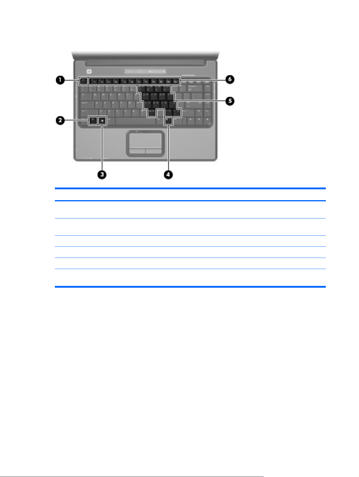
Keys
Item Component Function
(1)
(2)
(3)
(4)
(5)
(6)
esc key Displays system information when pressed in combination
with the fn key.
fn key Executes frequently used system functions when pressed in
combination with a function key or the esc key.
Windows logo key Displays the Windows Start menu.
Windows applications key Displays a shortcut menu for items beneath the pointer.
Embedded numeric keypad keys Can be used like the keys on an external numeric keypad.
Function keys Execute frequently used system functions when pressed in
combination with the fn key.
10 Chapter 2 External component identification
Page 19
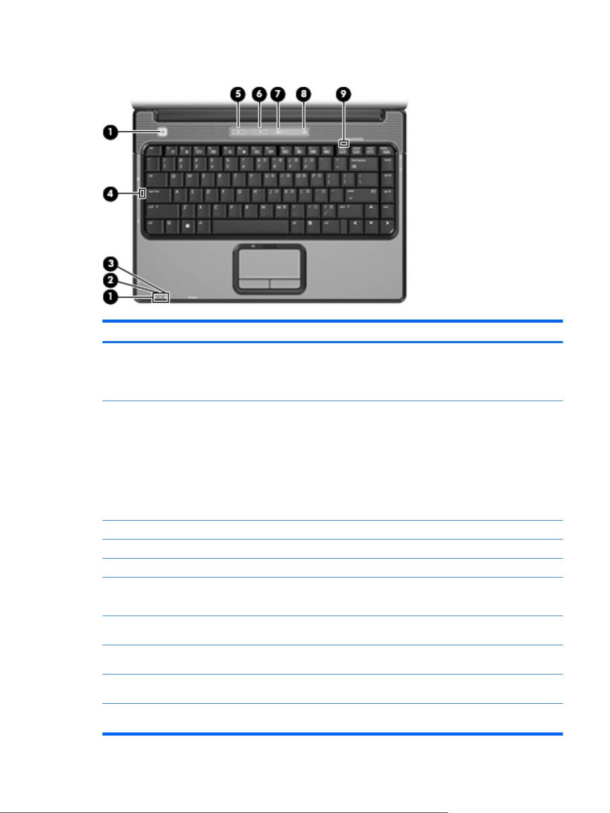
Lights
Item Component Description
(1)
(2)
(3)
(4)
(5)
(6)
(7)
Power lights (2)*
Battery light
Drive light Blinking: The hard drive or optical drive is being accessed.
Caps lock light On: Caps lock is on.
Media button light Blinks once when the media button is pressed.
Volume mute light
Volume down light Blinking: The volume scroll zone is being used to decrease
On: The computer is on.
●
Blinking: The computer is in the Sleep state.
●
Off: The computer is off or in Hibernation.
●
On: A battery is charging.
●
Blinking: A battery that is the only available power
●
source has reached a low battery level or a critical
battery level.
Off: If the computer is plugged into an external power
●
source, the light is turned off when all batteries in the
computer are fully charged. If the computer is not
plugged into an external power source, the light stays
off until the battery reaches a low battery level.
Blue: Computer sound is turned on.
●
Amber: Computer sound is turned off.
●
speaker volume.
(8)
(9)
*The 2 power lights display the same information. The light on the power button is visible only when the computer is open. The
power light on the front of the computer is visible whether the computer is open or closed.
Volume up light Blinking: The volume scroll zone is being used to increase
speaker volume.
Num lock light On: Num lock is on or the embedded numeric keypad is
enabled.
Top components 11
Page 20
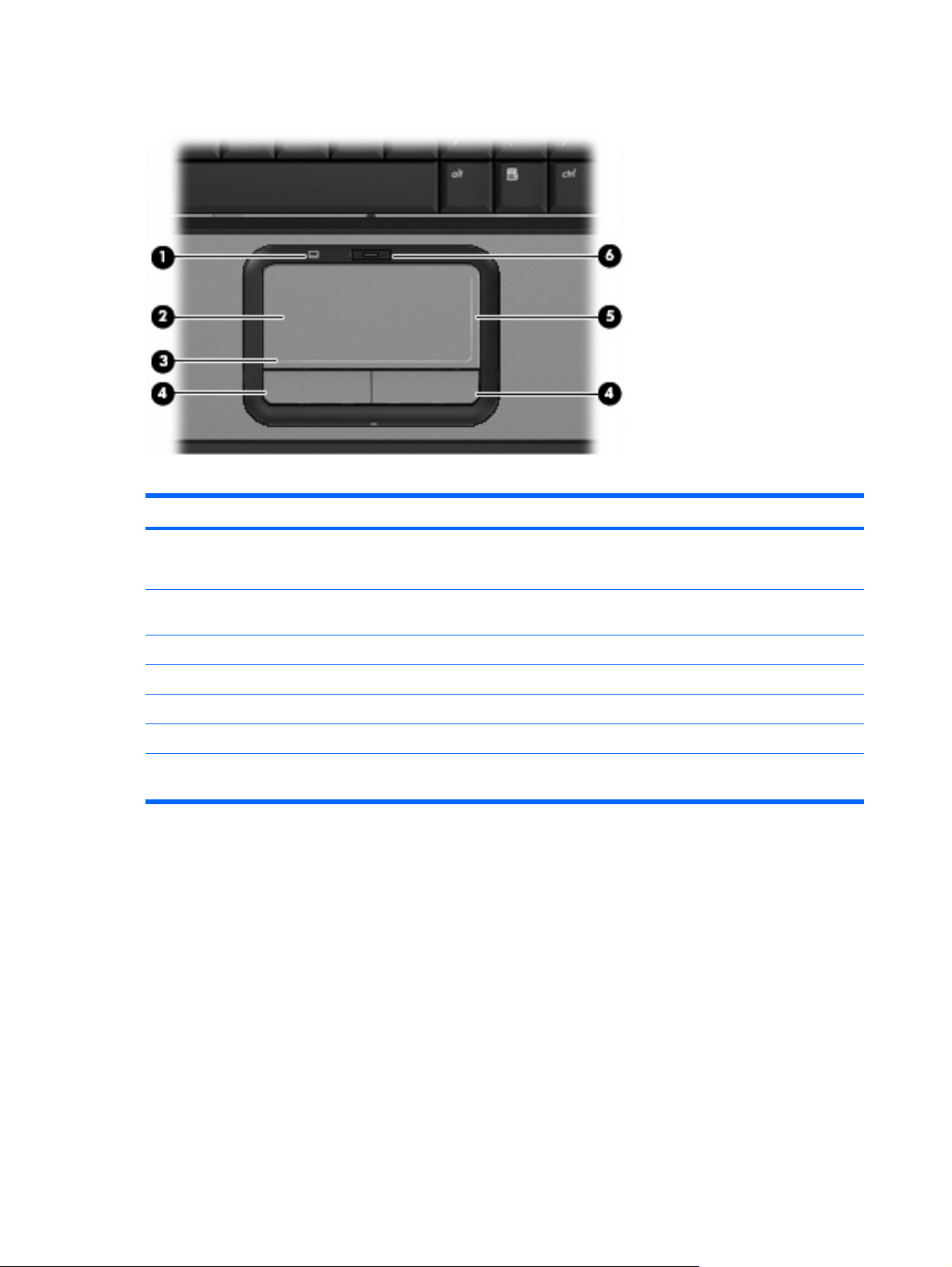
TouchPad
Item Component Function
(1)
(2)
(3)
(4)
(5)
(6)
*This table describes factory settings. To view or change pointing device preferences, select Start > Control Panel >
Hardware and Sound > Mouse.
TouchPad light
TouchPad* Moves the pointer and selects or activates items on the
TouchPad horizontal scroll zone Scrolls left or right.
Left and right TouchPad buttons* Function like the left and right buttons on an external mouse.
TouchPad vertical scroll zone Scrolls up or down.
TouchPad on/off button Enables/disables the TouchPad.
Blue: TouchPad is enabled.
●
Amber: TouchPad is disabled.
●
screen.
12 Chapter 2 External component identification
Page 21

Front components
Item Component Function
(1)
(2)
(3)
(4)
(5)
Wireless switch Turns the wireless feature on or off, but does not create a
wireless connection.
NOTE: To establish a wireless connection, a wireless
network must already be set up.
Wireless light
Consumer infrared lens (select models only) Receives a signal from a remote control device, such as an
Audio-in (microphone) Connects an optional computer headset microphone, stereo
Audio-out (headphone) jack Produces sound when connected to optional powered stereo
Blue: An integrated wireless device, such as a WLAN
●
device, and/or a Bluetooth® device, is turned on.
Amber: An integrated wireless device is turned off.
●
HP Remote Control.
array microphone, or monaural microphone.
speakers, headphones, ear buds, a headset, or television
audio.
Front components 13
Page 22

Left-side components
Item Component Function
(1)
(2)
(3)
(4)
(5)
(6)
(7)
S-Video-out jack Connects an optional S-Video device such as a television,
VCR, camcorder, overhead projector, or video capture
card.
External monitor port Connects an external VGA monitor or projector.
Expansion port 3 Connects the computer to an optional docking device or
optional expansion product.
NOTE: The computer has only one expansion port. The
term expansion port 3 describes the type of expansion port.
RJ-45 (network) jack Connects a network cable.
USB ports (1 or 2, depending on computer model) Connects optional USB devices.
1394 port (select models only) Connects an optional IEEE 1394 or 1394a device, such as
Digital Media Slot (select models only) Supports the following optional digital card formats:
a camcorder.
Memory Stick (MS)
●
Memory Stick Pro (MSP)
●
● MultiMediaCard (MMC)
Secure Digital Input/Output (SD I/O)
●
Secure Digital (SD) Memory Card
●
(8)
(9)
Digital Media Slot light (select models only) On: A digital card is being accessed.
ExpressCard slot Supports optional ExpressCard/54 cards.
14 Chapter 2 External component identification
xDPicture Card (XD)
●
xD-Picture Card (XD) Type H
●
xD-Picture Card (XD) Type M
●
Page 23

Rear component
Item Component Description
(1)
Vent Enables airflow to cool internal
components.
NOTE: The computer fan starts up
automatically to cool internal
components and prevent overheating.
It is normal for the internal fan to cycle
on and off during routine operation.
Rear component 15
Page 24
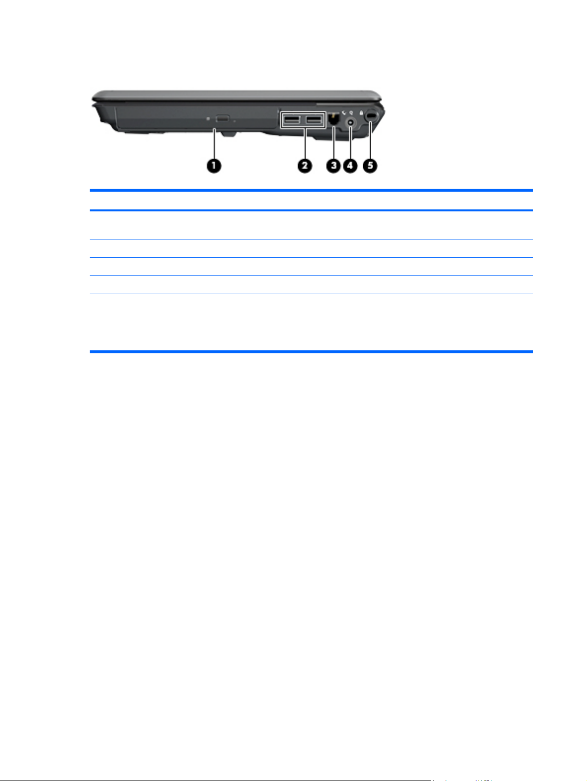
Right-side components
Item Component Function
(1)
(2)
(3)
(4)
(5)
Optical drive Reads optical discs, and, on select models, also writes to
optical discs.
USB ports (select models only) Connect optional USB devices.
RJ-11 (modem) jack Connects a modem cable.
Power connector Connects an AC adapter.
Security cable slot Attaches an optional security cable to the computer.
NOTE: The security cable is designed to act as a
deterrent, but may not prevent the computer from being
mishandled or stolen.
16 Chapter 2 External component identification
Page 25

Bottom components
Item Component Function
(1)
(2)
(3)
(4)
(5)
(6)
Battery bay Holds the battery.
Battery release latch Releases the battery from the battery bay.
Wireless module compartment Contains a WLAN module slot.
CAUTION: To prevent an unresponsive system, replace
the wireless module only with a wireless module authorized
for use in the computer by the governmental agency that
regulates wireless devices in your country or region. If you
replace the module and then receive a warning message,
remove the module to restore computer functionality, and
then contact technical support through Help and Support.
Vents (4) Enable airflow to cool internal components.
NOTE: The computer fan starts up automatically to cool
internal components and prevent overheating. It is normal
for the internal fan to cycle on and off during routine
operation.
Memory module compartment Contains 2 memory module slots.
Hard drive bay Holds the hard drive and the RTC battery.
Bottom components 17
Page 26
3
Illustrated parts catalog
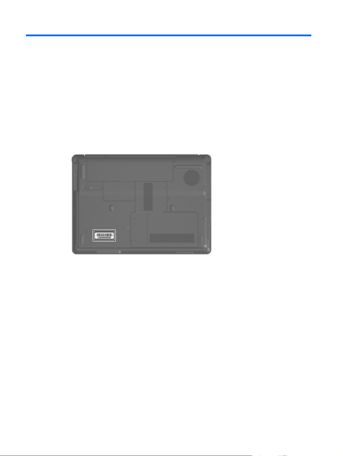
Serial number location
When ordering parts or requesting information, provide the computer serial number and model number
located on the bottom of the computer.
18 Chapter 3 Illustrated parts catalog
Page 27
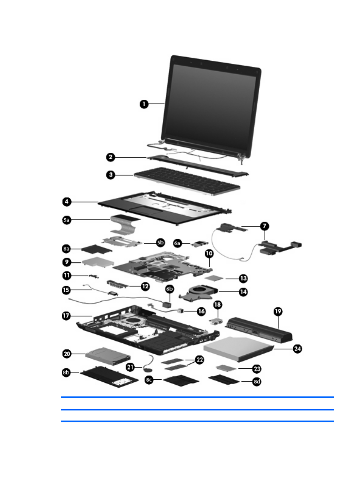
Computer major components
Item Description Spare part number
(1) 14.1-inch, WXGA, BrightView display assembly
Computer major components 19
Page 28

Item Description Spare part number
NOTE: See Display assembly components on page 27 for more display assembly internal
component spare part information.
For use in computer models with Intel or AMD processors without a camera module 448611-001
For use in defeatured computer models with AMD processors without a camera module 451163-001
For use in computer models with Intel or AMD processors with a camera module 462761-001
For use in computer models with Intel or AMD processors without a camera module; does not
include microphones
(2) Switch cover (includes power button board and cable, LED board, and LED board cable)
For use in computer models with Intel processors or full-featured models with AMD processors 451313-001
For use in defeatured computer models with AMD processors 417078-001
(3) Keyboards
Belgium 448615-021
Brazil 448615-201
Canadian French 448615-121
Denmark, Finland, Norway, and Sweden 448615-DH1
France 448615-051
Germany 448615-041
Greece 448615-DJ1
Israel 448615-BB1
Italy 448615-061
Latin America 448615-161
The Netherlands and Europe 448615-B31
457349-001
Portugal 448615-131
Russia 448615-251
Saudi Arabia 448615-171
South Korea 448615-AD1
Spain 448615-071
Switzerland 448615-111
Taiwan 448615-AB1
Thailand 448615-281
Turkey 448615-141
The United Kingdom 448615-031
The United States 448615-001
(4) Top cover (includes TouchPad and cable)
For use only in full-featured computer models with Intel processors and a camera module 462524-001
20 Chapter 3 Illustrated parts catalog
Page 29

Item Description Spare part number
For use only in full-featured computer models with Intel processors without a camera module 448620-001
For use only in full-featured computer models with AMD processors without a camera module 455857-001
For use only in defeatured computer models with AMD processors without a camera module 417091-001
For use only in defeatured computer models with Intel processors 460947-001
For use only in defeatured computer models with Intel processors and a card reader 461267-001
(5a) TouchPad
For use only in computer models with Intel processors 451341-001
For use only in computer models with AMD processors 455858-001
(5b) TouchPad bracket (included with top cover)
Modem module (includes modem module cable)
(6a)
(6b) Modem module cable
(7) Speaker assembly
Door/Cover Kit (see Door/Cover Kit on page 30 for more Door/Cover Kit information)
ExpressCard slot bezel
(8a)
Hard drive cover
(8b)
Memory module compartment cover
(8c)
Wireless module compartment cover
(8d)
ExpressCard assembly
(9)
(10) System boards (include thermal material)
For use only in computer models with Intel processors:
Equipped with discrete graphics subsystems and without a camera module
●
463971-001
455847-001
417089-001
417112-001
448596-001
For use only in computer models with AMD processors:
● Defeatured computer models without a camera module 453412-001
(11) Wireless switch board (includes wireless switch board cable)
(12) Audio board (includes audio connectors, infrared lens, and audio board cable)
For use only in full-featured computer models without a camera module 459157-001
For use only in defeatured computer models with AMD processors without a camera module 448627-001
Not equipped with UMA graphics subsystems and without a camera module
●
Equipped with discrete graphics subsystems and with a camera module
●
Not equipped with UMA graphics subsystems and with a camera module
●
On defeatured models
●
Full-featured computer models without a camera module
●
Full-featured computer models with a camera module
●
Defeatured computer models with a camera module
●
448598-001
460716-001
460715-001
460717-001
453411-001
462535-001
462536-001
417092-001
Computer major components 21
Page 30

Item Description Spare part number
For use only in full-featured computer models with a camera module 463974-001
For use only in defeatured computer models with AMD processors with a camera module 463975-001
(13) Processors (include thermal material)
Intel Core 2 Duo processors:
● T7100 (1.8-GHz, 2-MB L2 cache) 448600-001
● T5450 (1.67-GHz, 2-MB L2 cache) 451597-001
Intel Pentium Dual-Core processors:
T9300 (2.50-GHz, 6-MB L2 cache)
●
T8300 (2.40-GHz, 3-MB L2 cache)
●
T8100 (2.10-GHz, 3-MB L2 cache)
●
T7700 (2.40-GHz, 4-MB L2 cache)
●
T7500 (2.20-GHz, 4-MB L2 cache)
●
T7300 (2.00-GHz, 4-MB L2 cache)
●
T7250 (2.00-GHz, 2-MB L2 cache)
●
T5750 (2.00-GHz, 2-MB L2 cache)
●
T5550 (1.83-GHz, 2-MB L2 cache)
●
T5250 (1.50-GHz, 2-MB L2 cache)
●
T2370 (1.73 GHz, 1-MB L2 cache)
●
T2330 (1.60 GHz, 1-MB L2 cache)
●
T2310 (1.46-GHz, 1-MB L2 cache)
●
459799-001
459798-001
459797-001
448148-001
457312-001
448601-001
457311-001
462353-001
458247-001
453948-001
462354-001
457314-001
457313-001
Intel Celeron M processors:
AMD processors:
● Turion TL-60 (2.0-GHz, 1-MB L2 cache) 455807-001
● Turion MK-38 (2.2-GHz, 512-MB L2 cache) 449904-001
540 (1.86-GHz, 1-MB L2 cache)
●
530 (1.73-GHz, 1-MB L2 cache)
●
Turion TL-68 (2.4-GHz, 1-MB L2 cache)
●
Turion TL-66 (2.3-GHz, 1-MB L2 cache)
●
Turion TL-62 (2.1-GHz, 1-MB L2 cache)
●
Turion TL-58 (1.9-GHz, 1-MB L2 cache)
●
Turion TL-55 (1.86-GHz, 1-MB L2 cache)
●
Athlon TK-53 (1.9-GHz, 2-GB L2 cache)
●
Athlon TK-53 (1.7-GHz, 2-GB L2 cache)
●
Sempron 3800 (2.2-GHz, 256-KB L2 cache) 459760-001
●
450995-001
457315-001
463917-001
450804-001 and
453298-001
455809-001
448561-001
455808-001
459759-001
451013-001
22 Chapter 3 Illustrated parts catalog
Page 31

Item Description Spare part number
● Sempron 3600 (2.0-GHz, 256-KB L2 cache) 450609-001
(14) Fan/heat sink assembly (includes thermal material)
For use in computer models with AMD processors 455843-001
For use in computer models with Intel processors 450096-001
Fan/heat sink mounting bracket (not illustrated)
(15) Bluetooth module (includes Bluetooth module cable)
Bluetooth module cable for use only in computer models with AMD processors (not
illustrated)
(16) Power connector cable
For use in computer models with Intel processors 448629-001
For use in computer models with AMD processors 430462-001
(17) Base enclosure (includes infrared lens and wireless on/off switch)
For use only in computer models with Intel processors without a camera module 417094-001
For use only in defeatured computer models with Intel processors with a camera module 461268-001
For use only in computer models with AMD processors without a camera module 455850-001
For use only in defeatured computer models with Intel or AMD processors without a camera
module
Rubber Feet Kit (not illustrated; includes base enclosure rubber feet and display bezel
screw covers)
417114-001
397923-002
458663-001
430470-001
417096-001
(18) USB board (includes USB board cable)
For use only in computer models with Intel processors 417085-001
For use only in computer models with AMD processors 455859-001
(19) Batteries
For use in computer models with Intel or AMD processors:
● 6-cell, 2.55-Ah, Li-ion 441611-001
For use only in computer models with Intel processors:
● 12-cell, 2.20-Ah, Li-ion 452056-001
● 6-cell, 2.20-Ah, Li-ion 452057-001
(20) Hard drives (include hard drive bracket)
For use only in computer models with Intel processors:
320-GB, 5400-rpm
●
250-GB, 5400-rpm
●
200-GB, 4200-rpm
●
160-GB, 5400-rpm
●
120-GB, 5400-rpm 452059-001
●
459611-003
453949-001
455740-001
452060-001
Computer major components 23
Page 32

Item Description Spare part number
● 80-GB, 5400-rpm 452058-001
For use in computer models with AMD processors:
● 320-GB, 5400-rpm 459611-002
● 250-GB, 5400-rpm 455827-001
● 120-GB, 5400-rpm 453417-001
(21) RTC battery (includes 2-sided tape)
(22) Memory modules (667-MHz, PC2-5300, 1-DIMM)
● 2048-MB 455739-001
For use in computer models with AMD processors:
(23) WLAN modules
802.11a/b/g/n WLAN modules:
160-GB, 5400-rpm
●
80-GB, 5400-rpm
●
Hard drive hardware kit (contains screws, hard drive bracket, and connector; not
illustrated)
For use in computer models with Intel processors:
1024-MB
●
512-MB
●
2048-MB
●
1024-MB
●
512-MB
●
453418-001
453416-001
453419-001
417076-001
452062-001
452061-001
448151-002
453415-001
453414-001
● For use in Antigua and Barbuda, Argentina, Aruba, the Bahamas, Barbados, Bermuda,
802.11a/b/g WLAN modules:
Brunei, Canada, the Cayman Islands, Chile, Colombia, Costa Rica, the Dominican
Republic, Ecuador, El Salvador, Guam, Guatemala, Haiti, Honduras, Hong Kong, India,
Indonesia, Malaysia, Mexico, Panama, Paraguay, Peru, Saudi Arabia, Taiwan,
Uruguay, the United States, Venezuela, and Vietnam
For use in Austria, Azerbaijan, Bahrain, Belgium, Brazil, Bulgaria, Croatia, Cyprus, the
●
Czech Republic, Denmark, Egypt, Estonia, Finland, France, Georgia, Germany, Greece,
Hungary, Iceland, Ireland, Israel, Italy, Latvia, Lebanon, Liechtenstein, Lithuania,
Luxembourg, Malta, Monaco, the Netherlands, Norway, Oman, the Philippines, Poland,
Portugal, Qatar, Romania, Russia, Serbia and Montenegro, Singapore, Slovakia,
Slovenia, South Africa, Spain, Sri Lanka, Sweden, Switzerland, Turkey, Ukraine, the
United Kingdom, and Uzbekistan
For use in Australia, New Zealand, Pakistan, the People's Republic of China, and South
●
Korea
For use in Japan
●
For use in South Korea
●
For use in Antigua and Barbuda, Argentina, Australia, the Bahamas, Barbados, Brunei,
●
Canada, Chile, the Dominican Republic, Guam, Guatemala, Hong Kong, India,
24 Chapter 3 Illustrated parts catalog
441086-001
441086-002
441086-003
441086-291
441086-AD1
452063-001
Page 33

Item Description Spare part number
Indonesia, Malaysia, Mexico, New Zealand, Panama, Paraguay, Saudi Arabia,
Taiwan, the United States, and Vietnam
802.11b/g WLAN module for use in Thailand 409407-004
Broadcom 4311AG 802.11a/b/g modules:
For use in Aruba, Austria, Azerbaijan, Bahrain, Belgium, Bermuda, Brazil, Bulgaria, the
●
Cayman Islands, Colombia, Croatia, Cyprus, the Czech Republic, Denmark, Egypt, El
Salvador, Estonia, Finland, France, Georgia, Germany, Greece, Hungary, Iceland,
Ireland, Italy, Jordan, Latvia, Lebanon, Liechtenstein, Lithuania, Luxembourg, Malta,
Monaco, the Netherlands, Norway, Oman, the Philippines, Poland, Portugal, Romania,
Russia, Serbia and Montenegro, Singapore, Slovakia, Slovenia, South Africa, Spain,
Sri Lanka, Sweden, Switzerland, Turkey, the United Kingdom, and Uzbekistan
For use in Ecuador, Haiti, Honduras, Pakistan, the People's Republic of China, Peru,
●
Qatar, South Korea, Uruguay, and Venezuela
For use in the United States and Canada
●
For use in Afghanistan, Albania, Algeria, Andorra, Angola, Antigua & Barbuda,
●
Argentina, Armenia, Aruba, Australia, Austria, Azerbaijan, the Bahamas, Bahrain,
Bangladesh, Barbados, Belarus, Belgium, Belize, Benin, Bermuda, Bhutan, Bolivia,
Bosnia & Herzegovina Botswana, Brazil, the British Virgin Islands, Brunei, Bulgaria,
Burkina Faso, Burundi, Cambodia, Cameroon, Cape Verde, the Central African
Republic, Chad, Chile, Colombia, Comoros, the Congo, Costa Rica, Croatia, Cyprus,
the Czech Republic, Denmark, Djibouti, Dominica, the Dominican Republic, East Timor,
Ecuador, Egypt, El Salvador, Equitorial Guinea, Eritrea, Estonia, Ethiopia, Fiji, Finland,
France, French Guiana, Gabon, Gambia, Georgia, Germany, Ghana, Gibraltar,
Greece, Grenada, Guadeloupe, Guatemala, Guinea, Guinea-Bissau, Guyana, Haiti,
Honduras, Hong Kong, Hungary, Iceland, India, Indonesia, Ireland, Israel, Italy, the
Ivory Coast, Jamaica, Jordan, Kazakhstan, Kenya, Kiribati, Kuwait, Kyrgyzstan, Laos,
Latvia, Lebanon, Lesotho, Liberia, Liechtenstein, Lithuania, Luxembourg, Macedonia,
Madagascar, Malawi, Malaysia, the Maldives, Mali, Malta, the Marshall Islands,
Martinique, Mauritania, Mauritius, Mexico, Micronesia, Monaco, Mongolia,
Montenegro, Morocco, Mozambique, Namibia, Nauru, Nepal, the Nether Antilles, the
Netherlands, New Zealand, Nicaragua, Niger, Nigeria, Norway, Oman, Palau,
Panama, Papua New Guinea, Paraguay, the People's Republic of China, Peru, the
Philippines, Poland, Portugal, Qatar, the Republic of Moldova, Romania, Russia,
Rwanda, Samoa, San Marino, Sao Tome & Principe, Saudi Arabia, Senegal, Serbia
and Montenegro, the Seychelles, Sierra Leone, Singapore, Slovakia, Slovenia, the
Solomon Islands, Somalia, South Africa, South Korea, Spain, Sri Lanka, St. Kitts & Nevis,
St. Lucia, St. Vincent & the Grenadines, Suriname, Swaziland, Sweden, Switzerland,
Taiwan, Tajikistan, Tanzania, Thailand, Togo, Tonga, Trinidad & Tobago, Tunisia,
Turkey, Turkmenistan, Tuvalu, Uganda, Ukraine, the United Arab Emirates, the United
Kingdom, Uruguay, Uzbekistan, Vanuatu, Venezuela, Vietnam, Yemen, Zaire, Zambia,
and Zimbabwe
452063-002
452063-001
441075-001
441075-002
● For use in Japan 441075-291
Broadcom 802.11b/g WLAN modules:
● For use in Canada, the Cayman Islands, Guam, Puerto Rico, the U.S. Virgin Islands, and
the United States
For use in Afghanistan, Albania, Algeria, Andorra, Angola, Antigua & Barbuda,
●
Argentina, Armenia, Aruba, Australia, Austria, Azerbaijan, the Bahamas, Bahrain,
Bangladesh, Barbados, Belarus, Belgium, Belize, Benin, Bermuda, Bhutan, Bolivia,
Bosnia & Herzegovina Botswana, Brazil, the British Virgin Islands, Brunei, Bulgaria,
Burkina Faso, Burundi, Cambodia, Cameroon, Cape Verde, the Central African
Republic, Chad, Chile, Colombia, Comoros, the Congo, Costa Rica, Croatia, Cyprus,
the Czech Republic, Denmark, Djibouti, Dominica, the Dominican Republic, East Timor,
Ecuador, Egypt, El Salvador, Equitorial Guinea, Eritrea, Estonia, Ethiopia, Fiji, Finland,
France, French Guiana, Gabon, Gambia, Georgia, Germany, Ghana, Gibraltar,
441090-001
441090-002
Computer major components 25
Page 34

Item Description Spare part number
Greece, Grenada, Guadeloupe, Guatemala, Guinea, Guinea-Bissau, Guyana, Haiti,
Honduras, Hong Kong, Hungary, Iceland, India, Indonesia, Ireland, Israel, Italy, the
Ivory Coast, Jamaica, Jordan, Kazakhstan, Kenya, Kiribati, Kuwait, Kyrgyzstan, Laos,
Latvia, Lebanon, Lesotho, Liberia, Liechtenstein, Lithuania, Luxembourg, Macedonia,
Madagascar, Malawi, Malaysia, the Maldives, Mali, Malta, the Marshall Islands,
Martinique, Mauritania, Mauritius, Mexico, Micronesia, Monaco, Mongolia,
Montenegro, Morocco, Mozambique, Namibia, Nauru, Nepal, the Nether Antilles, the
Netherlands, New Zealand, Nicaragua, Niger, Nigeria, Norway, Oman, Palau,
Panama, Papua New Guinea, Paraguay, the People's Republic of China, Peru, the
Philippines, Poland, Portugal, Qatar, the Republic of Moldova, Romania, Russia,
Rwanda, Samoa, San Marino, Sao Tome & Principe, Saudi Arabia, Senegal, Serbia
and Montenegro, the Seychelles, Sierra Leone, Singapore, Slovakia, Slovenia, the
Solomon Islands, Somalia, South Africa, South Korea, Spain, Sri Lanka, St. Kitts & Nevis,
St. Lucia, St. Vincent & Grenadines, Suriname, Swaziland, Sweden, Switzerland,
Taiwan, Tajikistan, Tanzania, Thailand, Togo, Tonga, Trinidad & Tobago, Tunisia,
Turkey, Turkmenistan, Tuvalu, Uganda, Ukraine, the United Arab Emirates, the United
Kingdom, Uruguay, Uzbekistan, Vanuatu, Venezuela, Vietnam, Yemen, Zaire, Zambia,
and Zimbabwe
802.11n WLAN modules:
Broadcom BCM4312 WLAN b/g modules:
For use in Japan
●
For use in the United States and Canada
●
For use in the Argentina, Australia, Belize, Bolivia, Brazil, Chile, Columbia, Costa Rica,
●
Ecuador, El Salvador, Guatemala, Honduras, Hong Kong, Indonesia, Nicaragua,
Paraguay, the People's Republic of China, Peru, South Korea, Taiwan, Thailand,
Uruguay, Venezuela
For use in Japan
●
For use in Canada, Cayman Islands, Guam, Puerto Rico, the United States, and the
●
Virgin Islands
For use in Afghanistan, Albania, Algeria, Andorra, Angola, Antigua & Barbuda,
●
Argentina, Armenia, Australia, Austria, Azerbaijan, Bahamas, Bahrain, Bangladesh,
Barbados, Belarus, Belgium, Belize, Benin, Bhutan, Bolivia, Bosnia & Herzegovina,
Botswana, Brazil, Brunei, Bulgaria, Burkina, Faso Burundi, Cambodia, Cameroon,
Cape Verde, Central African Republic, Chad, Zaire, Chile, China, Colombia, Comoros,
Congo, Costa Rica, Croatia, Cyprus, Czech Republic, Denmark, Djibouti, Dominica,
Dominican Republic, Ecuador, Egypt, El Salvador, Equitorial Guinea, Eritrea, Estonia,
Ethiopia, Fiji, Finland, France, Gabon, Gambia, Georgia, Germany, Ghana, Gibraltar,
Greece, Grenada, Guatemala, Guinea, Guinea-Bissau, Guyana, Haiti, Honduras,
Hong Kong, Hungary, Iceland, India, Indonesia, Ireland, Israel, Italy, Ivory Coast,
Jamaica, Japan, Jordan, Kazakhstan, Kenya, Kiribati, Kuwait, Kyrgyzstan, Laos, Latvia,
Lebanon, Lesotho, Liberia, Martinique, British Virgin Islands, French Guiana,
Guadeloupe, Nether Antilles, Aruba, Bermuda, Syria, Liechtenstein, Lithuania,
Luxembourg, Macedonia, Madagascar, Malawi, Malaysia, Maldives, Mali, Malta,
Marshall Islands, Mauritania, Mauritius, Mexico, Micronesia, Monaco, Mongolia,
Montenegro, Morocco, Mozambique, Namibia, Nauru, Nepal, Netherlands, New
Zealand, Nicaragua, Niger, Nigeria, Norway, Oman, Pakistan, Palau, Panama, Papua
New Guinea, Paraguay, Peru, Philippines, Poland, Portugal, Qatar, Republic of
Moldova, Romania, Russia, Rwanda, Samoa, San Marino, Sao Tome & Principe, Saudi
Arabia, Senegal, Serbia and Montenegro, Seychelles, Sierra Leone, Singapore,
Slovakia, Slovenia, Solomon Islands, Somalia, South Africa, South Korea, Spain, Sri
Lanka, St. Kitts & Nevis, St. Lucia, St. Vincent & Grenadines, Suriname, Swaziland,
Sweden, Switzerland, Taiwan, Tajikistan, Tanzania, Thailand, East Timor, Togo, Tonga,
Trinidad & Tobago, Tunisia, Turkey, Turkmenistan, Tuvalu, Uganda, Ukraine, United
Arab Emirates, United Kingdom, Uruguay, Uzbekistan, Vanuatu, Venezuela, Vietnam,
Yemen, Zambia, and Zimbabwe
441090-291
436255-001
436256-001
436256-291
459263-001
459263-002
26 Chapter 3 Illustrated parts catalog
Page 35

Item Description Spare part number
(24) Optical drives (include bezel)
For use in computer models with Intel processors:
For use in computer models with AMD processors:
DVD±RW and CD-RW Super Multi, Double-Layer Combo Drive with LightScribe
●
DVD±RW and CD-RW Super Multi, Double-Layer Combo Drive
●
DVD/CD-RW Combo Drive
●
DVD±RW and CD-RW Super Multi Double-Layer Combo Drive with LightScribe
●
DVD±RW and CD-RW Super Multi Double-Layer Combo Drive
●
DVD/CD-RW Combo Drive
●
Cable Kit (not illustrated; see
Cable Kit on page 31 for more Cable Kit information)
Display assembly components
452055-001
452054-001
452053-001
455830-002
455829-002
455828-002
430474-001
Item Description Spare part number
(1) Display bezels
For use with full-featured computer models with Intel processors 462525-001
For use with defeatured computer models with Intel processors 457351-001
Display assembly components 27
Page 36

Item Description Spare part number
For use with computer models with Intel or AMD processors without a camera module;
includes microphone
For use only with computer models with AMD processors without a camera module; does not
include microphone
For use with computer models with AMD processors with a camera module; includes
microphone
(2a) Display inverter (includes Mylar shield)
For use only with computer models with Intel processors 417097-001
For use only with computer models with AMD processors 455821-001
(2b) Display inverter bracket (included with display inverter)
Camera module (includes camera module bracket and 2-sided tape)
(3)
(4) Wireless Antenna Kit
Antenna, microphone cable kit (not illustrated)
(5) 14.1-inch, WXGA, TFT BrightView display panel (includes display panel cable)
For use only with computer models with Intel processors 448602-001
For use only with computer models with AMD processors 455810-001
Display Hinge Kit
For use only with computer models with Intel processors 417103-001
448613-001
455820-001
461913-001
453673-001
417107-001
458658-001
For use only with computer models with AMD processors 455822-001
(6a) Left and right display hinges
Display switch module
(6b)
(7) Display Cable Kit (includes microphones and cables)
For use only with computer models with Intel processors with a camera module 462562-001
For use only with computer models with Intel processors without a camera module 448614-001
For use only with computer models with AMD processors 458656-001
(8) Display enclosure
For use only with computer models with Intel processors with a camera module 457350-001
For use only with computer models with Intel processors without a camera module 448612-001
For use only with computer models with AMD processors without a camera module 455818-001
For use only with computer models with AMD processors with a camera module 461914-001
(9) Camera module cable
For models only with Intel processors and a camera module
For models only with AMD processors and a camera module
Display Screw Kit (not illustrated; includes screws and rubber screw covers)
431881-001
462526-001
461915-001
For use only with computer models with Intel processors 417105-001
28 Chapter 3 Illustrated parts catalog
Page 37

Item Description Spare part number
For use only with computer models with AMD processors 455868-001
Rubber display kit (not illustrated)
Display bracket (not illustrated)
458654-001
455812-001
Display assembly components 29
Page 38

Door/Cover Kit
Item Description Spare part number
Door/Cover Kit
Wireless module compartment cover (includes 1 captive screw, secured by a C-clip)
(1)
Hard drive cover (includes 2 captive screws, secured by C-clips)
(2)
Memory module compartment cover (includes 2 captive screws, secured by C-clips)
(3)
ExpressCard slot bezel
(4)
417074-001
30 Chapter 3 Illustrated parts catalog
Page 39

Cable Kit
Item Description Spare part number
Cable Kit
Power button board cable
(1)
LED board cable
(2)
USB/power connector board cable (includes num lock light)
(3)
Bluetooth module cable
(4)
Modem module cable (includes RJ-11 connector)
(5)
430474-001
Cable Kit 31
Page 40

Mass storage devices
Item Description Spare part number
(1) Hard drives (include hard drive bracket)
For use only in computer models with Intel processors:
For use in computer models with AMD processors:
● 120-GB, 5400-rpm 453417-001
● 80-GB, 5400-rpm 453416-001
(2) Optical drives (include bezel and bracket)
320-GB, 5400-rpm
●
250-GB, 5400-rpm
●
200-GB, 4200-rpm
●
160-GB, 5400-rpm
●
120-GB, 5400-rpm
●
80-GB, 5400-rpm
●
320-GB, 5400-rpm
●
250-GB, 5400-rpm
●
160-GB, 5400-rpm
●
Hard drive hardware kit (contains screws, hard drive bracket, and connector; not
illustrated)
For use only in computer models with Intel processors:
DVD±RW and CD-RW Super Multi, Double-Layer Combo Drive with LightScribe
●
459611-003
453949-001
455740-001
452060-001
452059-001
452058-001
459611-002
455827-001
453418-001
453419-001
452055-001
For use in computer models with AMD processors:
DVD±RW and CD-RW Super Multi, Double-Layer Combo Drive
●
DVD/CD-RW Combo Drive
●
32 Chapter 3 Illustrated parts catalog
452054-001
452053-001
Page 41

Item Description Spare part number
● DVD±RW and CD-RW Super Multi Double-Layer Combo Drive with LightScribe 455830-002
● DVD/CD-RW Combo Drive 455828-002
DVD±RW and CD-RW Super Multi Double-Layer Combo Drive
●
455829-002
Mass storage devices 33
Page 42

Miscellaneous parts
Description Spare part number
AC adapters
90-W PFC AC adapter
65-W PFC AC adapter 417220-001
ATSC/NTSC/PAL TV tuner
ATSC/NTSC TV tuner antenna
Composite audio and S-Video cable
DVB-T tuner
DVB-T tuner
DVB-T antenna adapter; for use with 412175-001
DVB-T antenna adapter; for use with 412175-002
Earbud headset
HP backpack
HP carrying case
HP slipcase
HP Remote Control for use with computer models with Intel processors
HP Remote Control for use with computer models with AMD processors
Infrared emitter with cable
409515-001
439130-001
439131-001
407939-001
412175-001
412175-002
412176-001
412176-003
371693-003
405527-001
418162-001
458248-001
407313-001
435743-001
439129-001
Optical wired mouse
RF input adapter cable (without ferrite)
USB digital drive
Windows Vista remote control (fits inside ExpressCard slot)
Windows Vista remote control (does not fit inside ExpressCard slot)
Wireless laser mouse (includes cable adapter)
Fingerprint reader
Power cords:
Argentina
Australia and New Zealand 383496-011
Belgium, Europe, Finland, France, Germany, Greece, the Netherlands, Norway, Portugal, Spain, and
Sweden
Brazil 383496-201
Canada, French Canada, Latin America, Thailand, and the United States 383496-001
Denmark 383496-081
India 383496-D61
436238-001
407940-001
364727-002
439128-001
439254-001
430958-001
458113-001
383496-D01
383496-021
34 Chapter 3 Illustrated parts catalog
Page 43

Description Spare part number
Israel 383496-BB1
Italy 383496-061
Japan 383496-291
The People's Republic of China 383496-AA1
South Africa 383496-AR1
South Korea 383496-AD1
Switzerland 383496-111
Taiwan 383496-AB1
The United Kingdom and Hong Kong 383496-031
Screw Kit
For use in computers with Intel processors 417109-001
For use in computers with AMD processors 455867-001
Phillips PM3.0×4.0 screw
●
Phillips PM2.5×9.0 screw
●
Phillips PM2.5×7.0 screw
●
Phillips PM2.5×5.0 screw
●
Phillips PM2.5×4.0 screw
●
Phillips PM2.0×13.0 captive screw
●
Phillips PM2.0×9.0 captive screw
●
Phillips PM2.0×8.0 screw
●
Phillips PM2.0×5.0 screw
●
Phillips PM2.0×5.0 captive screw
●
Phillips PM2.0×4.0 screw
●
Phillips PM2.0×3.0 screw
●
Phillips PM2.0×2.0 screw
●
Sequential part number listing
Spare part
number
364727-002 USB digital drive
371693-003 USB digital drive
383496-001 Power cord for use in the United States
383496-011 Power cord for use in Australia
Description
Sequential part number listing 35
Page 44

Spare part
number
383496-021 Power cord for use in Europe
383496-031 Power cord for use in the United Kingdom
383496-061 Power cord for use in Italy
383496-081 Power cord for use in Denmark
383496-111 Power cord for use in Switzerland
383496-201 Power cord for use in Brazil
383496-291 Power cord for use in Japan
383496-AA1 Power cord for use in the People's Republic of China
383496-AB1 Power cord for use in Taiwan
383496-AD1 Power cord for use in South Korea
383496-AR1 Power cord for use in South Africa
383496-BB1 Power cord for use in Israel
383496-D01 Power cord for use in Argentina
383496-D61 Power cord for use in India
397923-002 Bluetooth module (includes Bluetooth module cable)
Description
405527-001 HP backpack
407313-001 HP Remote Control for use with computers with Intel processors
407939-001 Composite video cable
407940-001 RF input adapter cable (without ferrite)
408479-002 TV tuner remote control for use in Europe, the Middle East, and Africa
408483-001 USB infrared receiver
409407-004 802.11b/g WLAN module for use in Thailand
409515-001 90-W PFC AC adapter
412175-001 DVB-T tuner
412175-002 DVB-T tuner
412176-001 DVB-T antenna adapter; for use with 412175-001
412176-002 DVB-T antenna and DVB-T antenna adapter
412176-003 DVB TV antenna adapter; for use with 412175-002
417074-001 Door/Cover Kit (see Door/Cover Kit on page 30) for more Door/Cover Kit information)
417076-001 RTC battery (includes 2-sided tape)
417078-001 Switch cover for use in defeatured computer models with AMD processors (includes power button board and
cable, LED board, and LED board cable)
417085-001 USB board for use only in computer models with Intel processors (includes USB board cable)
417089-001 Speaker assembly
36 Chapter 3 Illustrated parts catalog
Page 45

Spare part
number
417091-001 Top cover for use in defeatured computer models with AMD processors (includes TouchPad and cable)
417092-001 Wireless switch board (includes wireless switch board cable)
417094-001 Base enclosure for use only in computer models with Intel processors without a camera module (includes infrared
417096-001 Rubber Feet Kit (includes base enclosure rubber feet and display bezel screw covers)
417097-001 Display inverter for use only in computer models with Intel processors (includes Mylar shield and bracket)
Description
lens and wireless on/off switch)
417103-001 Display Hinge Kit for use in computer models with Intel processors (includes left and right display hinges and
417105-001 Display Screw Kit for use only in computer models with Intel processors (includes screws and rubber screw
417107-001 Wireless Antenna Kit
417109-001 Screw Kit for use in computer models with Intel processors
417112-001 ExpressCard assembly
417114-001 Fan/heat sink mounting bracket
417220-001 65-W PFC AC adapter
418162-001 HP carrying case
430462-001 Power connector cable for use in computer models with AMD processors
430470-001 Base enclosure for use only in defeatured computer models with Intel or AMD processors without a camera
430474-001 Cable Kit (see Cable Kit on page 31 for more Cable Kit information)
430958-001 Wireless laser mouse (includes cable adapter)
431881-001 Display switch module
435743-001 HP Remote Control for use with computers with AMD processors
436238-001 Optical wired mouse
display switch module)
covers)
module (includes infrared lens and wireless on/off switch)
436255-001 WLAN 802.11n module for use in the United States and Canada
436256-001 WLAN 802.11n module for use in the Argentina, Australia, Belize, Bolivia, Brazil, Chile, Columbia, Costa Rica,
Ecuador, El Salvador, Guatemala, Honduras, Hong Kong, Indonesia, Nicaragua, Paraguay, the People's
Republic of China, Peru, South Korea, Taiwan, Thailand, Uruguay, Venezuela
439128-001 Windows Vista remote control (fits inside ExpressCard slot)
439129-001 Infrared emitter with cable
439130-001 ATSC/NTSC/PAL TV tuner
439131-001 ATSC/NTSC TV tuner antenna
439254-001 Windows Vista remote control (does not fit inside ExpressCard slot)
441075-001 Broadcom 4311AG 802.11a/b/g WLAN module for use in the United States and Canada
441075-002 Broadcom 4311AG 802.11a/b/g WLAN module for use in Afghanistan, Albania, Algeria, Andorra, Angola,
Antigua & Barbuda, Argentina, Armenia, Aruba, Australia, Austria, Azerbaijan, the Bahamas, Bahrain,
Bangladesh, Barbados, Belarus, Belgium, Belize, Benin, Bermuda, Bhutan, Bolivia, Bosnia & Herzegovina
Botswana, Brazil, the British Virgin Islands, Brunei, Bulgaria, Burkina Faso, Burundi, Cambodia, Cameroon,
Sequential part number listing 37
Page 46

Spare part
number
441086-001 802.11a/b/g/n WLAN module for use in Antigua and Barbuda, Argentina, Aruba, the Bahamas, Barbados,
Description
Cape Verde, the Central African Republic, Chad, Chile, Colombia, Comoros, the Congo, Costa Rica, Croatia,
Cyprus, the Czech Republic, Denmark, Djibouti, Dominica, the Dominican Republic, East Timor, Ecuador, Egypt,
El Salvador, Equitorial Guinea, Eritrea, Estonia, Ethiopia, Fiji, Finland, France, French Guiana, Gabon, Gambia,
Georgia, Germany, Ghana, Gibraltar, Greece, Grenada, Guadeloupe, Guatemala, Guinea, Guinea-Bissau,
Guyana, Haiti, Honduras, Hong Kong, Hungary, Iceland, India, Indonesia, Ireland, Israel, Italy, the Ivory Coast,
Jamaica, Jordan, Kazakhstan, Kenya, Kiribati, Kuwait, Kyrgyzstan, Laos, Latvia, Lebanon, Lesotho, Liberia,
Liechtenstein, Lithuania, Luxembourg, Macedonia, Madagascar, Malawi, Malaysia, the Maldives, Mali, Malta,
the Marshall Islands, Martinique, Mauritania, Mauritius, Mexico, Micronesia, Monaco, Mongolia, Montenegro,
Morocco, Mozambique, Namibia, Nauru, Nepal, the Nether Antilles, the Netherlands, New Zealand,
Nicaragua, Niger, Nigeria, Norway, Oman, Palau, Panama, Papua New Guinea, Paraguay, the People's
Republic of China, Peru, the Philippines, Poland, Portugal, Qatar, the Republic of Moldova, Romania, Russia,
Rwanda, Samoa, San Marino, Sao Tome & Principe, Saudi Arabia, Senegal, Serbia and Montenegro, the
Seychelles, Sierra Leone, Singapore, Slovakia, Slovenia, the Solomon Islands, Somalia, South Africa, South
Korea, Spain, Sri Lanka, St. Kitts & Nevis, St. Lucia, St. Vincent & Grenadines, Suriname, Swaziland, Sweden,
Switzerland, Taiwan, Tajikistan, Tanzania, Thailand, Togo, Tonga, Trinidad & Tobago, Tunisia, Turkey,
Turkmenistan, Tuvalu, Uganda, Ukraine, the United Arab Emirates, the United Kingdom, Uruguay, Uzbekistan,
Vanuatu, Venezuela, Vietnam, Yemen, Zaire, Zambia, and Zimbabwe
Bermuda, Brunei, Canada, the Cayman Islands, Chile, Colombia, Costa Rica, the Dominican Republic, Ecuador,
El Salvador, Guam, Guatemala, Haiti, Honduras, Hong Kong, India, Indonesia, Malaysia, Mexico, Panama,
Paraguay, Peru, Saudi Arabia, Taiwan, Uruguay, the United States, Venezuela, and Vietnam
441086-002 802.11a/b/g/n WLAN module for use in Austria, Azerbaijan, Bahrain, Belgium, Brazil, Bulgaria, Croatia,
441086-003 802.11a/b/g/n WLAN module for use in Australia, New Zealand, Pakistan, the People's Republic of China,
441086-291 802.11a/b/g/n WLAN module for use in Japan
441086-AD1 802.11a/b/g/n WLAN module for use in South Korea
441090-001 Broadcom 802.11b/g WLAN module for use in Canada, the Cayman Islands, Guam, Puerto Rico, the U.S.
441090-002 Broadcom 802.11b/g WLAN module for use in Afghanistan, Albania, Algeria, Andorra, Angola, Antigua &
Cyprus, the Czech Republic, Denmark, Egypt, Estonia, Finland, France, Georgia, Germany, Greece, Hungary,
Iceland, Ireland, Israel, Italy, Latvia, Lebanon, Liechtenstein, Lithuania, Luxembourg, Malta, Monaco, the
Netherlands, Norway, Oman, the Philippines, Poland, Portugal, Qatar, Romania, Russia, Serbia and
Montenegro, Singapore, Slovakia, Slovenia, South Africa, Spain, Sri Lanka, Sweden, Switzerland, Turkey,
Ukraine, the United Kingdom, and Uzbekistan
and South Korea
Virgin Islands, and the United States
Barbuda, Argentina, Armenia, Aruba, Australia, Austria, Azerbaijan, the Bahamas, Bahrain, Bangladesh,
Barbados, Belarus, Belgium, Belize, Benin, Bermuda, Bhutan, Bolivia, Bosnia & Herzegovina Botswana, Brazil,
the British Virgin Islands, Brunei, Bulgaria, Burkina Faso, Burundi, Cambodia, Cameroon, Cape Verde, the
Central African Republic, Chad, Chile, Colombia, Comoros, the Congo, Costa Rica, Croatia, Cyprus, the Czech
Republic, Denmark, Djibouti, Dominica, the Dominican Republic, East Timor, Ecuador, Egypt, El Salvador,
Equitorial Guinea, Eritrea, Estonia, Ethiopia, Fiji, Finland, France, French Guiana, Gabon, Gambia, Georgia,
Germany, Ghana, Gibraltar, Greece, Grenada, Guadeloupe, Guatemala, Guinea, Guinea-Bissau, Guyana,
Haiti, Honduras, Hong Kong, Hungary, Iceland, India, Indonesia, Ireland, Israel, Italy, the Ivory Coast, Jamaica,
Jordan, Kazakhstan, Kenya, Kiribati, Kuwait, Kyrgyzstan, Laos, Latvia, Lebanon, Lesotho, Liberia, Liechtenstein,
Lithuania, Luxembourg, Macedonia, Madagascar, Malawi, Malaysia, the Maldives, Mali, Malta, the Marshall
Islands, Martinique, Mauritania, Mauritius, Mexico, Micronesia, Monaco, Mongolia, Montenegro, Morocco,
Mozambique, Namibia, Nauru, Nepal, the Nether Antilles, the Netherlands, New Zealand, Nicaragua, Niger,
Nigeria, Norway, Oman, Palau, Panama, Papua New Guinea, Paraguay, the People's Republic of China, Peru,
the Philippines, Poland, Portugal, Qatar, the Republic of Moldova, Romania, Russia, Rwanda, Samoa, San
Marino, Sao Tome & Principe, Saudi Arabia, Senegal, Serbia and Montenegro, the Seychelles, Sierra Leone,
Singapore, Slovakia, Slovenia, the Solomon Islands, Somalia, South Africa, South Korea, Spain, Sri Lanka, St.
Kitts & Nevis, St. Lucia, St. Vincent & Grenadines, Suriname, Swaziland, Sweden, Switzerland, Taiwan,
Tajikistan, Tanzania, Thailand, Togo, Tonga, Trinidad & Tobago, Tunisia, Turkey, Turkmenistan, Tuvalu,
Uganda, Ukraine, the United Arab Emirates, the United Kingdom, Uruguay, Uzbekistan, Vanuatu, Venezuela,
Vietnam, Yemen, Zaire, Zambia, and Zimbabwe
441611-001 6-cell, 2.55-Ah battery for use in computer models with Intel or AMD processors
38 Chapter 3 Illustrated parts catalog
Page 47

Spare part
number
448148-001 Intel Core Duo T7700 2.40-GHz processor, 4-MB L2 cache; includes thermal material
448151-002 2-GB memory module for use in computer models with AMD processors (667-MHz, PC2-5300, 1-DIMM)
448561-001 AMD Turion TL-58 1.9-GHz processor, 1-MB L2 cache; includes thermal material
448596-001 System board for use only with computer models for Intel processors that are equipped with microphones
448598-001 System board for use only with computer models with Intel processors that are not equipped with microphones
448600-001 Intel Core Duo T7100 1.8-GHz processor (2 MB of L2 cache; includes thermal material)
448601-001 Intel Core Duo T7300 2.0-GHz processor, 4 MB of L2 cache; includes thermal material
448602-001 14.1-inch, WXGA, SVA, TFT BrightView display panel for use only in computer models with Intel processors
448611-001 14.1-inch, WXGA, SVA, TFT BrightView display assembly for use in models without a camera module (includes
448612-001 Display enclosure for use in computer models with Intel processors
Description
(includes thermal material)
(includes thermal material)
(includes display panel cable)
display panel cable)
448613-001 Display bezel for use in computer models with Intel or AMD processors without a camera module; includes
448614-001 Display Cable Kit for use in computer models with Intel processors (includes microphones and cables)
448615-001 Keyboard for use in the United States
448615-021 Keyboard for use in Belgium
448615-031 Keyboard for use in the United Kingdom
448615-041 Keyboard for use in Germany
448615-051 Keyboard for use in France
448615-061 Keyboard for use in Italy
448615-071 Keyboard for use in Spain
448615-111 Keyboard for use in Switzerland
448615-121 Keyboard for use in French Canada
448615-131 Keyboard for use in Portugal
448615-141 Keyboard for use in Turkey
448615-161 Keyboard for use in Latin America
448615-171 Keyboard for use in Saudi Arabia
448615-201 Keyboard for use in Brazil
microphone
448615-251 Keyboard for use in Russia
448615-281 Keyboard for use in Thailand
448615-AB1 Keyboard for use in Taiwan
448615-AD1 Keyboard for use in South Korea
448615-B31 Keyboard for use in the Netherlands and Europe
Sequential part number listing 39
Page 48

Spare part
number
448615-BB1 Keyboard for use in Israel
448615-DH1 Keyboard for use in Denmark, Finland, Norway, and Sweden
448615-DJ1 Keyboard for use in Greece
448620-001 Top cover for use in full-featured computer models with Intel processors without a camera module (includes
448627-001 Audio board for use only in full-featured computer models without a camera module (includes audio connectors,
448629-001 Power connector cable for use in computer models with Intel processors
449904-001 AMD Turion MK-38 2.2-GHz processor, 512-MB L2 cache; includes thermal material
450096-001 Fan/heat sink assembly for use in computer models with Intel processors (includes thermal material)
450609-001 AMD Sempron 3600 2.0-GHz processor, 256-KB L2 cache; includes thermal material
450804-001 Turion TL-66 2.3-GHz processor, 1-GB L2 cache; includes thermal material
450995-001 Intel Celeron M 540 1.86-GHz processor, 1-MB L2 cache; includes thermal material
451013-001 Athlon TK-53 1.7-GHz processor, 2-GB L2 cache; includes thermal material
Description
TouchPad and cable)
infrared lens, and audio board cable)
451163-001 14.1-inch, WXGA, SVA, TFT BrightView display assembly for use only in defeatured computer models with AMD
451313-001 Switch cover for use in computer models with Intel processors or full-featured models with AMD processors
451341-001 TouchPad for use only in computer models with Intel processors
451597-001 Intel Core Duo T5450 1.67-GHz processor, 2-MB L2 cache; includes thermal material
452053-001 DVD/CD-RW Combo Drive for use only in computer models with Intel processors (includes bezel and bracket)
452054-001 DVD±RW and CD-RW Super Multi Double-Layer Combo Drive for use only in computer models with Intel
452055-001 DVD±RW and CD-RW Super Multi Double-Layer Combo Drive with LightScribe for use only in computer models
452056-001 12-cell, 8.80-Ah battery for use only in computer models with Intel processors
452057-001 6-cell, 2.20-Ah battery for use only in computer models with Intel processors
452058-001 80-GB, 5400-rpm hard drive for use only in computer models with Intel processors (includes hard drive
452059-001 120-GB, 5400-rpm hard drive for use only in computer models with Intel processors (includes hard drive bracket)
452060-001 160-GB, 5400-rpm hard drive for use only in computer models with Intel processors (includes hard drive bracket)
452061-001 512-MB memory module for use only in computer models with Intel processors (667-MHz, PC2-5300, 1-
processors (includes display panel cable)
(includes power button board and cable, LED board, and LED board cable)
processors (includes bezel and bracket)
with Intel processors (includes bezel and bracket)
bracket)
DIMM)
452062-001 1024-MB memory module for use only in computer models with Intel processors (667-MHz, PC2-5300, 1-DIMM)
452063-001 802.11a/b/g WLAN module for use in Antigua and Barbuda, Argentina, Australia, the Bahamas, Barbados,
Brunei, Canada, Chile, the Dominican Republic, Guam, Guatemala, Hong Kong, India, Indonesia, Malaysia,
Mexico, New Zealand, Panama, Paraguay, Saudi Arabia, Taiwan, the United States, and Vietnam
452063-002 802.11a/b/g WLAN module for use in Aruba, Austria, Azerbaijan, Bahrain, Belgium, Bermuda, Brazil,
Bulgaria, the Cayman Islands, Colombia, Croatia, Cyprus, the Czech Republic, Denmark, Egypt, El Salvador,
40 Chapter 3 Illustrated parts catalog
Page 49

Spare part
number
Description
Estonia, Finland, France, Georgia, Germany, Greece, Hungary, Iceland, Ireland, Italy, Jordan, Latvia, Lebanon,
Liechtenstein, Lithuania, Luxembourg, Malta, Monaco, the Netherlands, Norway, Oman, the Philippines,
Poland, Portugal, Romania, Russia, Serbia and Montenegro, Singapore, Slovakia, Slovenia, South Africa,
Spain, Sri Lanka, Sweden, Switzerland, Turkey, the United Kingdom, and Uzbekistan
452063-003 802.11a/b/g WLAN module for use in Ecuador, Haiti, Honduras, Pakistan, the People's Republic of China,
453298-001 AMD Turion TL-66 2.3-GHz processor, 1-GB L2 cache; includes thermal material
453411-001 System board for use only with full-featured computer models with AMD processors without a camera module
453412-001 System board for use only with defeatured computer models with AMD processors without a camera module
453414-001 512-MB memory module for use in computer models with AMD processors (667-MHz, PC2-5300, 1-DIMM)
453415-001 1-GB memory module for use in computer models with AMD processors (667-MHz, PC2-5300, 1-DIMM)
453416-001 80-GB hard drive for use in computer models with AMD processors
453417-001 120-GB hard drive for use in computer models with AMD processors
453418-001 160-GB hard drive for use in computer models with AMD processors
453419-001 Hard drive hardware kit for use in computer models with AMD processors (contains screws, hard drive bracket,
453673-001 Camera module
453948-001 Intel Core Duo T5250 1.50-GHz processor, 2-MB L2 cache; includes thermal material
453949-001 200-GB, 4200-rpm hard drive (includes hard drive bracket)
455739-001 2048-MB memory module for use only in computer models with Intel processors (667-MHz, PC2-5300, 1-DIMM)
455740-001 250-GB, 5400-rpm hard drive (includes hard drive bracket)
Peru, Qatar, South Korea, Uruguay, and Venezuela
and connector)
455807-001 AMD Turion TL-60 2.00-GHz, processor, 1-MB L2 cache; includes thermal material
455808-001 AMD Turion TL-55 1.86-GHz processor, 1-MB L2 cache; includes thermal material
455809-001 AMD Turion TL-62 2.10-GHz processor, 1-MB L2 cache; includes thermal material
455810-001 14.1-inch, WXGA, BrightView display panel for use in computer models with AMD processors (includes display
panel cable)
455812-001 Display bracket
455818-001 Display enclosure for use in computer models with AMD processors without a camera module
455820-001 Display bezel without microphone for use only in computer models with AMD processors
455821-001 Display inverter for use only in computer models with AMD processors (includes Mylar shield and bracket)
455822-001 Display Hinge Kit for use in computer models with AMD processors (includes left and right display hinges and
display switch module)
455827-001 250-GB hard drive for use in computer models with AMD processors
455828-002 DVD/CD-RW Combo Drive for use in computer models with AMD processors (includes bezel and bracket)
455829-002 DVD±RW and CD-RW Super Multi Double-Layer Combo Drive for use in computer models with AMD processors
(includes bezel and bracket)
455830-002 DVD±RW and CD-RW Super Multi Double-Layer Combo Drive with LightScribe for use in computer models with
AMD processors (includes bezel and bracket)
Sequential part number listing 41
Page 50

Spare part
number
455843-001 Fan/heat sink assembly for use in computer models with AMD processors (includes thermal material)
455847-001 Modem module cable
455850-001 Base enclosure for use only in computer models with AMD processors without a camera module (includes infrared
455857-001 Top cover for use in full-featured computer models with AMD processors (includes TouchPad and cable)
455858-001 TouchPad for use only in computer models with AMD processors
455859-001 USB board for use only in computer models with AMD processors (includes USB board cable)
455867-001 Screw Kit for use in computer models with AMD processors
455868-001 Display Screw Kit for use only in computer models with AMD processors (includes screws and rubber screw
457311-001 Intel Core Duo T7250 2.00-GHz processor, 2-MB L2 cache; includes thermal material
457312-001 Intel Core Duo T7500 2.20-GHz processor, 4-MB L2 cache; includes thermal material
457313-001 Intel Pentium Dual Core T2310 1.46-GHz processor, 1-MB L2 cache; includes thermal material
457314-001 Intel Pentium Dual Core T2330 1.60-GHz processor, 1-MB L2 cache; includes thermal material
457315-001 Intel Celeron M 530 1.73-GHz processor, 1-MB L2 cache; includes thermal material
457348-001 14.1-inch, WXGA, SVA, TFT BrightView display assembly for use in models with Intel or AMD processors without
Description
lens and wireless on/off switch)
covers)
a camera module (includes display panel cable; includes microphones)
457349-001 14.1-inch, WXGA, SVA, TFT BrightView display assembly for use in models with Intel or AMD processors without
a camera module (includes display panel cable; does not include microphones)
457350-001 Display enclosure for use in computer models with Intel processors with a camera module
457351-001 Display bezel for use in defeatured computer models with Intel processors
458113-001 Fingerprint reader
458247-001 Intel Core Duo T5750 2.00-GHz processor, 2-MB L2 cache; includes thermal material
458248-001 HP slipcase
458654-001 Rubber display kit
458656-001 Display Cable Kit for use in computer models with AMD processors (includes microphones and cables)
458658-001 Antenna, microphone cable kit for use in models without a camera module
458663-001 Bluetooth module cable for use only in computer models with AMD processors
459157-001 Audio board for use only in defeatured computer models with AMD processors without a camera module
(includes audio connectors, infrared lens, and audio board cable)
459263-001 Broadcom BCM4312 WLAN b/g module for use in Canada, Cayman Islands, Guam, Puerto Rico, the United
States, and the Virgin Islands
459263-002 Broadcom BCM4312 WLAN b/g modules for use in Afghanistan, Albania, Algeria, Andorra, Angola, Antigua
& Barbuda, Argentina, Armenia, Australia, Austria, Azerbaijan, Bahamas, Bahrain, Bangladesh, Barbados,
Belarus, Belgium, Belize, Benin, Bhutan, Bolivia, Bosnia & Herzegovina, Botswana, Brazil, Brunei, Bulgaria,
Burkina, Faso Burundi, Cambodia, Cameroon, Cape Verde, Central African Republic, Chad, Chile, People's
Republic of China, Colombia, Comoros, Congo, Costa Rica, Croatia, Cyprus, Czech Republic, Zaire, Denmark,
Djibouti, Dominica, Dominican Republic, Ecuador, Egypt, El Salvador, Equitorial Guinea, Eritrea, Estonia,
Ethiopia, Fiji, Finland, France, Gabon, Gambia, Georgia, Germany, Ghana, Gibraltar, Greece, Grenada,
Guatemala, Guinea, Guinea-Bissau, Guyana, Haiti, Honduras, Hong Kong, Hungary, Iceland, India, Indonesia,
42 Chapter 3 Illustrated parts catalog
Page 51

Spare part
number
459611-002 320-GB, 5400-rpm hard drive for use in computer models with AMD processors (includes hard drive bracket)
459611-003 320-GB, 5400-rpm hard drive for use in computer models with Intel processors (includes hard drive bracket)
459759-001 AMD Athlon TK-57 1.9-GHz processor, 2-GB L2 cache; includes thermal material
459760-001 AMD Sempron 3800 2.2-GHz processor, 256-KB L2 cache; includes thermal material
459797-001 Intel Core Duo T8100 2.10-GHz processor, 3-MB L2 cache; includes thermal material
459798-001 Intel Core Duo T8300 2.40-GHz processor, 3-MB L2 cache; includes thermal material
459799-001 Intel Core Duo T9300 2.50-GHz processor, 6-MB L2 cache; includes thermal material
Description
Ireland, Israel, Italy, Ivory Coast, Jamaica, Japan, Jordan, Kazakhstan, Kenya, Kiribati, Kuwait, Kyrgyzstan,
Laos, Latvia, Lebanon, Lesotho, Liberia, Martinique, British Virgin Islands, French Guiana, Guadeloupe, Nether
Antilles, Aruba, Bermuda, Syria, Liechtenstein, Lithuania, Luxembourg, Macedonia, Madagascar, Malawi,
Malaysia, Maldives, Mali, Malta, Marshall Islands, Mauritania, Mauritius, Mexico, Micronesia, Monaco,
Mongolia, Montenegro, Morocco, Mozambique, Namibia, Nauru, Nepal, Netherlands, New Zealand,
Nicaragua, Niger, Nigeria, Norway, Oman, Pakistan, Palau, Panama, Papua New Guinea, Paraguay, Peru,
Philippines, Poland, Portugal, Qatar, Republic of Moldova, Romania, Russia, Rwanda, Samoa, San Marino,
Sao Tome & Principe, Saudi Arabia, Senegal, Serbia and Montenegro, Seychelles, Sierra Leone, Singapore,
Slovakia, Slovenia, Solomon Islands, Somalia, South Africa, South Korea, Spain, Sri Lanka, St. Kitts & Nevis,
St. Lucia, St. Vincent & Grenadines, Suriname, Swaziland, Sweden, Switzerland, Taiwan, Tajikistan, Tanzania,
Thailand, East Timor, Togo, Tonga, Trinidad & Tobago, Tunisia, Turkey, Turkmenistan, Tuvalu, Uganda, Ukraine,
United Arab Emirates, United Kingdom, Uruguay, Uzbekistan, Vanuatu, Venezuela, Vietnam, Yemen, Zambia,
and Zimbabwe
460715-001 System board for use only with computer models with Intel processors that are not equipped with UMA graphics
subsystems and with a camera module (includes thermal material)
460716-001 System board for use only with computer models with Intel processors that are equipped with discrete graphics
subsystems and with a camera module (includes thermal material)
460947-001 Top cover for use in defeatured computer models with Intel processors (includes TouchPad and cable)
460717-001 System board for use only with defeatured computer models with Intel processors (includes thermal material)
461267-001 Top cover for use in defeatured computer models with Intel processors and a card reader (includes TouchPad
and cable)
461268-001 Base enclosure for use only in defeatured computer models with Intel processors with a camera module (includes
461913-001 Display bezel for use in computer models with AMD processors with a camera module; includes microphone
461914-001 Display enclosure for use in computer models with AMD processors with a camera module
461915-001 Antenna- microphone cable kit for use in models with AMD processors and a camera module
462353-001 Intel Dual Core T5750 2.00-GHz processor, 2-MB L2 cache; includes thermal material
462354-001 Intel Pentium Dual Core T2370 1.73-GHz processor, 1-MB L2 cache; includes thermal material
462524-001 Top cover for use in full-featured computer models with Intel processors and a camera module (includes TouchPad
462525-001 Display bezel for use in full-featured computer models with Intel processors
infrared lens and wireless on/off switch)
and cable)
462526-001 Antenna-microphone cable kit for use in models with Intel processors and with a camera module
462535-01 System board for use only with full-featured computer models with AMD processors with a camera module
462761-001 14.1-inch, WXGA, SVA, TFT BrightView display assembly for use in models with Intel or AMD processors and
a camera module (includes display panel cable)
Sequential part number listing 43
Page 52

Spare part
number
463536-001 System board for use only with defeatured computer models with AMD processors with a camera module
463917-001 AMD Turion TL-68 2.4-GHz processor, 1-GB L2 cache; includes thermal material
463971-001 Modem module (includes modem module cable)
463974-001 Audio board for use only in full-featured computer models with a camera module (includes audio connectors,
463975-001 Audio board for use only in defeatured computer models with AMD processors with a camera module (includes
Description
infrared lens, and audio board cable)
audio connectors, infrared lens, and audio board cable)
44 Chapter 3 Illustrated parts catalog
Page 53

4
Removal and replacement procedures
Preliminary replacement requirements
Tools required
You will need the following tools to complete the removal and replacement procedures:
Flat-bladed screwdriver
●
Magnetic screwdriver
●
Phillips P0 and P1 screwdrivers
●
Service considerations
The following sections include some of the considerations that you must keep in mind during disassembly
and assembly procedures.
NOTE: As you remove each subassembly from the computer, place the subassembly (and all
accompanying screws) away from the work area to prevent damage.
Plastic parts
Using excessive force during disassembly and reassembly can damage plastic parts. Use care when
handling the plastic parts. Apply pressure only at the points designated in the maintenance instructions.
Preliminary replacement requirements 45
Page 54

Cables and connectors
CAUTION: When servicing the computer, be sure that cables are placed in their proper locations
during the reassembly process. Improper cable placement can damage the computer.
Cables must be handled with extreme care to avoid damage. Apply only the tension required to unseat
or seat the cables during removal and insertion. Handle cables by the connector whenever possible. In
all cases, avoid bending, twisting, or tearing cables. Be sure that cables are routed in such a way that
they cannot be caught or snagged by parts being removed or replaced. Handle flex cables with extreme
care; these cables tear easily.
Drive handling
CAUTION: Drives are fragile components that must be handled with care. To prevent damage to the
computer, damage to a drive, or loss of information, observe these precautions:
Before removing or inserting a hard drive, shut down the computer. If you are unsure whether the computer
is off or in Hibernation, turn the computer on, and then shut it down through the operating system.
Before handling a drive, be sure that you are discharged of static electricity. While handling a drive,
avoid touching the connector.
Before removing a diskette drive or optical drive, be sure that a diskette or disc is not in the drive and be
sure that the optical drive tray is closed.
Handle drives on surfaces covered with at least one inch of shock-proof foam.
Avoid dropping drives from any height onto any surface.
After removing a hard drive, an optical drive, or a diskette drive, place it in a static-proof bag.
Avoid exposing a hard drive to products that have magnetic fields, such as monitors or speakers.
Avoid exposing a drive to temperature extremes or liquids.
If a drive must be mailed, place the drive in a bubble pack mailer or other suitable form of protective
packaging and label the package “FRAGILE.”
46 Chapter 4 Removal and replacement procedures
Page 55

Grounding guidelines
Electrostatic discharge damage
Electronic components are sensitive to electrostatic discharge (ESD). Circuitry design and structure
determine the degree of sensitivity. Networks built into many integrated circuits provide some protection,
but in many cases, ESD contains enough power to alter device parameters or melt silicon junctions.
A discharge of static electricity from a finger or other conductor can destroy static-sensitive devices or
microcircuitry. Even if the spark is neither felt nor heard, damage may have occurred.
An electronic device exposed to ESD may not be affected at all and can work perfectly throughout a
normal cycle. Or the device may function normally for a while, then degrade in the internal layers,
reducing its life expectancy.
CAUTION: To prevent damage to the computer when you are removing or installing internal
components, observe these precautions:
Keep components in their electrostatic-safe containers until you area ready to install them.
Use nonmagnetic tools.
Before touching an electronic component, discharge static electricity by using the guidelines described in
this section.
Avoid touching pins, leads, and circuitry. Handle electronic components as little as possible.
If you remove a component, place it in an electrostatic-safe container.
The following table shows how humidity affects the electrostatic voltage levels generated by different
activities.
CAUTION: A product can be degraded by as little as 700 V.
Typical electrostatic voltage levels
Relative humidity
Event 10% 40% 55%
Walking across carpet 35,000 V 15,000 V 7,500 V
Walking across vinyl floor 12,000 V 5,000 V 3,000 V
Motions of bench worker 6,000 V 800 V 400 V
Removing DIPS from plastic tube 2,000 V 700 V 400 V
Removing DIPS from vinyl tray 11,500 V 4,000 V 2,000 V
Removing DIPS from Styrofoam 14,500 V 5,000 V 3,500 V
Removing bubble pack from PCB 26,500 V 20,000 V 7,000 V
Packing PCBs in foam-lined box 21,000 V 11,000 V 5,000 V
Preliminary replacement requirements 47
Page 56

Packaging and transporting guidelines
Follow these grounding guidelines when packaging and transporting equipment:
To avoid hand contact, transport products in static-safe tubes, bags, or boxes.
●
Protect ESD-sensitive parts and assemblies with conductive or approved containers or packaging.
●
Keep ESD-sensitive parts in their containers until the parts arrive at static-free workstations.
●
Place items on a grounded surface before removing items from their containers.
●
Always be properly grounded when touching a component or assembly.
●
Store reusable ESD-sensitive parts from assemblies in protective packaging or nonconductive foam.
●
Use transporters and conveyors made of antistatic belts and roller bushings. Be sure that mechanized
●
equipment used for moving materials is wired to ground and that proper materials are selected to
avoid static charging. When grounding is not possible, use an ionizer to dissipate electric charges.
Workstation guidelines
Follow these grounding workstation guidelines:
Cover the workstation with approved static-shielding material.
●
Use a wrist strap connected to a properly grounded work surface and use properly grounded tools
●
and equipment.
Use conductive field service tools, such as cutters, screwdrivers, and vacuums.
●
When fixtures must directly contact dissipative surfaces, use fixtures made only of static-safe
●
materials.
Keep the work area free of nonconductive materials, such as ordinary plastic assembly aids and
●
Styrofoam.
Handle ESD-sensitive components, parts, and assemblies by the case or PCM laminate. Handle these
●
items only at static-free workstations.
Avoid contact with pins, leads, or circuitry.
●
Turn off power and input signals before inserting or removing connectors or test equipment.
●
48 Chapter 4 Removal and replacement procedures
Page 57

Equipment guidelines
Grounding equipment must include either a wrist strap or a foot strap at a grounded workstation.
When seated, wear a wrist strap connected to a grounded system. Wrist straps are flexible straps
●
with a minimum of one megohm ±10% resistance in the ground cords. To provide proper ground,
wear a strap snugly against the skin at all times. On grounded mats with banana-plug connectors,
use alligator clips to connect a wrist strap.
When standing, use foot straps and a grounded floor mat. Foot straps (heel, toe, or boot straps) can
●
be used at standing workstations and are compatible with most types of shoes or boots. On
conductive floors or dissipative floor mats, use foot straps on both feet with a minimum of one megohm
resistance between the operator and ground. To be effective, the conductive strips must be worn in
contact with the skin.
The following grounding equipment is recommended to prevent electrostatic damage:
Antistatic tape
●
Antistatic smocks, aprons, and sleeve protectors
●
Conductive bins and other assembly or soldering aids
●
Nonconductive foam
●
Conductive tabletop workstations with ground cords of one megohm resistance
●
Static-dissipative tables or floor mats with hard ties to the ground
●
Field service kits
●
Static awareness labels
●
Material-handling packages
●
Nonconductive plastic bags, tubes, or boxes
●
Metal tote boxes
●
Electrostatic voltage levels and protective materials
●
The following table lists the shielding protection provided by antistatic bags and floor mats.
Material Use Voltage protection level
Antistatic plastic Bags 1,500 V
Carbon-loaded plastic Floor mats 7,500 V
Metallized laminate Floor mats 5,000 V
Preliminary replacement requirements 49
Page 58

Unknown user password
If the computer you are servicing has an unknown user password, follow these steps to clear the password.
NOTE: These steps also clear CMOS.
Before disassembling the computer, follow these steps:
Shut down the computer. If you are unsure whether the computer is off or in Hibernation, turn the
1.
computer on, and then shut it down through the operating system.
Disconnect all external devices connected to the computer.
2.
Disconnect the power from the computer by first unplugging the power cord from the AC outlet and
3.
then unplugging the AC adapter from the computer.
Remove the battery (see
4.
Remove the RTC battery (see
5.
Wait approximately 5 minutes.
6.
Replace the RTC battery and reassemble the computer.
7.
Connect AC power to the computer. Do not reinsert any batteries at this time.
8.
Turn on the computer.
9.
All passwords and all CMOS settings have been cleared.
Battery on page 53).
RTC battery on page 61).
50 Chapter 4 Removal and replacement procedures
Page 59
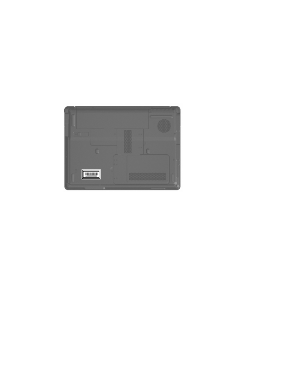
Component replacement procedures
This chapter provides removal and replacement procedures.
There are as many as 86 screws, in 12 different sizes, that must be removed, replaced, or loosened when
servicing the computer. Make special note of each screw size and location during removal and
replacement.
Serial number
Report the computer serial number to HP when requesting information or ordering spare parts. The serial
number is located on the bottom of the computer.
Component replacement procedures 51
Page 60
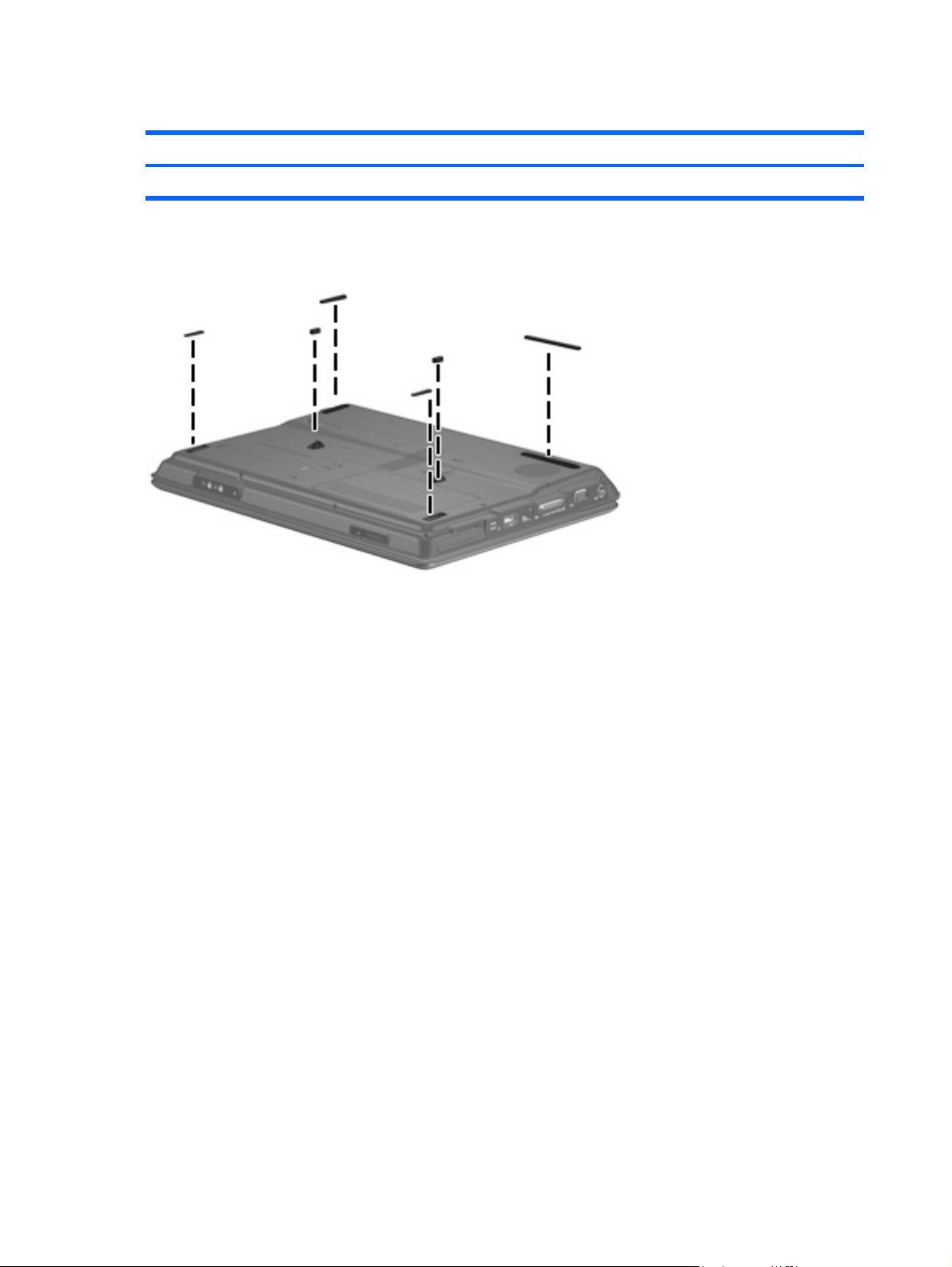
Computer feet
Description Spare part number
Rubber Feet Kit (includes base enclosure rubber feet and display bezel screw covers) 417096-001
The computer feet are adhesive-backed rubber pads. The feet attach to the base enclosure in the locations
illustrated below.
52 Chapter 4 Removal and replacement procedures
Page 61
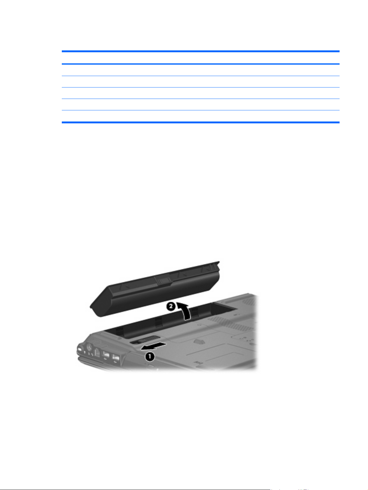
Battery
Description Spare part number
For use in computer models with Intel or AMD processors:
6-cell, 2.55-Ah Li-ion battery 441611-001
For use in computer models with Intel processors:
12-cell, 2.20-Ah Li-ion battery 452056-001
6-cell, 2.20-Ah Li-ion battery 452057-001
Before disassembling the computer, follow these steps:
Shut down the computer. If you are unsure whether the computer is off or in Hibernation, turn the
1.
computer on, and then shut it down through the operating system.
Disconnect all external devices connected to the computer.
2.
Disconnect the power from the computer by first unplugging the power cord from the AC outlet and
3.
then unplugging the AC adapter from the computer.
Remove the battery:
Turn the computer upside down on a flat surface.
1.
2. Slide the battery release latch (1) to release the battery.
3. Pivot the battery (2) upward and remove it from the computer.
To insert the battery, insert the rear edge of the battery into the battery bay and pivot the front edge
downward until the battery is seated. The battery release latch automatically locks the battery into place.
Component replacement procedures 53
Page 62

Hard drive
NOTE: All hard drive spare part kits include a hard drive bracket.
Description Spare part number
For use in computer models with Intel processors:
320-GB, 5400-rpm 459611-003
250-GB, 5400-rpm 453949-001
200-GB, 4200-rpm 455740-001
160-GB, 5400-rpm 452060-001
120-GB, 5400-rpm 452059-001
80-GB, 5400-rpm 452058-001
For use in computer models with AMD processors:
320-GB, 5400-rpm 459611-002
250-GB, 5400-rpm 455827-001
160-GB, 5400-rpm 453418-001
120-GB, 5400-rpm 453417-001
80-GB, 5400-rpm 453416-001
Hard drive hardware kit (contains screws, hard drive bracket, and connector; not illustrated) 453419-001
Before removing the hard drive, follow these steps:
Shut down the computer. If you are unsure whether the computer is off or in Hibernation, turn the
1.
computer on, and then shut it down through the operating system.
Disconnect all external devices connected to the computer.
2.
Disconnect the power from the computer by first unplugging the power cord from the AC outlet and
3.
then unplugging the AC adapter from the computer.
Remove the battery (see
4.
Battery on page 53).
Remove the hard drive:
Position the computer with the front toward you.
1.
2. Loosen the two Phillips PM2.0×5.0 captive screws (1) that secure the hard drive cover to the
computer.
54 Chapter 4 Removal and replacement procedures
Page 63

3. Lift the left side of the hard drive cover (2), swing it to right, and remove the cover. The hard drive
cover is included in the Door/Cover Kit, spare part number 417074-001.
4. Remove the two black Phillips PM2.5×4.0 screws (1) that secure the hard drive to the computer.
5. Use the Mylar tab (2) to lift the hard drive (3) until it disconnects from the computer.
Remove the hard drive from the hard drive bay.
6.
7. If it is necessary to replace the hard drive bracket, remove the four Phillips PM3.0×4.0 screws (1)
that secure the hard drive bracket to the hard drive.
Component replacement procedures 55
Page 64

8. Lift the bracket (2) straight up to remove it from the hard drive.
Reverse this procedure to reassemble and install the hard drive.
56 Chapter 4 Removal and replacement procedures
Page 65

WLAN module
Description Spare part number
802.11a/b/g/n WLAN modules:
For use in Antigua and Barbuda, Argentina, Aruba, the Bahamas, Barbados, Bermuda, Brunei,
Canada, the Cayman Islands, Chile, Colombia, Costa Rica, the Dominican Republic, Ecuador, El
Salvador, Guam, Guatemala, Haiti, Honduras, Hong Kong, India, Indonesia, Malaysia, Mexico,
Panama, Paraguay, Peru, Saudi Arabia, Taiwan, Uruguay, the United States, Venezuela, and Vietnam
For use in Austria, Azerbaijan, Bahrain, Belgium, Brazil, Bulgaria, Croatia, Cyprus, the Czech
Republic, Denmark, Egypt, Estonia, Finland, France, Georgia, Germany, Greece, Hungary, Iceland,
Ireland, Israel, Italy, Latvia, Lebanon, Liechtenstein, Lithuania, Luxembourg, Malta, Monaco, the
Netherlands, Norway, Oman, the Philippines, Poland, Portugal, Qatar, Romania, Russia, Serbia and
Montenegro, Singapore, Slovakia, Slovenia, South Africa, Spain, Sri Lanka, Sweden, Switzerland,
Turkey, Ukraine, the United Kingdom, and Uzbekistan
For use in Australia, New Zealand, Pakistan, the People's Republic of China, and South Korea 441086-003
For use in Japan 441086-291
For use in South Korea 441086-AD1
802.11a/b/g WLAN modules:
For use in Antigua and Barbuda, Argentina, Australia, the Bahamas, Barbados, Brunei, Canada,
Chile, the Dominican Republic, Guam, Guatemala, Hong Kong, India, Indonesia, Malaysia, Mexico,
New Zealand, Panama, Paraguay, Saudi Arabia, Taiwan, the United States, and Vietnam
For use in Aruba, Austria, Azerbaijan, Bahrain, Belgium, Bermuda, Brazil, Bulgaria, the Cayman
Islands, Colombia, Croatia, Cyprus, the Czech Republic, Denmark, Egypt, El Salvador, Estonia,
Finland, France, Georgia, Germany, Greece, Hungary, Iceland, Ireland, Italy, Jordan, Latvia,
Lebanon, Liechtenstein, Lithuania, Luxembourg, Malta, Monaco, the Netherlands, Norway, Oman,
the Philippines, Poland, Portugal, Romania, Russia, Serbia and Montenegro, Singapore, Slovakia,
Slovenia, South Africa, Spain, Sri Lanka, Sweden, Switzerland, Turkey, the United Kingdom, and
Uzbekistan
441086-001
441086-002
452063-001
452063-002
For use in Ecuador, Haiti, Honduras, Pakistan, the People's Republic of China, Peru, Qatar, South
Korea, Uruguay, and Venezuela
802.11b/g WLAN module for use in Thailand
Broadcom 4311AG 802.11a/b/g modules:
For use in the United States and Canada 441075-001
For use in Afghanistan, Albania, Algeria, Andorra, Angola, Antigua & Barbuda, Argentina, Armenia,
Aruba, Australia, Austria, Azerbaijan, the Bahamas, Bahrain, Bangladesh, Barbados, Belarus,
Belgium, Belize, Benin, Bermuda, Bhutan, Bolivia, Bosnia & Herzegovina Botswana, Brazil, the British
Virgin Islands, Brunei, Bulgaria, Burkina Faso, Burundi, Cambodia, Cameroon, Cape Verde, the
Central African Republic, Chad, Chile, Colombia, Comoros, the Congo, Costa Rica, Croatia, Cyprus,
the Czech Republic, Denmark, Djibouti, Dominica, the Dominican Republic, East Timor, Ecuador,
Egypt, El Salvador, Equitorial Guinea, Eritrea, Estonia, Ethiopia, Fiji, Finland, France, French Guiana,
Gabon, Gambia, Georgia, Germany, Ghana, Gibraltar, Greece, Grenada, Guadeloupe,
Guatemala, Guinea, Guinea-Bissau, Guyana, Haiti, Honduras, Hong Kong, Hungary, Iceland, India,
Indonesia, Ireland, Israel, Italy, the Ivory Coast, Jamaica, Jordan, Kazakhstan, Kenya, Kiribati, Kuwait,
Kyrgyzstan, Laos, Latvia, Lebanon, Lesotho, Liberia, Liechtenstein, Lithuania, Luxembourg, Macedonia,
Madagascar, Malawi, Malaysia, the Maldives, Mali, Malta, the Marshall Islands, Martinique,
Mauritania, Mauritius, Mexico, Micronesia, Monaco, Mongolia, Montenegro, Morocco,
Mozambique, Namibia, Nauru, Nepal, the Nether Antilles, the Netherlands, New Zealand,
Nicaragua, Niger, Nigeria, Norway, Oman, Palau, Panama, Papua New Guinea, Paraguay, the
People's Republic of China, Peru, the Philippines, Poland, Portugal, Qatar, the Republic of Moldova,
Romania, Russia, Rwanda, Samoa, San Marino, Sao Tome & Principe, Saudi Arabia, Senegal, Serbia
and Montenegro, the Seychelles, Sierra Leone, Singapore, Slovakia, Slovenia, the Solomon Islands,
Somalia, South Africa, South Korea, Spain, Sri Lanka, St. Kitts & Nevis, St. Lucia, St. Vincent &
452063-003
409407-004
441075-002
Component replacement procedures 57
Page 66

Description Spare part number
Grenadines, Suriname, Swaziland, Sweden, Switzerland, Taiwan, Tajikistan, Tanzania, Thailand,
Togo, Tonga, Trinidad & Tobago, Tunisia, Turkey, Turkmenistan, Tuvalu, Uganda, Ukraine, the United
Arab Emirates, the United Kingdom, Uruguay, Uzbekistan, Vanuatu, Venezuela, Vietnam, Yemen,
Zaire, Zambia, and Zimbabwe
For use in Japan 441075-291
Broadcom 802.11b/g WLAN modules:
For use in Canada, the Cayman Islands, Guam, Puerto Rico, the U.S. Virgin Islands, and the United
States
For use in Afghanistan, Albania, Algeria, Andorra, Angola, Antigua & Barbuda, Argentina, Armenia,
Aruba, Australia, Austria, Azerbaijan, the Bahamas, Bahrain, Bangladesh, Barbados, Belarus,
Belgium, Belize, Benin, Bermuda, Bhutan, Bolivia, Bosnia & Herzegovina Botswana, Brazil, the British
Virgin Islands, Brunei, Bulgaria, Burkina Faso, Burundi, Cambodia, Cameroon, Cape Verde, the
Central African Republic, Chad, Chile, Colombia, Comoros, the Congo, Costa Rica, Croatia, Cyprus,
the Czech Republic, Denmark, Djibouti, Dominica, the Dominican Republic, East Timor, Ecuador,
Egypt, El Salvador, Equitorial Guinea, Eritrea, Estonia, Ethiopia, Fiji, Finland, France, French Guiana,
Gabon, Gambia, Georgia, Germany, Ghana, Gibraltar, Greece, Grenada, Guadeloupe,
Guatemala, Guinea, Guinea-Bissau, Guyana, Haiti, Honduras, Hong Kong, Hungary, Iceland, India,
Indonesia, Ireland, Israel, Italy, the Ivory Coast, Jamaica, Jordan, Kazakhstan, Kenya, Kiribati, Kuwait,
Kyrgyzstan, Laos, Latvia, Lebanon, Lesotho, Liberia, Liechtenstein, Lithuania, Luxembourg, Macedonia,
Madagascar, Malawi, Malaysia, the Maldives, Mali, Malta, the Marshall Islands, Martinique,
Mauritania, Mauritius, Mexico, Micronesia, Monaco, Mongolia, Montenegro, Morocco,
Mozambique, Namibia, Nauru, Nepal, the Nether Antilles, the Netherlands, New Zealand,
Nicaragua, Niger, Nigeria, Norway, Oman, Palau, Panama, Papua New Guinea, Paraguay, the
People's Republic of China, Peru, the Philippines, Poland, Portugal, Qatar, the Republic of Moldova,
Romania, Russia, Rwanda, Samoa, San Marino, Sao Tome & Principe, Saudi Arabia, Senegal, Serbia
and Montenegro, the Seychelles, Sierra Leone, Singapore, Slovakia, Slovenia, the Solomon Islands,
Somalia, South Africa, South Korea, Spain, Sri Lanka, St. Kitts & Nevis, St. Lucia, St. Vincent &
Grenadines, Suriname, Swaziland, Sweden, Switzerland, Taiwan, Tajikistan, Tanzania, Thailand,
Togo, Tonga, Trinidad & Tobago, Tunisia, Turkey, Turkmenistan, Tuvalu, Uganda, Ukraine, the United
Arab Emirates, the United Kingdom, Uruguay, Uzbekistan, Vanuatu, Venezuela, Vietnam, Yemen,
Zaire, Zambia, and Zimbabwe
For use in Japan 441090-291
441090-001
441090-002
802.11n WLAN modules:
For use in the United States and Canada 436255-001
For use in the Argentina, Australia, Belize, Bolivia, Brazil, Chile, Columbia, Costa Rica, Ecuador, El
Salvador, Guatemala, Honduras, Hong Kong, Indonesia, Nicaragua, Paraguay, the People's
Republic of China, Peru, South Korea, Taiwan, Thailand, Uruguay, Venezuela
For use in Japan 436256-291
Broadcom BCM4312 WLAN b/g modules:
For use in Canada, Cayman Islands, Guam, Puerto Rico, the United States, and the Virgin Islands 459263-001
For use in Afghanistan, Albania, Algeria, Andorra, Angola, Antigua & Barbuda, Argentina, Armenia,
Australia, Austria, Azerbaijan, Bahamas, Bahrain, Bangladesh, Barbados, Belarus, Belgium, Belize,
Benin, Bhutan, Bolivia, Bosnia & Herzegovina, Botswana, Brazil, Brunei, Bulgaria, Burkina, Faso
Burundi, Cambodia, Cameroon, Cape Verde, Central African Republic, Chad, Chile, People's
Republic of China, Colombia, Comoros, Congo, Costa Rica, Croatia, Cyprus, Czech Republic, Zaire,
Denmark, Djibouti, Dominica, Dominican Republic, Ecuador, Egypt, El Salvador, Equitorial Guinea,
Eritrea, Estonia, Ethiopia, Fiji, Finland, France, Gabon, Gambia, Georgia, Germany, Ghana,
Gibraltar, Greece, Grenada, Guatemala, Guinea, Guinea-Bissau, Guyana, Haiti, Honduras, Hong
Kong, Hungary, Iceland, India, Indonesia, Ireland, Israel, Italy, Ivory Coast, Jamaica, Japan, Jordan,
Kazakhstan, Kenya, Kiribati, Kuwait, Kyrgyzstan, Laos, Latvia, Lebanon, Lesotho, Liberia, Martinique,
British Virgin Islands, French Guiana, Guadeloupe, Nether Antilles, Aruba, Bermuda, Syria,
Liechtenstein, Lithuania, Luxembourg, Macedonia, Madagascar, Malawi, Malaysia, Maldives, Mali,
58 Chapter 4 Removal and replacement procedures
436256-001
459263-002
Page 67

Description Spare part number
Malta, Marshall Islands, Mauritania, Mauritius, Mexico, Micronesia, Monaco, Mongolia,
Montenegro, Morocco, Mozambique, Namibia, Nauru, Nepal, Netherlands, New Zealand,
Nicaragua, Niger, Nigeria, Norway, Oman, Pakistan, Palau, Panama, Papua New Guinea,
Paraguay, Peru, Philippines, Poland, Portugal, Qatar, Republic of Moldova, Romania, Russia,
Rwanda, Samoa, San Marino, Sao Tome & Principe, Saudi Arabia, Senegal, Serbia and Montenegro,
Seychelles, Sierra Leone, Singapore, Slovakia, Slovenia, Solomon Islands, Somalia, South Africa,
South Korea, Spain, Sri Lanka, St. Kitts & Nevis, St. Lucia, St. Vincent & Grenadines,. Suriname,
Swaziland, Sweden, Switzerland, Taiwan, Tajikistan, Tanzania, Thailand, East Timor, Togo, Tonga,
Trinidad & Tobago, Tunisia, Turkey, Turkmenistan, Tuvalu, Uganda, Ukraine, United Arab Emirates,
United Kingdom, Uruguay, Uzbekistan, Vanuatu, Venezuela, Vietnam, Yemen, Zambia, and
Zimbabwe
Before removing the WLAN module, follow these steps:
Shut down the computer. If you are unsure whether the computer is off or in Hibernation, turn the
1.
computer on, and then shut it down through the operating system.
Disconnect all external devices connected to the computer.
2.
Disconnect the power from the computer by first unplugging the power cord from the AC outlet and
3.
then unplugging the AC adapter from the computer.
Remove the battery (see
4.
Remove the hard drive cover (see
5.
Battery on page 53).
Hard drive on page 54).
Remove the WLAN module:
Position the computer with the front toward you.
1.
2. Loosen the Phillips PM2.0×5.0 captive screw (1) that secures the wireless module compartment cover
to the computer.
3. Lift the right edge of the wireless module compartment cover (2), swing it to the left, and remove the
cover. The wireless module compartment cover is included in the Door/Cover Kit, spare part number
417074-001.
4. Disconnect the two WLAN antenna cables (1) from the WLAN module.
Component replacement procedures 59
Page 68

NOTE: The black WLAN antenna cable is connected to the WLAN module “Main” terminal. The
white WLAN antenna cable is connected to the WLAN module “Aux” terminal.
NOTE: Computer models equipped with an 802.11a/b/g/n WLAN module will have an
additional wireless antenna cable (2), yellow in color.
5. Remove the two Phillips PM2.0×3.0 screws (3) that secure the WLAN module to the computer. (The
edge of the module opposite the slot rises away from the computer.)
6. Remove the WLAN module (4) by pulling it away from the slot at an angle.
NOTE: WLAN modules are designed with a notch (5) to prevent incorrect installation into the
WLAN module slot.
Reverse this procedure to install a WLAN module.
60 Chapter 4 Removal and replacement procedures
Page 69
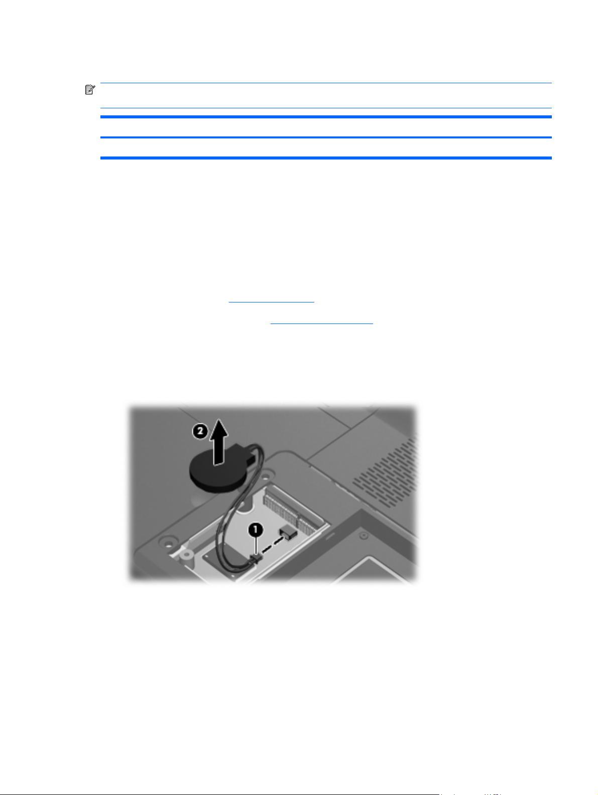
RTC battery
NOTE: Removing the RTC battery and leaving it uninstalled for 5 or more minutes causes all passwords
and CMOS settings to be cleared.
Description Spare part number
RTC battery (includes 2-sided tape) 417076-001
Before removing the RTC battery, follow these steps:
Shut down the computer. If you are unsure whether the computer is off or in Hibernation, turn the
1.
computer on, and then shut it down through the operating system.
Disconnect all external devices connected to the computer.
2.
Disconnect the power from the computer by first unplugging the power cord from the AC outlet and
3.
then unplugging the AC adapter from the computer.
Remove the battery (see
4.
Remove the hard drive cover (see
5.
Battery on page 53).
Hard drive on page 54).
Remove the RTC battery:
1. Disconnect the RTC battery cable (1) from the system board.
2. Remove the RTC battery (2).
Reverse this procedure to install the RTC battery.
Component replacement procedures 61
Page 70

Memory module
Description Spare part number
For use in computer models with Intel processors:
2048-MB (667-MHz, PC2-5300, 1-DIMM) 455739-001
1024-MB (667-MHz, PC2-5300, 1-DIMM) 452062-001
512-MB (667-MHz, PC2-5300, 1-DIMM) 452061-001
For use in computer models with AMD processors:
2048-MB (667-MHz, PC-5300, 1-DIMM) 448151-002
1024-MB (667-MHz, PC2-5300, 1-DIMM) 453415-001
512-MB (667-MHz, PC2-5300, 1-DIMM) 453414-001
Before removing the memory module, follow these steps:
Shut down the computer. If you are unsure whether the computer is off or in Hibernation, turn the
1.
computer on, and then shut it down through the operating system.
Disconnect all external devices connected to the computer.
2.
Disconnect the power from the computer by first unplugging the power cord from the AC outlet and
3.
then unplugging the AC adapter from the computer.
Remove the battery (see
4.
Battery on page 53).
Remove the memory module:
Position the computer with the front toward you.
1.
2. Loosen the two Phillips PM2.0×5.0 captive screws (1) that secure the memory module compartment
cover to the computer.
3. Lift the right side of the cover (2), swing it to the left, and remove the cover. The memory module
compartment cover is included in the Door/Cover Kit, spare part number 417074-001.
62 Chapter 4 Removal and replacement procedures
Page 71

4. Spread the retaining tabs (1) on each side of the memory module slot to release the memory module.
(The edge of the module opposite the slot rises away from the computer.)
5. Remove the module (2) by pulling it away from the slot at an angle.
NOTE: Memory modules are designed with a notch (3) to prevent incorrect installation into the
memory module slot.
Reverse this procedure to install a memory module.
Component replacement procedures 63
Page 72

Optical drive
NOTE: All optical drive spare part kits include an optical drive bezel.
Description Spare part number
For use in computer models with Intel processors:
DVD±RW and CD-RW Super Multi Double-Layer Combo Drive with LightScribe 452055-001
DVD±RW and CD-RW Super Multi Double-Layer Combo Drive 452054-001
DVD/CD-RW Combo Drive 452053-001
For use in computer models with AMD processors:
DVD±RW and CD-RW Super Multi Double-Layer Combo Drive with LightScribe 455830-002
DVD±RW and CD-RW Super Multi Double-Layer Combo Drive 455829-002
DVD/CD-RW Combo Drive 455828-002
Before removing the optical drive, follow these steps:
Shut down the computer. If you are unsure whether the computer is off or in Hibernation, turn the
1.
computer on, and then shut it down through the operating system.
Disconnect all external devices connected to the computer.
2.
Disconnect the power from the computer by first unplugging the power cord from the AC outlet and
3.
then unplugging the AC adapter from the computer.
Remove the battery (see
4.
Battery on page 53).
Remove the optical drive:
Position the computer with right side toward you.
1.
2. Remove the Phillips PM2.5×9.0 screw (1) that secures the optical drive to the computer.
3. Insert a thin tool, such as a paper clip (2), into the release access. (The optical drive media tray is
partially ejected from the optical drive.)
64 Chapter 4 Removal and replacement procedures
Page 73

4. Use the media tray frame to remove the optical drive (3).
If it is necessary to replace the optical drive bracket, position the optical drive with the optical drive
5.
bracket toward you.
6. Remove the two Phillips PM2.0×3.0 screws (1) that secure the optical drive bracket to the optical
drive.
7. Remove the optical drive bracket (2).
Reverse the above procedure to reassemble and install the optical drive.
Component replacement procedures 65
Page 74

Keyboard
For use in: Spare part number For use in: Spare part number
Belgium 448615-021 Portugal 448615-131
Brazil 448615-201 Russia 448615-251
Canadian French 448615-121 Saudi Arabia 448615-171
Denmark, Finland, Norway, and
Sweden
France 448615-051 Spain 448615-071
Germany 448615-041 Switzerland 448615-111
Greece 448615-DJ1 Taiwan 448615-AB1
Israel 448615-BB1 Thailand 448615-281
Italy 448615-061 Turkey 448615-141
Latin America 448615-161 The United Kingdom 448615-031
The Netherlands and Europe 448615-B31 The United States 448615-001
448615-DH1 South Korea 448615-AD1
Before removing the keyboard, follow these steps:
Shut down the computer. If you are unsure whether the computer is off or in Hibernation, turn the
1.
computer on, and then shut it down through the operating system.
Disconnect all external devices connected to the computer.
2.
Disconnect the power from the computer by first unplugging the power cord from the AC outlet and
3.
then unplugging the AC adapter from the computer.
Remove the battery (see
4.
Battery on page 53).
Remove the keyboard:
Turn the computer upside down, with the front toward you.
1.
66 Chapter 4 Removal and replacement procedures
Page 75
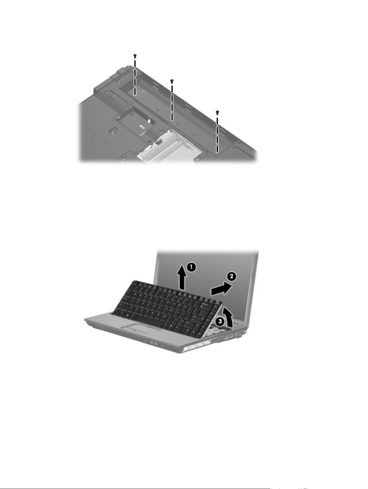
Remove the three Phillips PM2.5×7.0 screws that secure the keyboard to the computer.
2.
Turn the computer display-side up, with the front toward you.
3.
Open the computer as far as possible.
4.
5. Lift the rear edge of the keyboard (1) until it rests at an angle.
6. Release the keyboard (2) by sliding it back to disengage the tabs on the front edge of the keyboard
from the top cover.
7. Swing the rear edge of the keyboard (3) up and forward until it rests on the palm rest.
Component replacement procedures 67
Page 76

8. Release the zero insertion force (ZIF) connector (1) to which the keyboard cable is attached and
disconnect the keyboard cable (2) from the system board.
Remove the keyboard.
9.
Reverse this procedure to install the keyboard.
68 Chapter 4 Removal and replacement procedures
Page 77
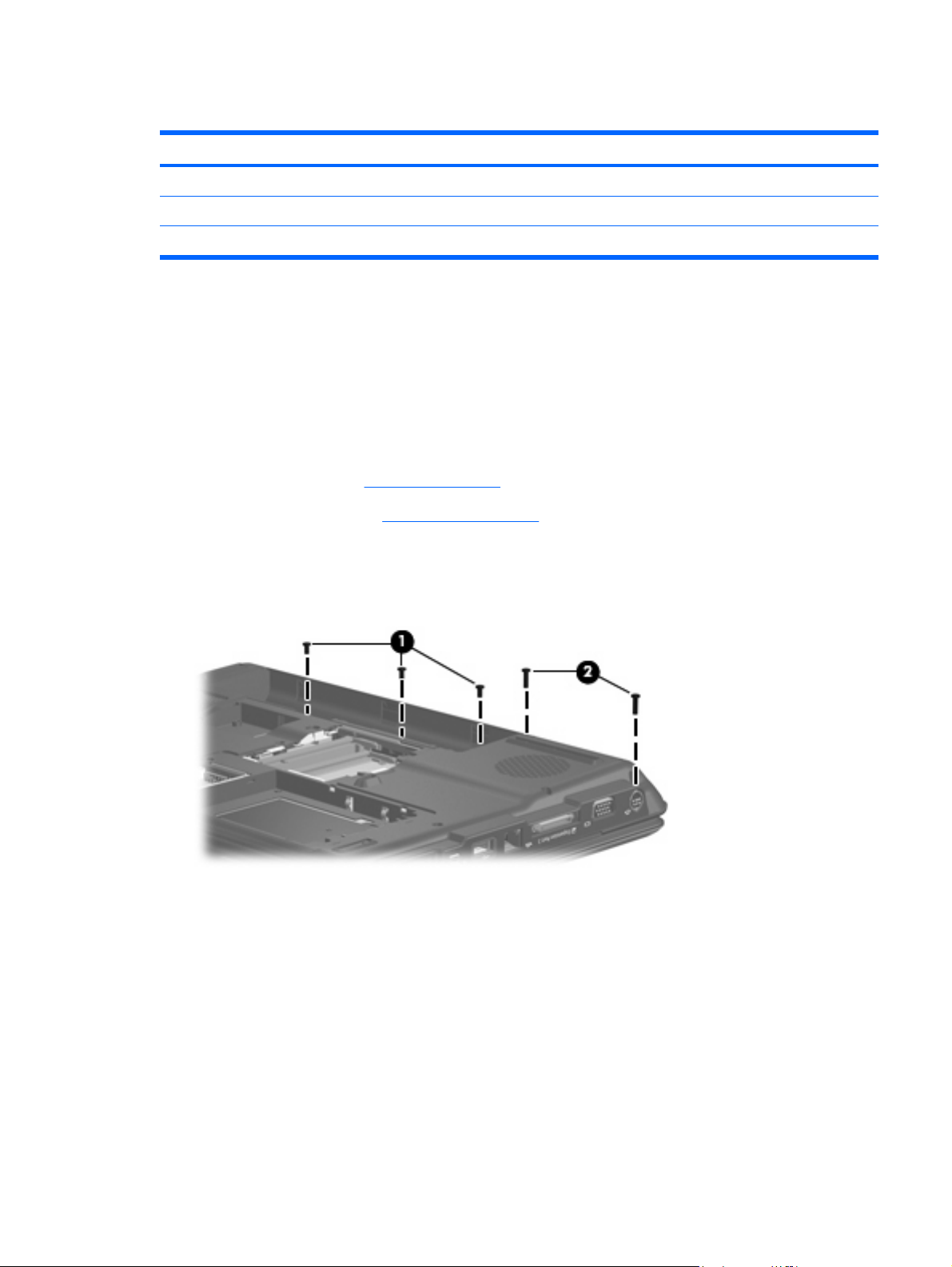
Switch cover
Description Spare part number
Switch cover (includes power button board and cable, LED board, and LED board cable
For use in computer models with Intel processors or full-featured models with AMD processors 451313-001
For use in defeatured computer models with AMD processors 417078-001
Before removing the switch cover, follow these steps:
Shut down the computer. If you are unsure whether the computer is off or in Hibernation, turn the
1.
computer on, and then shut it down through the operating system.
Disconnect all external devices connected to the computer.
2.
Disconnect the power from the computer by first unplugging the power cord from the AC outlet and
3.
then unplugging the AC adapter from the computer.
Remove the battery (see
4.
Remove the keyboard (see
5.
Battery on page 53).
Keyboard on page 66).
Remove the switch cover:
1. Remove the two Phillips PM2.5×9.0 screws (1) and the three black Phillips PM2.0×5.0 screws (2)
that secure the switch cover to the computer.
Turn the computer display-side up, with the front toward you.
2.
Open the computer as far as possible.
3.
4. Disconnect the power button board cable (1) from the system board.
Component replacement procedures 69
Page 78
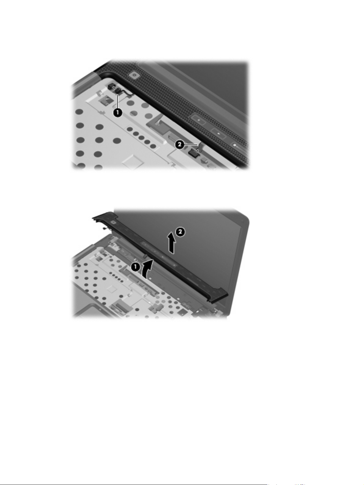
5. Release the ZIF connector to which the LED board cable (2) is connected and disconnect the cable
from the system board.
6. Lift the front edge of the switch cover (1) to disengage it from the computer.
7. Remove the switch cover (2).
Reverse this procedure to install the switch cover.
70 Chapter 4 Removal and replacement procedures
Page 79

Display assembly
Description Spare part number
14.1-inch, WXGA, BrightView display assembly for use in computer models with Intel or AMD
processors without a camera module (includes microphones)
14.1-inch, WXGA, BrightView display assembly for use only in defeatured computer models with AMD
processors without a camera module
14.1-inch, WXGA, BrightView display assembly for use in computer models with Intel or AMD
processors without a camera module (includes microphones)
14.1-inch, WXGA, BrightView display assembly for use in computer models with Intel or AMD
processors without a camera module (does not include microphones)
14.1-inch, WXGA, BrightView display assembly for use in computer models with Intel or AMD
processors with a camera module (includes microphones)
448611-001
451163-001
457348-001
457349-001
462761-001
Before removing the display assembly, follow these steps:
Shut down the computer. If you are unsure whether the computer is off or in Hibernation, turn the
1.
computer on, and then shut it down through the operating system.
Disconnect all external devices connected to the computer.
2.
Disconnect the power from the computer by first unplugging the power cord from the AC outlet and
3.
then unplugging the AC adapter from the computer.
Remove the battery (see
4.
Battery on page 53).
Disconnect the wireless antenna cables from the WLAN module (see
5.
Remove the following components:
6.
Keyboard (see
a.
Switch cover (see
b.
Keyboard on page 66)
Switch cover on page 69)
Remove the display assembly:
Close the computer and turn it upside down, with the front toward you.
1.
WLAN module on page 57).
Component replacement procedures 71
Page 80

Remove the Phillips PM2.5×9.0 screw that secures the display assembly to the computer.
2.
Turn the computer display-side up, with the front toward you.
3.
Open the display as far as possible.
4.
Disconnect the following cables:
5.
(1) Display panel cable
(2) Display switch module cable
(3) Microphone cable
6. Remove the wireless antenna cables (4) from the hole in the system board and the routing
channels (5) built into the top cover.
CAUTION: Support the display assembly when removing the following screws. Failure to support
the display assembly can result in damage to the display assembly and other computer components.
7. Remove the five black Phillips PM2.5×7.0 screws (1) that secure the display assembly to the
computer.
72 Chapter 4 Removal and replacement procedures
Page 81

8. Remove the display assembly (2).
If it is necessary to replace any of the display assembly internal components, remove the following
9.
screw covers and screws. The display rubber screw covers are included in the Rubber Feet Kit, spare
part number 417096-001.
(1) Six rubber screw covers on the display bezel top edge and bottom edge corners
(2) Two rubber screw covers on the display bezel bottom edge
(3) Eight Phillips PM2.5×7.0 screws
NOTE: There are two different sizes of display bezel rubber screw covers. The thicker covers (2)
must be installed in the bottom center screw holes.
10. Flex the inside edges of the left and right sides (1) and the top and bottom sides (2) of the display
bezel until the bezel disengages from the display enclosure.
Component replacement procedures 73
Page 82
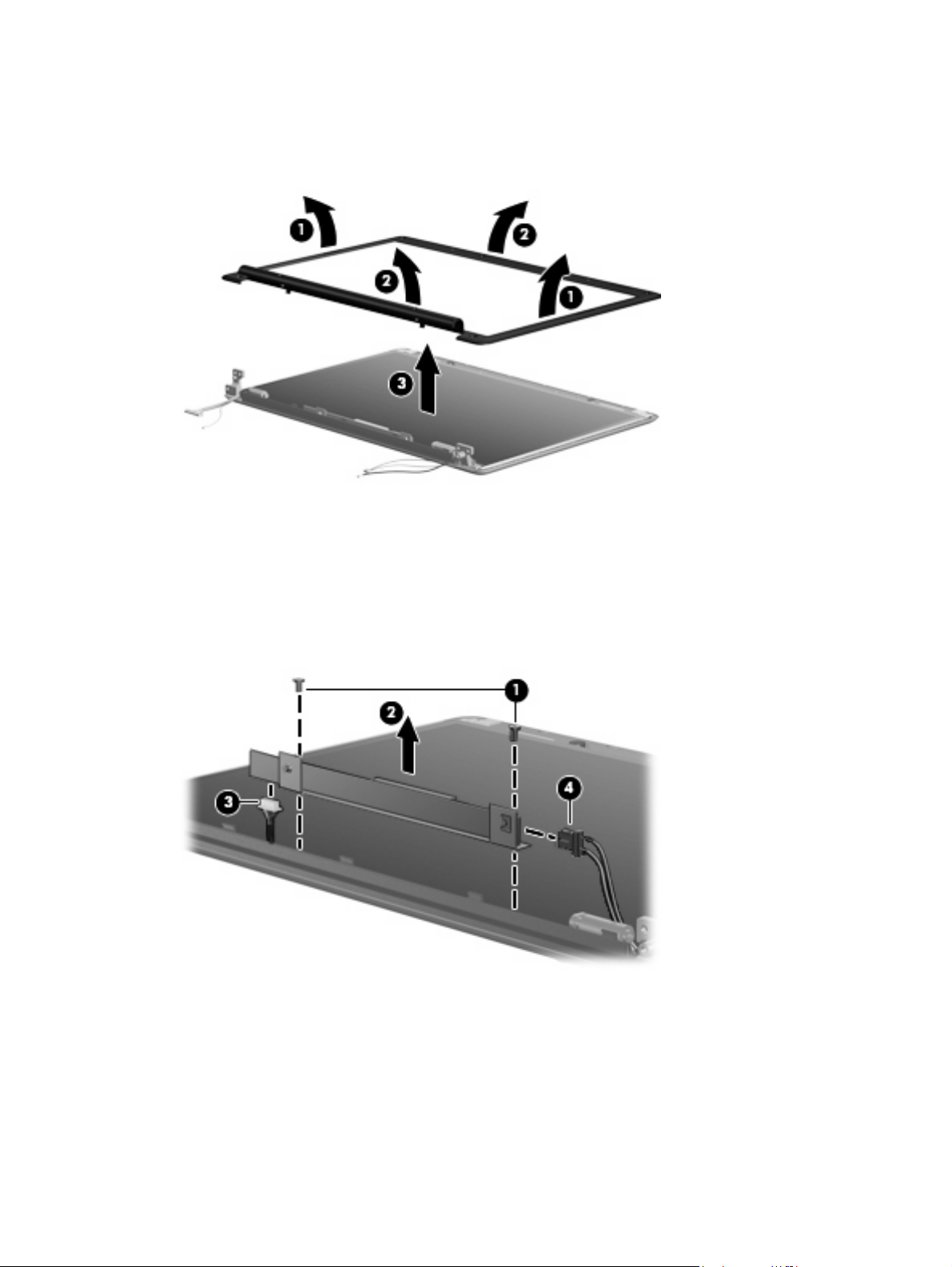
11. Remove the display bezel (3). The display bezel is available using spare part number 448613-001
including microphone for computers with Intel or AMD processors without a camera module,
461913-001 for computers including microphone with AMD processors with a camera module, or
455820-001 not including microphone for computers with AMD processors.
If it is necessary to replace the display inverter, remove the two black Phillips PM2.5×5.0 screws
12.
(1) that secure the inverter to the display enclosure.
13. Release the inverter (2) as far as the display panel cable and the backlight cable will allow.
14. Disconnect the display panel cable (3) and the backlight cable (4) from the display inverter. The
display inverter is available using spare part number 417097-001 for computers with Intel
processors, 455821-001 for computers with AMD processors.
Remove the inverter and inverter bracket.
15.
16. Remove the black Phillips PM2.5×5.0 screw (1) that secures the inverter to the inverter bracket.
74 Chapter 4 Removal and replacement procedures
Page 83
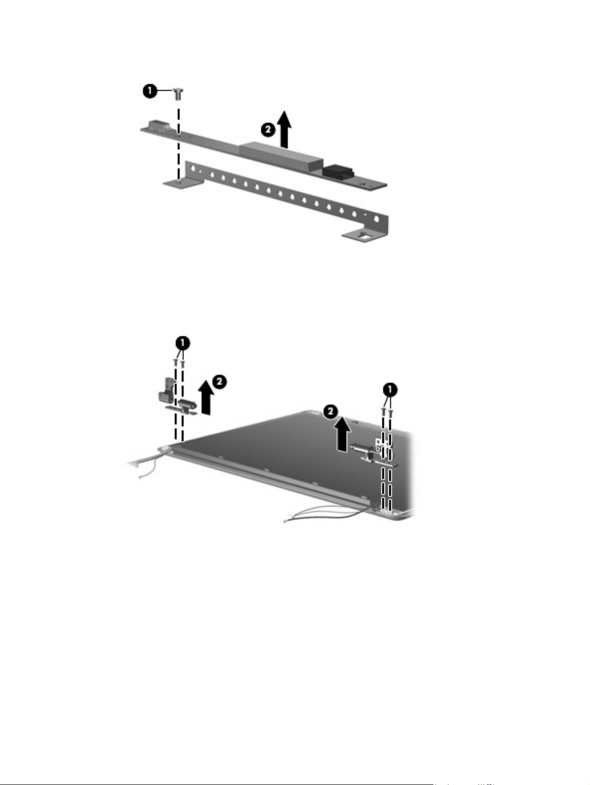
17. Remove the inverter (2) from the bracket.
If it is necessary to replace the display hinges, remove the two black Phillips PM2.5×5.0 screws
18.
(1) that secure each hinge to the display enclosure.
19. Remove the display hinges (2) from the display enclosure. The display hinges are available using
spare part number 417103-001 for computers with Intel processors, 455822-001 for computers
with AMD processors.
If it is necessary to replace the display switch module, remove the black Phillips PM2.5×5.0
20.
screw (1) that secures the display switch module to the display enclosure.
Component replacement procedures 75
Page 84

21. Remove the display switch module (2). The display switch module is included in the Display Hinge
Kit, spare part number 417103-001 for computers with Intel processors, 455822-001 for computers
with AMD processors.
If it is necessary to replace the display panel, remove the display panel from the display enclosure.
22.
The display panel is available using the spare part number 448602-001 for computers with Intel
processors, 455810-001 for computers with AMD processors.
If it is necessary to replace the wireless antenna transceivers and cables, remove the Phillips
23.
PM2.5×4.0 screw (1) that secures each transceiver to the display enclosure.
24. Remove the wireless antenna cables from the clips (2) built into the display enclosure.
25. Detach the wireless antenna transceivers (3) from the display enclosure.
76 Chapter 4 Removal and replacement procedures
Page 85

26. Remove the wireless antenna transceivers and cables (4) from the display enclosure. The wireless
antenna transceivers and cables are included in the Wireless Antenna Kit, spare part number
417107-001.
27. If it is necessary to replace the microphone receivers and cables, release the retention tabs (1) built
into the display enclosure that secure the microphone cables to the display enclosure.
28. Remove the microphone receivers (2) from the clips in the display enclosure.
29. Remove the microphone cables (3) from the display enclosure. The microphone receivers and cables
are included in the Display Cable Kit, spare part number 448614-001 for computers with Intel
processors, 458656-001 for computers with AMD processors.
Reverse this procedure to reassemble and install the display assembly.
Camera module
If it has been determined that the camera module is the component that must be replaced to complete the
computer repair, the display assembly does not have to be removed. Follow the procedures in this section
to replace the camera module. For information on replacing the display assembly and other display
assembly internal components, see
Display assembly on page 71.
Component replacement procedures 77
Page 86

Description Spare part number
Camera module (includes camera module bracket and 2-sided tape) 453673-001
Before removing the camera module, follow these steps:
Shut down the computer. If you are unsure whether the computer is off or in Hibernation, turn the
1.
computer on, and then shut it down through the operating system.
Disconnect all external devices connected to the computer.
2.
Disconnect the power from the computer by first unplugging the power cord from the AC outlet and
3.
then unplugging the AC adapter from the computer.
Remove the battery (see
4.
Battery on page 53).
Remove the camera module:
Turn the computer display-side up, with the front toward you.
1.
Open the computer as far as it will open.
2.
3. Remove the four rubber screw covers (1) on the display bezel top edge. The display rubber screw
covers are included in the Rubber Feet Kit, spare part number 417096-001.
4. Remove the four Phillips PM2.5×7.0 screws (2) that secure the display bezel top edge to the display
assembly.
5. Flex the inside edges of the left and right sides (1) and the top edge (2) of the display bezel until
the bezel disengages from the display enclosure.
78 Chapter 4 Removal and replacement procedures
Page 87

6. Release the display bezel top edge (3). Display bezels are available using the following spare part
numbers:
448613-001 (for use with computer models with AMD processors with a camera module;
●
includes microphone; includes openings for camera module and microphones)
462525-001 (for use only with full-featured computer models with Intel processors; includes
●
openings for microphones)
457351-001 (for use only with defeatured computer models with Intel processors; includes
●
openings for microphones)
7. Release the camera module assembly (1) from the display enclosure as far as the camera module
cable allows.
8. Disconnect the camera module cable (2) from the camera module.
Turn the camera module assembly upside down.
9.
Component replacement procedures 79
Page 88
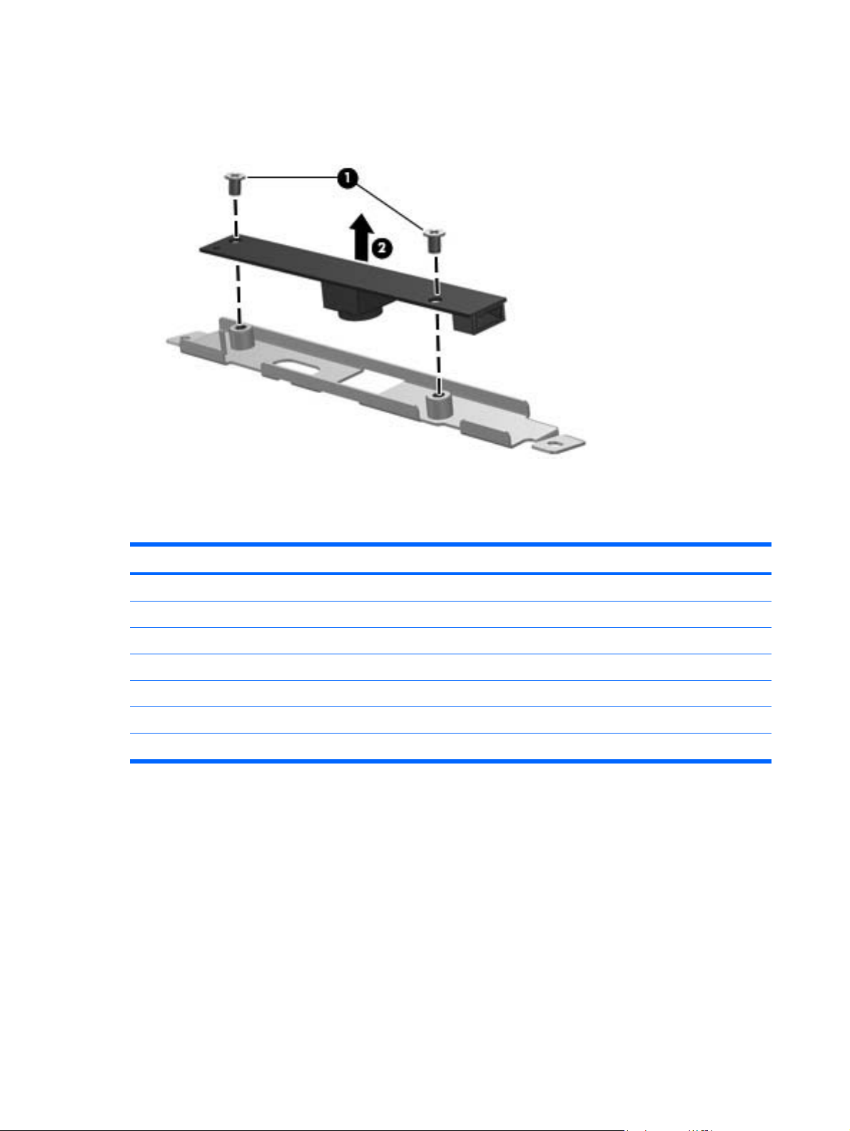
10. Remove the two Phillips PM2.0×3.0 screws (1) that secure the camera module to the camera module
bracket.
11. Remove the camera module (2) from the bracket.
Reverse this procedure to install the camera module.
Top cover
Description Spare part number
Top cover (includes TouchPad and cable)
For use only in full-featured computer models with Intel processors and a camera module 462524-001
For use in full-featured computer models with Intel processors without a camera module 448620-001
For use in full-featured computer models with AMD processors 455857-001
For use in defeatured computer models with AMD processors 417091-001
For use only in defeatured computer models with Intel processors 460947-001
For use only in defeatured computer models with Intel processors and a card reader 461267-001
Before removing the top cover, follow these steps:
1.
2.
3.
Shut down the computer. If you are unsure whether the computer is off or in Hibernation, turn the
computer on, and then shut it down through the operating system.
Disconnect all external devices connected to the computer.
Disconnect the power from the computer by first unplugging the power cord from the AC outlet and
then unplugging the AC adapter from the computer.
80 Chapter 4 Removal and replacement procedures
Page 89
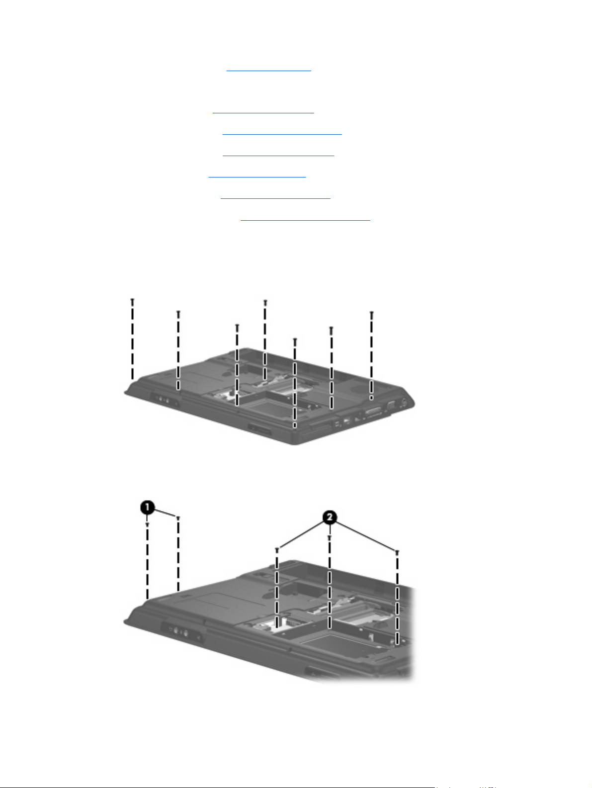
Remove the battery (see
4.
Remove the following components:
5.
Battery on page 53).
Hard drive (see
a.
WLAN cover (see
b.
Optical drive (see
c.
Keyboard (see
d.
Switch cover (see
e.
Display assembly (see
f.
Hard drive on page 54)
WLAN module on page 57)
Optical drive on page 64)
Keyboard on page 66)
Switch cover on page 69)
Display assembly on page 71)
Remove the top cover:
Turn the computer upside down, with the front toward you.
1.
Remove the seven Phillips PM2.5×9.0 screws that secure the top cover to the computer.
2.
3. Remove the two Phillips PM2.0×3.0 screws (1) and the three Phillips PM2.0×5.0 screws (2) that
secure the top cover to the computer.
Turn the computer right-side up, with the front toward you.
4.
Component replacement procedures 81
Page 90
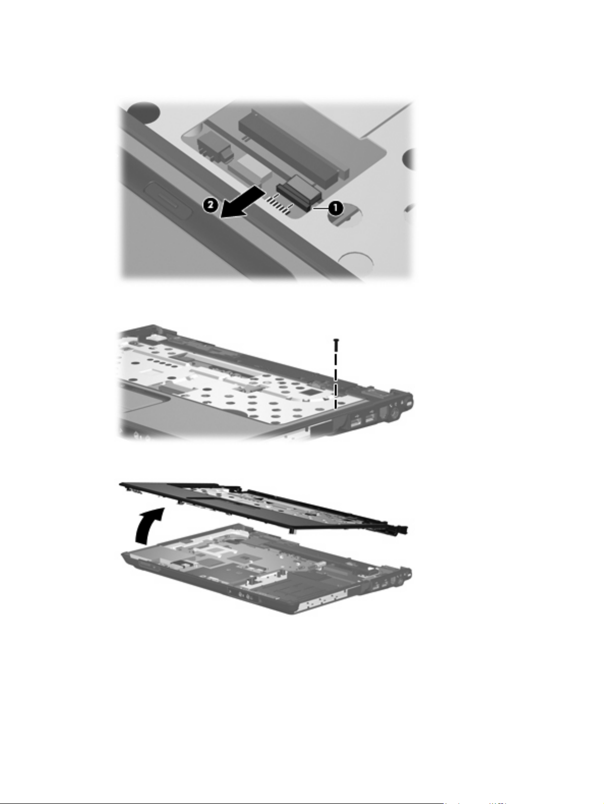
5. Release the ZIF connector (1) to which the TouchPad cable is connected and disconnect the cable
(2) from on the system board.
Remove the Phillips PM2.5×9.0 screw that secures the top cover to the computer.
6.
Lift the front edge of the top cover and remove it.
7.
Reverse this procedure to install the top cover.
82 Chapter 4 Removal and replacement procedures
Page 91

TouchPad
Description Spare part number
TouchPad for use only in computer models with Intel processors (includes TouchPad bracket and
TouchPad cable)
TouchPad for use only in computer models with AMD processors (includes TouchPad bracket and
TouchPad cable)
451341-001
455858-001
Before removing the TouchPad, follow these steps:
Shut down the computer. If you are unsure whether the computer is off or in Hibernation, turn the
1.
computer on, and then shut it down through the operating system.
Disconnect all external devices connected to the computer.
2.
Disconnect the power from the computer by first unplugging the power cord from the AC outlet and
3.
then unplugging the AC adapter from the computer.
Remove the battery (see
4.
Remove the following components:
5.
Hard drive (see
a.
WLAN cover (see
b.
Optical drive (see
c.
Battery on page 53).
Hard drive on page 54)
WLAN module on page 57)
Optical drive on page 64)
Keyboard (see
d.
Switch cover (see
e.
Display assembly (see
f.
Top cover (see
g.
Keyboard on page 66)
Switch cover on page 69)
Display assembly on page 71)
Top cover on page 80)
Remove the TouchPad:
Turn the top cover upside down, with the front toward you.
1.
2. Remove the five Phillips PM2.0×3.0 screws (1) that secure the TouchPad assembly to the top cover.
Component replacement procedures 83
Page 92

3. Remove the TouchPad bracket (2) and TouchPad board (3) from the top cover.
4. Remove the two Phillips PM2.0×2.0 screws (1) that secure the TouchPad board to the TouchPad
bracket.
5. Remove the TouchPad board (2) from the TouchPad bracket.
Reverse the above procedure to reassemble and install the TouchPad.
84 Chapter 4 Removal and replacement procedures
Page 93

Wireless switch board
Description Spare part number
Wireless switch board (includes wireless switch board cable) 417092-001
Before removing the wireless switch board, follow these steps:
Shut down the computer. If you are unsure whether the computer is off or in Hibernation, turn the
1.
computer on, and then shut it down through the operating system.
Disconnect all external devices connected to the computer.
2.
Disconnect the power from the computer by first unplugging the power cord from the AC outlet and
3.
then unplugging the AC adapter from the computer.
Remove the battery (see
4.
Remove the following components:
5.
Hard drive (see
a.
WLAN cover (see
b.
Optical drive (see
c.
Keyboard (see
d.
Switch cover (see
e.
Display assembly (see
f.
Top cover (see
g.
Battery on page 53).
Hard drive on page 54)
WLAN module on page 57)
Optical drive on page 64)
Keyboard on page 66)
Switch cover on page 69)
Display assembly on page 71)
Top cover on page 80)
Remove the wireless switch board:
1. Disconnect the wireless switch board cable (1) from the system board.
2. Remove the two Phillips PM2.0×3.0 screws (2) t hat secu re t he wireless switch board to the computer.
Component replacement procedures 85
Page 94

3. Remove the wireless switch board (3).
Reverse the above procedure to install the wireless switch board.
86 Chapter 4 Removal and replacement procedures
Page 95

Modem module
Description Spare part number
Modem module (includes modem module cable) 463971-001
Modem module cable 455847-001
Before removing the modem module, follow these steps:
Shut down the computer. If you are unsure whether the computer is off or in Hibernation, turn the
1.
computer on, and then shut it down through the operating system.
Disconnect all external devices connected to the computer.
2.
Disconnect the power from the computer by first unplugging the power cord from the AC outlet and
3.
then unplugging the AC adapter from the computer.
Remove the battery (see
4.
Remove the following components:
5.
Hard drive (see
a.
WLAN cover (see
b.
Optical drive (see
c.
Keyboard (see
d.
Switch cover (see
e.
Display assembly (see
f.
Top cover (see
g.
Battery on page 53).
Hard drive on page 54)
WLAN module on page 57)
Optical drive on page 64)
Keyboard on page 66)
Switch cover on page 69)
Display assembly on page 71)
Top cover on page 80)
Remove the modem module:
1. Disconnect the modem module cable (1) from the modem module.
2. Remove the Phillips PM2.0×5.0 screw (2) that secures the modem module to the system board.
Component replacement procedures 87
Page 96
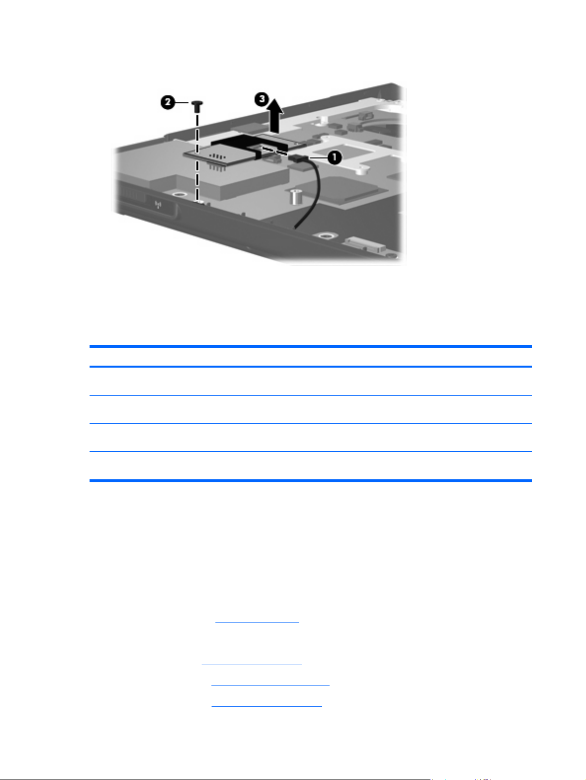
3. Lift up on the front of the modem module (3) to disconnect it from the system board.
Remove the modem module.
4.
Reverse the above procedure to install the modem module.
Audio board
Description Spare part number
Audio board for use only in full-featured computer models without a camera module (includes audio
connectors, infrared lens, and audio board cable)
Audio board for use only in defeatured computer models with AMD processors and without a camera
module (includes audio connectors, infrared lens, and audio board cable)
Audio board for use only in full-featured computer models with a camera module (includes audio
connectors, infrared lens, and audio board cable)
Audio board for use only in defeatured computer models with AMD processors and with a camera
module (includes audio connectors, infrared lens, and audio board cable)
448627-001
459157-001
463974-001
463975-001
Before removing the audio board, follow these steps:
Shut down the computer. If you are unsure whether the computer is off or in Hibernation, turn the
1.
computer on, and then shut it down through the operating system.
Disconnect all external devices connected to the computer.
2.
Disconnect the power from the computer by first unplugging the power cord from the AC outlet and
3.
then unplugging the AC adapter from the computer.
Remove the battery (see
4.
Remove the following components:
5.
Battery on page 53).
Hard drive (see
a.
WLAN cover (see
b.
Optical drive (see
c.
Hard drive on page 54)
WLAN module on page 57)
Optical drive on page 64)
88 Chapter 4 Removal and replacement procedures
Page 97

Keyboard (see
d.
Keyboard on page 66)
Switch cover (see
e.
Display assembly (see
f.
Top cover (see
g.
Switch cover on page 69)
Display assembly on page 71)
Top cover on page 80)
Remove the audio board:
Release the ZIF connector to which the audio board cable is connected and disconnect the cable
1.
(1) from the system board.
2. Remove the Phillips PM2.5×5.0 screw (2) that secures the audio board to the computer.
3. Lift the rear edge of the audio board (3) and swing it forward until the audio connectors disengage
from the base enclosure.
4. Remove the audio board (4).
Reverse the above procedure to install the audio board.
Bluetooth module
Description Spare part number
Bluetooth module (includes Bluetooth module cable) 397923-002
Before removing the Bluetooth module, follow these steps:
Shut down the computer. If you are unsure whether the computer is off or in Hibernation, turn the
1.
computer on, and then shut it down through the operating system.
Disconnect all external devices connected to the computer.
2.
Disconnect the power from the computer by first unplugging the power cord from the AC outlet and
3.
then unplugging the AC adapter from the computer.
Component replacement procedures 89
Page 98

Remove the battery (see
4.
Remove the following components:
5.
Battery on page 53).
Hard drive (see
a.
WLAN cover (see
b.
Optical drive (see
c.
Keyboard (see
d.
Switch cover (see
e.
Display assembly (see
f.
Top cover (see
g.
Audio board (see
h.
Hard drive on page 54)
WLAN module on page 57)
Optical drive on page 64)
Keyboard on page 66)
Switch cover on page 69)
Display assembly on page 71)
Top cover on page 80)
Audio board on page 88)
Remove the Bluetooth module:
1. Disconnect the Bluetooth module cable (1) from the system board.
2. Remove the Bluetooth module (2) from the slot built into the base enclosure.
Reverse the above procedure to install the Bluetooth module.
USB board
Description Spare part number
USB board for use only in computer models with Intel processors (includes USB board cable) 417085-001
USB board for use only in computer models with AMD processors (includes USB board cable) 455859-001
90 Chapter 4 Removal and replacement procedures
Page 99

Before removing the USB board, follow these steps:
Shut down the computer. If you are unsure whether the computer is off or in Hibernation, turn the
1.
computer on, and then shut it down through the operating system.
Disconnect all external devices connected to the computer.
2.
Disconnect the power from the computer by first unplugging the power cord from the AC outlet and
3.
then unplugging the AC adapter from the computer.
Remove the battery (see
4.
Remove the following components:
5.
Hard drive (see
a.
Wireless module compartment cover (see
b.
Optical drive (see
c.
Keyboard (see
d.
Switch cover (see
e.
Display assembly (see
f.
Top cover (see
g.
Remove the USB board:
1. Disconnect the USB board cable (1) from the system board. The USB board cable is included in the
Cable Kit, spare part number 430474-001.
2. Remove the Phillips PM2.5×4.0 screw (2) that secures the USB board to the computer.
3. Lift the USB board (3) straight up to remove it from the computer.
Battery on page 53).
Hard drive on page 54)
WLAN module on page 57)
Optical drive on page 64)
Keyboard on page 66)
Switch cover on page 69)
Display assembly on page 71)
Top cover on page 80)
4. Remove the num lock light (4) from the clip built into the base enclosure.
Reverse this procedure to install the USB board.
Component replacement procedures 91
Page 100

Speaker assembly
Description Spare part number
Speaker assembly 417089-001
Before removing the speaker assembly, follow these steps:
Shut down the computer. If you are unsure whether the computer is off or in Hibernation, turn the
1.
computer on, and then shut it down through the operating system.
Disconnect all external devices connected to the computer.
2.
Disconnect the power from the computer by first unplugging the power cord from the AC outlet and
3.
then unplugging the AC adapter from the computer.
Remove the battery (see
4.
Remove the following components:
5.
Hard drive (see
a.
Wireless module compartment cover (see
b.
Optical drive (see
c.
Keyboard (see
d.
Switch cover (see
e.
Display assembly (see
f.
Top cover (see
g.
Battery on page 53).
Hard drive on page 54)
WLAN module on page 57)
Optical drive on page 64)
Keyboard on page 66)
Switch cover on page 69)
Display assembly on page 71)
Top cover on page 80)
Remove the speaker assembly:
1. Disconnect the speaker cable (1) from the system board.
2. Remove the two Phillips PM2.5×4.0 screws (2) that secure the speaker assembly to the computer.
92 Chapter 4 Removal and replacement procedures
 Loading...