

HP Compaq Presario CQ45-100 CTO, Compaq Presario CQ45-101AU, Compaq Presario CQ45-101XX, Compaq Presario CQ45-102AU, Compaq Presario CQ45-102TX Display Replacement Guide
...Page 1

Compaq Presario CQ45 Notebook PC
Display Replacement Guide
Page 2

© Copyright 2009 Hewlett-Packard
Development Company, L.P.
Athlon, Sempron, and Turion are trademarks
of Advanced Micro Devices, Inc. Bluetooth is
a trademark owned by its proprietor and used
by Hewlett-Packard Company under license.
Intel and Core are trademarks of Intel
Corporation in the U.S. and other countries.
Microsoft, Windows, and Windows Vista are
U.S. registered trademarks of Microsoft
Corporation. SD Logo is a trademark of its
proprietor.
The information contained herein is subject
to change without notice. The only
warranties for HP products and services are
set forth in the express warranty statements
accompanying such products and services.
Nothing herein should be construed as
constituting an additional warranty. HP shall
not be liable for technical or editorial errors
or omissions contained herein.
First Edition: September 2009
Document Part Number: 592772-001
Page 3

Table of contents
1 Removal and replacement procedures
Preliminary replacement requirements ................................................................................................. 2
Tools required ...................................................................................................................... 2
Service considerations ......................................................................................................... 2
Plastic parts ......................................................................................................... 2
Cables and connectors ....................................................................................... 3
Drive handling ..................................................................................................... 3
Grounding guidelines ........................................................................................................... 4
Electrostatic discharge damage .......................................................................... 4
Component replacement procedures ................................................................................................... 5
Display assembly ................................................................................................................. 5
2 Recycling
Display ................................................................................................................................................ 17
Index ................................................................................................................................................................... 23
ENWW iii
Page 4

iv ENWW
Page 5

1 Removal and replacement procedures
ENWW 1
Page 6

Preliminary replacement requirements
Tools required
You will need the following tools to complete the removal and replacement procedures:
Flat-bladed screwdriver
●
Magnetic screwdriver
●
Phillips P0 and P1 screwdrivers
●
Service considerations
The following sections include some of the considerations that you must keep in mind during
disassembly and assembly procedures.
NOTE: As you remove each subassembly from the computer, place the subassembly (and all
accompanying screws) away from the work area to prevent damage.
Plastic parts
Using excessive force during disassembly and reassembly can damage plastic parts. Use care when
handling the plastic parts. Apply pressure only at the points designated in the maintenance instructions.
2 Chapter 1 Removal and replacement procedures ENWW
Page 7

Cables and connectors
CAUTION: When servicing the computer, be sure that cables are placed in their proper locations
during the reassembly process. Improper cable placement can damage the computer.
Cables must be handled with extreme care to avoid damage. Apply only the tension required to unseat
or seat the cables during removal and insertion. Handle cables by the connector whenever possible. In
all cases, avoid bending, twisting, or tearing cables. Be sure that cables are routed in such a way that
they cannot be caught or snagged by parts being removed or replaced. Handle flex cables with extreme
care; these cables tear easily.
Drive handling
CAUTION: Drives are fragile components that must be handled with care. To prevent damage to the
computer, damage to a drive, or loss of information, observe these precautions:
Before removing or inserting a hard drive, shut down the computer. If you are unsure whether the
computer is off or in Hibernation, turn the computer on, and then shut it down through the operating
system.
Before handling a drive, be sure that you are discharged of static electricity. While handling a drive,
avoid touching the connector.
Before removing a diskette drive or optical drive, be sure that a diskette or disc is not in the drive and
be sure that the optical drive tray is closed.
Handle drives on surfaces covered with at least one inch of shock-proof foam.
Avoid dropping drives from any height onto any surface.
After removing a hard drive, an optical drive, or a diskette drive, place it in a static-proof bag.
Avoid exposing a hard drive to products that have magnetic fields, such as monitors or speakers.
Avoid exposing a drive to temperature extremes or liquids.
If a drive must be mailed, place the drive in a bubble pack mailer or other suitable form of protective
packaging and label the package “FRAGILE.”
ENWW Preliminary replacement requirements 3
Page 8

Grounding guidelines
Electrostatic discharge damage
Electronic components are sensitive to electrostatic discharge (ESD). Circuitry design and structure
determine the degree of sensitivity. Networks built into many integrated circuits provide some protection,
but in many cases, ESD contains enough power to alter device parameters or melt silicon junctions.
A discharge of static electricity from a finger or other conductor can destroy static-sensitive devices or
microcircuitry. Even if the spark is neither felt nor heard, damage may have occurred.
An electronic device exposed to ESD may not be affected at all and can work perfectly throughout a
normal cycle. Or the device may function normally for a while, then degrade in the internal layers,
reducing its life expectancy.
CAUTION: To prevent damage to the computer when you are removing or installing internal
components, observe these precautions:
Keep components in their electrostatic-safe containers until you area ready to install them.
Use nonmagnetic tools.
Before touching an electronic component, discharge static electricity by using the guidelines described
in this section.
Avoid touching pins, leads, and circuitry. Handle electronic components as little as possible.
If you remove a component, place it in an electrostatic-safe container.
4 Chapter 1 Removal and replacement procedures ENWW
Page 9
Component replacement procedures
Display assembly
Description Spare part number
14.1-inch, WXGA, BrightView display assembly for use only in computer models with a camera
module (includes microphones)
14.1-inch, WXGA, BrightView display assembly for use only in computer models without a camera
module (includes microphones)
486728-001
486729-001
Remove the display assembly:
1. Shut down the computer. If you are unsure whether the computer is off or in Hibernation, turn the
computer on, and then shut it down through the operating system.
2. Disconnect all external devices connected to the computer.
3. Disconnect the power from the computer by first unplugging the power cord from the AC outlet and
then unplugging the AC adapter from the computer.
4. Turn the computer upside down on a flat surface.
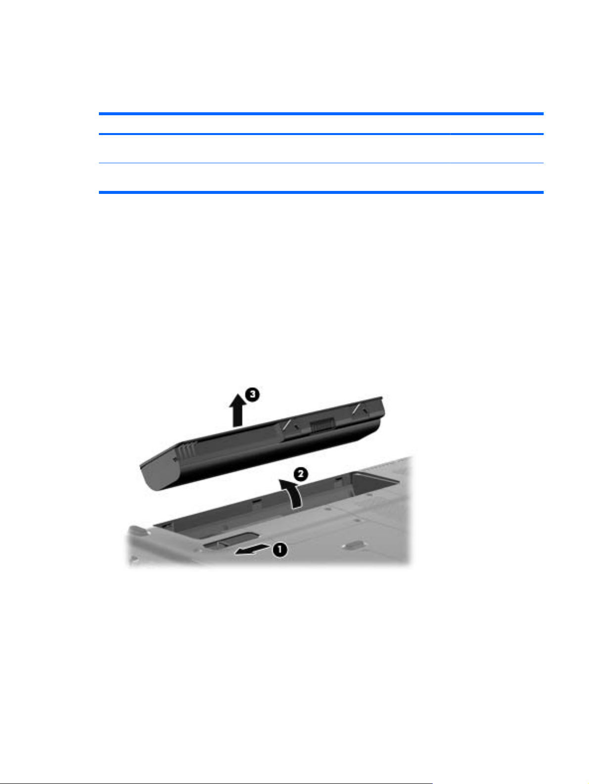
5. Slide the battery release latch (1) to release the battery.
6. Pivot the battery (2) upward and lift it out of the computer (3).
7. Position the computer with the right side toward you.
8. Remove the Phillips PM2.5×6.0 screw (1) that secures the optical drive to the computer.
9. Insert a thin tool, such as a paper clip (2), into the release access. (The optical drive media tray is
partially ejected from the optical drive.)
ENWW Component replacement procedures 5
Page 10

10. Use the media tray frame to remove the optical drive (3).
11. If it is necessary to replace the optical drive bracket, position the optical drive with the optical drive
bracket toward you.
12. Remove the two Phillips PM2.0×3.0 screws (1) that secure the optical drive bracket to the optical
drive.
13. Remove the optical drive bracket (2).
14. Position the computer with the front toward you.
15. Disconnect the two WLAN antenna cables (1) from the WLAN module.
16. Remove the two Phillips PM2.0×3.0 screws (2) that secure the WLAN module to the computer.
(The edge of the module opposite the slot rises away from the computer.)
6 Chapter 1 Removal and replacement procedures ENWW
Page 11

17. Remove the WLAN module (3) by pulling it away from the slot at an angle.
CAUTION: To prevent an unresponsive system, replace the wireless module only with a wireless
module authorized for use in the computer by the governmental agency that regulates wireless
devices in your country or region. If you replace the module and then receive a warning message,
remove the module to restore computer functionality, and then contact technical support through
Help and Support.
NOTE: WLAN modules are designed with a notch (4) to prevent incorrect insertion into the WLAN
module slot.
18. Remove the two Phillips PM2.5×6.0 screws (1) that secure the RTC battery compartment cover to
the computer.
19. Lift the right side of the cover (2), swing it to left, and remove the cover (3). The RTC battery
compartment cover is included in the Plastics Kit, spare part number 486862-001.
20. Disconnect the RTC battery cable (1) from the system board.
ENWW Component replacement procedures 7
Page 12

21. Remove the RTC battery (2).
NOTE: Removing the RTC battery and leaving it uninstalled for 5 or more minutes causes all
passwords and CMOS settings to be cleared.
22. Turn the computer upside down, with the front toward you.
23. Remove the three Phillips PM2.5×17.0 screws that secure the keyboard to the computer.
24. Turn the computer display-side up, with the front toward you.
25. Open the computer as far as possible.
26. Release the top edge of the keyboard by lifting it up to disengage the keyboard from the tabs on
the switch cover.
27. Lift the top edge of the keyboard until it rests at an angle (1).
8 Chapter 1 Removal and replacement procedures ENWW
Page 13

28. Lift the keyboard (2) up until the tabs on the bottom of the keyboard are clear of the switch cover.
29. Release the zero insertion force (ZIF) connector (1) to which the keyboard cable is attached and
disconnect the keyboard cable (2) from the system board.
30. Turn the computer upside down, with the rear toward you.
ENWW Component replacement procedures 9
Page 14

31. Remove the two Phillips PM2.5×10.0 screws (1), the Phillips PM2.0x2.0 broad head screw (2) from
the optical drive bay, and the four Phillips PM2.0x4.0 screws (3) from the battery bay that secure
the switch cover to the computer.
32. Turn the computer display-side up, with the front toward you.
33. Open the computer as far as possible.
34. Release the ZIF connector to which the power button board cable (1) is connected and disconnect
the cable from the system board.
35. Release the ZIF connector to which the volume board cable (2) is connected and disconnect the
cable from the system board.
36. Lift the front edge of the switch cover to disengage it from the computer, pull the switch cover toward
the display until the light pipe on the front of the switch cover clears the top cover, and then lift the
cover up and out of the computer (3).
37. Turn the computer display-side up, with the front toward you.
38. Open the display as far as possible.
10 Chapter 1 Removal and replacement procedures ENWW
Page 15

39. Remove the wireless antenna cables (1) from the hole in the system board and the routing channels
built into the top cover.
40. Disconnect the display panel cable (2).
CAUTION: Support the display assembly when removing the following screws. Failure to support
the display assembly can result in damage to the display assembly and other computer
components.
41. Remove the four black Phillips PM2.5×6.0 screws (1) that secure the display assembly to the
computer.
42. Remove the display assembly (2).
ENWW Component replacement procedures 11
Page 16

43. If it is necessary to replace any of the display assembly internal components, remove the following
screw covers and screws. The display rubber screw covers are included in the Rubber Display Kit,
spare part number 486731-001.
(1) Two rubber screw covers on the display bezel bottom edge
(2) Two Phillips PM2.5×6.0 screws
44. Flex the top side (1), the left and right sides (2), and the bottom (3) of the display bezel until the
bezel disengages from the display enclosure.
45. Remove the display bezel (4). The display bezel is available using spare part number 486733-001
for computers with a camera module, 486739-001 for computers without camera module.
46. If it is necessary to replace the inverter, release the inverter (1) from the clips in the display
enclosure as far as the display panel cable and the backlight cable will allow.
12 Chapter 1 Removal and replacement procedures ENWW
Page 17

47. Disconnect the display panel cable (2) and the backlight cable (3) from the display inverter. The
display inverter is available using spare part number 486736-001.
48. Remove the inverter.
49. If it is necessary to replace the display panel, remove the six black Phillips PM2.5×5.0 screws (1)
that secure the display panel to the display enclosure, and then lift the panel from the enclosure
(2). The display panel is available using the spare part number 483261-001 for computers with
Intel processors, 497182-001 for computers with AMD processors.
50. If it is necessary to replace the display cable, follow these steps:
a. Peel back the plastic that covers the cable (1).
b. Remove the tape that secures the cable to the display (2).
c. Unplug the cable from the display (3).
d. Remove the cable from the display (4).
ENWW Component replacement procedures 13
Page 18

The display cable is available using spare part number 486735-001.
51. If it is necessary to replace the display hinges, remove the four silver Phillips PM2.0×3.0 screws
(1) that secure each hinge to the display.
52. Remove the display hinges (2) from the display. The display hinges are available using spare part
number 486737-001.
53. If it is necessary to replace the wireless antenna transceivers and cables, remove the Phillips
PM2.5×4.0 screw (1) that secures each transceiver to the display enclosure.
54. Detach the wireless antenna transceivers (2) from the display enclosure.
55. Remove the wireless antenna cables from the clips (3) built into the display enclosure.
14 Chapter 1 Removal and replacement procedures ENWW
Page 19

56. Remove the wireless antenna transceivers and cables (4) from the display enclosure. The wireless
antenna transceivers and cables are included in the Wireless Antenna Kit, spare part number
489066-001.
Reverse this procedure to reassemble and install the display assembly.
ENWW Component replacement procedures 15
Page 20

16 Chapter 1 Removal and replacement procedures ENWW
Page 21

2 Recycling
Display
WARNING! The backlight contains mercury. Caution must be exercised when removing and handling
the backlight to avoid damaging this component and causing exposure to the mercury.
CAUTION: The procedures in this appendix can result in damage to display components. The only
components intended for recycling purposes are the liquid crystal display (LCD) panel and the backlight.
Careful handling must be exercised when removing these components.
NOTE: Materials Disposal. This HP product contains mercury in the backlight in the display assembly
that might require special handling at end-of-life. Disposal of mercury may be regulated because of
environmental considerations. For disposal or recycling information, contact your local authorities, or
see the Electronic Industries Alliance (EIA) Web site at
This section provides disassembly instructions for the display assembly. The display assembly must be
disassembled to gain access to the backlight (1) and the liquid crystal display (LCD) panel (2).
http://www.eiae.org.
NOTE: The procedures provided in this appendix are general disassembly instructions. Specific
details, such as screw sizes, quantities, and locations, and component shapes and sizes, can vary from
one computer model to another.
ENWW Display 17
Page 22

Perform the following steps to disassemble the display assembly:
1. Remove all screw covers (1) and screws (2) that secure the display bezel to the display assembly.
2. Lift up and out on the left and right inside edges (1) and the top and bottom inside edges (2) of the
display bezel until the bezel disengages from the display assembly.
3. Remove the display bezel (3).
18 Chapter 2 Recycling ENWW
Page 23

4. Disconnect all display panel cables (1) from the display inverter and remove the inverter (2).
5. Remove all screws (1) that secure the display panel assembly to the display enclosure.
6. Remove the display panel assembly (2) from the display enclosure.
7. Turn the display panel assembly upside down.
8. Remove all screws that secure the display panel frame to the display panel.
9. Use a sharp-edged tool to cut the tape (1) that secures the sides of the display panel to the display
panel frame.
ENWW Display 19
Page 24

10. Remove the display panel frame (2) from the display panel.
11. Remove the screws (1) that secure the backlight cover to the display panel.
12. Lift the top edge of the backlight cover (2) and swing it outward.
13. Remove the backlight cover.
14. Turn the display panel right-side up.
20 Chapter 2 Recycling ENWW
Page 25

15. Remove the backlight cables (1) from the clip (2) in the display panel.
16. Turn the display panel upside down.
17. Remove the backlight frame from the display panel.
WARNING! The backlight contains mercury. Exercise caution when removing and handling the
backlight to avoid damaging this component and causing exposure to the mercury.
18. Remove the backlight from the backlight frame.
ENWW Display 21
Page 26

19. Disconnect the display cable (1) from the LCD panel.
20. Remove the screws (2) that secure the LCD panel to the display rear panel.
21. Release the LCD panel (3) from the display rear panel.
22. Release the tape (4) that secures the LCD panel to the display rear panel.
23. Remove the LCD panel.
24. Recycle the LCD panel and backlight.
22 Chapter 2 Recycling ENWW
Page 27

Index
A
antenna
removal 14
spare part number 15
B
battery
removal 5
spare part numbers 5
bezel
spare part number 12
C
cables, service considerations 3
connectors, service
considerations 3
D
diskette drive
precautions 3
display bezel
spare part number 12
display components
recycling 17
display hinge
removal 14
spare part number 14
display panel
removal 13
spare part number 13
drives
preventing damage 3
DVD/CD-RW Combo Drive
precautions 3
DVD±RW and CD-RW Combo
Drive
precautions 3
E
electrostatic discharge 4
H
hard drive
precautions 3
hinge
removal 14
spare part number 14
I
inverter
removal 12
spare part number 13
O
optical drive
precautions 3
P
plastic parts 2
R
removal/replacement
preliminaries 2
procedures 5
RTC battery compartment cover
removal 7
S
service considerations 2
T
tools required 2
W
wireless antenna
removal 14
spare part number 15
Wireless Antenna Kit, spare part
number 15
ENWW Index 23
Page 28

24 Index ENWW
Page 29

Page 30

 Loading...