

HP Compaq Presario CQ41-204AU, Compaq Presario CQ41-205AX, Compaq Presario CQ41-206AU, Compaq Presario CQ41-206AX, Compaq Presario CQ41-207AX Service Guide
...Page 1

Compaq Presario CQ41 Notebook PC
Maintenance and Service Guide
Document Part Number: 581860-001
September 2009
This guide is a troubleshooting reference used for maintaining and servicing the computer. It provides
comprehensive information on identifying computer features, components, and spare parts; troubleshooting
computer problems; and performing computer disassembly procedures.
Page 2

© Copyright 2009 Hewlett-Packard Development Company, L.P.
AMD Athlon, AMD Sempron, AMD Turion, ATI, and ATI Mobility Radeon are trademarks of Advanced Micro Devices, Inc.
Bluetooth is a trademark owned by its proprietor and used by Hewlett-Packard Company under license. Microsoft and Windows are
U.S. registered trademarks of Microsoft Corporation. SD Logo is a trademark of its
The information contained herein is subject to change without notice. The only warranties for HP products and services are set forth in
the express warranty statements accompanying such products and services. Nothing herein should be construed as constituting an
additional warranty. HP shall not be liable for technical or editorial errors or omissions contained herein.
First Edition: September 2009
Document Part Number: 581860-001
proprietor.
Page 3

Safety warning notice
WARNING: To reduce the possibility of heat-related injuries or of overheating the computer, do not place the computer directly
Å
on your lap or obstruct the computer air vents. Use the computer only on a hard, flat surface. Do not allow another hard surface,
such as an adjoining optional printer, or a soft surface, such as pillows or rugs or clothing, to block airflow. Also, do not allow
the AC adapter to contact the skin or a soft surface, such as pillows or rugs or clothing, during operation. The computer and the
AC adapter comply with the user-accessible surface temperature limits defined by the International Standard for Safety of
Information Technology Equipment (IEC 60950).
Page 4

Contents
1 Product description
2 External component identification
Top components. . . . . . . . . . . . . . . . . . . . . . . . . . . . . . . . . . . . . . . . . . . . . . . . . . . . . . . . . . . . . . . . . . . . . . 2–1
TouchPad . . . . . . . . . . . . . . . . . . . . . . . . . . . . . . . . . . . . . . . . . . . . . . . . . . . . . . . . . . . . . . . . . . . . . . . 2–1
Lights . . . . . . . . . . . . . . . . . . . . . . . . . . . . . . . . . . . . . . . . . . . . . . . . . . . . . . . . . . . . . . . . . . . . . . . . . . 2–2
Buttons and speakers. . . . . . . . . . . . . . . . . . . . . . . . . . . . . . . . . . . . . . . . . . . . . . . . . . . . . . . . . . . . . . . 2–3
Keys . . . . . . . . . . . . . . . . . . . . . . . . . . . . . . . . . . . . . . . . . . . . . . . . . . . . . . . . . . . . . . . . . . . . . . . . . . . 2–4
Display . . . . . . . . . . . . . . . . . . . . . . . . . . . . . . . . . . . . . . . . . . . . . . . . . . . . . . . . . . . . . . . . . . . . . . . . . 2–5
Front components. . . . . . . . . . . . . . . . . . . . . . . . . . . . . . . . . . . . . . . . . . . . . . . . . . . . . . . . . . . . . . . . . . . . . 2–6
Rear component . . . . . . . . . . . . . . . . . . . . . . . . . . . . . . . . . . . . . . . . . . . . . . . . . . . . . . . . . . . . . . . . . . . . . . 2–7
Right-side components. . . . . . . . . . . . . . . . . . . . . . . . . . . . . . . . . . . . . . . . . . . . . . . . . . . . . . . . . . . . . . . . . 2–8
Left-side components . . . . . . . . . . . . . . . . . . . . . . . . . . . . . . . . . . . . . . . . . . . . . . . . . . . . . . . . . . . . . . . . . . 2–9
Bottom components . . . . . . . . . . . . . . . . . . . . . . . . . . . . . . . . . . . . . . . . . . . . . . . . . . . . . . . . . . . . . . . . . . 2–10
Wireless antennas. . . . . . . . . . . . . . . . . . . . . . . . . . . . . . . . . . . . . . . . . . . . . . . . . . . . . . . . . . . . . . . . . . . . 2–11
Additional hardware components . . . . . . . . . . . . . . . . . . . . . . . . . . . . . . . . . . . . . . . . . . . . . . . . . . . . . . . 2–12
3 Illustrated parts catalog
Service tag . . . . . . . . . . . . . . . . . . . . . . . . . . . . . . . . . . . . . . . . . . . . . . . . . . . . . . . . . . . . . . . . . . . . . . . . . . 3–1
Computer major components . . . . . . . . . . . . . . . . . . . . . . . . . . . . . . . . . . . . . . . . . . . . . . . . . . . . . . . . . . . . 3–2
Display assembly . . . . . . . . . . . . . . . . . . . . . . . . . . . . . . . . . . . . . . . . . . . . . . . . . . . . . . . . . . . . . . . . . . . . . 3–8
Plastics Kit . . . . . . . . . . . . . . . . . . . . . . . . . . . . . . . . . . . . . . . . . . . . . . . . . . . . . . . . . . . . . . . . . . . . . . . . . . 3–9
Mass storage devices . . . . . . . . . . . . . . . . . . . . . . . . . . . . . . . . . . . . . . . . . . . . . . . . . . . . . . . . . . . . . . . . . 3–10
Miscellaneous parts . . . . . . . . . . . . . . . . . . . . . . . . . . . . . . . . . . . . . . . . . . . . . . . . . . . . . . . . . . . . . . . . . . 3–11
Sequential part number listing . . . . . . . . . . . . . . . . . . . . . . . . . . . . . . . . . . . . . . . . . . . . . . . . . . . . . . . . . . 3–12
Maintenance and Service Guide iv
Page 5

Contents
4 Removal and replacement procedures
Preliminary replacement requirements . . . . . . . . . . . . . . . . . . . . . . . . . . . . . . . . . . . . . . . . . . . . . . . . . . . . 4–1
Tools required . . . . . . . . . . . . . . . . . . . . . . . . . . . . . . . . . . . . . . . . . . . . . . . . . . . . . . . . . . . . . . . . . . . . 4–1
Service considerations. . . . . . . . . . . . . . . . . . . . . . . . . . . . . . . . . . . . . . . . . . . . . . . . . . . . . . . . . . . . . . 4–1
Plastic parts . . . . . . . . . . . . . . . . . . . . . . . . . . . . . . . . . . . . . . . . . . . . . . . . . . . . . . . . . . . . . . . . . . . . . . 4–1
Grounding guidelines . . . . . . . . . . . . . . . . . . . . . . . . . . . . . . . . . . . . . . . . . . . . . . . . . . . . . . . . . . . . . . 4–2
Component replacement procedures . . . . . . . . . . . . . . . . . . . . . . . . . . . . . . . . . . . . . . . . . . . . . . . . . . . . . . 4–5
Service tag. . . . . . . . . . . . . . . . . . . . . . . . . . . . . . . . . . . . . . . . . . . . . . . . . . . . . . . . . . . . . . . . . . . . . . . 4–5
Computer feet . . . . . . . . . . . . . . . . . . . . . . . . . . . . . . . . . . . . . . . . . . . . . . . . . . . . . . . . . . . . . . . . . . . . 4–6
Battery. . . . . . . . . . . . . . . . . . . . . . . . . . . . . . . . . . . . . . . . . . . . . . . . . . . . . . . . . . . . . . . . . . . . . . . . . . 4–7
Hard drive . . . . . . . . . . . . . . . . . . . . . . . . . . . . . . . . . . . . . . . . . . . . . . . . . . . . . . . . . . . . . . . . . . . . . . . 4–8
Memory module . . . . . . . . . . . . . . . . . . . . . . . . . . . . . . . . . . . . . . . . . . . . . . . . . . . . . . . . . . . . . . . . . 4–10
RTC battery. . . . . . . . . . . . . . . . . . . . . . . . . . . . . . . . . . . . . . . . . . . . . . . . . . . . . . . . . . . . . . . . . . . . . 4–12
WLAN module . . . . . . . . . . . . . . . . . . . . . . . . . . . . . . . . . . . . . . . . . . . . . . . . . . . . . . . . . . . . . . . . . . 4–14
Optical drive . . . . . . . . . . . . . . . . . . . . . . . . . . . . . . . . . . . . . . . . . . . . . . . . . . . . . . . . . . . . . . . . . . . . 4–20
Keyboard. . . . . . . . . . . . . . . . . . . . . . . . . . . . . . . . . . . . . . . . . . . . . . . . . . . . . . . . . . . . . . . . . . . . . . . 4–21
Keyboard cover . . . . . . . . . . . . . . . . . . . . . . . . . . . . . . . . . . . . . . . . . . . . . . . . . . . . . . . . . . . . . . . . . . 4–24
Speaker assembly . . . . . . . . . . . . . . . . . . . . . . . . . . . . . . . . . . . . . . . . . . . . . . . . . . . . . . . . . . . . . . . . 4–26
Display assembly . . . . . . . . . . . . . . . . . . . . . . . . . . . . . . . . . . . . . . . . . . . . . . . . . . . . . . . . . . . . . . . . 4–28
Webcam/microphone module (select models only) . . . . . . . . . . . . . . . . . . . . . . . . . . . . . . . . . . . . . . 4–34
Microphone module . . . . . . . . . . . . . . . . . . . . . . . . . . . . . . . . . . . . . . . . . . . . . . . . . . . . . . . . . . . . . . 4–35
Top cover . . . . . . . . . . . . . . . . . . . . . . . . . . . . . . . . . . . . . . . . . . . . . . . . . . . . . . . . . . . . . . . . . . . . . . 4–36
Bluetooth module and cable (select models only) . . . . . . . . . . . . . . . . . . . . . . . . . . . . . . . . . . . . . . . 4–38
Modem module . . . . . . . . . . . . . . . . . . . . . . . . . . . . . . . . . . . . . . . . . . . . . . . . . . . . . . . . . . . . . . . . . . 4–40
Audio board. . . . . . . . . . . . . . . . . . . . . . . . . . . . . . . . . . . . . . . . . . . . . . . . . . . . . . . . . . . . . . . . . . . . . 4–42
USB board. . . . . . . . . . . . . . . . . . . . . . . . . . . . . . . . . . . . . . . . . . . . . . . . . . . . . . . . . . . . . . . . . . . . . . 4–44
Power connector and cable . . . . . . . . . . . . . . . . . . . . . . . . . . . . . . . . . . . . . . . . . . . . . . . . . . .
System board. . . . . . . . . . . . . . . . . . . . . . . . . . . . . . . . . . . . . . . . . . . . . . . . . . . . . . . . . . . . . . . . . . . . 4–48
Fan/heat sink assembly or heat sink . . . . . . . . . . . . . . . . . . . . . . . . . . . . . . . . . . . . . . . . . . . . . . . . . . 4–52
Fan (for models with UMA graphics subsystems) . . . . . . . . . . . . . . . . . . . . . . . . . . . . . . . . . . . . . . . 4–56
Processor . . . . . . . . . . . . . . . . . . . . . . . . . . . . . . . . . . . . . . . . . . . . . . . . . . . . . . . . . . . . . . . . . . . . . . . 4–57
. . . . . . 4–46
v Maintenance and Service Guide
Page 6

5 Setup Utility
Starting Setup Utility . . . . . . . . . . . . . . . . . . . . . . . . . . . . . . . . . . . . . . . . . . . . . . . . . . . . . . . . . . . . . . . . . . 5–1
Using Setup Utility. . . . . . . . . . . . . . . . . . . . . . . . . . . . . . . . . . . . . . . . . . . . . . . . . . . . . . . . . . . . . . . . . . . . 5–1
Changing the language of Setup Utility . . . . . . . . . . . . . . . . . . . . . . . . . . . . . . . . . . . . . . . . . . . . . . . . 5–1
Navigating and selecting in Setup Utility . . . . . . . . . . . . . . . . . . . . . . . . . . . . . . . . . . . . . . . . . . . . . . . 5–2
Displaying system information . . . . . . . . . . . . . . . . . . . . . . . . . . . . . . . . . . . . . . . . . . . . . . . . . . . . . . . 5–2
Restoring default settings in Setup Utility . . . . . . . . . . . . . . . . . . . . . . . . . . . . . . . . . . . . . . . . . . . . . . 5–2
Exiting Setup Utility . . . . . . . . . . . . . . . . . . . . . . . . . . . . . . . . . . . . . . . . . . . . . . . . . . . . . . . . . . . . . . . 5–3
Setup Utility menus . . . . . . . . . . . . . . . . . . . . . . . . . . . . . . . . . . . . . . . . . . . . . . . . . . . . . . . . . . . . . . . . . . . 5–3
Main menu . . . . . . . . . . . . . . . . . . . . . . . . . . . . . . . . . . . . . . . . . . . . . . . . . . . . . . . . . . . . . . . . . . . . . . 5–3
Security menu . . . . . . . . . . . . . . . . . . . . . . . . . . . . . . . . . . . . . . . . . . . . . . . . . . . . . . . . . . . . . . . . . . . . 5–3
System Configuration menu . . . . . . . . . . . . . . . . . . . . . . . . . . . . . . . . . . . . . . . . . . . . . . . . . . . . . . . . . 5–4
Diagnostics menu . . . . . . . . . . . . . . . . . . . . . . . . . . . . . . . . . . . . . . . . . . . . . . . . . . . . . . . . . . . . . . . . . 5–4
6 Specifications
Computer specifications. . . . . . . . . . . . . . . . . . . . . . . . . . . . . . . . . . . . . . . . . . . . . . . . . . . . . . . . . . . . . . . . 6–1
14.1-inch display specifications. . . . . . . . . . . . . . . . . . . . . . . . . . . . . . . . . . . . . . . . . . . . . . . . . . . . . . . . . . 6–2
Hard drive specifications . . . . . . . . . . . . . . . . . . . . . . . . . . . . . . . . . . . . . . . . . . . . . . . . . . . . . . . . . . . . . . . 6–3
Blu-ray ROM with LightScribe DVD±R/RW SuperMulti Double-Layer Drive specifications . . . . . . . . . 6–4
DVD±RW and CD-RW SuperMulti Double-Layer Combo Drive with LightScribe specifications. . . . . . 6–5
System DMA specifications. . . . . . . . . . . . . . . . . . . . . . . . . . . . . . . . . . . . . . . . . . . . . . . . . . . . . . . . . . . . . 6–6
System memory map specifications (for models with discrete graphics subsystems). . . . . . . . . . . . . . . . . 6–6
System memory map specifications (for models with UMA graphics subsystems) . . . . . . . . . . . . . . . . . . 6–8
System interrupt specifications (for models with discrete graphics subsystems) . . . . . . . . . . . . . . . . . . . . 6–9
System interrupt specifications (for models with UMA graphics subsystems) . . . . . . . . . . . . . . . . . . . . . 6–10
System I/O address specifications (for models with discrete graphics subsystems) . . . . . . . . . . . . . . . . . 6–11
System I/O address specification (for models with UMA graphics subsystems) . . . . . . . . . . . . . . . . . . . 6–13
Contents
7 Screw listing
Phillips PM2.0×3.0 broadhead screw . . . . . . . . . . . . . . . . . . . . . . . . . . . . . . . . . . . . . . . . . . . . . . . . . . . . . 7–1
Phillips PM2.0×3.0 screw . . . . . . . . . . . . . . . . . . . . . . . . . . . . . . . . . . . . . . . . . . . . . . . . . . . . . . . . . . . . . . 7–2
Phillips PM2.0×4.0 screw . . . . . . . . . . . . . . . . . . . . . . . . . . . . . . . . . . . . . . . . . . . . . . . . . . . . . . . . . . . . . . 7–4
Phillips PM2.0×10.0 captive screw . . . . . . . . . . . . . . . . . . . . . . . . . . . . . . . . . . . . . . . . . . . . . . . . . . . . . . . 7–6
Phillips PM2.5×3.0 screw . . . . . . . . . . . . . . . . . . . . . . . . . . . . . . . . . . . . . . . . . . . . . . . . . . . . . . . . . . . . . . 7–7
Phillips PM2.5×4.0 screw . . . . . . . . . . . . . . . . . . . . . . . . . . . . . . . . . . . . . . . . . . . . . . . . . . . . . . . . . . . . . . 7–9
Phillips PM2.5×5.0 screw . . . . . . . . . . . . . . . . . . . . . . . . . . . . . . . . . . . . . . . . . . . . . . . . . . . . . . . . . . . . . 7–10
Phillips PM2.5×5.0 captive screw . . . . . . . . . . . . . . . . . . . . . . . . . . . . . . . . . . . . . . . . . . . . . . . . . . . . . . . 7–14
Phillips PM2.5×6.0 screw . . . . . . . . . . . . . . . . . . . . . . . . . . . . . . . . . . . . . . . . . . . . . . . . . . . . . . . . . . . . . 7–15
Phillips PM2.5×7.0 captive screw . . . . . . . . . . . . . . . . . . . . . . . . . . . . . . . . . . . . . . . . . . . . . . . . . . . . . . . 7–17
Phillips PM2.5×10.0 screw . . . . . . . . . . . . . . . . . . . . . . . . . . . . . . . . . . . . . . . . . . . . . . . . . . . . . . . . . . . . 7–18
Phillips PM2.5×17.0 screw . . . . . . . . . . . . . . . . . . . . . . . . . . . . . . . . . . . . . . . . . . . . . . . . . . . . . . . . . . . . 7–19
Phillips PM3.0×3.0 screw . . . . . . . . . . . . . . . . . . . . . . . . . . . . . . . . . . . . . . . . . . . . . . . . . . . . . . . . . . . . . 7–20
Maintenance and Service Guide vi
Page 7

Contents
8 Backup and recovery
Overview . . . . . . . . . . . . . . . . . . . . . . . . . . . . . . . . . . . . . . . . . . . . . . . . . . . . . . . . . . . . . . . . . . . . . . . . . . . 8–1
Creating recovery discs . . . . . . . . . . . . . . . . . . . . . . . . . . . . . . . . . . . . . . . . . . . . . . . . . . . . . . . . . . . . . . . . 8–2
Backing up your information . . . . . . . . . . . . . . . . . . . . . . . . . . . . . . . . . . . . . . . . . . . . . . . . . . . . . . . . . . . . 8–3
Using Windows Backup and Restore . . . . . . . . . . . . . . . . . . . . . . . . . . . . . . . . . . . . . . . . . . . . . . . . . . 8–4
Using system restore points . . . . . . . . . . . . . . . . . . . . . . . . . . . . . . . . . . . . . . . . . . . . . . . . . . . . . . . . . 8–4
Performing a recovery . . . . . . . . . . . . . . . . . . . . . . . . . . . . . . . . . . . . . . . . . . . . . . . . . . . . . . . . . . . . . . . . . 8–5
Recovering from the recovery discs . . . . . . . . . . . . . . . . . . . . . . . . . . . . . . . . . . . . . . . . . . . . . . . . . . . 8–6
Recovering from the dedicated recovery partition (select models only) . . . . . . . . . . . . . . . . . . . . . . . 8–6
9 Connector pin assignments
Audio-in (microphone). . . . . . . . . . . . . . . . . . . . . . . . . . . . . . . . . . . . . . . . . . . . . . . . . . . . . . . . . . . . . . . . . 9–1
Audio-out (headphone) . . . . . . . . . . . . . . . . . . . . . . . . . . . . . . . . . . . . . . . . . . . . . . . . . . . . . . . . . . . . . . . . 9–1
External monitor. . . . . . . . . . . . . . . . . . . . . . . . . . . . . . . . . . . . . . . . . . . . . . . . . . . . . . . . . . . . . . . . . . . . . . 9–2
HDMI . . . . . . . . . . . . . . . . . . . . . . . . . . . . . . . . . . . . . . . . . . . . . . . . . . . . . . . . . . . . . . . . . . . . . . . . . . . . . . 9–3
RJ-11 (modem) (select models only) . . . . . . . . . . . . . . . . . . . . . . . . . . . . . . . . . . . . . . . . . . . . . . . . . . . . . . 9–4
RJ-45 (network) . . . . . . . . . . . . . . . . . . . . . . . . . . . . . . . . . . . . . . . . . . . . . . . . . . . . . . . . . . . . . . . . . . . . . . 9–5
Universal Serial Bus. . . . . . . . . . . . . . . . . . . . . . . . . . . . . . . . . . . . . . . . . . . . . . . . . . . . . . . . . . . . . . . . . . . 9–6
10Power cord set requirements
Requirements for all countries and regions . . . . . . . . . . . . . . . . . . . . . . . . . . . . . . . . . . . . . . . . . . . . . . . . 10–1
Requirements for specific countries and regions . . . . . . . . . . . . . . . . . . . . . . . . . . . . . . . . . . . . . . . . . . . . 10–2
11Recycling
Battery . . . . . . . . . . . . . . . . . . . . . . . . . . . . . . . . . . . . . . . . . . . . . . . . . . . . . . . . . . . . . . . . . . . . . . . . . . . . 11–1
Display . . . . . . . . . . . . . . . . . . . . . . . . . . . . . . . . . . . . . . . . . . . . . . . . . . . . . . . . . . . . . . . . . . . . . . . . . . . . 11–1
Index
vii Maintenance and Service Guide
Page 8

Product description
Discrete graphics
Category Description
Product Name Compaq Presario CQ41 Notebook PC 9 9
subsystem memory
UMA graphics
subsystem memory
1
Processors AMD Turion™ Ultra Dual-Core M600 (2.4-GHz,
2-MB L2 cache, 3.6
AMD Turion Dual-Core M520 (2.3-GHz, 1-MB L2
cache, 3.6
AMD Turion Dual-Core M500 (2.2-GHz, 1-MB L2
cache, 3.6
AMD Athlon™ X2 Dual-Core M320 (2.1-GHz, 1-MB
L2 cache, 3.2
AMD Athlon X2 Dual-Core M300 (2.0-GHz, 1-MB L2
cache, 3.2
AMD Sempron™ X2 Single-Core M100 (2.0-GHz,
512-KB L2 cache, 3.2
Chipset AT I™ RX881 9
ATI RS880M 9
Southbridge: AMD SB710 9 9
Graphics ATI Mobility Radeon™ HD 4330 discrete graphics
processor with 512 MB of dedicated video memory
ATI Mobility Radeon 4200 unified memory
architecture (UMA, integrated) with shared video
memory:
■ Up to 510 MB of video memory on computer
models equipped with 1 GB of main system
memory
■ Up to 958 MB of video memory on computer
models equipped with 2 GB of main system
memory (32-bit OS)
■ Up to 958 MB of video memory on computer
models equipped with 2 GB of main system
memory (64-bit OS)
GT/s HyperTransport speed)
GT/s HyperTransport speed)
GT/s HyperTransport speed)
GT/s HyperTransport speed)
GT/s HyperTransport speed)
GT/s HyperTransport speed)
9 9
9 9
9 9
9 9
9 9
9 9
9
9
9
Panel 14.1-in WXGA BrightView (1280 × 800) display
panel
16:10 wide aspect ratio
Maintenance and Service Guide 1–1
9 9
(Continued)
Page 9

Product description
Category Description
Memory 2 customer-accessible/upgradable memory module
slots
Supports dual-channel memory
Supports up to 8 GB of system RAM,
PC2-6400, 800-MHz, DDR2
Supports the following configurations:
■ 4096-MB total system memory
× 2, dual-channel)
(2048
■ 3072-MB total system memory (2048 + 1024)
■ 2048-MB total system memory
× 2, dual-channel)
(1024
■ 2048-MB total system memory (2048 × 1)
■ 1024-MB total system memory (1024 × 1)
Hard drive Supports a 9.50-mm, 6.35-cm (2.50-in) hard drive
Customer-accessible
Serial ATA
Supports the following hard drives:
■ 500-GB, 5400-rpm
■ 320-GB, 7200- and 5400-rpm
■ 250-GB, 7200- and 5400-rpm
■ 160-GB, 7200- and 5400-rpm
Discrete graphics
subsystem memory
9 9
9 9
UMA graphics
subsystem memory
Optical drive 12.7-mm tray load
Serial ATA (SATA)
Fixed (removal of 1 screw required)
Customer-accessible
Parallel ATA
Supports no-optical-drive option
Supports the following drives:
■ DVD±RW and CD-RW SuperMulti Double-Layer
Combo Drive with LightScribe
■ Blu-ray ROM with LightScribe DVD±R/RW
SuperMulti Double-Layer Drive
Microphone Single analog microphone 9 9
Audio High-definition audio
Supports Microsoft® premium requirements
Presario-branded Altec Lansing speakers
Modem (select
models only)
Webcam (select
models only)
Ethernet Integrated 10/100 network interface card (NIC) 9
56K MDC V.92 data/fax modem (select models only) 9 9
VGA webcam
Fixed (no tilt)
Activity LED
640 × 480, 24 frames per second
9 9
9 9
9 9
(Continued)
1–2 Maintenance and Service Guide
Page 10

Product description
Category Description
Wireless Integrated WLAN options by way of wireless module
2 wireless antennas built into display assembly
Supports no-WLAN option
Support for the following WLAN formats:
■ Broadcom BCM4322 802.11a/b/g/n 2x2 WLAN
module
■ Broadcom BCM4312 802.11b/g WLAN module
■ Atheros AR5009 802.11a/b/g/n WLAN module
■ Atheros AR9285 802.11b/g/n WLAN module
■ Broadcom BCM2070 Bluetooth® 2.1 module
(select models only)
External media
cards
Ports Audio-in (stereo microphone)
Keyboard/pointing
devices
Digital Media Slot supporting Memory Stick (MS),
Memory Stick Pro (MSP), MultiMediaCard (MMC),
Secure Digital (SD) Memory Card, and xD-Picture
Card (XD). Adapter (purchased separately) provides
support for mini versions of SD, MMC, and MS
Audio-out (stereo headphone)
RJ-11 modem (select models only)
HDMI v. 1.3b supporting 1080p with HDCP key
HP Smart Adapter power
RJ-45 network (Ethernet, includes link and
lights)
activity
USB 2.0
VGA (Dsub 15-pin) supports the following
resolutions:
■ 1920 × 1200 external resolution at 60 GHz
■ 1600 × 1200 external resolution at 75 GHz
hot plug/unplug with auto-detect
14.1-inch keyboard
TouchPad with 2 TouchPad buttons
Supports 2-way scroll
Taps enabled as default
Duo
Discrete graphics
subsystem memory
9 9
9 9
9 9
9 9
UMA graphics
subsystem memory
Power requirements 90-W HP Smart Adapter with localized cable
support (3-wire plug with ground pin, supports
plug
3-pin DC connector)
65-W HP Smart Adapter with localized cable
support (3-wire plug with ground pin, supports
plug
3-pin DC connector)
Battery option:
6-cell, 2.20-Ah (47-Wh) Li-ion battery
9
9
9 9
(Continued)
Maintenance and Service Guide 1–3
Page 11

Product description
Discrete graphics
Category Description
Security Kensington Security Lock 9 9
Operating system Preinstalled:
■ Windows® 7 Professional (32-bit)
■ Windows 7 Premium (32-bit)
■ Windows 7 Basic (32-bit)
■ FreeDOS
■ RedFlag
Serviceability End-user replaceable parts:
■ AC adapter
■ Battery (system)
■ Hard drive
■ Memory modules
■ RTC battery
■ Optical drive
■ WLAN module
subsystem memory
9 9
9 9
UMA graphics
subsystem memory
1–4 Maintenance and Service Guide
Page 12
Top components
TouchPad
2
External component identification
Item Component Description
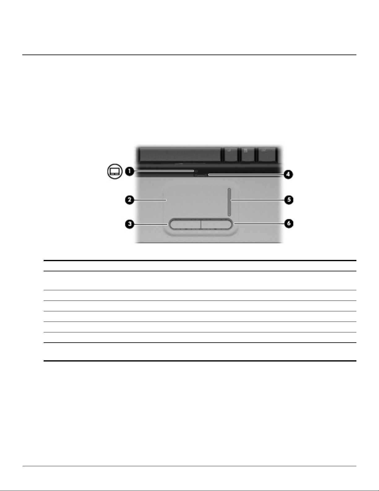
(1) TouchPad light ■ White: TouchPad is enabled.
■ Amber: TouchPad is disabled.
(2) TouchPad* Moves the pointer and selects or activates items on the screen.
(3) Left TouchPad button* Functions like the left button on an external mouse.
(4) TouchPad on/off button Enables/disables the TouchPad.
(5) TouchPad scroll zone Scrolls up or down.
(6) Right TouchPad button* Functions like the right button on an external mouse.
*This table describes factory settings. To view or change pointing device preferences, select Start > Devices and Printers.
Then, right-click the device representing your computer, and select Mouse settings.
Maintenance and Service Guide 2–1
Page 13
External component identification
Lights
Item Component Description
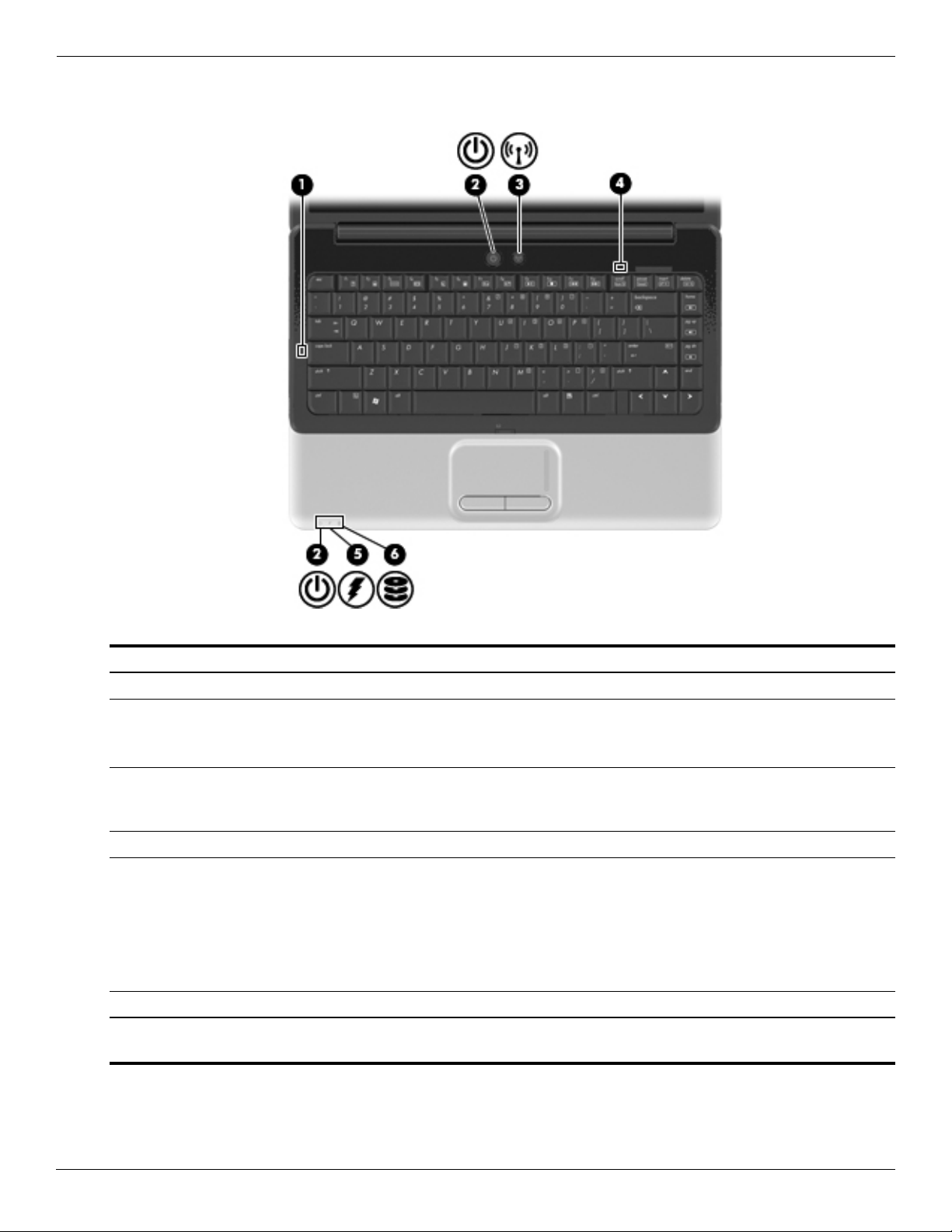
(1) Caps lock light On: Caps lock is on.
(2) Power lights (2)* ■ On: The computer is on.
■ Blinking: The computer is in the Sleep state.
■ Off: The computer is off or in Hibernation.
(3) Wireless light ■ Blue: An integrated wireless device, such as a wireless local area network
(WLAN) device and/or a Bluetooth device, is on.
■ Amber: All wireless devices are off.
(4) Num lock light On: Num lock is on or the embedded numeric keypad is enabled.
(5) Battery light ■ On: A battery is charging.
■ Blinking: A battery that is the only available power source has reached a
low battery level or a critical battery level.
■ Off: If the computer is plugged into an external power source, the light is
turned off when all batteries in the computer are fully charged. If the
computer is not plugged into an external power source, the light stays off
until the battery reaches a low battery level.
(6) Drive light Blinking: The hard drive or optical drive is being accessed.
*The 2 power lights display the same information. The light on the power button is visible only when the computer is open. The
power light on the front of the computer is visible whether the computer is open or closed.
2–2 Maintenance and Service Guide
Page 14
Buttons and speakers
External component identification
Item Component Description
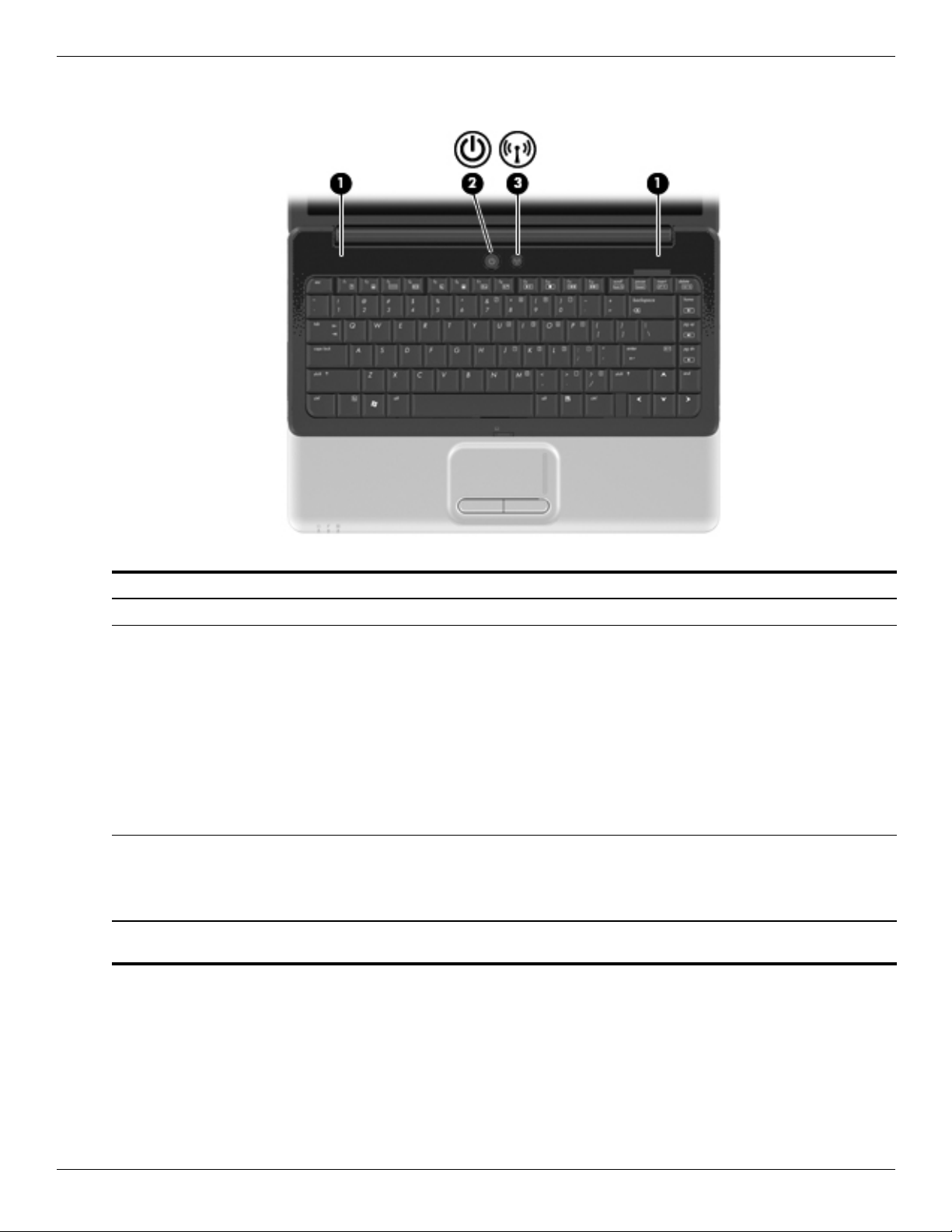
(1) Speakers (2) ■ Produce sound.
(2) Power button* ■ When the computer is off, press the button to turn on the computer.
■ When the computer is on, briefly press the button to initiate Sleep.
■ When the computer is in the Sleep state, briefly press the button to
Sleep.
exit
■ When the computer is in Hibernation, briefly press the button to
Hibernation.
exit
If the computer has stopped responding and Windows® shutdown
procedures are ineffective, press and hold the power button for at least
seconds to turn off the computer.
5
To learn more about your power settings, select Start > Control Panel >
System and Security > Power Options.
(3) Wireless button Turns the wireless feature on or off but does not create a wireless
connection.
A wireless network must be set up in order to establish a wireless
✎
connection.
*This table describes factory settings. For information about changing factory settings, refer to the user guides located in
and Support.
Help
Maintenance and Service Guide 2–3
Page 15
External component identification
Keys
Item Component Description
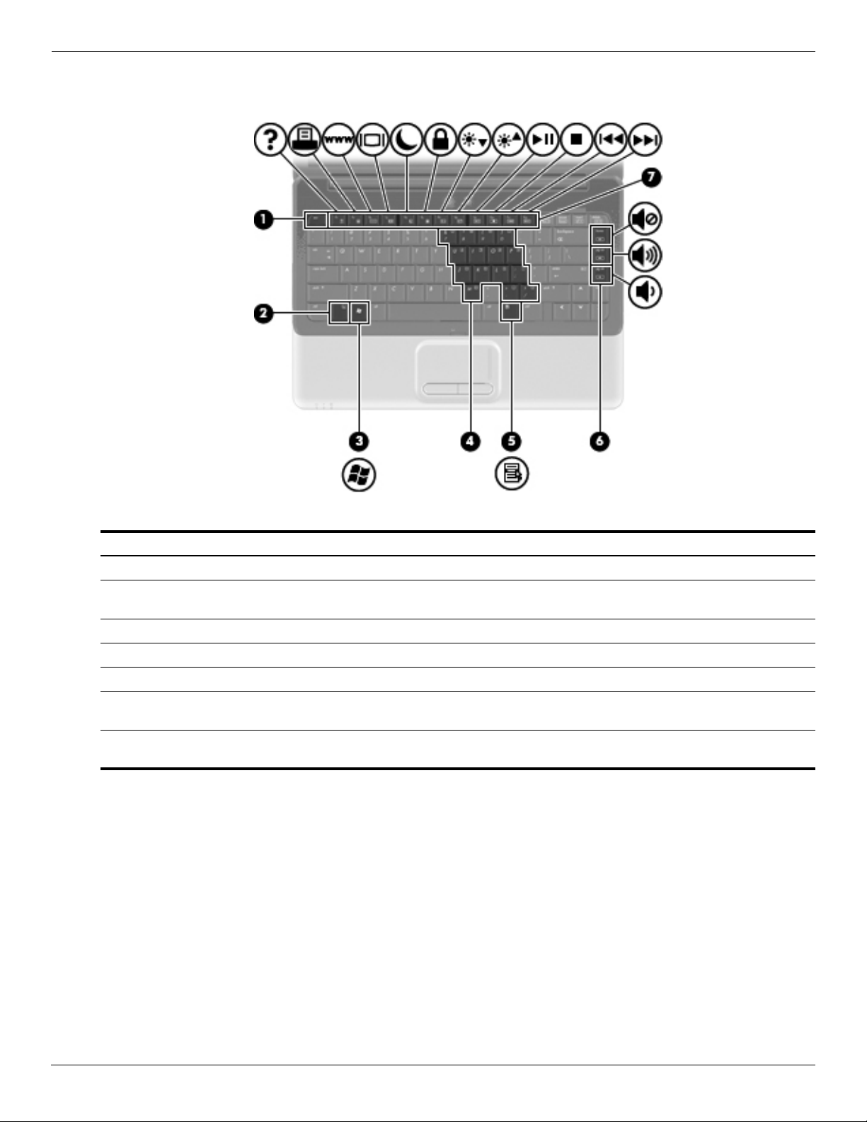
(1) esc key Displays system information when pressed in combination with the fn key.
(2) fn key Executes frequently used system functions when pressed in combination with
a function key or the esc key.
(3) Windows logo key Displays the Windows Start menu.
(4) Embedded numeric keypad keys Can be used like the keys on an external numeric keypad.
(5) Windows applications key Displays a shortcut menu for items beneath the pointer.
(6) Navigation keys (home, pg up,
down)
pg
(7) Function keys Execute frequently used system functions when pressed in combination with
Execute volume mute, volume up, or volume down when pressed in
combination with the fn key.
the fn key.
2–4 Maintenance and Service Guide
Page 16
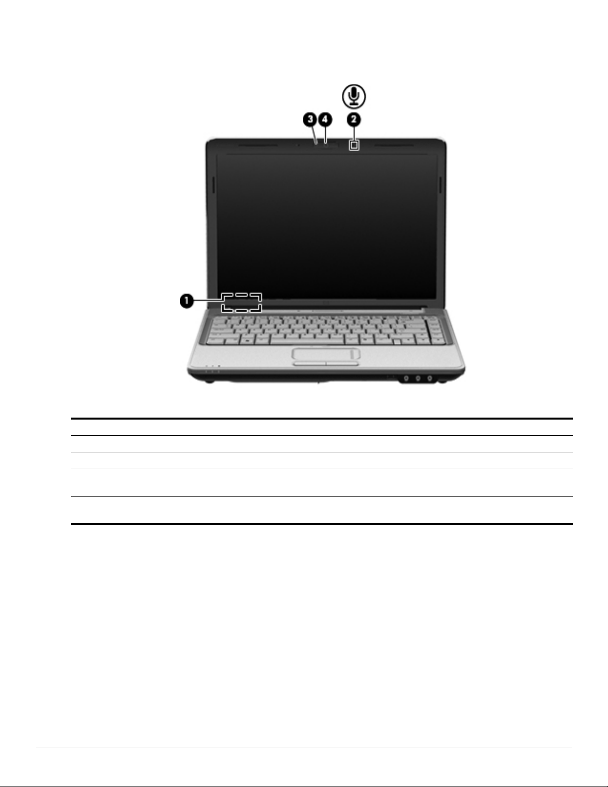
Display
External component identification
Item Component Description
(1) Internal display switch Turns off the display if the display is closed while the computer is turned on.
(2) Internal microphone Records sound.
(3) Integrated webcam light
(select models only)
(4) Integrated webcam
(select models only)
On: The integrated webcam is in use.
Records video and captures still photographs.
Maintenance and Service Guide 2–5
Page 17
External component identification
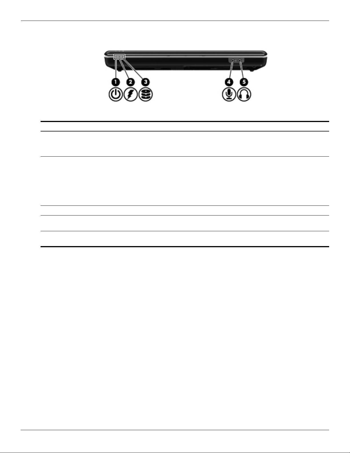
Front components
Item Component Description
(1) Power l ig ht ■ On: The computer is on.
(2) Battery light ■ On: A battery is charging.
■ Blinking: The computer is in the Sleep state.
■ Off: The computer is off or in Hibernation.
■ Blinking: A battery that is the only available power source has reached a
low battery level or a critical battery level.
■ Off: If the computer is plugged into an external power source, the light is
turned off when all batteries in the computer are fully charged. If the
computer is not plugged into an external power source, the light stays off
until the battery reaches a low battery level.
(3) Drive light Blinking: The hard drive or optical drive is being accessed.
(4) Audio-in (microphone) jack Connects an optional computer headset microphone, stereo array
microphone, or monaural microphone.
(5) Audio-out (headphone) jack Produces sound when connected to optional powered stereo speakers,
headphones, ear buds, a headset, or television audio.
2–6 Maintenance and Service Guide
Page 18
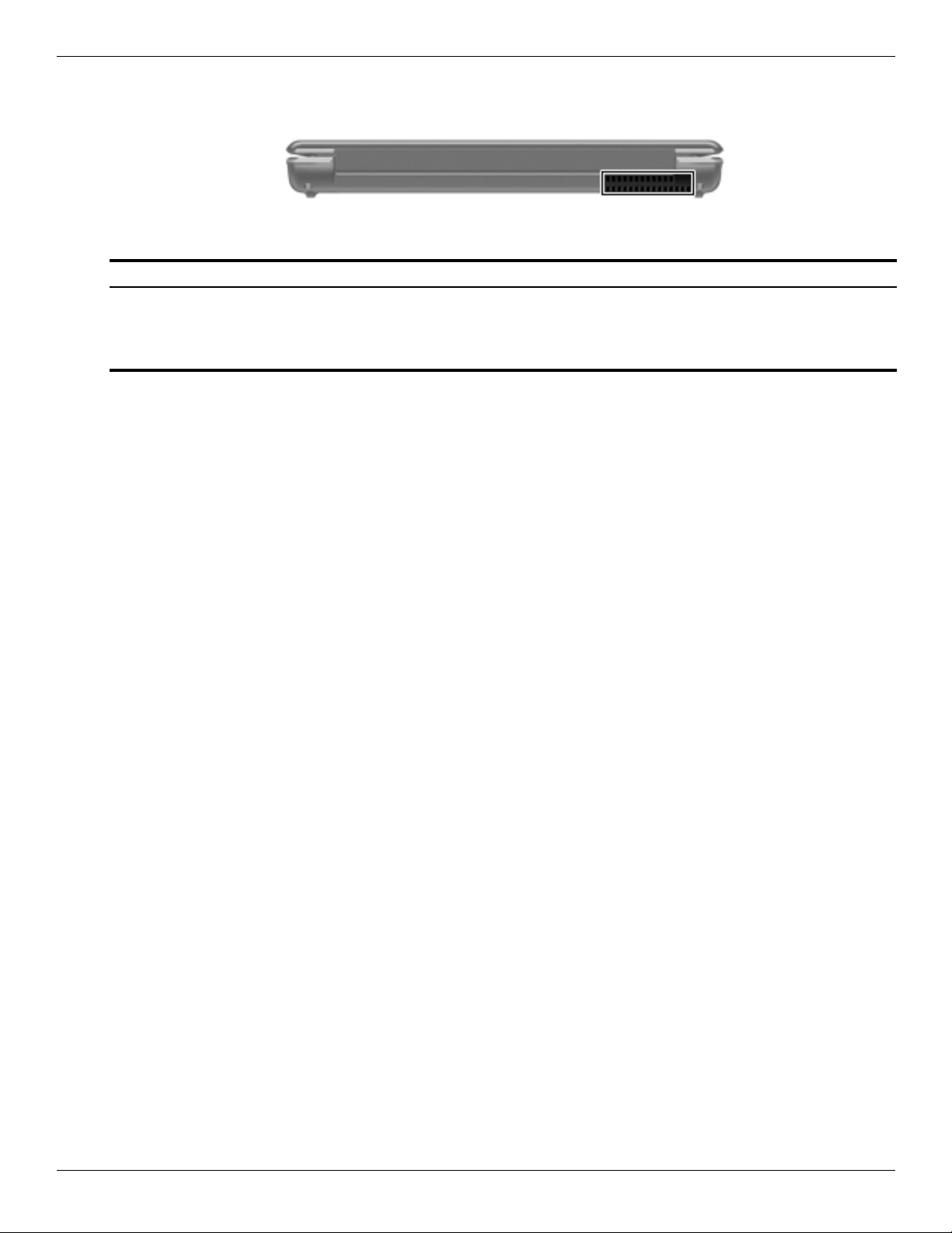
Rear component
Component Description
Vent Enables airflow to cool internal components.
External component identification
The computer fan starts up automatically to cool internal components
✎
and prevent overheating. It is normal for the internal fan to cycle on and
off during routine operation.
Maintenance and Service Guide 2–7
Page 19
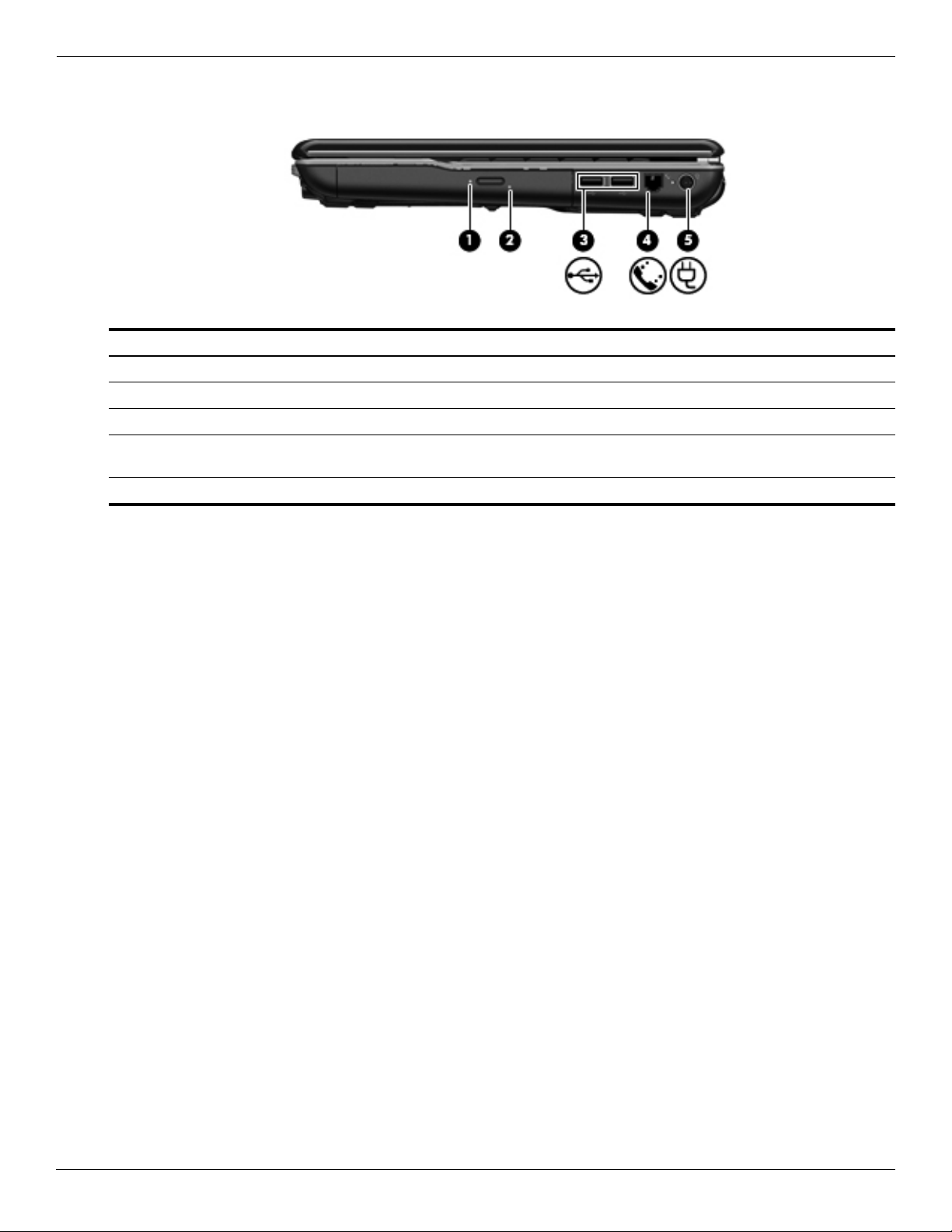
External component identification
Right-side components
Item Component Description
(1) Optical drive light Blinking: The optical drive is being accessed.
(2) Optical drive Reads and writes to optical discs.
(3) USB ports (2) Connect optional USB devices.
(4) RJ-11 (modem) jack
(select models only)
(5) Power connector Connects an AC adapter.
Connects a modem cable.
2–8 Maintenance and Service Guide
Page 20
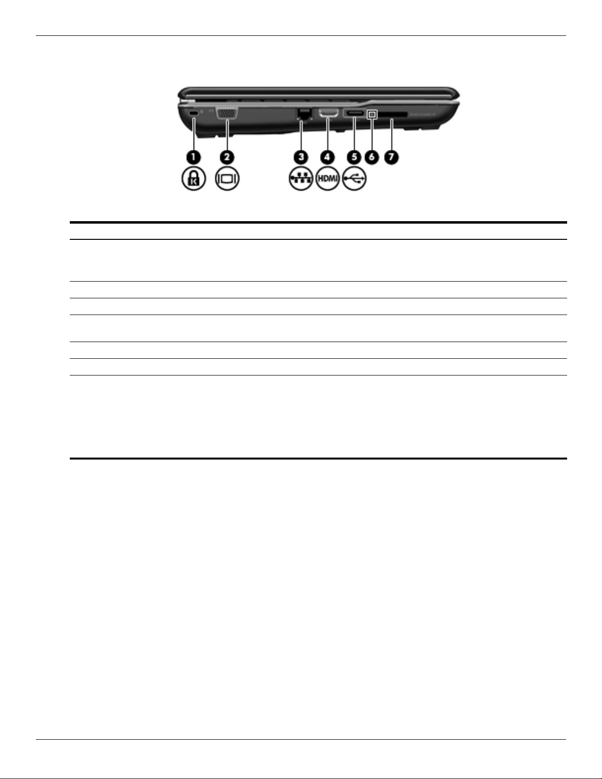
Left-side components
Item Component Description
(1) Security cable slot Attaches an optional security cable to the computer.
(2) External monitor port Connects an external VGA monitor or projector.
(3) RJ-45 (network) jack Connects a network cable.
(4) HDMI port Connects an optional video or audio device, such as a high-definition
External component identification
The security cable is designed to act as a deterrent, but it may not
✎
prevent the computer from being mishandled or stolen.
television, or any compatible digital or audio component.
(5) USB port Connects an optional USB device.
(6) Digital Media Slot light On: A digital card is being accessed.
(7) Digital Media Slot Supports the following optional digital card formats:
■ Memory Stick (MS)
■ Memory Stick Pro (MSP)
■ MultiMediaCard (MMC)
■ Secure Digital (SD) Memory Card
■ xD-Picture Card (XD)
Maintenance and Service Guide 2–9
Page 21
External component identification
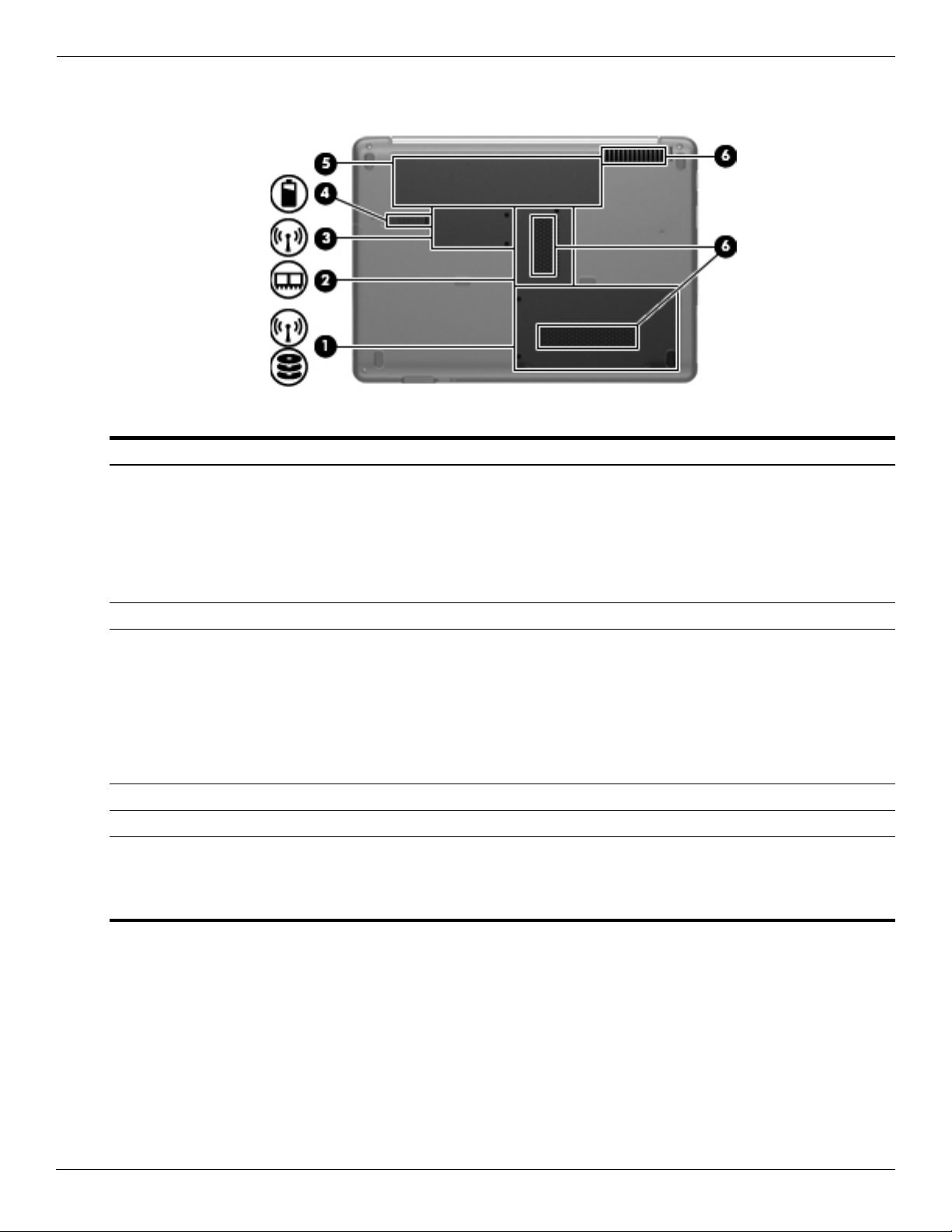
Bottom components
Item Component Description
(1) Hard drive bay Holds the hard drive and, on select models, the wireless LAN (WLAN) device.
To prevent an unresponsive system, replace the wireless module only
Ä
with a wireless module authorized for use in the computer by the
governmental agency that regulates wireless devices in your country or
region. If you replace the module and then receive a warning message,
remove the module to restore computer functionality, and then contact
technical support through Help and Support.
(2) Memory module compartment Contains the 2 memory module slots.
(3) Mini Card compartment Holds the real-time clock (RTC) battery and, on select models, the WLAN
device.
To prevent an unresponsive system, replace the wireless module only
Ä
with a wireless module authorized for use in the computer by the
governmental agency that regulates wireless devices in your country or
region. If you replace the module and then receive a warning message,
remove the module to restore computer functionality, and then contact
technical support through Help and Support.
(4) Battery release latch Releases the battery from the battery bay.
(5) Battery bay Holds the battery.
(6) Vents (3) Enable airflow to cool internal components.
The computer fan starts up automatically to cool internal components
✎
and prevent overheating. It is normal for the internal fan to cycle on and
off during routine operation.
2–10 Maintenance and Service Guide
Page 22
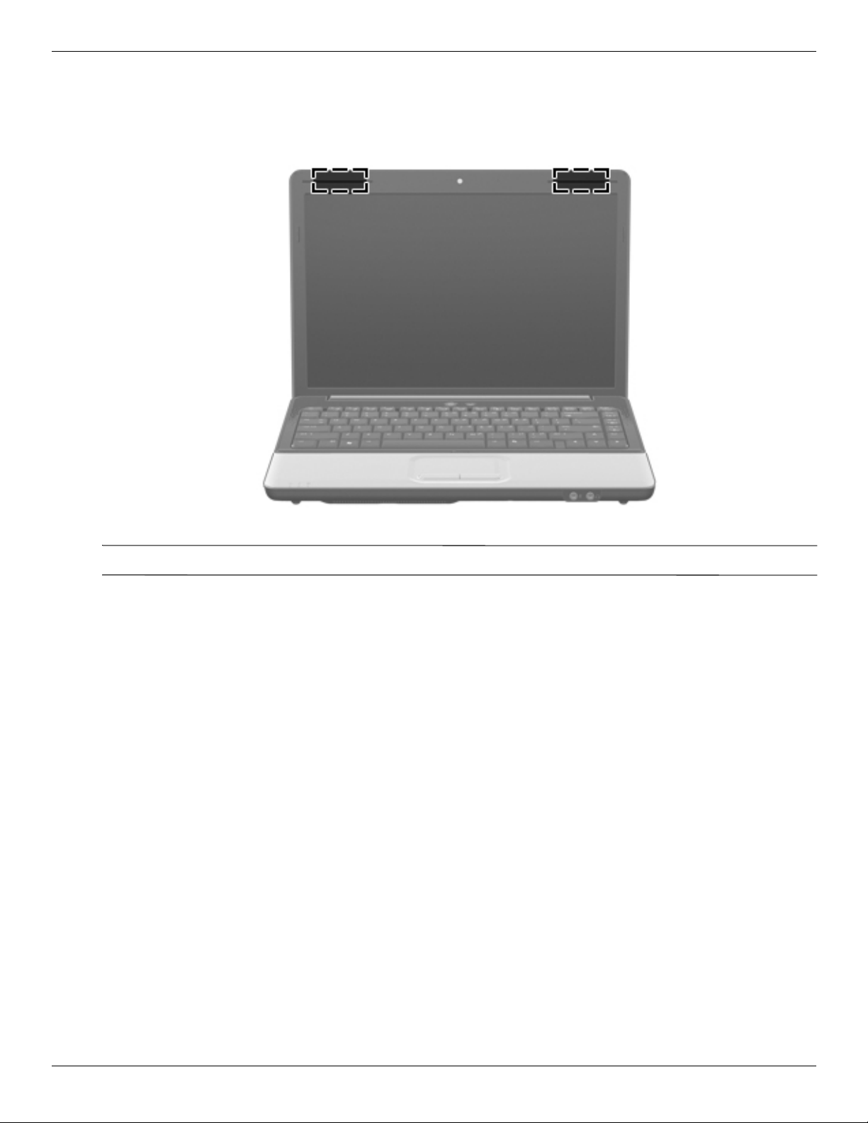
Wireless antennas
Two antennas send and receive signals from one or more wireless devices. These antennas are not visible from the
outside of the computer.
External component identification
For optimal transmission, keep the areas immediately around the antennas free from obstructions.
✎
To see wireless regulatory notices, refer to the section of Regulatory, Safety and Environmental Notices that applies
to your country or region. These notices are located in Help and Support.
Maintenance and Service Guide 2–11
Page 23
External component identification
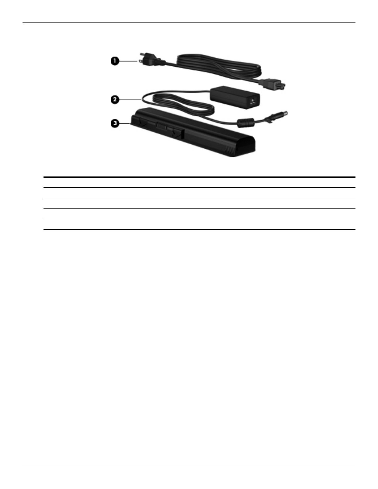
Additional hardware components
Item Component Description
(1) Power cord* Connects an AC adapter to an AC outlet.
(2) AC adapter Converts AC power to DC power.
(3) Battery* Powers the computer when the computer is not plugged into external power.
*Batteries and power cords vary in appearance by country or region.
2–12 Maintenance and Service Guide
Page 24
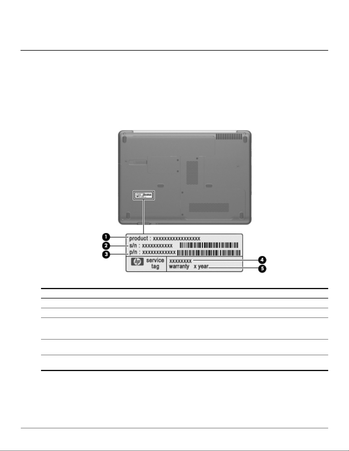
Service tag
When ordering parts or requesting information, provide the computer serial number and model number provided on
the service tag.
3
Illustrated parts catalog
Item Component Description
(1) Product name This is the product name affixed to the front of the computer.
(2) Serial number (s/n) This is an alphanumeric identifier that is unique to each product.
(3) Part number/Product number (p/n) This number provides specific information about the product’s
hardware components. The part number helps a service
technician to determine what components and parts are needed.
(4) Model description This is the alphanumeric identifier used to locate documents,
drivers, and support for the computer.
(5) Warranty period This number describes the duration of the warranty period for the
computer.
Maintenance and Service Guide 3–1
Page 25
Illustrated parts catalog
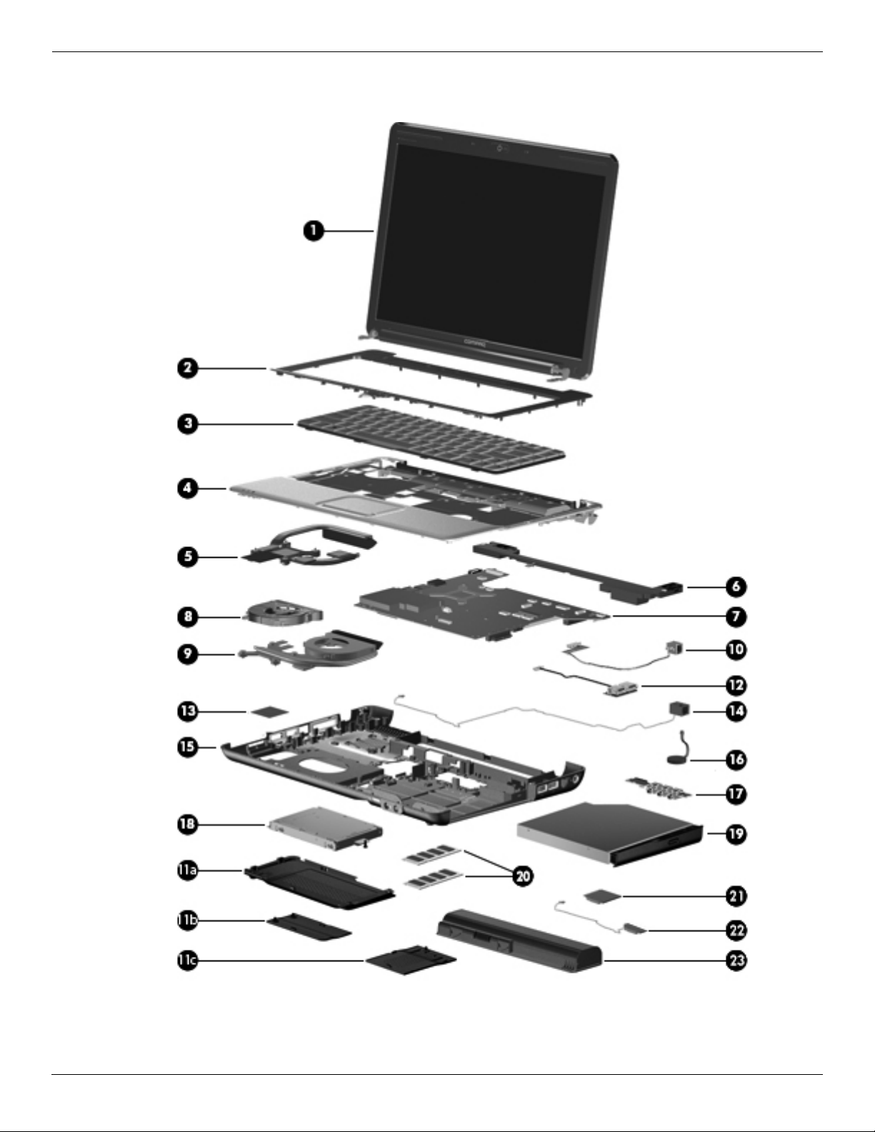
Computer major components
3–2 Maintenance and Service Guide
Page 26

Illustrated parts catalog
Item Description Spare Part Number
(1) Display assembly (See “Display assembly,” for more display assembly internal component spare part information.)
14.1-in WXGA BrightView display with a microphone for models with discrete graphics
subsystems
14.1-in WXGA BrightView display with a webcam/microphone for models with discrete
graphics subsystems
14.1-in WXGA BrightView display with a microphone for models with UMA graphics
subsystems
14.1-in WXGA BrightView display with a webcam/microphone for models with UMA
graphics subsystems
(2) Keyboard cover (includes power button board and cable) 487299-001
(3) Keyboard (includes keyboard cable):
For use in Latin America 486904-161
For use in South Korea 486904-AD1
For use in Taiwan 486904-AB1
For use in Thailand 486904-281
For use in the United States 486904-001
(4) Top cover (includes TouchPad and cable) 487300-001
(5) Heat sink for models with UMA graphics subsystems (includes thermal material) 575284-001
(6) Speaker assembly (includes speaker cable)
For use in India 486865-D61
For use in all countries and regions except India 486865-001
580763-001
580764-001
580765-001
580766-001
(7) System board (includes replacement thermal material):
For models equipped with discrete graphics subsystems 573719-001
For models equipped with UMA graphics subsystems 573720-001
(8) Fan for models with UMA graphics subsystems 486844-001
(9) Heat sink/fan for models with discrete graphics subsystems (includes thermal material) 575283-001
(10) Modem module (select models only)
For use in all countries and regions except Australia and New Zealand 510100-001
For use in Australia and New Zealand 510100-011
Modem module cable (includes RJ-11 connector) 494981-001
Plastics Kit (see “Plastics Kit” on page 3-9 for Plastics Kit spare part information) 498322-001
(Continued)
Maintenance and Service Guide 3–3
Page 27

Illustrated parts catalog
Item Description Spare Part Number
(11a) Hard drive cover
(11b) Memory module compartment cover
(11c) Mini Card compartment cover
(12) USB board 486842-001
USB board cable 486843-001
(13) WLAN module
Broadcom BCM4322 802.11a/b/g/n 2x2 for use in Afghanistan, Albania, Algeria, Andorra,
Angola, Antigua and Barbuda, Argentina, Armenia, Aruba, Australia, Austria, Azerbaijan,
the Bahamas, Bahrain, Bangladesh, Barbados, Belarus, Belgium, Belize, Benin, Bermuda,
Bhutan, Bolivia, Bosnia and Herzegovina, Botswana, Brazil, the British Virgin Islands,
Brunei, Bulgaria, Burkina Faso, Burundi, Cambodia, Cameroon, Cape Verde, the Central
African Republic, Chad, Colombia, Comoros, the Congo, Costa Rica, Croatia, Cyprus, the
Czech Republic, Denmark, Djibouti, Dominica, the Dominican Republic, East Timor,
Ecuador, Egypt, El Salvador, Equitorial Guinea, Eritrea, Estonia, Ethiopia, Fiji, Finland,
France, French Guiana, Gabon, Gambia, Georgia, Germany, Ghana, Gibraltar, Greece,
Grenada, Guadeloupe, Guatemala, Guinea, Guinea-Bissau, Guyana, Haiti, Honduras,
Hong Kong, Hungary, Iceland, India, Indonesia, Ireland, Israel, Italy, the Ivory Coast,
Jamaica, Japan, Jordan, Kazakhstan, Kenya, Kiribati, Kuwait, Kyrgyzstan, Laos, Latvia,
Lebanon, Lesotho, Liberia, Liechtenstein, Lithuania, Luxembourg, Macedonia, Madagascar,
Malawi, Malaysia, the Maldives, Mali, Malta, the Marshall Islands, Martinique, Mauritania,
Mauritius, Mexico, Micronesia, Monaco, Mongolia, Montenegro, Morocco, Mozambique,
Namibia, Nauru, Nepal, the Nether Antilles, the Netherlands, New Zealand, Nicaragua,
Niger, Nigeria, Norway, Oman, Pakistan, Palau, Panama, Papua New Guinea, Paraguay,
the People's Republic of China, Peru, the Philippines, Poland, Portugal, Qatar, the Republic
of Moldova, Romania, Russia, Rwanda, Samoa, San Marino, Sao Tome and Principe,
Saudi Arabia, Senegal, Serbia, the Seychelles, Sierra Leone, Singapore, Slovakia,
Slovenia, the Solomon Islands, Somalia, South Africa, South Korea, Spain, Sri Lanka, St.
Kitts and Nevis, St. Lucia, St. Vincent and the Grenadines, Suriname, Swaziland, Sweden,
Switzerland, Syria, Taiwan, Tajikistan, Tanzania, Thailand, Togo, Tonga, Trinidad and
To b a g o, Tu n isi a , Tu rkey, Tu r kme n i s tan , Tu valu, Uganda, Ukraine, the United Arab
Emirates, the United Kingdom, Uruguay, Uzbekistan, Vanuatu, Venezuela, Vietnam,
Yemen, Zaire, Zambia, and Zimbabwe
518434-002
(Continued)
3–4 Maintenance and Service Guide
Page 28

Illustrated parts catalog
Item Description Spare Part Number
Atheros AR5009 802.11a/b/g/n for use in Afghanistan, Albania, Algeria, Andorra, Angola,
Antigua and Barbuda, Argentina, Armenia, Aruba, Australia, Austria, Azerbaijan, the
Bahamas, Bahrain, Barbados, Belgium, Belize, Benin, Bermuda, Bhutan, Bosnia and
Herzegovina, Botswana, Brazil, the British Virgin Islands, Brunei, Bulgaria, Burkina Faso,
Burundi, Cambodia, Cameroon, Cape Verde, the Central African Republic, Chad, Chile,
Colombia, Comoros, the Congo, Costa Rica, Croatia, Cyprus, the Czech Republic,
Denmark, Djibouti, Dominica, the Dominican Republic, East Timor, Ecuador, Egypt, El
Salvador, Equatorial Guinea, Eritrea, Estonia, Ethiopia, Fiji, Finland, France, French
Guiana, Gabon, Gambia, Georgia, Germany, Ghana, Gibraltar, Greece, Grenada,
Guadeloupe, Guatemala, Guinea, Guinea-Bissau, Guyana, Haiti, Honduras, Hong Kong,
Hungary, Iceland, India, Indonesia, Ireland, Israel, Italy, the Ivory Coast, Jamaica, Japan,
Jordan, Kazakhstan, Kenya, Kiribati, Kuwait, Kyrgyzstan, Laos, Latvia, Lebanon, Lesotho,
Liberia, Liechtenstein, Lithuania, Luxembourg, Macedonia, Madagascar, Malawi, Malaysia,
the Maldives, Mali, Malta, the Marshall Islands, Martinique, Mauritania, Mauritius, Mexico,
Micronesia, Monaco, Mongolia, Montenegro, Morocco, Mozambique, Namibia, Nauru,
Nepal, the Nether Antilles, the Netherlands, New Zealand, Nicaragua, Niger, Nigeria,
Norway, Oman, Palau, Panama, Papua New Guinea, Paraguay, the People's Republic of
China, Peru, the Philippines, Poland, Portugal, the Republic of Moldova, Romania, Rwanda,
Samoa, San Marino, Sao Tome and Principe, Saudi Arabia, Senegal, Serbia, the
Seychelles, Sierra Leone, Singapore, Slovakia, Slovenia, the Solomon Islands, Somalia,
South Africa, South Korea, Spain, Sri Lanka, St. Kitts and Nevis, St. Lucia, St. Vincent and
the Grenadines, Suriname, Swaziland, Sweden, Switzerland, Syria, Taiwan, Tajikistan,
Tanzania, Thailand, Togo, Tonga, Trinidad and Tobago, Tunisia, Turkey, Turkmenistan,
Tuvalu, Uganda, the United Arab Emirates, the United Kingdom, Uruguay, Uzbekistan,
Vanuatu, Venezuela, Vietnam, Yemen, Zaire, Zambia, and Zimbabwe
Broadcom BCM4312 802.11b/g for use in Afghanistan, Albania, Algeria, Andorra, Angola,
Antigua and Barbuda, Argentina, Armenia, Aruba, Australia, Austria, Azerbaijan, the
Bahamas, Bahrain, Bangladesh, Barbados, Belarus, Belgium, Belize, Benin, Bermuda,
Bhutan, Bolivia, Bosnia and Herzegovina, Botswana, Brazil, the British Virgin Islands,
Brunei, Bulgaria, Burkina Faso, Burundi, Cambodia, Cameroon, Cape Verde, the Central
African Republic, Chad, Colombia, Comoros, the Congo, Costa Rica, Croatia, Cyprus, the
Czech Republic, Denmark, Djibouti, Dominica, the Dominican Republic, East Timor,
Ecuador, Egypt, El Salvador, Equitorial Guinea, Eritrea, Estonia, Ethiopia, Fiji, Finland,
France, French Guiana, Gabon, Gambia, Georgia, Germany, Ghana, Gibraltar, Greece,
Grenada, Guadeloupe, Guatemala, Guinea, Guinea-Bissau, Guyana, Haiti, Honduras,
Hong Kong, Hungary, Iceland, India, Indonesia, Ireland, Israel, Italy, the Ivory Coast,
Jamaica, Japan, Jordan, Kazakhstan, Kenya, Kiribati, Kuwait, Kyrgyzstan, Laos, Latvia,
Lebanon, Lesotho, Liberia, Liechtenstein, Lithuania, Luxembourg, Macedonia, Madagascar,
Malawi, Malaysia, the Maldives, Mali, Malta, the Marshall Islands, Martinique, Mauritania,
Mauritius, Mexico, Micronesia, Monaco, Mongolia, Montenegro, Morocco, Mozambique,
Namibia, Nauru, Nepal, the Nether Antilles, the Netherlands, New Zealand, Nicaragua,
Niger, Nigeria, Norway, Oman, Pakistan, Palau, Panama, Papua New Guinea, Paraguay,
the People's Republic of China, Peru, the Philippines, Poland, Portugal, Qatar, the Republic
of Moldova, Romania, Russia, Rwanda, Samoa, San Marino, Sao Tome and Principe,
Saudi Arabia, Senegal, Serbia, the Seychelles, Sierra Leone, Singapore, Slovakia,
Slovenia, the Solomon Islands, Somalia, South Africa, South Korea, Spain, Sri Lanka, St.
Kitts and Nevis, St. Lucia, St. Vincent and the Grenadines, Suriname, Swaziland, Sweden,
Switzerland, Syria, Taiwan, Tajikistan, Tanzania, Thailand, Togo, Tonga, Trinidad and
To b a g o, Tu n isi a , Tu rkey, Tu r kme n i s tan , Tu valu, Uganda, Ukraine, the United Arab
Emirates, the United Kingdom, Uruguay, Uzbekistan, Vanuatu, Venezuela, Vietnam,
Yemen, Zaire, Zambia, and Zimbabwe
518437-002
504593-004
(Continued)
Maintenance and Service Guide 3–5
Page 29

Illustrated parts catalog
Item Description Spare Part Number
Atheros AR9285 802.11b/g/n for use in Afghanistan, Albania, Algeria, Andorra, Angola,
Antigua and Barbuda, Argentina, Armenia, Aruba, Australia, Austria, Azerbaijan, the
Bahamas, Bahrain, Barbados, Belgium, Belize, Benin, Bermuda, Bhutan, Bosnia and
Herzegovina, Botswana, Brazil, the British Virgin Islands, Brunei, Bulgaria, Burkina Faso,
Burundi, Cambodia, Cameroon, Cape Verde, the Central African Republic, Chad, Chile,
Colombia, Comoros, the Congo, Costa Rica, Croatia, Cyprus, the Czech Republic,
Denmark, Djibouti, Dominica, the Dominican Republic, East Timor, Ecuador, Egypt, El
Salvador, Equatorial Guinea, Eritrea, Estonia, Ethiopia, Fiji, Finland, France, French
Guiana, Gabon, Gambia, Georgia, Germany, Ghana, Gibraltar, Greece, Grenada,
Guadeloupe, Guatemala, Guinea, Guinea-Bissau, Guyana, Haiti, Honduras, Hong Kong,
Hungary, Iceland, India, Indonesia, Ireland, Italy, the Ivory Coast, Jamaica, Japan, Jordan,
Kazakhstan, Kenya, Kiribati, Kuwait, Kyrgyzstan, Laos, Latvia, Lebanon, Lesotho, Liberia,
Liechtenstein, Lithuania, Luxembourg, Macedonia, Madagascar, Malawi, Malaysia, the
Maldives, Mali, Malta, the Marshall Islands, Martinique, Mauritania, Mauritius, Mexico,
Micronesia, Monaco, Mongolia, Montenegro, Morocco, Mozambique, Namibia, Nauru,
Nepal, the Nether Antilles, the Netherlands, New Zealand, Nicaragua, Niger, Nigeria,
Norway, Oman, Palau, Panama, Papua New Guinea, Paraguay, the People's Republic of
China, Peru, the Philippines, Poland, Portugal, the Republic of Moldova, Romania, Rwanda,
Samoa, San Marino, Sao Tome and Principe, Saudi Arabia, Senegal, Serbia, the
Seychelles, Sierra Leone, Singapore, Slovakia, Slovenia, the Solomon Islands, Somalia,
South Africa, South Korea, Spain, Sri Lanka, St. Kitts and Nevis, St. Lucia, St. Vincent and
the Grenadines, Suriname, Swaziland, Sweden, Switzerland, Syria, Taiwan, Tajikistan,
Tanzania, Thailand, Togo, Tonga, Trinidad and Tobago, Tunisia, Turkey, Turkmenistan,
Tuvalu, Uganda, the United Arab Emirates, the United Kingdom, Uruguay, Uzbekistan,
Vanuatu, Venezuela, Vietnam, Yemen, Zaire, Zambia, and Zimbabwe
Mini Card bracket (not illustrated) 577509-001
(14) Power connector and cable 486864-001
518436-002
(Continued)
3–6 Maintenance and Service Guide
Page 30

Illustrated parts catalog
Item Description Spare Part Number
(15) Base enclosure
For use in computer models with a modem module 492248-001
For use in computer models without a modem module 487359-001
Rubber Feet Kit (not illustrated, includes six rubber feet) 486863-001
(16) RTC battery (includes cable and double-sided tape) 486835-001
(17) Audio board 487344-001
Audio board cable 486841-001
(18) Hard drive (includes hard drive bracket):
500-GB, 5400-rpm 497775-001
320-GB, 7200-rpm 573330-001
320-GB, 5400-rpm 459611-004
250-GB, 7200-rpm 575567-001
250-GB, 5400-rpm 454605-002
160 GB, 7200 rpm 580846-001
160-GB, 5400-rpm 454925-002
Hard Drive Hardware Kit (contains screws and hard drive bracket; not illustrated) 482158-001
(19) Optical drive (includes bezel and bracket):
DVD±RW and CD-RW SuperMulti Double-Layer Combo Drive with LightScribe 573728-001
Blu-ray ROM with LightScribe DVD±R/RW SuperMulti Double-Layer Drive 573727-001
(20) Memory module (PC2-6400, 800-MHz, DDR2):
1024-MB 482168-001
2048-MB 482169-001
(21) Processor (includes replacement thermal material):
AMD Turion Ultra Dual-Core M600 processor (2.4-GHz, 2-MB L2 cache, 3.6 GT/s
HyperTransport speed)
AMD Turion Dual-Core M520 processor (2.3-GHz, 1-MB L2 cache, 3.6 GT/s
HyperTransport speed)
AMD Turion Dual-Core M500 processor (2.2-GHz, 1-MB L2 cache, 3.6 GT/s
HyperTransport speed)
AMD Athlon X2 Dual-Core M320 processor (2.1-GHz, 1-MB L2 cache, 3.2 GT/s
HyperTransport speed)
AMD Athlon X2 Dual-Core M300 processor (2.0-GHz, 1-MB L2 cache, 3.2 GT/s
HyperTransport speed)
AMD Sempron X2 Single-Core M100 processor (2.0-GHz, 512-KB L2 cache, 3.2 GT/s
HyperTransport speed)
576254-001
583055-001
576253-001
576252-001
578024-001
576251-001
(22) Bluetooth module (select models only) 537921-001
Bluetooth module cable 575285-001
(23) Battery
6-cell Li-Ion (2.2-Ah, 47-Wh)
Maintenance and Service Guide 3–7
484170-001
Page 31

Illustrated parts catalog
Display assembly
Item Description Spare part number
(1) Display bezel
For models with a microphone module 580767-001
For models with a webcam/microphone module 580768-001
Display Hinge Kit 486737-001
(2a) Left hinge and bracket
(2b) Right hinge and bracket
(3) Webcam/microphone module (select models only) 487287-001
(4) 14.1-in WXGA TFT BrightView display panel (includes display panel cable) 487351-001
(5) Display inverter 486736-001
(6) Microphone module and cable 517629-001
(7) Wireless antenna transceivers and cable
For models with discrete graphics subsystems 502979-001
For models with UMA graphics subsystems 489066-001
(8) Display enclosure 487284-001
Display cable (not illustrated) 486735-001
Display Screw Kit (not illustrated) 486730-001
Display Rubber Kit (not illustrated; includes rubber screw covers and LCD rubber pads) 487283-001
Internal display switch (not illustrated) 489862-001
3–8 Maintenance and Service Guide
Page 32

Plastics Kit
Illustrated parts catalog
Item Description Spare part number
Plastics Kit: 498322-001
(1) Hard drive cover (includes two captive screws)
(2) Memory module compartment cover
(3) Mini Card compartment cover
Maintenance and Service Guide 3–9
Page 33

Illustrated parts catalog
Mass storage devices
Item Description Spare part number
(1) Hard drive (includes hard drive bracket)
500-GB, 5400-rpm 497775-001
320-GB, 7200-rpm 573330-001
320-GB, 5400-rpm 459611-004
250-GB, 7200-rpm 575567-001
250-GB, 5400-rpm 454605-002
160-GB, 7200-rpm 580846-001
160-GB, 5400-rpm 454925-002
Hard Drive Hardware Kit (contains screws and hard drive bracket; not illustrated) 482158-001
(2) Optical drive (includes bezel and bracket):
DVD±RW and CD-RW SuperMulti Double-Layer Combo Drive with LightScribe 573728-001
Blu-ray ROM with LightScribe DVD±R/RW SuperMulti Double-Layer Drive 573727-011
3–10 Maintenance and Service Guide
Page 34

Miscellaneous parts
Description Spare part number
AC adapters
90-W PFC HP Smart Adapter 463955-001
65-W PFC HP Smart Adapter 463958-001
Power cords
For use in Argentina 490371-D01
For use in Australia 490371-011
For use in Brazil 490371-201
For use in Denmark 490371-081
For use in Europe, the Middle East, and Africa 490371-021
For use in India 490371-D61
For use in Israel 490371-BB1
For use in Italy 490371-061
For use in the People’s Republic of China 490371-AA1
For use in South Korea 490371-AD1
Illustrated parts catalog
For use in Switzerland 490371-111
For use in Taiwan 490371-AB1
For use in the United Kingdom and Singapore 490371-031
For use in the United States 490371-001
Screw Kit
Phillips PM3.0 × 3.0 screws
Phillips PM2.5 × 18.0 screws
Phillips PM2.5 × 10.0 screws
Phillips PM2.5 × 7.0 captive screws
Phillips PM2.5 × 6.0 screws
Phillips PM2.5 × 5.0 captive screws
Phillips PM2.5 × 5.0 screws
Phillips PM2.5 × 4.0 screws
Phillips PM2.5 × 3.0 screws
Phillips PM2.0 × 10.0 captive screws
Phillips PM2.0 × 4.0 screws
Phillips PM2.0 × 3.0 screws
Phillips PM2.0 × 2.0 screws
487298-001
Maintenance and Service Guide 3–11
Page 35

Illustrated parts catalog
Sequential part number listing
Spare part
number
454605-002 250-GB, 5400-rpm hard drive (includes bracket)
454925-002 160-GB, 5400-rpm hard drive (includes bracket)
459611-004 320-GB, 5400-rpm hard drive (includes bracket)
463955-001 90-W HP Smart Adapter
463958-001 65-W HP Smart Adapter
482158-001 Hard Drive Hardware Kit (contains screws and hard drive bracket)
482168-001 1024-MB memory module (PC2-6400, 800-MHz, DDR2)
482169-001 2048-MB memory module (PC2-6400, 800-MHz, DDR2)
484170-001 6-cell Li-Ion battery (2.2-Ah, 47-Wh)
486730-001 Display Screw Kit
486735-001 Display cable
486736-001 Display inverter
486737-001 Display Hinge Kit
Description
486835-001 RTC battery (includes cable and double-sided tape)
486841-001 Audio board cable
486842-001 USB board
486843-001 USB board cable
486844-001 Fan for models with UMA graphics subsystems
486863-001 Rubber Kit (includes six rubber computer feet)
486864-001 Power connector and cable
486865-001 Speaker assembly for use in all countries and regions except India
486865-D61 Speaker assembly for use in India
486904-001 Keyboard for use in the United States
486904-161 Keyboard for use in Latin America
486904-281 Keyboard for use in Thailand
486904-AB1 Keyboard for use in Taiwan
486904-AD1 Keyboard for use in South Korea
487283-001 Display Rubber Kit (includes rubber screw covers and LCD rubber pads)
487284-001 Display enclosure
487287-001 Webcam/microphone module (select models only)
487298-001 Screw Kit
487299-001 Keyboard cover (includes power button board and cable)
487300-001 Top cover (includes TouchPad and cable)
487344-001 Audio board
487351-001 14.1-in WXGA TFT BrightView display panel (includes display panel cable)
(Continued)
3–12 Maintenance and Service Guide
Page 36

Illustrated parts catalog
Spare part
number Description
487359-001 Base enclosure for models without a modem module
489066-001 Wireless antenna transceivers and cable for models with equipped UMA graphics subsystem
489862-001 Internal display switch
490371-001 Power cord for use in the United States
490371-011 Power cord for use in Australia
490371-021 Power cord for use in Europe, the Middle East, and Africa
490371-031 Power cord for use in the United Kingdom and Singapore
490371-061 Power cord for use in Italy
490371-081 Power cord for use in Denmark
490371-111 Power cord for use in Switzerland
490371-201 Power cord for use in Brazil
490371-AA1 Power cord for use in the People’s Republic of China
490371-AB1 Power cord for use in Taiwan
490371-AD1 Power cord for use in South Korea
490371-BB1 Power cord for use in Israel
490371-D01 Power cord for use in Argentina
490371-D61 Power cord for use in India
492248-001 Base enclosure for models with a modem module (select models only)
494981-001 Modem module cable (includes RJ-11 connector)
497775-001 500-GB, 5400-rpm hard drive (includes bracket)
498322-001 Plastics Kit
502979-001 Wireless antenna transceivers and cable for models equipped with discrete graphics subsystem
504593-004 Broadcom BCM4312 802.11b/g for use in Afghanistan, Albania, Algeria, Andorra, Angola, Antigua and
Barbuda, Argentina, Armenia, Aruba, Australia, Austria, Azerbaijan, the Bahamas, Bahrain, Bangladesh,
Barbados, Belarus, Belgium, Belize, Benin, Bermuda, Bhutan, Bolivia, Bosnia and Herzegovina,
Botswana, Brazil, the British Virgin Islands, Brunei, Bulgaria, Burkina Faso, Burundi, Cambodia,
Cameroon, Cape Verde, the Central African Republic, Chad, Colombia, Comoros, the Congo, Costa Rica,
Croatia, Cyprus, the Czech Republic, Denmark, Djibouti, Dominica, the Dominican Republic, East Timor,
Ecuador, Egypt, El Salvador, Equitorial Guinea, Eritrea, Estonia, Ethiopia, Fiji, Finland, France, French
Guiana, Gabon, Gambia, Georgia, Germany, Ghana, Gibraltar, Greece, Grenada, Guadeloupe,
Guatemala, Guinea, Guinea-Bissau, Guyana, Haiti, Honduras, Hong Kong, Hungary, Iceland, India,
Indonesia, Ireland, Israel, Italy, the Ivory Coast, Jamaica, Japan, Jordan, Kazakhstan, Kenya, Kiribati,
Kuwait, Kyrgyzstan, Laos, Latvia, Lebanon, Lesotho, Liberia, Liechtenstein, Lithuania, Luxembourg,
Macedonia, Madagascar, Malawi, Malaysia, the Maldives, Mali, Malta, the Marshall Islands, Martinique,
Mauritania, Mauritius, Mexico, Micronesia, Monaco, Mongolia, Montenegro, Morocco, Mozambique,
Namibia, Nauru, Nepal, the Nether Antilles, the Netherlands, New Zealand, Nicaragua, Niger, Nigeria,
Norway, Oman, Pakistan, Palau, Panama, Papua New Guinea, Paraguay, the People's Republic of China,
Peru, the Philippines, Poland, Portugal, Qatar, the Republic of Moldova, Romania, Russia, Rwanda,
Samoa, San Marino, Sao Tome and Principe, Saudi Arabia, Senegal, Serbia, the Seychelles, Sierra
Leone, Singapore, Slovakia, Slovenia, the Solomon Islands, Somalia, South Africa, South Korea, Spain,
Sri Lanka, St. Kitts and Nevis, St. Lucia, St. Vincent and the Grenadines, Suriname, Swaziland, Sweden,
Switzerland, Syria, Taiwan, Tajikistan, Tanzania, Thailand, Togo, Tonga, Trinidad and Tobago, Tunisia,
Turkey, Turkmenistan, Tuvalu, Uganda, Ukraine, the United Arab Emirates, the United Kingdom, Uruguay,
Uzbekistan, Vanuatu, Venezuela, Vietnam, Yemen, Zaire, Zambia, and Zimbabwe
510100-001 Modem module for use in all countries and regions except Australia and New Zealand (select models only)
(Continued)
Maintenance and Service Guide 3–13
Page 37

Illustrated parts catalog
Spare part
number Description
510100-011 Modem module for use in Australia and New Zealand (select models only)
517629-001 Microphone module and cable
518434-002 Broadcom BCM4322 802.11a/b/g/n 2x2 for use in Afghanistan, Albania, Algeria, Andorra, Angola, Antigua
and Barbuda, Argentina, Armenia, Aruba, Australia, Austria, Azerbaijan, the Bahamas, Bahrain,
Bangladesh, Barbados, Belarus, Belgium, Belize, Benin, Bermuda, Bhutan, Bolivia, Bosnia and
Herzegovina, Botswana, Brazil, the British Virgin Islands, Brunei, Bulgaria, Burkina Faso, Burundi,
Cambodia, Cameroon, Cape Verde, the Central African Republic, Chad, Colombia, Comoros, the Congo,
Costa Rica, Croatia, Cyprus, the Czech Republic, Denmark, Djibouti, Dominica, the Dominican Republic,
East Timor, Ecuador, Egypt, El Salvador, Equitorial Guinea, Eritrea, Estonia, Ethiopia, Fiji, Finland,
France, French Guiana, Gabon, Gambia, Georgia, Germany, Ghana, Gibraltar, Greece, Grenada,
Guadeloupe, Guatemala, Guinea, Guinea-Bissau, Guyana, Haiti, Honduras, Hong Kong, Hungary,
Iceland, India, Indonesia, Ireland, Israel, Italy, the Ivory Coast, Jamaica, Japan, Jordan, Kazakhstan,
Kenya, Kiribati, Kuwait, Kyrgyzstan, Laos, Latvia, Lebanon, Lesotho, Liberia, Liechtenstein, Lithuania,
Luxembourg, Macedonia, Madagascar, Malawi, Malaysia, the Maldives, Mali, Malta, the Marshall Islands,
Martinique, Mauritania, Mauritius, Mexico, Micronesia, Monaco, Mongolia, Montenegro, Morocco,
Mozambique, Namibia, Nauru, Nepal, the Nether Antilles, the Netherlands, New Zealand, Nicaragua,
Niger, Nigeria, Norway, Oman, Pakistan, Palau, Panama, Papua New Guinea, Paraguay, the People's
Republic of China, Peru, the Philippines, Poland, Portugal, Qatar, the Republic of Moldova, Romania,
Russia, Rwanda, Samoa, San Marino, Sao Tome and Principe, Saudi Arabia, Senegal, Serbia, the
Seychelles, Sierra Leone, Singapore, Slovakia, Slovenia, the Solomon Islands, Somalia, South Africa,
South Korea, Spain, Sri Lanka, St. Kitts and Nevis, St. Lucia, St. Vincent and the Grenadines, Suriname,
Swaziland, Sweden, Switzerland, Syria, Taiwan, Tajikistan, Tanzania, Thailand, Togo, Tonga, Trinidad and
Tobago, Tunisia, Turkey, Turkmenistan, Tuvalu, Uganda, Ukraine, the United Arab Emirates, the United
Kingdom, Uruguay, Uzbekistan, Vanuatu, Venezuela, Vietnam, Yemen, Zaire, Zambia, and Zimbabwe
518436-002 Atheros AR9285 802.11b/g/n for use in Afghanistan, Albania, Algeria, Andorra, Angola, Antigua and
Barbuda, Argentina, Armenia, Aruba, Australia, Austria, Azerbaijan, the Bahamas, Bahrain, Barbados,
Belgium, Belize, Benin, Bermuda, Bhutan, Bosnia and Herzegovina, Botswana, Brazil, the British Virgin
Islands, Brunei, Bulgaria, Burkina Faso, Burundi, Cambodia, Cameroon, Cape Verde, the Central African
Republic, Chad, Chile, Colombia, Comoros, the Congo, Costa Rica, Croatia, Cyprus, the Czech Republic,
Denmark, Djibouti, Dominica, the Dominican Republic, East Timor, Ecuador, Egypt, El Salvador,
Equatorial Guinea, Eritrea, Estonia, Ethiopia, Fiji, Finland, France, French Guiana, Gabon, Gambia,
Georgia, Germany, Ghana, Gibraltar, Greece, Grenada, Guadeloupe, Guatemala, Guinea,
Guinea-Bissau, Guyana, Haiti, Honduras, Hong Kong, Hungary, Iceland, India, Indonesia, Ireland, Italy,
the Ivory Coast, Jamaica, Japan, Jordan, Kazakhstan, Kenya, Kiribati, Kuwait, Kyrgyzstan, Laos, Latvia,
Lebanon, Lesotho, Liberia, Liechtenstein, Lithuania, Luxembourg, Macedonia, Madagascar, Malawi,
Malaysia, the Maldives, Mali, Malta, the Marshall Islands, Martinique, Mauritania, Mauritius, Mexico,
Micronesia, Monaco, Mongolia, Montenegro, Morocco, Mozambique, Namibia, Nauru, Nepal, the Nether
Antilles, the Netherlands, New Zealand, Nicaragua, Niger, Nigeria, Norway, Oman, Palau, Panama, Papua
New Guinea, Paraguay, the People's Republic of China, Peru, the Philippines, Poland, Portugal, the
Republic of Moldova, Romania, Rwanda, Samoa, San Marino, Sao Tome and Principe, Saudi Arabia,
Senegal, Serbia, the Seychelles, Sierra Leone, Singapore, Slovakia, Slovenia, the Solomon Islands,
Somalia, South Africa, South Korea, Spain, Sri Lanka, St. Kitts and Nevis, St. Lucia, St. Vincent and the
Grenadines, Suriname, Swaziland, Sweden, Switzerland, Syria, Taiwan, Tajikistan, Tanzania, Thailand,
Togo, Tonga, Trinidad and Tobago, Tunisia, Turkey, Turkmenistan, Tuvalu, Uganda, the United Arab
Emirates, the United Kingdom, Uruguay, Uzbekistan, Vanuatu, Venezuela, Vietnam, Yemen, Zaire,
Zambia, and Zimbabwe
(Continued)
3–14 Maintenance and Service Guide
Page 38

Illustrated parts catalog
Spare part
number Description
518437-002 Atheros AR5009 802.11a/b/g/n for use in Afghanistan, Albania, Algeria, Andorra, Angola, Antigua and
Barbuda, Argentina, Armenia, Aruba, Australia, Austria, Azerbaijan, the Bahamas, Bahrain, Barbados,
Belgium, Belize, Benin, Bermuda, Bhutan, Bosnia and Herzegovina, Botswana, Brazil, the British Virgin
Islands, Brunei, Bulgaria, Burkina Faso, Burundi, Cambodia, Cameroon, Cape Verde, the Central African
Republic, Chad, Chile, Colombia, Comoros, the Congo, Costa Rica, Croatia, Cyprus, the Czech Republic,
Denmark, Djibouti, Dominica, the Dominican Republic, East Timor, Ecuador, Egypt, El Salvador,
Equatorial Guinea, Eritrea, Estonia, Ethiopia, Fiji, Finland, France, French Guiana, Gabon, Gambia,
Georgia, Germany, Ghana, Gibraltar, Greece, Grenada, Guadeloupe, Guatemala, Guinea,
Guinea-Bissau, Guyana, Haiti, Honduras, Hong Kong, Hungary, Iceland, India, Indonesia, Ireland, Israel,
Italy, the Ivory Coast, Jamaica, Japan, Jordan, Kazakhstan, Kenya, Kiribati, Kuwait, Kyrgyzstan, Laos,
Latvia, Lebanon, Lesotho, Liberia, Liechtenstein, Lithuania, Luxembourg, Macedonia, Madagascar,
Malawi, Malaysia, the Maldives, Mali, Malta, the Marshall Islands, Martinique, Mauritania, Mauritius,
Mexico, Micronesia, Monaco, Mongolia, Montenegro, Morocco, Mozambique, Namibia, Nauru, Nepal, the
Nether Antilles, the Netherlands, New Zealand, Nicaragua, Niger, Nigeria, Norway, Oman, Palau,
Panama, Papua New Guinea, Paraguay, the People's Republic of China, Peru, the Philippines, Poland,
Portugal, the Republic of Moldova, Romania, Rwanda, Samoa, San Marino, Sao Tome and Principe,
Saudi Arabia, Senegal, Serbia, the Seychelles, Sierra Leone, Singapore, Slovakia, Slovenia, the Solomon
Islands, Somalia, South Africa, South Korea, Spain, Sri Lanka, St. Kitts and Nevis, St. Lucia, St. Vincent
and the Grenadines, Suriname, Swaziland, Sweden, Switzerland, Syria, Taiwan, Tajikistan, Tanzania,
Thailand, Togo, Tonga, Trinidad and Tobago, Tunisia, Turkey, Turkmenistan, Tuvalu, Uganda, the United
Arab Emirates, the United Kingdom, Uruguay, Uzbekistan, Vanuatu, Venezuela, Vietnam, Yemen, Zaire,
Zambia, and Zimbabwe
537921-001 Bluetooth module (select models only)
573330-001 320-GB, 7200-rpm hard drive (includes bracket)
573719-001 System board for models equipped with a discrete graphics subsystem (includes thermal material)
573720-001 System board for models with UMA graphics subsystems (includes thermal material)
573727-001 Blu-ray ROM with LightScribe DVD±R/RW SuperMulti Double-Layer Drive
573728-001 DVD±RW and CD-RW SuperMulti Double-Layer Combo Drive with LightScribe
575283-001 Heat sink/fan for models with discrete graphics subsystems (includes thermal material)
575284-001 Heat sink for models with UMA graphics subsystems (includes thermal material)
575285-001 Bluetooth module cable (select models only)
575567-001 250-GB, 7200-rpm hard drive (includes bracket)
576251-001 AMD Sempron X2 Single-Core M100 processor (2.0-GHz, 512-KB L2 cache, 3.2 GT/s HyperTransport
speed)
576252-001 AMD Athlon X2 Dual-Core M320 processor (2.1-GHz, 1-MB L2 cache, 3.2 GT/s HyperTransport speed)
576253-001 AMD Turion Dual-Core M500 processor (2.2-GHz, 1-MB L2 cache, 3.6 GT/s HyperTransport speed)
576254-001 AMD Turion Ultra Dual-Core M600 processor (2.4-GHz, 2-MB L2 cache, 3.6 GT/s HyperTransport speed)
577509-001 Mini Card bracket
578024-001 AMD Athlon X2 Dual-Core M300 processor (2.0-GHz, 1-MB L2 cache, 3.2 GT/s HyperTransport speed)
580763-001 14.1-in WXGA BrightView display with a microphone module for models with discrete graphics
subsystems
580764-001 14.1-in WXGA BrightView display with a webcam/microphone module for models with discrete graphics
subsystems
580765-001 14.1-in WXGA BrightView display with a webcam/microphone module for models with UMA graphics
subsystems
580766-001 14.1-in WXGA BrightView display with a webcam/microphone module for models with UMA graphics
subsystems
(Continued)
Maintenance and Service Guide 3–15
Page 39

Illustrated parts catalog
Spare part
number Description
580767-001 Display bezel for models with a microphone module
580768-001 Display bezel for models with a webcam/microphone module
580846-001 160-GB, 7200-rpm hard drive (includes bracket)
583055-001 AMD Turion Dual-Core M520 processor (2.3-GHz, 1-MB L2 cache, 3.6 GT/s HyperTransport speed)
3–16 Maintenance and Service Guide
Page 40

Removal and replacement procedures
Preliminary replacement requirements
Tools required
You will need the following tools to complete the removal and replacement procedures:
■ Flat-bladed screwdriver
■ Magnetic screwdriver
■ Phillips P0 and P1 screwdrivers
Service considerations
The following sections include some of the considerations that you must keep in mind during disassembly and
assembly procedures.
4
As you remove each subassembly from the computer, place the subassembly (and all accompanying screws) away
✎
from the work area to prevent damage.
Plastic parts
CAUTION: Using excessive force during disassembly and reassembly can damage plastic parts. Use care when
Ä
handling the plastic parts. Apply pressure only at the points designated in the maintenance instructions.
Cables and connectors
CAUTION: When servicing the computer, be sure that cables are placed in their proper locations during the
Ä
reassembly process. Improper cable placement can damage the computer.
Cables must be handled with extreme care to avoid damage. Apply only the tension required to unseat or seat the
cables during removal and insertion. Handle cables by the connector whenever possible. In all cases, avoid
bending, twisting, or tearing cables. Be sure that cables are routed in such a way that they cannot be caught or
snagged by parts being removed or replaced. Handle flex cables with extreme care; these cables tear easily.
Maintenance and Service Guide 4–1
Page 41

Removal and replacement procedures
Drive handling
CAUTION: Drives are fragile components that must be handled with care. To prevent damage to the computer,
Ä
damage to a drive, or loss of information, observe these precautions:
■ Before removing or inserting a hard drive, shut down the computer. If you are unsure whether the computer is off
or in Hibernation, turn the computer on, and then shut it down through the operating system.
■ Before handling a drive, be sure that you are discharged of static electricity. While handling a drive, avoid
touching the connector.
■ Before removing a diskette drive or optical drive, be sure that a diskette or disc is not in the drive and be sure
that the optical drive tray is closed.
■ Handle drives on surfaces covered with at least one inch of shock-proof foam.
■ Avoid dropping drives from any height onto any surface.
■ After removing a hard drive, an optical drive, or a diskette drive, place it in a static-proof bag.
■ Avoid exposing a hard drive to products that have magnetic fields, such as monitors or speakers.
■ Avoid exposing a drive to temperature extremes or liquids.
■ If a drive must be mailed, place the drive in a bubble pack mailer or other suitable form of protective packaging
and label the package “FRAGILE.”
Grounding guidelines
Electrostatic discharge damage
Electronic components are sensitive to electrostatic discharge (ESD). Circuitry design and structure determine the
degree of sensitivity. Networks built into many integrated circuits provide some protection, but in many cases, ESD
contains enough power to alter device parameters or melt silicon junctions.
A discharge of static electricity from a finger or other conductor can destroy static-sensitive devices or
microcircuitry. Even if the spark is neither felt nor heard, damage may have occurred.
An electronic device exposed to ESD may not be affected at all and may work perfectly throughout a normal cycle.
Or the device may function normally for a while, and then degrade in the internal layers, reducing its life
expectancy.
CAUTION: To prevent damage to the computer when you are removing or installing internal components, observe
Ä
these precautions:
■ Keep components in their electrostatic-safe containers until you are ready to install them.
■ Use nonmagnetic tools.
■ Before touching an electronic component, discharge static electricity by using the guidelines described in
this section.
■ Avoid touching pins, leads, and circuitry. Handle electronic components as little as possible.
■ If you remove a component, place it in an electrostatic-safe container.
4–2 Maintenance and Service Guide
Page 42

Removal and replacement procedures
The following table shows how humidity affects the electrostatic voltage levels generated by different activities.
CAUTION: A product can be degraded by as little as 700 V.
Ä
Typical electrostatic voltage levels
Relative humidity
Event 10% 40% 55%
Walking across carpet 35,000 V 15,000 V 7,500 V
Walking across vinyl floor 12,000 V 5,000 V 3,000 V
Motions of bench worker 6,000 V 800 V 400 V
Removing DIPS from plastic tube 2,000 V 700 V 400 V
Removing DIPS from vinyl tray 11,500 V 4,000 V 2,000 V
Removing DIPS from Styrofoam 14,500 V 5,000 V 3,500 V
Removing bubble pack from PCB 26,500 V 20,000 V 7,000 V
Packing PCBs in foam-lined box 21,000 V 11,000 V 5,000 V
Packaging and transporting guidelines
Follow these grounding guidelines when packaging and transporting equipment:
■ To avoid hand contact, transport products in static-safe tubes, bags, or boxes.
■ Protect ESD-sensitive parts and assemblies with conductive or approved containers or packaging.
■ Keep ESD-sensitive parts in their containers until the parts arrive at static-free workstations.
■ Place items on a grounded surface before removing items from their containers.
■ Always be properly grounded when touching a component or assembly.
■ Store reusable ESD-sensitive parts from assemblies in protective packaging or nonconductive foam.
■ Use transporters and conveyors made of antistatic belts and roller bushings. Be sure that mechanized equipment
used for moving materials is wired to ground and that proper materials are selected to avoid static charging.
When grounding is not possible, use an ionizer to dissipate electric charges.
Workstation guidelines
Follow these grounding workstation guidelines:
■ Cover the workstation with approved static-shielding material.
■ Use a wrist strap connected to a properly grounded work surface and use properly grounded tools and
equipment.
■ Use conductive field service tools, such as cutters, screwdrivers, and vacuums.
■ When fixtures must directly contact dissipative surfaces, use fixtures made only of static-safe materials.
■ Keep the work area free of nonconductive materials, such as ordinary plastic assembly aids and Styrofoam.
■ Handle ESD-sensitive components, parts, and assemblies by the case or PCM laminate. Handle these items
only at static-free workstations.
■ Avoid contact with pins, leads, or circuitry.
■ Turn off power and input signals before inserting or removing connectors or test equipment.
Maintenance and Service Guide 4–3
Page 43

Removal and replacement procedures
Equipment guidelines
Grounding equipment must include either a wrist strap or a foot strap at a grounded workstation.
■ When seated, wear a wrist strap connected to a grounded system. Wrist straps are flexible straps with a
minimum of one megohm ±10% resistance in the ground cords. To provide proper ground, wear a strap snugly
against the skin at all times. On grounded mats with banana-plug connectors, use alligator clips to connect a
wrist strap.
■ When standing, use foot straps and a grounded floor mat. Foot straps (heel, toe, or boot straps) can be used at
standing workstations and are compatible with most types of shoes or boots. On conductive floors or
dissipative floor mats, use foot straps on both feet with a minimum of one megohm resistance between the
operator and ground. To be effective, the conductive strips must be worn in contact with the skin.
The following grounding equipment is recommended to prevent electrostatic damage:
■ Antistatic tape
■ Antistatic smocks, aprons, and sleeve protectors
■ Conductive bins and other assembly or soldering aids
■ Nonconductive foam
■ Conductive tabletop workstations with ground cords of one megohm resistance
■ Static-dissipative tables or floor mats with hard ties to the ground
■ Field service kits
■ Static awareness labels
■ Material-handling packages
■ Nonconductive plastic bags, tubes, or boxes
■ Metal tote boxes
■ Electrostatic voltage levels and protective materials
The following table lists the shielding protection provided by antistatic bags and floor mats.
Material Use Voltage protection level
Antistatic plastic Bags 1,500 V
Carbon-loaded plastic Floor mats 7,500 V
Metallized laminate Floor mats 5,000 V
4–4 Maintenance and Service Guide
Page 44

Component replacement procedures
This chapter provides removal and replacement procedures.
There are as many as 78 screws, in 13 different sizes, that must be removed, replaced, or loosened when servicing
the computer. Make special note of each screw size and location during removal and replacement.
Service tag
When ordering parts or requesting information, provide the computer serial number and model number provided on
the service tag.
Removal and replacement procedures
Item Component Description
(1) Product name This is the product name affixed to the front of the computer.
(2) Serial number (s/n) This is an alphanumeric identifier that is unique to each product.
(3) Part number/Product number (p/n) This number provides specific information about the product’s
hardware components. The part number helps a service
technician to determine what components and parts are needed.
(4) Model description This is the alphanumeric identifier used to locate documents,
drivers, and support for the computer.
(5) Warranty period This number describes the duration of the warranty period for the
computer.
Maintenance and Service Guide 4–5
Page 45

Removal and replacement procedures
Computer feet
The computer feet are adhesive-backed rubber pads. The feet are included in the Rubber Kit, spare part number
486863-001. There are 6 rubber feet that attach to the base enclosure in the locations illustrated below.
4–6 Maintenance and Service Guide
Page 46

Battery
Removal and replacement procedures
Description Spare part number
6-cell Li-Ion battery (2.2-Ah, 47-Wh) 484170-001
Before disassembling the computer, follow these steps:
1. Shut down the computer. If you are unsure whether the computer is off or in Hibernation, turn the computer on,
and then shut it down through the operating system.
2. Disconnect all external devices connected to the computer.
3. Disconnect the power from the computer by first unplugging the power cord from the AC outlet and then
unplugging the AC adapter from the computer.
Remove the battery:
1. Turn the computer upside down on a flat surface, with the battery bay toward you.
2. Slide the battery release latch 1 to release the battery.
3. Pivot the battery 2 upward and lift it out of the computer 3.
To insert the battery, insert the rear edge of the battery into the battery bay and pivot the front edge downward until
the battery is seated. The battery release latch automatically locks the battery into place
Maintenance and Service Guide 4–7
Page 47

Removal and replacement procedures
Hard drive
Description Spare part number
500-GB, 5400-rpm hard drive 497775-001
320-GB, 7200-rpm hard drive 573330-001
320-GB, 5400-rpm hard drive 459611-004
250-GB, 7200-rpm hard drive 575567-001
250-GB, 5400-rpm hard drive 454605-002
160-GB, 7200-rpm hard drive 580846-001
160-GB, 5400-rpm hard drive 454925-002
Hard Drive Hardware Kit (includes hard drive connector, hard drive bracket, and screws) 482158-001
Before removing the hard drive, follow these steps:
1. Shut down the computer. If you are unsure whether the computer is off or in Hibernation, turn the computer on,
and then shut it down through the operating system.
2. Disconnect all external devices connected to the computer.
3. Disconnect the power from the computer by first unplugging the power cord from the AC outlet and then
unplugging the AC adapter from the computer.
4. Remove the battery (see “Battery” on page 4-7).
Remove the hard drive:
1. Position the computer with the front toward you.
2. Loosen the two Phillips PM2.5×5.0 captive screws 1 that secure the hard drive cover to the computer.
3. Lift the left side 2 of the hard drive cover, swing it to the right, and remove the cover 3. The hard drive cover
is included in the Plastics Kit, spare part number 498322-001.
4–8 Maintenance and Service Guide
Page 48

Removal and replacement procedures
4. Remove the three Phillips PM2.0×4.0 screws 1 that secure the hard drive to the computer.
5. Use the Mylar tab 2 on the hard drive to slide the hard drive 3 to the left.
6. Remove the hard drive 4 from the hard drive bay.
7. If it is necessary to replace the hard drive bracket, follow these steps:
a. Remove the two Phillips PM3.0×3.0 screws 1 from each side of the hard drive.
b. Lift the bracket 2 straight up to remove it from the hard drive.
Reverse this procedure to reassemble and install the hard drive.
Maintenance and Service Guide 4–9
Page 49

Removal and replacement procedures
Memory module
Description Spare part number
1024-MB (PC2-6400, 800-MHz, DDR2) 482168-001
2048-MB (PC2-6400, 800-MHz, DDR2) 482169-001
Before removing the memory module, follow these steps:
1. Shut down the computer. If you are unsure whether the computer is off or in Hibernation, turn the computer on,
and then shut it down through the operating system.
2. Disconnect all external devices connected to the computer.
3. Disconnect the power from the computer by first unplugging the power cord from the AC outlet and then
unplugging the AC adapter from the computer.
4. Remove the battery (see “Battery” on page 4-7).
5. Remove the hard drive cover (see “Hard drive” on page 4-8).
Remove the memory module:
The top memory module slot is for expansion memory and the bottom slot is for primary memory.
✎
1. Position the computer with the front toward you.
2. Loosen the Phillips PM2.5×7.0 captive screw 1 that secures the memory module compartment cover to the
computer.
3. Lift the right side of the cover 2, swing it to the left, and lift the cover off the computer 3. The memory
module compartment cover is included in the Plastics Kit, spare part number 498322-001.
4–10 Maintenance and Service Guide
Page 50

Removal and replacement procedures
4. Spread the retaining tabs 1 on each side of the memory module to release the memory module. (The edge of
the module opposite the slot rises away from the computer.)
5. Remove the memory module 2 by pulling the module away from the slot at an angle.
Memory modules are designed with a notch 3 to prevent incorrect insertion into the memory
✎
module
slot.
Reverse this procedure to install a memory module.
Maintenance and Service Guide 4–11
Page 51

Removal and replacement procedures
RTC battery
Description Spare part number
RTC battery (includes cable and double-sided tape) 486835-001
Before removing the RTC battery, follow these steps:
1. Shut down the computer. If you are unsure whether the computer is off or in Hibernation, turn the computer on,
and then shut it down through the operating system.
2. Disconnect all external devices connected to the computer.
3. Disconnect the power from the computer by first unplugging the power cord from the AC outlet and then
unplugging the AC adapter from the computer.
4. Remove the battery (see “Battery” on page 4-7).
Remove the RTC battery:
1. Loosen the two Phillips PM2.5×5.0 captive screws 1 that secure the Mini Card compartment cover to the
computer.
2. Lift the right side of the Mini Card compartment cover 2, swing it to the left, and remove the cover 3.
4–12 Maintenance and Service Guide
Page 52

3. Disconnect the RTC battery cable 1 from the system board.
4. Release the two-sided tape 2 that holds the RTC battery.
5. Remove the RTC battery 3.
Reverse this procedure to install the RTC battery.
Removal and replacement procedures
Maintenance and Service Guide 4–13
Page 53

Removal and replacement procedures
WLAN module
Description Spare part number
Broadcom BCM4322 802.11a/b/g/n 2x2 for use in Afghanistan, Albania, Algeria, Andorra, Angola,
Antigua and Barbuda, Argentina, Armenia, Aruba, Australia, Austria, Azerbaijan, the Bahamas,
Bahrain, Bangladesh, Barbados, Belarus, Belgium, Belize, Benin, Bermuda, Bhutan, Bolivia, Bosnia
and Herzegovina, Botswana, Brazil, the British Virgin Islands, Brunei, Bulgaria, Burkina Faso,
Burundi, Cambodia, Cameroon, Cape Verde, the Central African Republic, Chad, Colombia,
Comoros, the Congo, Costa Rica, Croatia, Cyprus, the Czech Republic, Denmark, Djibouti,
Dominica, the Dominican Republic, East Timor, Ecuador, Egypt, El Salvador, Equitorial Guinea,
Eritrea, Estonia, Ethiopia, Fiji, Finland, France, French Guiana, Gabon, Gambia, Georgia, Germany,
Ghana, Gibraltar, Greece, Grenada, Guadeloupe, Guatemala, Guinea, Guinea-Bissau, Guyana,
Haiti, Honduras, Hong Kong, Hungary, Iceland, India, Indonesia, Ireland, Israel, Italy, the Ivory
Coast, Jamaica, Japan, Jordan, Kazakhstan, Kenya, Kiribati, Kuwait, Kyrgyzstan, Laos, Latvia,
Lebanon, Lesotho, Liberia, Liechtenstein, Lithuania, Luxembourg, Macedonia, Madagascar,
Malawi, Malaysia, the Maldives, Mali, Malta, the Marshall Islands, Martinique, Mauritania, Mauritius,
Mexico, Micronesia, Monaco, Mongolia, Montenegro, Morocco, Mozambique, Namibia, Nauru,
Nepal, the Nether Antilles, the Netherlands, New Zealand, Nicaragua, Niger, Nigeria, Norway,
Oman, Pakistan, Palau, Panama, Papua New Guinea, Paraguay, the People's Republic of China,
Peru, the Philippines, Poland, Portugal, Qatar, the Republic of Moldova, Romania, Russia, Rwanda,
Samoa, San Marino, Sao Tome and Principe, Saudi Arabia, Senegal, Serbia, the Seychelles, Sierra
Leone, Singapore, Slovakia, Slovenia, the Solomon Islands, Somalia, South Africa, South Korea,
Spain, Sri Lanka, St. Kitts and Nevis, St. Lucia, St. Vincent and the Grenadines, Suriname,
Swaziland, Sweden, Switzerland, Syria, Taiwan, Tajikistan, Tanzania, Thailand, Togo, Tonga,
Trinidad and Tobago, Tunisia, Turkey, Turkmenistan, Tuvalu, Uganda, Ukraine, the United Arab
Emirates, the United Kingdom, Uruguay, Uzbekistan, Vanuatu, Venezuela, Vietnam, Yemen, Zaire,
Zambia, and Zimbabwe
Atheros AR5009 802.11a/b/g/n for use in Afghanistan, Albania, Algeria, Andorra, Angola, Antigua
and Barbuda, Argentina, Armenia, Aruba, Australia, Austria, Azerbaijan, the Bahamas, Bahrain,
Barbados, Belgium, Belize, Benin, Bermuda, Bhutan, Bosnia and Herzegovina, Botswana, Brazil,
the British Virgin Islands, Brunei, Bulgaria, Burkina Faso, Burundi, Cambodia, Cameroon, Cape
Verde, the Central African Republic, Chad, Chile, Colombia, Comoros, the Congo, Costa Rica,
Croatia, Cyprus, the Czech Republic, Denmark, Djibouti, Dominica, the Dominican Republic, East
Timor, Ecuador, Egypt, El Salvador, Equatorial Guinea, Eritrea, Estonia, Ethiopia, Fiji, Finland,
France, French Guiana, Gabon, Gambia, Georgia, Germany, Ghana, Gibraltar, Greece, Grenada,
Guadeloupe, Guatemala, Guinea, Guinea-Bissau, Guyana, Haiti, Honduras, Hong Kong, Hungary,
Iceland, India, Indonesia, Ireland, Israel, Italy, the Ivory Coast, Jamaica, Japan, Jordan,
Kazakhstan, Kenya, Kiribati, Kuwait, Kyrgyzstan, Laos, Latvia, Lebanon, Lesotho, Liberia,
Liechtenstein, Lithuania, Luxembourg, Macedonia, Madagascar, Malawi, Malaysia, the Maldives,
Mali, Malta, the Marshall Islands, Martinique, Mauritania, Mauritius, Mexico, Micronesia, Monaco,
Mongolia, Montenegro, Morocco, Mozambique, Namibia, Nauru, Nepal, the Nether Antilles, the
Netherlands, New Zealand, Nicaragua, Niger, Nigeria, Norway, Oman, Palau, Panama, Papua New
Guinea, Paraguay, the People's Republic of China, Peru, the Philippines, Poland, Portugal, the
Republic of Moldova, Romania, Rwanda, Samoa, San Marino, Sao Tome and Principe, Saudi
Arabia, Senegal, Serbia, the Seychelles, Sierra Leone, Singapore, Slovakia, Slovenia, the Solomon
Islands, Somalia, South Africa, South Korea, Spain, Sri Lanka, St. Kitts and Nevis, St. Lucia, St.
Vincent and the Grenadines, Suriname, Swaziland, Sweden, Switzerland, Syria, Taiwan, Tajikistan,
Tanzania, Thailand, Togo, Tonga, Trinidad and To ba go, Tuni s i a , Tur k e y, Tur km e nis t a n , Tuval u ,
Uganda, the United Arab Emirates, the United Kingdom, Uruguay, Uzbekistan, Vanuatu, Venezuela,
Vietnam, Yemen, Zaire, Zambia, and Zimbabwe
518434-002
518437-002
(Continued)
4–14 Maintenance and Service Guide
Page 54

Removal and replacement procedures
Description Spare part number
Broadcom BCM4312 802.11b/g for use in Afghanistan, Albania, Algeria, Andorra, Angola, Antigua
and Barbuda, Argentina, Armenia, Aruba, Australia, Austria, Azerbaijan, the Bahamas, Bahrain,
Bangladesh, Barbados, Belarus, Belgium, Belize, Benin, Bermuda, Bhutan, Bolivia, Bosnia and
Herzegovina, Botswana, Brazil, the British Virgin Islands, Brunei, Bulgaria, Burkina Faso, Burundi,
Cambodia, Cameroon, Cape Verde, the Central African Republic, Chad, Colombia, Comoros, the
Congo, Costa Rica, Croatia, Cyprus, the Czech Republic, Denmark, Djibouti, Dominica, the
Dominican Republic, East Timor, Ecuador, Egypt, El Salvador, Equitorial Guinea, Eritrea, Estonia,
Ethiopia, Fiji, Finland, France, French Guiana, Gabon, Gambia, Georgia, Germany, Ghana,
Gibraltar, Greece, Grenada, Guadeloupe, Guatemala, Guinea, Guinea-Bissau, Guyana, Haiti,
Honduras, Hong Kong, Hungary, Iceland, India, Indonesia, Ireland, Israel, Italy, the Ivory Coast,
Jamaica, Japan, Jordan, Kazakhstan, Kenya, Kiribati, Kuwait, Kyrgyzstan, Laos, Latvia, Lebanon,
Lesotho, Liberia, Liechtenstein, Lithuania, Luxembourg, Macedonia, Madagascar, Malawi,
Malaysia, the Maldives, Mali, Malta, the Marshall Islands, Martinique, Mauritania, Mauritius, Mexico,
Micronesia, Monaco, Mongolia, Montenegro, Morocco, Mozambique, Namibia, Nauru, Nepal, the
Nether Antilles, the Netherlands, New Zealand, Nicaragua, Niger, Nigeria, Norway, Oman, Pakistan,
Palau, Panama, Papua New Guinea, Paraguay, the People's Republic of China, Peru, the
Philippines, Poland, Portugal, Qatar, the Republic of Moldova, Romania, Russia, Rwanda, Samoa,
San Marino, Sao Tome and Principe, Saudi Arabia, Senegal, Serbia, the Seychelles, Sierra Leone,
Singapore, Slovakia, Slovenia, the Solomon Islands, Somalia, South Africa, South Korea, Spain, Sri
Lanka, St. Kitts and Nevis, St. Lucia, St. Vincent and the Grenadines, Suriname, Swaziland,
Sweden, Switzerland, Syria, Taiwan, Tajikistan, Tanzania, Thailand, Togo, Tonga, Trinidad and
Tobago, Tunisia, Turkey, Turkmenistan, Tuvalu, Uganda, Ukraine, the United Arab Emirates, the
United Kingdom, Uruguay, Uzbekistan, Vanuatu, Venezuela, Vietnam, Yemen, Zaire, Zambia, and
Zimbabwe
Atheros AR9285 802.11b/g/n for use in Afghanistan, Albania, Algeria, Andorra, Angola, Antigua and
Barbuda, Argentina, Armenia, Aruba, Australia, Austria, Azerbaijan, the Bahamas, Bahrain,
Barbados, Belgium, Belize, Benin, Bermuda, Bhutan, Bosnia and Herzegovina, Botswana, Brazil,
the British Virgin Islands, Brunei, Bulgaria, Burkina Faso, Burundi, Cambodia, Cameroon, Cape
Verde, the Central African Republic, Chad, Chile, Colombia, Comoros, the Congo, Costa Rica,
Croatia, Cyprus, the Czech Republic, Denmark, Djibouti, Dominica, the Dominican Republic, East
Timor, Ecuador, Egypt, El Salvador, Equatorial Guinea, Eritrea, Estonia, Ethiopia, Fiji, Finland,
France, French Guiana, Gabon, Gambia, Georgia, Germany, Ghana, Gibraltar, Greece, Grenada,
Guadeloupe, Guatemala, Guinea, Guinea-Bissau, Guyana, Haiti, Honduras, Hong Kong, Hungary,
Iceland, India, Indonesia, Ireland, Italy, the Ivory Coast, Jamaica, Japan, Jordan, Kazakhstan,
Kenya, Kiribati, Kuwait, Kyrgyzstan, Laos, Latvia, Lebanon, Lesotho, Liberia, Liechtenstein,
Lithuania, Luxembourg, Macedonia, Madagascar, Malawi, Malaysia, the Maldives, Mali, Malta, the
Marshall Islands, Martinique, Mauritania, Mauritius, Mexico, Micronesia, Monaco, Mongolia,
Montenegro, Morocco, Mozambique, Namibia, Nauru, Nepal, the Nether Antilles, the Netherlands,
New Zealand, Nicaragua, Niger, Nigeria, Norway, Oman, Palau, Panama, Papua New Guinea,
Paraguay, the People's Republic of China, Peru, the Philippines, Poland, Portugal, the Republic of
Moldova, Romania, Rwanda, Samoa, San Marino, Sao Tome and Principe, Saudi Arabia, Senegal,
Serbia, the Seychelles, Sierra Leone, Singapore, Slovakia, Slovenia, the Solomon Islands, Somalia,
South Africa, South Korea, Spain, Sri Lanka, St. Kitts and Nevis, St. Lucia, St. Vincent and the
Grenadines, Suriname, Swaziland, Sweden, Switzerland, Syria, Taiwan, Tajikistan, Tanzania,
Thailand, Togo, Tonga, Trinidad and Tobago, Tunisia, Turkey, Turkmenistan, Tuvalu, Uganda, the
United Arab Emirates, the United Kingdom, Uruguay, Uzbekistan, Vanuatu, Venezuela, Vietnam,
Yemen, Zaire, Zambia, and Zimbabwe
504593-004
518436-002
Mini Card bracket 577509-001
Maintenance and Service Guide 4–15
Page 55

Removal and replacement procedures
Before removing the WLAN module, follow these steps:
1. Shut down the computer. If you are unsure whether the computer is off or in Hibernation, turn the computer on,
and then shut it down through the operating system.
2. Disconnect all external devices connected to the computer.
3. Disconnect the power from the computer by first unplugging the power cord from the AC outlet and then
unplugging the AC adapter from the computer.
4. Remove the battery (see “Battery” on page 4-7).
Remove the WLAN module (for models with discrete graphics subsystems):
CAUTION: To prevent an unresponsive system, replace the wireless module only with a wireless module authorized
Ä
for use in the computer by the governmental agency that regulates wireless devices in your country or region. If you
replace the module and then receive a warning message, remove the module to restore computer functionality, and
then contact technical support through Help and Support.
1. Remove the RTC battery (see “RTC battery” on page 4-12).
2. Position the computer with the front toward you.
3. Disconnect the WLAN antenna cables 1 from the terminals on the WLAN module.
The black WLAN antenna cable is connected to the WLAN module “Main” terminal. The white WLAN
✎
antenna cable is connected to the WLAN module “Aux” terminal.
4. Remove the two Phillips PM2.0×4.0 screws 2 that secure the WLAN module to the computer. (The edge of the
module opposite the slot rises away from the
5. Remove the WLAN module 3 by pulling the module away from the slot at an angle.
WLAN modules are designed with a notch 4 to prevent incorrect insertion of the WLAN module into
✎
the WLAN module slot.
computer.)
4–16 Maintenance and Service Guide
Page 56

Removal and replacement procedures
6. If it is necessary to replace the Mini Card bracket, remove the two Phillips PM2.5×4.0 screws 1 that secure it
to the base enclosure.
7. Lift the bracket 2 straight up to remove it.
Reverse this procedure to install the WLAN module.
Maintenance and Service Guide 4–17
Page 57

Removal and replacement procedures
Remove the WLAN module (for models with UMA graphics subsystems):
CAUTION: To prevent an unresponsive system, replace the wireless module only with a wireless module authorized
Ä
for use in the computer by the governmental agency that regulates wireless devices in your country or region. If you
replace the module and then receive a warning message, remove the module to restore computer functionality, and
then contact technical support through Help and Support.
1. Remove the hard drive cover (see “Hard drive” on page 4-8).
2. Position the computer with the front toward you.
3. Disconnect the WLAN antenna cables 1 from the terminals on the WLAN module.
The black WLAN antenna cable is connected to the WLAN module “Main” terminal. The white WLAN
✎
antenna cable is connected to the WLAN module “Aux” terminal.
4. Remove the two Phillips PM2.0×4.0 screws 2 that secure the WLAN module to the computer. (The edge of the
module opposite the slot rises away from the
5. Remove the WLAN module 3 by pulling the module away from the slot at an angle.
WLAN modules are designed with a notch 4 to prevent incorrect insertion of the WLAN module into
✎
the WLAN module slot.
computer.)
4–18 Maintenance and Service Guide
Page 58

Removal and replacement procedures
6. If it is necessary to replace the Mini Card bracket, remove the two Phillips PM2.5×4.0 screws 1 that secure it
to the base enclosure.
7. Lift the bracket 2 straight up to remove it.
Reverse this procedure to install the WLAN module.
Maintenance and Service Guide 4–19
Page 59

Removal and replacement procedures
Optical drive
The optical drive spare part kit includes an optical drive bezel and bracket.
✎
Description Spare part number
Blu-ray ROM with LightScribe DVD±R/RW SuperMulti Double-Layer Drive 573727-001
DVD±RW and CD-RW SuperMulti Double-Layer Combo Drive with LightScribe 573728-001
Before removing the optical drive, follow these steps:
1. Shut down the computer. If you are unsure whether the computer is off or in Hibernation, turn the computer on,
and then shut it down through the operating system.
2. Disconnect all external devices connected to the computer.
3. Disconnect the power from the computer by first unplugging the power cord from the AC outlet and then
unplugging the AC adapter from the computer.
4. Remove the battery (see “Battery” on page 4-7).
Remove the optical drive:
1. Position the computer with the right side toward you.
2. Remove the Phillips PM2.5×5.0 screw 1 that secures the optical drive to the computer.
3. Insert a thin tool, such as a paper clip 2, into the release access and press to release the drive. (The optical drive
disc tray is partially ejected from the optical drive.)
4. Use the disc tray frame to slide the optical drive 3 out of the computer.
Reverse this procedure to reassemble and install an optical drive.
4–20 Maintenance and Service Guide
Page 60

Keyboard
Removal and replacement procedures
Description
For use in Latin America 486904-161
For use in South Korea 486904-AD1
For use in Taiwan 486904-AB1
For use in Thailand 486904-281
For use in the United States 486904-001
Spare part number
Before removing the keyboard, follow these steps:
1. Shut down the computer. If you are unsure whether the computer is off or in Hibernation, turn the computer on,
and then shut it down through the operating system.
2. Disconnect all external devices connected to the computer.
3. Disconnect the power from the computer by first unplugging the power cord from the AC outlet and then
unplugging the AC adapter from the computer.
4. Remove the battery (see “Battery” on page 4-7).
5. Remove the hard drive cover (see “Hard drive” on page 4-8).
6. Remove the Mini Card compartment cover (see “RTC battery” on page 4-12).
7. Remove the optical drive (see “Optical drive” on page 4-20).
Remove the keyboard:
1. Remove the three Phillips PM2.5×17.0 screws that secure the keyboard to the computer.
Maintenance and Service Guide 4–21
Page 61

Removal and replacement procedures
2. Turn the computer display-side up with the front toward you.
3. Open the computer as far as possible.
4. Lift the rear edge 1 of the keyboard until it rests at an angle.
The keyboard is held by two-sided tape.
✎
5. Slide the keyboard 2 back until the tabs on the bottom of the keyboard are clear of the keyboard cover.
4–22 Maintenance and Service Guide
Page 62

Removal and replacement procedures
6. Release the zero insertion force (ZIF) connector 1 to which the keyboard cable is attached, and then disconnect
keyboard cable 2 from the system board.
the
7. Remove the keyboard.
Reverse this procedure to install the keyboard.
Maintenance and Service Guide 4–23
Page 63

Removal and replacement procedures
Keyboard cover
Description Spare part number
Keyboard cover (includes power button board and cable) 487299-001
Before removing the keyboard cover, follow these steps:
1. Shut down the computer. If you are unsure whether the computer is off or in Hibernation, turn the computer on,
and then shut it down through the operating system.
2. Disconnect all external devices connected to the computer.
3. Disconnect the power from the computer by first unplugging the power cord from the AC outlet and then
unplugging the AC adapter from the computer.
4. Remove the battery (see “Battery” on page 4-7).
5. Remove the following components:
a. Hard drive cover (see “Hard drive” on page 4-8)
b. Mini Card compartment cover (see “RTC battery” on page 4-12)
c. Optical drive (see “Optical drive” on page 4-20)
d. Keyboard (see “Keyboard” on page 4-21)
Remove the keyboard cover:
1. Remove the Phillips PM2.0×3.0 broadhead screw 1 from the optical drive bay, the Phillips PM2.5×5.0
2 from the hard drive bay, and four Phillips PM2.0×3.0 screws 3 from the battery bay.
screw
2. From the base enclosure rear corners, remove the two Phillips PM2.5×10.0 screws 4 that secure the keyboard
cover to the computer.
4–24 Maintenance and Service Guide
Page 64

Removal and replacement procedures
3. Turn the computer display-side up, with the front toward you.
4. Open the computer as far as possible.
5. Remove the Phillips PM2.5×6.0 screw 1 from the front left corner of the keyboard cover.
6. Release the ZIF connector to which the power button board cable 2 is connected and disconnect the cable from
the system board.
7. Lift and remove the keyboard cover 3 from the computer.
Reverse this procedure to install the keyboard cover.
Maintenance and Service Guide 4–25
Page 65

Removal and replacement procedures
Speaker assembly
Description Spare part number
Speaker assembly for use in all countries and regions except for India 486865-001
Speaker assembly for use in India 486865-D61
Before removing the speaker assembly, follow these steps:
1. Shut down the computer. If you are unsure whether the computer is off or in Hibernation, turn the computer on,
and then shut it down through the operating system.
2. Disconnect all external devices connected to the computer.
3. Disconnect the power from the computer by first unplugging the power cord from the AC outlet and then
unplugging the AC adapter from the computer.
4. Remove the battery (see “Battery” on page 4-7).
5. Remove the following components:
a. Hard drive cover (see “Hard drive” on page 4-8)
b. Mini Card compartment cover (see “RTC battery” on page 4-12)
c. Optical drive cover (see “Optical drive” on page 4-20)
d. Keyboard (see “Keyboard” on page 4-21)
e. Keyboard cover (see “Keyboard cover” on page 4-24)
Remove the speaker assembly:
1. Disconnect the speaker cable 1 from the system board.
2. Release the zero insertion force (ZIF) connector for the num lock cable 2 from the system board.
4–26 Maintenance and Service Guide
Page 66

Removal and replacement procedures
3. Remove the two Phillips PM2.5×3.0 screws 1 that secure the speaker assembly to the computer.
4. Lift the speaker assembly 2 straight up to remove it from the computer.
Reverse this procedure to install the speaker assembly.
Maintenance and Service Guide 4–27
Page 67

Removal and replacement procedures
Display assembly
The display assembly spare part kit includes 2 WLAN antenna transceivers and cables, webcam (select models
✎
only), microphone, nameplate, and logo.
Description Spare part number
14.1-in WXGA BrightView display with a microphone for models with discrete graphics subsystems 580763-001
14.1-in WXGA BrightView display with a webcam/microphone module for models with discrete
graphics subsystems
580764-001
14.1-in WXGA BrightView display with a microphone module for models with UMA graphics
subsystems
14.1-in WXGA BrightView display with a webcam/microphone module for models with UMA
graphics subsystems
580765-001
580766-001
Before removing the display assembly, follow these steps:
1. Shut down the computer. If you are unsure whether the computer is off or in Hibernation, turn the computer on,
and then shut it down through the operating system.
2. Disconnect all external devices connected to the computer.
3. Disconnect the power from the computer by first unplugging the power cord from the AC outlet and then
unplugging the AC adapter from the computer.
4. Remove the battery (see “Battery” on page 4-7).
5. Disconnect the wireless antenna cables from the WLAN module (see “WLAN module” on page 4-14).
6. Remove the following components:
a. Hard drive cover (see “Hard drive” on page 4-8)
b. Mini Card compartment cover (see “RTC battery” on page 4-12)
c. Optical drive (see “Optical drive” on page 4-20
d. Keyboard (see “Keyboard” on page 4-21)
e. Keyboard cover (see “Keyboard cover” on page 4-24)
f. Speaker assembly (see “Speaker assembly” on page 4-26)
4–28 Maintenance and Service Guide
Page 68

Removal and replacement procedures
Remove the display assembly:
1. Turn the computer display-side up, with the front toward you.
2. Open the computer as far as possible.
3. Remove the wireless antenna cable 1 from the hole in the system board and the routing channels and clips built
into the top cover.
For models with UMA graphics subsystems, the antenna cable routes to the hard drive bay. For models with
✎
discrete graphics subsystems, the antenna cable routes to the Mini Card compartment.
4. Disconnect the display panel cable 2 from the system board.
5. Remove the microphone cable 1 from the hole in the system board and the routing channels and clips built into
the top cover.
6. Disconnect the microphone cable from the system board 2.
CAUTION: Support the display assembly when removing the following screws. Failure to support the display
Ä
assembly can result in damage to the display assembly and other computer components.
Maintenance and Service Guide 4–29
Page 69

Removal and replacement procedures
7. Remove the four Phillips PM2.5×6.0 screws 1 that secure the display assembly to the computer.
8. Remove the display assembly 2.
9. If it is necessary to replace the display bezel or any of the display assembly internal components, remove the
Mylar screw covers 1 and the two Phillips PM2.5×5.0 screws 2 on the display bezel lower edge.The display
rubber screw covers are included in the Display Rubber Kit, spare part number 487283-001.
4–30 Maintenance and Service Guide
Page 70

Removal and replacement procedures
10. Flex the inside edges of the top edge 1, the left and right sides 2, and the bottom edge of the display bezel
until the bezel disengages from the display enclosure.
3
11. Remove the display bezel 4. The display bezel without a webcam module is available using spare part number
580767-001. The display bezel with a webcam module is available using 580768-001.
12. If it is necessary to replace the display inverter, lift the inverter 1 from the clips in the display enclosure as far
as the display panel cable and the backlight cable will allow.
13. Disconnect the display panel cable 2 and the backlight cable 3 from the display inverter. The display inverter
is available using spare part number 486736-001.
Maintenance and Service Guide 4–31
Page 71

Removal and replacement procedures
14. If it is necessary to replace the display panel, remove the six Phillips PM2.5×5.0 screws 1 that secure the
display panel to the display enclosure.
15. Remove the display panel 2. The display panel is available using the spare part number 487351-001.
16. If it is necessary to replace the display cable, follow these steps:
a. Peel back the plastic 1 that covers the cable.
b. Remove the tape 2 that secures the cable to the display.
c. Unplug the cable 3 from the display.
d. Remove the cable from the display 4. The display cable is available using spare part number 486735-001.
4–32 Maintenance and Service Guide
Page 72

Removal and replacement procedures
17. If it is necessary to replace the display hinges, loosen the four Phillips PM2.0×3.0 screws 1 that secure each
hinge to the display panel.
Remove and install the screws in the sequence indicated on the display hinge bracket.
✎
18. Remove the display hinges 2. The Display Hinge Kit is available using spare part number 486737-001.
19. If it is necessary to replace the wireless antenna transceivers and cables, remove the Phillips PM2.5×3.0
1 that secures each transceiver to the display enclosure.
screw
20. Detach the wireless antenna transceivers 2 from the display enclosure. The transceivers are secured by a foil
wrapping.
21. Release the wireless antenna transceivers and cables from the clips 3 built into the display enclosure.
22. Remove the wireless antenna transceivers and cables 4 from the display enclosure. The wireless antenna
transceivers and cables are available using spare part number 502979-001 for models with discrete graphics
subsystems, and spare part number 489066-001 for models with UMA graphics subsystems.
Reverse this procedure to reassemble and install the display assembly.
Maintenance and Service Guide 4–33
Page 73

Removal and replacement procedures
Webcam/microphone module (select models only)
Description Spare part number
Webcam/microphone module 487287-001
Before removing the display assembly, follow these steps:
1. Shut down the computer. If you are unsure whether the computer is off or in Hibernation, turn the computer on,
and then shut it down through the operating system.
2. Disconnect all external devices connected to the computer.
3. Disconnect the power from the computer by first unplugging the power cord from the AC outlet and then
unplugging the AC adapter from the computer.
4. Remove the battery (see “Battery” on page 4-7).
5. Disconnect the wireless antenna cables from the WLAN module (see “WLAN module” on page 4-14).
6. Remove the following components:
a. Hard drive cover (see “Hard drive” on page 4-8)
b. Mini Card compartment cover (see “RTC battery” on page 4-12)
c. Optical drive (see “Optical drive” on page 4-20
d. Keyboard (see “Keyboard” on page 4-21)
e. Keyboard cover (see “Keyboard cover” on page 4-24)
f. Speaker assembly (see “Speaker assembly” on page 4-26)
g. Display assembly (see “Display assembly” on page 4-28)
Remove the webcam/microphone module:
1. Lift the webcam/microphone module 1 as far from the display enclosure as the webcam/microphone module
cable allows.
2. Disconnect the webcam/microphone module cable 2 from the webcam/microphone module.
3. Remove the webcam/microphone module.
Reverse this procedure to install the webcam/microphone module.
4–34 Maintenance and Service Guide
Page 74

Microphone module
Description Spare part number
Microphone module (includes cable) 517629-001
Before removing the display assembly, follow these steps:
1. Shut down the computer. If you are unsure whether the computer is off or in Hibernation, turn the computer on,
and then shut it down through the operating system.
2. Disconnect all external devices connected to the computer.
3. Disconnect the power from the computer by first unplugging the power cord from the AC outlet and then
unplugging the AC adapter from the computer.
4. Remove the battery (see “Battery” on page 4-7).
5. Disconnect the wireless antenna cables from the WLAN module (see “WLAN module” on page 4-14).
6. Remove the following components:
a. Hard drive cover (see “Hard drive” on page 4-8)
b. Mini Card compartment cover (see “RTC battery” on page 4-12)
c. Optical drive (see “Optical drive” on page 4-20
Removal and replacement procedures
d. Keyboard (see “Keyboard” on page 4-21)
e. Keyboard cover (see “Keyboard cover” on page 4-24)
f. Speaker assembly (see “Speaker assembly” on page 4-26)
g. Display assembly (see “Display assembly” on page 4-28)
Remove the microphone module:
1. Release the tabs 1 built into the display enclosure.
2. Release the microphone receiver 2 from the display enclosure. The microphone receiver is secured by
two-sided tape.
3. Remove the microphone cable 3 and receiver from the display enclosure.
Reverse this procedure to install the microphone module.
Maintenance and Service Guide 4–35
Page 75

Removal and replacement procedures
Top cover
The top cover spare part kit includes the TouchPad button board and cable and TouchPad board and cable.
✎
Description Spare part number
Top cover (includes TouchPad and cable and TouchPad button board and cable) 487300-001
Before removing the top cover, follow these steps:
1. Shut down the computer. If you are unsure whether the computer is off or in Hibernation, turn the computer on,
and then shut it down through the operating system.
2. Disconnect all external devices connected to the computer.
3. Disconnect the power from the computer by first unplugging the power cord from the AC outlet and then
unplugging the AC adapter from the computer.
4. Remove the battery (see “Battery” on page 4-7).
5. Remove the following components:
a. Hard drive (see “Hard drive” on page 4-8)
b. Mini Card compartment cover (see “RTC battery” on page 4-12)
c. Mini Card bracket (see “WLAN module” on page 4-14
d. Optical drive (see “Optical drive” on page 4-20)
e. Keyboard (see “Keyboard” on page 4-21)
f. Switch cover (see “Keyboard cover” on page 4-24)
g. Speaker assembly (see “Speaker assembly” on page 4-26)
h. Display assembly (see “Display assembly” on page 4-28)
Remove the top cover:
1. Turn the computer upside down with the front toward you.
2. Remove the following screws that secure the top cover to the base enclosure:
1 Three Phillips PM2.5×10.0 screws
2 Two Phillips PM2.5×5.0 screws
3 Two Phillips PM2.0×3.0 screws
4–36 Maintenance and Service Guide
Page 76

3. Turn the computer right-side up, with the front toward you.
4. Disconnect the following cables from the system board:
1 TouchPad cable with zero insertion force (ZIF) connector
2 USB cable
Removal and replacement procedures
5. Remove the two Phillips PM2.5×6.0 screws 1 that secure the top cover to the base enclosure.
6. Lift up the front edge of the top cover until it releases from the base 2.
7. Remove the top cover 3.
Reverse this procedure to install the top cover.
Maintenance and Service Guide 4–37
Page 77

Removal and replacement procedures
Bluetooth module and cable (select models only)
Description Spare part number
Bluetooth module 537921-001
Bluetooth module cable 575285-001
Before removing the Bluetooth module, follow these steps:
1. Shut down the computer. If you are unsure whether the computer is off or in Hibernation, turn the computer on,
and then shut it down through the operating system.
2. Disconnect all external devices connected to the computer.
3. Disconnect the power from the computer by first unplugging the power cord from the AC outlet and then
unplugging the AC adapter from the computer.
4. Remove the battery (see “Battery” on page 4-7).
5. Remove the following components:
a. Hard drive (see “Hard drive” on page 4-8)
b. Mini Card compartment cover (see “RTC battery” on page 4-12)
c. Mini Card bracket (see “WLAN module” on page 4-14)
d. Optical drive (see “Optical drive” on page 4-20)
e. Keyboard (see “Keyboard” on page 4-21)
f. Keyboard cover (see “Keyboard cover” on page 4-24)
g. Speaker assembly (see “Speaker assembly” on page 4-26)
h. Display assembly (see “Display assembly” on page 4-28)
i. Top cover (see “Top cover” on page 4-36)
4–38 Maintenance and Service Guide
Page 78

Removal and replacement procedures
Remove the Bluetooth module and cable:
1. Turn the top cover upside down with the front toward you.
2. Lift the Bluetooth module 1 away from computer.
3. Disconnect the Bluetooth module cable 2 from the system board and Bluetooth module.
4. Release the tape 3 that secures cable.
5. Remove Bluetooth module and cable 4.
Reverse this procedure to install the Bluetooth module and cable.
Maintenance and Service Guide 4–39
Page 79

Removal and replacement procedures
Modem module
Description Spare part number
Modem module for use in all countries and regions except Australia and New Zealand 510100-001
Modem module for use only in Australia and New Zealand 510100-011
Before removing the modem module, follow these steps
1. Shut down the computer. If you are unsure whether the computer is off or in Hibernation, turn the computer on,
and then shut it down through the operating system.
2. Disconnect all external devices connected to the computer.
3. Disconnect the power from the computer by first unplugging the power cord from the AC outlet and then
unplugging the AC adapter from the computer.
4. Remove the battery (see “Battery” on page 4-7).
5. Remove the following components:
a. Hard drive (see “Hard drive” on page 4-8)
b. Mini Card compartment cover (see “RTC battery” on page 4-12)
c. Mini Card bracket (see “WLAN module” on page 4-14)
d. Optical drive (see “Optical drive” on page 4-20)
e. Keyboard (see “Keyboard” on page 4-21)
f. Keyboard cover (see “Keyboard cover” on page 4-24)
g. Speaker assembly (see “Speaker assembly” on page 4-26)
h. Display assembly (see “Display assembly” on page 4-28)
i. Top cover (see “Top cover” on page 4-36)
4–40 Maintenance and Service Guide
Page 80

Removal and replacement procedures
Remove the modem module:
1. Turn the computer right-side up, with the front toward you.
2. Remove the two Phillips PM2.0×4.0 screws 1 that secure the modem module to the system board.
3. Disconnect the modem module cable 2 from the modem module.
4. Lift up on the front of the modem module 3 to disconnect it from the system board.
Reverse this procedure to install the modem module.
When replacing the modem module, be sure that the connector on the bottom of the modem module connects
✎
firmly to the system board.
Maintenance and Service Guide 4–41
Page 81

Removal and replacement procedures
Audio board
Description Spare part number
Audio board 487344-001
Audio board cable 486841-001
Before removing the audio board, follow these steps:
1. Shut down the computer. If you are unsure whether the computer is off or in Hibernation, turn the computer on,
and then shut it down through the operating system.
2. Disconnect all external devices connected to the computer.
3. Disconnect the power from the computer by first unplugging the power cord from the AC outlet and then
unplugging the AC adapter from the computer.
4. Remove the battery (see “Battery” on page 4-7).
5. Remove the following components:
a. Hard drive (see “Hard drive” on page 4-8)
b. Mini Card compartment cover (see “RTC battery” on page 4-12)
c. Mini Card bracket (see “WLAN module” on page 4-14)
d. Optical drive (see “Optical drive” on page 4-20)
e. Keyboard (see “Keyboard” on page 4-21)
f. Keyboard cover (see “Keyboard cover” on page 4-24)
g. Speaker assembly (see “Speaker assembly” on page 4-26)
h. Display assembly (see “Display assembly” on page 4-28)
i. Top cover (see “Top cover” on page 4-36)
4–42 Maintenance and Service Guide
Page 82

Removal and replacement procedures
Remove the audio board and cable:
1. Disconnect the audio board cable 1 from the system board.
2. Remove the cable from between the components that secure it in the base 2.
3. Remove the two Phillips PM2.5×3.0 screws 3 that secures the audio board to the system board.
4. Lift the rear edge of the audio board 4 so that the audio connectors slide out of the openings in the base
enclosure and remove the audio board and cable.
Reverse this procedure to install the audio board.
Maintenance and Service Guide 4–43
Page 83

Removal and replacement procedures
USB board
Description Spare part number
USB board 486842-001
USB board cable 486843-001
Before removing the USB board, follow these steps:
1. Shut down the computer. If you are unsure whether the computer is off or in Hibernation, turn the computer on,
and then shut it down through the operating system.
2. Disconnect all external devices connected to the computer.
3. Disconnect the power from the computer by first unplugging the power cord from the AC outlet and then
unplugging the AC adapter from the computer.
4. Remove the battery (see “Battery” on page 4-7).
5. Remove the following components:
a. Hard drive (see “Hard drive” on page 4-8)
b. Mini Card compartment cover (see “RTC battery” on page 4-12)
c. Mini Card bracket (see “WLAN module” on page 4-14)
d. Optical drive (see “Optical drive” on page 4-20)
e. Keyboard (see “Keyboard” on page 4-21)
f. Keyboard cover (see “Keyboard cover” on page 4-24)
g. Speaker assembly (see “Speaker assembly” on page 4-26)
h. Display assembly (see “Display assembly” on page 4-28)
i. Top cover (see “Top cover” on page 4-36)
4–44 Maintenance and Service Guide
Page 84

Removal and replacement procedures
Remove the USB board and cable:
1. Turn the computer display-side up, with the right side toward you.
2. Disconnect the USB board cable 1 from the system board.
3. Remove the cable 2 from the base enclosure clips.
4. Remove the Phillips PM2.5×3.0 screw 3 that secures the USB board to the computer.
5. Lift the USB board 4 straight up to remove it from the computer.
Reverse this procedure to install the USB board.
Maintenance and Service Guide 4–45
Page 85

Removal and replacement procedures
Power connector and cable
Description Spare part number
Power connector and cable 486864-001
Before removing the power connector and cable, follow these steps:
1. Shut down the computer. If you are unsure whether the computer is off or in Hibernation, turn the computer on,
and then shut it down through the operating system.
2. Disconnect all external devices connected to the computer.
3. Disconnect the power from the computer by first unplugging the power cord from the AC outlet and then
unplugging the AC adapter from the computer.
4. Remove the battery (see “Battery” on page 4-7).
5. Remove the following components:
a. Hard drive (see “Hard drive” on page 4-8)
b. Mini Card compartment cover (see “RTC battery” on page 4-12)
c. Mini Card bracket (see “WLAN module” on page 4-14)
d. Optical drive (see “Optical drive” on page 4-20)
e. Keyboard (see “Keyboard” on page 4-21)
f. Keyboard cover (see “Keyboard cover” on page 4-24)
g. Speaker assembly (see “Speaker assembly” on page 4-26)
h. Display assembly (see “Display assembly” on page 4-28)
i. Top cover (see “Top cover” on page 4-36)
4–46 Maintenance and Service Guide
Page 86

Removal and replacement procedures
Remove the power connector and cable:
1. Turn the computer right-side up.
2. Position the computer with the right side toward you.
3. Disconnect the power connector cable 1 from the bottom of the system board.
4. Remove the power connector 2 from the clip built into the base enclosure. The power connector is secured by
two-sided tape.
Reverse this procedure to install the power connector and cable.
Maintenance and Service Guide 4–47
Page 87

Removal and replacement procedures
System board
The system board spare part kit includes replacement thermal material.
✎
Description Spare part number
System board for models with discrete graphics subsystems 573719-001
System board for models with UMA graphics subsystems 573720-001
Before removing the system board, follow these steps:
1. Shut down the computer. If you are unsure whether the computer is off or in Hibernation, turn the computer on,
and then shut it down through the operating system.
2. Disconnect all external devices connected to the computer.
3. Disconnect the power from the computer by first unplugging the power cord from the AC outlet and then
unplugging the AC adapter from the computer.
4. Remove the battery (see “Battery” on page 4-7).
5. Remove the following components:
a. Hard drive (see “Hard drive” on page 4-8)
b. Memory module (see “Memory module” on page 4-10)
c. RTC battery (see “RTC battery” on page 4-12)
d. WLAN module (see “WLAN module” on page 4-14)
e. Optical drive (see “Optical drive” on page 4-20)
f. Keyboard (see “Keyboard” on page 4-21)
g. Keyboard cover (see “Keyboard cover” on page 4-24)
h. Speaker assembly (see “Speaker assembly” on page 4-26)
i. Display assembly (see “Display assembly” on page 4-28)
j. Top cover (see “Top cover” on page 4-36)
4–48 Maintenance and Service Guide
Page 88

Removal and replacement procedures
When replacing the system board, be sure that the following additional components are removed from the defective
system board and installed on the replacement system board:
■ Fan/heat sink assembly (see “Fan/heat sink assembly or heat sink” on page 4-52)
■ Processor (see “Processor” on page 4-57)
Remove the system board:
1. Turn the computer display-side up.
2. Position the computer with the right side toward you.
3. Disconnect the following cables from the system board:
1 Modem cable
2 Audio board cable
3 USB board cable
4 Fan cable
Maintenance and Service Guide 4–49
Page 89

Removal and replacement procedures
4. Disconnect the power connector cable.
5. Remove the two Phillips PM2.5×5.0 screws that secure the system board to the base enclosure.
4–50 Maintenance and Service Guide
Page 90

Removal and replacement procedures
6. Lift the right side 1 of the system board until it rests at an angle 2.
7. Remove the system board by sliding it to the right at an angle 3 until the connectors on the left side of the
system board disengage from the base enclosure.
8. If it is necessary to replace the RJ-11 connector and cable, remove the RJ-11 connector 1 from the clip built
into the base enclosure.
9. Remove the cable 2 from the routing channel built into the base enclosure. The RJ-II connector and cable are
available using spare part number 494981-001.
Reverse this procedure to install the system board.
Maintenance and Service Guide 4–51
Page 91

Removal and replacement procedures
Fan/heat sink assembly or heat sink
Description Spare part number
Fan/heat sink assembly for models with discrete graphics subsystems (includes thermal material) 575283-001
Heat sink for models with UMA graphics subsystems (includes thermal material) 575284-001
To properly ventilate the computer, allow at least a 7.6-cm (3-inch) clearance on the left side of the computer.
✎
The computer uses an electric fan for ventilation. The fan is controlled by a temperature sensor and is designed
to turn on automatically when high temperature conditions exist. These conditions are affected by high external
temperatures, system power consumption, power management/battery conservation configurations, battery fast
charging, and software requirements. Exhaust air is displaced through the ventilation grill located on the left side
of the computer.
Before removing the heat sink (for models with UMA graphics subsystems) or the fan/heat sink assembly (for
models with discrete graphics subsystems) follow these steps:
1. Shut down the computer. If you are unsure whether the computer is off or in Hibernation, turn the computer on,
and then shut it down through the operating system.
2. Disconnect all external devices connected to the computer.
3. Disconnect the power from the computer by first unplugging the power cord from the AC outlet and then
unplugging the AC adapter from the computer.
4. Remove the battery (see “Battery” on page 4-7).
5. Remove the following components:
a. Hard drive (see “Hard drive” on page 4-8)
b. Memory module (see “Memory module” on page 4-10)
c. RTC battery (see “RTC battery” on page 4-12)
d. WLAN module (see “WLAN module” on page 4-14)
e. Optical drive (see “Optical drive” on page 4-20)
f. Keyboard (see “Keyboard” on page 4-21)
g. Keyboard cover (see “Keyboard cover” on page 4-24)
h. Speaker assembly (see “Speaker assembly” on page 4-26)
i. Display assembly (see “Display assembly” on page 4-28)
j. Top cover (see “Top cover” on page 4-36)
k. System board (see “System board” on page 4-48)
4–52 Maintenance and Service Guide
Page 92

Removal and replacement procedures
Remove the fan/heat sink:
1. Turn the system board upside down, with the front toward you.
Steps 2 through 4 apply to computer models equipped with graphics subsystems with discrete memory. Steps 5
✎
and 6 apply to computer models equipped with graphics subsystems with UMA memory.
2. Disconnect the fan cable 1.
3. Loosen the four captive Phillips PM2.0×10.0 screws 2 that secure the fan/heat sink assembly to the
system
4. Remove the fan/heat sink assembly 3.
Due to the adhesive quality of the thermal material located between the fan/heat sink assembly and system board
✎
components, it may be necessary to move the fan/heat sink assembly from side to side to detach the assembly.
board.
Maintenance and Service Guide 4–53
Page 93

Removal and replacement procedures
The thermal material must be thoroughly cleaned from the surface of the fan/heat sink assembly and the system
✎
board each time the heat sink assembly is removed. Thermal material is applied to the discrete fan/heat sink to
correspond with components on the system board as follows: the processor
3
video chip
assembly, and processor spare parts.
, and the capacitors 4. Replacement thermal material is included with all system board, fan/heat sink
1
, the Northbridge chip 2, the ATI
Steps 5 and 6 apply to computer models equipped with graphics subsystems with UMA memory. Steps 2 through
✎
4 apply to computer models equipped with graphics subsystems with discrete memory.
5. Loosen the four captive Phillips PM2.0×10.0 screws 1 that secure the heat sink assembly to the system board.
6. Remove the heat sink assembly 2.
Due to the adhesive quality of the thermal material located between the heat sink assembly and
✎
system board components, it may be necessary to move the heat sink assembly from side to side to
detach the assembly.
4–54 Maintenance and Service Guide
Page 94

Removal and replacement procedures
The thermal material must be thoroughly cleaned from the surface of the heat sink assembly and the system board
✎
each time the heat sink assembly is removed. Thermal material is applied to the heat sink to correspond with
1
components on the system board as follows: the processor
Replacement thermal material is included with all system board, fan/heat sink assembly, and processor spare parts.
Reverse this procedure to install the fan/heat sink assembly.
, the Northbridge chip 2, and the capacitors 3.
Maintenance and Service Guide 4–55
Page 95

Removal and replacement procedures
Fan (for models with UMA graphics subsystems)
Description Spare part number
Fan 486844-001
Before removing the fan, follow these steps:
1. Shut down the computer. If you are unsure whether the computer is off or in Hibernation, turn the computer on,
and then shut it down through the operating system.
2. Disconnect all external devices connected to the computer.
3. Disconnect the power from the computer by first unplugging the power cord from the AC outlet and then
unplugging the AC adapter from the computer.
4. Remove the battery (see “Battery” on page 4-7).
5. Remove the following components:
a. Hard drive (see “Hard drive” on page 4-8)
b. Memory module (see “Memory module” on page 4-10)
c. RTC battery (see “RTC battery” on page 4-12)
d. WLAN module (see “WLAN module” on page 4-14)
e. Optical drive (see “Optical drive” on page 4-20)
f. Keyboard (see “Keyboard” on page 4-21)
g. Keyboard cover (see “Keyboard cover” on page 4-24)
h. Speaker assembly (see “Speaker assembly” on page 4-26)
i. Display assembly (see “Display assembly” on page 4-28)
j. Top cover (see “Top cover” on page 4-36)
k. System board (see “System board” on page 4-48)
Remove the fan:
1. Position the base enclosure with the front toward you.
2. Remove the two black Phillips PM2.5×5.0 screws 1 that secure the fan to the computer.
3. Lift the fan from the base enclosure 2.
Reverse this procedure to install the fan.
4–56 Maintenance and Service Guide
Page 96

Processor
The processor spare part kit includes replacement thermal material.
✎
Description Spare part number
Removal and replacement procedures
AMD Turion Ultra Dual-Core 35W M600 processor (2.4-GHz, 2-MB L2 cache, 3.6 GT/s
HyperTransport speed)
AMD Turion Dual-Core 35W M520 processor (2.3-GHz, 1-MB L2 cache, 3.6 GT/s HyperTransport
speed)
AMD Turion Dual-Core 35W M500 processor (2.2-GHz, 1-MB L2 cache, 3.6 GT/s HyperTransport
speed)
AMD Athlon X2 Dual-Core 35W M320 processor (2.1 GHz, 1-MB L2 cache, 3.2 GT/s
HyperTransport speed)
AMD Athlon X2 Dual-Core 35W M300 processor (2.0-GHz, 1-MB L2 cache, 3.2 GT/s
HyperTransport speed)
AMD Sempron X2 Single-Core 25W M100 processor (2.0-GHz, 512-KB L2 cache, 3.2 GT/s
HyperTransport speed)
576254-001
583055-001
576253-001
576252-001
578024-001
576251-001
Before removing the processor, follow these steps:
1. Shut down the computer. If you are unsure whether the computer is off or in Hibernation, turn the computer on,
and then shut it down through the operating system.
2. Disconnect all external devices connected to the computer.
3. Disconnect the power from the computer by first unplugging the power cord from the AC outlet and then
unplugging the AC adapter from the computer.
4. Remove the battery (see “Battery” on page 4-7).
5. Remove the following components:
a. Hard drive (see “Hard drive” on page 4-8)
b. Memory module (see “Memory module” on page 4-10)
c. RTC battery (see “RTC battery” on page 4-12)
d. WLAN module (see “WLAN module” on page 4-14)
e. Optical drive (see “Optical drive” on page 4-20)
f. Keyboard (see “Keyboard” on page 4-21)
g. Keyboard cover (see “Keyboard cover” on page 4-24)
h. Speaker assembly (see “Speaker assembly” on page 4-26)
i. Display assembly (see “Display assembly” on page 4-28)
j. Top cover (see “Top cover” on page 4-36)
k. System board (see “System board” on page 4-48)
l. Fan/heat sink assembly (see “Fan/heat sink assembly or heat sink” on page 4-52)
Maintenance and Service Guide 4–57
Page 97

Removal and replacement procedures
Remove the processor:
1. Use a flat-bladed screwdriver to turn the processor locking screw 1 one half-turn counterclockwise until you
hear a click.
2. Lift the processor 2 straight up to remove it.
When you install the processor, the gold triangle 3 on the processor must be aligned with the triangle 4
✎
embossed on the processor socket.
Reverse this procedure to install the processor.
4–58 Maintenance and Service Guide
Page 98

Starting Setup Utility
Setup Utility is a ROM-based information and customization utility that can be used even when your Windows
operating system is not working.
The utility reports information about the computer and provides settings for startup, security, and other preferences.
To start Setup Utility:
» Open Setup Utility by turning on or restarting the computer. While the “Press the ESC key for Startup Menu”
message is displayed in the lower-left corner of the screen, press
– or –
1. Open Setup Utility by turning on or restarting the computer. While the “Press the ESC key for Startup Menu”
message is displayed in the lower-left corner of the screen, press
2. When the Startup Menu is displayed, press f10.
5
Setup Utility
f10.
esc.
Using Setup Utility
Changing the language of Setup Utility
The following procedure explains how to change the language of Setup Utility. If Setup Utility is not already
running, begin at step 1. If Setup Utility is already running, begin at step 2.
1. Open Setup Utility by turning on or restarting the computer. While the “Press the ESC key for Startup Menu”
message is displayed in the lower-left corner of the screen, press
– or –
Open Setup Utility by turning on or restarting the computer. While the “Press the ESC key for Startup Menu”
message is displayed in the lower-left corner of the screen, press
f10.
press
2. Use the arrow keys to select System Configuration > Language, and then press enter.
3. Use the arrow keys to select a language, and then press enter.
4. When a confirmation prompt with your language selected is displayed, press enter.
5. To save your change and exit Setup Utility, use the arrow keys to select Exit > Exit Saving Changes, and then
enter.
press
Your change goes into effect immediately.
f10.
esc. When the Startup Menu is displayed,
Maintenance and Service Guide 5–1
Page 99

Setup Utility
Navigating and selecting in Setup Utility
Because Setup Utility is not Windows based, it does not support the TouchPad. Navigation and selection are
keystroke.
by
■ To choose a menu or a menu item, use the arrow keys.
■ To choose an item in a list or to toggle a field, for example an Enable/Disable field, use either the arrow keys or
f5 or f6.
■ To select an item, press enter.
■ To close a text box or return to the menu display, press esc.
■ To display additional navigation and selection information while Setup Utility is open, press f1.
Displaying system information
You can use Setup Utility to view such information as the system time and date and information that identifies the
computer. The following procedure explains how to do this. If Setup Utility is not open, begin at step 1. If Setup
Utility is open, begin at step 2.
1. Open Setup Utility by turning on or restarting the computer. While the “Press the ESC key for Startup Menu”
message is displayed in the lower-left corner of the screen, press
f10.
– or –
Open Setup Utility by turning on or restarting the computer. While the “Press the ESC key for Startup Menu”
message is displayed in the lower-left corner of the screen, press
f10.
press
2. Select the Main menu.
3. To exit Setup Utility without changing any settings, use the arrow keys to select Exit > Exit Discarding
Changes, and then press
enter.
Restoring default settings in Setup Utility
The following procedure explains how to restore Setup Utility default settings. If Setup Utility is not already
running, begin at step 1. If Setup Utility is already running, begin at step 2.
1. Open Setup Utility by turning on or restarting the computer. While the “Press the ESC key for Startup Menu”
message is displayed in the lower-left corner of the screen, press
– or –
Open Setup Utility by turning on or restarting the computer. While the “Press the ESC key for Startup Menu”
message is displayed in the lower-left corner of the screen, press
f10.
press
2. Use the arrow keys to select Exit > Load Setup Defaults, and then press enter.
3. When the Setup Confirmation is displayed, press enter.
esc. When the Startup Menu is displayed,
f10.
esc. When the Startup Menu is displayed,
4. To save your change and exit Setup Utility, use the arrow keys to select Exit > Exit Saving Changes, and then
enter.
press
Setup Utility default settings go into effect when the computer restarts.
Your password, security, and language settings are not changed when you restore the factory default settings.
✎
5–2 Maintenance and Service Guide
Page 100

Exiting Setup Utility
You can exit Setup Utility with or without saving changes.
■ To exit Setup Utility and save your changes from the current session:
If Setup Utility menus are not visible, press esc to return to the menu display. Then use the arrow keys to select
Exit > Exit Saving Changes, and then press
■ To exit Setup Utility without saving your changes from the current session:
If Setup Utility menus are not visible, press esc to return to the menu display. Then use the arrow keys to select
Exit > Exit Discarding Changes, and then press
After either choice, the computer restarts in Windows.
Setup Utility menus
The menu tables in this section provide an overview of Setup Utility options.
Some of Setup Utility menu items listed in this chapter may not be supported by your computer.
✎
Main menu
Setup Utility
enter.
enter.
Select To do this
System information ■ View and change the system time and date.
Security menu
Select To do this
Administrator password Enter, change, or delete an administrator password.
Power-On Password Enter, change, or delete a power-on password.
■ View identification information about the computer.
■ View specification information about the processor, memory size,
BIOS, and keyboard controller version (select models only).
system
Maintenance and Service Guide 5–3
 Loading...