

HP Compaq Presario CQ40-404AX, Compaq Presario CQ40-408AU, Compaq Presario CQ40-409TU, Compaq Presario CQ40-416TU, Compaq Presario CQ40-417TU Service Guide
...Page 1

Compaq Presario CQ40 Notebook PC
Maintenance and Service Guide
Page 2

© Copyright 2009 Hewlett-Packard
Development Company, L.P.
Bluetooth is a trademark owned by its
proprietor and used by Hewlett-Packard
Company under license. Intel, Core, and
Pentium are trademarks of Intel Corporation
in the U.S. and other countries. Microsoft,
Windows, and Windows Vista are U.S.
registered trademarks of Microsoft
Corporation. SD Logo is a trademark of its
proprietor.
The information contained herein is subject
to change without notice. The only
warranties for HP products and services are
set forth in the express warranty statements
accompanying such products and services.
Nothing herein should be construed as
constituting an additional warranty. HP shall
not be liable for technical or editorial errors
or omissions contained herein.
First Edition: April 2009
Document Part Number: 519816-001
Page 3

Safety warning notice
WARNING! To reduce the possibility of heat-related injuries or of overheating the computer, do not
place the computer directly on your lap or obstruct the computer air vents. Use the computer only on a
hard, flat surface. Do not allow another hard surface, such as an adjoining optional printer, or a soft
surface, such as pillows or rugs or clothing, to block airflow. Also, do not allow the AC adapter to contact
the skin or a soft surface, such as pillows or rugs or clothing, during operation. The computer and the
AC adapter comply with the user-accessible surface temperature limits defined by the International
Standard for Safety of Information Technology Equipment (IEC 60950).
iii
Page 4

iv Safety warning notice
Page 5

Table of contents
1 Product description
2 External component identification
Top components ................................................................................................................................... 4
TouchPad ............................................................................................................................ 4
Lights ................................................................................................................................... 5
Buttons and speakers .......................................................................................................... 7
Keys ..................................................................................................................................... 8
Display ................................................................................................................................. 9
Wireless antennas ............................................................................................................. 10
Front components .............................................................................................................................. 11
Left-side components ......................................................................................................................... 12
Rear component ................................................................................................................................. 13
Right-side components ....................................................................................................................... 13
Bottom components ........................................................................................................................... 14
3 Illustrated part numbers catalog
Service tag ......................................................................................................................................... 15
Computer major components ............................................................................................................. 16
Display assembly components ........................................................................................................... 20
Plastics Kit .......................................................................................................................................... 21
Mass storage devices ......................................................................................................................... 22
Miscellaneous parts ............................................................................................................................ 23
Sequential part number listing ............................................................................................................ 24
4 Removal and replacement procedures
Preliminary replacement requirements ............................................................................................... 27
Tools required .................................................................................................................... 27
Service considerations ....................................................................................................... 27
Plastic parts ....................................................................................................... 27
Cables and connectors ..................................................................................... 28
Drive handling ................................................................................................... 28
Grounding guidelines ......................................................................................................... 29
v
Page 6

Electrostatic discharge damage ........................................................................ 29
Packaging and transporting guidelines ............................................. 30
Workstation guidelines ..................................................................... 30
Equipment guidelines ....................................................................... 31
Component replacement procedures ................................................................................................. 32
Service tag ......................................................................................................................... 32
Computer feet .................................................................................................................... 33
Battery ............................................................................................................................... 34
Optical drive ....................................................................................................................... 35
Hard drive .......................................................................................................................... 36
WLAN module .................................................................................................................... 38
RTC battery ....................................................................................................................... 40
Memory module ................................................................................................................. 42
Keyboard ........................................................................................................................... 44
Keyboard cover .................................................................................................................. 46
Power button board ........................................................................................................... 48
Speaker assembly ............................................................................................................. 49
Display assembly ............................................................................................................... 51
Camera module ................................................................................................................. 57
Microphone module ........................................................................................................... 58
Top cover ........................................................................................................................... 59
TouchPad button board ..................................................................................................... 62
Bluetooth module ............................................................................................................... 64
Modem module (select models only) ................................................................................. 66
Audio board ....................................................................................................................... 68
USB board ......................................................................................................................... 70
Power connector cable ...................................................................................................... 72
System board ..................................................................................................................... 74
Heat sink ............................................................................................................................ 77
Processor ........................................................................................................................... 79
Fan ..................................................................................................................................... 81
5 Setup Utility
Starting the Setup Utility ..................................................................................................................... 83
Changing the language of the Setup Utility ........................................................................................ 84
Navigating and selecting in the Setup Utility ...................................................................................... 84
Displaying system information ............................................................................................................ 85
Restoring default settings in the Setup Utility ..................................................................................... 85
Exiting the Setup Utility ...................................................................................................................... 86
Setup Utility menus ............................................................................................................................ 87
6 Specifications
Computer specifications ..................................................................................................................... 89
vi
Page 7

14.1-in, WXGA BrightView display specifications .............................................................................. 90
Hard drive specifications .................................................................................................................... 91
DVD±RW and CD-RW SuperMulti Double-Layer Combo Drive specifications .................................. 92
Blu-ray ROM DVD±RW SuperMulti Double-Layer Drive specifications ............................................. 93
System DMA specifications ................................................................................................................ 94
System interrupt specifications ........................................................................................................... 95
System I/O address specifications ..................................................................................................... 96
System memory map specifications ................................................................................................... 98
7 Screw listing
Phillips PM2.0×2.0 broadhead screw ............................................................................................... 100
Phillips PM2.0×3.0 screw (black) ..................................................................................................... 101
Phillips PM2.0×3.0 screw (silver) ..................................................................................................... 102
Phillips PM2.0×4.0 screw ................................................................................................................. 103
Phillips PM2.0×10.0 captive screw ................................................................................................... 105
Phillips PM2.5×3.0 screw ................................................................................................................. 106
Phillips PM2.5×4.0 screw ................................................................................................................. 109
Phillips PM2.5×5.0 screw ................................................................................................................. 110
Phillips PM2.5×5.0 captive screw ..................................................................................................... 113
Phillips PM2.5×6.0 screw ................................................................................................................. 114
Phillips PM2.5×7.0 captive screw ..................................................................................................... 116
Phillips PM2.5×10.0 screw ............................................................................................................... 117
Phillips PM2.5×18.0 screw ............................................................................................................... 118
Phillips PM3.0×3.0 screw ................................................................................................................. 119
8 Backup and recovery
Recovering system information ........................................................................................................ 120
Creating recovery discs ................................................................................................... 121
Backing up your information ............................................................................................ 121
Performing a recovery ..................................................................................................... 124
9 Connector pin assignments
Audio-in (microphone) ...................................................................................................................... 125
Audio-out (headphone) ..................................................................................................................... 125
External monitor ............................................................................................................................... 126
When to back up ............................................................................................. 121
Backup suggestions ........................................................................................ 122
Using system restore points ............................................................................ 122
When to create restore points ........................................................ 122
Create a system restore point ........................................................ 123
Restore to a previous date and time ............................................... 123
Recovering from the recovery discs ................................................................ 124
Recovering from the dedicated recovery partition (select models only) .......... 124
vii
Page 8

HDMI ................................................................................................................................................ 127
RJ-11 (modem) (select models only) ............................................................................................... 128
RJ-45 (network) ................................................................................................................................ 128
Universal Serial Bus ......................................................................................................................... 129
10 Power cord set requirements
Requirements for all countries or regions ......................................................................................... 130
Requirements for specific countries or regions ................................................................................ 131
11 Recycling
Battery .............................................................................................................................................. 132
Display .............................................................................................................................................. 132
Index ................................................................................................................................................................. 138
viii
Page 9

1 Product description
Category Description
Product Name Compaq Presario CQ40 Notebook PC
Processors Intel® Core™2 Duo mobile processors
T9550 2.66 GHz, 6-MB L2 cache, 1066-MHz front-side bus (FSB)
P8700 2.53 GHz, 3-MB L2 cache, 1066-MHz FSB
P8600 2.4 GHz, 3-MB L2 cache, 1066-MHz FSB
P8400 2.26 GHz, 3-MB L2 cache, 1066-MHz FSB
P7450 2.13 GHz, 3-MB L2 cache, 1066-MHz FSB
T5800 2.0 GHz, 2-MB L2 cache, 800-MHz FSB
T6400 2.0 GHz, 2-MB L2 cache, 800-MHz FSB
T6600 2.2 GHz, 2-MB L2 cache, 800-MHz FSB
Intel Pentium® processor for mobile
T3400 2.16 GHz, 1-MB L2 cache, 800-MHz FSB
T4200 2.0 GHz, 1-MB L2 cache, 800-MHz FSB
Chipset Northbridge: Intel PM45
Southbridge: Intel ICH9M
Graphics Discrete graphics
nVIDIA N1OM-GE2-S with 512 MB of dedicated video memory
Panel 14.1-in, WXGA BrightView (1280 × 800) display panel
16:10 Wide Aspect Ratio
Memory 2 SODIMM slots
Customer-accessible and upgradable
Supports up to 4 GB of system RAM
PC2-6400 800-MHz, DDR2
1
Page 10

Category Description
Supports the following configurations:
4096 MB total system memory (2048 × 2)
●
3072 MB total system memory (2048 + 1024)
●
2048 MB total system memory (2048 × 1)
●
2048 MB total system memory (1024 × 2)
●
1024 MB total system memory (1024 × 1)
●
Hard drives Supports 9.5-mm, 6.35-mm (2.5-in) SATA hard drives
Supports the following configurations:
500 GB, 5400 rpm
●
320 GB, 5400 rpm
●
250 GB, 5400 rpm
●
160 GB, 5400 rpm
●
Optical drives Fixed (removal of one screw required)
Serial ATA (SATA)
12.7-mm tray load
Supports the following drives:
DVD±RW and CD-RW SuperMulti Double-Layer Combo Drive with
●
LightScribe
Blu-ray ROM with LightScribe DVD±RW SuperMulti Double-Layer Drive
●
Diskette drive Supports external USB drive only
Webcam VGA camera
Fixed (no tilt)
640 × 480 at 24 frames per second
Microphone Single analog microphone
Audio High Definition (HD) audio
Supports Windows Vista® Premium Logo requirements
Presario-branded Altec Lansing speakers
Modem 56K MDC V.92 data/fax modem (select models only)
Ethernet Integrated 10/100/1000M network interface card (NIC)
Wireless Integrated wireless local area network (WLAN) options by way of wireless
Broadcom 4322 802.11a/b/g/n WLAN module
module:
Broadcom 4312 802.11b/g WLAN module
Intel Wi-Fi Link 5100 802.11a/b/g/n WLAN module
Intel Wi-Fi Link 5100 802.11a/b/g WLAN module
2 Chapter 1 Product description
Page 11

Category Description
External media card Digital Media Slot, supports SD, MMC, MS, MSP, xD
Internal media card One full-sized Mini Card slot
Ports Audio-in (stereo microphone)
Audio-out (stereo headphone)
RJ-11 (Modem, select models only)
RJ-45 (Ethernet, includes link and activity lights)
USB 2.0 (3 ports)
Smart-pin AC adapter plug
VGA (Dsub 15-pin) supporting 1920 × 1200 external resolution at 75-Hz,
1600 × 1200 external resolution at 75-Hz (hot plug/unplug with autodetect)
HDMI v1.3 supporting 1080p with HDCP key
Keyboard/pointing devices Full-sized 14.1-in keyboard
TouchPad with 2 buttons and 2-way scroll (taps enabled by default)
Power requirements 6-cell Li-Ion battery (2.2-Ah, 47-Wh)
90-W AC adapter with localized cable support (Smart-Pin DC connector)
Security Security cable slot
Operating system Preinstalled:
Windows Vista Home Basic (32 bit)
Windows Vista Home Premium (32 bit)
Windows Vista Business (32 bit)
FreeDOS
Serviceability End-user replaceable parts:
AC adapter
Battery (system)
Memory module
Optical drive
Mini Card
3
Page 12
2 External component identification
Top components
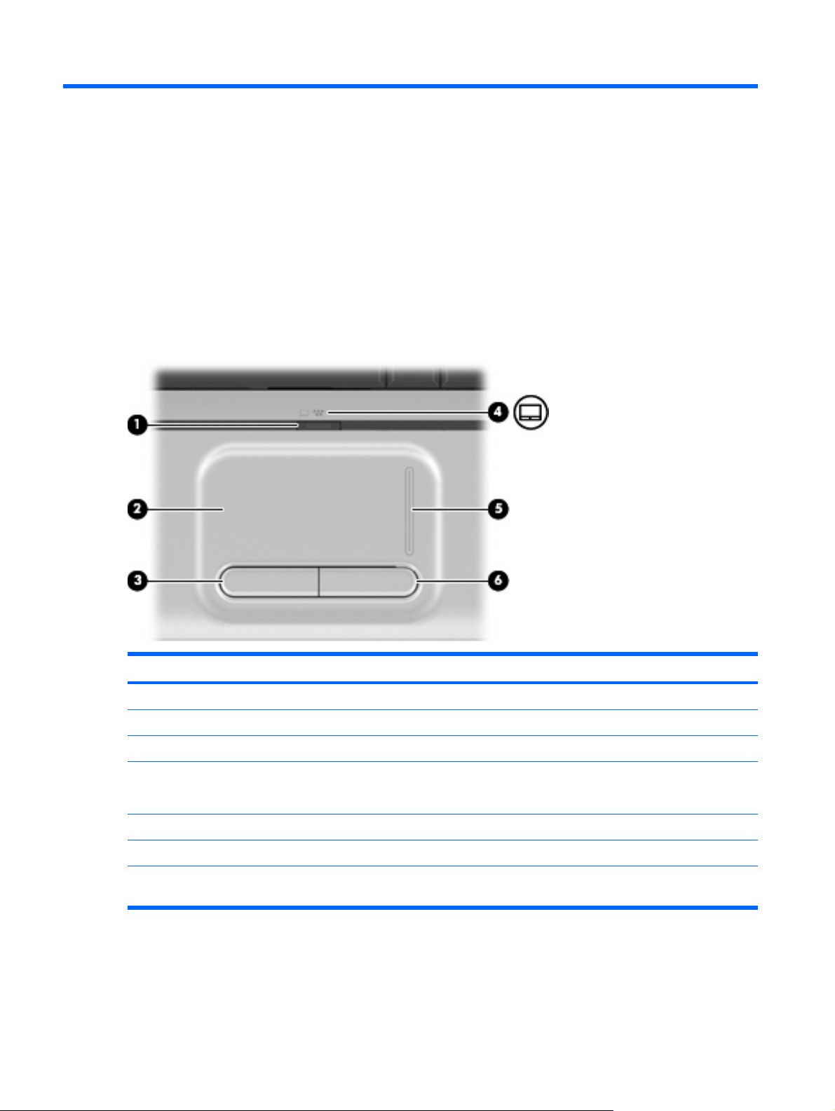
TouchPad
Component Description
(1) TouchPad on/off button Enables/disables the TouchPad.
(2) TouchPad* Moves the pointer and selects or activates items on the screen.
(3) Left TouchPad button* Functions like the left button on an external mouse.
(4) TouchPad light
(5) TouchPad scroll zone* Scrolls up or down.
(6) Right TouchPad button* Functions like the right button on an external mouse.
*This table describes factory settings. To view or change pointing device preferences, select Start > Control Panel > Hardware
and Sound > Mouse.
4 Chapter 2 External component identification
White: TouchPad is enabled.
●
Amber: TouchPad is disabled.
●
Page 13
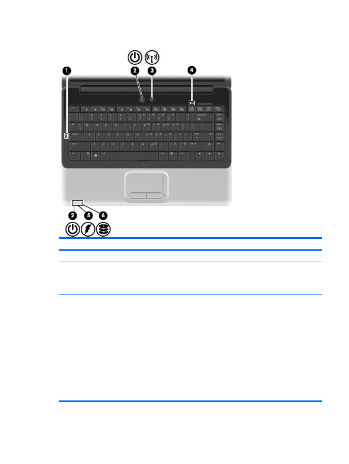
Lights
Component Description
(1) Caps lock light On: Caps lock is on.
(2) Power lights (2)*
(3) Wireless light
(4) Num lock light On: Num lock is on or the embedded numeric keypad is enabled.
(5) Battery light
On: The computer is on.
●
Blinking: The computer is in the Sleep state.
●
Off: The computer is off or in Hibernation.
●
Blue: An integrated wireless device, such as a wireless local
●
area network (WLAN) device and/or a Bluetooth® device, is
on.
Amber: All wireless devices are off.
●
On: A battery is charging.
●
Blinking: A battery that is the only available power source has
●
reached a low battery level or a critical battery level.
Off: If the computer is plugged into an external power source,
●
the light is turned off when all batteries in the computer are
fully charged. If the computer is not plugged into an external
power source, the light stays off until the battery reaches a
low battery level.
Top components 5
Page 14

Component Description
(6) Drive light
*The 2 power lights display the same information. The light on the power button is visible only when the computer is open. The
power light on the front of the computer is visible whether the computer is open or closed.
Blinking: The hard drive or optical drive is being accessed.
●
On: HP ProtectSmart Hard Drive Protection has temporarily
●
parked the internal hard drive.
6 Chapter 2 External component identification
Page 15
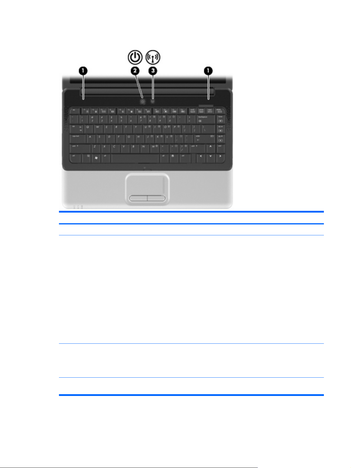
Buttons and speakers
Component Description
(1) Speakers (2) Produce sound.
(2) Power button*
(3) Wireless button Turns the wireless feature on or off but does not establish a
*This table describes factory settings. For information about changing factory settings, refer to the user guides located in Help
and Support.
When the computer is off, press the button to turn on the
●
computer.
When the computer is on, briefly press the button to initiate
●
Sleep.
When the computer is in the Sleep state, briefly press the
●
button to exit Sleep.
When the computer is in Hibernation, briefly press the button
●
to exit Hibernation.
If the computer has stopped responding and Windows® shutdown
procedures are ineffective, press and hold the power button for at
least 5 seconds to turn off the computer.
To learn more about your power settings, select Start > Control
Panel > System and Maintenance > Power Options.
wireless connection.
NOTE: A wireless network must be set up in order to establish a
wireless connection.
Top components 7
Page 16

Keys
NOTE: Your computer may look slightly different from the illustration in this section.
Component Description
(1) esc key Displays system information when pressed in combination with
the fn key.
(2) fn key Executes frequently used system functions when pressed in
(3) Windows logo key Displays the Windows Start menu.
(4) Function keys Execute frequently used system functions when pressed in
(5) Embedded numeric keypad keys Can be used like the keys on an external numeric keypad.
(6) Windows applications key Displays a shortcut menu for items beneath the pointer.
(7) Navigation keys (home, pg up, pg down) Execute volume mute, volume up, or volume down when pressed
combination with a function key or the esc key.
combination with the fn key.
in combination with the fn key.
8 Chapter 2 External component identification
Page 17
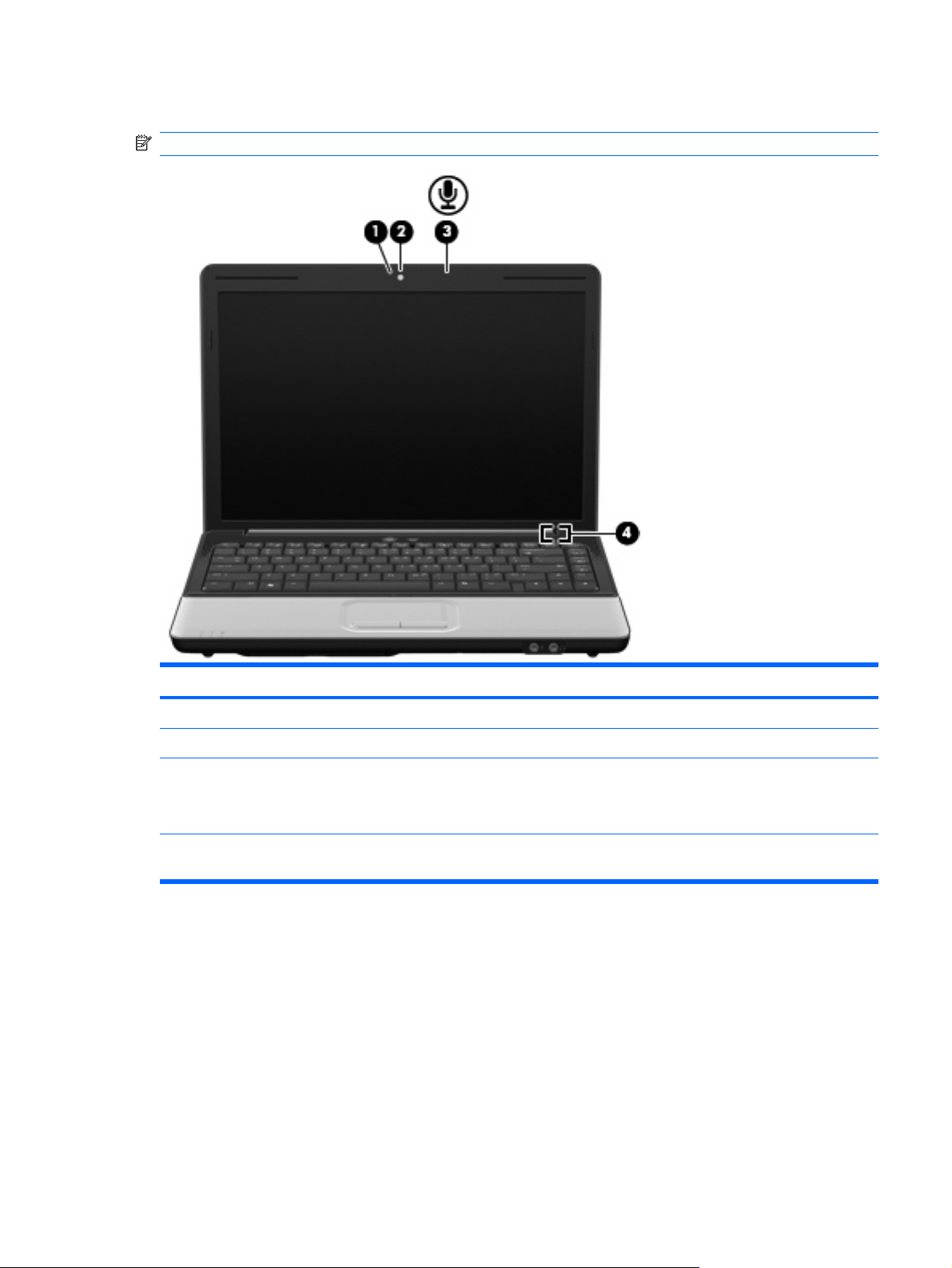
Display
NOTE: Your computer may look slightly different from the illustration in this section.
Component Description
(1) Integrated webcam light On: The integrated webcam is in use.
(2) Integrated webcam Records video and captures still photographs.
(3) Internal microphone Records sound.
NOTE: If there is a microphone icon next to each microphone
opening, your computer has internal microphones.
(4) Internal display switch Turns off the display if the display is closed while the computer is
turned on.
Top components 9
Page 18
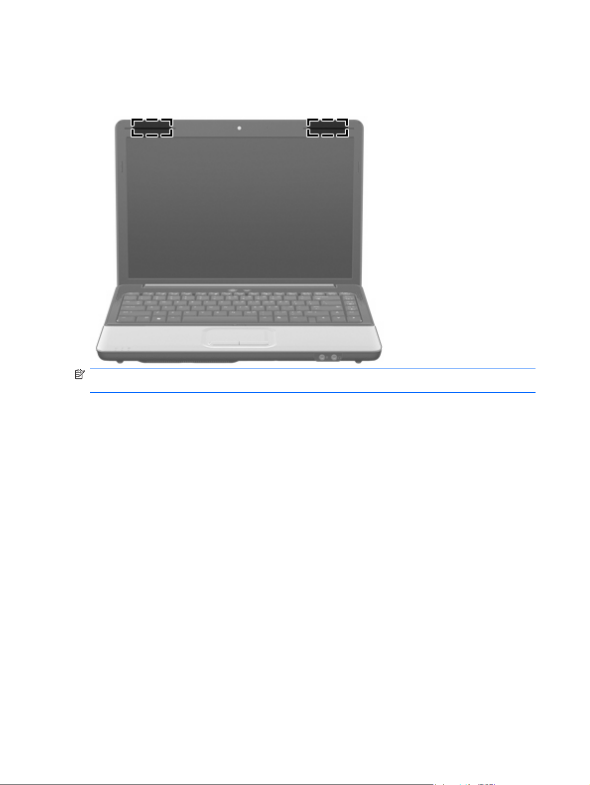
Wireless antennas
On select computer models, at least 2 antennas send and receive signals from one or more wireless
devices.
NOTE: The antennas are not visible from the outside of the computer. For optimal transmission, keep
the areas immediately around the antennas free from obstructions.
To see wireless regulatory notices, refer to the section of the Regulatory, Safety and Environmental
Notices that applies to your country or region. These notices are located in Help and Support.
10 Chapter 2 External component identification
Page 19
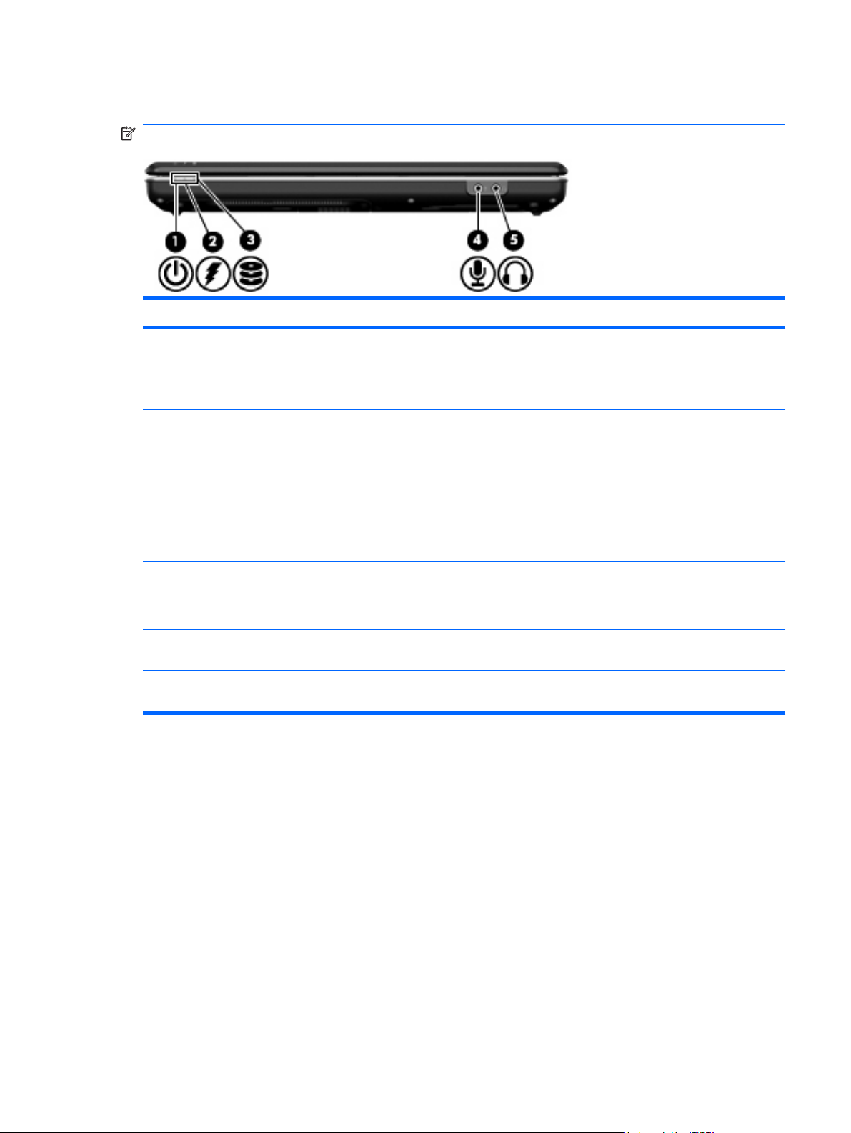
Front components
NOTE: Your computer may look slightly different from the illustration in this section.
Component Description
(1) Power light
(2) Battery light
(3) Drive light
(4) Audio-in (microphone) jack Connects an optional computer headset microphone, stereo array
(5) Audio-out (headphone) jack Produces sound when connected to optional powered stereo
On: The computer is on.
●
Blinking: The computer is in the Sleep state.
●
Off: The computer is off or in Hibernation.
●
On: A battery is charging.
●
Blinking: A battery that is the only available power source has
●
reached a low battery level or a critical battery level.
Off: If the computer is plugged into an external power source,
●
the light is turned off when all batteries in the computer are
fully charged. If the computer is not plugged into an external
power source, the light stays off until the battery reaches a low
battery level.
Blinking: The hard drive or optical drive is being accessed.
●
On: HP ProtectSmart Hard Drive Protection has temporarily
●
parked the internal hard drive.
microphone, or monaural microphone.
speakers, headphones, ear buds, a headset, or television audio.
Front components 11
Page 20
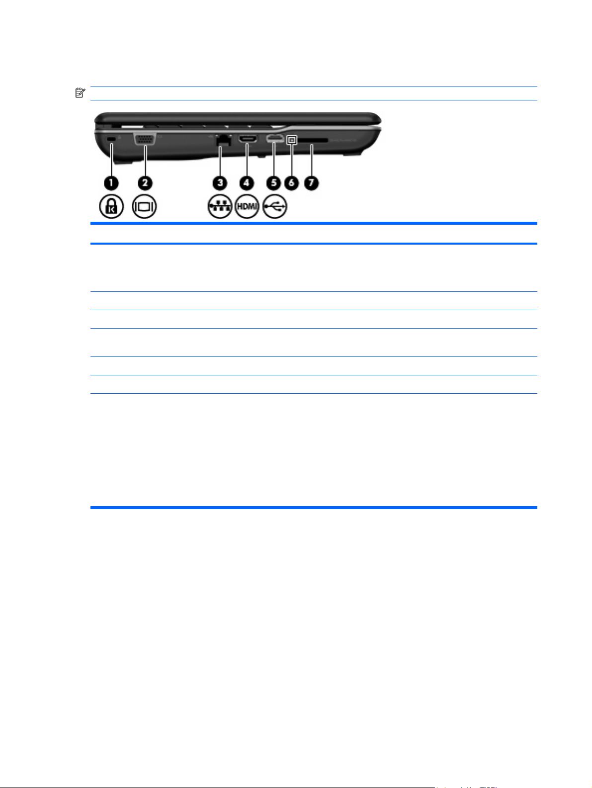
Left-side components
NOTE: Your computer may look slightly different from the illustration in this section.
Component Description
(1) Security cable slot Attaches an optional security cable to the computer.
(2) External monitor port Connects an external VGA monitor or projector.
(3) RJ-45 (network) jack Connects a network cable.
(4) HDMI port Connects an optional video or audio device, such as a high-
NOTE: The security cable is designed to act as a deterrent, but
it may not prevent the computer from being mishandled or stolen.
definition television, or any compatible digital or audio component.
(5) USB port Connects an optional USB device.
(6) Digital Media Slot light On: A digital card is being accessed.
(7) Digital Media Slot Supports the following optional digital card formats:
Memory Stick (MS)
●
Memory Stick Pro (MSP)
●
MultiMedia Card (MMC)
●
Secure Digital (SD) Memory Card
●
xD-Picture Card (XD)
●
12 Chapter 2 External component identification
Page 21
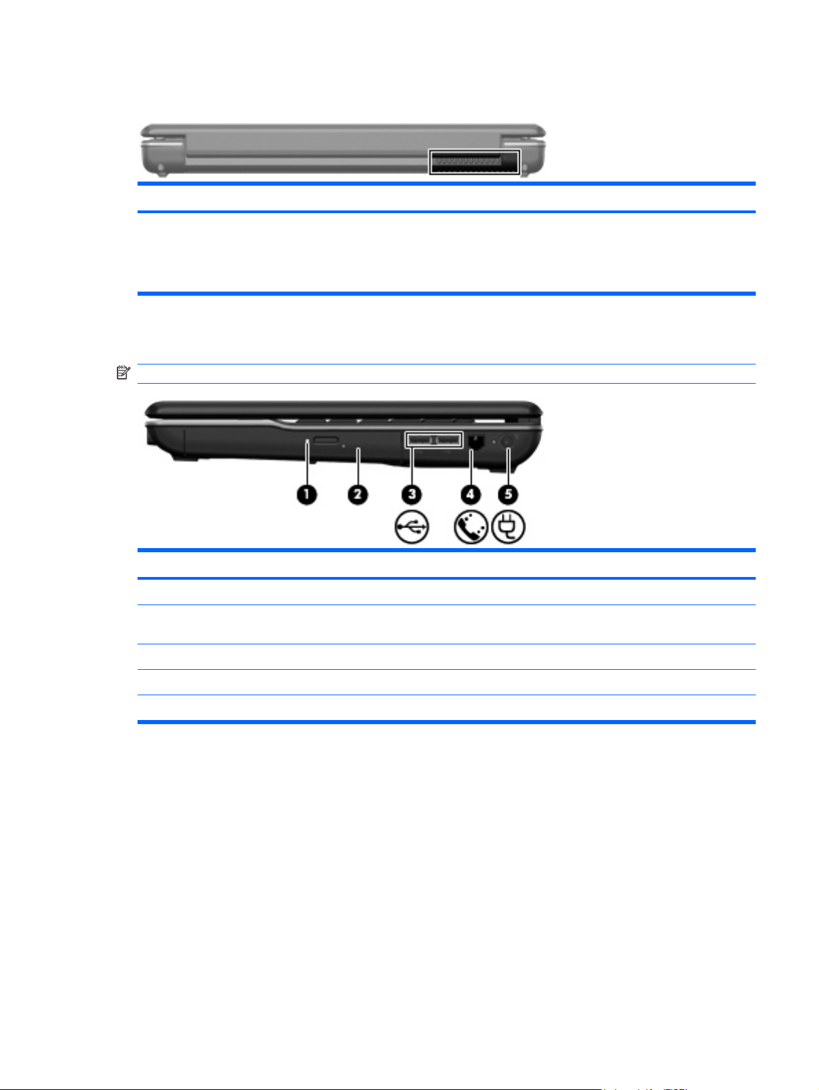
Rear component
Component Description
Vent Enables airflow to cool internal components.
Right-side components
NOTE: Your computer may look slightly different from the illustration in this section.
NOTE: The computer fan starts up automatically to cool internal
components and prevent overheating. It is normal for the internal fan to
cycle on and off during routine operation.
Component Description
(1) Optical drive light Blinking: The optical drive is being accessed.
(2) Optical drive Reads optical discs and, on select models, also writes to optical
discs.
(3) USB ports (2) Connect optional USB devices.
(4) RJ-11 (modem) jack (select models only) Connects a modem cable.
(5) Power connector Connects an AC adapter.
Rear component 13
Page 22
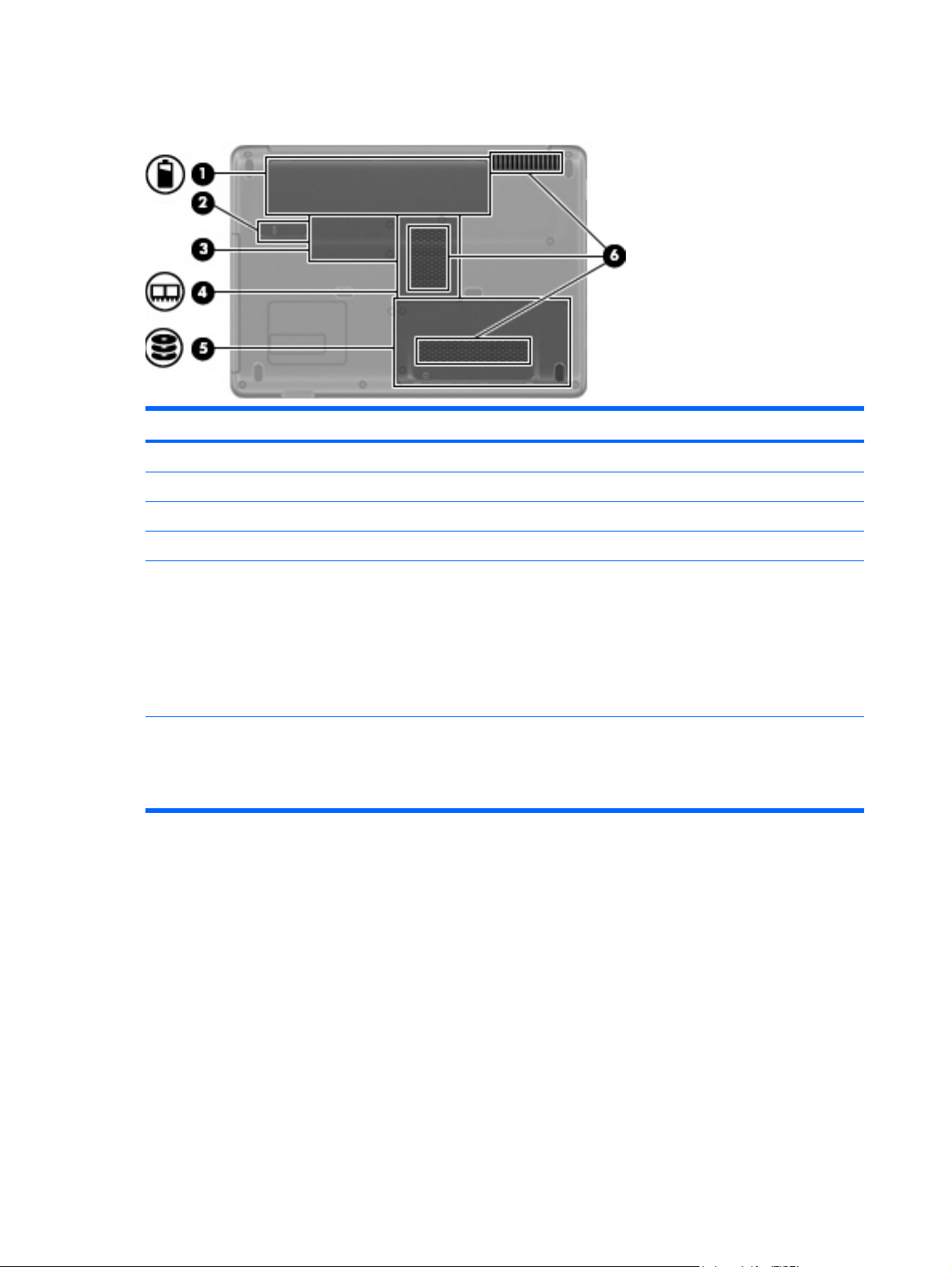
Bottom components
Component Description
(1) Battery bay Holds the battery.
(2) Battery release latch Releases the battery from the battery bay.
(3) RTC battery compartment Holds the RTC battery.
(4) Memory module compartment Contains the 2 memory module slots.
(5) Hard drive and WLAN module compartment Holds the hard drive and the wireless LAN (WLAN) device.
CAUTION: To prevent an unresponsive system, replace the
wireless module only with a wireless module authorized for use in
the computer by the governmental agency that regulates wireless
devices in your country or region. If you replace the module and
then receive a warning message, remove the module to restore
computer functionality, and then contact technical support through
Help and Support.
(6) Vents (3) Enable airflow to cool internal components.
NOTE: The computer fan starts up automatically to cool internal
components and prevent overheating. It is normal for the internal
fan to cycle on and off during routine operation.
14 Chapter 2 External component identification
Page 23
3 Illustrated part numbers catalog
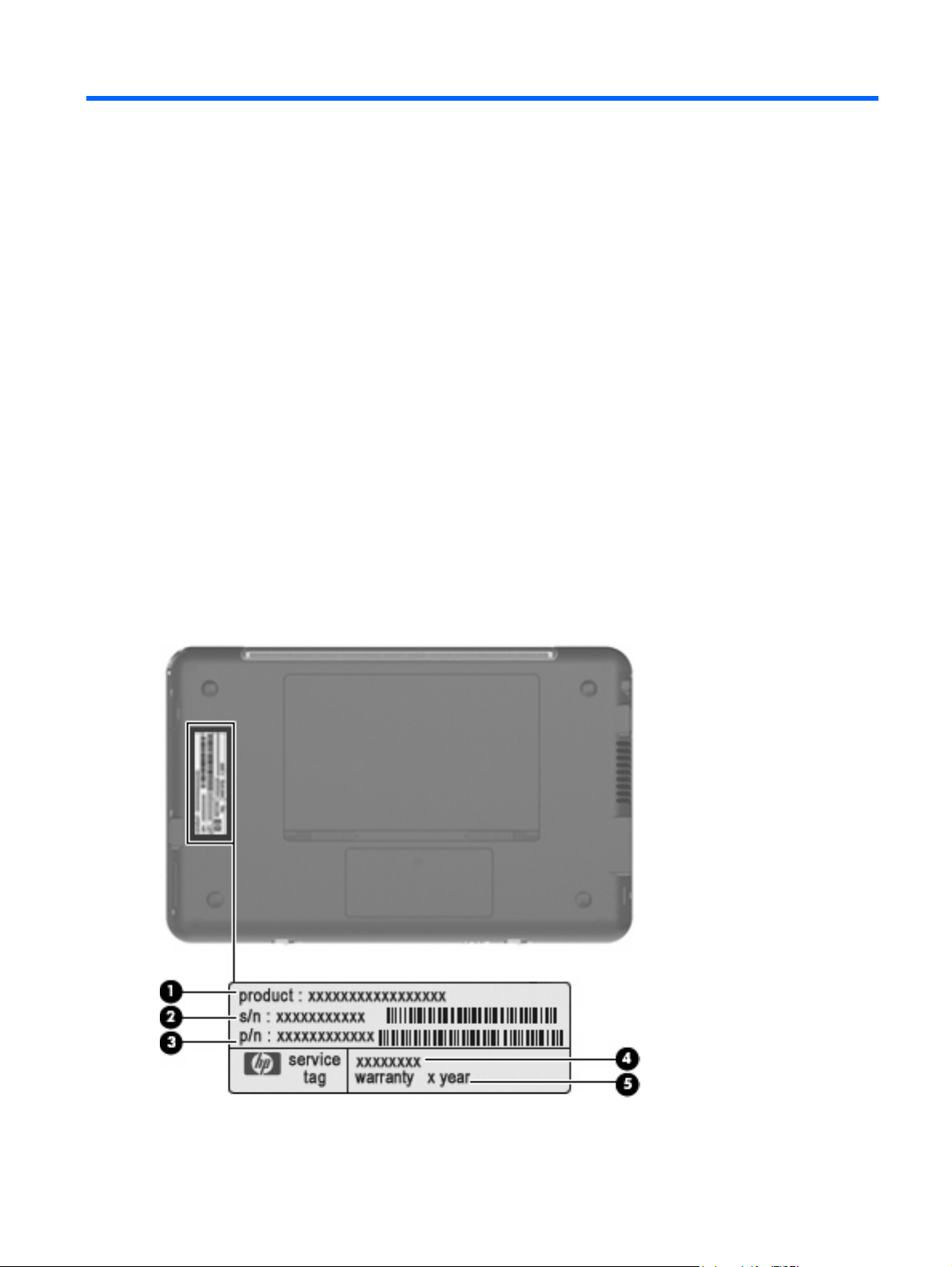
Service tag
When ordering parts or requesting information, provide the computer serial number and model
description provided on the service tag.
(1) Product name: This is the product name affixed to the front of the device.
(2) Serial number (s/n): This is an alphanumeric identifier that is unique to each product.
(3) Part number/Product number (p/n): This number provides specific information about the product's
hardware components. The part number helps a service technician to determine what components and
parts are needed.
(4) Model description: This is the alphanumeric identifier used to locate documents, drivers, and support
for the device.
(5) Warranty period: This number describes the duration of the warranty period for the device.
Service tag 15
Page 24
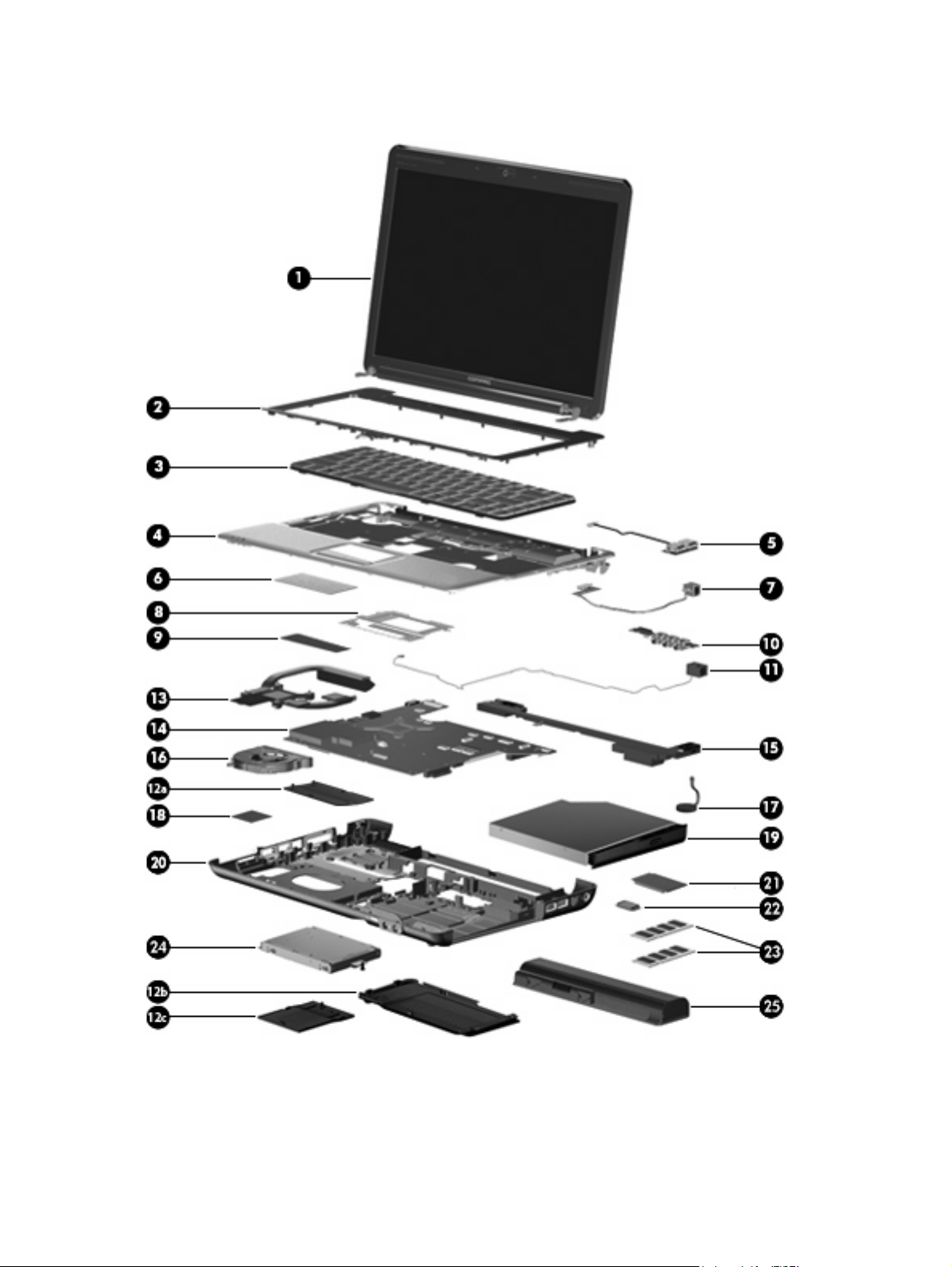
Computer major components
16 Chapter 3 Illustrated part numbers catalog
Page 25

Item Description Spare part number
(1) 14.1-in, WXGA BrightView display assembly
NOTE: See
internal component spare part information.
(2) Keyboard cover (includes power button board and cable) 487299-001
Power button board (not illustrated) 492249-001
(3) Keyboard
Taiwan 486904-AB1
Thailand 486904-281
The United States 486904-001
(4) Top cover 487300-001
(5) USB board 486842-001
USB board cable (not illustrated) 486843-001
(6) TouchPad 494960-001
(7) Power connector cable (includes power connector and cable) 486864-001
(8) TouchPad bracket 494962-001
(9) TouchPad button board 494965-001
South Korea 486904-AD1
Display assembly componentson page 20 for more display assembly
487281-001
(10) Audio board (includes audio connectors and audio board cable) 487344-001
Audio board cable (not illustrated) 486841-001
(11) Modem module (select models only)
For use in all countries and regions except Australia and New Zealand 461749-001
For use in Australia and New Zealand 461749-011
Modem module cable (includes RJ-11 connector, not illustrated) 494981-001
Plastics Kit 486862-001
(12a) Real time clock (RTC) battery compartment cover
(12b) Hard drive cover
(12c) Memory module compartment cover
(13) Heat sink (includes thermal material) 530614-001
(14) System board (includes thermal material) 532327-001
(15) Speaker assembly 486865-001
(16) Fan 486844-001
(17) RTC battery (includes two-sided tape) 486835-001
(18) WLAN module
Intel Wi-Fi Link 5100 802.11a/b/g/n WLAN module for use in all countries and regions
Computer major components 17
480985-001
Page 26

Item Description Spare part number
Intel Wi-Fi Link 5100 802.11a/b/g WLAN module for use in all countries and regions 482957-001
Broadcom 4312 802.11 WLAN b/g module for use in Canada, the Cayman Islands, Guam,
Puerto Rico, Trinidad and Tobago, the U.S. Virgin Islands, and the United States
Broadcom 4322 802.11 a/b/g/n WLAN module for use in Afghanistan, Albania, Algeria,
Andorra, Angola, Antigua and Barbuda, Argentina, Armenia, Australia, Austria,
Azerbaijan, Bahamas, Bahrain, Bangladesh, Barbados, Belarus, Belgium, Belize, Benin,
Bhutan, Bolivia, Bosnia and Herzegovina, Botswana, Brazil, Brunei, Bulgaria, Burkina,
Faso Burundi, Cambodia, Cameroon, Cape Verde, Central African Republic, Chad, Chile,
People's Republic of China, Colombia, Comoros, Congo, Costa Rica, Croatia, Cyprus,
Czech Republic, Zaire, Denmark, Djibouti, Dominica, Dominican Republic, Ecuador,
Egypt, El Salvador, Equatorial Guinea, Eritrea, Estonia, Ethiopia, Fiji, Finland, France,
Gabon, Gambia, Georgia, Germany, Ghana, Gibraltar, Greece, Grenada, Guatemala,
Guinea, Guinea-Bissau, Guyana, Haiti, Honduras, Hong Kong, Hungary, Iceland, India,
Indonesia, Ireland, Israel, Italy, Ivory Coast, Jamaica, Japan, Jordan, Kazakhstan, Kenya,
Kiribati, Kuwait, Kyrgyzstan, Laos, Latvia, Lebanon, Lesotho, Liberia, Martinique, British
Virgin Islands, French Guiana, Guadeloupe, Nether Antilles, Aruba, Bermuda, Syria,
Liechtenstein, Lithuania, Luxembourg, Macedonia, Madagascar, Malawi, Malaysia,
Maldives, Mali, Malta, Marshall Islands, Mauritania, Mauritius, Mexico, Micronesia,
Monaco, Mongolia, Montenegro, Morocco, Mozambique, Namibia, Nauru, Nepal,
Netherlands, New Zealand, Nicaragua, Niger, Nigeria, Norway, Oman, Pakistan, Palau,
Panama, Papua New Guinea, Paraguay, Peru, Philippines, Poland, Portugal, Qatar,
Republic of Moldova, Romania, Russia, Rwanda, Samoa, San Marino, Sao Tome and
Principe, Saudi Arabia, Senegal, Serbia, Seychelles, Sierra Leone, Singapore, Slovakia,
Slovenia, Solomon Islands, Somalia, South Africa, South Korea, Spain, Sri Lanka, St. Kitts
and Nevis, St. Lucia, St. Vincent and Grenadines, Suriname, Swaziland, Sweden,
Switzerland, Taiwan, Tajikistan, Tanzania, Thailand, East Timor, Togo, Tonga, Trinidad
and Tobago, Tunisia, Turkey, Turkmenistan, Tuvalu, Uganda, Ukraine, United Arab
Emirates, The United Kingdom, Uruguay, Uzbekistan, Vanuatu, Venezuela, Vietnam,
Yemen, Zambia, and Zimbabwe
459263-001
487330-002
(19) Optical drive (includes bezel)
(20) Base enclosure
For use in computer models with a modem module 492248-001
For use in computer models without a modem module 487359-001
(21) Processor (includes thermal material)
DVD±RW and CD-RW SuperMulti Double-Layer Combo Drive with LightScribe
●
Blu-ray ROM with LightScribe DVD±RW SuperMulti Double-Layer Drive
●
Intel Core2 Duo mobile processor:
T9550 (2.66 GHz, 6-MB L2 cache)
●
P8700 (2.53 GHz, 3-MB L2 cache)
●
P8600 (2.40 GHz, 3-MB L2 cache)
●
P8400 (2.26 GHz, 3-MB L2 cache)
●
P7450 (2.13 GHz, 3-MB L2 cache)
●
T5800 (2.06 GHz, 2-MB L2 cache)
●
T6400 (2.00 GHz, 2-MB L2 cache)
●
T6600 (2.20 GHz, 2-MB L2 cache)
●
532342-001
532341-001
507953-001
507960-001
507963-001
507964-001
507965-001
515040-001
513592-001
513593-001
Intel Pentium processor for mobile:
18 Chapter 3 Illustrated part numbers catalog
Page 27

Item Description Spare part number
(22) Bluetooth module 483113-001
Bluetooth module cable (not illustrated) 488130-001
(23) Memory modules (PC2-6400, 800-MHz, DDR2)
(24) Hard drive (includes hard drive bracket)
Hard Drive Hardware Kit (contains screws and hard drive bracket; not illustrated) 482158-001
(25) Battery, 6-cell Li-Ion (2.2-Ah, 47-Wh) 487296-001
T3400 (2.16 GHz, 1-MB cache)
●
T4200 (2.00 GHz, 1-MB cache)
●
1024 MB
●
2048 MB
●
160 GB, 5400 rpm
●
250 GB, 5400 rpm
●
320 GB, 5400 rpm
●
500 GB, 5400 rpm
●
509549-001
513599-001
532331-001
532332-001
532337-001
532338-001
532339-001
532340-001
Computer major components 19
Page 28
Display assembly components
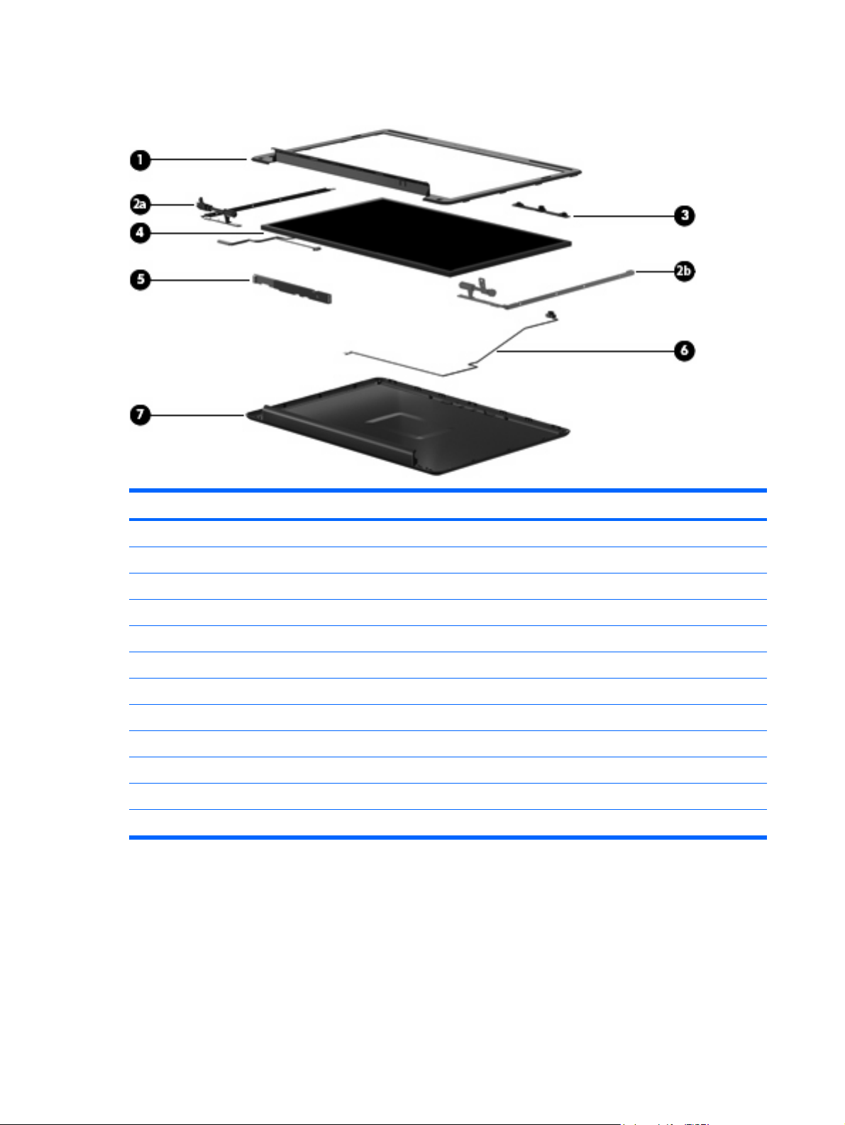
Item Description Spare part number
(1) Display bezel 487286-001
Display Hinge Kit 486737-001
(2a) Left/right display panel brackets
(2b) Left/right display hinges
(3) Camera module 487287-001
(4) 14.1-in, WXGA TFT BrightView display panel (includes display panel cable) 487279-001
(5) Display inverter (includes Mylar™ shield) 486736-001
(6) Microphone module and cable 517629-001
(7) Display enclosure 487284-001
Display cable (not illustrated) 486735-001
Display Screw Kit (not illustrated) 486730-001
Display Rubber Kit (not illustrated; includes rubber screw covers and LCD rubber pads) 487283-001
20 Chapter 3 Illustrated part numbers catalog
Page 29
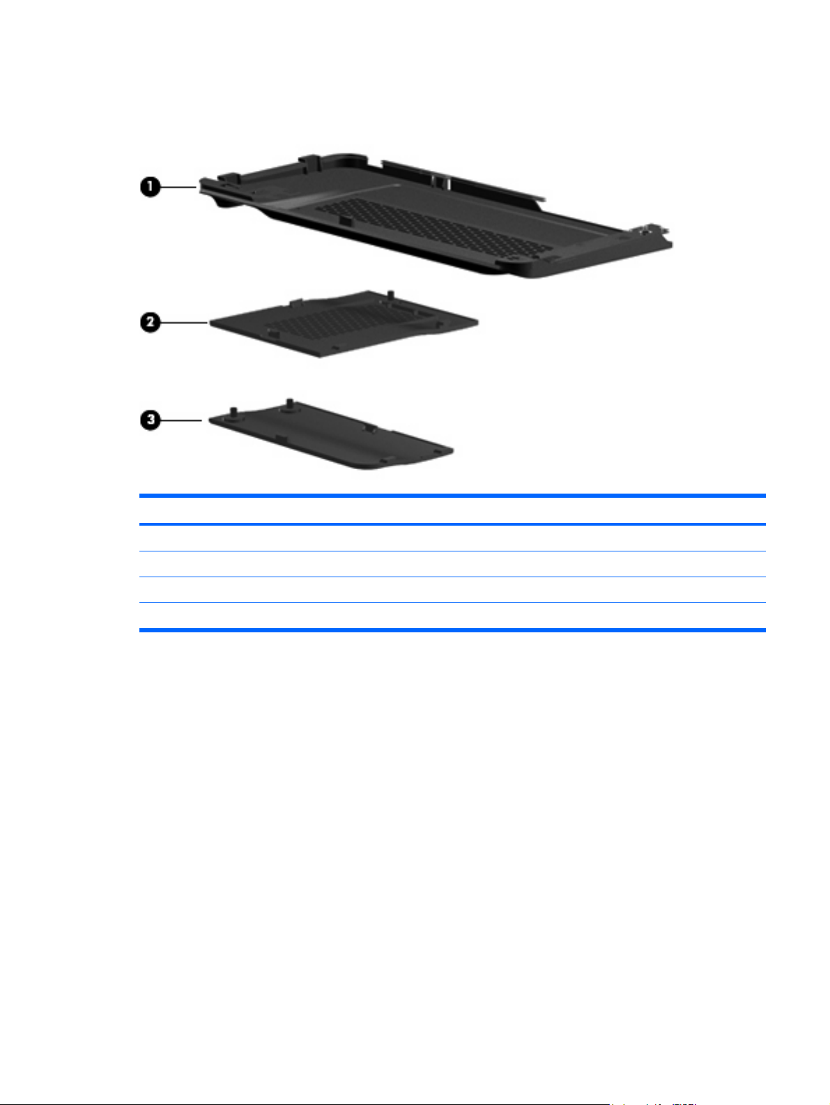
Plastics Kit
Item Description Spare part number
Plastics Kit 486862-001
(1) Hard drive cover (includes 2 screws)
(2) Memory module compartment cover (includes 1 screw)
(3) RTC battery compartment cover
Plastics Kit 21
Page 30
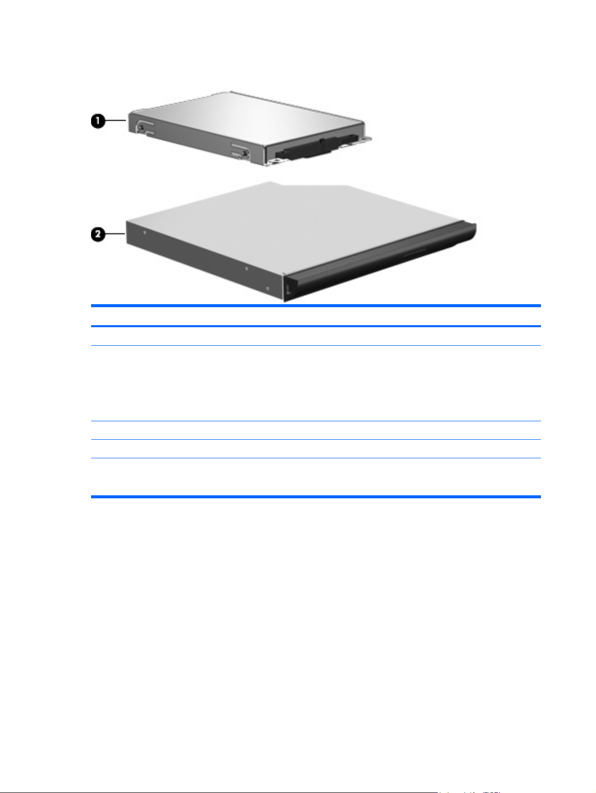
Mass storage devices
Item Description Spare part number
(1) Hard drive (includes hard drive bracket)
Hard Drive Hardware Kit (contains screws and hard drive bracket; not illustrated) 482158-001
(2) Optical drive (includes bezel)
160 GB, 5400 rpm
●
250 GB, 5400 rpm
●
320 GB, 5400 rpm
●
500 GB, 5400 rpm
●
DVD±RW and CD-RW SuperMulti Double-Layer Combo Drive with LightScribe
●
Blu-ray ROM with LightScribe DVD±RW SuperMulti Double-Layer Drive
●
532337-001
532338-001
532339-001
532340-001
532342-001
532341-001
22 Chapter 3 Illustrated part numbers catalog
Page 31

Miscellaneous parts
Description Spare part number
90-W PFC AC adapter 463955-001
Internal display switch module 489862-001
Power cord:
Australia
Brazil 490371-201
India 490371-D61
North America 490371-001
South Korea 490371-AD1
Taiwan 490371-AB1
The People's Republic of China 490371-AA1
The United Kingdom and Singapore 490371-031
Screw Kit
Phillips PM2.0×2.0 broadhead screws
●
Phillips PM2.0×3.0 screws
●
Phillips PM2.0×4.0 screws
●
Phillips PM2.0×10.0 captive screws
●
Phillips PM2.5×3.0 screws
●
Phillips PM2.5×4.0 screws
●
Phillips PM2.5×5.0 screws
●
490371-011
487298-001
Phillips PM2.5×5.0 captive screws
●
Phillips PM2.5×6.0 screws
●
Phillips PM2.5×7.0 captive screws
●
Phillips PM2.5×10.0 screws
●
Phillips PM2.5×18.0 screws
●
Phillips PM3.0×3.0 screws
●
Rubber Kit (includes 6 rubber computer feet) 486863-001
Miscellaneous parts 23
Page 32

Sequential part number listing
Spare part
number
459263-001 Broadcom 4312 802.11 WLAN b/g module for use in Canada, the Cayman Islands, Guam, Puerto Rico,
461749-001 Modem module for use in all countries and regions except Australia and New Zealand (select models only)
461749-011 Modem module for use in Australia and New Zealand (select models only)
463955-001 90-W PFC AC adapter
480985-001 Intel Wi-Fi Link 5100 802.11a/b/g/n WLAN module for use in all countries and regions
482158-001 Hard Drive Hardware Kit (contains screws and hard drive bracket)
482957-001 Intel Wi-Fi Link 5100 802.11a/b/g WLAN module for use in all countries and regions
483113-001 Bluetooth module
486730-001 Display Screw Kit
486735-001 Display assembly cable
486736-001 Display inverter (includes Mylar shield and bracket)
486737-001 Display Hinge Kit (includes left and right display hinges and display switch module)
486835-001 RTC battery (includes two-sided tape)
486841-001 Audio board cable
Description
Trinidad and Tobago, the U.S. Virgin Islands, and the United States
486842-001 USB board
486843-001 USB board cable
486844-001 Fan
486862-001 Plastics Kit (see Plastics Kit on page 21 for more information)
486863-001 Rubber Kit (includes 6 rubber computer feet)
486864-001 Power connector cable (includes power connector)
486865-001 Speaker assembly
488130-001 Bluetooth module cable
486904-001 Keyboard for use in the United States
486904-281 Keyboard for use in Thailand
486904-AB1 Keyboard for use in Taiwan
486904-AD1 Keyboard for use in South Korea
487281-001 14.1-in, WXGA TFT BrightView display panel (includes display panel cable)
487283-001 Display Rubber Kit (includes rubber screw covers and LCD rubber pads)
487284-001 Display enclosure
487286-001 Display bezel
487287-001 Camera module
24 Chapter 3 Illustrated part numbers catalog
Page 33

Spare part
number
487298-001 Screw Kit
487299-001 Keyboard cover (includes power button board and cable)
487300-001 Top cover
Description
487330-002 Broadcom 4322 802.11 a/b/g/n WLAN module for use in Afghanistan, Albania, Algeria, Andorra, Angola,
487344-001 Audio board (includes audio connectors and audio board cable)
487359-001 Base enclosure for use only in computer models without a modem module (includes wireless on/off switch)
489862-001 Internal display switch module
490371-001 Power cord for use in the United States
Antigua and Barbuda, Argentina, Armenia, Australia, Austria, Azerbaijan, Bahamas, Bahrain, Bangladesh,
Barbados, Belarus, Belgium, Belize, Benin, Bhutan, Bolivia, Bosnia and Herzegovina, Botswana, Brazil,
Brunei, Bulgaria, Burkina, Faso Burundi, Cambodia, Cameroon, Cape Verde, Central African Republic, Chad,
Chile, People's Republic of China, Colombia, Comoros, Congo, Costa Rica, Croatia, Cyprus, Czech Republic,
Zaire, Denmark, Djibouti, Dominica, Dominican Republic, Ecuador, Egypt, El Salvador, Equatorial Guinea,
Eritrea, Estonia, Ethiopia, Fiji, Finland, France, Gabon, Gambia, Georgia, Germany, Ghana, Gibraltar, Greece,
Grenada, Guatemala, Guinea, Guinea-Bissau, Guyana, Haiti, Honduras, Hong Kong, Hungary, Iceland, India,
Indonesia, Ireland, Israel, Italy, Ivory Coast, Jamaica, Japan, Jordan, Kazakhstan, Kenya, Kiribati, Kuwait,
Kyrgyzstan, Laos, Latvia, Lebanon, Lesotho, Liberia, Martinique, British Virgin Islands, French Guiana,
Guadeloupe, Nether Antilles, Aruba, Bermuda, Syria, Liechtenstein, Lithuania, Luxembourg, Macedonia,
Madagascar, Malawi, Malaysia, Maldives, Mali, Malta, Marshall Islands, Mauritania, Mauritius, Mexico,
Micronesia, Monaco, Mongolia, Montenegro, Morocco, Mozambique, Namibia, Nauru, Nepal, Netherlands,
New Zealand, Nicaragua, Niger, Nigeria, Norway, Oman, Pakistan, Palau, Panama, Papua New Guinea,
Paraguay, Peru, Philippines, Poland, Portugal, Qatar, Republic of Moldova, Romania, Russia, Rwanda,
Samoa, San Marino, Sao Tome and Principe, Saudi Arabia, Senegal, Serbia, Seychelles, Sierra Leone,
Singapore, Slovakia, Slovenia, Solomon Islands, Somalia, South Africa, South Korea, Spain, Sri Lanka, St.
Kitts and Nevis, St. Lucia, St. Vincent and Grenadines, Suriname, Swaziland, Sweden, Switzerland, Taiwan,
Tajikistan, Tanzania, Thailand, East Timor, Togo, Tonga, Trinidad and Tobago, Tunisia, Turkey,
Turkmenistan, Tuvalu, Uganda, Ukraine, United Arab Emirates, The United Kingdom, Uruguay, Uzbekistan,
Vanuatu, Venezuela, Vietnam, Yemen, Zambia, and Zimbabwe
490371-011 Power cord for use in Australia
490371-031 Power cord for use in the United Kingdom and Singapore
490371-201 Power cord for use in Brazil
490371-281 Power cord for use in Thailand
490371-AA1 Power cord for use in the People's Republic of China
490371-AB1 Power cord for use in Taiwan
490371-AD1 Power cord for use in South Korea
490371-D61 Power cord for use in India
491832-001 Intel T7350 Core2 Duo mobile processor (2.00 GHz, 3-MB L2 cache)
492248-001 Base enclosure for use only in computer models with a modem module (select models only)
492249-001 Power button board
494960-001 TouchPad
494962-001 TouchPad bracket
494965-001 TouchPad button board
494981-001 Modem module cable (includes RJ-11 connector)
Sequential part number listing 25
Page 34

Spare part
number
504781-001 320 GB, 5400-rpm hard drive (includes hard drive bracket)
507953-001 Intel T9550 Core2 Duo mobile processor (2.66 GHz, 6-MB L2 cache)
507960-001 Intel P8700 Core2 Duo mobile processor (2.53 GHz, 3-MB L2 cache)
507963-001 Intel P8600 Core2 Duo mobile processor (2.40 GHz, 3-MB L2 cache)
507964-001 Intel P8400 Core2 Duo mobile processor (2.26 GHz, 3-MB L2 cache)
507965-001 Intel P7450 Core2 Duo mobile processor (2.13 GHz, 3-MB L2 cache)
509549-001 Intel T3400 Pentium processor for mobile (2.16 GHz, 1-MB L2 cache)
513592-001 Intel T6400 Core2 Duo mobile processor (2.00 GHz, 2-MB L2 cache)
513593-001 Intel T6600 Core2 Duo mobile processor (2.20 GHz, 2-MB L2 cache)
513599-001 Intel T4200 Pentium processor for mobile (2.00 GHz, 1-MB L2 cache)
515040-001 Intel T5800 Core2 Duo mobile processor (2.06 GHz, 2-MB L2 cache)
517629-001 Microphone module and cable
530614-001 Heat sink (includes thermal material)
532327-001 System board (includes thermal material)
532331-001 1024-MB memory module (PC2-6400, 800-MHz, DDR2)
Description
532332-001 2048-MB memory module (PC2-6400, 800-MHz, DDR2)
532337-001 160 GB, 5400-rpm hard drive (includes bracket)
532338-001 250 GB, 5400-rpm hard drive (includes bracket)
532339-001 320 GB, 5400-rpm hard drive (includes bracket)
532340-001 500 GB, 5400-rpm hard drive (includes bracket)
532341-001 Blu-ray ROM with LightScribe DVD±RW SuperMulti Double-Layer Drive (includes bezel)
532342-001 DVD±RW and CD-RW SuperMulti Double-Layer Combo Drive with LightScribe (includes bezel)
536436-001 6-cell Li-Ion battery (2.2-Ah, 47-Wh)
26 Chapter 3 Illustrated part numbers catalog
Page 35

4 Removal and replacement procedures
Preliminary replacement requirements
Tools required
You will need the following tools to complete the removal and replacement procedures:
Flat-bladed screwdriver
●
Magnetic screwdriver
●
Phillips P0 and P1 screwdrivers
●
Service considerations
The following sections include some of the considerations that you must keep in mind during
disassembly and assembly procedures.
NOTE: As you remove each subassembly from the computer, place the subassembly (and all
accompanying screws) away from the work area to prevent damage.
Plastic parts
CAUTION: Using excessive force during disassembly and reassembly can damage plastic parts. Use
care when handling the plastic parts. Apply pressure only at the points designated in the maintenance
instructions.
Preliminary replacement requirements 27
Page 36

Cables and connectors
CAUTION: When servicing the computer, be sure that cables are placed in their proper locations
during the reassembly process. Improper cable placement can damage the computer.
Cables must be handled with extreme care to avoid damage. Apply only the tension required to unseat
or seat the cables during removal and insertion. Handle cables by the connector whenever possible. In
all cases, avoid bending, twisting, or tearing cables. Be sure that cables are routed in such a way that
they cannot be caught or snagged by parts being removed or replaced. Handle flex cables with extreme
care; these cables tear easily.
Drive handling
CAUTION: Drives are fragile components that must be handled with care. To prevent damage to the
computer, damage to a drive, or loss of information, observe these precautions:
Before removing or inserting a hard drive, shut down the computer. If you are unsure whether the
computer is off or in Hibernation, turn the computer on, and then shut it down through the operating
system.
Before handling a drive, be sure that you are discharged of static electricity. While handling a drive,
avoid touching the connector.
Before removing a diskette drive or optical drive, be sure that a diskette or disc is not in the drive and
be sure that the optical drive tray is closed.
Handle drives on surfaces covered with at least one inch of shock-proof foam.
Avoid dropping drives from any height onto any surface.
After removing a hard drive, an optical drive, or a diskette drive, place it in a static-proof bag.
Avoid exposing a hard drive to products that have magnetic fields, such as monitors or speakers.
Avoid exposing a drive to temperature extremes or liquids.
If a drive must be mailed, place the drive in a bubble pack mailer or other suitable form of protective
packaging and label the package “FRAGILE.”
28 Chapter 4 Removal and replacement procedures
Page 37

Grounding guidelines
Electrostatic discharge damage
Electronic components are sensitive to electrostatic discharge (ESD). Circuitry design and structure
determine the degree of sensitivity. Networks built into many integrated circuits provide some protection,
but in many cases, ESD contains enough power to alter device parameters or melt silicon junctions.
A discharge of static electricity from a finger or other conductor can destroy static-sensitive devices or
microcircuitry. Even if the spark is neither felt nor heard, damage may have occurred.
An electronic device exposed to ESD may not be affected at all and can work perfectly throughout a
normal cycle. Or the device may function normally for a while, then degrade in the internal layers,
reducing its life expectancy.
CAUTION: To prevent damage to the computer when you are removing or installing internal
components, observe these precautions:
Keep components in their electrostatic-safe containers until you are ready to install them.
Use nonmagnetic tools.
Before touching an electronic component, discharge static electricity by using the guidelines described
in this section.
Avoid touching pins, leads, and circuitry. Handle electronic components as little as possible.
If you remove a component, place it in an electrostatic-safe container.
The following table shows how humidity affects the electrostatic voltage levels generated by different
activities.
CAUTION: A product can be degraded by as little as 700 V.
Typical electrostatic voltage levels
Relative humidity
Event 10% 40% 55%
Walking across carpet 35,000 V 15,000 V 7,500 V
Walking across vinyl floor 12,000 V 5,000 V 3,000 V
Motions of bench worker 6,000 V 800 V 400 V
Removing DIPS from plastic tube 2,000 V 700 V 400 V
Removing DIPS from vinyl tray 11,500 V 4,000 V 2,000 V
Removing DIPS from Styrofoam 14,500 V 5,000 V 3,500 V
Removing bubble pack from PCB 26,500 V 20,000 V 7,000 V
Packing PCBs in foam-lined box 21,000 V 11,000 V 5,000 V
Preliminary replacement requirements 29
Page 38

Packaging and transporting guidelines
Follow these grounding guidelines when packaging and transporting equipment:
To avoid hand contact, transport products in static-safe tubes, bags, or boxes.
●
Protect ESD-sensitive parts and assemblies with conductive or approved containers or packaging.
●
Keep ESD-sensitive parts in their containers until the parts arrive at static-free workstations.
●
Place items on a grounded surface before removing items from their containers.
●
Always be properly grounded when touching a component or assembly.
●
Store reusable ESD-sensitive parts from assemblies in protective packaging or nonconductive
●
foam.
Use transporters and conveyors made of antistatic belts and roller bushings. Be sure that
●
mechanized equipment used for moving materials is wired to ground and that proper materials are
selected to avoid static charging. When grounding is not possible, use an ionizer to dissipate
electric charges.
Workstation guidelines
Follow these grounding workstation guidelines:
Cover the workstation with approved static-shielding material.
●
Use a wrist strap connected to a properly grounded work surface and use properly grounded tools
●
and equipment.
Use conductive field service tools, such as cutters, screwdrivers, and vacuums.
●
When fixtures must directly contact dissipative surfaces, use fixtures made only of static-safe
●
materials.
Keep the work area free of nonconductive materials, such as ordinary plastic assembly aids and
●
Styrofoam.
Handle ESD-sensitive components, parts, and assemblies by the case or PCM laminate. Handle
●
these items only at static-free workstations.
Avoid contact with pins, leads, or circuitry.
●
Turn off power and input signals before inserting or removing connectors or test equipment.
●
30 Chapter 4 Removal and replacement procedures
Page 39

Equipment guidelines
Grounding equipment must include either a wrist strap or a foot strap at a grounded workstation.
When seated, wear a wrist strap connected to a grounded system. Wrist straps are flexible straps
●
with a minimum of one megohm ±10% resistance in the ground cords. To provide proper ground,
wear a strap snugly against the skin at all times. On grounded mats with banana-plug connectors,
use alligator clips to connect a wrist strap.
When standing, use foot straps and a grounded floor mat. Foot straps (heel, toe, or boot straps)
●
can be used at standing workstations and are compatible with most types of shoes or boots. On
conductive floors or dissipative floor mats, use foot straps on both feet with a minimum of one
megohm resistance between the operator and ground. To be effective, the conductive strips must
be worn in contact with the skin.
The following grounding equipment is recommended to prevent electrostatic damage:
Antistatic tape
●
Antistatic smocks, aprons, and sleeve protectors
●
Conductive bins and other assembly or soldering aids
●
Nonconductive foam
●
Conductive tabletop workstations with ground cords of one megohm resistance
●
Static-dissipative tables or floor mats with hard ties to the ground
●
Field service kits
●
Static awareness labels
●
Material-handling packages
●
Nonconductive plastic bags, tubes, or boxes
●
Metal tote boxes
●
Electrostatic voltage levels and protective materials
●
The following table lists the shielding protection provided by antistatic bags and floor mats.
Material Use Voltage protection level
Antistatic plastic Bags 1,500 V
Carbon-loaded plastic Floor mats 7,500 V
Metallized laminate Floor mats 5,000 V
Preliminary replacement requirements 31
Page 40

Component replacement procedures
This chapter provides removal and replacement procedures.
There are as many as 80 screws, in 13 different sizes, that must be removed, replaced, or loosened
when servicing the computer. Make special note of each screw size and location during removal and
replacement.
Service tag
When ordering parts or requesting information, provide the computer serial number and model
description provided on the service tag.
(1) Product name: This is the product name affixed to the front of the device.
(2) Serial number (s/n): This is an alphanumeric identifier that is unique to each product.
(3) Part number/Product number (p/n): This number provides specific information about the product's
hardware components. The part number helps a service technician to determine what components and
parts are needed.
(4) Model description: This is the alphanumeric identifier used to locate documents, drivers, and support
for the device.
(5) Warranty period: This number describes the duration of the warranty period for the device.
32 Chapter 4 Removal and replacement procedures
Page 41

Computer feet
The computer feet are adhesive-backed rubber pads. The feet are included in the Rubber Kit, spare
part number 486863-001. There are 6 rubber feet that attach to the base enclosure in the locations
illustrated below.
Component replacement procedures 33
Page 42

Battery
Description Spare part number
6-cell Li-Ion battery (2.2-Ah, 47-Wh) 536436-001
Before disassembling the computer, follow these steps:
1. Shut down the computer. If you are unsure whether the computer is off or in Hibernation, turn the
computer on, and then shut it down through the operating system.
2. Disconnect all external devices connected to the computer.
3. Disconnect the power from the computer by first unplugging the power cord from the AC outlet and
then unplugging the AC adapter from the computer.
Remove the battery:
1. Turn the computer upside down on a flat surface.
2. Slide the battery release latch (1) to release the battery.
3. Pivot the battery (2) upward and lift it out of the computer (3).
To insert the battery, insert the rear edge of the battery into the battery bay and pivot the front edge
downward until the battery is seated. The battery release latch automatically locks the battery into place.
34 Chapter 4 Removal and replacement procedures
Page 43

Optical drive
NOTE: The optical drive spare part kit includes an optical drive bezel.
Description Spare part number
Blu-ray ROM with LightScribe DVD±RW SuperMulti Double-Layer Drive 532341-001
DVD±RW and CD-RW SuperMulti Double-Layer Combo Drive with LightScribe 532342-001
Before removing the optical drive, follow these steps:
1. Shut down the computer. If you are unsure whether the computer is off or in Hibernation, turn the
computer on, and then shut it down through the operating system.
2. Disconnect all external devices connected to the computer.
3. Disconnect the power from the computer by first unplugging the power cord from the AC outlet and
then unplugging the AC adapter from the computer.
4. Remove the battery (see
Battery on page 34).
Remove the optical drive:
1. Position the computer with the right side toward you.
2. Remove the Phillips PM2.5×5.0 screw (1) that secures the optical drive to the computer.
3. Insert a thin tool, such as a paper clip, into the release access (2). (The optical drive media tray is
partially ejected from the optical drive.)
4. Use the media tray frame to remove the optical drive (3).
5. If it is necessary to replace the optical drive bracket, position the optical drive with the optical drive
bracket toward you.
Reverse this procedure to reassemble and install the optical drive.
Component replacement procedures 35
Page 44

Hard drive
NOTE: The hard drive spare part kit includes a hard drive bracket.
Description Spare part number
160 GB, 5400 rpm 532337-001
250 GB, 5400 rpm 532338-001
320 GB, 5400 rpm 532339-001
500 GB, 5400 rpm 532340-001
Before removing the hard drive, follow these steps:
1. Shut down the computer. If you are unsure whether the computer is off or in Hibernation, turn the
2. Disconnect all external devices connected to the computer.
3. Disconnect the power from the computer by first unplugging the power cord from the AC outlet and
computer on, and then shut it down through the operating system.
then unplugging the AC adapter from the computer.
4. Remove the battery (see
Battery on page 34).
Remove the hard drive:
1. Position the computer with the front toward you.
2. Loosen the two Phillips PM2.5×5.0 captive screws (1) that secure the hard drive cover to the
computer.
3. Lift the left side (2) of the hard drive cover, swing it to the right, and remove the cover (3). The hard
drive cover is included in the Plastics Kit, spare part number 486862-001.
4. Remove the three Phillips PM2.0×4.0 screws (1) that secure the hard drive to the computer.
36 Chapter 4 Removal and replacement procedures
Page 45
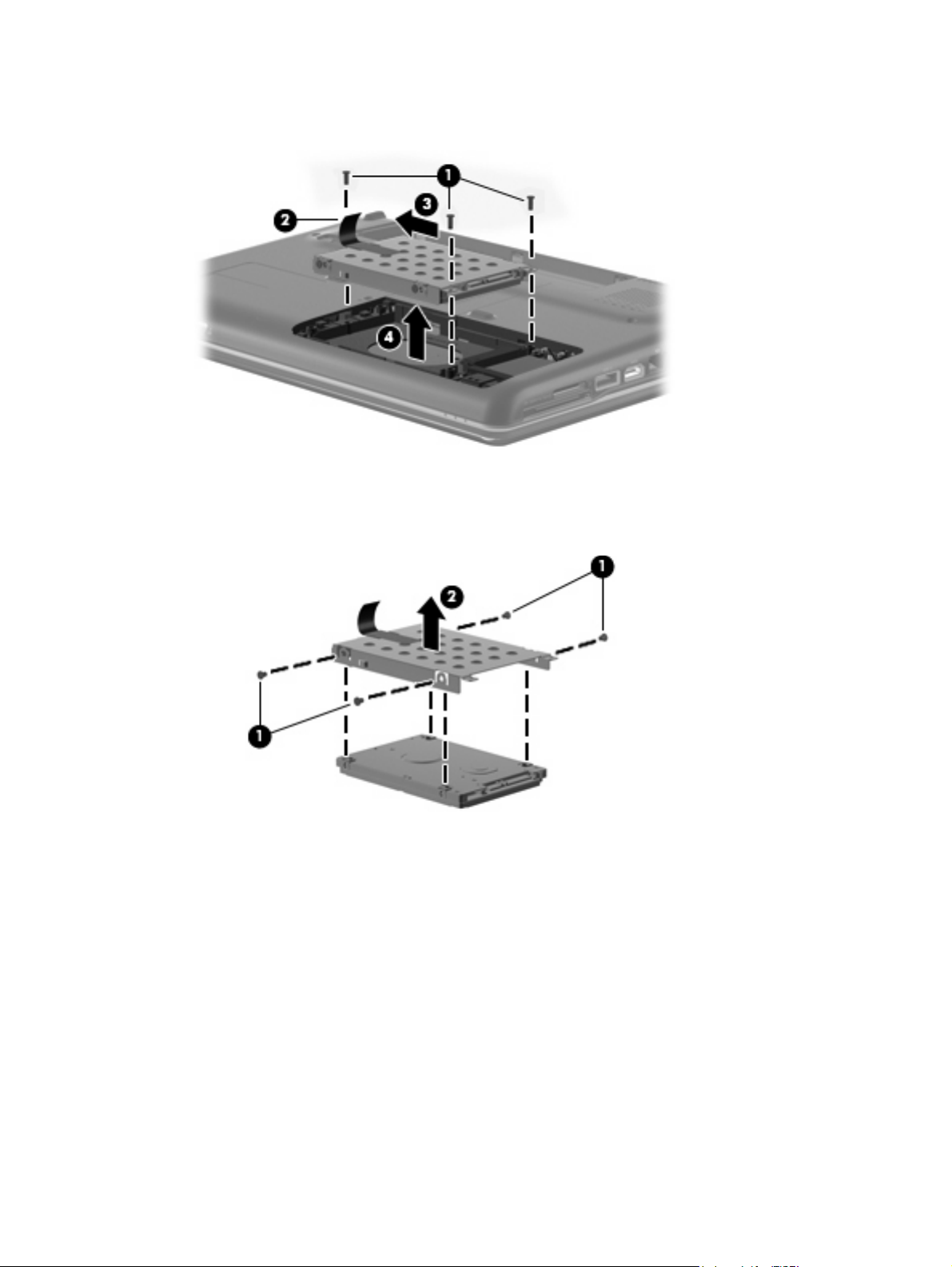
5. Use the Mylar tab (2) to slide the hard drive (3) to the left until it disconnects from the connector,
and then lift the hard drive up and out of the computer (4).
6. If it is necessary to replace the hard drive bracket, remove the four Phillips PM3.0×3.0
screws (1) that secure the hard drive bracket to the hard drive.
7. Lift the bracket (2) straight up to remove it from the hard drive.
Reverse this procedure to reassemble and install the hard drive.
Component replacement procedures 37
Page 46

WLAN module
Description Spare part number
Intel Wi-Fi Link 5100 802.11a/b/g/n WLAN module for use in all countries and regions 480985-001
Intel Wi-Fi Link 5100 802.11a/b/g WLAN module for use in all countries and regions 482957-001
Broadcom 4312 802.11 WLAN b/g module for use in Canada, the Cayman Islands, Guam, Puerto
Rico, Trinidad and Tobago, the U.S. Virgin Islands, and the United States
Broadcom 4322 802.11 a/b/g/n WLAN module for use in Afghanistan, Albania, Algeria, Andorra,
Angola, Antigua and Barbuda, Argentina, Armenia, Australia, Austria, Azerbaijan, Bahamas,
Bahrain, Bangladesh, Barbados, Belarus, Belgium, Belize, Benin, Bhutan, Bolivia, Bosnia and
Herzegovina, Botswana, Brazil, Brunei, Bulgaria, Burkina, Faso Burundi, Cambodia, Cameroon,
Cape Verde, Central African Republic, Chad, Chile, People's Republic of China, Colombia,
Comoros, Congo, Costa Rica, Croatia, Cyprus, Czech Republic, Zaire, Denmark, Djibouti, Dominica,
Dominican Republic, Ecuador, Egypt, El Salvador, Equatorial Guinea, Eritrea, Estonia, Ethiopia, Fiji,
Finland, France, Gabon, Gambia, Georgia, Germany, Ghana, Gibraltar, Greece, Grenada,
Guatemala, Guinea, Guinea-Bissau, Guyana, Haiti, Honduras, Hong Kong, Hungary, Iceland, India,
Indonesia, Ireland, Israel, Italy, Ivory Coast, Jamaica, Japan, Jordan, Kazakhstan, Kenya, Kiribati,
Kuwait, Kyrgyzstan, Laos, Latvia, Lebanon, Lesotho, Liberia, Martinique, British Virgin Islands,
French Guiana, Guadeloupe, Nether Antilles, Aruba, Bermuda, Syria, Liechtenstein, Lithuania,
Luxembourg, Macedonia, Madagascar, Malawi, Malaysia, Maldives, Mali, Malta, Marshall Islands,
Mauritania, Mauritius, Mexico, Micronesia, Monaco, Mongolia, Montenegro, Morocco, Mozambique,
Namibia, Nauru, Nepal, Netherlands, New Zealand, Nicaragua, Niger, Nigeria, Norway, Oman,
Pakistan, Palau, Panama, Papua New Guinea, Paraguay, Peru, Philippines, Poland, Portugal,
Qatar, Republic of Moldova, Romania, Russia, Rwanda, Samoa, San Marino, Sao Tome and
Principe, Saudi Arabia, Senegal, Serbia, Seychelles, Sierra Leone, Singapore, Slovakia, Slovenia,
Solomon Islands, Somalia, South Africa, South Korea, Spain, Sri Lanka, St. Kitts and Nevis, St.
Lucia, St. Vincent and Grenadines, Suriname, Swaziland, Sweden, Switzerland, Taiwan, Tajikistan,
Tanzania, Thailand, East Timor, Togo, Tonga, Trinidad and Tobago, Tunisia, Turkey, Turkmenistan,
Tuvalu, Uganda, Ukraine, United Arab Emirates, The United Kingdom, Uruguay, Uzbekistan,
Vanuatu, Venezuela, Vietnam, Yemen, Zambia, and Zimbabwe
Before removing the WLAN module, follow these steps:
459263-001
487330-002
1. Shut down the computer. If you are unsure whether the computer is off or in Hibernation, turn the
computer on, and then shut it down through the operating system.
2. Disconnect all external devices connected to the computer.
3. Disconnect the power from the computer by first unplugging the power cord from the AC outlet and
then unplugging the AC adapter from the computer.
4. Remove the battery (see
5. Remove the hard drive cover (see
Battery on page 34).
Hard drive on page 36).
Remove the WLAN module:
1. Position the computer with the front toward you.
2. Disconnect the two WLAN antenna cables (1) from the WLAN module.
3. Remove the two Phillips PM2.0×4.0 screws (2) that secure the WLAN module to the computer.
(The edge of the module opposite the slot rises away from the computer.)
38 Chapter 4 Removal and replacement procedures
Page 47

4. Remove the WLAN module (3) by pulling it away from the slot at an angle.
CAUTION: To prevent an unresponsive system, replace the wireless module only with a wireless
module authorized for use in the computer by the governmental agency that regulates wireless
devices in your country or region. If you replace the module and then receive a warning message,
remove the module to restore computer functionality, and then contact technical support through
Help and Support.
NOTE: WLAN modules are designed with a notch (4) to prevent incorrect insertion into the WLAN
module slot.
Reverse this procedure to install a WLAN module.
Component replacement procedures 39
Page 48

RTC battery
Description Spare part number
RTC battery (includes two-sided tape) 486835-001
Before removing the RTC battery, follow these steps:
1. Shut down the computer. If you are unsure whether the computer is off or in Hibernation, turn the
computer on, and then shut it down through the operating system.
2. Disconnect all external devices connected to the computer.
3. Disconnect the power from the computer by first unplugging the power cord from the AC outlet and
then unplugging the AC adapter from the computer.
4. Remove the battery (see
Battery on page 34).
Remove the RTC battery:
1. Loosen the two Phillips PM2.5×5.0 captive screws (1) that secure the RTC battery compartment
cover to the computer.
2. Lift the right side of the RTC battery compartment cover (2), swing it to left, and remove the
cover (3).
3. Disconnect the RTC battery cable (1) from the system board.
40 Chapter 4 Removal and replacement procedures
Page 49

4. Remove the RTC battery (2).
Reverse this procedure to install the RTC battery.
Component replacement procedures 41
Page 50

Memory module
Description Spare part number
1024 MB (PC2-6400, 800-MHz, DDR2) 532331-003
2048 MB (PC2-6400, 800-MHz, DDR2) 532332-003
Before removing the memory module, follow these steps:
1. Shut down the computer. If you are unsure whether the computer is off or in Hibernation, turn the
computer on, and then shut it down through the operating system.
2. Disconnect all external devices connected to the computer.
3. Disconnect the power from the computer by first unplugging the power cord from the AC outlet and
then unplugging the AC adapter from the computer.
4. Remove the battery (see
Battery on page 34).
Remove the memory module:
1. Position the computer with the front toward you.
2. Loosen the Phillips PM2.5×7.0 captive screw (1) that secures the memory module compartment
cover to the computer.
3. Lift the right side of the cover (2), swing it to the left, and lift the cover off the computer (3). The
memory module compartment cover is included in the Plastics Kit, spare part number
486862-001.
4. Spread the retaining tabs (1) on each side of the memory module slot to release the memory
module. (The edge of the module opposite the slot rises away from the computer.)
42 Chapter 4 Removal and replacement procedures
Page 51

5. Remove the module (2) by pulling it away from the slot at an angle.
NOTE: Memory modules are designed with a notch (3) to prevent incorrect insertion into the
memory module slot.
Reverse this procedure to install a memory module.
Component replacement procedures 43
Page 52

Keyboard
For use in: Spare part number
South Korea 486904-AD1
Taiwan 486904-AB1
Thailand 486904-281
The United States 486904-001
Before removing the keyboard, follow these steps:
1. Shut down the computer. If you are unsure whether the computer is off or in Hibernation, turn the
2. Disconnect all external devices connected to the computer.
3. Disconnect the power from the computer by first unplugging the power cord from the AC outlet and
computer on, and then shut it down through the operating system.
then unplugging the AC adapter from the computer.
4. Remove the battery (see
Battery on page 34).
5. Remove the RTC battery compartment cover.
Remove the keyboard:
1. Remove the three Phillips PM2.5×18.0 screws that secure the keyboard to the computer.
2. Turn the computer display-side up, with the front toward you.
3. Open the computer as far as possible.
4. Release the top edge of the keyboard by lifting it up to disengage the keyboard from the tabs on
the keyboard cover.
5. Lift the top edge (1) of the keyboard until it rests at an angle.
44 Chapter 4 Removal and replacement procedures
Page 53

6. Lift the keyboard (2) up until the tabs on the bottom of the keyboard are clear of the keyboard cover.
7. Release the zero insertion force (ZIF) connector (1) to which the keyboard cable is attached and
disconnect the keyboard cable (2) from the system board.
8. Remove the keyboard.
Reverse this procedure to install the keyboard.
Component replacement procedures 45
Page 54

Keyboard cover
Description Spare part number
Keyboard cover (includes power button board and cable) 487299-001
Before removing the keyboard cover, follow these steps:
1. Shut down the computer. If you are unsure whether the computer is off or in Hibernation, turn the
computer on, and then shut it down through the operating system.
2. Disconnect all external devices connected to the computer.
3. Disconnect the power from the computer by first unplugging the power cord from the AC outlet and
then unplugging the AC adapter from the computer.
4. Remove the battery (see
Battery on page 34).
5. Remove the following components:
a. Optical drive (see
b. Hard drive (see
c. Keyboard (see
Optical drive on page 35)
Hard drive on page 36)
Keyboard on page 44)
Remove the keyboard cover:
1. Turn the computer upside down, with the rear toward you.
2. Remove the Phillips PM2.0×2.0 broadhead screw (1) from the optical drive bay, the
Phillips PM2.5×5.0 screw (2) from the hard drive bay, the four Phillips PM2.0×3.0 screws (3) from
the battery bay, and the two Phillips PM2.5×10.0 screws (4) from the base enclosure rear corners
that secure the keyboard cover to the computer.
3. Turn the computer display-side up, with the front toward you.
4. Remove the Phillips PM2.5×6.0 screw (1) from the front left corner of the keyboard cover.
5. Open the computer as far as possible.
46 Chapter 4 Removal and replacement procedures
Page 55

6. Release the ZIF connector to which the power button board cable (2) is connected and disconnect
the cable from the system board.
7. Lift the front edge of the keyboard cover to disengage it from the computer, pull the keyboard cover
toward the display until the light pipe on the front of the keyboard cover clears the top cover, and
then lift the cover up and out of the computer (3).
Reverse this procedure to install the keyboard cover.
Component replacement procedures 47
Page 56

Power button board
Description Spare part number
Power button board 492249-001
Before removing the power button board, follow these steps:
1. Shut down the computer. If you are unsure whether the computer is off or in Hibernation, turn the
computer on, and then shut it down through the operating system.
2. Disconnect all external devices connected to the computer.
3. Disconnect the power from the computer by first unplugging the power cord from the AC outlet and
then unplugging the AC adapter from the computer.
4. Remove the battery (see
Battery on page 34).
5. Remove the following components:
a. Optical drive (see
b. Hard drive (see
c. Keyboard (see
d. Keyboard cover (see
Optical drive on page 35)
Hard drive on page 36)
Keyboard on page 44)
Keyboard cover on page 46)
Remove the power button board:
1. Turn the keyboard cover display-side down.
2. Remove the Phillips PM2.5×3.0 screw (1) from the power button board.
3. Lift the power button board (2) up and away from the keyboard cover.
Reverse this procedure to install the power button board.
48 Chapter 4 Removal and replacement procedures
Page 57

Speaker assembly
Description Spare part number
Speaker assembly 486865-001
Before removing the speaker assembly, follow these steps:
1. Shut down the computer. If you are unsure whether the computer is off or in Hibernation, turn the
computer on, and then shut it down through the operating system.
2. Disconnect all external devices connected to the computer.
3. Disconnect the power from the computer by first unplugging the power cord from the AC outlet and
then unplugging the AC adapter from the computer.
4. Remove the battery (see
Battery on page 34).
5. Remove the following components:
a. Optical drive (see
b. Keyboard (see
c. Keyboard cover (see
Optical drive on page 35)
Keyboard on page 44)
Keyboard cover on page 46)
Remove the speaker assembly:
1. Disconnect the speaker cable (1) from the system board.
2. Release the zero insertion force (ZIF) connector for the num lock cable (2) from the system board.
3. Remove the two Phillips PM2.5×3.0 screws (1) that secure the speaker assembly to the computer.
Component replacement procedures 49
Page 58

4. Lift the speaker assembly (2) straight up to remove it from the computer.
Reverse this procedure to install the speaker assembly.
50 Chapter 4 Removal and replacement procedures
Page 59

Display assembly
Description Spare part number
14.1-in, WXGA BrightView display (includes display panel cable) 487281-001
Before removing the display assembly, follow these steps:
1. Shut down the computer. If you are unsure whether the computer is off or in Hibernation, turn the
computer on, and then shut it down through the operating system.
2. Disconnect all external devices connected to the computer.
3. Disconnect the power from the computer by first unplugging the power cord from the AC outlet and
then unplugging the AC adapter from the computer.
4. Remove the battery (see
5. Disconnect the wireless antenna cables from the WLAN module (see
Battery on page 34).
WLAN module on page 38).
6. Remove the following components:
a. Optical drive (see
b. Keyboard (see
c. Keyboard cover (see
d. Speaker assembly (see
Optical drive on page 35)
Keyboard on page 44)
Keyboard cover on page 46)
Speaker assembly on page 49)
Remove the display assembly:
1. Turn the computer display-side up, with the front toward you.
2. Open the display as far as possible.
3. Remove the wireless antenna cable (1) from the hole in the system board and the routing channels
and clips built into the top cover.
4. Disconnect the display panel cable (2) that runs along the left side.
Component replacement procedures 51
Page 60

5. Remove the microphone cable (1) from the hole in the system board and the routing channels and
clips built into the top cover.
6. Disconnect the microphone cable from the system board (2).
CAUTION: Support the display assembly when removing the following screws. Failure to support
the display assembly can result in damage to the display assembly and other computer
components.
7. Remove the four black Phillips PM2.5×6.0 screws (1) that secure the display assembly to the
computer.
8. Remove the display assembly (2).
52 Chapter 4 Removal and replacement procedures
Page 61

9. If it is necessary to replace any of the display assembly internal components, remove the following
screw covers and screws. The display rubber screw covers are included in the Display Rubber Kit,
spare part number 487283-001.
(1) Two Mylar screw covers on the display bezel bottom edge
(2) Two Phillips PM2.5×5.0 screws
10. Flex the top side (1), the left and right sides (2), and the bottom (3) of the display bezel until the
bezel disengages from the display enclosure.
11. Remove the display bezel (4). The display bezel is available using spare part number
487286-001.
12. If it is necessary to replace the inverter, release the inverter (1) from the clips in the display
enclosure as far as the display panel cable and the backlight cable will allow.
Component replacement procedures 53
Page 62

13. Disconnect the backlight cable (2) and the display panel cable (3) from the display inverter. The
display inverter is available using spare part number 486736-001.
14. Remove the inverter.
15. If it is necessary to replace the display panel, remove the six black Phillips PM2.5×5.0 screws (1)
that secure the display panel to the display enclosure, and then lift the panel from the
enclosure (2). The display panel is available using the spare part number 487279-001.
16. If it is necessary to replace the display cable, follow these steps:
a. Peel back the plastic (1) that covers the cable.
b. Remove the tape (2) that secures the cable to the display.
c. Unplug the cable (3) from the display.
d. Remove the cable from the display (4).
54 Chapter 4 Removal and replacement procedures
Page 63

The display cable is available using spare part number 486735-001.
17. If it is necessary to replace the display hinges, remove the four silver Phillips PM2.0×3.0
screws (1) that secure each hinge to the display.
18. Remove the display hinges (2) from the display. The display hinges are available using spare part
number 486737-001.
19. If it is necessary to replace the wireless antenna transceivers and cables, remove the
Phillips PM2.5×3.0 screw (1) that secures each transceiver to the display enclosure.
20. Detach the wireless antenna transceivers (2) from the display enclosure. The transceivers are
secured by a foil wrapping.
21. Remove the wireless antenna cables from the clips (3) built into the display enclosure.
Component replacement procedures 55
Page 64

22. Remove the wireless antenna transceivers and cables (4) from the display enclosure.
Reverse this procedure to reassemble and install the display assembly.
56 Chapter 4 Removal and replacement procedures
Page 65

Camera module
Description Spare part number
Camera module 487287-001
Before removing the camera module, follow these steps:
1. Shut down the computer. If you are unsure whether the computer is off or in Hibernation, turn the
computer on, and then shut it down through the operating system.
2. Disconnect all external devices connected to the computer.
3. Disconnect the power from the computer by first unplugging the power cord from the AC outlet and
then unplugging the AC adapter from the computer.
4. Remove the battery (see
Battery on page 34).
5. Remove the following components:
a. Optical drive (see
b. Keyboard (see
c. Keyboard cover (see
d. Speaker assembly (see
e. Display assembly (see
Optical drive on page 35)
Keyboard on page 44)
Keyboard cover on page 46)
Speaker assembly on page 49)
Display assembly on page 51)
Remove the camera module:
1. Disconnect the cable (2) and remove the camera module from the display enclosure.
2. Release the camera module (1) from the display enclosure.
Reverse this procedure to install the camera module.
Component replacement procedures 57
Page 66

Microphone module
Description Spare part number
Microphone module and cable 517629-001
Before removing the microphone module, follow these steps:
1. Shut down the computer. If you are unsure whether the computer is off or in Hibernation, turn the
computer on, and then shut it down through the operating system.
2. Disconnect all external devices connected to the computer.
3. Disconnect the power from the computer by first unplugging the power cord from the AC outlet and
then unplugging the AC adapter from the computer.
4. Remove the battery (see
Battery on page 34).
5. Remove the following components:
a. Optical drive (see
b. Keyboard (see
c. Keyboard cover (see
d. Speaker assembly (see
e. Display assembly (see
Optical drive on page 35)
Keyboard on page 44)
Keyboard cover on page 46)
Speaker assembly on page 49)
Display assembly on page 51)
Remove the microphone module:
1. Release the tabs (1) built into the display enclosure.
2. Release the microphone receiver (2) from the display enclosure. The microphone receiver is
secured by two-sided tape.
3. Remove the microphone cable (3) and receiver from the display enclosure.
Reverse this procedure to install the microphone module.
58 Chapter 4 Removal and replacement procedures
Page 67

Top cover
Description Spare part number
Top cover (includes TouchPad and cable) 487300-001
Before removing the top cover, follow these steps:
1. Shut down the computer. If you are unsure whether the computer is off or in Hibernation, turn the
2. Disconnect all external devices connected to the computer.
3. Disconnect the power from the computer by first unplugging the power cord from the AC outlet and
computer on, and then shut it down through the operating system.
then unplugging the AC adapter from the computer.
4. Remove the battery (see
Battery on page 34).
5. Remove the following components:
a. Hard drive (see
b. Optical drive (see
c. Keyboard (see
d. Keyboard cover (see
e. Speaker assembly (see
f. Display assembly (see
Hard drive on page 36)
Optical drive on page 35)
Keyboard on page 44)
Keyboard cover on page 46)
Speaker assembly on page 49)
Display assembly on page 51)
Remove the top cover:
1. Turn the computer upside down, with the front toward you.
2. Remove the seven screws that secure the top cover to the computer.
(1) Three Phillips PM2.5×10.0 screws
●
(2) Two Phillips PM2.5×5.0 screws
●
(3) Two Phillips PM2.0×3.0 screws
●
Component replacement procedures 59
Page 68

3. Turn the computer right-side up, with the front toward you.
4. Disconnect the following cables from the system board:
Bluetooth module cable (1)
●
TouchPad cable (2) with zero insertion force (ZIF) connector
●
5. Remove the two Phillips PM2.5×6.0 screws (1) that secure the top cover to the computer.
6. Lift up the rear edge of the top cover until it releases from the base (2).
60 Chapter 4 Removal and replacement procedures
Page 69

7. Remove the top cover (3).
Reverse this procedure to install the top cover.
Component replacement procedures 61
Page 70

TouchPad button board
Description Spare part number
TouchPad bracket 494962-001
TouchPad button board 494965-001
Before removing the TouchPad button board, follow these steps:
1. Shut down the computer. If you are unsure whether the computer is off or in Hibernation, turn the
computer on, and then shut it down through the operating system.
2. Disconnect all external devices connected to the computer.
3. Disconnect the power from the computer by first unplugging the power cord from the AC outlet and
then unplugging the AC adapter from the computer.
4. Remove the battery (see
Battery on page 34).
5. Remove the following components:
a. Hard drive (see
b. Optical drive (see
c. Keyboard (see
d. Keyboard cover (see
e. Speaker assembly (see
f. Display assembly (see
g. Top cover (see
Hard drive on page 36)
Optical drive on page 35)
Keyboard on page 44)
Keyboard cover on page 46)
Speaker assembly on page 49)
Display assembly on page 51)
Top cover on page 59)
Remove the TouchPad button board:
1. Turn the top cover upside down with the front toward you.
2. Release the zero insertion force (ZIF) connector for the TouchPad button board cable (1).
3. Remove the three black Phillips PM2.5×3.0 screws (2) and one silver Phillips PM2.5×4.0
screw (3) that secure the TouchPad assembly to the top cover.
4. Remove the TouchPad bracket (4) from the top cover.
62 Chapter 4 Removal and replacement procedures
Page 71

5. Remove the TouchPad button board (5) from the TouchPad bracket.
Reverse this procedure to reassemble and install the TouchPad button board.
Component replacement procedures 63
Page 72

Bluetooth module
Description Spare part number
Bluetooth module 483113-001
Before removing the Bluetooth module, follow these steps:
1. Shut down the computer. If you are unsure whether the computer is off or in Hibernation, turn the
computer on, and then shut it down through the operating system.
2. Disconnect all external devices connected to the computer.
3. Disconnect the power from the computer by first unplugging the power cord from the AC outlet and
then unplugging the AC adapter from the computer.
4. Remove the battery (see
Battery on page 34).
5. Remove the following components:
a. Hard drive (see
b. Optical drive (see
c. Keyboard (see
d. Keyboard cover (see
e. Speaker assembly (see
f. Display assembly (see
g. Top cover (see
Hard drive on page 36)
Optical drive on page 35)
Keyboard on page 44)
Keyboard cover on page 46)
Speaker assembly on page 49)
Display assembly on page 51)
Top cover on page 59)
Remove the Bluetooth module:
1. Turn the top cover upside down with the front toward you.
2. Disconnect the Bluetooth module cable (1) from the system board.
3. Remove the two silver PM2.0×3.0 screws (2) and the tab (3) that secure the Bluetooth module to
the top cover.
4. Release the cable from the routing channels built into the system board (4).
64 Chapter 4 Removal and replacement procedures
Page 73

5. Remove the Bluetooth module (5) from the top cover.
Reverse this procedure to install the Bluetooth module.
Component replacement procedures 65
Page 74

Modem module (select models only)
Description Spare part number
Modem module for use in all countries and regions except Australia and New Zealand 461749-001
Modem module for use only in Australia and New Zealand 461749-011
Modem module cable (includes RJ-11 connector) 494981-001
Before removing the modem module, follow these steps:
1. Shut down the computer. If you are unsure whether the computer is off or in Hibernation, turn the
computer on, and then shut it down through the operating system.
2. Disconnect all external devices connected to the computer.
3. Disconnect the power from the computer by first unplugging the power cord from the AC outlet and
then unplugging the AC adapter from the computer.
4. Remove the battery (see
Battery on page 34).
5. Remove the following components:
a. Hard drive (see
b. Optical drive (see
c. Keyboard (see
d. Keyboard cover (see
e. Speaker assembly (see
f. Display assembly (see
g. Top cover (see
Hard drive on page 36)
Optical drive on page 35)
Keyboard on page 44)
Keyboard cover on page 46)
Speaker assembly on page 49)
Display assembly on page 51)
Top cover on page 59)
Remove the modem module:
1. Turn the computer display-side up, with the front toward you.
2. Remove the two Phillips PM2.0×4.0 screws (1) that secure the modem module to the system board.
3. Disconnect the modem module cable (2) from the modem module.
66 Chapter 4 Removal and replacement procedures
Page 75
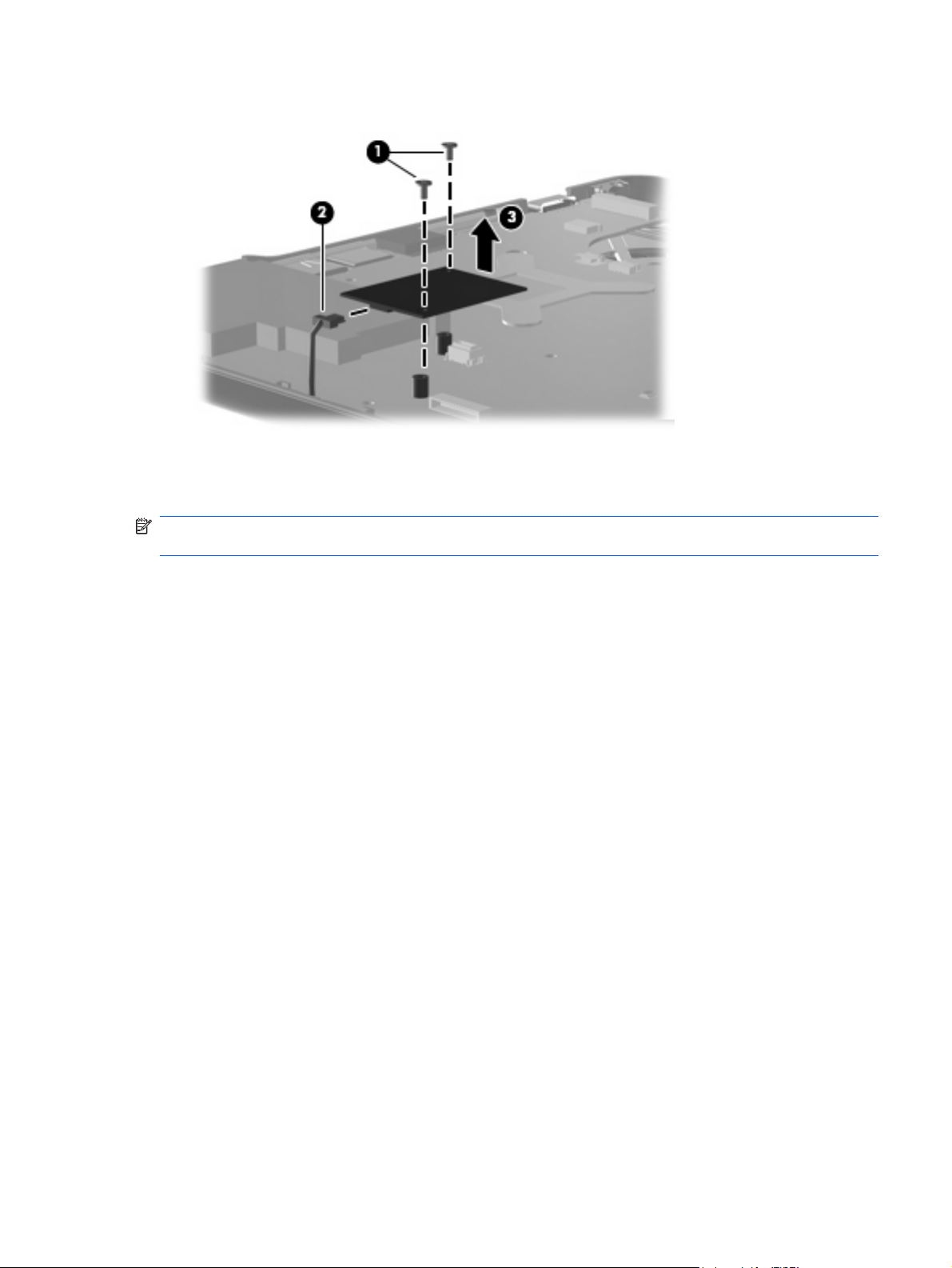
4. Lift up on the front of the modem module (3) to disconnect it from the system board.
5. Remove the modem module.
Reverse this procedure to install the modem module.
NOTE: When replacing the modem module, be sure that the connector on the bottom of the modem
module connects firmly into the system board.
Component replacement procedures 67
Page 76

Audio board
Description Spare part number
Audio board (includes audio connectors and audio board cable) 487344-001
Before removing the audio board, follow these steps:
1. Shut down the computer. If you are unsure whether the computer is off or in Hibernation, turn the
computer on, and then shut it down through the operating system.
2. Disconnect all external devices connected to the computer.
3. Disconnect the power from the computer by first unplugging the power cord from the AC outlet and
then unplugging the AC adapter from the computer.
4. Remove the battery (see
Battery on page 34).
5. Remove the following components:
a. Hard drive (see
b. Optical drive (see
c. Keyboard (see
d. Keyboard cover (see
e. Speaker assembly (see
f. Display assembly (see
g. Top cover (see
Hard drive on page 36)
Optical drive on page 35)
Keyboard on page 44)
Keyboard cover on page 46)
Speaker assembly on page 49)
Display assembly on page 51)
Top cover on page 59)
Remove the audio board:
1. Turn the computer display-side up, with the front toward you.
2. Disconnect the audio board cable (1) from the system board.
3. Remove the cable from between the components that secure it in the base (2).
4. Remove the two Phillips PM2.5×3.0 screws (3) that secure the audio board to the computer.
5. Lift the rear edge of the audio board and raise it until the audio connectors disengage from the
base enclosure.
68 Chapter 4 Removal and replacement procedures
Page 77

6. Remove the audio board (4).
Reverse this procedure to install the audio board.
Component replacement procedures 69
Page 78

USB board
Description Spare part number
USB board 486842-001
USB board cable 486843-001
Before removing the USB board, follow these steps:
1. Shut down the computer. If you are unsure whether the computer is off or in Hibernation, turn the
2. Disconnect all external devices connected to the computer.
3. Disconnect the power from the computer by first unplugging the power cord from the AC outlet and
computer on, and then shut it down through the operating system.
then unplugging the AC adapter from the computer.
4. Remove the battery (see
Battery on page 34).
5. Remove the following components:
a. Hard drive (see
b. Optical drive (see
c. Keyboard (see
d. Keyboard cover (see
e. Speaker assembly (see
f. Display assembly (see
g. Top cover (see
Hard drive on page 36)
Optical drive on page 35)
Keyboard on page 44)
Keyboard cover on page 46)
Speaker assembly on page 49)
Display assembly on page 51)
Top cover on page 59)
Remove the USB board:
1. Turn the computer display-side up, with the right side toward you.
2. Disconnect the USB board cable (1) from the system board.
3. Remove the cable from the base enclosure clips (2).
4. Remove the Phillips PM2.5×3.0 screw (3) that secures the USB board to the computer.
70 Chapter 4 Removal and replacement procedures
Page 79

5. Lift the USB board (4) straight up to remove it from the computer.
Reverse this procedure to install the USB board.
Component replacement procedures 71
Page 80

Power connector cable
Description Spare part number
Power connector cable (includes power connector) 486864-001
Before removing the power connector cable, follow these steps:
1. Shut down the computer. If you are unsure whether the computer is off or in Hibernation, turn the
computer on, and then shut it down through the operating system.
2. Disconnect all external devices connected to the computer.
3. Disconnect the power from the computer by first unplugging the power cord from the AC outlet and
then unplugging the AC adapter from the computer.
4. Remove the battery (see
Battery on page 34).
5. Remove the following components:
a. Hard drive (see
b. Optical drive (see
c. Keyboard (see
d. Keyboard cover (see
e. Speaker assembly (see
f. Display assembly (see
g. Top cover (see
Hard drive on page 36)
Optical drive on page 35)
Keyboard on page 44)
Keyboard cover on page 46)
Speaker assembly on page 49)
Display assembly on page 51)
Top cover on page 59)
Remove the power connector cable:
1. Turn the computer display-side up, with the right side toward you.
2. Disconnect the power connector cable (1) from the bottom of the system board.
3. Remove the power connector (2) from the clip built into the base enclosure. The power connector
is secured by two-sided tape.
72 Chapter 4 Removal and replacement procedures
Page 81

4. Remove the cable from the base enclosure clips (3).
Reverse this procedure to install the power connector cable.
Component replacement procedures 73
Page 82

System board
Description Spare part number
System board (includes thermal material) 532327-001
When replacing the system board, be sure that the following components are removed from the defective
system board and installed on the replacement system board:
RTC battery (see
●
Memory module (see
●
WLAN module (see
●
Modem module (select models only, see
●
RTC battery on page 40)
Memory module on page 42)
WLAN module on page 38)
Modem module (select models only) on page 66)
Before removing the system board, follow these steps:
1. Shut down the computer. If you are unsure whether the computer is off or in Hibernation, turn the
computer on, and then shut it down through the operating system.
2. Disconnect all external devices connected to the computer.
3. Disconnect the power from the computer by first unplugging the power cord from the AC outlet and
then unplugging the AC adapter from the computer.
4. Remove the battery (see
Battery on page 34).
5. Remove the following components:
a. Hard drive (see
b. Optical drive (see
c. Keyboard (see
Hard drive on page 36)
Optical drive on page 35)
Keyboard on page 44)
d. Keyboard cover (see
e. Speaker assembly (see
f. Display assembly (see
g. Top cover (see
Keyboard cover on page 46)
Speaker assembly on page 49)
Display assembly on page 51)
Top cover on page 59)
Remove the system board:
1. Turn the computer display-side up, with the right side toward you.
2. Disconnect the following cables from the system board:
(1) Modem cable (see
●
(2) Audio board cable (see
●
(3) Fan cable (see
●
Modem module (select models only) on page 66)
Audio board on page 68)
Fan on page 81)
74 Chapter 4 Removal and replacement procedures
Page 83

(4) USB board cable (see
●
USB board on page 70)
3. Disconnect the power connector cable.
4. Remove the two black Phillips PM2.5×5.0 screws that secure the system board to the computer.
5. Lift the right side of the system board (1) until it rests at an angle (2).
Component replacement procedures 75
Page 84

6. Release the system board by sliding it to the right at an angle (3) until the connectors on the left
side of the system board disengage from the base enclosure, and then remove the system board.
7. If it is necessary to replace the modem module cable, remove the RJ-11 connector (1) from the
clip built into the base enclosure.
8. Remove the modem module cable (2) from the routing channel built into the base enclosure. The
modem module cable is available using spare part number 494981-001.
When replacing the system board, be sure that the following components are removed from the defective
system board and installed on the replacement system board:
Heat sink (see
●
Processor (see
●
Heat sink on page 77)
Processor on page 79)
Reverse this procedure to install the system board.
76 Chapter 4 Removal and replacement procedures
Page 85

Heat sink
Description Spare part number
Heat sink (includes thermal material) 530614-001
NOTE: To properly ventilate the computer, allow at least a 7.6-cm (3-in) clearance on the right side
and rear panel of the computer. The computer uses an electric fan for ventilation. The fan is controlled
by a temperature sensor and is designed to turn on automatically when high temperature conditions
exist. These conditions are affected by high external temperatures, system power consumption, power
management/battery conservation configurations, battery fast charging, and software requirements.
Exhaust air is displaced through the ventilation grill located on the left side of the computer.
NOTE: Thermal pads and thermal paste are included with all heat sink, system board, and processor
spare part kits.
Before removing the heat sink, follow these steps:
1. Shut down the computer. If you are unsure whether the computer is off or in Hibernation, turn the
2. Disconnect all external devices connected to the computer.
3. Disconnect the power from the computer by first unplugging the power cord from the AC outlet and
computer on, and then shut it down through the operating system.
then unplugging the AC adapter from the computer.
4. Remove the battery (see
Battery on page 34).
5. Remove the following components:
a. Hard drive (see
b. Optical drive (see
c. Keyboard (see
d. Keyboard cover (see
e. Speaker assembly (see
f. Display assembly (see
g. Top cover (see
h. System board (see
Hard drive on page 36)
Optical drive on page 35)
Keyboard on page 44)
Keyboard cover on page 46)
Speaker assembly on page 49)
Display assembly on page 51)
Top cover on page 59)
System board on page 74)
Remove the heat sink:
1. Turn the system board upside down with the external monitor port toward you.
2. Loosen the four Phillips PM2.0×10.0 captive screws (1) that secure the heat sink to the system
board.
NOTE: Due to the adhesive quality of the thermal material located between the heat sink and
system board components, it may be necessary to move the heat sink from side to side to detach
the assembly.
Component replacement procedures 77
Page 86

3. Remove the heat sink (2).
NOTE: The thermal material must be thoroughly cleaned from the surface of the heat sink (1) and the
processor (2) each time the heat sink is removed. Thermal pads and thermal paste must also be installed
on all surfaces before the heat sink is reinstalled. Thermal pads must be placed in all of the following
locations on the heat sink: the four specifically marked areas (3), the nVIDIA video chip (4), the
Northbridge chip (5), and the capacitors (6).
Reverse this procedure to install the heat sink.
78 Chapter 4 Removal and replacement procedures
Page 87

Processor
NOTE: The processor spare part kit includes thermal material.
Description Spare part number
Intel T9550 Core2 Duo mobile processor (2.66 GHz, 6-MB L2 cache) 507953-001
Intel P8700 Core2 Duo mobile processor (2.53 GHz, 3-MB L2 cache) 507960-001
Intel P8600 Core2 Duo mobile processor (2.40 GHz, 3-MB L2 cache) 507963-001
Intel P8400 Core2 Duo mobile processor (2.26 GHz, 3-MB L2 cache) 507964-001
Intel P7450 Core2 Duo mobile processor (2.13 GHz, 3-MB L2 cache) 507965-001
Intel T5800 Core2 Duo mobile processor (2.06 GHz, 2-MB L2 cache) 515040-001
Intel T6400 Core2 Duo mobile processor (2.00 GHz, 2-MB L2 cache) 513592-001
Intel T6600 Core2 Duo mobile processor (2.20 GHz, 2-MB L2 cache) 513593-001
Intel T3400 Pentium processor for mobile (2.16 GHz, 1-MB cache) 509549-001
Intel T4200 Pentium processor for mobile (2.00 GHz, 1-MB cache) 513599-001
Before removing the processor, follow these steps:
1. Shut down the computer. If you are unsure whether the computer is off or in Hibernation, turn the
computer on, and then shut it down through the operating system.
2. Disconnect all external devices connected to the computer.
3. Disconnect the power from the computer by first unplugging the power cord from the AC outlet and
then unplugging the AC adapter from the computer.
4. Remove the battery (see
Battery on page 34).
5. Remove the following components:
a. Hard drive (see
b. Optical drive (see
c. Keyboard (see
d. Keyboard cover (see
e. Speaker assembly (see
f. Display assembly (see
g. Top cover (see
h. System board (see
Hard drive on page 36)
Optical drive on page 35)
Keyboard on page 44)
Keyboard cover on page 46)
Speaker assembly on page 49)
Display assembly on page 51)
Top cover on page 59)
System board on page 74)
i. Heat sink (see
Heat sink on page 77)
Remove the processor:
1. Turn the processor locking screw (1) one-half turn counterclockwise until you hear a click.
Component replacement procedures 79
Page 88

2. Lift the processor (2) straight up and remove it.
NOTE: The gold triangle (3) on the processor must be aligned with the triangle icon (4) embossed
on the processor socket when you install the processor.
Reverse this procedure to install the processor.
80 Chapter 4 Removal and replacement procedures
Page 89

Fan
Description Spare part number
Fan 486844-001
Before removing the fan, follow these steps:
1. Shut down the computer. If you are unsure whether the computer is off or in Hibernation, turn the
computer on, and then shut it down through the operating system.
2. Disconnect all external devices connected to the computer.
3. Disconnect the power from the computer by first unplugging the power cord from the AC outlet and
then unplugging the AC adapter from the computer.
4. Remove the battery (see
Battery on page 34).
5. Remove the following components:
a. Hard drive (see
b. Optical drive (see
c. Keyboard (see
d. Keyboard cover (see
e. Speaker assembly (see
f. Display assembly (see
g. Top cover (see
h. System board (see
Hard drive on page 36)
Optical drive on page 35)
Keyboard on page 44)
Keyboard cover on page 46)
Speaker assembly on page 49)
Display assembly on page 51)
Top cover on page 59)
System board on page 74)
Remove the fan:
1. Position the base enclosure with the front toward you.
2. Remove the two black Phillips PM2.5×5.0 screws (1) that secure the fan to the computer.
Component replacement procedures 81
Page 90

3. Lift the fan from the base enclosure (2).
Reverse this procedure to install the fan.
82 Chapter 4 Removal and replacement procedures
Page 91

5 Setup Utility
WARNING! Only authorized technicians trained by HP must repair this equipment. All troubleshooting
and repair procedures are detailed to allow repair at only the subassembly or module level. Because of
the complexity of the individual boards and subassemblies, do not attempt to make repairs at the
component level or modify any printed wiring board. Improper repairs can create a safety hazard. Any
indication of component replacement or printed wiring board modification may void any warranty or
exchange allowances.
Starting the Setup Utility
The Setup Utility is a ROM-based information and customization utility that can be used even when your
Windows® operating system is not working.
The utility reports information about the computer and provides settings for startup, security, and other
preferences.
To start the Setup Utility:
Open the Setup Utility by turning on or restarting the computer. While the “Press the ESC key for
Startup Menu” message is displayed in the lower-left corner of the screen, press f10.
– or –
1. Open the Setup Utility by turning on or restarting the computer. While the “Press the ESC key for
Startup Menu” message is displayed in the lower-left corner of the screen, press esc.
2. When the Startup Menu is displayed, press f10.
Starting the Setup Utility 83
Page 92

Changing the language of the Setup Utility
The following procedure explains how to change the language of the Setup Utility. If the Setup Utility is
not already running, begin at step 1. If the Setup Utility is already running, begin at step 2.
1. Open the Setup Utility by turning on or restarting the computer. While the “Press the ESC key for
Startup Menu” message is displayed in the lower-left corner of the screen, press f10.
– or –
Open the Setup Utility by turning on or restarting the computer. While the “Press the ESC key for
Startup Menu” message is displayed in the lower-left corner of the screen, press esc. When the
Startup Menu is displayed, press f10.
2. Use the arrow keys to select System Configuration > Language, and then press enter.
3. Use the arrow keys to select a language, and then press enter.
4. When a confirmation prompt with your language selected is displayed, press enter.
5. To save your change and exit the Setup Utility, use the arrow keys to select Exit > Exit Saving
Changes, and then press enter.
Your change goes into effect immediately.
Navigating and selecting in the Setup Utility
Because the Setup Utility is not Windows based, it does not support the TouchPad. Navigation and
selection are by keystroke.
To choose a menu or a menu item, use the arrow keys.
●
To choose an item in a list or to toggle a field, for example an Enable/Disable field, use either the
●
arrow keys or f5 or f6.
To select an item, press enter.
●
To close a text box or return to the menu display, press esc.
●
To display additional navigation and selection information while the Setup Utility is open,
●
press f1.
84 Chapter 5 Setup Utility
Page 93

Displaying system information
The following procedure explains how to display system information in the Setup Utility. If the Setup
Utility is not open, begin at step 1. If the Setup Utility is open, begin at step 2.
1. Open the Setup Utility by turning on or restarting the computer. While the “Press the ESC key for
Startup Menu” message is displayed in the lower-left corner of the screen, press f10.
– or –
Open the Setup Utility by turning on or restarting the computer. While the “Press the ESC key for
Startup Menu” message is displayed in the lower-left corner of the screen, press esc. When the
Startup Menu is displayed, press f10.
2. Select the Main menu. System information such as the system time and date, and identification
information about the computer is displayed.
3. To exit the Setup Utility without changing any settings, use the arrow keys to select Exit > Exit
Discarding Changes, and then press enter.
Restoring default settings in the Setup Utility
The following procedure explains how to restore the Setup Utility default settings. If the Setup Utility is
not already running, begin at step 1. If the Setup Utility is already running, begin at step 2.
1. Open the Setup Utility by turning on or restarting the computer. While the “Press the ESC key for
Startup Menu” message is displayed in the lower-left corner of the screen, press f10.
– or –
Open the Setup Utility by turning on or restarting the computer. While the “Press the ESC key for
Startup Menu” message is displayed in the lower-left corner of the screen, press esc. When the
Startup Menu is displayed, press f10.
2. Use the arrow keys to select Exit > Load Setup Defaults, and then press enter.
3. When the Setup Confirmation is displayed, press enter.
4. To save your change and exit the Setup Utility, use the arrow keys to select Exit > Exit Saving
Changes, and then press enter.
The Setup Utility default settings go into effect when the computer restarts.
NOTE: Your password, security, and language settings are not changed when you restore the factory
default settings.
Displaying system information 85
Page 94

Exiting the Setup Utility
You can exit the Setup Utility with or without saving changes.
To exit the Setup Utility and save your changes from the current session:
●
If the Setup Utility menus are not visible, press esc to return to the menu display. Then use the
arrow keys to select Exit > Exit Saving Changes, and then press enter.
To exit the Setup Utility without saving your changes from the current session:
●
If the Setup Utility menus are not visible, press esc to return to the menu display. Then use the
arrow keys to select Exit > Exit Discarding Changes, and then press enter.
After either choice, the computer restarts in Windows.
86 Chapter 5 Setup Utility
Page 95

Setup Utility menus
The menu tables in this section provide an overview of Setup Utility options.
NOTE: Some of the Setup Utility menu items listed in this section may not be supported by your
computer.
Main menu
Select To do this
System information
View and change the system time and date.
●
View identification information about the computer.
●
View specification information about the processor, memory size,
●
system BIOS, and keyboard controller version (select models only).
Security menu
Select To do this
Administrator password Enter, change, or delete an administrator password.
Power-On Password Enter, change, or delete a power-on password.
System Configuration menu
Select To do this
Language Support Change the Setup Utility language.
Button Sound (select models only) Enable/disable the capacitive button tapping sound.
Virtualization Technology Enable/disable the processor Virtualization Technology.
Processor C6 State (select models only) Enable/disable the processor C6 sleep state.
LAN Power Saving (select models only) Enable/disable LAN Power Saving. When enabled, saves power when
the computer is in DC mode.
Card Reader/1394 Power Saving (select models
only)
Fan Always On Enable/disable Fan Always On. When enabled, the computer fan will
Boot Options Set the following boot options:
Enable/disable Card Reader/1394 Power Saving. When enabled, saves
power when the computer is in DC mode.
always be on.
f9 and f10 Delay (sec.)―Set the delay for the f9 and f10 functions
●
of the Setup Utility in intervals of 5 seconds each (0, 5, 10, 15, 20).
CD-ROM boot―Enable/disable boot from CD-ROM.
●
Floppy boot―Enable/disable boot from diskette.
●
Internal Network Adapter boot―Enable/disable boot from Internal
●
Network Adapter.
Boot Order―Set the boot order for:
●
Setup Utility menus 87
Page 96

Select To do this
USB Floppy
◦
Internal CD/DVD ROM drive
◦
USB CD/DVD ROM drive
◦
Hard drive
◦
USB Diskette on Key
◦
USB Hard drive
◦
Network adapter
◦
Diagnostics menu
Select To do this
Hard Disk Self Test Run a comprehensive self-test on the hard drive.
NOTE: On models with two hard drives, this menu option is called the
Primary Hard Disk Self Test.
Secondary Hard Disk Self Test (select models
only)
Memory Test Run a diagnostic test on the system memory.
Run a comprehensive self-test on a secondary hard drive.
88 Chapter 5 Setup Utility
Page 97

6 Specifications
Computer specifications
Metric U.S.
Dimensions
Height (front to back)
Width 33.40 cm 13.15 in
Depth 23.70 cm 9.33 in
Weight (with optical drive, hard drive, panel, battery,
and 1 DIMM)
Input power
Operating voltage
Operating current 3.5 A or 4.74 A
Temperature
Operating (not writing to optical disc)
Operating (writing to optical disc) 5°C to 35°C 41°F to 95°F
Non-operating -20°C to 60°C -4°F to 140°F
Relative humidity
Operating
Non-operating 5% to 95%
Maximum altitude (unpressurized)
Operating
3.33 to 3.97 cm 1.31 to 1.56 in
2.30 kg 5.07 lb
18.5 V dc to 19.0 V dc
0°C to 35°C 32°F to 95°F
10% to 90%
-15 m to 3,048 m -50 ft to 10,000 ft
Non-operating -15 m to 12,192 m -50 ft to 40,000 ft
NOTE: Applicable product safety standards specify thermal limits for plastic surfaces. The computer operates well within this
range of temperatures.
Computer specifications 89
Page 98

14.1-in, WXGA BrightView display specifications
Metric U.S.
Dimensions
Height
Width 18.98 cm 7.47 in
Diagonal 35.82 cm 14.10 in
Number of colors More than 262,144
Contrast ratio More than 300:1
Brightness 200 nits (typical)
Pixel resolution
Pitch
Format 1280 × 800
Configuration RGB vertical stripe
Backlight Edge lit
Character display 80 × 25
Total power consumption 5.2 W
Viewing angle +/-40° horizontal, +15/-35° vertical (typical)
30.37 cm 11.96 in
0.2373 × 0.2373 mm
90 Chapter 6 Specifications
Page 99

Hard drive specifications
500 GB* 320 GB* 250 GB* 160 GB*
Dimensions
Height
Width 70 mm 70 mm 70 mm 70 mm
Weight 101 g 101 g 102 g 102 g
Interface type SATA SATA SATA SATA
Transfer rate
Synchronous (maximum)
Security ATA security ATA security ATA security ATA security
Seek times (typical read, including setting)
Single track
Average 12 ms 12 ms 13 ms 13 ms
Maximum 22 ms 22 ms 24 ms 24 ms
Logical blocks 976,773,168 625,142,448 488,397,168 312,581,808
Disk rotational speed 5400 rpm
Operating temperature 5°C to 55°C (41°F to 131°F)
NOTE: Certain restrictions and exclusions apply. Consult technical support for details.
*1 GB = 1 billion bytes when referring to hard drive storage capacity. Accessible capacity is less. Actual drive specifications
may differ slightly.
9.5 mm 9.5 mm 9.5 mm 9.5 mm
300 MB/sec 300 MB/sec 100 MB/sec 100 MB/sec
1.5 ms 1.5 ms 3 ms 3 ms
Hard drive specifications 91
Page 100

DVD±RW and CD-RW SuperMulti Double-Layer Combo
Drive specifications
Applicable disc Read:
CD-DA, CD+(E)G, CD-MIDI, CD-TEXT,
CD-ROM, CD-ROM XA, MIXED MODE
CD, CD-I, CD-I Bridge (Photo-CD, Video
CD), MultiSession CD (Photo-CD,
CD-EXTRA, Portfolio, CD-R, CD-RW),
CD-R, CD-RW, DVD-ROM (DVD-5,
DVD-9, DVD-10, DVD-18), DVD-R,
DVD-RW, DVD+R, DVD+RW, DVD-RAM
Access time CD DVD
Random < 175 ms < 230 ms
Cache buffer 2 MB
Data transfer rate
24X CD-ROM
8X DVD 10,800 KB/sec
24X CD-R 3,600 KB/sec
16X CD-RW 2,400 KB/sec
8X DVD+R 10,800 KB/sec
4X DVD+RW 5,400 KB/sec
3,600 KB/sec
Write:
CD-R and CD-RW
DVD+R, DVD+RW, DVD-R, DVD-RW,
DVD-RAM
8X DVD-R 10,800 KB/sec
4X DVD-RW 5,400 KB/sec
2.4X DVD+R(9) 2,700 KB/sec
5X DVD-RAM 6,750 KB/sec
Transfer mode MultiWord DMA Mode
92 Chapter 6 Specifications
 Loading...