

HP Compaq Presario CQ1-1020, Compaq Presario CQ1-1130, Compaq Presario CQ1-1225 Service Guide
Page 1

Upgrading and Servicing Guide
Removing and Replacing a CD/DVD Drive .......2
Before You Begin................................................. 2
Computer Preparation .......................................... 2
Removing the CD/DVD Drive ................................ 3
Installing a New CD/DVD Drive............................ 5
Removing and Replacing a Hard Disk Drive ....9
Before you begin................................................. 9
Computer Preparation .......................................... 9
Removing the Hard Disk Drive............................. 10
Installing a New Hard Disk Drive ........................ 12
Installing Memory ........................................16
Before You Begin ............................................... 16
Computer Preparation ........................................ 16
Installing the Memory ......................................... 17
Troubleshooting ................................................. 20
Removing and Replacing a Stand .................22
Before You Begin ............................................... 22
Computer Preparation ........................................ 22
Removing the Stand ........................................... 23
Installing a New Stand ....................................... 24
Page 2

ii 603411-001 —
Page 3
Removing and Replacing a CD/DVD Drive
Page 4
Removing and Replacing a CD/DVD Drive
5 – 10 minutes
Before You Begin
Observe the following requirements before removing and
replacing the CD/DVD drive.
Tools Needed
Magnetic-tip Phillips screwdriver #2
Magnetic-tip Phillips screwdriver #00
CAUTION: Static electricity can damage
the electronic components inside the
computer. Discharge static electricity by
touching the metal cage of the computer
before touching any internal parts or
electronic components.
WARNING:
Never open the cover with the
power cord attached or power
applied. You may damage your
computer.
Avoid touching sharp edges
inside the computer.
2 Shut down the computer.
3 Unplug the computer by disconnecting the power cord
from the bottom of the computer.
IMPORTANT: Computer features may vary by model.
4 Unplug all attached cables from the side and bottom
of the computer.
Computer Preparation
1 Remove any media (CD, DVD, and memory cards)
from the computer.
2 603411-001 — Removing and Replacing a CD/DVD Drive
Page 5
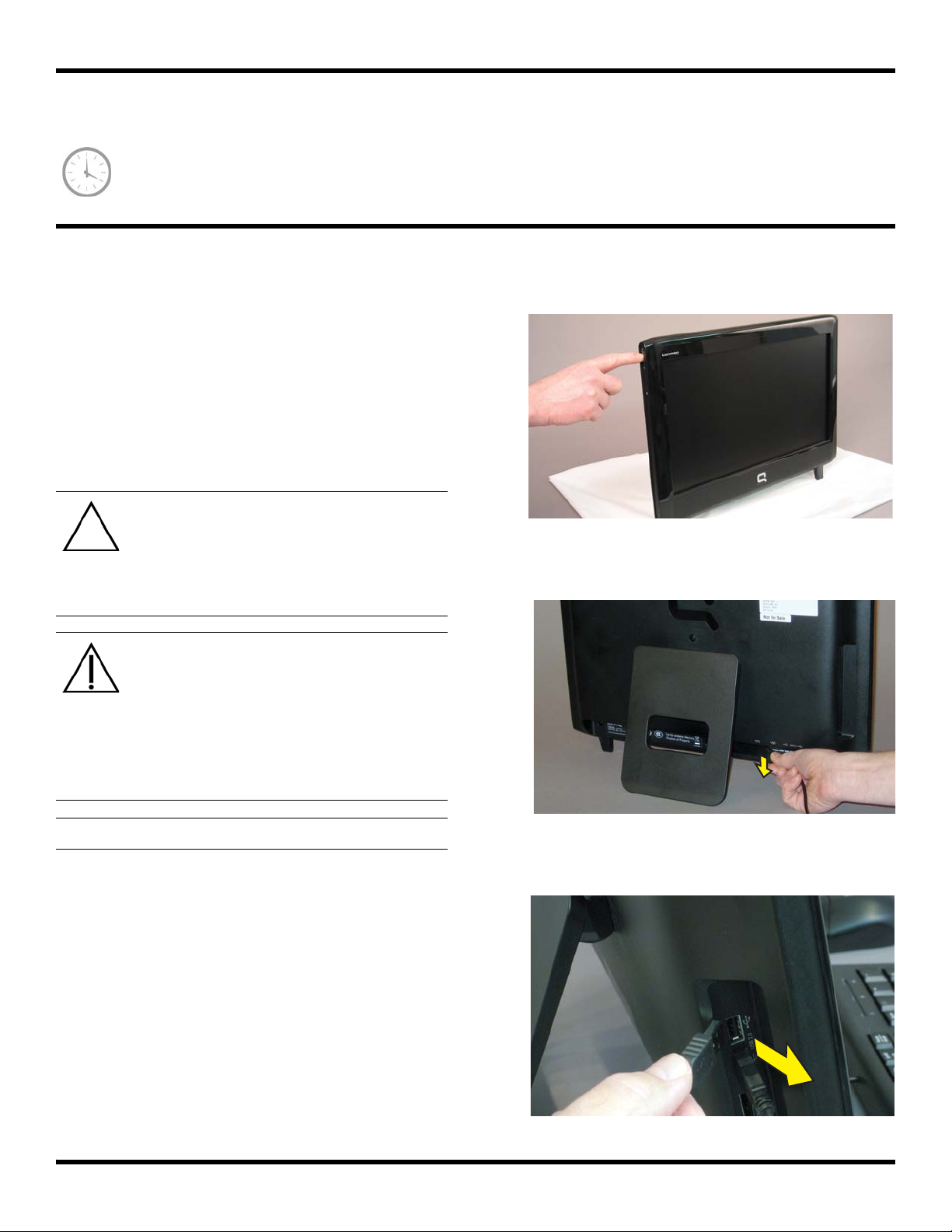
5 Set down a blanket, towel, or other soft cloth on a firm
surface, to protect the screen from scratches or other
damage. Place the computer face-down on the soft
surface.
Removing the CD/DVD Drive
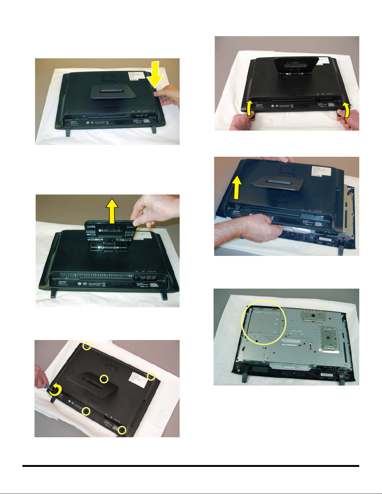
6 Lift the stand so that the bottom screw is accessible.
8 Lift the two feet to detach the back cover.
9 Lift the back cover off the computer.
7 Remove the six screws attaching the back cover to the
computer.
10 Locate the CD/DVD drive compartment on the back of
the computer.
603411-001 — Removing and Replacing a CD/DVD Drive 3
Page 6
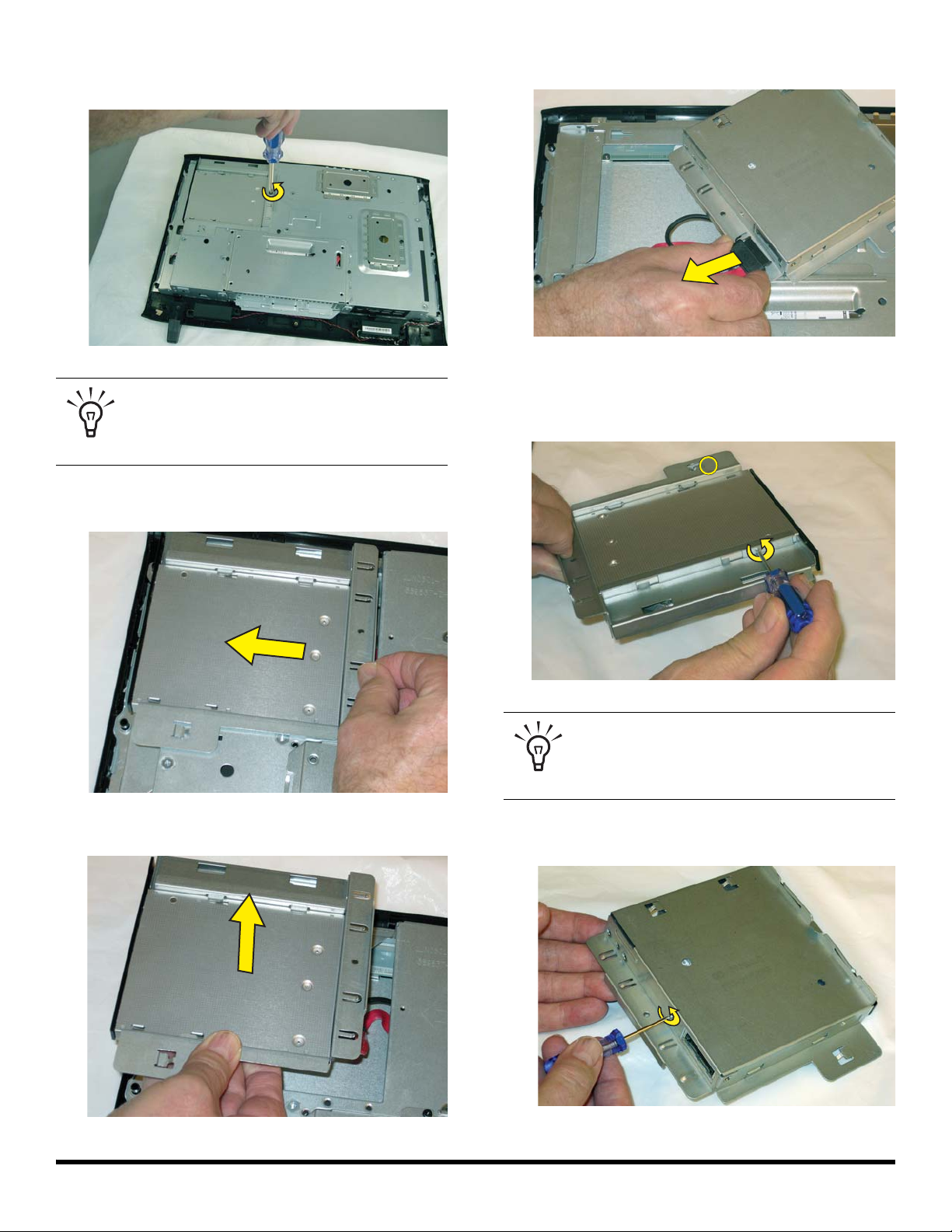
11 Use a #2 Phillips screwdriver to remove the screw that
secures the CD/DVD cover.
TIP: The screw is very small and can be lost
easily. Use caution when you remove it.
Work over a surface where you can retrieve
a screw if it falls.
12 Push the CD/DVD drive in the direction indicated by
the arrow engraved on the computer.
14 Disconnect the CD/DVD drive cable.
15 Use a #00 Phillips screwdriver to remove the screws
from the sides of the CD/DVD drive cage. There is one
screw located on each side.
13 Lift the CD/DVD drive out of the compartment.
TIP: The screws are very small and can be
lost easily. Use caution when you remove
them. Work over a surface where you can
retrieve a screw if it falls.
16 Use a #00 Phillips screwdriver to remove the screw at
the back of the CD/DVD drive cage.
4 603411-001 — Removing and Replacing a CD/DVD Drive
Page 7
17 Slide the CD/DVD drive forward to remove it from the
cage.
Installing a New CD/DVD Drive
1 Insert the new CD/DVD drive into the cage. Orient the
CD/DVD drive so that the connection for the cable
aligns with the opening at the rear of the cage.
2 Align the screw holes on the CD/DVD drive with the
screw holes on the cage.
3 Insert and tighten the screw on the back of the
CD/DVD cage.
603411-001 — Removing and Replacing a CD/DVD Drive 5
Page 8
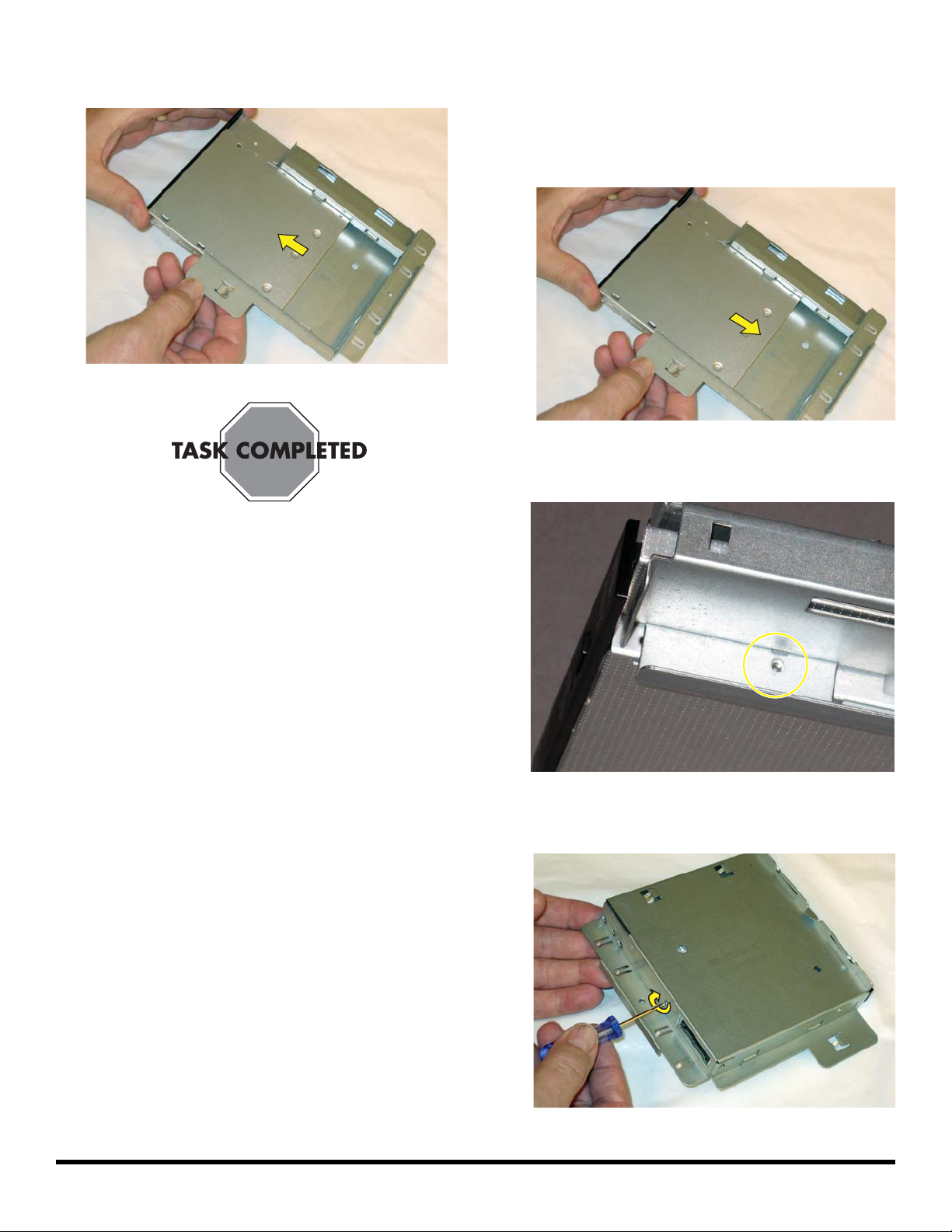
4 Insert and tighten the screw at the sides of the
CD/DVD cage.
TIP: Do not over-tighten these screws. It is
easy to strip the screw heads.
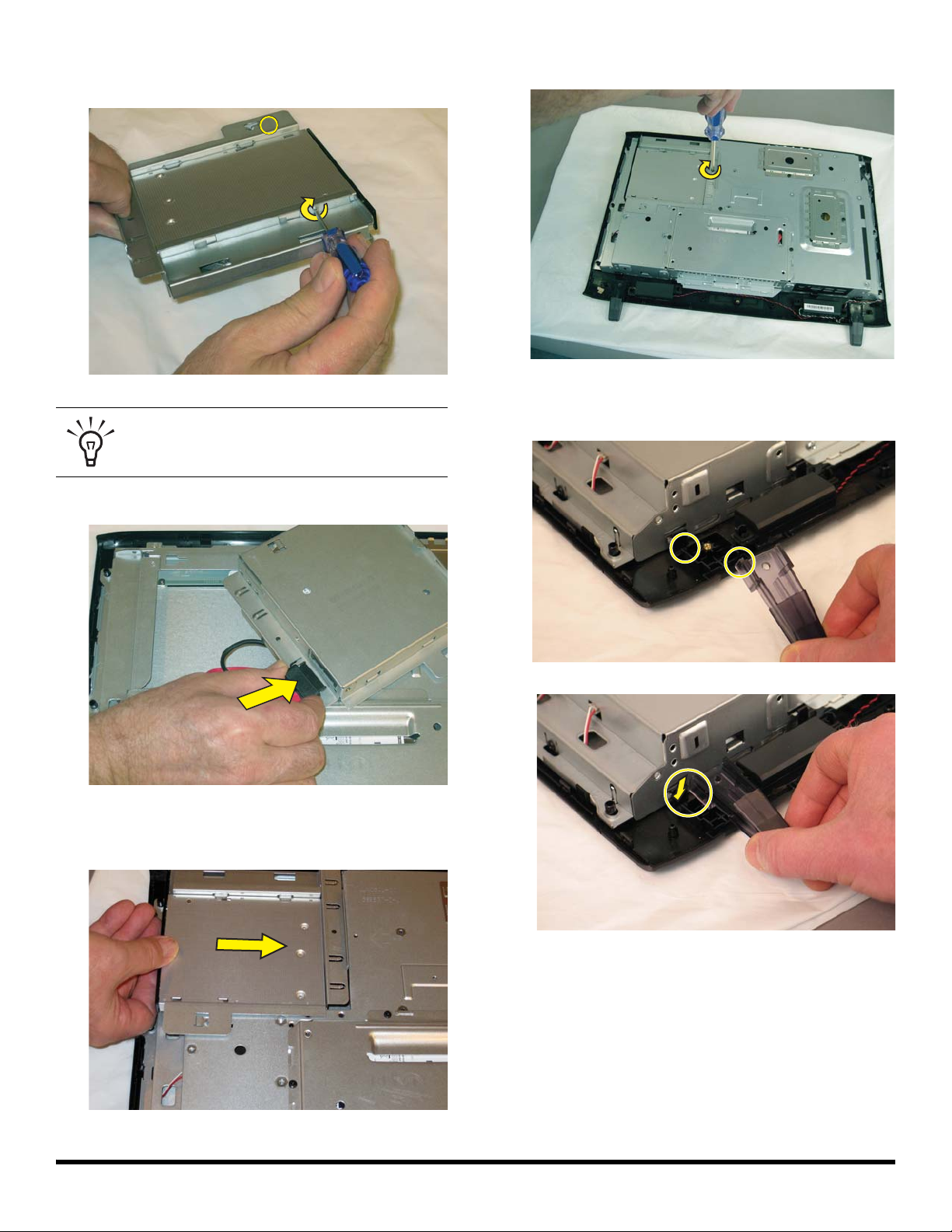
5 Connect the cable to the rear of the CD/DVD drive.
7 Replace the CD/DVD drive cover screw.
8 Before replacing the back cover, make sure the two
computer feet are properly positioned in place.
6 Insert the CD/DVD drive cage, sliding it forward until
the screw holes on the cage and computer align.
6 603411-001 — Removing and Replacing a CD/DVD Drive
Page 9
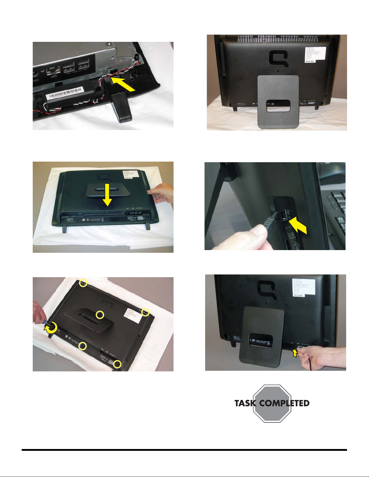
9 Ensure the wire at the bottom of the computer clears
the foot.
12 Return the computer to the upright position.
I
10 Position the back cover over the back of the computer
and snap into place.
11 Replace the six screws on the back cover.
13 Reconnect any cables that were disconnected for this
procedure.
14 Plug the power cord into the bottom of the computer.
I
603411-001 — Removing and Replacing a CD/DVD Drive 7
Page 10

Removing and Replacing a Hard Disk Drive
Page 11

Removing and Replacing a Hard Disk Drive
10 – 15 MINUTES
Before you begin
Observe the following requirements before removing and
replacing the hard disk drive.
IMPORTANT: A hard disk drive is extremely sensitive to
shock and impact. Do not bang or drop it. Do not touch
the circuit board. Static electricity can damage the drive.
Tools Needed
Magnetic-tip Phillips screwdriver #2
CAUTION: Static electricity can damage
the electronic components inside the
computer. Discharge static electricity by
touching the metal cage of the computer
before touching any internal parts or
electronic components.
WARNING:
2 Shut down the computer.
3 Unplug the computer by disconnecting the power cord
from the bottom of the computer.
Never open the cover with the
power cord attached or power
applied. You may damage your
computer.
Avoid touching sharp edges
inside the computer.
IMPORTANT: Computer features may vary by model.
4 Unplug all attached cables from the side and bottom
of the computer.
Computer Preparation
1 Remove any media (CD, DVD, and memory cards)
from the computer.
9 603411-001 — Removing and Replacing a Hard Disk Drive
Page 12

5 Set down a blanket, towel, or other soft cloth on a firm
surface, to protect the screen from scratches or other
damage. Place the computer face-down on the soft
surface.
8 Grasp each foot between the thumb and index finger.
Press the top of the foot down with your thumb while
pulling the bottom of the foot up with your finger. This
releases the back cover.
Removing the Hard Disk Drive
6 Lift the stand so that the bottom screw is accessible.
7 Remove the six screws attaching the back cover to the
computer.
9 Lift the back cover off the computer.
10 Locate the hard disk drive compartment on the back of
the computer.
10 603411-001 — Removing and Replacing a Hard Disk Drive
Page 13

11 Use a #2 Phillips screwdriver to remove the three
screws that secure the hard disk drive.
TIP: The screws are very small and can be
lost easily. Use caution when you remove
them. Work over a surface where you can
retrieve a screw if it falls.
12 Insert a finger or thumb into the opening and lift the
hard disk drive up and out of the computer, as shown
in the engraving on the hard drive cage.
14 Remove the screws on one side of the hard disk drive
cage.
15 Remove the hard disk drive from the cage.
13 Turn the hard disk drive over and disconnect the cable
connector from the back of the hard disk drive.
603411-001 — Removing and Replacing a Hard Disk Drive 11
Page 14

Installing a New Hard Disk Drive
NOTE: The replacement hard drive may not look exactly
the same as the original drive due to different
manufacturers or models. Hewlett-Packard always provides
quality parts that meet or exceed your original computer
specifications.
1 Insert the new hard disk drive into the cage. Make
sure that the hard drive is inserted with the label facing
up.
3 Replace and tighten the two screws on one side of the
cage.
4 Replace and tighten the screws on the other side of the
cage.
2 Align the hard disk drive screw holes with the screw
holes on the hard drive cage.
5 Turn the hard drive cage over and reconnect the cable
connector to the back of the hard disk drive.
12 603411-001 — Removing and Replacing a Hard Disk Drive
Page 15

6 Slide the cable beneath the cable retainer.
7 Ensure the lower bracket is in place before replacing
the hard disk drive cage into the computer.
9 Replace the screws securing the hard disk drive cage
to the computer.
10 Before replacing the back cover, make sure the two
computer feet are properly positioned in place.
8 Make sure that the slots on the bottom of the cage line
up with the tabs on the bottom of the hard drive bay
and push the hard drive cage into the bay. If the drive
gets stuck, push the cage gently until it moves into
place.
603411-001 — Removing and Replacing a Hard Disk Drive 13
Page 16

11 Ensure the wire at the bottom of the computer clears
the foot.
12 Position the back cover over the back of the computer
and snap into place.
14 Return the computer to the upright position.
15 Reconnect any cables that were disconnected for this
procedure.
13 Replace the six screws on the back cover.
16 Plug the power cord into the bottom of the computer.
14 603411-001 — Removing and Replacing a Hard Disk Drive
Page 17

Installing Memory
Page 18

Installing Memory
5 – 10 MINUTES
Before You Begin
Observe the following requirements installing memory
cards.
Tools Needed
Magnetic-tip Phillips screwdriver #2
CAUTION: Static electricity can damage
the electronic components inside the
computer. Discharge static electricity by
touching the metal cage of the computer
before touching any internal parts or
electronic components.
WARNING:
Never open the cover with the
power cord attached or power
applied. You may damage your
computer.
Avoid touching sharp edges
inside the computer.
2 Shut down the computer.
3 Unplug the computer by disconnecting the power cord
from the bottom of the computer.
IMPORTANT: Computer features may vary by model.
Computer Preparation
1 Remove any media (CD, DVD, and memory cards)
from the computer.
4 Unplug all attached cables from the side and bottom
of the computer.
16 603411-001 —Installing Memory
Page 19

5 Set down a blanket, towel, or other soft cloth on a firm
surface, to protect the screen from scratches or other
damage. Place the computer face-down on the soft
surface.
Installing the Memory
6 Lift the stand so that the bottom screw is accessible.
8 Grasp each foot between the thumb and index finger.
Press the top of the foot down with your thumb while
pulling the bottom of the foot up with your finger. This
releases the back cover.
9 Lift the back cover off the computer.
7 Remove the six screws attaching the back cover to the
computer.
10 Locate the memory compartment on the back of the
computer.
603411-001 — Installing Memory 17
Page 20

11 Use a #2 Phillips screwdriver to remove the screw that
secures the memory cover.
14 Holding the card by its edges, slide it all the way into
the slot.
TIP: The screw is very small and can be lost
easily. Use caution when you remove it.
Work over a surface where you can retrieve
a screw if it falls.
12 Slide the memory cover in the direction indicated by
the arrow engraved on the computer. Remove the
cover.
13 Orient the new card so that the notch on the edge of
the card faces forward.
15 Make sure the card is pressed all the way into the
socket and then gently push down on the card to snap
it into place.
16 Slide the memory cover into place.
18 603411-001 —Installing Memory
Page 21

17 Replace the memory cover screw.
18 Before replacing the back cover, make sure the
computer feet are properly positioned in place.
19 Ensure the wire at the bottom of the computer clears
the foot.
20 Position the back cover over the back of the computer
and snap into place.
21 Replace the six screws on the back cover.
603411-001 — Installing Memory 19
Page 22

22 Return the computer to the upright position.
23 Reconnect any cables that were disconnected for this
procedure.
Troubleshooting
If the computer displays a memory error after you have
turned it back on, check the following:
Turn the computer off and unplug the power cord, then
open up the memory compartment and make sure the
memory card is firmly seated. To install it correctly,
make sure it inserted all the way into the compartment
and then push down on it to snap it into place.
Verify that the memory installed is compatible with this
computer.
SO-DIMM modules must meet the following
requirements:
200-pin DDR2-DIMM
PC2-4200 (533 MHz) DDR2-SDRAM or
PC2-5300 (667 MHz) DDR2-SDRAM
Unbuffered, non-ECC (64-bit) DIMMs
1.8 V memory only
4.0 GB maximum installable memory. Actual
available memory that can be used in Windows
may be less.
24 Plug the power cord into the bottom of the computer.
Because the memory uses dual channels, you
should use the same DIMM type for both sockets.
20 603411-001 —Installing Memory
Page 23

Removing and Replacing a Stand
Page 24

Removing and Replacing a Stand
5 – 10 minutes
Before You Begin
Observe the following requirements before removing and
replacing the stand.
Tools Needed
Magnetic-tip Phillips screwdriver #2
CAUTION: Static electricity can damage
the electronic components inside the
computer. Discharge static electricity by
touching the metal cage of the computer
before touching any internal parts or
electronic components.
WARNING:
Never open the cover with the
power cord attached or power
applied. You may damage your
computer.
2 Shut down the computer.
3 Unplug the computer by disconnecting the power cord
from the bottom of the computer.
Avoid touching sharp edges
inside the computer.
IMPORTANT: Computer features may vary by model.
4 Unplug all attached cables from the side and bottom
Computer Preparation
1 Remove any media (CD, DVD, and memory cards)
from the computer.
of the computer.
22 603411-001 — Removing and Replacing a Stand
Page 25

5 Set down a blanket, towel, or other soft cloth on a firm
surface, to protect the screen from scratches or other
damage. Place the computer face-down on the soft
surface.
Removing the Stand
6 Lift the stand so that the bottom screw is accessible.
8 Grasp each foot between the thumb and index finger.
Press the top of the foot down with your thumb while
pulling the bottom of the foot up with your finger. This
releases the back cover.
9 Lift the back cover off the computer.
7 Remove the six screws attaching the back cover to the
computer.
10 Push the stand down so that it lays flat against the
back cover.
603411-001 — Removing and Replacing a Stand 23
Page 26

11 Turn the back cover over and use a #2 Phillips
screwdriver to remove the two screws that secure the
stand.
TIP: The screws are very small and can be
lost easily. Use caution when you remove
them. Work over a surface where you can
retrieve a screw if it falls.
12 Slide the stand out of the back cover.
Installing a New Stand
1 Insert the new stand into the opening on the back
cover.
13 Remove the stand.
2 Align the screw holes on the stand with the screw holes
on the back cover.
24 603411-001 — Removing and Replacing a Stand
Page 27

3 Insert and tighten the screws to secure the stand to the
back cover.
5 Ensure the wire at the bottom of the computer clears
the foot.
4 Before replacing the back cover, make sure the two
computer feet are properly positioned in place.
6 Position the back cover over the back of the computer
and snap into place.
7 Lift the stand so that the bottom screw hole is visible.
603411-001 — Removing and Replacing a Stand 25
Page 28

8 Replace the six screws on the back cover.
*603411-001*
*603411-001*
9 Return the computer to the upright position.
I
11 Plug the power cord into the bottom of the computer.
I
10 Reconnect any cables that were disconnected for this
procedure.
Copyright © 2010 Hewlett-Packard Development Company, L.P.
The information contained herein is subject to change without notice.
Version: 1.0
Printed in
 Loading...