

Page 1
HP Compaq Business Desktop
dx2200 Microtower Models
Illustrated Parts Map
Celeron and Pentium Processors
© 2006 Hewlett-Packard Development Company, L.P.
HP and the HP logo are trademarks of Hewlett-Packard
Intel and Celeron are US registered trademarks of Intel
Corporation. All other product names mentioned herein
Development Company, L.P.
may be trademarks of their respective companies.
HP shall not be liable for technical or editorial errors or
omissions contained herein. The information in this
document is provided “as is” without warranty of any kind
and is subject to change without notice. The warranties for
HP products are set forth in the express limited warranty
statements accompanying such products. Nothing herein
should be construed as constituting an additional
warranty.
1st Edition, March 2006
Document Part Number 415607-001
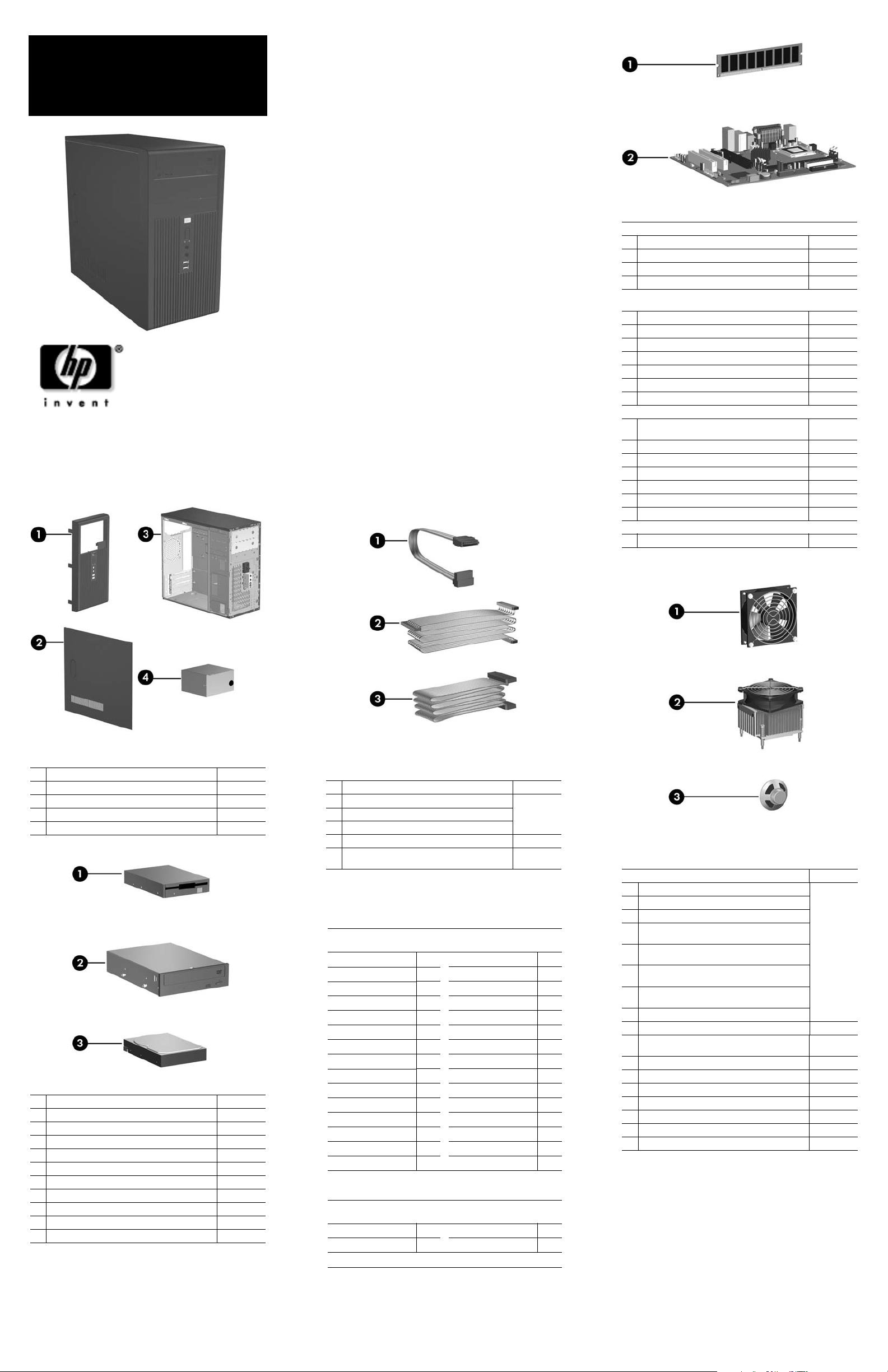
Standard and Optional Boards
Memory modules
1 256 MB, PC2-5300
* 512 MB, PC2-5300
* 1 GB, PC2-5300
2 System board with alcohol pad and thermal grease
Intel Celeron D Processors, 533 MHz FSB, 256 KB, with alcohol pad
and thermal grease
* #336, 2.8GHz, E0 stepping
#346, 3.06 GHz, E0 stepping
#331, 2.66 GHz, G-1 stepping
* #336, 2.8 GhHz, G-1 stepping
* #341, 2.93 GHz, G-1 stepping 405692-001
* #346, 3.06 GHz, G-1 stepping 405693-001
* #351, 3.2 GHz, G-1 stepping
Intel Pentium Processors with alcohol pad and thermal grease
* #524, 3.06 GHz, 533 MHz FSB, 1MB, non-hyper-
threading
#524, 3.06 GHz, 533 MHz FSB, Mainstream
* #521, 2.8 GHz, 800 MHz FSB, Mainstream 394643-001
#620, 2.8 GHz, 800 MHz FSB, Mainstream 418627-001
* #630, 3.0 GHz, 800 MHz FSB, Mainstream 392273-001
* #650, 3.2 GHz, 800 MHz FSB, Mainstream
* #650, 3.4 GHz, 800 MHz FSB, Mainstream
Other boards
* Graphics PCIe, 128 MB, FH
* Not shown
396519-001
396520-001
398038-001
410716-001
416337-001
416338-001
391940-001
391941-001
382503-001
412985-001
418626-001
384786-001
384787-001
398332-001
System Unit
1 Front bezel without bezel blank 410724-001
2 Access panel 410723-001
3 Chassis not spared
4 Power supply, non-PFC 410719-001
4 Power supply, PFC 410720-001
Mass Storage Devices
1 Diskette drive, 3.5-inch, with mounting screws 392415-001
2
48X CD-ROM drive 397130-001
* 52X CD-ROM drive 413522-001
* 48X/32/X48X CD-RW drive 395272-001
* 48X/32X/48X+16X CD-RW/DVD-ROM drive 405425-001
* 16/48X DVD ROM Drive 405761-001
* 16X DVD +/- RW 405760-001
3
40-GB\7200 RM SATA hard drive, 1.5 Gb/s 416737-001
*
80-GB\7200 RPM SATA hard drive, 3.0 Gb/s 391945-001
*
160-GB\7200 RPM SATA hard drive, 3.0 Gb/s 391741-001
*
250-GB\7200 RPM SATA hard drive, 3.0 Gb/s 391937-001
*Not shown
Cables
Miscellaneous cable kit, includes: 410725-001
1 SATA HDD cable(K1D-1008060-M78)
2 ODD cable (K12-1080104-M78)
3 Diskette drive cable (385981-002)
* Front USB cable with mounting screw 416164-001
* Power switch with cable and switch mounting
bracket
*Not shown
Keyboards (not illustrated)
PS/2, Basic
USB, Basic
Belgian -181 LA Spanish -161
BHCSY* -B41 Norwegian -091
Brazilian Portuguese -201
Czech -221 Portuguese -131
Danish -081
Finnish -351 Slovakian -231
French -051 Spanish -071
French Arabic -DE1 Swedish -101
French Canadian -121 Swiss -111
German -041 Taiwanese -AB1
Hebrew -BB1 Thai -281
Hungarian -211 Turkish -141
International -B31
Italian -061 U.S. -001
Korean (Hanguel) -AD1 U.K. -031
*Bosnia-Herzegovina, Croatia, Slovenia, and Yugoslavia
PS/2, Basic, 105 key
USB, Basic, 105 key
Arabic* -171 Russian -251
Greek -151
*Only available in PS/2 configuration (396215-xxx)
382925-xxx
382926-xxx
PRC -AA1
Romanian -271
Ukranian -BD1
396215-xxx
396217-xxx
416163-001
Miscellaneous Parts
Miscellaneous parts kit, includes: 410717-001
* 3.5” Diskette drive bezel (414218-001)
* 3.5” Bezel blank (414219-001)
* 5.25” Bezel blank (166775-001)
* #6-32 x .187 Taptite, hitop screw with serrations (6
ea) (192308-003)
#6-32 x .187 Taptite, hitop screw with serrations (6
ea) (192308-001)
* #6-32 x .250 Taptite, hitop screw with captive flat
washer (2 ea) (114399-067-001)
* M3 x 5 mm Taptite hitop screw with serrations (4
ea) (247348-001)
* Slot cover (391106-0010 (2 ea)
1 Chassis fan with mounting screws 410721-001
2 Heatsink with alcohol pad and factory-applied ther-
mal grease
* Mouse, PS2, scroll type 390937-001
3 Internal speaker 410722-001
* Mouse, USB, scroll type 390939-001
* Mouse, optical 390938-001
* Battery, real-time clock 153099-001
* Foot (4 ea) 370708-001
* DVI-I to VGA adapter 202997-001
*Not shown
410718-001
Page 2
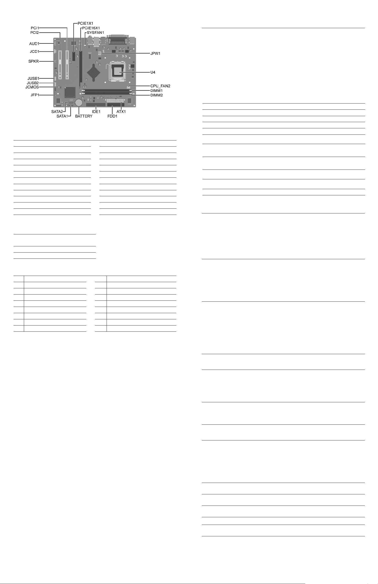
System Board Connectors and Jumpers (position of some untitled components may vary in location)
AT X1 Main power JUSB1 Front USB
AUD1 Front audio JUSB2 Internal USB for media reader
BATTERY RTC battery PCIE16X1 PCIe X16
CPU FAN Processor fan PCIE1X1 PCIe X1
DIMM1 Memory module 1 PCI1 PCI slot 1
DIMM2 Memory module 2 PCI2 PCI slot 2
FDD1 Diskette drive SATA1 SATA primary
IDE1 Optical drive SATA2 SATA secondary
JCD1 CD audio SPKR speaker
JCMOS CMOS SYSFAN1 Chassis fan
JPFP1 Front power switch/LED U4 Processor
JPW1 CPU main power
CMOS
Jumper
Status
Normal 2-3 Default
Clear 1-2 leave on for 5 seconds
System Hardware Interrupts
IRQ
0
1
2
3
4
5
6
7
Setting
System Function IRQ System Function
Timer Interrupt 8 Real-Time Clock
Keyboard 9 Unused
Interrupt Controller Cascade 10 Unused, available for PCI
Serial Port (COM B) 11 Unused, available for PCI
Serial Port (COM A) 12 Mouse
Unused, available for PCI 13 Coprocessor
Diskette Drive 14 Primary ATA (IDE) Controller
Parallel Port (LPT 1) 15 Secondary ATA (IDE) Controller
Notes
Clearing CMOS
The computer's configuration (CMOS) may occasionally be corrupted. If it is, it is necessary to clear the CMOS
memory using by performing the following procedure:
CAUTION: The power cord must be disconnected from the power source before changing the jumper
Ä
setting. (NOTE: All LEDs on the board should be OFF). Failure to do so may damage the system board
1. Turn off the computer and any external devices, then disconnect the power cord from the power outlet.
2. Remove the access panel.
3. Locate jumper CMOS and move the jumper from pins 2-3 to pins 1-2.
4. Leave the jumper on pins 1-2 for 5 seconds.
5. Move the jumper back to pins 2-3.
6. Replace the access panel.
7. Connect the power cord to the power outlet.
8. Turn on the computer, allow it to start.
Diagnostic LEDs
LED Color LED Activity State/Message
Power Green On Computer on
Power Green 1 blink every 2 seconds (S1) Normal Suspend Mode
Power Green 1 blink every 2 seconds (S3) Suspend to RAM
Power Clear Off (S5) Computer off
Power Green Glows for 3 seconds followed by
Power Green 1 blink every second for 5
Power Green 1 blink every second for 6
None None No LED but rapidly inclining
None None No LED but rapidly declining
Hard Drive Green Blinking Hard drive activity
Computer Setup (F10) Utility Features (not all features may be available)
Product Name
SKU Number
Processor Type
Processor speed
CPU ID/Patch ID
System
Information
Standard CMOS
Features
Advanced BIOS
Features
Advanced
Chipset Features
Integrated
Peripherals
Power
Management
Setup
PnP/PCI
Configuration
PC Health Status
Load Optimized
Defaults
Set Supervisor
Password
Set User
Password
Save & Exit Setup
Exit Without
Saving
Note: See Computer Setup (F10) Utility Guide on the Documentation Library CD.
Cache Size
Memory Size
System ROM
Integrated MAC Address
UUID
System Serial Number
Asset Tracking Number
Asset Tag Number
Set Date
Set Time
PATA Controller
PATA Channel 0 Master
PATA Channel 0 Slave
SATA Controller
SATA Channel 1 Master
SATA Channel 2 Master
Floppy Drive Controller
Drive A
Halt On
POST Delay
Device Boot Disabling
F9 Boot Menu
Removable Device Boot Priority
Hard Disk Boot Sequence
Optical Drive Boot Sequence
Network Boot Sequence
First through Fourth Boot Devices
Boot Up NumLock Status
Security Option
APIC Mode
MPS Version Control for OS
BIOS Write Protection
Execute disable bit
Enhanced Intel SpeedStep Technology
Hyper-Threading Technology
UMA Frame Buffer
Init Display First (VGA Setting)
Surroundview
AutoDetect PCI CLK (VGA Setting)
Onboard HD Audio
OnChip USB Controller
USB Legacy Support
Onboard LAN
Onboard LAN Boot ROM
Onboard Serial Port
Onboard Parallel Port
Parallel Port Mode
ECP Mode Use DMA
After AC Power Loss
ACPI Suspend type
External Modem S5 Wake-up
RTC Alarm Resume
Date (of Month) Alarm
Resume Time (hh:mm:ss)
Reset Configuration Data
Resources Controlled By
IRQ Resources
Maximum Payload Size
System Fan Fail Check
Smart Fan Function
Current CPU Temperature
Current System Temperature
Current CPU Fan Speed
Current System Fan Speed
Vcore
+12V
VCC5
+3.3V
VBAT (V)
3VSB (V)
a 1 second pause.
seconds, then 2 second pause.
5 beeps.
seconds, then 2 second pause.
6 beeps.
beeps
beeps
CPU thermal shutdown
No memory installed or improperly installed
(pre-video memory error)
Graphics card error (pre-video graphics error)
Incorrect system password.
Correct system password.
 Loading...