

Page 1
HP Compaq Business PC
dx2100 ST Series Personal
Computer
Illustrated Parts Map
Slim Tower Form Factor
© 2005 Hewlett-Packard Development Company, L.P.
HP and the HP logo are trademarks of Hewlett-Packard
All other product names mentioned herein may be
Development Company, L.P.
trademarks of their respective companies.
HP shall not be liable for technical or editorial errors or
omissions contained herein. The information in this
document is provided “as is” without warranty of any kind
and is subject to change without notice. The warranties for
HP products are set forth in the express limited warranty
statements accompanying such products. Nothing herein
should be construed as constituting an additional
warranty.
First Edition, September 2005
Document Number
376222-001
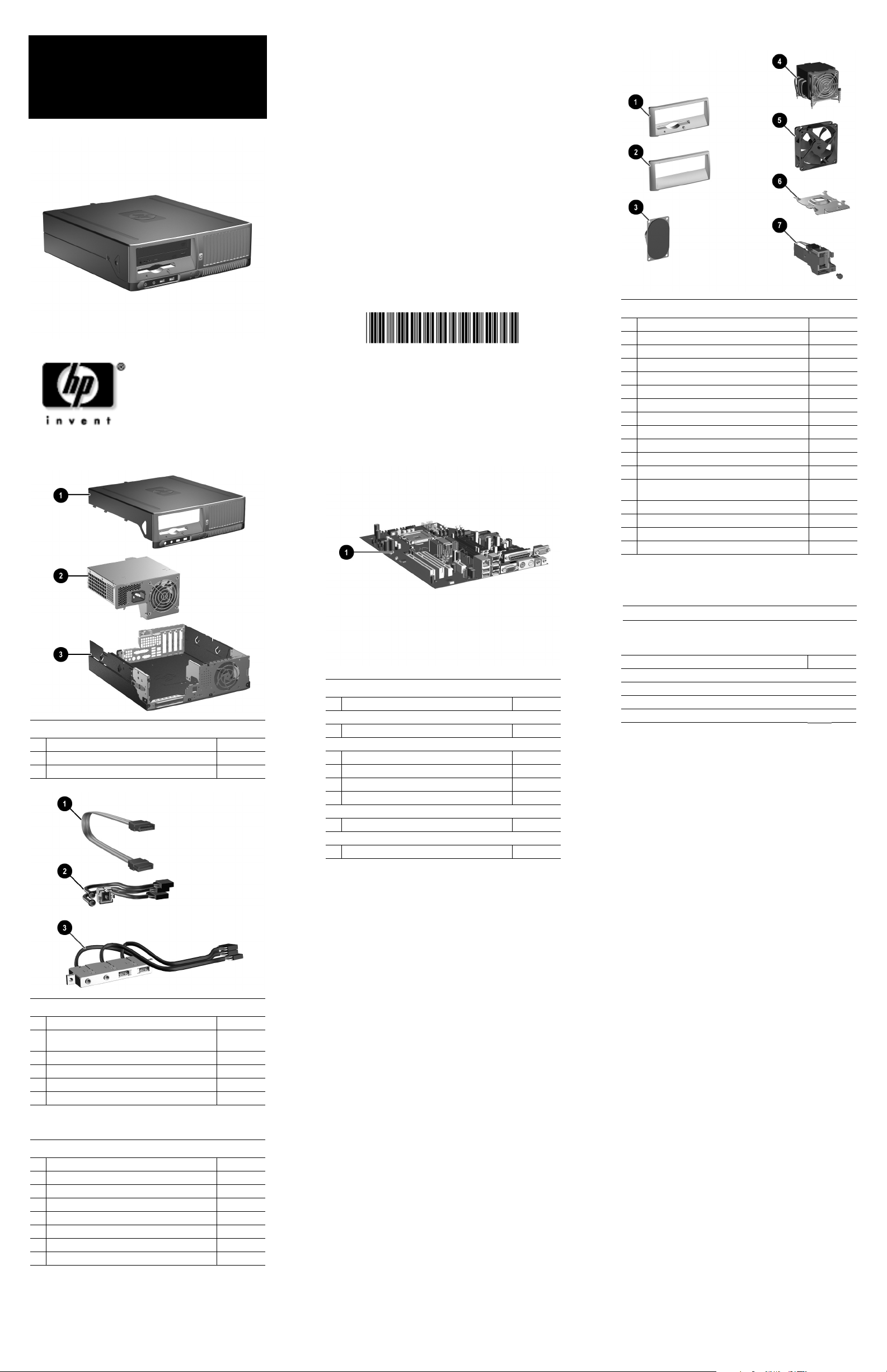
Miscellaneous Parts
1 CD drive bezel with diskette drive slot 370501-001
2 CD drive bezel without diskette drive 367852-001
3 Speaker 368084-001
4 Heatsink with thermal grease and alcohol pad 382024-001
5 Chassis fan 392412-001
Heatsink duct baffle 375514-001
6 Heatsink retention plate 393609-001
* Heatsink retention plate thumbscrew 393610-001
7 Solenoid lock with cable 393602-001
* Tower stand 393604-001
* Hood sensor 393603-001
* Mouse, 2-Button, PS/2 with scroll wheel 390937-001
* Power switch holder with LED holders (use with
392410-001 switch)
* Foot kit, oval and round (4 ea) 370708-001
* Real-time-clock battery 153099-001
* Port control cover 367856-001
* Second serial port (low profile) 393601-001
*Not shown
370857-001
System Unit
1 Computer cover assy with front bezel and no inserts 393612-001
2 Power supply 403235-001
3 Chassis assembly not spared
Standard and Optional Boards
1
System board with alcohol pad and thermal grease 380725-001
Memory Modules
* 256 MB/533 MHz FSB/PC2-4200
Intel Pentium 4 Processors with alcohol pad and thermal grease
* 2.8 GHz\800 MHz FSB, 1MB cache, 521 394643-001
* 3.0 GHz\800 MHz FSB, 2MB cache, 630 392273-001
* 3.2 GHz\800 MHz FSB, 2MB cache, 640 384786-001
* 3.4 GHz\800 MHz FSB, 2MB cache, 650 384787-001
Intel Celeron D Processors with alcohol pad and thermal grease
* 2.66 GHz/533 MHz FSB, 256 KB cache, 331 391940-001
Other Cards
* 1394, LP bracket 361551-001
*Not shown
LP= Low profile mounting bracket
393392-001
Keyboards (not illustrated)
PS/2, Basic, Japanese 382925-291
Miscellaneous Screw Kit (not illustrated)
Miscellaneous screw kit 393956-001
6-32x.250 TF, HI/TP W/SERR, 6 ea (192308-001)
6-32 Tamper resistant, 2 ea (296769-002)
Plastite, Flathead, Phillips, 4 ea (247481-001)
Plastite 8X5/16L, 2 ea (334248-001)
Cables
1
SATA hard drive cable, 19.5” 391739-001
2
Power switch/LED cable (use switch holder
370857-001)
Serial port cable assembly, 2.65” 393605-001
*
3
Front I/O device with cable (USB + audio) 393606-001
* Diskette drive cable 393608-001
* IDE optical drive cable 393607-001
*Not shown
Mass Storage Devices (not illustrated)
40 GB\7200 RPM SATA hard drive 365555-001
80 GB\7200 RPM SATA hard drive 345713-001
160 GB\7200 RPM SATA hard drive 345712-001
250 GB\7200 RPM SATA hard drive 393303-001
Diskette drive with mounting screws 333505-001
48X CD-ROM drive with mounting screws 326773-001
16X DVD+R/+RW Drive w/double density write 381417-001
16X DVD+/-RW with LightScribe (DL/DF) drive 390882-001
395626-001
Page 2
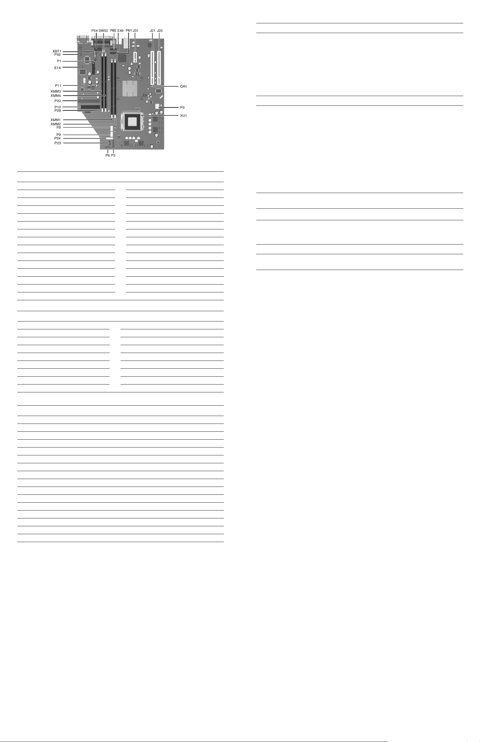
System Board Connectors and Jumpers (position of some untitled components may vary in location)
CR1 5CV Aux power LED P23 Front audio
E14 Boot block P24 USB connector, front panel
E49 Password jumper P29 SCSI LED connector
J20 PCI slot 1
J21 PCI slot 2 P54 Serial port “A”
J31 PCI Express x1
P1 Main power (24 pin) P61 Secondary serial ATA (SATA) port
P3 Processor VccP Power 12V (6 pin) SW50 CMOS button
P5 Main power switch/LED XBT1 Battery
P6 Internal chassis speaker XMM1 Memory socket
P8 Primary chassis fan XMM2 Memory socket
P9 Secondary chassis fan XMM3 Memory socket
P10 Diskette drive XMM4 Memory socket
P11 Aux audio in XU1 Microprocessor
P20 IDE
P52 Serial port “B”
P60 Primary serial ATA (SATA) port
Clearing CMOS
The computer's configuration (CMOS) may occasionally be corrupted. If it is, it is necessary to clear the CMOS
memory using switch SW50.
To clear and reset the configuration, perform the following procedure:
1. Turn off the computer and any external devices, and disconnect the power cord from the power outlet.
CAUTION: You must disconnect the power cord from the power source before pushing the Clear CMOS
Ä
Button (NOTE: All LEDs on the board should be OFF). Failure to do so may damage the system board.
2. Remove the access panel.
3. Press the CMOS button located on the system board.
4. Replace the access panel.
5. Turn the computer on and run F10 Computer Setup (Setup utility) to reconfigure the system.
Disabling or Clearing the Power-On and Setup Passwords
1. Turn off the computer and any external devices, and disconnect the power cord from the power outlet.
2. Remove the access panel.
3. Locate the header and jumper labeled E49.
4. Remove the jumper from pins 1 and 2. Place the jumper over pin 2 only to avoid losing it.
5. Replace the access panel.
6. Plug in the computer and turn on power. Allow the operating system to start.
NOTE: Placing the jumper on pin 2 clears the current passwords and disables the password features.
7. To re-enable the password features, repeat steps 1-3, then replace the jumper on pins 1 and 2.
8. Repeat steps 5-6, then establish new passwords.
Refer to the Desktop Management Guide and the Computer Setup (F10) Utility Guide for instructions on
establishing new passwords
Computer Setup (F10) Utility Features (not all features may be available)
File
Storage
Security
Power
Advanced
Note: See the Computer Setup (F10) Utility Guide on the Documentation and Diagnostics CD.
System Information
About
Set Time and Date
Device Configuration
Storage Options
Setup Password
Power-On Password
Password Options
Smart Cover
Embedded Security
OS Power Management Hardware Power Management Thermal
Power-On Options
BIOS Power On
Onboard Devices
Replicated Setup
Default Setup
Apply Defaults and Exit
DPS Self-Test
Boot Order
Drivelock Security
Data Execution Prevention
Master Boot Record Security
Save Master Boot Record
Restore Master Boot Record
PCI Devices
Bus Options
Ignore Changes and Exit
Save Changes and Exit
Device Security
Network Service Boot
System IDs
Device Options
PCI VGA Configuration
System Hardware Interrupts
System Function IRQ System Function
IRQ
Timer Interrupt 8 Real-Time Clock
0
Keyboard 9 Unused
1
Interrupt Controller Cascade 10 Unused, available for PCI
2
Serial Port (COM B) 11 Unused, available for PCI
3
Serial Port (COM A) 12 Mouse
4
Unused, available for PCI 13 Coprocessor
5
Diskette Drive 14 Primary ATA (IDE) Controller
6
Parallel Port (LPT 1)
7
Computer Diagnostic LEDs (on front of computer)
LED Color LED/Beep Activity State/Message
Power Green On (S0) Computer on
Power Green 1 blink every 2 seconds (S1) Suspend Mode
Power Green 1 blink every 2 seconds (S3) Suspend to RAM
Power Clear Off (S4) Hibernation
Power Clear Off (S5) Computer off
Power Red* 2 blinks 1 second apart CPU thermal shutdown
Power Red* 3 blinks 1 second apart CPU not installed
Power Red* 4 blinks 1 second apart Power supply overload (crow bar)
Power Red* 5 blinks 1 second apart Defective or missing memory
Power Red* 6 blinks 1 second apart Defective or missing graphics
Power Red* 7 blinks 1 second apart System board failure (detected prior to video)
Power Red* 8 blinks 1 second apart Invalid ROM based on checksum
Power Red* 9 blinks 1 second apart System not fetching code
Power Red* 10 blinks 1 second apart System hang while loading an option ROM
Hard Drive Green Blinking Hard drive activity
*Blinking codes are repeated after a 2 second pause. Beeps stop after fifth iteration but LEDs continue until problem is
resolved.
 Loading...