

Page 1

Compaq Deskpro Workstation 300
Hardware Reference Guide
Page 2

Deskpro Workstation 300
Hardware Reference Guide
Page 3
Notice
© 2000 Compaq Computer Corporation. Except for use in connection with the accompanying
Compaq product, no part of this guide may be photocopied or reproduced in any form without
prior written consent from Compaq Computer Corporation.
COMPAQ, the Compaq logo, and Deskpro Registered in U.S. Patent and Trademark Office.
Microsoft, Windows, Windows NT, and Window 2000 Professional are trademarks of
Microsoft Corporation. Intel and Pentium are trademarks of Intel Corporation.
All other product names mentioned herein may be trademarks or registered trademarks of
their respective companies.
Compaq shall not be liable for technical or editorial errors or omissions contained herein. The
information in this guide is subject to change without notice. The warranties for Compaq
products are set forth in the express limited warranty statements accompanying such products.
Nothing herein should be construed as constituting an additional warranty.
The following words and symbols mark special messages throughout this guide:
WARNING:
to follow directions could result in bodily harm or loss of life.
CAUTION:
to follow directions could result in damage to equipment or
loss of information.
Text set off in this manner indicates that failure
Text set off in this manner indicates that failure
Compaq Deskpro Workstation 300
Hardware Reference Guide
First Edition (October 2000)
Part Number 212399-001
Compaq Computer Corporation
Page 4

chapter 1
Product Features
Standard Configuration Features............................................................................................. 1-1
Front Panel Components......................................................................................................... 1-2
Rear Panel Components .......................................................................................................... 1-3
I/O Panel Components ............................................................................................................1-4
System Board Components..................................................................................................... 1-5
Changing from a Minitower to a Desktop Configuration .......................................................1-6
Changing from a Desktop to a Minitower Configuration .......................................................1-9
Keyboard............................................................................................................................... 1-12
Easy Access Software...................................................................................................... 1-13
Reprogramming the Easy Access Buttons................................................................. 1-13
Locking and Unlocking the Easy Access Buttons ..................................................... 1-13
Easy Access Paper Icon Insert................................................................................... 1-13
Windows Logo Key......................................................................................................... 1-14
Special Mouse Functions....................................................................................................... 1-14
Serial Number Location........................................................................................................ 1-14
chapter 2
Hardware Upgrades
Installation Sequence............................................................................................................... 2-2
Removing the Workstation Access Panel................................................................................ 2-3
Removing the Front Bezel....................................................................................................... 2-4
Installing Additional Memory................................................................................................. 2-5
Installing and Removing RIMMs...................................................................................... 2-5
RIMM Socket Locations.............................................................................................. 2-5
Guidelines for RIMM Installation..................................................................................... 2-6
Installing RIMMs .............................................................................................................. 2-7
Removing RIMMs............................................................................................................. 2-8
Installing Additional Drives.................................................................................................... 2-9
Drive Bay Components ..................................................................................................... 2-9
Minitower Drive Bay Positions.................................................................................... 2-9
Desktop Drive Bay Positions..................................................................................... 2-10
Preparing for Drive Installation....................................................................................... 2-11
Removing the Bezel Blank ........................................................................................ 2-11
Installing a Drive............................................................................................................. 2-12
Installing a Hard Drive into a 3.5-inch Drive Bay..................................................... 2-12
Installing a Hard Drive into a 5.25-Inch Drive Bay................................................... 2-15
Removing a Drive............................................................................................................ 2-16
ONTENTS
C
Compaq Deskpro Workstation 300 Hardware Reference Guide iii
Page 5

Installing and Removing an Expansion Board...................................................................... 2-19
Identifying the PCI and AGP Expansion Sockets ........................................................... 2-19
Installing an Expansion Board......................................................................................... 2-20
Removing an Expansion Board....................................................................................... 2-21
appendix A
Specifications
appendix B
Hard Drive Installation
Using the Cable-Select Feature with Ultra ATA Devices.......................................................B-1
Guidelines for Installing Ultra ATA IDE Devices..................................................................B-2
SCSI Devices...........................................................................................................................B-2
Guidelines for Using SCSI Devices...................................................................................B-2
Guidelines for Installing SCSI Devices.............................................................................B-5
SCSI Cables.............................................................................................................................B-5
Using a SCSI Cable...........................................................................................................B-5
Using SCSISelect with SCSI Devices .....................................................................................B-6
appendix C
Battery Replacement
Procedure for Replacing the Battery.......................................................................................C-1
iv Contents
appendix D
Security Lock Provisions
Installing a Cable Lock ...........................................................................................................D-1
appendix E
Electrostatic Discharge
Preventing Electrostatic Damage ............................................................................................E-1
Grounding Methods ................................................................................................................E-2
appendix F
Routine Computer Care and Shipping Preparation
Routine Computer Care........................................................................................................... F-1
CD-ROM Drive Precautions ................................................................................................... F-2
Operation........................................................................................................................... F-2
Cleaning............................................................................................................................. F-2
Safety.................................................................................................................................F-2
Shipping Preparation...............................................................................................................F-3
......................................................................................................................................................I-1
Index
Page 6

chapter
RODUCT FEATURES
P
Standard Configuration Features
The Compaq Deskpro™ Workstation 300 is a minitower system that
can be easily converted to a desktop. Features may vary depending on
your model. For a complete listing of the hardware and software
installed in your workstation, run Compaq Diagnostics for Windows or
the INSPECT utility (available on some models). Instructions for using
these utilities are provided in the Troubleshooting Guide.
1
Compaq Deskpro Workstation 300 Hardware Reference Guide 1-1
Page 7
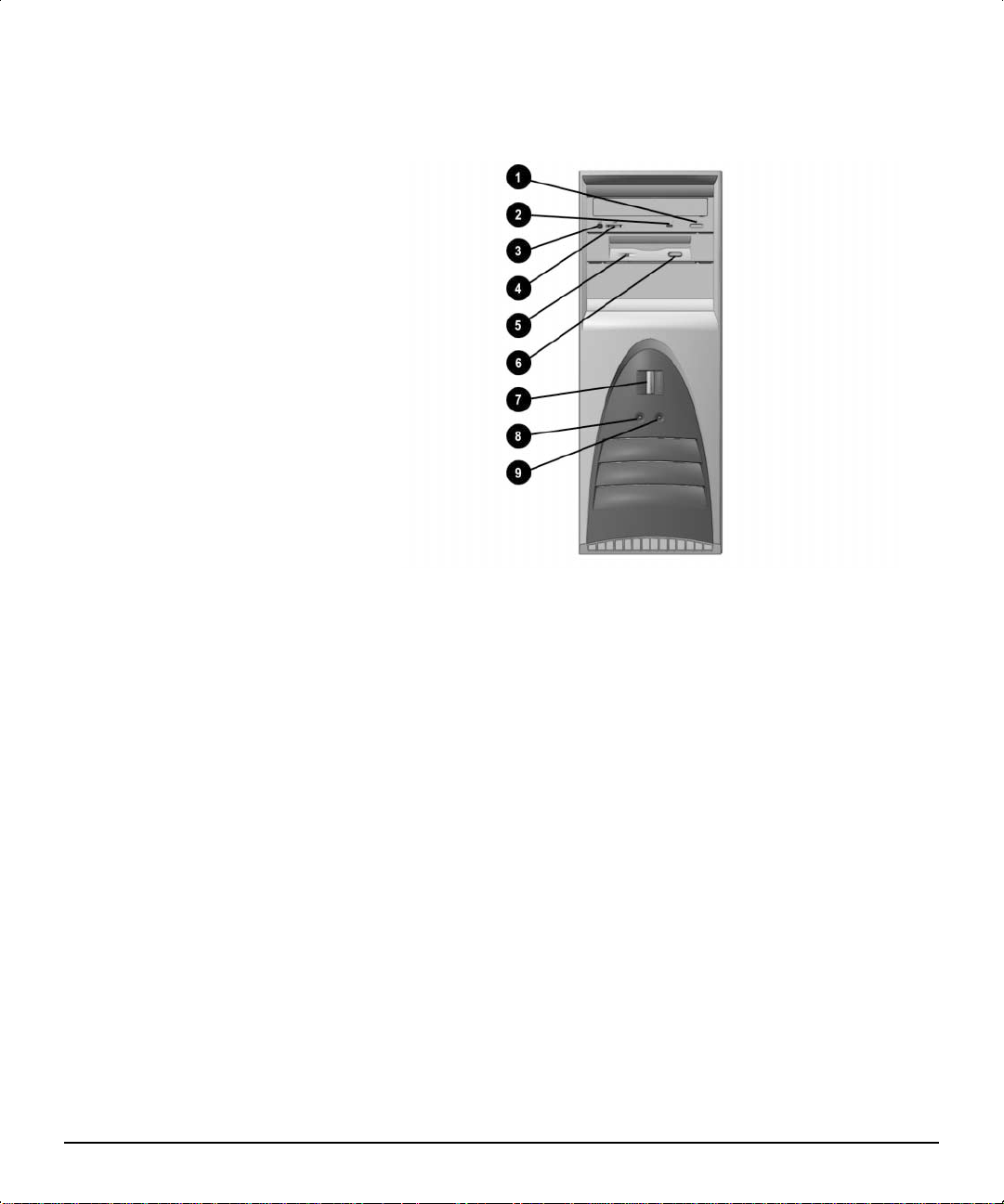
Front Panel Components
Front panel components
1 CD-ROM eject button
2 CD-ROM drive activity light
3 CD-ROM headphone jack
4 CD-ROM volume
5 Diskette drive activity light
6 Diskette eject button
7 Power button
8 Power-on light
9 Hard drive activity light
1-2 Product Features
Page 8
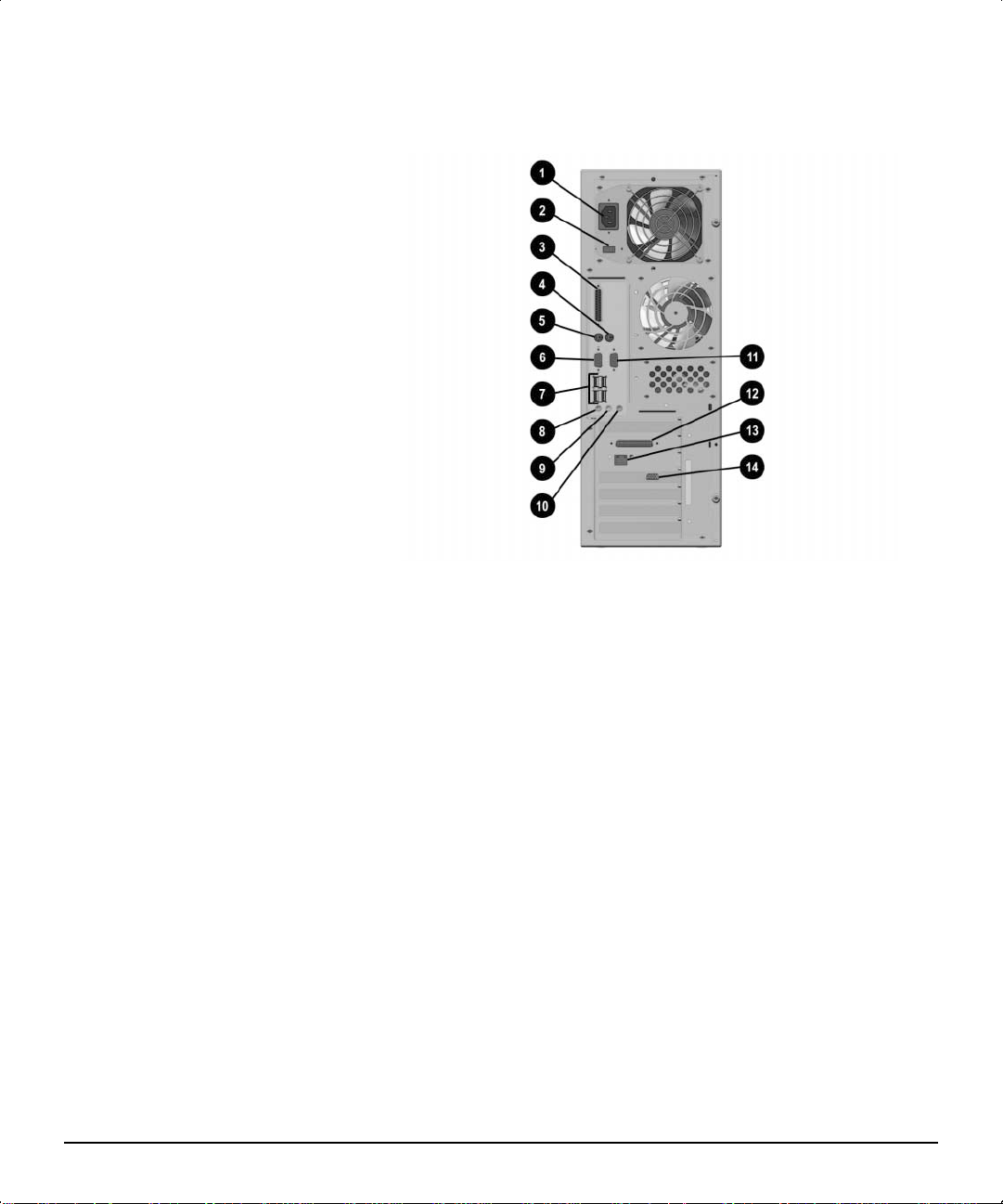
Rear Panel Components
1 Power cord connector 8 Microphone connector
2 Voltage select switch 9 Headphone/Line out connector*
3 Parallel connector : Line-in audio connector
4 Mouse connector ; Serial connector (Serial B)
5 Keyboard connector w External SCSI connector (on select models)
6 Serial connector (Serial A) e Network Interface Card (NIC) connector
7 Four universal serial bus
(USB) connectors
Rear panel components
r VGA (AGP) video connector
✎
*Your workstation has integrated audio with premium internal speaker and digital
speaker support. Digital speakers must be Sound Blaster PCI 128 compatible. An
adapter is required. Speakers and adapter are not available as a Compaq option.
Compaq Deskpro Workstation 300 Hardware Reference Guide 1-3
Page 9
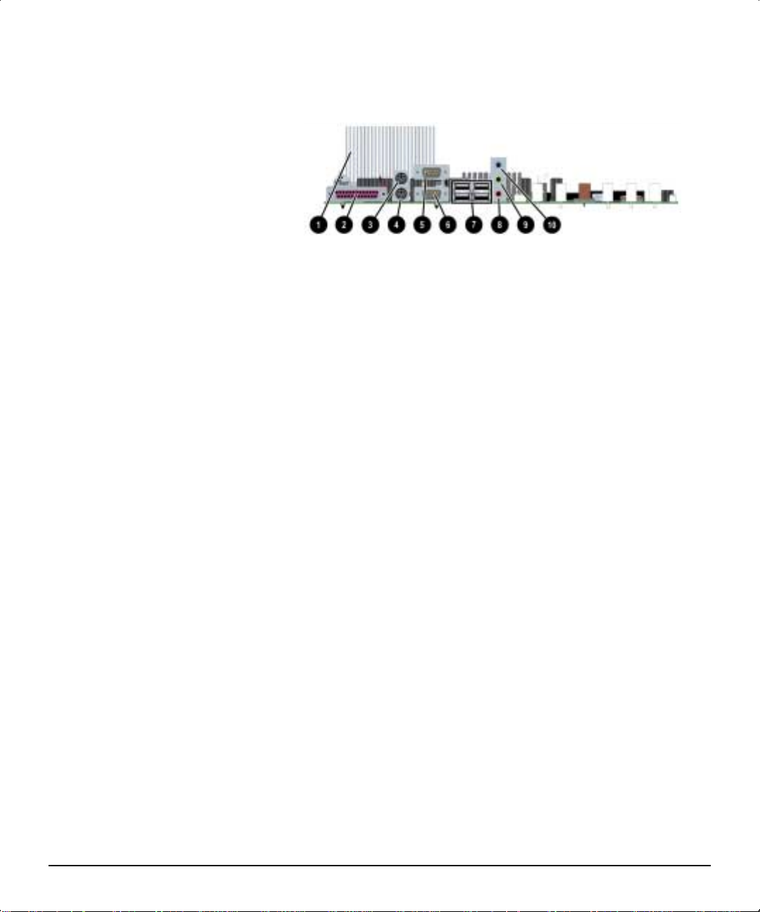
I/O Panel Components
I/O panel components
1 Heatsink
2 Parallel connector
3 Mouse connector
4 Keyboard connector
5 Serial connector (Serial B)
6 Serial connector (Serial A)
7 Four universal serial bus (USB) connectors
8 Microphone connector
9 Headphone/Line out connector*
: Line-in audio connector
1-4 Product Features
✎
*Your workstation has integrated audio with premium
internal speaker and digital speaker support. Digital
speakers must be Sound Blaster PCI 128 compatible. An
adapter is required. Speakers and adapter are not available
as a Compaq option.
Page 10
System Board Components
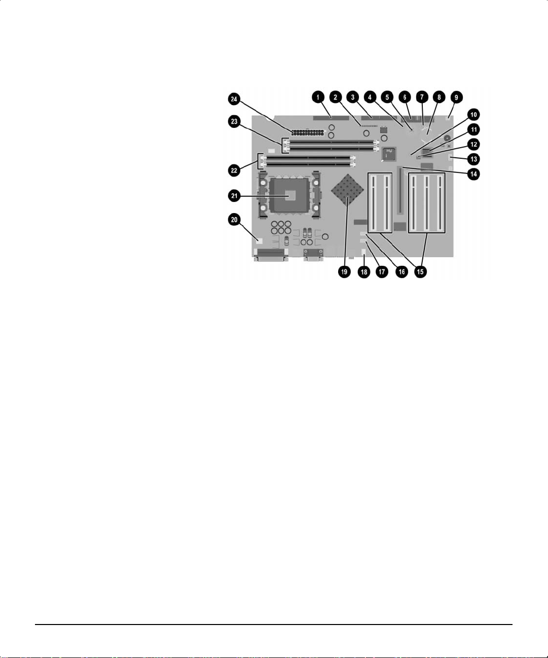
System board components
1 Secondary IDE connector = SOS connector
2 Power switch and LED connector > AGP expansion socket
3 Primary IDE connector ? Five PCI expansion sockets
4 Power button LED @ Audio auxiliary
5 CMOS reset button A CD audio connector
6 Diskette drive connector B System fan connector
7 PS-ON / 5V-AUX LED C Memory controller hub (MCH)
8 Battery D Power supply connector (P3)
9 Speaker connector E Processor
: 3.3V-AUX LED F Channel B RIMM sockets
; System ROM G Channel A RIMM sockets
< Password enabler jumper H Power supply connector
Compaq Deskpro Workstation 300 Hardware Reference Guide 1-5
Page 11
Changing from a Minitower to a Desktop Configuration
To change from a minitower to a desktop configuration:
1. Shut down the operating system properly, then turn off the
workstation and any external devices.
2. Disconnect the power cord from the grounded AC outlet then
disconnect the network cable and any external devices from the
system.
3. Remove the workstation access panel. See “Removing the
Workstation Access Panel” in Chapter 2.
4. Remove the front bezel. See to “Removing the Front Bezel” in
Chapter 2.
5. Disconnect all power and data cables from the drives in the
5.25-inch drive bay.
6. To release a drive from the 5.25-inch drive bay, slide the drivelock
as shown. Carefully push the drive from the back of the unit until
the drive casing can be grasped.
1-6 Product Features
Releasing the drives with the drivelock
CAUTION: Do not hold the face plate while removing a drive. Only
hold a drive by its casing.
Page 12
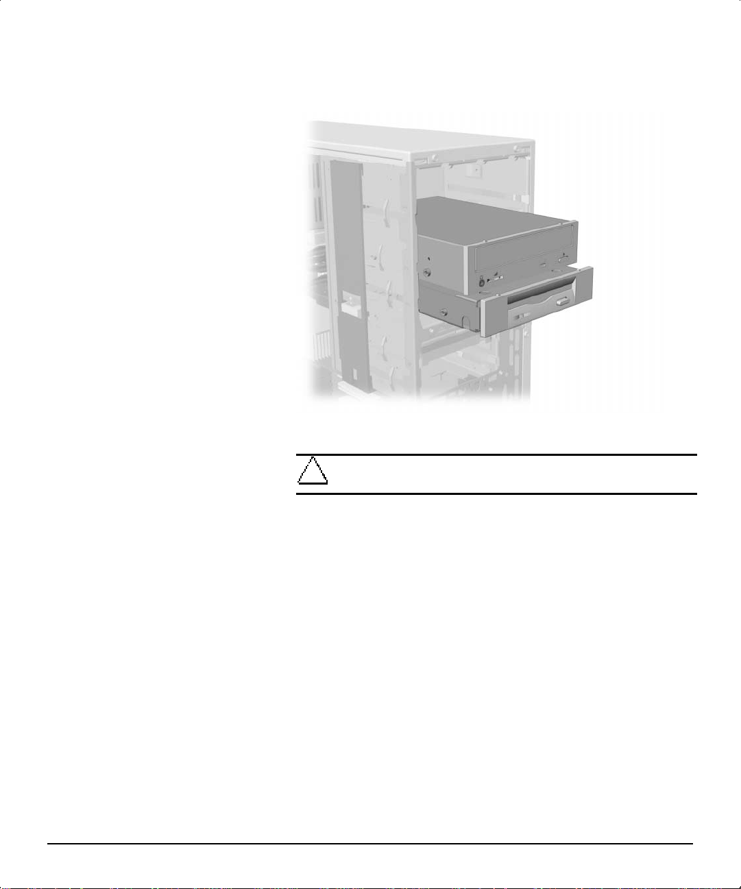
7. While holding the drive casing, gently pull the drive out of the
drive bay.
CAUTION: When removing a drive, do not pull the drive from the
front of the drive bay. To prevent damage to the drive bezel, push the
drive from the rear for removal from the front of the drive bay.
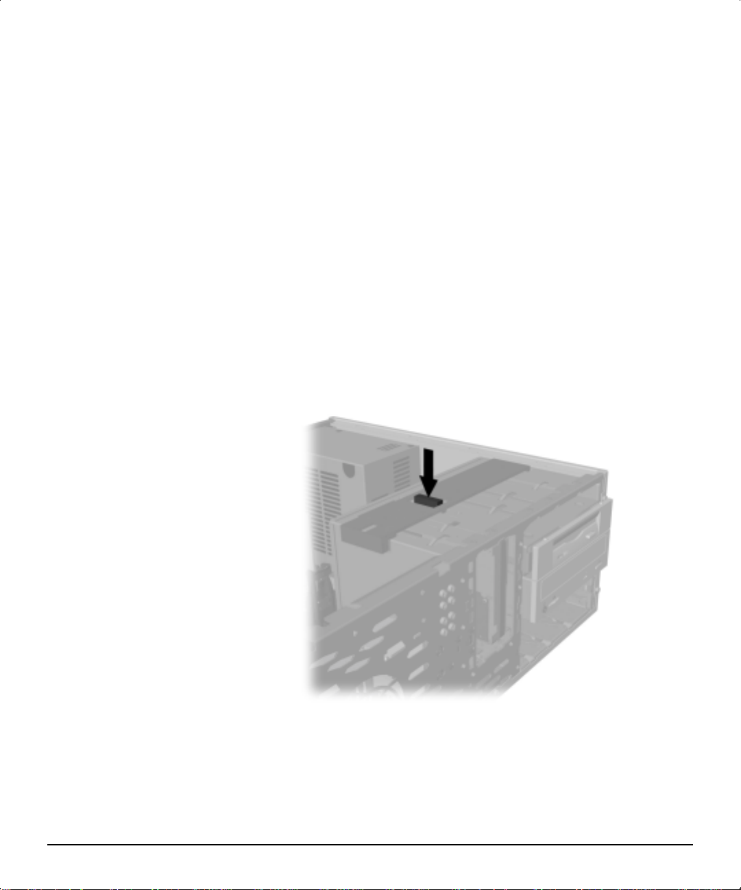
8. After placing the workstation in the desktop position, gently slide
the drives back into the bay.
Installing the drives
CAUTION: The use of unnecessary force when installing the drive
may result in damage to the drive.
✎
9. Reconnect the power and data cables to the drives as labeled.
Always place the diskette drive in the bay nearest the top of
the chassis (bay 3) in the desktop configuration to ensure
proper drive clearance and access. When all of the drives are
properly inserted, the drivelock will secure the drives in place.
Compaq Deskpro Workstation 300 Hardware Reference Guide 1-7
Page 13
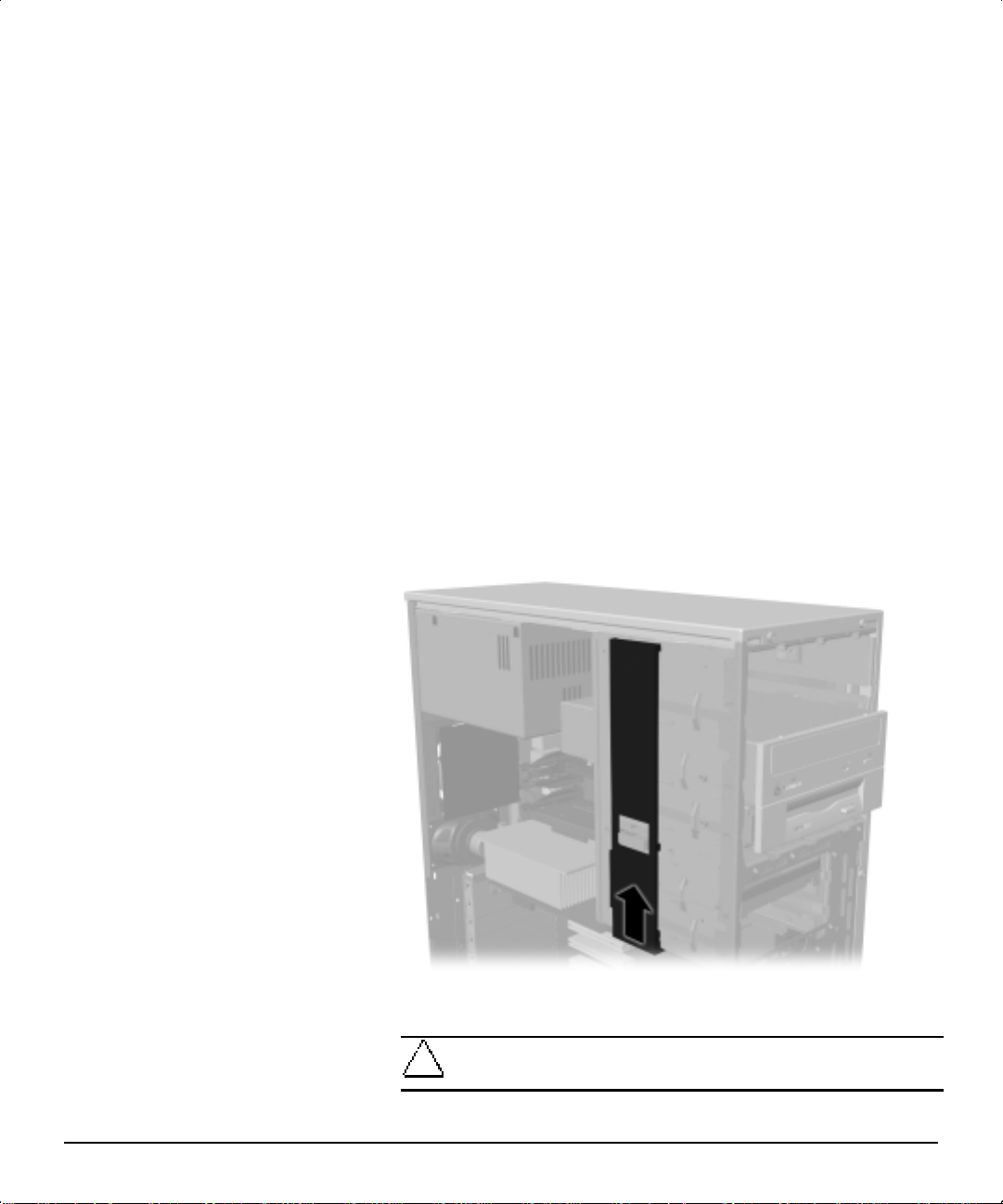
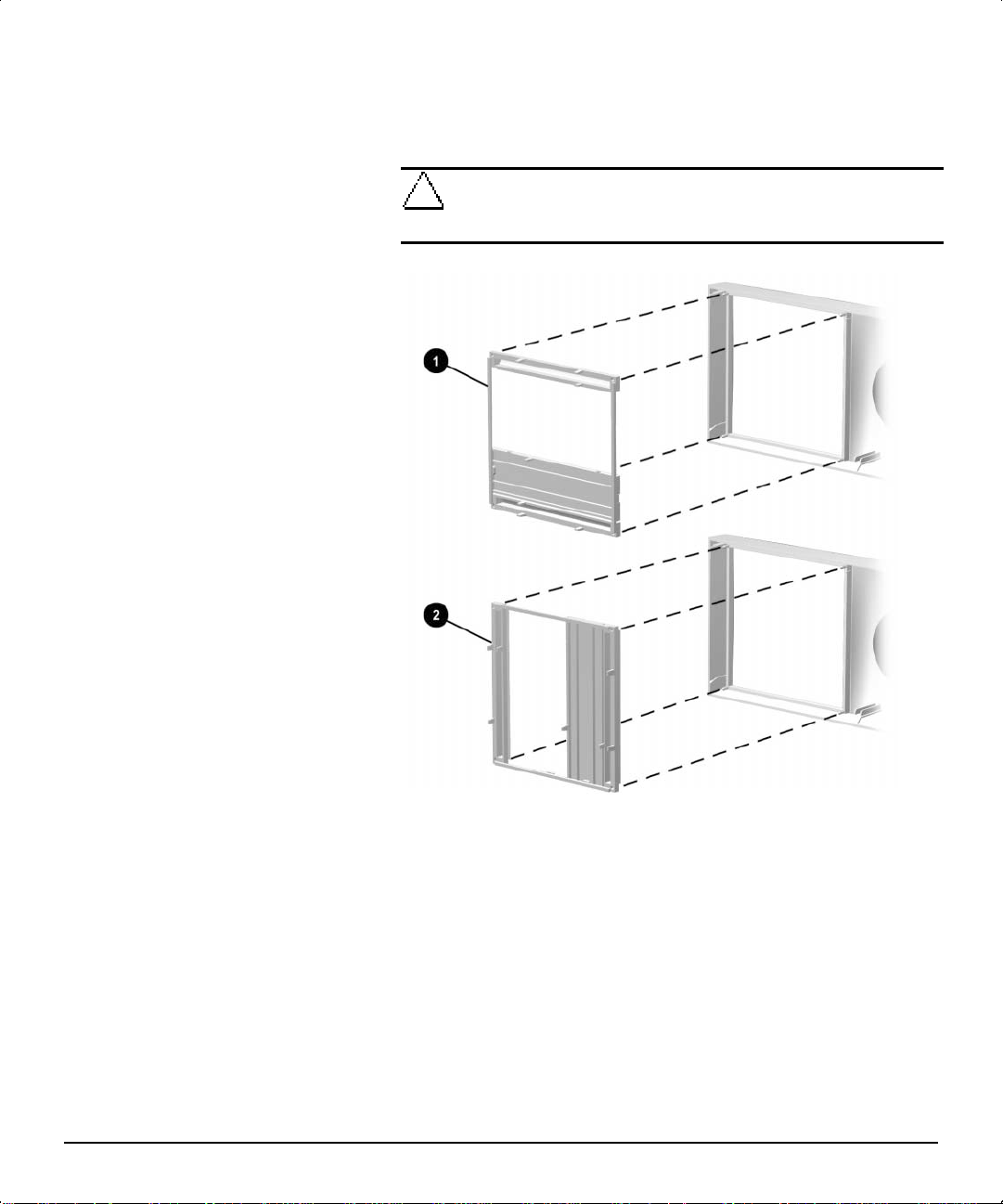
10. Remove the subpanel 1 as described in “Removing the Bezel
with the bezel
Blank” in Chapter 2, and reposition the subpanel
blank in the proper orientation for the desktop configuration.
CAUTION: Hold the subpanel straight when you pull it away from the
front bezel. Pulling the subpanel away at an angle could damage the
pins that align it within the front bezel.
2
1-8 Product Features
Changing from a minitower to a desktop configuration
✎
11. Replace the subpanel, front bezel, and the workstation access
12. Reconnect the power cord to the grounded AC outlet, then
When converting from a minitower to a desktop orientation,
use the replacement subpanel that was shipped with your
workstation to ensure that the Compaq logo is properly
oriented.
panel. Be sure that the subpanel and front bezel align properly with
the alignment tabs.
reconnect the network cable and any external devices to the
system.
Page 14
Changing from a Desktop to a Minitower Configuration
To change from a desktop to a minitower configuration:
1. Shut down the operating system properly, then turn off the
workstation and any external devices.
2. Disconnect the power cord from the grounded AC outlet then
disconnect the network cable and any external devices from the
system.
3. Remove the workstation access panel. See to “Removing the
Workstation Access Panel” in Chapter 2.
4. Remove the front bezel. See to “Removing the Front Bezel” in
Chapter 2.
5. Disconnect all power and data cables from the drives in the
5.25-inch drive bay.
6. To release a drive from the 5.25-inch drive bay, press the
drivelock as shown.
Releasing the drives with the drivelock
7. While pressing the drivelock button, push from the back of the
drives until the drive casing can be grasped.
8. While holding the drive casing, pull the drives out of the drive bay.
Compaq Deskpro Workstation 300 Hardware Reference Guide 1-9
Page 15
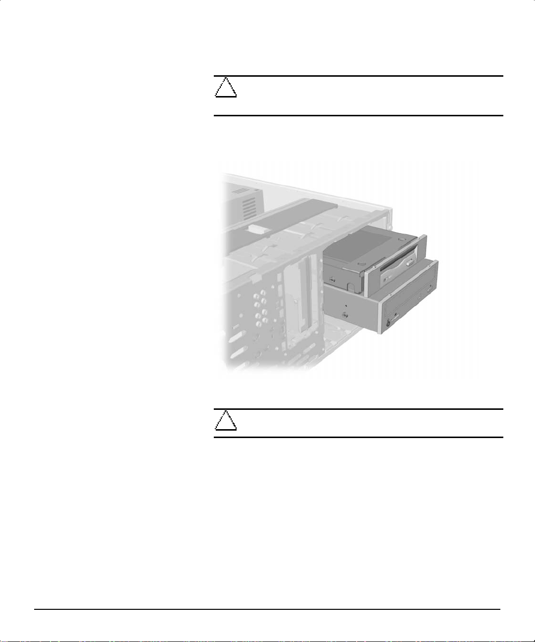
9. After placing the workstation in the minitower position, gently
slide the drives back into the bay.
Installing the drives
1-10 Product Features
CAUTION: The use of unnecessary force when installing the drives
may damage the drives.
✎
10. Reconnect the power and data cables to the drives as labeled.
Always place the 3.5-inch, high-density diskette drive in the
third bay from the top (bay 3) in the minitower configuration
for proper clearance within the chassis. When the drives are
properly inserted, the drivelock will secure them.
Page 16
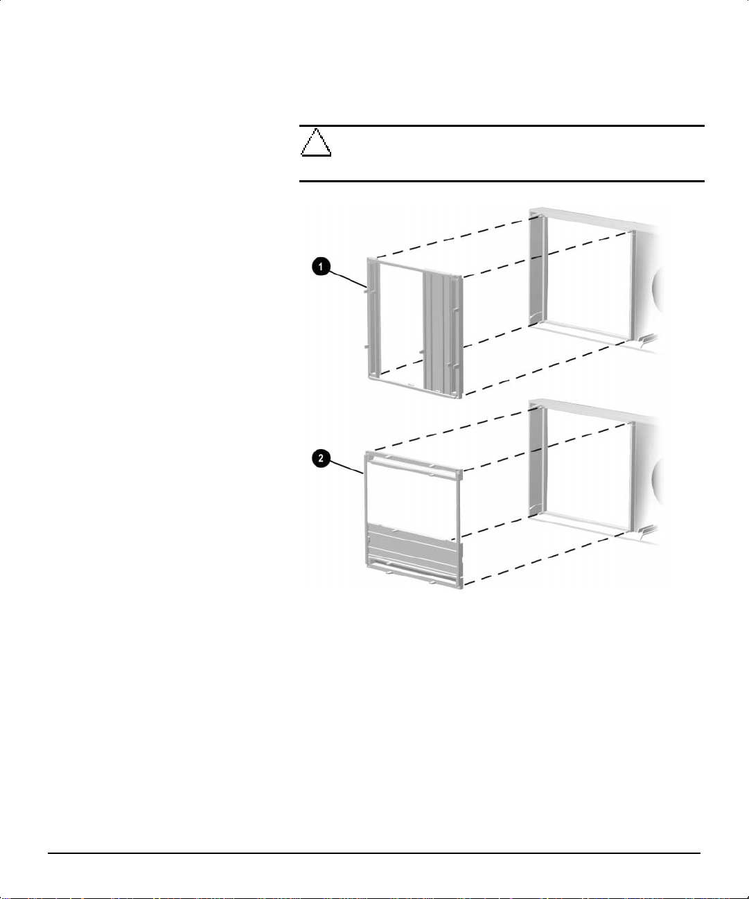
11. Remove the subpanel 1 as described in “Removing the Bezel
with the bezel
Blank” in Chapter 2, and reposition the subpanel
blank in the proper orientation for the minitower configuration.
CAUTION: Hold the subpanel straight when you pull it away from the
front bezel. Pulling the subpanel away at an angle could damage the
pins that align it within the front bezel.
2
Changing from a desktop to a minitower configuration
✎
12. Replace the subpanel, front bezel, and workstation access panel.
13. Reconnect the power cord to the grounded AC outlet, then
When converting from a desktop to a minitower orientation,
use the replacement subpanel that is shipped with your
workstation to ensure that the Compaq logo is properly
oriented.
Be sure that the subpanel and front bezel align properly with the
alignment tabs.
reconnect the network cable and any external devices to the
system.
Compaq Deskpro Workstation 300 Hardware Reference Guide 1-11
Page 17
Keyboard
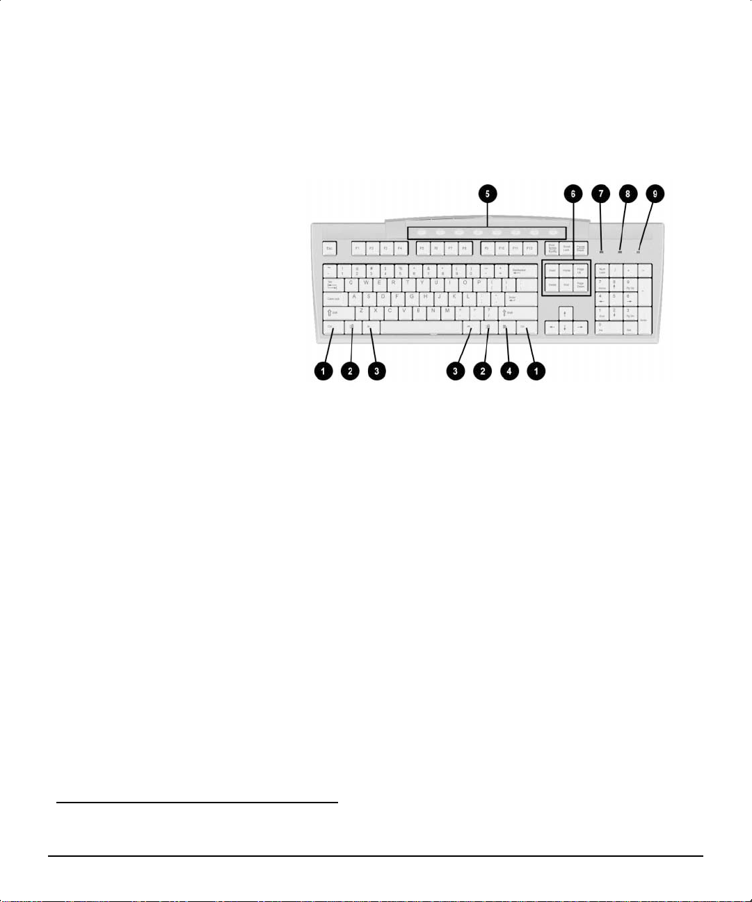
Your workstation ships with an Easy Access Keyboard. The following
figure identifies the location of keyboard lights and special function
keys.
Easy Access Keyboard components
Ref Component Function
1 Ctrl key Used in combination with another key; its effect depends on the application
software you are using.
2 Windows Logo key* Used to open the Start menu in Microsoft Windows 95. Used in combination
with other keys to perform other functions. (See “Windows Logo Key” later in
this section.)
3 Alt key Used in combination with another key; its effect depends on the application
software you are using.
4 Application key* Used (like the right mouse button) to open pop-up menus in a Microsoft
Office application. May perform other functions in other software applications.
5 Easy Access keys Provides quick and easy access to favorite Web sites, applications, and
services.
6 Editing keys Includes the following: Insert, Home, Page Up, Delete, End, and Page
Down.
NOTE: Holding down Ctrl and Alt while pressing Delete allows you to restart
your computer.
7 Num Lock light Indicates whether the Num Lock feature is on or off.
8 Caps Lock light Indicates whether the Caps Lock feature is on or off.
9 Scroll Lock light Indicates whether the Scroll Lock feature is on or off.
*Keys available in select geographic regions.
1-12 Product Features
Page 18

Easy Access Software
Your Easy Access Keyboard Buttons are programmed to default
assignments. The preinstalled Easy Access Software allows you to
reprogram the Easy Access Buttons to reflect your personal
preferences. The buttons can be reprogrammed to any program or
service of your choice or to any Web site (URL).
Reprogramming the Easy Access Buttons
The Easy Access Keyboard icon is located on the Windows desktop
Status bar. Refer to the Readme-user.txt file for instructions on
reprogramming the Easy Access Buttons.
Locking and Unlocking the Easy Access Buttons
The System Administrator can lock and unlock the Easy Access
Buttons. Once locked, the buttons can only be reprogramed by
modifying the .bcf file. For administrative privileges, which require
control of the Easy Access Button destinations, refer to the
Readme-admin.txt file.
Easy Access Paper Icon Insert
The paper icon insert functions as a visual aid in identifying the
programmed destination of each Easy Access Button. Whenever an
Easy Access Button is reprogrammed, use the Paper Insert Template
document to select and print an icon that reflects the new button
assignment. To create a new paper icon insert document, refer to the
Paper Insert Template.doc file.
✎
To properly align, the spacing around the icons may require
adjustment.
Compaq Deskpro Workstation 300 Hardware Reference Guide 1-13
Page 19

Windows Logo Key
Use the Windows Logo key in combination with other keys to perform
certain functions in Windows 2000 Professional and Windows NT
Workstation 4.0.
Special Mouse Functions
Most software applications support the use of a mouse. The functions
assigned to each mouse button depend on the software application you
are using.
Windows logo key + F1 Displays a pop-up menu for the
selected object
Windows logo key + Tab Activates the next Taskbar
button
Windows logo key + E Launches Explore My Computer
Windows logo key + F Launches Find Document
Windows logo key + Ctrl + F Launches Find Computer
Windows logo key + M Minimizes all open applications
Shift + Windows logo key + M Undoes Minimize All
Windows logo key + R Displays Run dialog box
Serial Number Location
1-14 Product Features
Each computer has a unique serial number located on the corner of the
computer access panel and on the rear panel of the computer. Keep this
number available when contacting Compaq customer service.
Page 20

chapter
2
ARDWARE UPGRADES
H
This chapter explains how to remove the workstation access panel and
the front bezel. It also explains how to install the following hardware:
■ Memory
■ Drives
■ Expansion boards
✎
Compaq recommends that you finish the setup procedures for
the preinstalled software before you install any optional
hardware or third-party devices that were not included with
your workstation.
Compaq Deskpro Workstation 300 Hardware Reference Guide 2-1
Page 21

Installation Sequence
Follow this sequence of steps to ensure the proper installation of any
optional equipment. Before you begin, observe the following
precautions:
WARNING: To reduce the risk of personal injury from hot surfaces,
!
allow the internal system components to cool before touching them.
WARNING: To reduce the risk of electrical shock, fire, or damage to
!
the equipment, do not plug telecommunications/telephone connectors
into the network interface controller (NIC) receptacles.
CAUTION: Static electricity can damage the electronic components
of the workstation or optional equipment. Before beginning these
procedures, ensure that you are discharged of static electricity by
briefly touching a grounded metal object.
1. Turn off the workstation and disconnect the power cord from the
grounded AC outlet.
2. Disconnect the keyboard, monitor, network cable, and other
external equipment connected to the workstation.
3. Open the workstation by removing its workstation access panel.
See “Removing the Workstation Access Panel” in this chapter for
instructions.
2-2 Hardware Upgrades
4. If you are installing or removing drives in the front bays, see
“Removing the Front Bezel” in this chapter for instructions.
5. Install any optional equipment, such as memory, additional drives,
expansion boards, processors, or batteries. See the appropriate
sections in this chapter or the appendixes for installation
instructions. Also refer to the documentation provided with the
optional equipment.
6. Replace the front bezel and the workstation access panel, if
necessary.
7. Reconnect the keyboard, monitor, network cable, and other
external devices.
8. Plug the power cord into a grounded AC outlet.
9. Turn on the monitor, workstation, and any external devices you
installed.
10. Reconfigure the workstation, if necessary.
11. Test the workstation (optional) using the TEST utility.
Page 22

Removing the Workstation Access Panel
To remove the workstation access panel:
1. Shut down the operating system properly, then turn off the
workstation and any external devices.
2. Disconnect the power cord from the grounded AC outlet.
3. To remove the workstation access panel, loosen the two
thumbscrews as shown in the following illustration.
Loosening the two thumbscrews and removing the workstation access panel
✎
When replacing the workstation access panel, be sure to
tighten both thumbscrews.
Compaq Deskpro Workstation 300 Hardware Reference Guide 2-3
Page 23

Removing the Front Bezel
To remove the front bezel:
1. Shut down the operating system properly, then turn off the
2. Disconnect the power cord from the grounded AC outlet.
3. Remove the workstation access panel. See “Removing the
workstation and any external devices.
Workstation Access Panel” in this chapter.
4. Push in on the two front bezel release tabs
away from the chassis to release it.
2
bezel
Pressing the two front bezel release tabs to remove the front bezel
, then rotate the front
1
2-4 Hardware Upgrades
✎
When replacing the front bezel, ensure that the bottom hinge
points are properly placed in the chassis before rotating the
front bezel back into its original position.
Page 24

Installing Additional Memory
The Compaq Deskpro Workstation 300 supports Error Checking and
Correcting (ECC) Direct Rambus inline memory modules (RIMMs).
Additional RIMMs are available to upgrade the memory. A maximum
of 32 count Direct RDRAM devices is supported on each Direct
Rambus memory channel. Continuity RIMMs (CRIMMs) must
populate any empty sockets.
Installing and Removing RIMMs
RIMM Socket Locations
Your workstation supports a total of four RIMM sockets on two Direct
RDRAM channels. A maximum of 32 Direct RDRAM devices is
supported per channel.
The four RIMM sockets are numbered XMM1 and XMM2
(Channel A) and XMM3 and XMM4 (Channel B).
Location of RIMM sockets
1 RIMM Socket XMM3, Channel B
2 RIMM Socket XMM4, Channel B
3 RIMM Socket XMM1, Channel A
4 RIMM Socket XMM2, Channel A
Compaq Deskpro Workstation 300 Hardware Reference Guide 2-5
Page 25

Guidelines for RIMM Installation
Follow the guidelines listed below when installing RIMMs:
■ RIMMs must be installed correctly. Be sure to match the two key
sockets on the RIMM with the tabs on the RIMM socket. Push the
RIMM down into the RIMM socket, ensuring that it is fully
inserted and properly seated and that the retaining arms are locked
in place.
■ CRIMMs must be installed in all empty RIMM sockets. Remove
the CRIMMs when you want to populate the sockets with RIMMs.
For examples of the correct configuration sequence, see “Installing
RIMMs” in this chapter.
■ Install RIMMs in pairs across both memory channels. Each RIMM
socket populated with a RIMM or CRIMM on Channel A must be
populated with an identical RIMM or CRIMM on Channel B. For
examples of the correct configuration sequence, see “Installing
RIMMS” in this chapter.
■ Do not exceed 32-count Direct RDRAM devices on each Direct
Rambus memory channel. A label on the RIMM will indicate the
number and speed of Direct RDRAM devices on the RIMM.
✎
■ Do not mix RIMMs with different memory speeds. Performance
You cannot remove or add Direct RDRAMs to a RIMM
because the Direct RDRAMs are soldered on and encased by
another material.
will reflect the slowest speed RIMM.
CAUTION: Static electricity can damage the electronic components
of the workstation or optional boards. Before beginning these
procedures, ensure that you are discharged of static electricity by
briefly touching a grounded metal object.
CAUTION: Your workstation will not function if the above guidelines
are not followed when installing RIMMs.
CAUTION: When handling a memory module, do not touch any of the
contacts. Doing so can damage the module.
2-6 Hardware Upgrades
Page 26

Installing RIMMs
When installing RIMMs, you must use the configurations in the
following table.
RIMM Installation Configurations
Memory
Channel A
RIMM
Possible
Configuration
1 RIMM CRIMM RIMM CRIMM
2 RIMM RIMM RIMM RIMM
WARNING: To reduce the risk of personal injury when replacing or
!
removing RIMMs, allow the module being removed from the RIMM
socket sufficient time to cool. RIMM temperatures can reach 212°F
(100°C).
CAUTION: When handling a RIMM, do not touch any of the contacts.
Doing so may damage the module.
CAUTION: Static electricity can damage the electronic components
of the workstation or option boards. Before beginning these
procedures, ensure that you are discharged of static electricity by
briefly touching a grounded metal object.
Before installing additional RIMMs, read “Guidelines for RIMM
Installation” in this chapter.
Socket
XMM1
RIMM
Socket
XMM2
Memory
Channel B
RIMM
Socket
XMM3
RIMM
Socket
XMM4
✎
CRIMMs must be installed in all unpopulated RIMM sockets.
Compaq Deskpro Workstation 300 Hardware Reference Guide 2-7
Page 27

To install a memory module:
1. Turn off the workstation and any external devices, then disconnect
the power cord from the grounded AC outlet.
On a power-managed system, the power cord must be
disconnected from the grounded AC outlet.
2. Remove the workstation access panel and locate the RIMM
sockets.
CAUTION: Be sure to follow the correct configuration guidelines to
your respective memory board, or your system will not function.
3. Refer to the following illustration to install a RIMM module.
Removing RIMMs
2-8 Hardware Upgrades
Installing a RIMM module
4. Reassemble the workstation.
To remove a memory module from a RIMM socket, reverse the
procedures in the previous section.
Page 28

Installing Additional Drives
This section provides a description of the drive bay components. It alos
provides instructions for removing a bezel blank and how to install or
remove a drive.
Drive Bay Components
Your workstation supports up to five drive bays. Drive bays
through 3 are located on the front of the workstation. Bays 4 and
are located inside the workstation. The drives support various drive
configurations.
✎
Drive bay numbers are stamped on the chassis, behind the
front bezel.
Minitower Drive Bay Positions
1
5
Identifying minitower drive bay components
1 Bay 1—5.25-inch, half-height bay for optional drive
2 Bay 2—5.25-inch, half-height bay for optional drive
3 Bay 3—3.5-inch, high-density diskette drive mounted in the
5.25-inch, one-third height bay
4 Bay 4—3.5-inch, one-third height bay for hard drive
5 Bay 5—3.5-inch, one-third height bay for hard drive
Compaq Deskpro Workstation 300 Hardware Reference Guide 2-9
Page 29

Desktop Drive Bay Positions
Identifying desktop drive bay components
1 Bay 5—3.5-inch, one-third height bay for hard drive
2 Bay 4—3.5-inch, one-third height bay for hard drive
3 Bay 3—3.5-inch, high-density diskette drive mounted in the
5.25-inch, one-third height bay
4 Bay 1—5.25-inch, half-height bay for optional drive
5 Bay 2—5.25-inch, half-height bay for optional drive
2-10 Hardware Upgrades
Page 30

Preparing for Drive Installation
Remove the drive bezel blank before installing any removable media
storage device, such as a tape drive, CD-ROM or DVD-ROM drive, or
diskette drive, in these bay locations.
Removing the Bezel Blank
To remove the bezel blank:
1. Shut down the operating system properly, then turn off the
workstation and any external devices.
2. Disconnect the power cord from the grounded AC outlet.
3. Remove the workstation access panel. See “Removing the
Workstation Access Panel” in this chapter.
4. Remove the front bezel. See “Removing the Front Bezel” in this
chapter.
5. Gently pull the subpanel, with the bezel blank still secured, away
from the front bezel. Remove the bezel blank from the subpanel.
CAUTION: Hold the subpanel straight when you pull it away from the
front bezel. Pulling the subpanel away at an angle could damage the
pins that align it within the front bezel.
Removing the bezel blank from the subpanel
Compaq Deskpro Workstation 300 Hardware Reference Guide 2-11
Page 31

Installing a Drive
Installing a Hard Drive into a 3.5-inch Drive Bay
✎
The following sections provide instructions for installing a hard drive
in a 3.5-inch drive bay and in a 5.25-inch drive bay.
When replacing the subpanel, ensure that the aligning pins are
properly oriented.
When converting from a minitower to a desktop orientation,
use the replacement subpanel that is shipped with your
workstation to ensure that the Compaq logo is properly
oriented.
✎
To install a hard drive in a 3.5-inch drive bay:
1. Turn off the workstation and disconnect the power cord from the
2. Remove the Workstation access panel. See “Removing the
3. Remove the front bezel. See “Removing the Front Bezel” in this
Compaq does not support mixing Ultra ATA and SCSI hard
drives in the same system. If you are replacing a hard drive in
bay 4 or bay 5, the replacement drive should be of the same
type as the drive being removed.
grounded AC outlet.
Workstation Access Panel” in this chapter.
chapter.
2-12 Hardware Upgrades
Page 32

4. To install a hard drive into a 3.5-inch bay, see the following two
illustrations.
Installing a hard drive into a 3.5-inch hard drive bay
Compaq Deskpro Workstation 300 Hardware Reference Guide 2-13
Page 33

Connecting the signal cable and power cable
5. Connect the opposite end of the cables to the appropriate system
board connectors. To locate the appropriate drive connectors, see
“System Board Components” in Chapter 1.
6. Reassemble the workstation.
2-14 Hardware Upgrades
Page 34

Installing a Hard Drive into a 5.25-Inch Drive Bay
To install a 3.5-inch hard drive into a half-height, 5.25-inch drive bay,
the drive must be housed in an adapter. To install the drive and adapter:
1. Turn off the workstation and any external drives. Disconnect the
power cord from the grounded AC outlet. Then remove the
workstation access panel. See “Removing the Workstation Access
Panel” in this chapter.
2. Remove the front bezel. See “Removing the Front Bezel” in this
chapter.
3. To secure the drive to the adapter install the four screws into the
drive as shown in the following illustration.
4. Install the guide screws into the hard drive adapter.
5. Install the adapter in the drive bay by sliding it into the front of the
drive cage. The drivelock automatically secures the adapter when
the drivelock snaps into place.
Aligning the guide screws and installing a 3.5-inch drive
Compaq Deskpro Workstation 300 Hardware Reference Guide 2-15
Page 35

Removing a Drive
Connecting the signal and power cables
6. Connect the opposite end of the cables to the appropriate system
board connectors. To locate the appropriate drive connectors, see
“System Board Components” in Chapter 1.
7. Reassemble the workstation.
2-16 Hardware Upgrades
✎
1. Shut down the operating system properly, then turn off the
2. Remove the workstation access panel. See “Removing the
3. Remove the front bezel. See “Removing the Front Bezel” in this
4. Disconnect the drive power and signal cables and, if it is a
Compaq does not support mixing Ultra ATA and SCSI hard
drives in the same system. If you are replacing a hard drive in
bay 4 or bay 5, the replacement drive should be of the same
type as the drive being removed.
workstation and any external devices.
Workstation Access Panel” in this chapter.
chapter.
CD-ROM drive, disconnect the audio connector.
Page 36

5. Release the drivelock.
❏ If the drive is in the minitower position, slide the drivelock to
unlock the drive in the drive bay.
Releasing the drives with the drivelock
Compaq Deskpro Workstation 300 Hardware Reference Guide 2-17
Page 37

❏ If the drive is in the desktop position, press the drivelock
button to unlock the drive.
Releasing the drives with the drivelock button
6. While releasing the drivelock, push from the back of the drives
until the drive casing can be grasped from the front of the
workstation.
2-18 Hardware Upgrades
7. While holding the drive casing, pull the drives out of the drive bay.
8. Store the drives in antistatic packaging.
9. Reassemble the workstation.
Page 38
Installing and Removing an Expansion Board
This section provides instructions for installing and removing PCI and
AGP expansion boards.
✎
For product documentation related to your graphics controller,
refer to the Workstation Reference Library CD included with
your workstation.
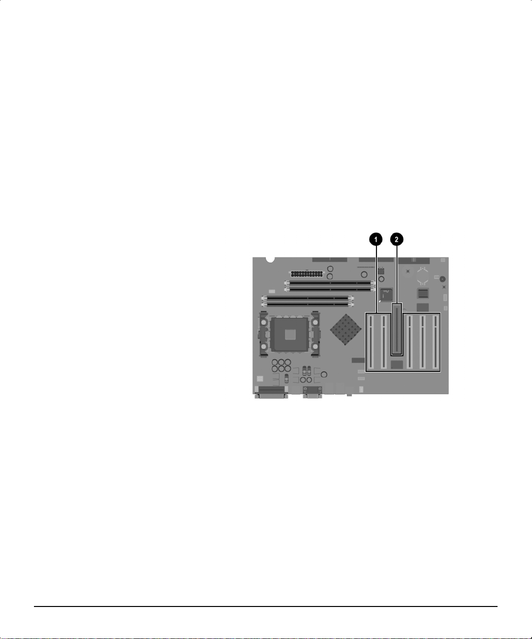
Identifying the PCI and AGP Expansion Sockets
This workstation contains five PCI sockets and one AGP socket. The
following illustration identifies the physical locations of these sockets.
Identifying PCI and AGP expansion sockets
1
Five PCI expansion sockets
2
One AGP expansion socket
Compaq Deskpro Workstation 300 Hardware Reference Guide 2-19
Page 39

Installing an Expansion Board
To install an expansion board:
1. Turn off the workstation and disconnect the power cord from the
grounded AC outlet.
2. Remove the workstation access panel and locate the correct vacant
slot in the workstation chassis.
3. Remove the screw securing the expansion slot cover, then remove
the slot cover, as illustrated.
2-20 Hardware Upgrades
Removing the screw and expansion slot cover
Page 40

4. Slide the expansion board into the expansion socket and press the
board firmly into place.
When installing an expansion board, press firmly on the board so
that the whole connector seats properly in the expansion board
socket.
✎
If installing an AGP expansion board, the board must have an
ATX bracket.
Installing an expansion board
5. Replace the screw to secure the board in the expansion socket.
6. Reassemble the workstation.
Removing an Expansion Board
To remove an expansion board, reverse the steps in the previous
section. When reversing these steps:
■ Be sure to store the board in antistatic packaging.
■ Install an expansion slot cover to close the open slot.
Compaq Deskpro Workstation 300 Hardware Reference Guide 2-21
Page 41

appendix
A
PECIFICATIONS
S
Compaq Deskpro Workstation 300
Component U.S. Metric
Minitower Dimensions
Height
Width
Depth
Desktop Dimensions
Height
Width
Depth
Approximate Weight 26 lb 12 kg
Power Supply
Operating Voltage Range
Rated Voltage Range
Rated Line Frequency
Temperature
Operating
Shipping
Humidity (noncondensing)
Operating
Nonoperating
Maximum Altitude (unpressurized)
Operating
Nonoperating
Power Output 265 W 265 W
Rated Input Current (maximum)
200 W 7.5 A 3.75 A
Heat Dissipation (maximum)
Maximum
Nominal
17.65 in.
6.60 in.
17.11 in.
6.60 in.
17.65 in.
17.11 in.
90-132 VAC
100-127 VAC
50-60 Hz
50° to 95°F
-4° to 140°F
20% to 80%
10% to 90%
10,000 ft
30,000 ft
1390 Btu/hr
690 Btu/hr
44.83 cm
16.76 cm
43.46 cm
16.76 cm
44.83 cm
43.46 cm
180-264 VAC
200-240 VAC
50-60 Hz
10° to 35°C
-20° to 60°C
3,048 m
9,144 m
350 kg-cal/hr
175 kg-cal/hr
Deskpro Workstation 300 Hardware Reference Guide A-1
Page 42

appendix
B
ARD DRIVE INSTALLATION
H
Using the Cable-Select Feature with Ultra ATA Devices
Select models of the Compaq Deskpro Workstation 300 have an
internal IDE Ultra ATA hard drive preinstalled. The configuration of
the drives employs a cable-select feature that identifies the drives as
device 0 (primary drive) or device 1 (secondary drive).
The system board determines which drive is device 0 or device 1,
based on the way the drives are connected to the special drive cable.
The device 0 drive is the drive connected to the short segment of the
drive cable (or the connector closest to the system board); the device 1
drive is the drive connected to the long segment of the drive cable.
Compaq hard drives ship with jumpers preset to cable-select mode;
therefore, no jumper setting changes on the existing or optional drives
are required. If you purchase a third-party hard drive, refer to the
documentation included with the kit to ensure proper installation and
configuration of cables.
✎
If installing a second device on the primary controller,
you must use an 80 conductor Ultra ATA cable for
optimal performance. This cable is standard on select
models.
Compaq Deskpro Workstation 300 Hardware Reference Guide B-1
Page 43

Guidelines for Installing Ultra ATA IDE Devices
When installing additional IDE drives, follow these guidelines:
■ For optimal performance, connect hard drives to the primary
controller. Connect expansion devices, such as IDE CD-ROM
drives, tape drives, and diskette drives, to the secondary controller.
■ Install either a third-height or a half-height drive into a half-height
bay.
■ Install guide screws to ensure that the drive lines up correctly in
the drive cage. Compaq has provided extra guide screws, which
are installed in the front of the workstation chassis behind the front
bezel. Some options use M3 metric hardware. Compaq-supplied
metric screws are black.
SCSI Devices
This section contains information relating to SCSI device guidelines
and installation.
Guidelines for Using SCSI Devices
When installing and operating SCSI devices, you must follow these
guidelines:
B-2 Hard Drive Installation
■ A single Ultra SCSI, Ultra-Wide SCSI, Wide Ultra2 SCSI, or
Wide-Ultra160 SCSI controller allows you to daisy-chain up to
15 additional SCSI devices. Including the controller, that equals
16 total SCSI devices.
■ If 2 SCSI controllers are present, each connected to separate
system board SCSI connector, each controller may have 7 SCSI
devices attached. This configuration yields a total of 16 SCSI
devices on the system.
Page 44

■ Each SCSI controller requires a unique SCSI ID (0-7 or 8-15) for
each SCSI device installed. The controller identifies a SCSI device
by its SCSI ID number rather than by its location. Moving a SCSI
device from one position to another on the SCSI chain does not
affect communication between the controller and the device. The
reserved and available SCSI ID numbers for SCSI devices are the
following:
❏ 0–reserved for the primary hard drive
❏ 7–reserved for the controller
❏ 1 through 6 and 8 through 15 – available for all other SCSI
devices
■ If only one SCSI hard drive is used, it should be installed in the
lowest numbered bay (bay 1).
■ Every SCSI chain or circuit must be terminated (closed) at both
ends. Some system boards have both ends of the SCSI cable
connected to, and terminated by, the system board. Termination
can be accomplished through one of the following methods:
❏ Using a cable with a built-in terminator.
❏ Using a cable with a terminating resistor plug in the last
connector.
❏ Connecting a SCSI device with its termination enabled into
the last connector.
❏ Connecting an external SCSI device with its termination
enabled to the external SCSI connector on the rear panel of
the computer.
Compaq Deskpro Workstation 300 Hardware Reference Guide B-3
Page 45

■ Turn on all external SCSI devices before turning on the power to
the computer. This enables the SCSI controller to recognize the
external devices.
■ All SCSI hard drives must be either internal or external, but never
both. The system accommodates a combination of other internal
and external SCSI devices, such as tape and CD-ROM drives.
■ Compaq does not recommend mixing different width SCSI devices
on the same SCSI chain or on the same SCSI controller. Mixing
devices of different widths on the same chain or controller will
always result in a data transfer rate of the slowest machine in that
chain. It is acceptable to mix Wide-Ultra2 and Wide-Ultra160
SCSI devices, but do not mix Narrow devices with any devices
other than Narrow devices.
For additional information about optional SCSI devices, refer to the
documentation included with the device or contact your Compaq
authorized dealer, reseller, or service provider.
CAUTION: Do not route cables near the air intake to the power supply.
Cables routed in this manner can block airflow to the power supply, causing
it to overheat.
B-4 Hard Drive Installation
Page 46

Guidelines for Installing SCSI Devices
SCSI Cables
Compaq does not support mixing Ultra ATA and SCSI hard drives in
the same system.
On a Compaq Deskpro Workstation 300 for which you are replacing a
hard drive in bay 4 or 5, the replacement drive should be the same type
as the drive being removed. If you are replacing the Ultra ATA hard
drive with a SCSI hard drive, you will need a SCSI device option kit
and the SCSI controller option kit. The controller option kit contains
the SCSI controller and a cable that supports multiple SCSI devices.
Before installing a SCSI device on any workstation:
■ Verify the SCSI ID of the drive and, if necessary, set the SCSI ID
to a unique number. See “Guidelines for Using SCSI Devices” in
this appendix or refer to the documentation included with the
device.
■ Determine if the device requires termination to be enabled or
disabled. Set the termination if necessary. See “Using a SCSI
Cable” in this appendix or refer to the documentation included
with the device.
Using a SCSI Cable
You can install mass storage SCSI devices in the front drive bays of
your workstation.
Select models of the Compaq Deskpro Workstation 300 ship with a
multimode SCSI cable that supports LVD or single-ended devices.
(UATA models do not ship with a SCSI cable). The cable
accommodates up to three SCSI devices in the front drive bay area.
Some Compaq Deskpro Workstation 300 models ship with an internal
SCSI drive preinstalled in the front drive bay area. You can add
additional high-performance SCSI drives using the external SCSI
connector located on the rear panel of the workstation.
Five-device SCSI cable with terminator
Compaq Deskpro Workstation 300 Hardware Reference Guide B-5
Page 47

The cable that shipped with your workstation may look different than
the one illustrated (a five-device cable).
✎
If you are installing a narrow SCSI device, you will need
to attach a 68-pin to 50-pin SCSI adapter.
For additional information about installing optional SCSI devices, refer
to the documentation included with the device option kit, or contact
your Compaq authorized dealer, reseller, or service provider.
Using SCSISelect with SCSI Devices
The Wide-Ultra160 SCSI host adapter includes the SCSISelect utility
to configure the host adapter and to run SCSI disk utilities. To run the
SCSISelect utility:
■ In POST Messages Enabled mode: Press Ctrl+A when the Press
<Ctrl><A> for SCSISelect Utility message appears during POST.
■ In POST Messages Disabled mode: When the Compaq logo screen
appears, press any key to exit the logo screen. Immediately after
exiting the logo screen, press Ctrl+A to access the SCSISelect
utility.
A menu appears with the following options:
■ Configure/View Host Adapter Settings
❏ SCSI Bus Interface Definitions
B-6 Hard Drive Installation
–
Host Adapter SCSI ID
–
SCSI Parity Checking
–
Host Adapter SCSI Termination
❏ Additional Options
–
Boot Device Options
–
SCSI Device Configuration
–
Advanced Configuration Options
■ SCSI Disk Utilities
Lists all SCSI devices and SCSI ID numbers
✎
For information about configuring POST message
display status, refer to the
Computer Setup
guide.
Page 48

appendix
ATTERY REPLACEMENT
B
Procedure for Replacing the Battery
The battery that comes with your computer provides power to the realtime clock and has a lifetime of about three years. When replacing the
battery, use an equivalent 3-volt lithium coin cell battery.
WARNING: Your computer contains an internal lithium manganese
dioxide, vanadium pentoxide, or alkaline battery or battery pack. There
is a risk of fire and burns if the battery pack is not handled properly.
To reduce the risk of personal injury:
Do not attempt to recharge the battery.
Do not expose to temperatures higher than 60°C (140ºF).
Do not disassemble, crush, puncture, short external contacts, or
dispose of in fire or water.
Replace only with the Compaq spare designated for this product.
Batteries, battery packs, and accumulators should not be disposed of
together with the general household waste. To forward them to
recycling or proper disposal, please use the public collection system
or return them to Compaq, your authorized partners, or their agents.
C
Compaq Deskpro Workstation 300 Hardware Reference Guide C-1
Page 49

To replace the battery:
1. Shut down the operating system properly, turn off the computer
and any external devices, disconnect the power cord from the
electrical outlet, and remove the computer cover or access panel.
✎
It may be necessary to remove an expansion card to gain
access to the battery.
2. Locate the battery and battery holder on the system board, as
shown in the following illustration.
C-2 Battery Replacement
Battery and Battery Holder
Page 50
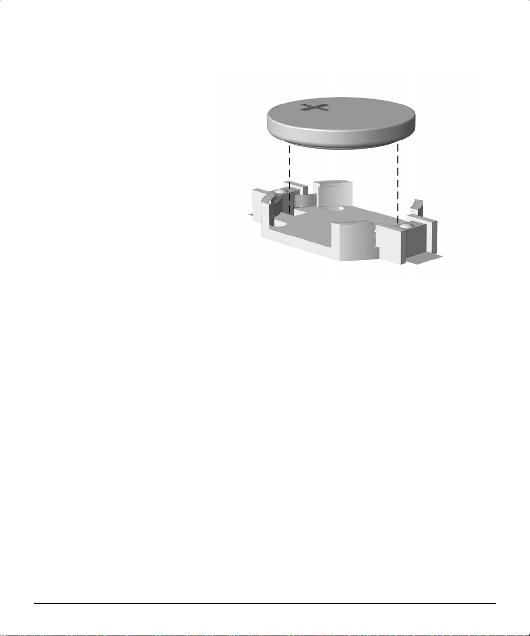
3. Lift the battery out of its holder.
Removing the Coin Cell Battery
4. Slide the replacement battery into position, positive side up. The
battery holder automatically secures the battery in the proper
position.
5. Replace any expansion boards you removed.
6. Replace the computer cover or access panel.
7. Plug in the computer and turn on power to the computer.
8. Reset the date and time, your passwords, and any special system
setups, using Compaq Computer Setup. Refer to the Computer
Setup guide for additional information.
Compaq Deskpro Workstation 300 Hardware Reference Guide C-3
Page 51

Installing a Cable Lock
appendix
D
ECURITY LOCK PROVISIONS
S
The cable lock is an optional device used to help secure the
workstation. Because of differences between chassis, the slot may be
located in a different position than shown.
Securing the workstation
1. Separate the pieces of the security bracket by bending the metal
where the three pieces join.
2. Insert the tang (tongue) of the narrow bracket into the slot on the
chassis and slide the U-shaped security bracket between it and the
system unit cover; then install the self-tapping screw included in
the cable lock kit.
3. Cover the screw with the flat bracket.
4. Install a lock (not provided) in the security bracket to control
access to the inside of the workstation. Install a cable lock (not
provided) to secure the workstation to a fixed object.
Compaq Deskpro Workstation 300 Hardware Reference Guide D-1
Page 52

appendix
LECTROSTATIC DISCHARGE
E
A discharge of static electricity from a finger or other conductor may
damage system boards or other static-sensitive devices. This type of
damage may reduce the life expectancy of the device.
Preventing Electrostatic Damage
To prevent electrostatic damage, observe the following precautions:
■ Avoid hand contact by transporting and storing products in
static-safe containers.
■ Keep electrostatic-sensitive parts in their containers until they
arrive at static-free workstations.
■ Place parts on a grounded surface before removing them from their
containers.
■ Avoid touching pins, leads, or circuitry.
■ Always be properly grounded when touching a static-sensitive
component or assembly.
E
Compaq Deskpro Workstation 300 Hardware Reference Guide E-1
Page 53

Grounding Methods
Several methods for grounding are available. Use one or more of the
following methods when handling or installing electrostatic-sensitive
parts:
■ Use a wrist strap connected by a ground cord to a grounded
workstation or computer chassis. Wrist straps are flexible straps
with a minimum of 1 megohm +/-10 percent resistance in the
ground cords. To provide proper ground, wear the strap snug
against the skin.
■ Use heelstraps, toestraps, or bootstraps at standing workstations.
Wear the straps on both feet when standing on conductive floors or
dissipating floor mats.
■ Use conductive field service tools.
■ Use a portable field service kit with a folding static-dissipating
work mat.
If you do not have any of the suggested equipment for proper
grounding, contact your Compaq authorized dealer, reseller, or service
provider.
✎
For more information on static electricity, contact your
Compaq authorized dealer, reseller, or service provider.
E-2 Electrostatic Discharge
Page 54

Routine Computer Care
appendix
F
OUTINE COMPUTER CARE AND
R
HIPPING PREPARATION
S
Follow these suggestions to take care of your computer and monitor:
■ Operate the computer on a sturdy, level surface. Leave a 3-inch
(7.6-cm) clearance at the back of the system unit and above the
monitor to permit the required airflow.
■ Never operate the computer with the cover or side panel removed.
■ Never restrict the airflow into the computer by blocking the front
vents or air intake. Do not place the keyboard, with the keyboard
feet down, directly against the front of the unit that is in a desktop
configuration because this also restricts airflow.
■ Keep the computer away from excessive moisture, direct sunlight,
and extremes of heat and cold. For information about the
recommended temperature and humidity ranges for your computer,
see to Appendix A, “Specifications,” in this guide.
■ Keep liquids away from the computer and keyboard.
■ Never cover the ventilation slots on the monitor with any type of
material.
■ Turn off the computer properly before you do either of the
following:
❏ Wipe the exterior of the computer with a soft, damp cloth as
needed. Using cleaning products may discolor or damage the
finish.
❏ Occasionally clean the air vents on the front and back of the
computer. Lint and other foreign matter can block the vents
and limit the airflow.
Compaq Deskpro Workstation 300 Hardware Reference Guide F-1
Page 55

CD-ROM Drive Precautions
Be sure to observe the following guidelines while operating or cleaning
your CD-ROM drive.
Operation
■ Do not move the drive during operation. This may cause it to
■ Avoid exposing the drive to sudden changes in temperature,
■ Avoid placing the drive in a location that is subject to high
Cleaning
■ Clean the panel and controls with a soft, dry cloth or a soft cloth
malfunction during reading.
because condensation may form inside the unit. If the temperature
suddenly changes while the drive is on, wait at least one hour
before you turn off the power. If you operate the unit immediately,
it may malfunction while reading.
humidity, extreme temperatures, mechanical vibration, or direct
sunlight.
lightly moistened with a mild detergent solution. Never spray
cleaning fluids directly on the unit.
■ Avoid using any type of solvent, such as alcohol or benzene,
Safety
If any object or liquid falls into the drive, immediately unplug the
computer and have it checked by an authorized Compaq service
provider.
F-2 Routine Computer Care and Shipping Preparation
which may damage the finish.
Page 56

Shipping Preparation
Follow these suggestions when preparing to ship your computer:
1. Back up the hard drive files onto PD discs, tape cartridges, or
diskettes. Be sure that the backup media is not exposed to
electrical or magnetic impulses while stored or in transit.
✎
2. Remove and store any program diskettes from the diskette drives.
3. Insert a blank diskette into the diskette drive to protect the drive
4. Turn off the computer and external devices.
5. Disconnect the power cord from the electrical outlet and then from
6. Disconnect the system components and external devices from their
✎
7. Pack the system components and external devices in their original
✎
The hard drive locks automatically when the system
power is turned off.
while in transit. Do not use a diskette on which you have stored or
plan to store data.
the computer.
power sources and then from the computer.
Ensure that all boards are seated properly and secured in
the board sockets before shipping the computer.
packing boxes or similar packaging with sufficient packing
material to protect them.
For environmental nonoperating ranges, see to Appendix
A, “Specifications,” in this guide.
Compaq Deskpro Workstation 300 Hardware Reference Guide F-3
Page 57

NDEX
I
A
audio connector, 1-3, 1-4
B
bezel blank, 1-8, 1-11, 2-11
C
CD-ROM features, 1-2
configuration
CRIMMs, 2-7
desktop, 1-6
minitower, 1-9
RIMM guidelines, 2-6
CRIMMs, 2-6
D
desktop configuration, 1-6
drivelock, 1-9
drives
bay components, 2-9
desktop position, 2-10
installing optional 3.5-inch, 2-
15
installing optional, guidelines,
2-9
minitower position, 2-9
removing, 2-16
E
Easy Access Keyboard, 1-12
Easy Access Software, 1-13
expansion socket
identifying, 2-19
external SCSI connector, 1-3
F
H
headphone connector, 1-3, 1-4
heatsink connector, 1-4
I
I/O panel components, 1-4
installing
expansion board, 2-19
hard drive, 2-12, B-1
SCSI, B-5
K
keyboard
connector, 1-3, 1-4
Easy Access Buttons paper
icons, 1-13
Easy Access Software, 1-13
locking and unlocking Easy
Access Buttons, 1-13
reprogramming the Easy
Access Buttons, 1-13
using, 1-12
Windows logo keys, 1-14
M
M3 metric hardware, B-2
memory
configuration requirements, 2-5
installation guidelines, 2-6
installing additional, 2-5
maximum, 2-5
removing RIMMs, 2-8
microphone connector, 1-3, 1-4
minitower configuration, 1-9
mouse, 1-14
mouse connector, 1-3, 1-4
front bezel
proper handling, 2-11
Compaq Deskpro Workstation 300 Hardware Reference Guide I-1
Page 58

N
network interface card (NIC)
connector, 1-3
O
optional drives
routing cables, B-4
SCSI adapters, B-6
P
S
SCSI
cables, B-5
connector, 1-3
guidelines, B-2
SCSISelect, B-6
Serial A connector, 1-3, 1-4
Serial B connector, 1-3, 1-4
serial number, 1-14
specifications, A-1
system board components, 1-5
parallel connector, 1-3, 1-4
power cord
connector, 1-3
power-on light, 1-2
R
removing
expansion board, 2-19
hard drive, 2-16
workstation access panel, 2-3
RIMMs (RAMBUS Inline Memory
Modules)
configuration, 2-7
CRIMMs, 2-6
important guidelines, 2-6
installing, 2-5
removing, 2-5
socket locations, 2-5
U
universial serial bus (USB)
connector, 1-3, 1-4
V
video connector, 1-3
voltage select switch, 1-3
W
workstation
removing access panel, 2-3
specifications, A-1
I-2 Index
 Loading...