

Page 1

Maintenance and Service Guide
HP Chromebook 11 G8 Education Edition
IMPORTANT! This document is intended for
HP authorized service providers only.
Page 2

© Copyright 2020 HP Development Company,
L.P.
Bluetooth is a trademark owned by its proprietor
and used by HP Inc. under license. Chromebook
is a trademark of Google LLC. Intel and Celeron
are trademarks of Intel Corporation or its
subsidiaries in the U.S. and/or other countries.
SD Logo is a trademark of its proprietor.
The information contained herein is subject to
change without notice. The only warranties for
HP products and services are set forth in
the express warranty statements accompanying
such products and services. Nothing herein
should be construed as constituting an
additional warranty. HP shall not be liable for
technical or editorial errors or omissions
contained herein.
First Edition: January 2020
Document Part Number: L89292-001
Product notice
This guide describes features that are common
to most models. Some features may not be
available on the computer.
To access the latest user guides, go to
http://www.hp.com/support, and follow
the instructions to nd your product. Then select
User Guides.
Software terms
By installing, copying, downloading, or otherwise
using any software product preinstalled on
this computer, you agree to be bound by
the terms of the HP End User License
Agreement (EULA). If you do not accept these
license terms, your sole remedy is to return
the entire unused product (hardware
and software) within 14 days for a full refund
subject to the refund policy of the seller.
For any further information or to request a full
refund of the price of the computer, please
contact the seller.
Page 3

Safety warning notice
WARNING! To reduce the possibility of heat-related injuries or of overheating the device, do not place
the device directly on your lap or obstruct the device air vents. Use the device only on a hard, at surface. Do not
allow another hard surface, such as an adjoining optional printer, or a soft surface, such as pillows or rugs
or clothing, to block airow. Also, do not allow the AC adapter to contact the skin or a soft surface, such as
pillows or rugs or clothing, during operation. The device and the AC adapter comply with the user-accessible
surface temperature limits.
iii
Page 4

iv Safety warning notice
Page 5

Table of contents
1 Product description .................................................................................................................................................................................. 1
2 Components .............................................................................................................................................................................................. 3
Right side ................................................................................................................................................................................... 3
Left side ..................................................................................................................................................................................... 5
Display ........................................................................................................................................................................................ 6
Keyboard area ........................................................................................................................................................................... 7
touchpad ............................................................................................................................................................... 7
Bottom ....................................................................................................................................................................................... 8
Labels ......................................................................................................................................................................................... 9
3 Illustrated parts catalog ........................................................................................................................................................................ 11
Computer major components .............................................................................................................................................. 11
Display components .............................................................................................................................................................. 15
Miscellaneous parts ............................................................................................................................................................... 17
4 Removal and replacement procedures preliminary requirements ................................................................................................ 18
Tools required ......................................................................................................................................................................... 18
Service considerations .......................................................................................................................................................... 18
Plastic parts ........................................................................................................................................................ 18
Cables and connectors ..................................................................................................................................... 18
Drive handling .................................................................................................................................................... 19
Electrostatic discharge damage .......................................................................................................................................... 19
Packaging and transporting guidelines .............................................................................................................................. 20
Workstation guidelines .......................................................................................................................................................... 21
Equipment guidelines ............................................................................................................................................................ 21
5 Removal and replacement procedures .............................................................................................................................................. 23
Component replacement procedures ................................................................................................................................. 23
Keyboard/top cover ........................................................................................................................................... 23
Touchpad cable .................................................................................................................................................. 27
Touchpad ............................................................................................................................................................ 28
Speakers ............................................................................................................................................................. 30
Battery ................................................................................................................................................................. 31
WLAN module .................................................................................................................................................... 33
Connector board cables .................................................................................................................................... 35
v
Page 6

Connector board ................................................................................................................................................ 36
System board ..................................................................................................................................................... 38
Power cable ........................................................................................................................................................ 41
Display assembly ............................................................................................................................................... 42
6 Specications .......................................................................................................................................................................................... 51
Computer specications ........................................................................................................................................................ 51
7 Backing up, resetting, and recovering ................................................................................................................................................. 53
Backing up ............................................................................................................................................................................... 53
Resetting ................................................................................................................................................................................. 53
Recovering ............................................................................................................................................................................... 53
Installing the Chromebook Recovery Utility .................................................................................................. 54
Creating recovery media .................................................................................................................................. 54
Recovering the Chrome operating system .................................................................................................... 54
Setting up your computer after a reset or recovery ......................................................................................................... 55
Erase and reformat the recovery media ............................................................................................................................ 55
8 Power cord set requirements ............................................................................................................................................................... 56
Requirements for all countries ............................................................................................................................................ 56
Requirements for specic countries and regions ............................................................................................................. 57
9 Recycling .................................................................................................................................................................................................. 59
Index ............................................................................................................................................................................................................. 60
vi
Page 7

1 Product description
Table 1-1 Product description
Category Description
Product Name HP Chromebook 11 G8 Education Edition
Processor ● Intel® Celeron™ N4120 1.1 GHz (SC turbo up to 2.6 GHz) quad core processor (4.0 MB L2 cache,
2400 MHz FSB, 6 W)
● Intel Celeron N4100 1.1 GHz (SC turbo up to 2.4 GHz) quad core processor (4.0 MB L2 cache,
2400 MHz FSB, 6 W)
● Intel Celeron N4020 1.1 GHz (SC turbo up to 2.8 GHz) dual core processor (4.0 MB L2 cache,
2400 MHz FSB, 6 W)
● Intel Celeron N4000 1.1 GHz (SC turbo up to 2.6 GHz) dual core processor (4.0 MB L2 cache,
2400 MHz FSB, 6 W)
Chipset Intel integrated with soldered-on-circuit (SoC) processor
Panel ● 11.6-inch, high-denition (HD) (1366×768), antiglare, white light emitting diode (WLED), UWVA,
liquid crystal display (LCD), eDP 1.2 without PSR, 50, slim touchscreen display; typical brightness:
220 nits
● 11.6-inch, HD (1366×768), antiglare, WLED, UWVA, LCD, eDP, 50, slim non-touchscreen display;
typical brightness: 220 nits
● 11.6-inch, HD (1366×768), antiglare, WLED, SVA, LCD, eDP, 45, slim non-touchscreen display;
typical brightness: 220 nits
Memory Support for the following:
LPDDR4-4266, 0.6 V, non-upgradeable, on-board system memory in 16-GB conguration
LPDDR4-3733, 1.1 V, non-upgradeable, on-board system memory in 16-GB and 8-GB congurations
Storage Embedded Multimedia Controller (eMMC): Supports MO-276 MMC v 5.0 in 64-, 32-, and 16-
GB congurations
Audio and video Fixed (no tilt), 720p HD WKCD camera integrated into display assembly
Single microphone with appropriate echo-cancellation, noise-suppression software
Dual speakers
Wireless Integrated wireless local area network (WLAN) with two built-in antennas
Support for the Intel 9560 ac 2×2 +Bluetooth 5.0® MU-MIMO M.2 2230 non-vPro MIPI
+BRI WW WLAN module
Keyboard/pointing devices Island-style, spill-resistant, textured standard notebook keyboard in chalkboard gray and pebble gray
nish
Island-style, spill-resistant, textured standard notebook keyboard in dark sage green and sage green
nish
Touchpad
Power requirements Supports a 2-cell, 47.36-WHr, 6.15-AHr, Li-ion battery
Supports a 45-W, AC adapter (non-PFC, standard USB Type-C, straight connector)
1
Page 8

Table 1-1 Product description (continued)
Category Description
Supports a 1-meter C5 power cord
Operating system Preinstalled: Chrome64
Serviceability End user replaceable parts: AC adapter
2 Chapter 1 Product description
Page 9
2 Components
Your computer features top-rated components. This chapter provides details about your components, where
they are located, and how they work.
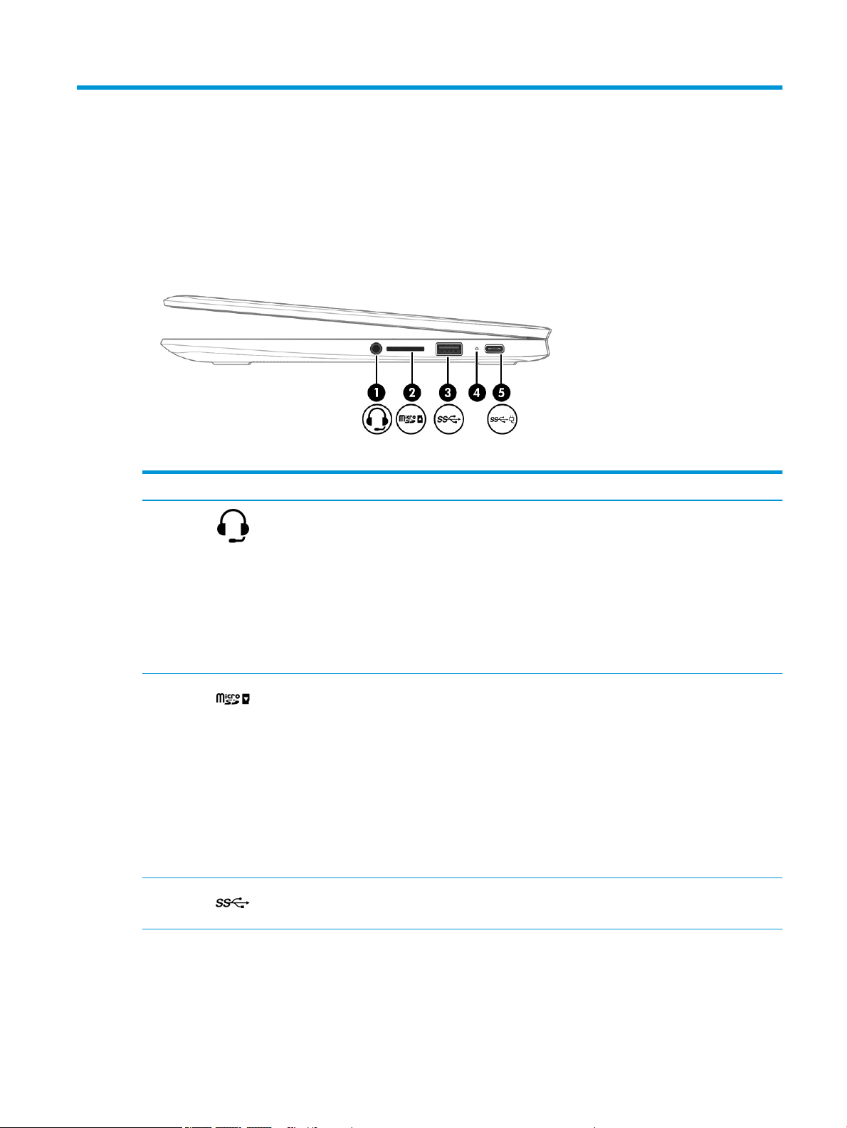
Right side
Table 2-1 Right-side components and their descriptions
Component Description
(1) Audio-out (headphone)/Audio-in
(microphone) combo jack
(2) MicroSD™ memory card reader Reads optional memory cards that enable you to store,
(3) USB SuperSpeed port Connects a USB device, such as a cell phone, camera, activity
Connects optional powered stereo speakers, headphones,
earbuds, a headset, or a television audio cable. Also connects
an optional headset microphone. This jack does not support
optional standalone microphones.
WARNING! To reduce the risk of personal injury, adjust
the volume before putting on headphones, earbuds, or a
headset. For additional safety information, see the Regulatory,
Safety, and Environmental Notices.
NOTE: When a device is connected to the jack, the computer
speakers are disabled.
manage, share, or access information.
To insert a card:
1. Hold the card label-side up, with connectors facing
the computer.
2. Insert the card into the memory card reader, and then
press in on the card until it is rmly seated.
To remove a card:
▲ Press in on the card, and then remove it from
the memory card reader.
tracker, or smartwatch, and provides high-speed data transfer.
(4) AC adapter and battery light ● White: The AC adapter is connected and the battery
is fully charged.
● Amber: The AC adapter is connected and the battery
is charging.
Right side 3
Page 10

Table 2-1 Right-side components and their descriptions (continued)
Component Description
● Blinking amber: The battery has an error.
● O: The battery is not charging.
(5) USB Type-C power connector and super
speed port
Connects an AC adapter that has a USB Type-C connector,
supplying power to the computer and, if needed, charging
the computer battery.
– and –
Connects a USB device that has a Type-C connector, such as a
cell phone, camera, activity tracker, or smartwatch, and
provides data transfer.
– and –
Connects a display device that has a USB Type-C connector,
providing DisplayPort™ output.
NOTE: Cables, adapters, or both (purchased separately) may
be required.
4 Chapter 2 Components
Page 11
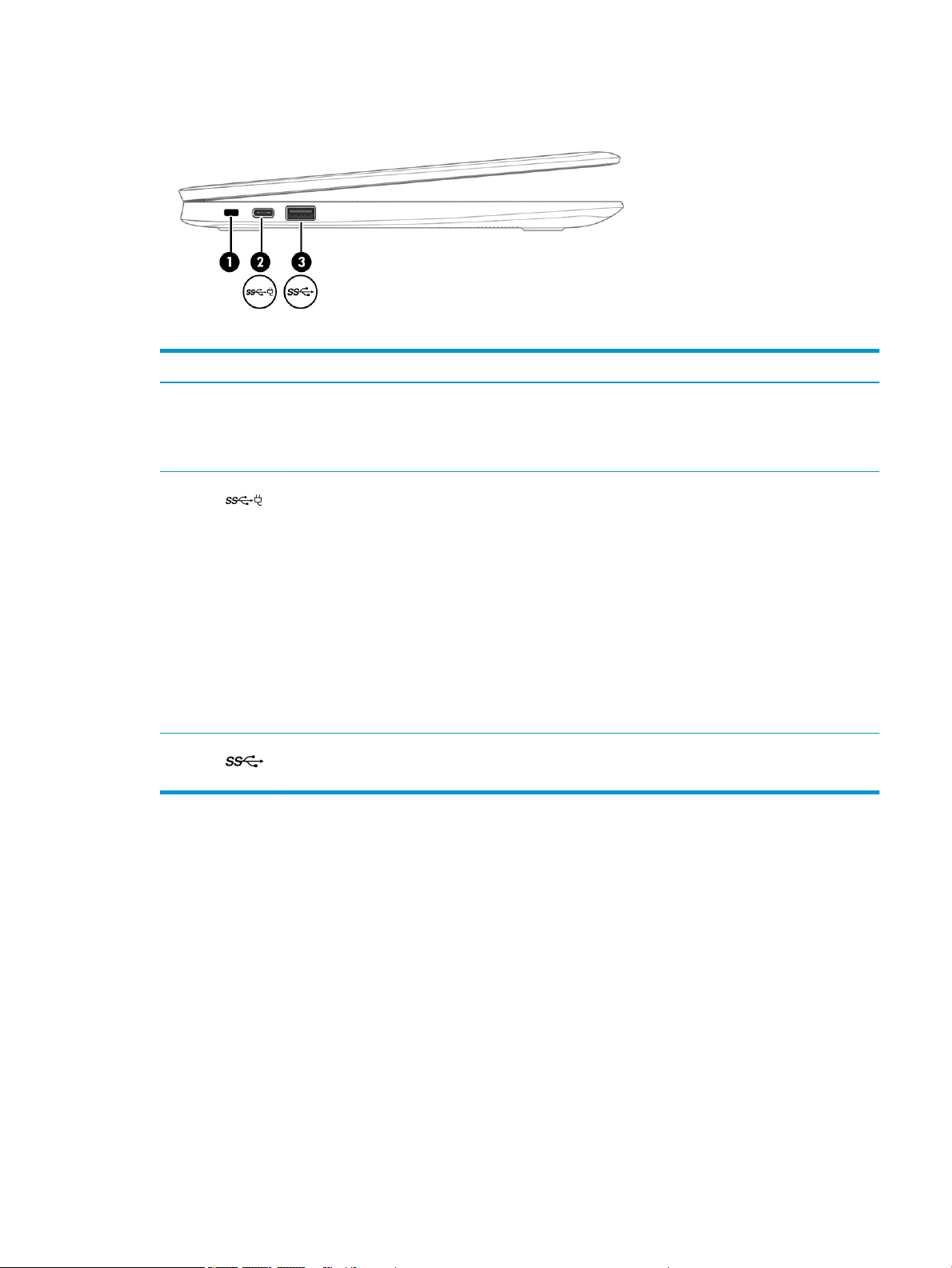
Left side
Table 2-2 Left-side components and their descriptions
Component Description
(1) Nano security cable slot Attaches an optional security cable to the computer.
NOTE: The security cable is designed to act as a deterrent,
but it may not prevent the computer from being mishandled
or stolen.
(2) USB Type C Power Connector and Super Speed
port.
(3) USB SuperSpeed port Connects a USB device, such as a cell phone, camera, activity
Connects an AC adapter that has a USB Type-C connector,
supplying power to the computer and, if needed, charging
the computer battery.
– and –
Connects a USB device that has a Type-C connector, such as a
cell phone, camera, activity tracker, or smartwatch, and
provides data transfer.
– and –
Connects a display device that has a USB Type-C connector,
providing DisplayPort output.
NOTE: Cables, adapters, or both (purchased separately) may
be required.
tracker, or smartwatch, and provides high-speed data transfer.
Left side 5
Page 12
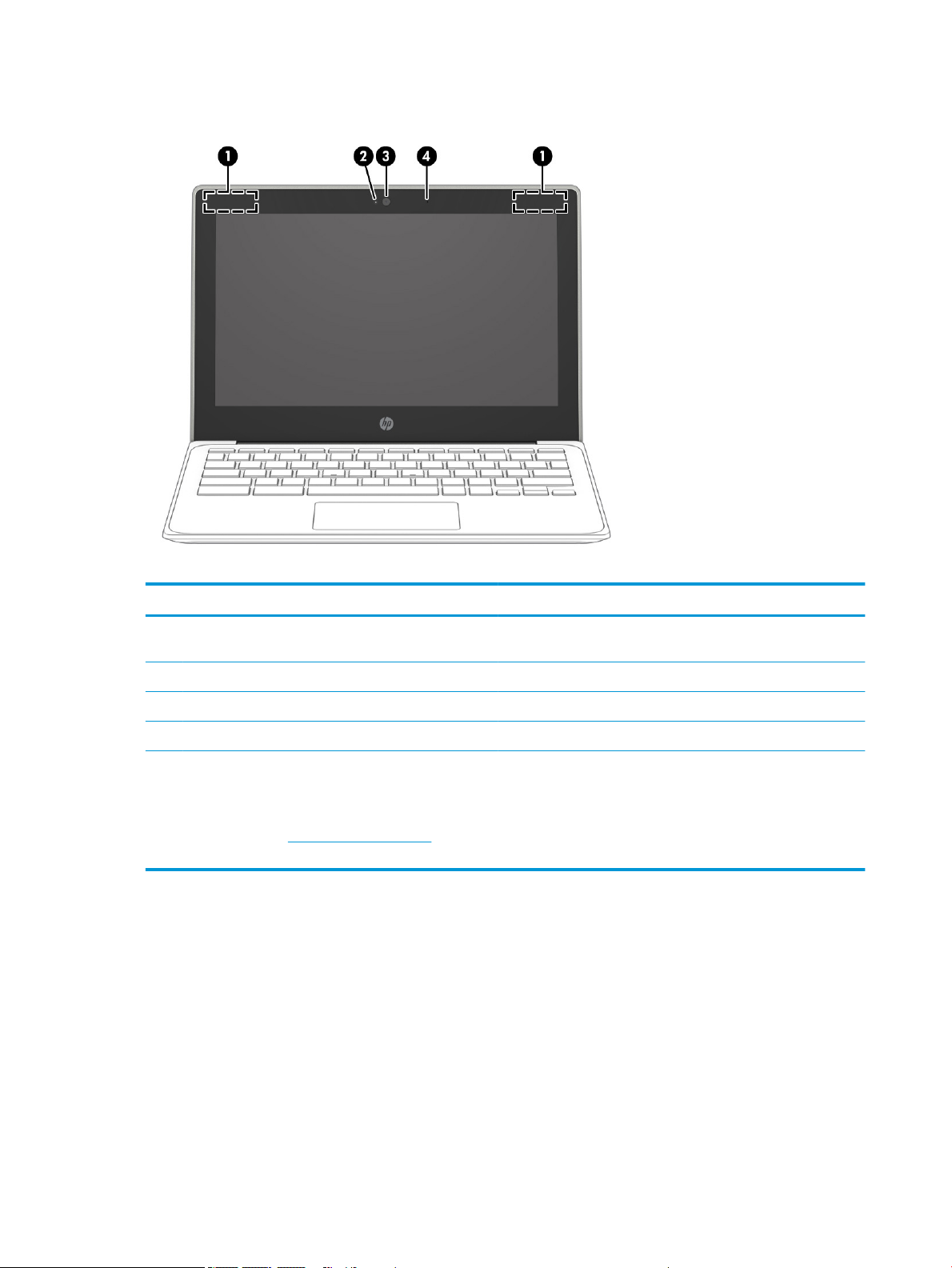
Display
Table 2-3 Display components and their descriptions
Component Description
(1) WLAN antennas* Send and receive wireless signals to communicate with wireless local
area networks (WLANs).
(2) Camera light On: The camera is in use.
(3) Camera Allows you to video chat, record video, and record still images.
(4) Internal microphone Record sound.
*The antennas are not visible from the outside of the computer, and antenna location varies. For optimal transmission, keep the areas
immediately around the antennas free from obstructions.
For wireless regulatory notices, see the section of the Regulatory, Safety, and Environmental Notices that applies to your country or region.
To access this guide, go to http://www.hp.com/support, type HP Documentation in the taskbar search box, and then select
HP Documentation.
6 Chapter 2 Components
Page 13
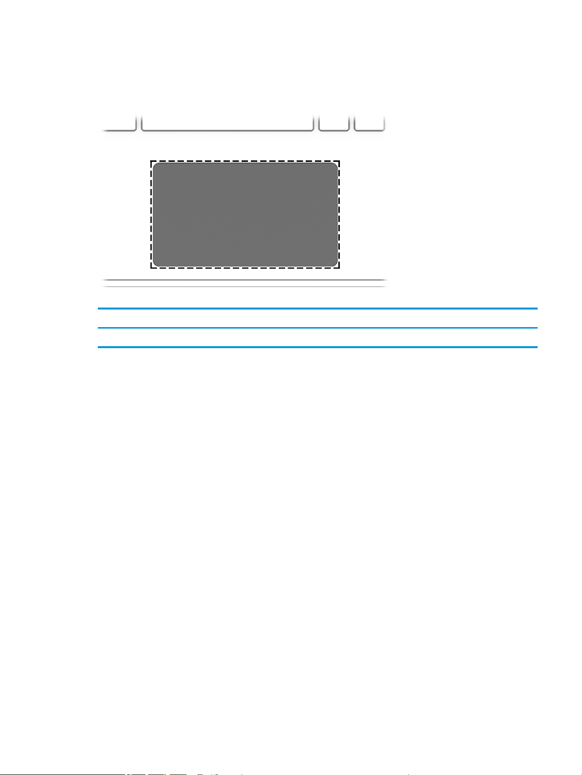
Keyboard area
touchpad
Table 2-4 Touchpad components and their descriptions
Component Description
Touchpad zone Reads your nger gestures to move the pointer or activate items on the screen.
Keyboard area 7
Page 14
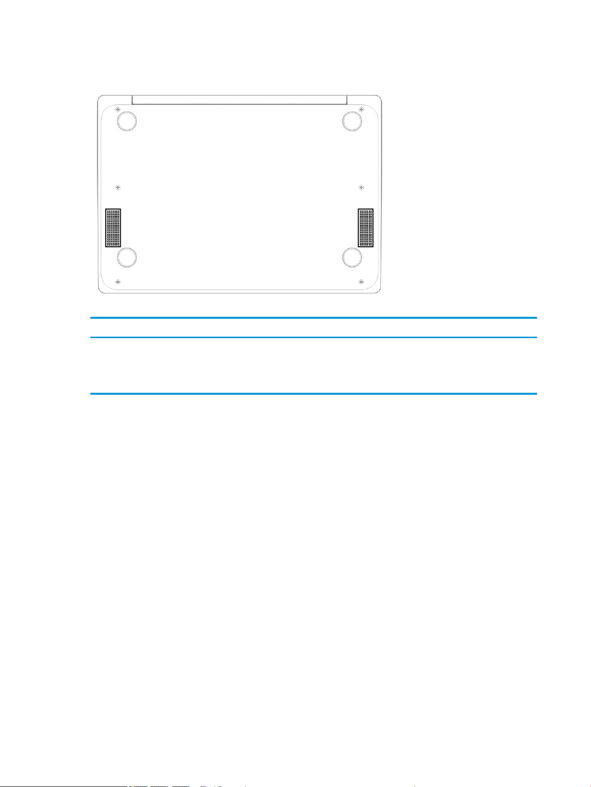
Bottom
Table 2-5 Bottom components and their descriptions
Components Description
Speaker vents Enable airow to cool internal components.
NOTE: The computer fan starts up automatically to cool internal
components and prevent overheating. It is normal for the internal fan to cycle
on and o during routine operation.
8 Chapter 2 Components
Page 15
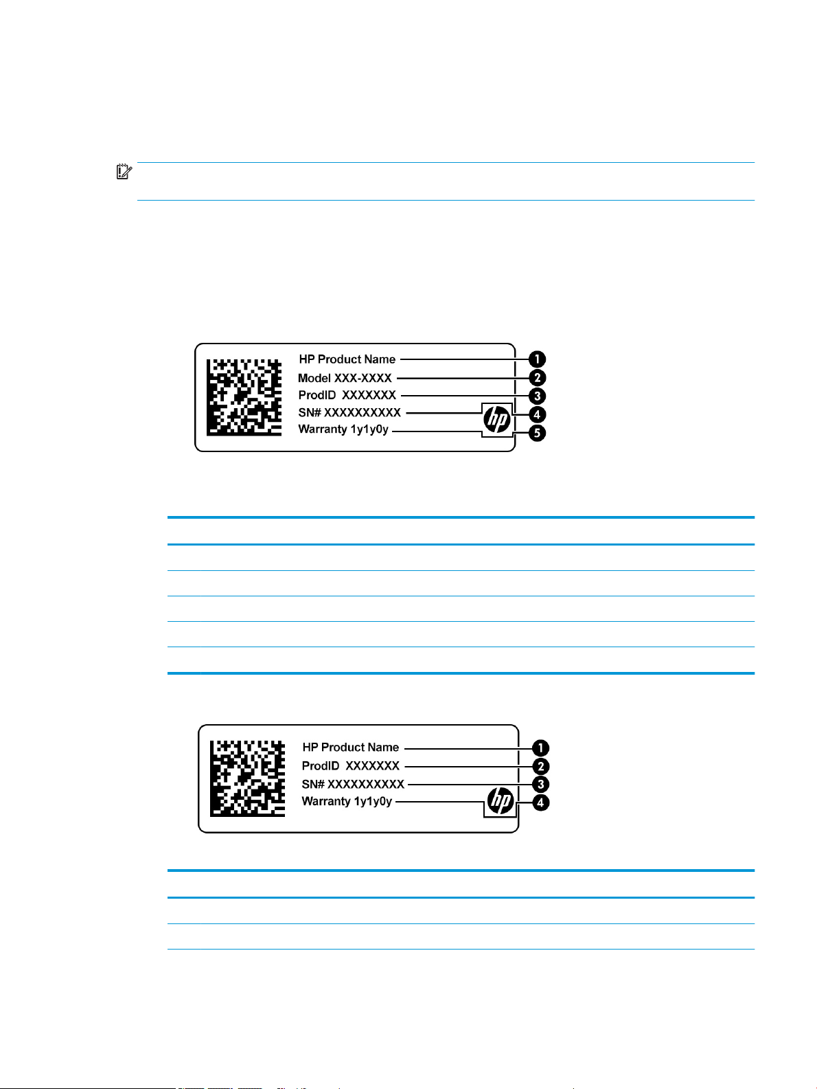
Labels
The labels axed to the computer provide information you may need when you troubleshoot system problems
or travel internationally with the computer. Labels may be in paper form or imprinted on the product.
IMPORTANT: Check the following locations for the labels described in this section: the bottom of the computer,
inside the battery bay, under the service door, on the back of the display, or on the bottom of a tablet kickstand.
● Service label—Provides important information to identify your computer. When contacting support, you
may be asked for the serial number, the product number, or the model number. Locate this information
before you contact support.
Your service label will resemble one of the following examples. Refer to the illustration that most closely
matches the service label on your computer.
Table 2-6 Service label components
Component
(1) HP product name
(2) Model number
(3) Product ID
(4) Serial number
(5) Warranty period
Table 2-7 Service label components
Component
(1) HP product name
(2) Product ID
Labels 9
Page 16

Table 2-7 Service label components (continued)
Component
(3) Serial number
(4) Warranty period
● Regulatory label(s)—Provide(s) regulatory information about the computer.
● Wireless certication label(s)—Provide(s) information about optional wireless devices and the approval
markings for the countries or regions in which the devices have been approved for use.
10 Chapter 2 Components
Page 17
3 Illustrated parts catalog
NOTE: HP continually improves and changes product parts. For complete and current information on
supported parts for your computer, go to http://partsurfer.hp.com, select your country or region, and then follow
the on-screen instructions.
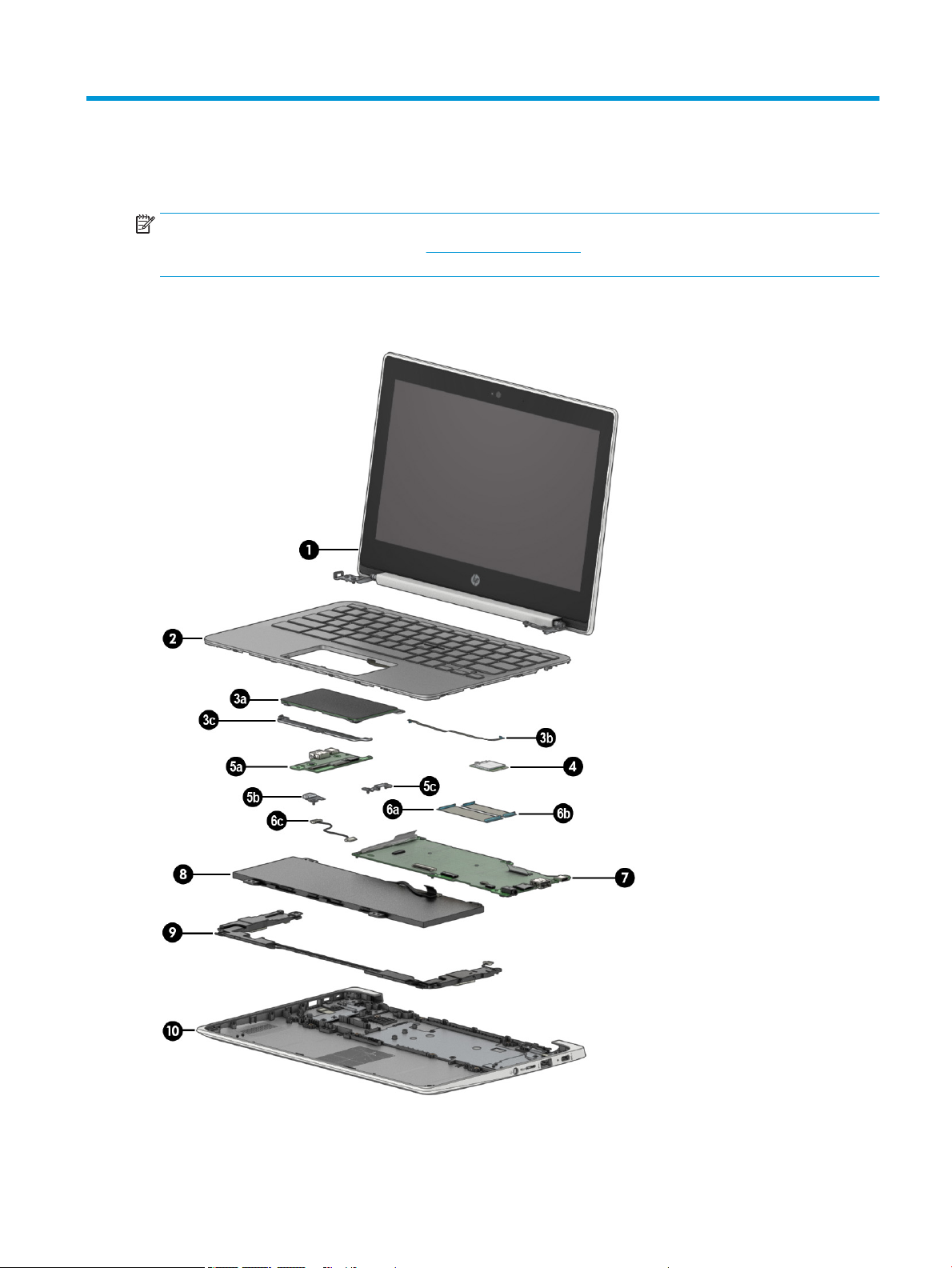
Computer major components
Computer major components 11
Page 18

Table 3-1 Major component spare part information
Item Component Spare part number
(1) Display assembly: The display assembly is spared at the subcomponent level only. For more display assembly spare part
(2) Keyboard/top cover in chalkboard gray nish (includes keyboard cable):
For use in Belgium L90338-A41
For use in Brazil L90338-201
For use in Canada L90338-DB1
For use in the Czech Republic and Slovakia L90338-FL1
For use in Denmark, Finland, and Norway L90338-DH1
For use in France L90338-051
For use in Germany L90338-041
For use in Israel L90338-BB1
For use in Italy L90338-061
For use in Latin America L90338-161
For use in the Netherlands L90338-B31
For use in Portugal L90338-131
For use in Romania L90338-271
For use in Russia L90338-251
information, see Display components on page 15.
For use in Saudi Arabia L90338-171
For use in South Korea L90338-AD1
For use in Spain L90338-071
For use in Switzerland L90338-BG1
For use in Taiwan L90338-AB1
For use in Thailand L90338-281
For use in Turkey L90338-141
For use in the United Kingdom L90338-031
For use in the United States L90338-001
Keyboard/top cover in dark sage gray nish (includes keyboard cable):
For use in Belgium L90339-A41
For use in Brazil L90339-261
For use in Canada L90339-DB1
For use in the Czech Republic and Slovakia L90339-FL1
For use in Denmark, Finland, and Norway L90339-DH1
For use in France L90339-051
For use in Germany L90339-041
12 Chapter 3 Illustrated parts catalog
Page 19

Table 3-1 Major component spare part information (continued)
Item Component Spare part number
For use in Israel L90339-BB1
For use in Italy L90339-061
For use in Latin America L90339-161
For use in the Netherlands L90339-B31
For use in Portugal L90339-131
For use in Romania L90339-271
For use in Russia L90339-251
For use in Saudi Arabia L90339-171
For use in South Korea L90339-AD1
For use in Spain L90339-071
For use in Switzerland L90339-BG1
For use in Taiwan L90339-AB1
For use in Thailand L90339-281
For use in Turkey L90339-141
For use in the United Kingdom L90339-031
For use in the United States L90339-001
(3a) Touchpad:
In chalkboard gray nish L89789-001
In dark sage gray nish L89790-001
(3b) Touchpad cable (included in the Cable Kit, spare part number L89767-001)
(3c) Touchpad bracket L89791-001
(4) Intel 9560 ac 2×2 + Bluetooth 5.0 MU-MIMO M.2 2230 non-vPro WLAN module L41693-005
WLAN bracket (not illustrated) M00452-001
(5a) Connector board (includes audio jack and USB port) L89792-001
(5b) Left-side I/O bracket L89793-001
(5c) Right-side I/O bracket L89793-001
(6a) Connector board high-speed cable (included in the Cable Kit, spare part number L89767-001)
(6b) Connector board low-speed cable (included in the Cable Kit, spare part number L89767-001)
(6c) Power cable (included in the Cable Kit, spare part number L89767-001)
(7) System board (includes processor, heat sink, and replacement thermal material):
Equipped with an Intel Celeron N4120 processor, 8 GB of system memory, 64 GB of eMMC system
storage, and the Google Chrome operating system
Equipped with an Intel Celeron N4120 processor, 8 GB of system memory, 32 GB of eMMC system
storage, and the Google Chrome operating system
Computer major components 13
L89782-001
L89781-001
Page 20

Table 3-1 Major component spare part information (continued)
Item Component Spare part number
Equipped with an Intel Celeron N4120 processor, 4 GB of system memory, 32 GB of eMMC system
storage, and the Google Chrome operating system
Equipped with an Intel Celeron N4020 processor, 4 GB of system memory, 64 GB of eMMC system
storage, and the Google Chrome operating system
Equipped with an Intel Celeron N4020 processor, 4 GB of system memory, 32 GB of eMMC system
storage, and the Google Chrome operating system
Equipped with an Intel Celeron N4020 processor, 4 GB of system memory, 16 GB of eMMC system
storage, and the Google Chrome operating system
(8) Battery (2-cell, 47.36-WHr, 6.15-AHr, Li-ion; includes cable) L75783-005
Battery bracket (not illustrated) L98587-001
Battery tape (not illustrated) L14905-001
(9) Speakers (include left and right speakers, cables, and 2 rubber isolators) L89788-001
(10) Bottom cover:
In chalkboard gray nish L89764-001
In dark sage gray nish L89765-001
L89780-001
L89779-001
L89778-001
L89777-001
14 Chapter 3 Illustrated parts catalog
Page 21
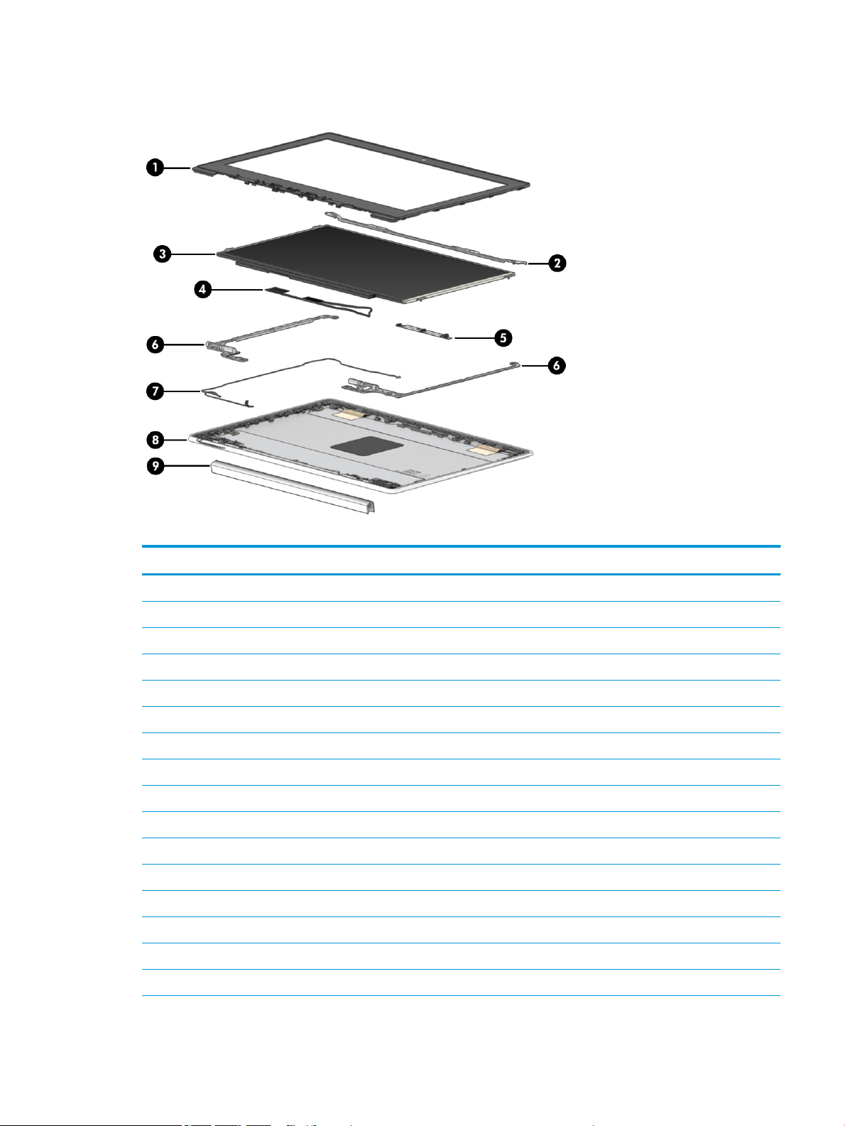
Display components
Table 3-2 Display component spare part information
Item Component Spare part number
(1) Display bezel L89773-001
(2) Display bracket L89774-001
(3) Display panel:
11.6-in, HD, antiglare, LED, UWVA, touchscreen display panel L89785-001
11.6-in, HD, antiglare, LED, UWVA, non-touchscreen display panel L89784-001
11.6-in, HD, antiglare, LED, SVA, non-touchscreen display panel L89783-001
(4) Display panel cable:
For use only on computers equipped with a touchscreen display assembly L89776-001
For use only on computers equipped with a non-touchscreen display assembly L89775-001
(5) Webcam module (includes double-sided adhesive) L51916-001
(6) Display hinges (2) L89768-001
(7) Webcam module cable (included in the Cable Kit, spare part number L89767-001)
(8) Display back cover (includes the wireless antenna cables and transceivers):
In chalkboard gray nish L89771-001
In dark sage gray nish L89772-001
(9) Display hinge cover:
Display components 15
Page 22

Table 3-2 Display component spare part information (continued)
Item Component Spare part number
In chalkboard gray nish L89769-001
In dark sage gray nish L89770-001
16 Chapter 3 Illustrated parts catalog
Page 23

Miscellaneous parts
Table 3-3 Miscellaneous spare part information
Component Spare part number
45-W, AC Adapter (non-PFC, USB Type-C, 1.8-m, 3-pin) L43407-001
Cable Kit (includes adapter cable, connector board high-speed cable, connector board low-speed cable, touchpad
cable, and webcam module cable)
Power cord (C5, 1.0-m, conventional with sticker):
For use in Argentina L19357-001
For use in Australia L19358-001
For use in Brazil L19359-001
For use in Denmark L19360-001
For use in Europe L19361-001
For use in India L19363-001
For use in Israel L19362-001
For use in Italy L19364-001
For use in North America L19367-001
For use in South Africa L19369-001
For use in South Korea L19366-001
For use in Switzerland L19370-001
For use in Taiwan L19372-001
For use in Thailand L19371-001
L89767-001
For use in the United Kingdom L19373-001
Rubber Kit (includes touchpad bracket bumper) L89786-001
Screw Kit L89787-001
Miscellaneous parts 17
Page 24

4 Removal and replacement procedures
preliminary requirements
Tools required
You will need the following tools to complete the removal and replacement procedures:
● Flat-bladed screwdriver
● Magnetic screwdriver
● Phillips P0 and P1 screwdrivers
Service considerations
The following sections include some of the considerations that you must keep in mind during disassembly
and assembly procedures.
NOTE: As you remove each subassembly from the computer, place the subassembly (and all accompanying
screws) away from the work area to prevent damage.
Plastic parts
IMPORTANT: Using excessive force during disassembly and reassembly can damage plastic parts. Use care
when handling the plastic.
Cables and connectors
IMPORTANT: When servicing the computer, be sure that cables are placed in their proper locations during
the reassembly process. Improper cable placement can damage the computer.
Cables must be handled with extreme care to avoid damage. Apply only the tension required to unseat or seat
the cables during removal and insertion. Handle cables by the connector whenever possible. In all cases, avoid
bending, twisting, or tearing cables. Be sure that cables are routed in such a way that they cannot be caught
or snagged by parts being removed or replaced. Handle ex cables with extreme care; these cables tear easily.
18 Chapter 4 Removal and replacement procedures preliminary requirements
Page 25

Drive handling
IMPORTANT: Drives are fragile components that must be handled with care. To prevent damage to
the computer, damage to a drive, or loss of information, observe these precautions:
● Before removing or inserting a hard drive, shut down the computer. If you are unsure whether
the computer is o or in Hibernation, turn the computer on, and then shut it down through
the operating system.
● Before handling a drive, be sure that you are discharged of static electricity. While handling a drive, avoid
touching the connector.
● Before removing an optical drive, be sure that a disc is not in the drive and be sure that the optical drive
tray is closed.
● Handle drives on surfaces covered with at least 2.54 cm (one in.) of shock-proof foam.
● Avoid dropping drives from any height onto any surface.
● After removing a hard drive or an optical drive, place it in a static-proof bag.
● Avoid exposing an internal hard drive to products that have magnetic elds, such as monitors or speakers.
● Avoid exposing a drive to temperature extremes or liquids.
● If a drive must be mailed, place the drive in a bubble pack mailer or other suitable form of protective
packaging and label the package “FRAGILE.”
Electrostatic discharge damage
Electronic components are sensitive to electrostatic discharge (ESD). Circuitry design and structure determine
the degree of sensitivity. Networks built into many integrated circuits provide some protection, but in
many cases, ESD contains enough power to alter device parameters or melt silicon junctions.
A discharge of static electricity from a nger or other conductor can destroy static-sensitive devices
or microcircuitry. Even if the spark is neither felt nor heard, damage may have occurred.
An electronic device exposed to ESD may not be aected at all and can work perfectly throughout a normal
cycle. Or the device may function normally for a while, then degrade in the internal layers, reducing its
life expectancy.
IMPORTANT: To prevent damage to the tablet when you are removing or installing internal components,
observe these precautions:
● Keep components in their electrostatic-safe containers until you are ready to install them.
● Before touching an electronic component, discharge static electricity by using the guidelines described in
this section.
● Avoid touching pins, leads, and circuitry. Handle electronic components as little as possible.
● If you remove a component, place it in an electrostatic-safe container.
The following table shows how humidity aects the electrostatic voltage levels generated by dierent activities.
IMPORTANT: A product can be degraded by as little as 700 V.
Electrostatic discharge damage 19
Page 26

Table 4-1 Typical electrostatic voltage levels
Typical electrostatic voltage levels
Relative humidity
Event 10% 40% 55%
Walking across carpet 35,000 V 15,000 V 7,500 V
Walking across vinyl oor 12,000 V 5,000 V 3,000 V
Motions of bench worker 6,000 V 800 V 400 V
Removing DIPS from plastic tube 2,000 V 700 V 400 V
Removing DIPS from vinyl tray 11,500 V 4,000 V 2,000 V
Removing DIPS from polystyrene foam 14,500 V 5,000 V 3,500 V
Removing bubble pack from PCB 26,500 V 20,000 V 7,000 V
Packing PCBs in foam-lined box 21,000 V 11,000 V 5,000 V
Packaging and transporting guidelines
Follow these grounding guidelines when packaging and transporting equipment:
● To avoid hand contact, transport products in static-safe tubes, bags, or boxes.
● Protect ESD-sensitive parts and assemblies with conductive or approved containers or packaging.
● Keep ESD-sensitive parts in their containers until the parts arrive at static-free workstations.
● Place items on a grounded surface before removing items from their containers.
● Always be properly grounded when touching a component or assembly.
● Store reusable ESD-sensitive parts from assemblies in protective packaging or nonconductive foam.
● Use transporters and conveyors made of antistatic belts and roller bushings. Be sure that mechanized
equipment used for moving materials is wired to ground and that proper materials are selected to avoid
static charging. When grounding is not possible, use an ionizer to dissipate electric charges.
20 Chapter 4 Removal and replacement procedures preliminary requirements
Page 27

Workstation guidelines
Follow these grounding workstation guidelines:
● Cover the workstation with approved static-shielding material.
● Use a wrist strap connected to a properly grounded work surface and use properly grounded tools
and equipment.
● Use conductive eld service tools, such as cutters, screw drivers, and vacuums.
● When xtures must directly contact dissipative surfaces, use xtures made only of static-safe materials.
● Keep the work area free of nonconductive materials, such as ordinary plastic assembly aids
and polystyrene foam.
● Handle ESD-sensitive components, parts, and assemblies by the case or PCM laminate. Handle these items
only at static-free workstations.
● Avoid contact with pins, leads, or circuitry.
● Turn o power and input signals before inserting or removing connectors or test equipment.
Equipment guidelines
Grounding equipment must include either a wrist strap or a foot strap at a grounded workstation.
● When seated, wear a wrist strap connected to a grounded system. Wrist straps are exible straps with a
minimum of 1 MΩ ±10% resistance in the ground cords. To provide proper ground, wear a strap snugly
against the skin at all times. On grounded mats with banana-plug connectors, use alligator clips to connect
a wrist strap.
● When standing, use foot straps and a grounded oor mat. Foot straps (heel, toe, or boot straps) can be
used at standing workstations and are compatible with most types of shoes or boots. On conductive oors
or dissipative oor mats, use foot straps on both feet with a minimum of 1 MΩ ±10% resistance between
the operator and ground. To be eective, the conductive must be worn in contact with the skin.
The following grounding equipment is recommended to prevent electrostatic damage:
● Antistatic tape
● Antistatic smocks, aprons, and sleeve protectors
● Conductive bins and other assembly or soldering aids
● Nonconductive foam
● Conductive tabletop workstations with ground cords of 1 MΩ ±10% resistance
● Static-dissipative tables or oor mats with hard ties to the ground
● Field service kits
● Static awareness labels
● Material-handling packages
● Nonconductive plastic bags, tubes, or boxes
● Metal tote boxes
● Electrostatic voltage levels and protective materials
Workstation guidelines 21
Page 28

The following table lists the shielding protection provided by antistatic bags and oor mats.
Table 4-2 Shielding protection provided by antistatic bags and oor mats
Material Use Voltage protection level
Antistatic plastics Bags 1,500 V
Carbon-loaded plastic Floor mats 7,500 V
Metallized laminate Floor mats 5,000 V
22 Chapter 4 Removal and replacement procedures preliminary requirements
Page 29

5 Removal and replacement procedures
CAUTION: Components described in this chapter should only be accessed by an authorized service provider.
Accessing these parts can damage the computer or void the warranty.
NOTE: HP continually improves and changes product parts. For complete and current information on
supported parts this your computer, go to http://partsurfer.hp.com, select your country or region, and then
follow the on-screen instructions.
Component replacement procedures
There are as many as 53 screws that must be removed, replaced, and/or loosened when servicing the computer.
Make special note of each screw size and location during removal and replacement.
Keyboard/top cover
Table 5-1 Keyboard/top cover spare part information
For use in country
or region
Keyboard/top cover with backlight
(includes backlight cable and
keyboard cable):
For use in Belgium L90338-A41 For use in Italy L90338-061 For use in Spain L90338-071
For use in Brazil L90338-201 For use in
For use in Canada L90338-DB1 For use in
For use in the Czech
Republic and
Slovakia
For use in Denmark,
Finland, and Norway
For use in France L90338-051 For use in Russia L90338-251 For use in
For use in Germany L90338-041 For use in Saudi Arabia L90338-171 For use in
Keyboard/top cover without backlight
(includes keyboard cable):
Spare part number For use in country
or region
For use in Israel L90338-BB1 For use in South Korea L90338-AD1
Latin America
the Netherlands
L90338-FL1 For use in Portugal L90338-131 For use in Thailand L90338-281
L90338-DH1 For use in Romania L90338-271 For use in Turkey L90338-141
For use in Israel L90339-BB1 For use in South Korea L90339-AD1
Spare part number For use in country
or region
L90338-161 For use in Switzerland L90338-BG1
L90338-B31 For use in Taiwan L90338-AB1
the United Kingdom
the United States
Spare part number
L90338-031
L90338-001
For use in Belgium L90339-A41 For use in Italy L90339-061 For use in Spain L90339-071
For use in Brazil L90339-201 For use in
Latin America
For use in Canada L90339-DB1 For use in
the Netherlands
L90339-161 For use in Switzerland L90339-BG1
L90339-B31 For use in Taiwan L90339-AB1
Component replacement procedures 23
Page 30

Table 5-1 Keyboard/top cover spare part information (continued)
For use in country
or region
For use in the Czech
Republic
and Slovakia
For use in Denmark,
Finland, and Norway
For use in France L90339-051 For use in Russia L90339-251 For use in
For use in Germany L90339-041 For use in Saudi Arabia L90339-171 For use in
Spare part number For use in country
or region
L90339-FL1 For use in Portugal L90339-131 For use in Thailand L90339-281
L90339-DH1 For use in Romania L90339-271 For use in Turkey L90339-141
Spare part number For use in country
or region
the United Kingdom
the United States
Spare part number
L90339-031
L90339-001
Remove the keyboard/top cover:
1. Shut down the computer. If you are unsure whether the computer is o or in Hibernation, turn
the computer on, and then shut it down through the operating system.
2. Disconnect all external devices connected to the computer.
3. Disconnect the power from the computer by rst unplugging the power cord from the AC outlet, and then
unplugging the AC adapter from the computer.
4. Close the computer and position it upside down.
5. Remove the two Phillips M2.5×8.7 screws (1) the four Phillips M2.5×7.2 screws (2) that secure
the keyboard/top cover to the bottom cover.
6. Open the computer and rest it on its left side.
24 Chapter 5 Removal and replacement procedures
Page 31

7. Use a thin plastic tool (1) to separate the rear edge of the keyboard/top cover (2) from the bottom cover.
8. Position the computer right side up with the rear toward you.
9. Open the computer as far as it will open.
10. Lift the rear edge of the keyboard/top cover (1) as far as the keyboard cable and touchpad cable allow.
11. Release the zero insertion force (ZIF) connector (2) to which the touchpad board cable is connected, and
then disconnect the touchpad cable from the system board.
12. Release the shielding (3) that covers the keyboard cable ZIF connector.
13. Release the ZIF connector (4) to which the keyboard cable is connected, and then disconnect the keyboard
cable from the system board.
Component replacement procedures 25
Page 32

14. Remove the keyboard/top cover (5).
Reverse this procedure to install the keyboard/top cover.
26 Chapter 5 Removal and replacement procedures
Page 33
Touchpad cable
NOTE: The touchpad cable is included in the Cable Kit, spare part number L89767-001.
Before removing the touchpad cable, follow these steps:
1. Shut down the computer. If you are unsure whether the computer is o or in Hibernation, turn
the computer on, and then shut it down through the operating system.
2. Disconnect all external devices connected to the computer.
3. Disconnect the power from the computer by rst unplugging the power cord from the AC outlet, and then
unplugging the AC adapter from the computer.
4. Remove the keyboard/top cover (see Keyboard/top cover on page 23).
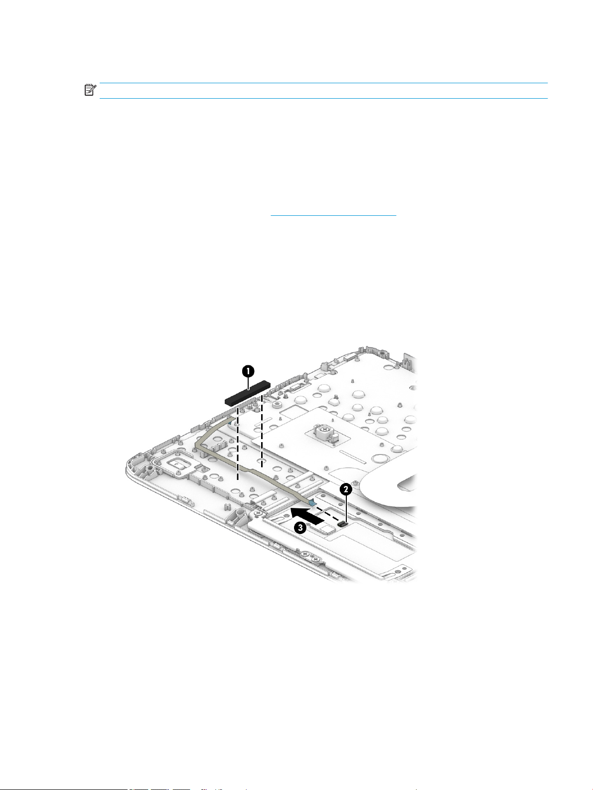
Remove the touchpad cable:
1. Turn the keyboard/top cover upside down with the front toward you.
2. Remove the pad (1) that secures the touchpad cable to the keyboard/top cover.
3. Release the ZIF connector (2) to which the touchpad cable is connected, and then disconnect the touchpad
cable from the touchpad.
4. Remove the touchpad cable (3).
Reverse this procedure to install the touchpad cable.
Component replacement procedures 27
Page 34

Touchpad
Table 5-2 Touchpad spare part information
Before removing the touchpad, follow these steps:
1. Shut down the computer. If you are unsure whether the computer is o or in Hibernation, turn
2. Disconnect all external devices connected to the computer.
3. Disconnect the power from the computer by rst unplugging the power cord from the AC outlet, and then
4. Remove the keyboard/top cover (see Keyboard/top cover on page 23).
Remove the touchpad:
1. Turn the keyboard/top cover upside down with the front toward you.
2. Remove the pad (1) that secures the touchpad cable to the keyboard/top cover.
Description Spare part number
In chalkboard gray nish L89789-001
In dark sage gray nish L89790-001
the computer on, and then shut it down through the operating system.
unplugging the AC adapter from the computer.
3. Release the shielding (2) that covers the touchpad screws.
4. Remove the three Phillips M2.0×2.2 broad head screws (3) that secure the touchpad to the keyboard/
top cover.
5. Remove the four Phillips M2.0×2.9 screws (4) that secure the touchpad and touchpad bracket to
the keyboard/top cover.
6. Remove the touchpad bracket (5).
The touchpad bracket is available using spare part number L89791-001.
28 Chapter 5 Removal and replacement procedures
Page 35

7. Remove the touchpad (6) and cable.
Reverse this procedure to install the touchpad.
Component replacement procedures 29
Page 36

Speakers
Table 5-3 Speaker spare part information
Description Spare part number
Speakers (include left and right speakers, cables, and 2 rubber isolators) L89788-001
Before removing the speakers, follow these steps:
1. Shut down the computer. If you are unsure whether the computer is o or in Hibernation, turn
the computer on, and then shut it down through the operating system.
2. Disconnect all external devices connected to the computer.
3. Disconnect the power from the computer by rst unplugging the power cord from the AC outlet, and then
unplugging the AC adapter from the computer.
4. Remove the keyboard/top cover (see Keyboard/top cover on page 23).
Remove the speakers:
1. Release the shielding (1) that covers the battery cable and connector.
2. Disconnect the battery cable (2) from the system board.
3. Disconnect the speaker cable (1) from the system board.
4. Release the speaker cable from the routing clips (2) and channel built into the battery.
5. Remove the three Phillips M2.0×4.2 screws (3) that secure the speakers to the bottom cover.
30 Chapter 5 Removal and replacement procedures
Page 37

6. Remove the speakers (4).
Reverse this procedure to install the speakers.
Battery
Table
5-4 Battery spare part information
Description Spare part number
Battery (2-cell, 47.36-WHr, 6.15-AHr, Li-ion; includes cable) L75783-005
Battery bracket L98587-001
Battery tape L14905-001
Before removing the battery, follow these steps:
1. Shut down the computer. If you are unsure whether the computer is o or in Hibernation, turn
the computer on, and then shut it down through the operating system.
2. Disconnect all external devices connected to the computer.
3. Disconnect the power from the computer by rst unplugging the power cord from the AC outlet, and then
unplugging the AC adapter from the computer.
4. Remove the keyboard/top cover (see Keyboard/top cover on page 23).
5. Remove the speakers (see Speakers on page 30).
Remove the battery:
1. Release the shielding (1) that covers the battery cable and connector.
2. Disconnect the battery cable (2) from the system board.
3. Remove the two Phillips M2.0×4.2 screws (3) that secure the battery to the bottom cover.
Component replacement procedures 31
Page 38
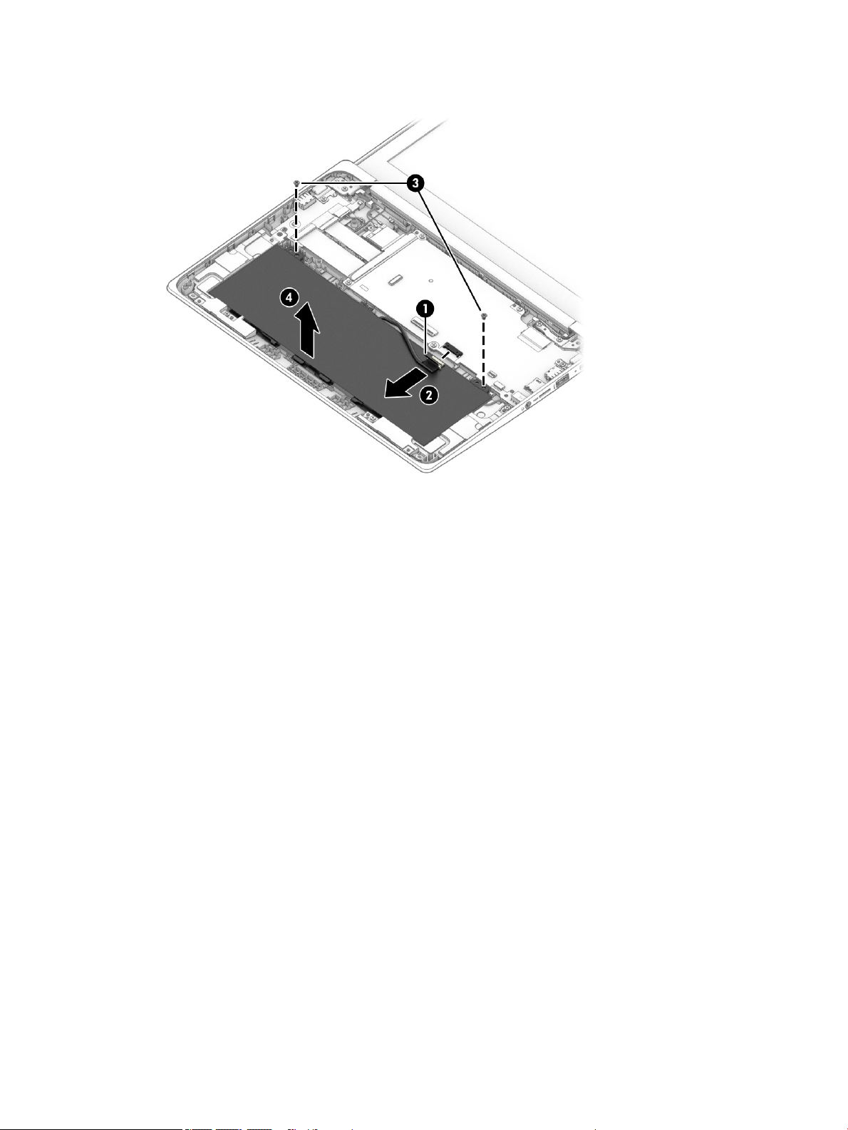
4. Remove the battery (4).
Reverse this procedure to install the battery.
32 Chapter 5 Removal and replacement procedures
Page 39

WLAN module
Table 5-5 WLAN module spare part information
Description Spare part number
Intel 9560 ac 2×2 + Bluetooth 5.0 MU-MIMO M.2 2230 non-vPro WLAN module L41693-005
WLAN bracket M00452-001
CAUTION: To prevent an unresponsive system, replace the wireless module only with a wireless module
authorized for use in the computer by the governmental agency that regulates wireless devices in your country
or region. If you replace the module and then receive a warning message, remove the module to restore device
functionality, and then contact technical support.
Before removing the WLAN module, follow these steps:
1. Shut down the computer. If you are unsure whether the computer is o or in Hibernation, turn
the computer on, and then shut it down through the operating system.
2. Disconnect all external devices connected to the computer.
3. Disconnect the power from the computer by rst unplugging the power cord from the AC outlet, and then
unplugging the AC adapter from the computer.
4. Remove the keyboard/top cover (see Keyboard/top cover on page 23).
5. Disconnect the battery cable from the system board (see Battery on page 31).
Remove the WLAN module:
1. Disconnect the WLAN antenna cables (1) from the terminals on the WLAN module.
NOTE: The #1/white WLAN antenna cable connects to the WLAN module #1/Main terminal. The #2/ black
WLAN antenna cable connects to the WLAN module #2/Aux terminal.
2. Remove the Phillips M2.0×2.9 screw (2) that secures the WLAN module to the system board. (The WLAN
module tilts up.)
3. Release the shielding (3) that secures the WLAN module to the slot.
Component replacement procedures 33
Page 40

4. Remove the WLAN module (4) by pulling the module away from the slot at an angle.
NOTE: WLAN modules are notched to prevent incorrect installation.
Reverse this procedure to install the WLAN module.
34 Chapter 5 Removal and replacement procedures
Page 41

Connector board cables
NOTE: The connector board cables are included in the Cable Kit, spare part number L89767-001.
Before removing the connector board cables, follow these steps:
1. Shut down the computer. If you are unsure whether the computer is o or in Hibernation, turn
the computer on, and then shut it down through the operating system.
2. Disconnect all external devices connected to the computer.
3. Disconnect the power from the computer by rst unplugging the power cord from the AC outlet, and then
unplugging the AC adapter from the computer.
4. Remove the keyboard/top cover (see Keyboard/top cover on page 23).
5. Disconnect the battery cable from the system board (see Battery on page 31).
Remove the connector board cables:
1. Release the shielding (1) that covers the connector board cable ZIF connectors.
2. Release the ZIF connectors (2) to which the connector board cables are connected, and then disconnect
the connector board cables from the system board.
3. Release the ZIF connectors (3) to which the connector board cables are connected, and then disconnect
the connector board cables from the connector board.
4. Remove the connector board cables (4).
Reverse this procedure to install the connector board cables.
Component replacement procedures 35
Page 42

Connector board
Table 5-6 Connector board spare part information
Description Spare part number
Connector board (includes audio jack and USB port and rubber bumper) L89792-001
Before removing the connector board, follow these steps:
1. Shut down the computer. If you are unsure whether the computer is o or in Hibernation, turn
the computer on, and then shut it down through the operating system.
2. Disconnect all external devices connected to the computer.
3. Disconnect the power from the computer by rst unplugging the power cord from the AC outlet, and then
unplugging the AC adapter from the computer.
4. Remove the keyboard/top cover (see Keyboard/top cover on page 23).
5. Disconnect the battery cable from the system board (see Battery on page 31).
Remove the connector board:
1. Release the shielding (1) that covers the connector board cable ZIF connectors on the system board.
2. Release the ZIF connectors (2) to which the connector board cables are connected, and then disconnect
the connector board cables from the system board.
3. Release the shielding (3) that covers the power cable connector.
4. Disconnect the power cable (4) from the connector board.
5. Remove the two Phillips M2.0×4.2 screws (5) that secure the connector board to the bottom cover.
6. Remove the left-side I/O bracket (6).
The left-side I/O bracket is available using spare part number L89793-001.
36 Chapter 5 Removal and replacement procedures
Page 43

7. Remove the connector board (7) and cables.
Reverse this procedure to install the connector board.
Component replacement procedures 37
Page 44

System board
NOTE: The system board spare part kit includes the processor, heat sink, and replacement thermal material.
Table 5-7 System board spare part information
Description Spare part number
Equipped with an Intel Celeron N4120 processor, 8 GB of system memory, 64 GB of eMMC system storage, and
the Google Chrome operating system
Equipped with an Intel Celeron N4120 processor, 8 GB of system memory, 32 GB of eMMC system storage, and
the Google Chrome operating system
Equipped with an Intel Celeron N4120 processor, 4 GB of system memory, 32 GB of eMMC system storage, and
the Google Chrome operating system
Equipped with an Intel Celeron N4020 processor, 4 GB of system memory, 64 GB of eMMC system storage, and
the Google Chrome operating system
Equipped with an Intel Celeron N4020 processor, 4 GB of system memory, 32 GB of eMMC system storage, and
the Google Chrome operating system
Equipped with an Intel Celeron N4020 processor, 4 GB of system memory, 16 GB of eMMC system storage, and
the Google Chrome operating system
L89782-001
L89781-001
L89780-001
L89779-001
L89778-001
L89777-001
Before removing the system board, follow these steps:
1. Shut down the computer. If you are unsure whether the computer is o or in Hibernation, turn
the computer on, and then shut it down through the operating system.
2. Disconnect all external devices connected to the computer.
3. Disconnect the power from the computer by rst unplugging the power cord from the AC outlet, and then
unplugging the AC adapter from the computer.
4. Remove the keyboard/top cover (see Keyboard/top cover on page 23).
5. Disconnect the battery cable from the system board (see Battery on page 31).
6. Remove the WLAN module (see WLAN module on page 33).
Remove the system board:
1. Release the shielding (1) that covers the connector board cable ZIF connectors on the system board.
2. Release the ZIF connectors (2) to which the connector board cables are connected, and then disconnect
the connector board cables from the system board.
3. Release the shielding (3) that covers the power cable connector.
4. Disconnect the power cable (4) from the connector board.
5. Disconnect the webcam module cable (5) from the system board.
6. Release the shielding (6) that covers the display panel cable connector.
7. Disconnect the display panel cable (7) from the system board.
8. Disconnect the speaker cable (8) from the system board.
38 Chapter 5 Removal and replacement procedures
Page 45

9. Release the power cable from the retention clip (9) built into the bottom cover.
10. Remove the six Phillips M2.0×4.2 screws (1) that secure the system board to the bottom cover.
Component replacement procedures 39
Page 46

11. Remove the right-side I/O bracket (2).
The I/O bracket is available using spare part number L89793-001.
12. Lift the left side the system board (1) until it rests at an angle.
13. Remove the system board (2) by sliding it up and to the left at an angle.
Reverse this procedure to install the system board.
40 Chapter 5 Removal and replacement procedures
Page 47

Power cable
NOTE: The power cable is included in the Cable Kit, spare part number L89767-001.
Before removing the power cable, follow these steps:
1. Shut down the computer. If you are unsure whether the computer is o or in Hibernation, turn
2. Disconnect all external devices connected to the computer.
3. Disconnect the power from the computer by rst unplugging the power cord from the AC outlet, and then
4. Remove the keyboard/top cover (see Keyboard/top cover on page 23).
5. Disconnect the battery cable from the system board (see Battery on page 31).
6. Remove the WLAN module (see WLAN module on page 33).
7. Remove the system board (see System board on page 38).
Remove the power cable:
1. Turn the system board upside down with the rear toward you.
2. Disconnect the power cable from the system board.
the computer on, and then shut it down through the operating system.
unplugging the AC adapter from the computer.
Reverse this procedure to install the power cable.
Component replacement procedures 41
Page 48

Display assembly
NOTE: The display assembly is spared at the subcomponent level only. See the removal section for each
component for information.
Before removing the display assembly, follow these steps:
1. Shut down the computer. If you are unsure whether the computer is o or in Hibernation, turn
the computer on, and then shut it down through the operating system.
2. Disconnect all external devices connected to the computer.
3. Disconnect the power from the computer by rst unplugging the power cord from the AC outlet, and then
unplugging the AC adapter from the computer.
4. Remove the keyboard/top cover (see Keyboard/top cover on page 23).
5. Disconnect the battery from the system board (see Battery on page 31).
Remove the display assembly:
1. Remove the display hinge cover by following these steps:
a. Close the computer.
b. Turn the computer upside down with the front toward you.
c. Use a case utility tool (1) or similar thin, plastic tool to separate the left (2) and right edges of
the hinge cover from the display assembly.
d. Remove the hinge cover (3).
The hinge cover is available using spare part numbers L89769-001 (in chalkboard gray nish) and
L89770-001 (in dark sage gray nish).
2. Remove the display bezel by following these steps:
42 Chapter 5 Removal and replacement procedures
Page 49

a. Turn the computer right side up with the rear toward you.
b. Open the computer as far as it will open.
c. Release the top edge of the display bezel (1) from the display assembly.
d. Release the left and right edges of the display bezel (2) from the display assembly.
e. Release the bottom edge of the display bezel (3) from the display assembly.
f. Remove the display bezel (4).
The display bezel is available using spare part number L89773-001.
3. Remove the display bracket by following these steps:
a. Remove the two Phillips M2.0×2.9 screws (1) that secure the display bracket to the display
back cover.
Component replacement procedures 43
Page 50
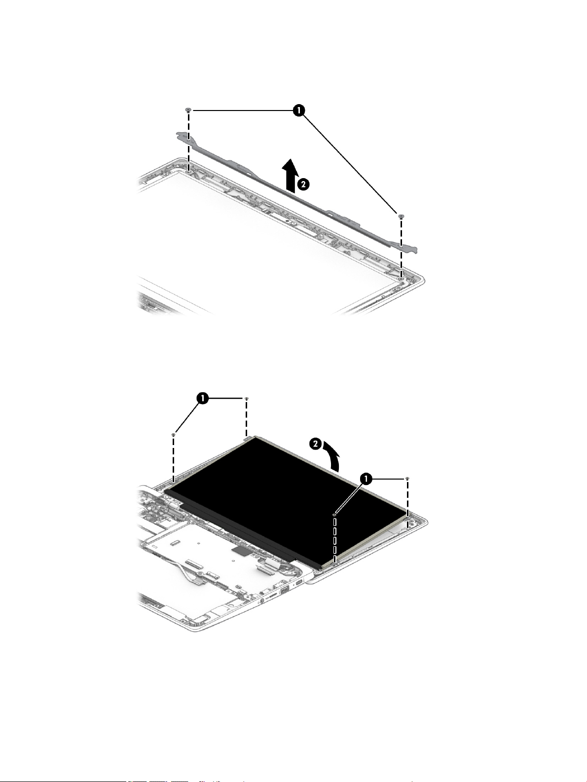
b. Remove the display bracket (2).
The display bracket is available using spare part number L89774-001.
4. Remove the display panel by following these steps:
a. Remove the four Phillips M2.0×2.9 screws (1) that secure the display panel to the display back cover.
b. Swing the top edge (2) of the display panel up and forward until it rests upside down on the computer.
c. Release the adhesive support strip (1) that secures the display panel cable connector to
the display panel.
d. Disconnect the display panel cable (2) from the display panel.
44 Chapter 5 Removal and replacement procedures
Page 51
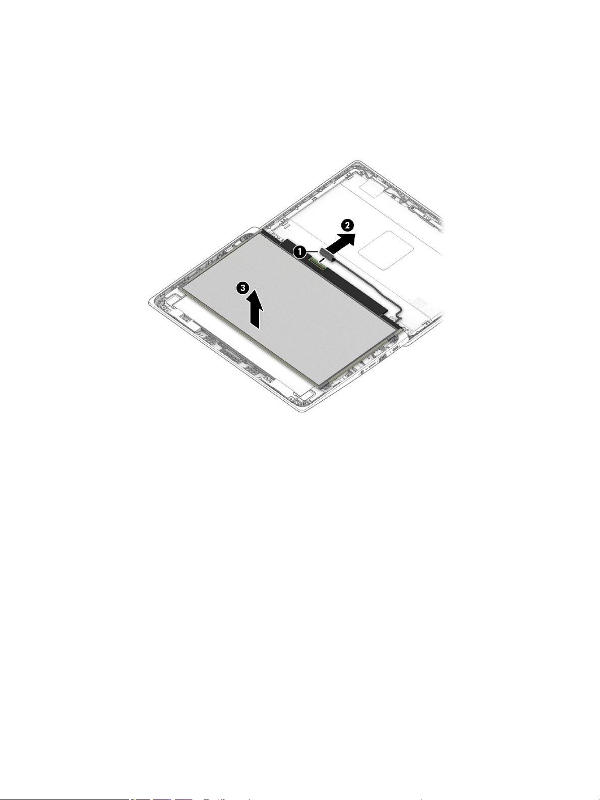
e. Remove the display panel (3).
The display panel is available using the following spare part numbers:
● L89785-001 – 11.6-in, HD, antiglare, LED, UWVA, touchscreen display panel
● L89784-001 – 11.6-in, HD, antiglare, LED, UWVA, non-touchscreen display panel
● L89783-001 – 11.6-in, HD, antiglare, LED, SVA, non-touchscreen display panel
5. Remove the display back cover by following these steps:
a. Remove the six Phillips M2.5×3.0 broad head screws (1) that secure the display back cover to
the display hinges.
Component replacement procedures 45
Page 52
b. Remove the display back cover (2).
The display back cover is available using spare part numbers L89771-001 (in chalkboard gray nish)
and L89772-001 (in dark sage gray nish).
6. Remove the display panel cable by following these steps:
a. Release the display panel cable from the retention clips (1) and routing channel built into the bottom
edge of the display back cover.
46 Chapter 5 Removal and replacement procedures
Page 53
b. Remove the display panel cable (2).
The display panel cable is available using spare part numbers L89776-001 (for use only on
computers equipped with a touchscreen display assembly) and L89775-001 (for use only on
computers equipped with a non-touchscreen display assembly).
7. Remove the webcam module by following these steps:
a. Detach the webcam module (1) from the display back cover. (The webcam module is attached to
the display back cover with double-sided adhesive.)
Component replacement procedures 47
Page 54

b. Release the ZIF connector (2) to which the webcam module cable is connected, and then disconnect
the webcam module cable from the webcam module.
c. Remove the webcam module.
The webcam module is available using spare part number L51916-001.
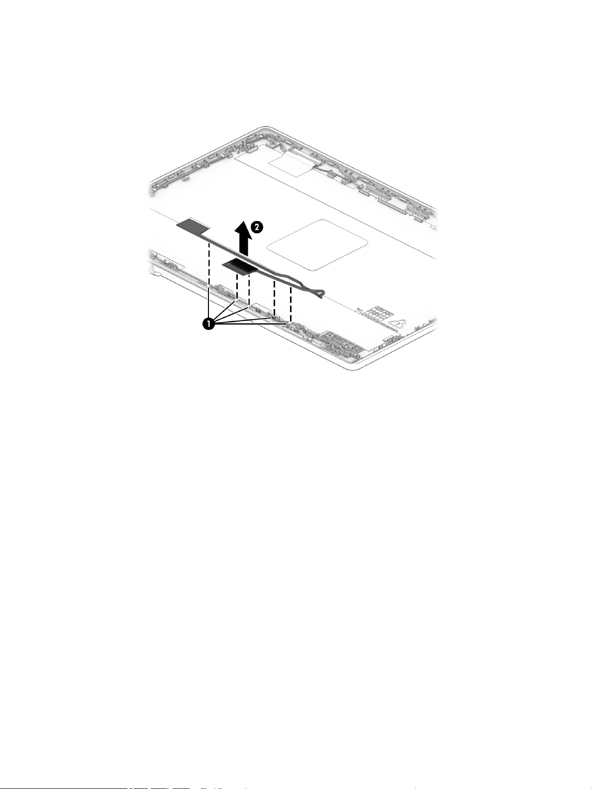
8. Remove the webcam module cable by following these steps:
a. Release the webcam module cable from the retaining clips (1) built into the left hinge area of
the display back cover.
48 Chapter 5 Removal and replacement procedures
Page 55

b. Remove the webcam module cable (2).
The webcam module cable is included in the Cable Kit, spare part number L89767-001.
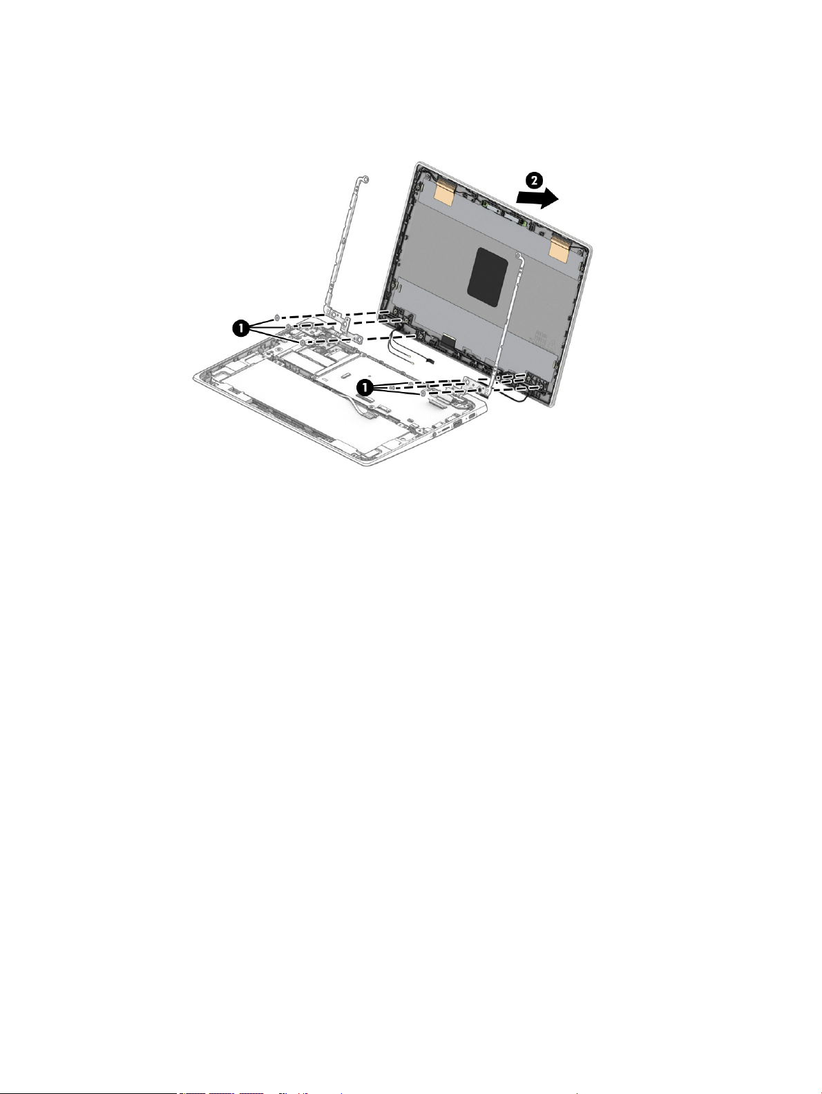
9. Remove the display hinges by following these steps:
a. Remove the four Phillips M2.5×4.7 screws that secure the display hinges to the bottom cover.
b. Slide the hinges (2) forward and remove them.
The display hinges are available using spare part number L89768-001.
Component replacement procedures 49
Page 56

Reverse this procedure to reassemble and install the display assembly.
50 Chapter 5 Removal and replacement procedures
Page 57

6 Specications
Computer specications
The power information in this section may be helpful if you plan to travel internationally with the computer.
The computer operates on DC power, which can be supplied by an AC or a DC power source. The AC power
source must be rated at 100 V–240 V, 50 Hz–60 Hz. Although the computer can be powered from a standalone
DC power source, it should be powered only with an AC adapter or a DC power source that is supplied and
approved by HP for use with this computer.
The computer can operate on DC power within the following specications. Operating voltage and current varies
by platform. The voltage and current for your computer is located on the regulatory label.
Table 6-1 Computer specications
Metric U.S.
Dimensions:
Width 29.5 cm 11.6 in
Depth 20.5 cm 8.1 in
Height 1.9 cm 0.7 in
Weight 1.3 kg 2.9 lbs
Input power Rating
Operating voltage and current 5 V dc @ 2 A / 12 V dc @ 3 A /15 V dc @ 3 A – 45 W USB-C
5 V dc @ 3 A / 9 V dc @ 3 A / 12 V dc @ 3.75 A /15 V dc @ 3 A – 45 W USB-C
5 V dc @ 3 A / 9 V dc @ 3 A / 10 V dc @ 3.75 A / 12 V dc @ 3.75 A / 15 V dc @ 3 A /
20 V dc @ 2.25 A – 45 W USB-C
5 V dc @ 3 A / 9 V dc @ 3 A / 12 V dc @ 5 A / 15 V dc @ 4.33 A / 20 V dc @ 3.25 A –
65 W USB-C
5 V dc @ 3 A / 9 V dc @ 3A / 10 V dc @ 5 A / 12 V dc @ 5 A / 15 V dc @ 4.33 A / 20 V
dc @ 3.25 A – 65 W USB-C
5 V dc @ 3 A / 9 V dc @ 3 A / 10 V dc @ 5 A / 12 V dc @ 5 A / 15 V dc @ 5 A / 20 V dc
@ 4.5 A – 90 W USB-C
19.5 V dc @ 2.31 A – 45 W
19.5 V dc @ 3.33 A – 65 W
19.5 V dc @ 4.62 A – 90 W
19.5 V dc @ 6.15 A – 120 W
19.5 V dc @ 6.9 A – 135 W
19.5 V dc @ 7.70 A – 150 W
19.5 V dc @ 10.3 A – 200 W
19.5 V dc @ 11.8 A – 230 W
19.5 V dc @ 16.92 A – 330 W
Computer specications 51
Page 58

Table 6-1 Computer specications (continued)
Metric U.S.
Temperature
Operating 5°C to 35°C 41°F to 95°F
Nonoperating –20°C to 60°C –4°F to 140°F
Relative humidity (noncondensing)
Operating 10% to 90%
Nonoperating 5% to 95%
Maximum altitude (unpressurized)
Operating –15 m to 3,048 m –50 ft to 10,000 ft
Nonoperating –15 m to 12,192 m –50 ft to 40,000 ft
NOTE: Applicable product safety standards specify thermal limits for plastic surfaces. The device operates well within this range
of temperatures.
52 Chapter 6 Specications
Page 59

7 Backing up, resetting, and recovering
Backing up
You can back up your data to an optional USB ash drive or SD memory card or through Google DriveTM. For
detailed information about creating a backup, go to http://www.support.google.com.
Resetting
A factory reset erases all the information on your computer hard drive, including all the les in the Downloads
folder. Before you reset, be sure to back up your les to an optional USB ash drive, to an SD memory card,
or through Google Drive. The factory reset won't delete any of your les on Google Drive or an external storage
device.
IMPORTANT: Resetting permanently erases everything on your computer hard drive, including your
downloaded les. If possible, back up your les before you reset your computer.
You might want to reset your computer in the following circumstances:
● You see the message "Reset this Chrome device."
● You are having problems with your user prole or settings.
● You restarted your computer, and it still doesn’t work properly.
● You want to change the owner of your computer.
To reset your computer:
1. Under the Settings menu, click Advanced.
2. In the Powerwash section, click Powerwash.
3. Click Restart, and then sign in with your Google Account.
NOTE: The account you sign in with after you reset your computer will be recognized as the owner
account.
4. Follow the on-screen instructions to reset your computer.
5. After you complete the reset, you can set up your computer and check to see whether the problem is xed.
Recovering
When your Chrome OS™ (operating system) isn’t working properly, you can perform a recovery. A recovery
reinstalls the operating system and software programs and restores the original factory settings. Locally saved
les and saved networks are deleted for all accounts. Your Google Accounts and any data synced to your Google
Drive are not aected by a system recovery.
IMPORTANT: Recovery permanently erases everything on your computer hard drive, including your downloaded
les. If possible, back up your les before you recover your computer.
NOTE: For more information about performing a system recovery on your computer, go to
http://www.support.google.com.
Backing up 53
Page 60

Before beginning the recovery process, you need the following:
● A USB ash drive or SD memory card with a capacity of 4 GB or greater. Beacause all data is erased from
this storage device when the recovery media is created, back up any les from the device before you begin.
● A computer with Internet access. You must also have administrative rights to the computer.
● Computer AC adapter. The computer must be plugged into AC power during recovery.
● Your computer displaying the “Chrome OS is missing or damaged” screen displaying on your computer. If
this message is not already displayed:
– Turn on the computer, press and hold the esc+f3 keys, and then press the power button. The
computer restarts, and the screen shows the “Chrome OS is missing or damaged” screen.
Installing the Chromebook Recovery Utility
The Chromebook Recovery Utility is an app that recovers the original operating system and software programs
that were installed at the factory. This utility can be installed from the Chrome Web Store on any computer.
To install the Chromebook Recovery Utility:
▲ Open the Chrome Web Store, search for chrome recovery, click Chromebook Recovery Utility from
the Apps list, and follow the on-screen instructions.
Creating recovery media
Use recovery media to recover the original operating system and software programs that were installed at
the factory.
To create recovery media:
1. Turn on a computer that has Internet access.
NOTE: You must have administrative rights to the computer.
2. Click the Launcher icon, and then click All Apps.
3. In the Apps window, click Recovery, and then click Get started.
4. Follow the on-screen instructions to create the recovery media.
NOTE: All data and partitions on your recovery media will be deleted. Do not remove the USB ash drive
or SD memory card until the process is complete.
Recovering the Chrome operating system
To recover the Chrome operating system on your computer using the recovery media that you created:
1. Disconnect any external devices connected to your computer, plug in the power cord, and then turn on
the computer.
2. To enter recovery mode, press and hold esc+f3, and then press the power button. When the “Chrome OS
is missing or damaged” screen is displayed, insert the recovery media into your computer. The recovery
process begins immediately.
3. Wait while Chrome veries the integrity of the recovery media.
NOTE: If you need to cancel the recovery during the verication process, press and hold the power button
until the computer turns o. Do not disrupt the system recovery process after the verication step
is complete.
54 Chapter 7 Backing up, resetting, and recovering
Page 61

NOTE: If an error message is displayed, you might need to run the Chrome Recovery Utility again or use a
dierent USB ash drive or SD memory card.
4. When the “System Recovery is complete” message is displayed, remove the recovery media.
The computer restarts with Chrome OS reinstalled.
Setting up your computer after a reset or recovery
After a reset or recovery is complete, perform the initial setup process. For details about setting up
the computer, go to http://www.support.google.com.
Erase and reformat the recovery media
During the process of creating recovery media, the USB ash drive or SD memory card is formatted as a recovery
tool. After you recover your computer, you must erase the recovery media if you want to reuse your USB ash
drive or SD memory card to store other les. Use the steps in this section to erase the recovery media using
the Chromebook Recovery Utility.
1. Click the Launcher icon, and then click All Apps.
2. In the apps window, click Recovery.
3. Click the Settings icon, and then click Erase recovery media.
4. Select the USB ash drive or SD memory card that you inserted, click Continue, and then click Erase now.
5. After the recovery media is erased, click Done to close the Chromebook Recovery Utility, and then remove
the USB ash drive or SD memory card.
The media is ready to be formatted using a formatting tool provided by your operating system.
Setting up your computer after a reset or recovery 55
Page 62

8 Power cord set requirements
The wide-range input feature of the computer permits it to operate from any line voltage from 100 to 120 V ac,
or from 220 to 240 V ac.
The 3-conductor power cord set included with the computer meets the requirements for use in the country
or region where the equipment is purchased.
Power cord sets for use in other countries or regions must meet the requirements of the country and region
where the computer is used.
Requirements for all countries
The following requirements are applicable to all countries and regions:
● The length of the power cord set must be at least 1.0 m (3.3 ft) and no more than 2.0 m (6.5 ft).
● All power cord sets must be approved by an acceptable accredited agency responsible for evaluation in
the country or region where the power cord set will be used.
● The power cord sets must have a minimum current capacity of 10 A and a nominal voltage rating of 125
or 250 V ac, as required by the power system of each country or region.
● The appliance coupler must meet the mechanical conguration of an EN 60 320/IEC 320 Standard Sheet
C13 connector for mating with the appliance inlet on the back of the computer.
56 Chapter 8 Power cord set requirements
Page 63

Requirements for specic countries and regions
Table 8-1 Power cord requirements
Country/region Accredited agency Applicable note number
Argentina IRAM 1
Australia SAA 1
Austria OVE 1
Belgium CEBEC 1
Brazil ABNT 1
Canada CSA 2
Chile IMQ 1
Denmark DEMKO 1
Finland FIMKO 1
France UTE 1
Germany VDE 1
India BIS 1
Israel SII 1
Italy IMQ 1
Japan JIS 3
The Netherlands KEMA 1
New Zealand SANZ 1
Norway NEMKO 1
The People's Republic of China CCC 4
Saudi Arabia SASO 7
Singapore PSB 1
South Africa SABS 1
South Korea KTL 5
Sweden SEMKO 1
Switzerland SEV 1
Taiwan BSMI 6
Thailand TISI 1
The United Kingdom ASTA 1
The United States UL 2
1. The exible cord must be Type HO5VV-F, 3-conductor, 0.75 mm² conductor size. Power cord set ttings (appliance coupler and wall
plug) must bear the certication mark of the agency responsible for evaluation in the country or region where it will be used.
Requirements for specic countries and regions 57
Page 64

Table 8-1 Power cord requirements (continued)
Country/region Accredited agency Applicable note number
2. The exible cord must be Type SVT/SJT or equivalent, No. 18 AWG, 3-conductor. The wall plug must be a two-pole grounding type
with a NEMA 5-15P (15 A, 125 V ac) or NEMA 6-15P (15 A, 250 V ac) conguration. CSA or C-UL mark. UL le number must be on
each element.
3. The appliance coupler, exible cord, and wall plug must bear a “T” mark and registration number in accordance with the Japanese
Dentori Law. The exible cord must be Type VCTF, 3-conductor, 0.75 mm² or 1.25 mm² conductor size. The wall plug must be a twopole grounding type with a Japanese Industrial Standard C8303 (7 A, 125 V ac) conguration.
4. The exible cord must be Type RVV, 3-conductor, 0.75 mm² conductor size. Power cord set ttings (appliance coupler and wall plug)
must bear the CCC certication mark.
5. The exible cord must be Type H05VV-F 3-conductor, 0.75 mm² conductor size. KTL logo and individual approval number must be
on each element. Corset approval number and logo must be printed on a ag label.
6. The exible cord must be Type HVCTF 3-conductor, 1.25 mm² conductor size. Power cord set ttings (appliance coupler, cable,
and wall plug) must bear the BSMI certication mark.
7. For 127 V ac, the exible cord must be Type SVT or SJT 3-conductor, 18 AWG, with plug NEMA 5-15P (15 A, 125 V ac), with UL
and CSA or C-UL marks. For 240 V ac, the exible cord must be Type H05VV-F 3-conductor, 0.75 mm² or 1.00 mm2 conductor size,
with plug BS 1363/A with BSI or ASTA marks.
58 Chapter 8 Power cord set requirements
Page 65

9 Recycling
When a non-rechargeable or rechargeable battery has reached the end of its useful life, do not dispose of
the battery in general household waste. Follow the local laws and regulations in your area for battery disposal.
HP encourages customers to recycle used electronic hardware, HP original print cartridges, and rechargeable
batteries. For more information about recycling programs, see the HP Web site at http://www.hp.com/recycle.
59
Page 66

Index
Symbols/Numerics
, spare part number 17
A
AC adapter light 3
AC adapter, spare part number 17
audio, product description 1
audio-in (microphone) jack,
identifying 3
audio-out (headphone) jack,
identifying
B
backing up 53
battery
light 3
removal 31
spare part number 14, 31
battery bracket
spare part number 14, 31
battery tape
spare part number 14, 31
bezel
spare part number 15
Bluetooth label 10
bottom cover
spare part numberS 14
spare part numbers 15
C
camera light, identifying 6
chipset, product description 1
Chromebook Recovery Utility,
installing 54
components
bottom 8
display 6
left side 5
right side 3
computer major components 11
computer specications 51
connector board
removal 36
spare part number 13, 36
3
connector board high-speed cable
removal 35
spare part number 13, 35
connector board low-speed cable
removal 35
spare part number 13, 35
connector, power 4, 5
D
display assembly
removal 42
spare part numbers 42
display back cover
removal 45
display bezel
removal 42
spare part number 43
display bracket
removal 43
spare part number 15, 44
display components 15
display panel
product description 1
removal 44
spare part numbers 15, 45
display panel cable
removal 46
spare part numbers 15, 47
E
electrostatic discharge 19
equipment guidelines 21
G
grounding guidelines 19
guidelines
equipment 21
grounding 19
packaging 20
transporting 20
workstation 21
H
headphone (audio-out) jack 3
hinge
removal 49
spare part number 15, 49
hinge cover
removal 42
spare part numbers 15, 42, 46
I
I/O bracket
removal 36, 40
spare part number 13, 36, 40
internal microphone, identifying 6
J
jacks
audio-in (microphone) 3
audio-out (headphone) 3
K
keyboard/top cover
removal 23
spare part numbers 12, 23
L
labels
Bluetooth 10
regulatory 10
serial number 9
service 9
wireless certication 10
WLAN 10
lights
AC adapter and battery 3
camera 6
M
memory, product description 1
microphone
product description 1
microphone (audio-in) jack,
identifying 3
microSD memory card reader,
identifying 3
model name 1
60 Index
Page 67

N
nano security cable slot, identifying
5
O
operating system, product
description 2
P
packaging guidelines 20
ports
USB SuperSpeed 3, 5
USB Type-C power connector and
port 4, 5
power cable
removal 41
spare part number 13, 41
power connector
identifying USB Type-C 4, 5
power cord
requirements for all countries 56
requirements for specic countries
and regions 57
set requirements 56
spare part numbers 17
power requirements, product
description 1
processor, product description 1
product description
audio 1
chipset 1
display panel 1
memory 1
microphone 1
operating system 2
power requirements 1
processors 1
product name 1
serviceability 2
storage 1
video 1
wireless 1
product name 1
product name and number,
computer 9
R
recovery media
creating 54
erase 55
recovery, performing 53
regulatory information
regulatory label 10
wireless certication labels 10
removal/replacement procedures 23
resetting 53
Rubber Kit, spare part number 17
S
Screw Kit, spare part number 17
serial number, computer 9
service labels, locating 9
serviceability, product description 2
slots
nano security cable 5
slots, microSD memory card reader
3
Speaker Kit, spare part number 30
speakers
removal 30
spare part number 14, 30
specications
computer 51
storage, product description 1
system board
removal 38
spare part numbers 13, 38
system recovery
Chrome operating system 54
Chromebook Recovery Utility 54
recovery media 54
T
touchpad
removal 28
spare part numbers 13, 28
touchpad bracket
removal 28
spare part number 13, 28
touchpad cable
removal 27
spare part number 13, 27
TouchPad zone, identifying 7
transporting guidelines 20
traveling with the computer 10
U
USB SuperSpeed port, identifying 3,
5
USB Type-C power connector and port,
identifying 5
USB Type-C power connector and
super speed port, identifying 4
V
vents, identifying 8
video, product description 1
W
webcam module
removal 47
spare part number 15, 48
webcam module cable
removal 48
spare part number 15, 49
wireless certication label 10
wireless, product description 1
WLAN antennas, identifying 6
WLAN bracket
spare part number 13, 33
WLAN device 10
WLAN label 10
WLAN module
removal 33
spare part number 13, 33
workstation guidelines 21
Index 61
 Loading...