

Page 1

Model B132L/B132L+/B160L/B180L
Owner’s Guide
HP Part No. A4190-90023
Edition E0997
Printed in U.S.A.
Page 2

Hewlett-Packard Co. 1997
Printing History
First Printing: Septermber 1997
UNIX is a registered trademark in the United States and other countries,
licensed exclusively through X/Open Company Limited.
NOTICE
The information contained in this document is subject to change without
notice.
HEWLETT -PACKARD MAKES NO WARRANTY OF ANY KIND WITH
REGARD TO THIS MATERIAL INCLUDING BUT NOT LIMITED TO
THE IMPLIED WARRANTIES OF MERCHANTABILITY AND FITNESS FOR A PARTICULAR PURPOSE. Hewlett-Packard shall not be liable for errors contained herein or for incidental or consequential damages in
connection with the furnishing, performance or use of this material.
Hewlett-Packard assumes no responsibility for the use or reliability of its
software on equipment that is not furnished by Hewlett-Packard.
This document contains proprietary information that is protected by copyright. All rights reserved. No part of this document may be photocopied,
reproduced or translated to another language without the prior written consent of Hewlett-Packard Company.
RESTRICTED RIGHTS LEGEND. Use, duplication, or disclosure by government is subject to restrictions as set forth in subdivision (c) (1) (ii) of the
Rights in Technical Data and Computer Software Clause at DFARS
252.227.7013. Hewlett-Packard Co., 3000 Hanover St., Palo Alto, CA
94304.
10 9 8 7 6 5 4 3 2 1
Page 3

Contents
Preface 1
Audience 2
Safety and Regulatory Statements 2
Release Document(s) 2
Related Manuals 3
Revision History 3
Documentation Conventions 4
Problems, Questions, and Suggestions 5
1 System Overview
Product Description 9
System Unit Front Panel Controls and LEDs 11
System Power Switch 12
Power LED 12
System LEDs 12
Audio Controls 13
Removable Storage Devices 13
System Unit Rear Panel Connectors 14
Security Loop 15
Audio Connectors 15
Keyboard Connectors 17
PS/2 Keyboard and Mouse Connectors 17
HP Parallel I/O Connector 17
802.3 Network Connectors 17
Serial I/O Connectors 18
SCSI Connectors 18
TOC Button 19
iii
Page 4

Contents
Power Cord Connector 19
Monitors 20
Keyboard 20
Pointing Devices 20
Operating System Overview 21
Important Information You Need to Record 22
LANIC ID 22
IP Address and Subnetwork Mask Information 23
Networking Overview 24
Mail 24
telnet 24
rlogin 24
ftp 25
rcp 25
NFS 25
2 Using Your CD-ROM Drive
CD-ROM Drive and CD-ROM Media Descriptions 29
CD-ROM Drive 29
Controls and Features 30
CD-ROM Media 32
Caring for CD-ROM Discs 32
Operating the CD-ROM Drive 33
Loading and Unloading a CD-ROM in the Disc Tray 33
Disc Tray Description 33
Loading a CD-ROM Disc in a Horizontally Mounted Drive 34
Unloading a CD-ROM Disc in a Horizontally Mounted Drive 35
Loading a CD-ROM Disc in a Vertically Mounted Drive 36
Unloading a CD-ROM Disc in a Vertically Mounted Drive 38
iv
Page 5

Contents
Verifying the CD-ROM Drive Operation 39
Mounting and Unmounting a CD-ROM Disc 40
Mounting a CD-ROM Disc Using SAM 40
Unmounting a CD-ROM Disc Using SAM 42
Reading the Busy Light 43
Troubleshooting 45
3 Using Your Digital Data Storage (DDS) Tape Drive
DDS Tape Drive and Data Cassette Descriptions 49
DDS Drive 49
Storage Capacities 49
Controls and Indicators 50
LEDs 51
LED Warning Conditions 52
Data Cassettes 53
Media Life 53
Cleaning the Tape Heads 54
Media Restrictions 54
Setting the Write-Protect Tab on a Data Cassette 55
Operating the DDS Tape Drive 56
Loading and Unloading a Data Cassette 56
Verifying the DDS Tape Drive Operation 57
Using Device Files 58
Archiving Data 59
Writing to a Data Cassette 59
Restoring Files from a Data Cassette to Your System 60
Listing the Files on a Data Cassette 60
Further Command Information 61
Troubleshooting 62
Ordering Information 62
v
Page 6

Contents
4 Using Your 3.5-Inch Floppy Disk Drive
Using the Floppy Diskette 65
Setting the Write-Protect Tab on a Diskette 65
Inserting and Removing a Diskette 66
Operating the Floppy Drive 67
Verifying the Floppy Drive Configuration 67
Using Device Files 68
Formatting a New Diskette 69
Transferring Data To and From a Floppy Diskette 70
Saving Files to a Floppy Diskette 70
Restoring Files from a Floppy Diskette to Your System 70
Listing the Files on a Floppy Diskette 71
For More Information 72
Configuring the Floppy Driver 73
Troubleshooting 74
Ordering Information 74
5 Solving Problems
Common Problems and Solutions 77
Problems with Powering Up the System 77
Problems Loading and Booting the Operating System 78
Problems with the 802.3 Network 79
Problems Using a Hard Disk Drive 80
Problems Using the CD-ROM Drive 81
Problems Using the DDS Tape Drive 82
Problems Using the Floppy Disk Drive 83
LED Error Codes 84
Dealing with a Boot Failure 87
Running System Verification Tests 88
vi
Page 7

Contents
Device Verification 90
A Safety and Regulatory Statements
Declaration of Conformity 1 93
Declaration of Conformity 2 94
Special Video Configuration Statements 95
For EN55022 or CISPR 22 Applications: 95
Emissions Regulations 96
Federal Communications Commission (FCC) 96
VCCI Class 2 ITE 97
97
Emissions Regulations Compliance 98
Acoustics 99
Regulation On Noise Declaration For Machines -3. GSGV 99
Electrostatic Discharge (ESD) Precautions 100
Safety Statement 101
Laser Safety Statement (U.S.A. Only) 102
Visible LEDs 102
Warnings and Cautions 103
B Changing Your Workstation’s Hardware Configuration
Checking the SCSI IDs 107
Preparing Your Workstation 109
vii
Page 8

Contents
Removing the Main Tray Assembly 111
Replacing the Main Tray Assembly 112
Installing Storage Devices 114
Preparing to Install Your Storage Device 115
Configuring your Storage Device 115
Determining Your Storage Devices Position 115
Removing the Storage Tray 117
Removing the Storage Tray Cover 120
Installing a CD-ROM or a DDS-Format Tape Drive 121
Installing a Floppy Drive 123
Installing a Hard Disk Drive in Position 2 (Front Position) 126
Installing a Hard Disk Drive in Position 1 (Rear Position) 131
Replacing the Storage Tray Cover 132
Replacing the Storage Tray 133
Configuring a Hard Disk Drive 135
Installing Additional memory 137
Removing Memory Modules 138
Installing Memory Modules 141
Removing Cache Boards 144
Installing Second Level Cache Boards 146
Installing a PCI, EISA, or GSC Option Board 148
Graphics Adapter Considerations 149
Special Video Configuration Statements 149
Graphics Paths 150
Graphics Configuration Restrictions 150
Installing the Option Board 151
Replacing the Battery 155
Installing the Optional EGRAM (Enhanced Graphics RAM) Module 161
Installing the Optional Fast Wide Differential SCSI Controller 163
viii
Page 9

Contents
Changing Your Monitor Type 168
Setting the Monitor Type from the Boot Console Interface 168
Setting the Monitor Type at Power On 168
Changing the Console to External Terminal 169
C SCSI Connections
SCSI Bus Differences 173
SCSI Restrictions 175
Cables 175
Connectors and Terminators 177
SCSI Configuration Constraints 177
Narrow-SE SCSI Bus Configuration Constraints 177
Fast Wide Differential SCSI Bus Configuration Constraints 178
Ultra, Wide Single-Ended SCSI Bus Configuration Constraints 179
Determining SCSI Bus Length 180
NSE SCSI Bus Length 180
FWD SCSI Bus Length 181
Ultra, Wide-SE SCSI Bus Length 182
Assigning SCSI Device IDs 184
NSE SCSI Device IDs 185
FWD SCSI IDs 187
Ultra, Wide-SE SCSI IDs 188
Connecting to the SCSI Ports 190
SCSI Port Connection 190
D The Boot Console Interface
Boot Console Interface Features 195
Accessing the Boot Console Interface 200
ix
Page 10

Contents
Booting Your Workstation 201
Searching for Bootable Media 203
Resetting Your Workstation 204
Displaying and Setting Paths 205
Displaying and Setting the Monitor Type 208
The Monitor Command 208
Displaying the Current Monitor Configuration 209
Setting the Monitor Type 210
Setting the Monitor Type at Power On 212
Changing the Console to External Terminal 213
Displaying the Current Memory Configuration 214
Memory Information Sample 1 215
Displaying the Status of the System I/O 216
Setting the Auto Boot and Auto Search Flags 217
Displaying and Setting the Security Mode 219
Displaying and Setting the Fastboot Mode 220
Displaying the LAN Station Address 221
Configure and Display LAN Settings (B132L+/B180L Only) 222
Displaying System Information 224
Displaying PIM Information 225
x
Page 11

Contents
Figures
System Unit Front Panel Controls 11
System Unit Rear Panel Connectors 14
CD-ROM Drive Controls and Features 30
CD-ROM Disc Tray 33
Placing a CD-ROM Disc in a Horizontally Mounted Drive 34
Removing a CD-ROM Disc From a Horizontally Mounted Drive 35
Releasing the Disc Holder Retainers 36
Placing a CD-ROM Disc in a Vertically Mounted Drive 37
Removing a CD-ROM Disc From a Vertically Mounted Drive 38
DDS-DC (Early Model) Drive Controls and Indicators 50
DDS-DC (Later Model) Drive Controls and Indicators 50
DDS-2 Drive Controls and Indicators 50
DDS-DC (Early Model) Tape Drive LED Display Codes 51
DDS-DC (Later Model) and DDS-2 Tape Drive LED Display Codes 52
Setting the Write-Protect Tab on a DDS Tape 55
Loading and Unloading a Data Cassette 56
Setting the Write-Protect Tab on a Floppy Diskette 65
Inserting and Removing a Floppy Diskette 66
System Unit Front Panel LEDs 84
Removing the Floor Stand 110
Removing Main Tray Assembly 111
Replacing the Main Tray Assembly 112
Disk Tray Positions (Side View) 116
Removing the Memory Retainer 117
Disconnecting the Storage Tray Assembly 118
Removing the Storage Tray Assembly 119
Removing the Storage Tray Cover 120
Removing a Disk Filler Panel 121
Installing a CD-ROM or DDS Tape 122
xi
Page 12

Contents
Removing the Floppy Filler Panel 123
Installing the Floppy Disk Drive 124
Connecting the Floppy Drive Data Cable 125
Disconnecting the Floppy Drive Cable 126
Removing the Floppy Disk Drive Assembly 127
Installing a Hard Disk Drive in Position 2 (Front Position) 128
Replacing the Floppy Drive and Carrier 129
Connecting the Floppy Drive Data Cable 130
Installing a Hard Disk Drive in Position 1 (Rear Position) 131
Replacing the Storage Tray Cover 132
Installing the Storage Tray Assembly 133
Connecting the Storage Tray Cables 134
Memory Module Location 138
Removing the Memory Retainer 139
Removing a Memory Module 140
Memory Module Location 141
Removing the Memory Retainer 142
Installing Memory Modules 143
Cache Boards Location 144
Removing a Cache Board 145
Cache Boards Location 146
Installing Cache Boards 147
Option Slots from Outside the System Unit 148
Removing the Option Board Support Bracket and Blank Plate 151
Installing a PCI, EISA, or GSC Option Board 152
Removing the PCI Adapter 153
Replacing the Option Board Support Bracket 154
Removing the Memory Retainer 155
Disconnecting the Storage Tray Assembly 156
Removing the Storage Tray Assembly 157
xii
Page 13

Contents
Removing the Battery 158
Installing the Storage Tray Assembly 159
Connecting the Storage Tray Cables 160
Installing the Optional EGRAM Module 161
Installing the Optional FWD SCSI Controller 163
Removing the Storage Tray Cover 164
Removing the Blank Plate 165
Installing the FWD SCSI Cable 166
Replacing the Storage Tray Cover 167
Rear Panel SCSI Connectors without Terminators 190
xiii
Page 14

Contents
Tables
Audio Electrical Specifications 16
Serial I/O Pins 18
Sample LANSCAN COMMAND TABLE 23
CD-ROM Drive Operating Controls and Features 31
DDS Tape Drive Capacities Without Data Compression 49
DDS Tape Drive Capacities With Data Compression 49
Power Up Problems 77
Problems Loading and Booting the Operating System 78
Problems with the 802.3 Network 79
Problems Using a Hard Disk Drive 80
Problems Using the CD-ROM Drive 81
Problems Using the DDS Tape Drive 82
Problems Using the Floppy Disk Drive 83
LED Error Codes 85
Default SCSI IDs 115
Storage Configurations 116
SCSI Bus Differences 173
SCSI Bus Addresses, ID Numbers, and Arbitration Priorities 174
Narrow-SE SCSI Bus Configuration Constraints 178
Fast, Wide Differential SCSI Bus Configuration Constraints 178
Ultra Wide Single-Ended SCSI Bus Configuration Constraints 179
Bus Length Worksheet for NSE SCSI Bus 181
Bus Length Worksheet for FW SCSI Bus 182
Bus Length Worksheet for UW SCSI Bus 183
Single-Ended SCSI Device IDs 186
Fast, Wide SCSI Device Drives and Device ID 188
Ultra Wide SE SCSI Device Drives and Device ID 189
System Paths 205
Mnemonic Style Notation 206
xiv
Page 15

Preface
1
Page 16

This owner’s guide describes how to use your HP 9000 B132L/B132L+/
B160L/B180L workstation.
This manual assumes that you have installed your workstation as described
HP 9000 Model B132L/B160L/B180L Hardware Installation Card.
in the
Audience
This guide is intended for HP 9000 B132L/B132L+/B160L/B180L workstation users.
Safety and Regulatory Statements
See Appendix A in the back of this manual for safety and regulatory statements that apply to this workstation.
Release Document(s)
Please refer to the Release Document(s) you received with your system or
system software for additional information that we may not have been able
to include in this guide at the time of its publication.
2
Page 17

Related Manuals
If you are using HP-UX version 10.20, refer to the following manuals for
more information:
• HP 9000 Model B132L/B160L/B180L Hardware Installation Card (A4190-
90010)
• Using Your HP Workstation (A2615-90003)
• Installing and Updating HP-UX (B2355-90050)
• Configuring HP-UX for Peripherals (B2355-90053)
• HP Visual User Environment User’s Guide (B1171-90079)
• Managing Clusters of HP 9000 Computers: Sharing the HP-UX
File System (B2355-90038)
• HPUX X User Environment User’s Guide
• Precision Architecture RISC HP 9000 Series 700 Diagnostics Manual (92453-
90010)
To order manuals, please contact your local sales office.
Revision History
The revision history for each edition of the manual is listed below:
HP Part No. Edition Revision History
A4190-90023 E0997 First printing.
3
Page 18

Documentation Conventions
Unless otherwise noted in the text, this guide uses the following symbolic
conventions.
user-supplied values Italic words or characters in for-
mats and command descriptions
represent values that you must
supply.
sample user input In examples, information that the
user enters appears in color.
output
Information that the system displays appears in
face.
this type-
literal values Bold words or characters in for-
mats and command descriptions
represent commands or keywords
that you must use literally. Pathnames are also in bold.
KEY Text with a line above and a line
below denotes a key on your keyboard, or a key or button which is
drawn on your workstation’s
graphic display.
(In this manual we refer to the
Enter key . On your keyboard the
key may be labeled either Enter
or Return.)
4
Page 19

Problems, Questions, and Suggestions
If you have any problems, questions, or suggestions with our hardware, software, or documentation, please call 1-888-301-5932 (US & Canada) or contact the HP Response Center for your country.
5
Page 20

6
Page 21

1
System Overview
7
Page 22

System Overview
This chapter introduces the HP 9000 B132L/B132L+/B160L/B180L workstations. Its purpose is to familiarize you with your workstation and its controls and indicators. The information is presented in the following sections:
• Product Description
• System unit front panel controls and LEDs
• System unit rear panel connectors
• Monitors
• Keyboard
• Pointing devices
• Operating system overview
• Important information you need to note
• Networking overview
8
Page 23

Product Description
The B Class workstations have the following key features:
• Processor Performance
Model B132L - 132 Mhz (33 Mhz GSC)
Model B132L+ - 132 Mhz (33 Mhz GSC)
Model B160L - 160 Mhz (40 Mhz GSC)
Model B180L - 180 Mhz (36 Mhz GSC)
• Operating System
Model B132L/B160L - Native HP-UX (version 10.20 or greater)
Model B132L+/B180L - Native HP-UX (version 10.20 or greater + ACE)
• User Interface
HP VUE graphical user interface
HP CDE graphical user interface
• Compatibility
Source and binary code compatible with the Series 700 product family
System Overview
Product Description
• Optional Graphics:
Model B132L/B160L - HP VISUALIZE-24Z, 24-plane graphics
HP VISUALIZE-8/24, Accelerated 8-plane or 24-plane
3D graphics
Model B132L+/B180L - HP VISUALIZE-8/24/48/48XP
HP VISUALIZE-EG/DualEG
• Main Memory
Model B132L/B160L - 6 slots of main memory allowing 32 to 768 MBytes
Model B132L+/B180L - 6 slots of main memory allowing 32 to 768 MBytes
• Second Level Cache
2 slots allowing 1 MB of second level cache
• Internal Storage Devices
3.5-inch Slimline Floppy Disk Drive (not a SCSI Device)
Single-Ended SCSI Hard Disks (up to two)
Single-Ended SCSI CD-ROM Drive
Single-Ended SCSI 2.0/4.0/8.0 GB, 4-mm DDS-Format Tape Drive
Fast, Wide SCSI Hard Disk Drives (requires optional FW SCSI adapter)
9
Page 24

System Overview
Product Description
Model B132L+/B180L only - Ultra-SCSI 2.0/4.0/9.0 GB Hard Disks
NOTE: On the Model 180L, you can install either Fast, Wide Differential SCSI or Ultra,
Wide Single-Ended SCSI, but not both.
• Standard Network
Ethernet IEEE 802.3 AUI
RJ45, UTP Twisted Pair
Model B132L+/B180L only - 10Base T/100Base T
• Standard I/O
SE SCSI Connector - 8-bit,5 MB/sec synchronous 1.5 MB/sec asynchronous
50-pin, high density SCSI connector
Model B132L/B160L - 68-pin, high density Fast, Wide Differential SCSI
connector.
Model B132L+/B180L - 68 pin, high density Ultra, Wide Single-Ended
SCSI connector.
Two Serial Interfaces RS232C, 9-pin male
One Parallel Interface, Centronics, BUSY handshake 25 pin female
Audio Line-in, Line-out, Mic, and Headphone
Two PS/2 ports (Keyboard and Mouse)
• EISA/PCI/GSC Option Slots
Slot 1 - GSC or PCI
Slot 2 - EISA, GSC, or PCI
• User Interface
PS/2 Keyboard
PS/2 Mouse
10
Page 25
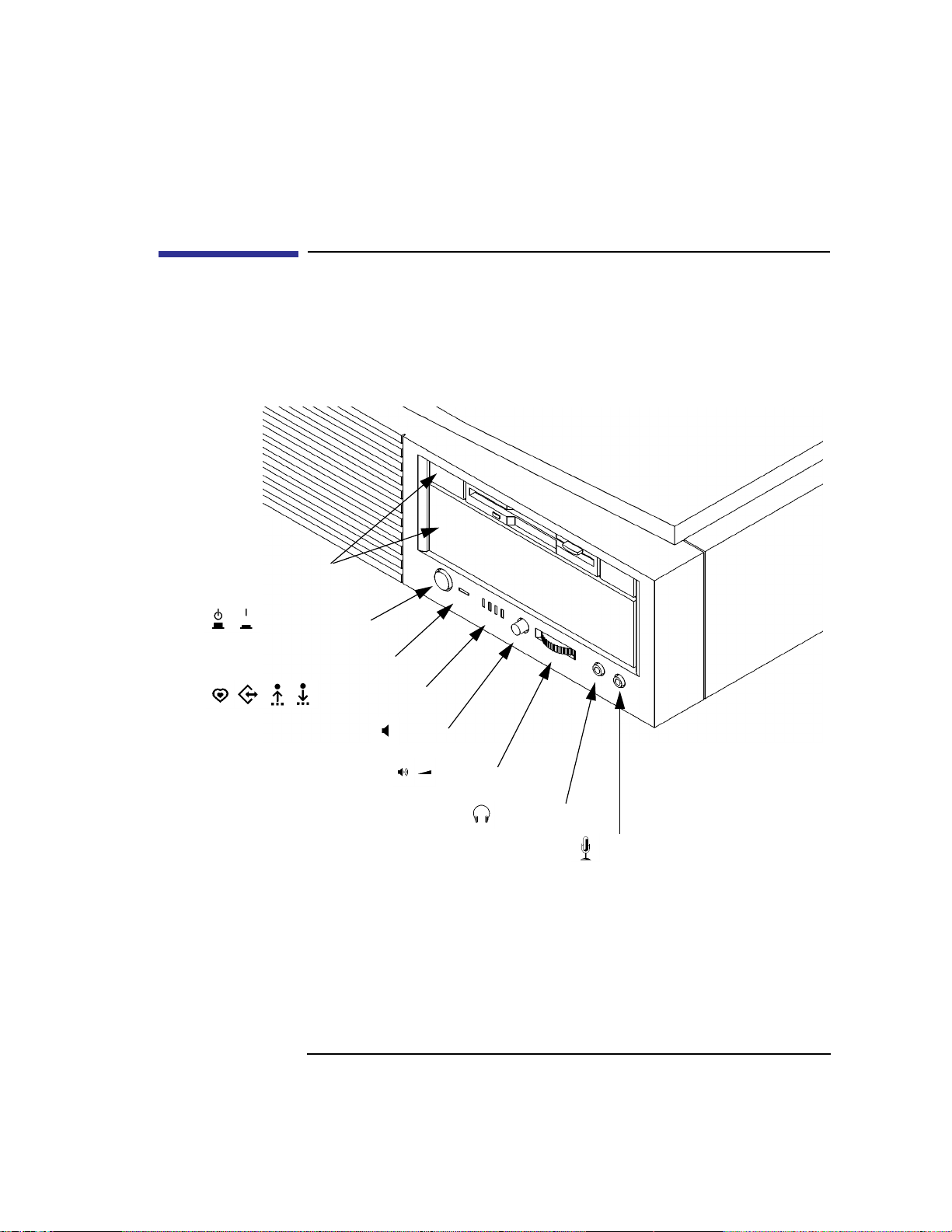
System Unit Front Panel Controls and LEDs
Before powering on your system, you should become familiar with the
system unit controls.
Figure 1 shows the system unit front panel controls.
Removable
Storage Devices
Power Switch
System Overview
System Unit Front Panel Controls and LEDs
Power LED
System LEDs
Mute
Volume
Headset
Figure 1 System Unit Front Panel Controls
Mic
11
Page 26

System Overview
System Unit Front Panel Controls and LEDs
System Power Switch
Use the Power switch to power the system unit on and off.
NOTICE: There is no need to manually shut down the HP-UX operating system on
your workstation before powering it off. When you turn off the power
switch, your workstation automatically shuts down the operating system
before terminating the power.
Power LED
The Power LED lights when the system unit power is on.
System LEDs
The system LEDs indicate the status of your workstation. In the event of a
system problem, the LEDs are lighted in different patterns to indicate error
codes. See Chapter 6 for a complete list of the system LED error codes.
12
LED 4 - System Heartbeat
LED 3 - SCSI Bus Activity
LED 2 - Network Receive
LED 1 - Network Transmit
Page 27

System Overview
System Unit Front Panel Controls and LEDs
Audio Controls
Next to the system LEDs are the following audio controls:
Headset Jack Accommodates mini-headphones with a 3.5-mm diame-
ter miniature stereo plug.
Volume Control Adjusts the audio output volume to the headset jack or
line out.
Mic Jack Accommodates microphones with a 3.5-mm diameter
miniature stereo plug.
Mute Button Turns off the audio output to line out and speaker only.
NOTICE: The Volume Control, Headphone Jack, and Mic (microphone) Jack features
of the CD-ROM are supported through software applications only.
For more information on the features and electrical specifications, see
“Audio Connectors” later in this chapter.
Removable Storage Devices
The Models B132L/B132L+/B160L/B180L support the following removable
storage devices:
• CD-ROM Disc Drive
• DDS-Format Tape Drive
• Floppy Diskette Drive
NOTICE: Due to space limitations, a DDS-format tape drive and a CD-ROM drive
cannot both be mounted in the system at the same time. Also, adding either
a DDS tape or CD-ROM takes on internal drive bay, leaving only one
internal drive bay available for a hard disk drive.
A description of each drive’s controls and indicators is in the chapter
describing that device, later in this book.
13
Page 28
System Overview
System Unit Rear Panel Connectors
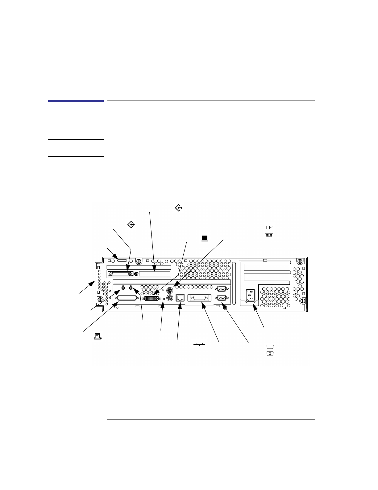
System Unit Rear Panel Connectors
This section describes the connectors on the system unit’s rear panel
NOTICE: To maintain electro-magnetic and radio frequency emissions compliance,
verify that all cables are fully seated and properly fastened.
Figure 2 shows the locations of the connectors on the system unit’s rear
panel.
Fast, Wide or Ultra, Wide SCSI
Single-Ended SCSI
Security Loop
Pullout Card
Audio Line In
HP Parallel
Audio Line Out
TOC
Monitor
PS/2 Mouse
PS/2 Keyboard
LAN-AUILAN-TP
Power
Serial 1
Serial 2
Figure 2 System Unit Rear Panel Connectors
14
Page 29

System Overview
System Unit Rear Panel Connectors
Security Loop
The security loop provides a means of locking the storage tray, with a padlock or other locking device, to prevent unauthorized removal from the system.
Audio Connectors
Your workstation has audio input and output capability through external
input and output connectors on the rear panel and through an internal
speaker. The rear panel contains the Audio IN (stereo line-in) and Audio
OUT (stereo line-out) connectors.
NOTICE: To maintain compliance with FCC/CISPR B you must use fully shielded,
unbalanced audio cables and plugs.
The audio connectors are standard stereo audio mini-jacks. Hewlett-Packard
recommends using gold-plated plugs available through audio retailers for
best quality recording and playback through the external connectors. The
following is a summary of the workstation audio features:
• Audio Features
• Audio Input
Programmable sample rates:
8kHz, 16kHz, 32kHz, 48kHz, 11.025kHz,
22.05kHz, and 44.1kHz.
Programmable output attenuation:
0 to -96dB in -1.5dB steps
Programmable input gain:
0 to 22.5dB in 1.5dB steps
Input monitoring:
16-bit linear, 8-bit u-law, or A-law coding
Line In
Mono microphone (on the front panel) compatible with
1.5V phantom supply (bias voltage supplied by the
15
Page 30

System Overview
System Unit Rear Panel Connectors
system).
CD-ROM audio (if internal CD-ROM is installed)
• Audio Output
Line-out
Headphone (on the front panel)
Built-in mono speaker
• Audio CODEC
Crystal CS4215
The audio electrical specification for this workstation are summarized in
Table 1
Table 1 Audio Electrical Specifications
Frequency Response
Input Sensitivity/Impedance
Line In 2.0Vpk/47k ohm
Microphone 22mVpk/1k ohm
Max Output Level/Impedance
Line Out 2.8Vpp/47k ohm
Headphone 2.75Vpp/50 ohm
Speaker (internal) 5.88Vpp/48 ohm
Output Impedance
Line Out 619 ohm
Headphone 118 ohm
Signal to Noise*
Line Out 65 dB
Headphone 61 dB
Speaker 63 dB
Line In 61 dB
Microphone 57 dB
THD (w nominal load)
Line Out -73 dB
Headphone -70 dB
Speaker -68 dB
Line In -75 dB
25-20,000 Hz
16
Page 31

Table 1 Audio Electrical Specifications
Microphone -73 dB
*To convert from dB to number of significant bits, use the formula:
dB
---------------------------
n
=
20 10log[]
For example, for 61dB S/N then n=61/6 or approx. 10 significant bits, or in other
words, about 6 bits of noise.
Keyboard Connectors
PS/2 Keyboard and Mouse Connectors
The PS/2 connectors provide an interface for a keyboard and a mouse to the
system. Consult the documentation that accompanies each input device for
specific information concerning its use.
HP Parallel I/O Connector
System Overview
System Unit Rear Panel Connectors
dB
------ -
≈
6
The 25-pin HP Parallel I/O interface uses Centronics interface protocols to
support peripheral devices such as printers and plotters. Consult the documentation that accompanies each peripheral device for specific information
concerning its use.
802.3 Network Connectors
Your workstation has built-in LAN-AUI and LAN-TP (Twisted Pair) connectors for the 802.3 (ETHERNET) network. Connections to ThinLAN networks require an external transceiver. Your workstation will autoselect the
correct network setting. The Models
ally select your LAN configuration.
NOTE: Only one of the network connectors can be used at one time.
B132L+/B180L allow you to also manu-
17
Page 32

System Overview
System Unit Rear Panel Connectors
Serial I/O Connectors
You can attach a variety of pointing devices (such as a mouse or trackball),
or peripheral devices to the Serial Input/Output (SIO) ports on the B132L/
B132L+/B160L/B180L workstation. Peripheral devices include printers,
plotters, modems, and scanners. Consult the documentation that accompanies each pointing or peripheral device for specific information concerning
its use.
The SIO ports are programmable. You can set functions such as bit rate,
character length, parity , and stop bits. The SIO ports are used as an interface
for serial asynchronous devices to the CPU. The ports operate at up to a
460.8K baud rate.
T able 2 shows the SIO connector pin listings. The serial connectors are 9-pin
D-sub connectors. Signal names are those specified in the EIA RS-232 standard.
Table 2 Serial I/O Pins
Pin No. Signal Description
1 DCD Data Carrier Detect
2 RXD Receive Data
3 TXD Transmit Data
4 DTR Data Terminal Ready
5 GND Ground
6 DSR Data Set Ready
7 RTS Request To Send
8 CTS Clear To Send
9 RI Ring Indicator
SCSI Connectors
Use the narrow single-ended SCSI, and fast, wide differential SCSI, or ultra
wide, single-ended SCSI connectors to connect external SCSI devices such
as DDS-format tape drives, disk drives and CD-ROM drives. Consult the
18
Page 33

System Overview
System Unit Rear Panel Connectors
documentation that accompanies each SCSI device for specific information
concerning its use. Refer to Appendix C for information about connecting
SCSI devices to your workstation.
NOTICE: When attaching external SCSI devices, be sure to terminate the last device
on the external SCSI bus with the appropriate terminator. If there are no
external SCSI devices, attach a SCSI terminator to the back of the system.
TOC Button
The TOC (transfer of control) button resets the system and transfers control
from the default device to an auxiliary device.
Power Cord Connector
Plug the workstation’s power cord into the power cord connector to provide
ac power to the system.
19
Page 34

System Overview
Monitors
Monitors
You can use one of the following HP monitors with your workstation:
• 17-inch, 1280x1024 color monitor (A4330)
• 20-inch, 1280x1024 color monitor (A4331)
Before using your monitor you should become familiar with its controls,
connectors, and indicators. For this information, consult the documentation
that was packaged with your monitor.
The built-in monitor connector is an Enhanced V ideo Connector . An EVC to
DB adapter (HP Part Number 8120-6861) is required to use older monitor
types.
Keyboard
The B132L/B132L+/B160L/B180L uses a PS/2 keyboard which connects to
the PS/2 interface connector on the rear of your workstation.
Pointing Devices
You can use an HP three-button mouse, a trackball, or other options as pointing devices using the PS/2 connector or the Serial ports. For instructions on
using your particular pointing device, see the manual that came with it.
For general information on using three-button mice and on the various cursor shapes associated with different areas of HP VUE or CDE while using a
mouse, see Using Your HP Workstation.
20
Page 35

System Overview
Operating System Overview
Operating System Overview
Your B132L/B160L workstation uses the HP-UX operating system, version
10.2 or greater. Your
system, version 10.2 or greater with Additional Core Enhancements (ACE).
Instant Ignition systems, (systems with preloaded software), have X-windows and Hewlett-Packard’s graphical user interface, HP VUE version 3.0,
installed and configured.
Please refer to the “Instant Ignition System Configuration Information”
sheet that shipped with your system for details on configuration.
If you have any questions about Instant Ignition, refer to Using Your HP
Workstation for more information.
NOTICE: When you power on your workstation, a selftest is performed before the
system boots.
B132L+/B180L workstation uses the HP-UX operating
21
Page 36

System Overview
Important Information You Need to Record
Important Information You Need to Record
Before you begin using your workstation, take a moment to gather the following important information and note it in the appropriate subsection for
future use:
• LANIC ID
• SCSI device ID(s)
• Device file used for each SCSI device
• Internet Protocol (IP) address
• Subnetwork mask
NOTICE: For help with these, refer to Using your HP Workstation.
LANIC ID
Locate the contents label that comes with the workstation shipping carton.
Find the LANIC ID listed there and write it down in the space provided:
LANIC ID ____________________________________________
You can also get your LANIC ID by using the lanscan command in a termi-
nal window. To do this, follow these steps:
1 Turn your workstation and monitor on, if you have not already done so. Figure 1
of this chapter shows the location of the power switch on the workstation. See the
documentation that came with your monitor for the location of the monitor power
switch. Boot the HP-UX operating system.
2 In a terminal window, enter the following at the prompt:
/usr/sbin/lanscan
You will see a table similar to Table 3.
22
Page 37

Table 3 Sample LANSCAN COMMAND TABLE
Hardware Station Dev Hardware Net-Interface NetMgt Encapsulation
Path Address lu State Name Unit State ID Methods
2.0.2 0x0800091595EE 0 UP lan0 UP 4 ETHER IEEE8023
The LANIC ID in this example is 0800091595EE.
You may also obtain the system’s LANIC ID from the information menu in
the Boot Console Handler. For detailed information see Appendix D.
IP Address and Subnetwork Mask Information
Get the IP address and the subnet mask information for your workstation
from either your System Administrator or your Network Administrator and
note them here:
System Overview
Important Information You Need to Record
IP address ____________________________________________________
subnet mask __________________________________________________
23
Page 38

System Overview
Networking Overview
Networking Overview
Your workstation is capable of many more tasks than are described in this
owner’s guide. This section gives an overview of some of the networking
capabilities of your system and directs you to the appropriate source for
more information.
Mail
Electronic mail allows you to send and receive mail messages on your workstation. For information on setting up and using electronic mail on your
workstation, contact your system administrator and also see the Using Your
HP Workstation manual that came with your workstation.
telnet
The telnet application uses the TELNET protocol to communicate with
another computer system on the network. The telnet application allows you
to log on to the remote system from your workstation. If your system has
man pages installed, you may read the online telnet man page by entering
the following at a command-line prompt:
man telnet
rlogin
The rlogin application also allows you to log on to another computer system
on the network from your workstation. For more information on rlogin, see
the Using Your HP W orkstation manual that came with your workstation and
read the online man page by entering the following at a command-line
prompt:
24
Page 39

System Overview
Networking Overview
man rlogin
ftp
The ftp application is a user interface to the File Transfer Protocol. Use ftp to
copy files between your workstation and another computer system on the
network. For more information, see the Using Your HP Workstation manual
that came with your workstation and read the online man page by entering
the following at a command-line prompt:
man ftp
rcp
The rcp application allows you to remotely copy files from another computer
system on a network to your workstation. For more information, see the
Using Your HP Workstation manual that came with your workstation and
read the online man page by entering the following at a command-line
prompt:
man rcp
NFS
The Network File System (NFS) allows your workstation to access files on
remote computer systems as if they were on your local system. The file system on the remote computer system does not have to be compatible with
your workstation’s file system. For more information, see Installing and
Administering NFS Servers and HP-UX System Administration Tasks manuals.
25
Page 40

System Overview
Networking Overview
26
Page 41

2
Using Your CD-ROM Drive
27
Page 42

Using Your CD-ROM Drive
This chapter describes how to use your CD-ROM drive. It is divided into the
following sections:
• CD-ROM drive and CD-ROM media descriptions
• Operating the CD-ROM Drive
• Mounting and unmounting a CD-ROM disc
• Troubleshooting
NOTICE Be sure you read and understand the information on mounting and
unmounting CD-ROM discs before you begin using your CD-ROM disc
drive.
This chapter provides an overview of the optional CD-ROM drive and
media, and describes how to use the CD-ROM drive. We assume the CDROM drive is set to the factory default address of SCSI ID 2.
NOTICE Some procedures in this chapter require you to log in as root. If you cannot
log in as root, contact your system administrator.
28
Page 43

Using Your CD-ROM Drive
CD-ROM Drive and CD-ROM Media Descriptions
CD-ROM Drive and CD-ROM Media Descriptions
This section describes basic information needed for using the CD-ROM
drive and CD-ROM discs.
CD-ROM Drive
The CD-ROM drive is a random access read-only mass storage device that
uses removable CD-ROM discs. The drive supports the ISO 9660 and High
Sierra format standards. You can access information from the drive like any
other disk drive, except that you cannot write to the drive. The drive contains
a semiconductor laser for reading data optically, and includes an embedded
controller with a SCSI interface.
29
Page 44

Using Your CD-ROM Drive
CD-ROM Drive and CD-ROM Media Descriptions
Controls and Features
Figure 3 shows and Table 4 describes the operating controls and features of
the CD-ROM drives.
Headset
Jack
Figure 3 CD-ROM Drive Controls and Features
Volume
Control
Thumbwheel
Indicator
Busy
Emergency
Eject Hole
Eject
Button
30
Page 45
CD-ROM Drive and CD-ROM Media Descriptions
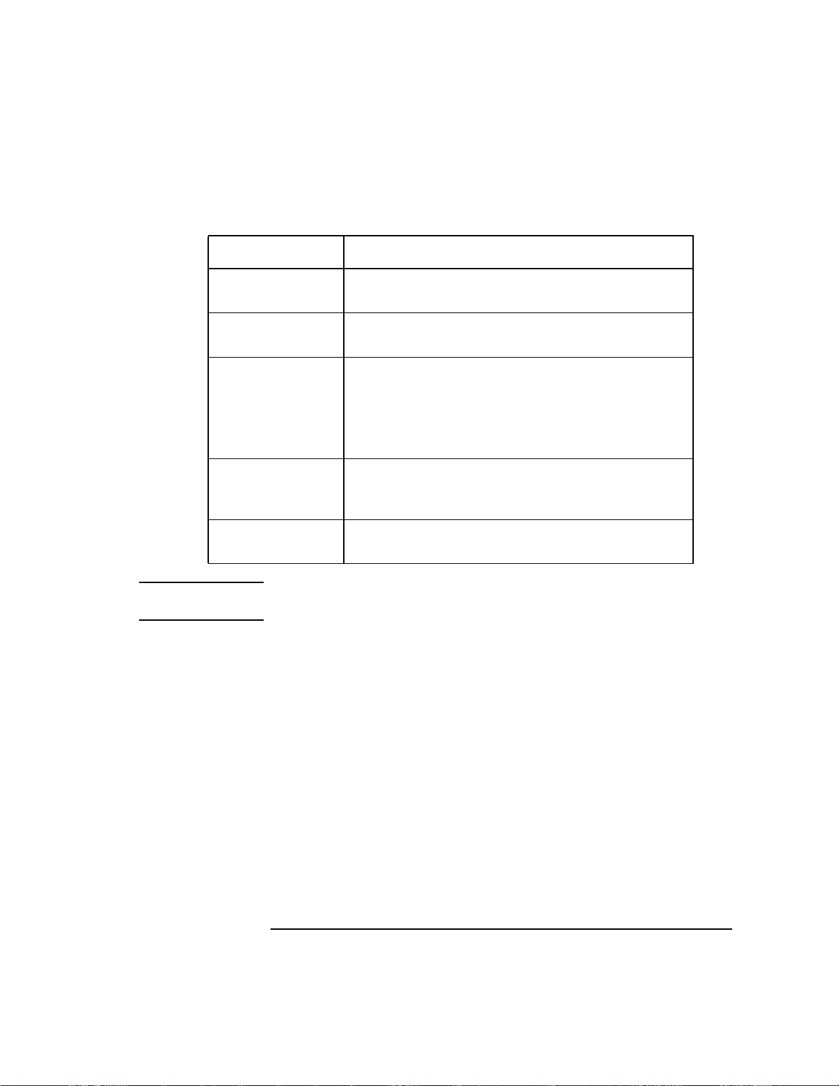
Table 4 CD-ROM Drive Operating Controls and Features
Control/Feature Purpose
Headset Jack You can plug mini-headphones with a 3.5-mm diameter
miniature stereo plug into this jack.
Volume Control Use the volume control to adjust the audio output volume to
the headset jack.
Busy Indicator The Busy Indicator lights during a data access operation and
blinks during a data transfer. The indicator blinks initially
and then stays lit when there is one of the following:
• A defective disc
• A disc insertion error (for example, an upside-down disc)
Eject Button Press the Eject Button to open the Disc Tray and insert or
remove a disc. When the drive is in use, you must press the
eject button for more than one second to open the Disc Tray.
Emergency Eject By inserting the end of a paper clip you can open the Disc
Tray when the workstation does not have power.
Using Your CD-ROM Drive
NOTICE The Volume Control, Headset Jack, and Audio Jack features of the CD-
ROM drive are supported through applications only.
31
Page 46

Using Your CD-ROM Drive
CD-ROM Drive and CD-ROM Media Descriptions
CD-ROM Media
CD-ROM discs are 120 mm (4.7 in.) in diameter, and use one data surface
with a capacity of approximately 600 megabytes. The data surface contains
pits and flat spots arranged in a continuous spiral track, which is read at a
constant speed. You may access files and data stored on a CD-ROM disc, but
you may not write files or data to a CD-ROM disc.
CD-ROM data discs are identical to audio compact discs (CDs) except that
they store computer data and information.
CAUTION: Handle CD-ROM discs by the edges only. Always be sure a CD-ROM disc is either
in the CD-ROM drive or its protective case when not in use. This will lessen the
chance of exposing the disc surface to dust. Over time, dust reduces the reliability of
the read head in the CD-ROM drive.
Caring for CD-ROM Discs
Observe the following guidelines to help prevent data loss and prolong the
life of your CD-ROM discs and drive:
• Use CD-ROM discs in a clean environment to prevent dust particles from
scratching disc surfaces.
• Store CD-ROM discs in a cool, dry place to prevent moisture and heat
damage.
• Don’t try to clean the surface of a CD-ROM disc with cleaning solvents,
as some cleaning solvents may damage the disc.
NOTICE: You must mount the disc after loading it into the drive. Refer to the section
“Mounting and Unmounting a CD-ROM Disc,” later in this chapter, for
instructions about mounting a disc.
32
Page 47
Using Your CD-ROM Drive
Operating the CD-ROM Drive
Operating the CD-ROM Drive
This section describes how to perform tasks with your CD-ROM drive.
Loading and Unloading a CD-ROM in the Disc Tray
This subsection describes how to load or unload a CD-ROM disc in the CDROM drive.
Disc Tray Description
This CD-ROM is designed to be used in either the horizontal or vertical
position, depending on whether your system unit is horizontal or vertical (in
the floor stand). The disc tray has four spring-loaded disc holders that hold
the disc in place when the CD-ROM drive is in the vertical position. When
the drive is in the horizontal position, the disc holders are not used and are
held out of the way by four disc holder retainers. Figure 4 shows the CDROM disc tray, and disc holders.
Disc
Holder
Figure 4 CD-ROM Disc Tray
Disc
Holder
Disc
Holder
33
Page 48

Using Your CD-ROM Drive
Operating the CD-ROM Drive
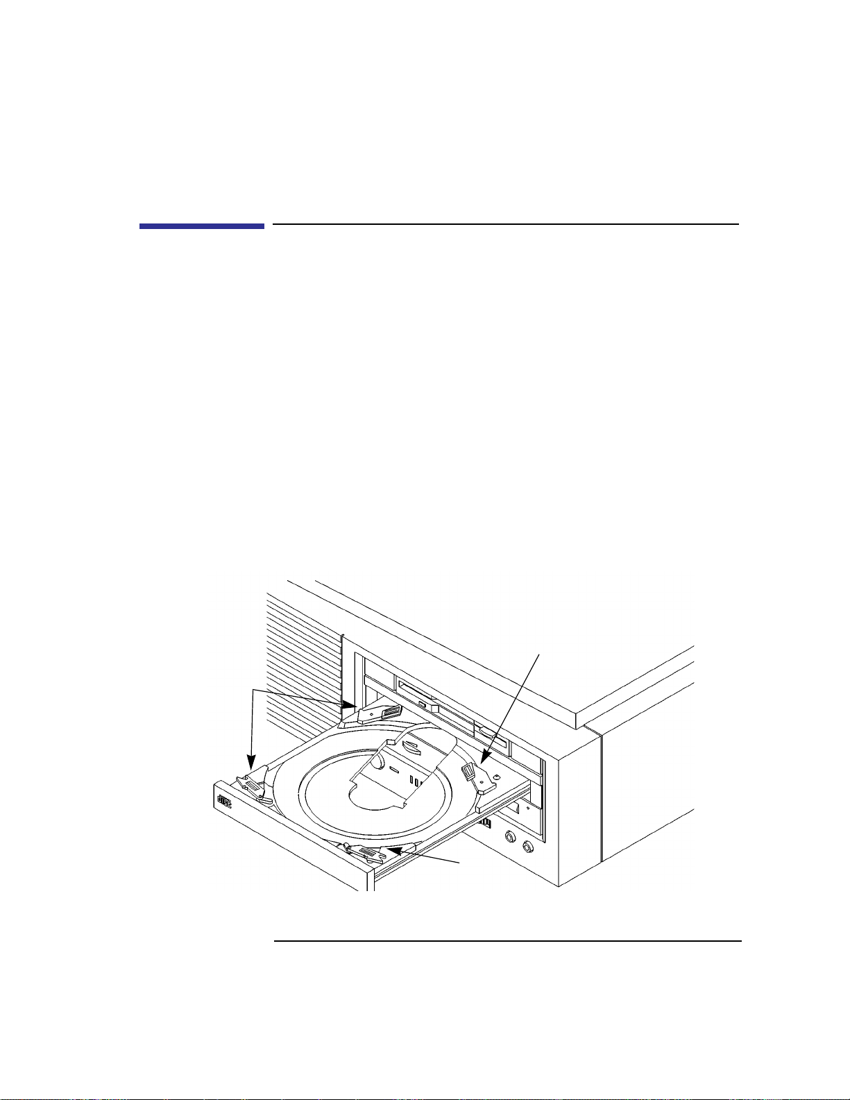
Loading a CD-ROM Disc in a Horizontally Mounted Drive
This CD-ROM drive has an automatic loading/ejecting feature. To load a
disc in the CD-ROM drive, follow these steps:
Figure 5 Placing a CD-ROM Disc in a Horizontally Mounted Drive
1 Check that the workstation is powered on.
2 To open the disc tray, press and release the load/eject button on the CD-ROM
drive.
3 Be sure the disc holders are held away from the disc by the disc holder retainers.
4 Hold the disc by the edges with the label side up and place it in the disc tray as
shown in Figure 5.
5 To close the disc tray, push the front of the disc tray gently towards the drive until
it closes by itself.
34
Page 49

Using Your CD-ROM Drive
Operating the CD-ROM Drive
Unloading a CD-ROM Disc in a Horizontally Mounted Drive
Perform the following steps to unload a disc from the CD-ROM drive:
Figure 6 Removing a CD-ROM Disc From a Horizontally Mounted Drive
1 Press the eject button to eject the disc tray from the drive. If the drive is in use,
you must press the eject button for more than one second to eject the disc tray.
NOTICE: You must unmount the disc before eject it from the drive. Refer to the
subsection, “Unmounting a CD-ROM Disc Using SAM,” for instructions
on unmounting a disc.
2 Wait until the drive has fully ejected the disc tray. Be sure the disc holders are
held away from the disc by the disc holder retainers, Then remove the disc from
the tray as shown in Figure 6. Be careful to touch only the edges of the disc.
3 To close the Disc Tray, push the front of the disc tray gently towards the drive
until it closes by itself.
35
Page 50
Using Your CD-ROM Drive
Operating the CD-ROM Drive
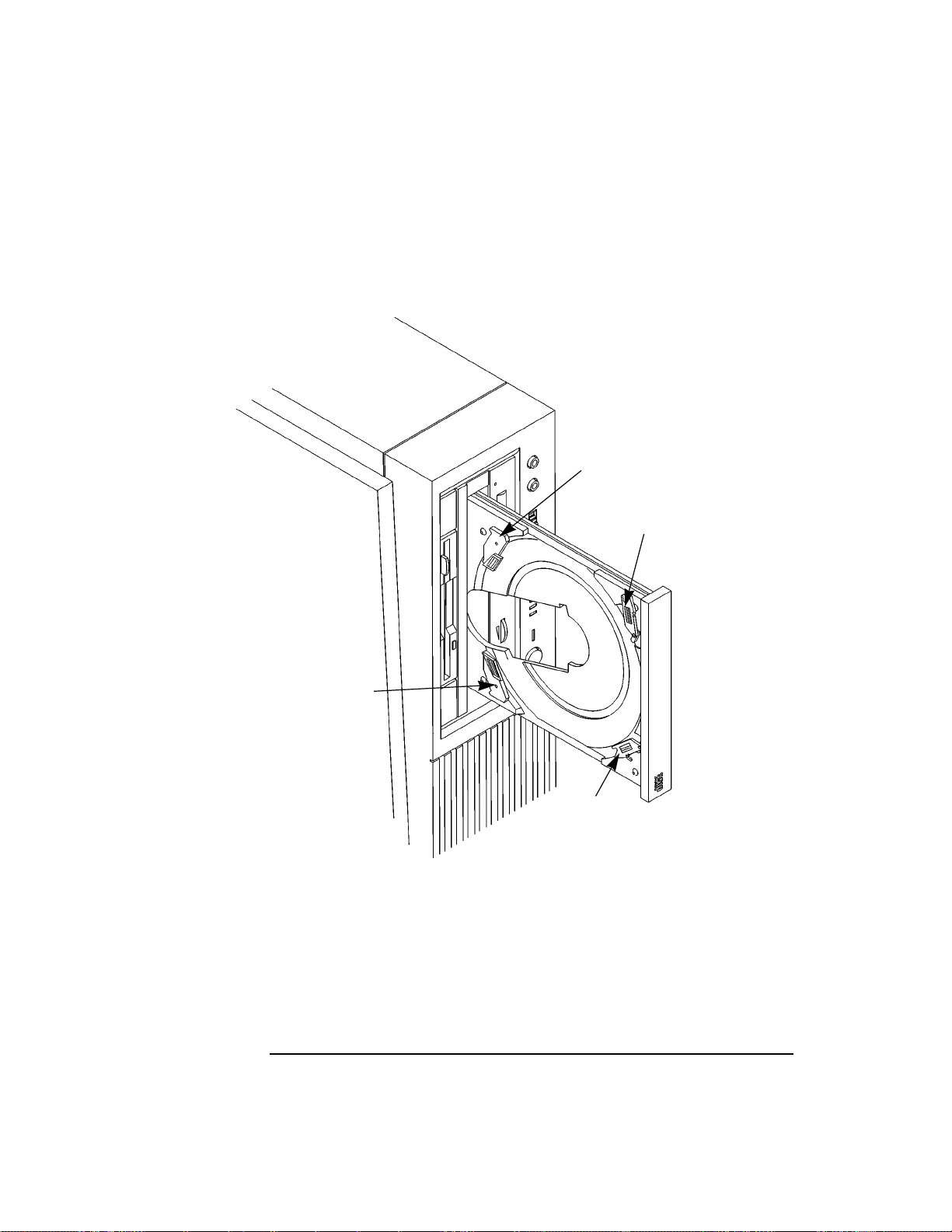
Loading a CD-ROM Disc in a Vertically Mounted Drive
To load a disc in the CD-ROM drive, follow these steps:
Disc
Holder D
Disc
Holder C
Disc
Holder A
Figure 7 Releasing the Disc Holder Retainers
1 Make sure the three disc holders are disengaged from the disc holder retainers, as
shown in Figure 7.
36
Disc
Holder B
Page 51

Using Your CD-ROM Drive
Operating the CD-ROM Drive
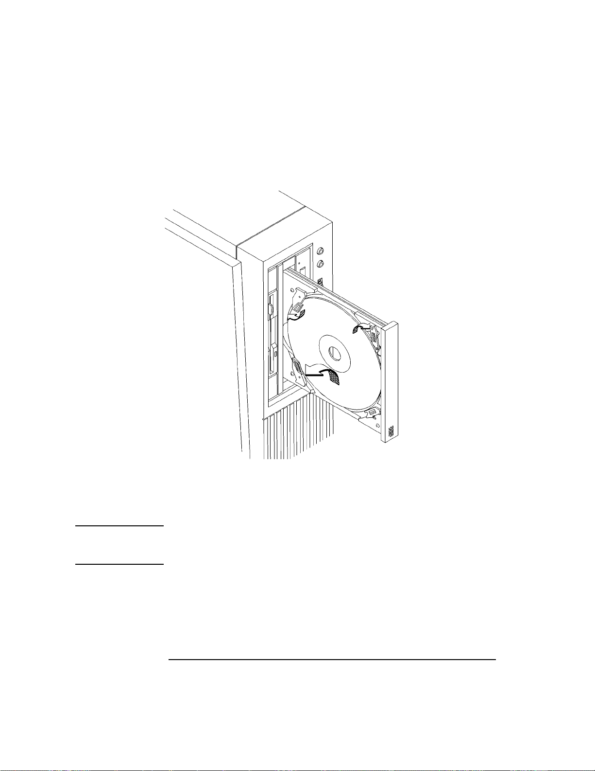
2 Hold the disc with the label side away from the tray and place the edge of the disc
onto disc holders A and B as shown in Figure 8.
Figure 8 Placing a CD-ROM Disc in a Vertically Mounted Drive
3 Press down gently against the spring tension of disc holders A and B, and swing
the top of the disc in until it is held by disc holders C and D.
4 To close the disc tray, push the front of the disc tray gently towards the drive until
it closes by itself.
37
Page 52
Using Your CD-ROM Drive
Operating the CD-ROM Drive
Unloading a CD-ROM Disc in a Vertically Mounted Drive
Perform the following steps to unload a disc from the CD-ROM drive:
Figure 9 Removing a CD-ROM Disc From a Vertically Mounted Drive
1 Press the eject button to eject the disc tray from the drive. If the drive is in use,
you must press the eject button for more than one second to eject the disc tray.
NOTICE: You must unmount the disc before eject it from the drive. Refer to the
subsection, “Unmounting a CD-ROM Disc Using SAM,” for instruction on
unmounting a disc.
2 Press down gently against the spring tension of disc holders A and B and swing
the top of the disc away from disc holders C and D as shown in Figure 9.
3 Remove the disc from disc holders A and B.
4 To close the Disc Tray, push the front of the disc tray gently towards the drive
until it closes by itself.
38
Page 53

Using Your CD-ROM Drive
Operating the CD-ROM Drive
Verifying the CD-ROM Drive Operation
To verify that your workstation can communicate with the CD-ROM drive,
follow these steps:
1 In a terminal window, enter the following command:
/usr/sbin/ioscan -d sdisk RETURN
After a few moments the ioscan utility lists all of the SCSI I/O devices it could
find. The list appears similar to the following:
H/W Path Class Description
============================================
bc
8 bc I/O Adapter
8/12 ext_bus GSC built-in Fast/Wide SCSI Interface
8/12.0 target
8/12.0.0 disk QUANTUM LPS1080WD
8/12.5 target
8/12.5.0 disk DEC DSP3210SW
8/12.6 target
8/12.6.0 disk DEC DSP3210SW
8/16 ba Core I/O Adapter
8/16/5 ext_bus Built-in SCSI
8/16/5.2 target
8/16/5.2.0 disk TOSHIBA CD-ROM XM-4101TA
8/16/5.4 target
8/16/5.4.0 disk SEAGATE ST3600N
8/16/5.6 target
8/16/5.6.0 disk MICROP 2112
10 bc I/O Adapter
10/12 ext_bus GSC add-on Fast/Wide SCSI Interface
10/12.4 target
10/12.4.0 disk SEAGATE ST31200W
If ioscan does not see your CD-ROM drive it returns the following message:
ioscan: No hardware found
If you receive this message, go to Chapter 6, “Solving Problems.”
39
Page 54

Using Your CD-ROM Drive
Mounting and Unmounting a CD-ROM Disc
Mounting and Unmounting a CD-ROM Disc
To access information on a CD-ROM disc, you must first mount the disc.
This applies to file system information only . If you wish to load a music CD,
for example, you would not need to mount the disc. Mounting a disc with
file system information on it gives the disc a pathname that allows your
workstation to communicate electronically with it. You must unmount the
CD-ROM disc before removing it from the drive.
CAUTION: T o use a CD-ROM disc as a mounted file system, you must mount the CD-ROM disc
every time you load it into the drive. You must also unmount the CD-ROM disc
every time you unload it from the drive. Failure to mount or unmount a disc can cause
a system error condition that can require rebooting the system.
If your workstation is running HP VUE, follow these instructions to mount
and unmount a CD-ROM disc as a file system. If you’re using something
other than HP VUE, use the instructions for mounting and unmounting a
CD-ROM disc that come with that product. For more information on configuring your CD-ROM drive, see the System Administration Tasks manual or
online help.
The procedures in this chapter require you to log in as root. If you cannot
log in as root, contact your system administrator.
Mounting a CD-ROM Disc Using SAM
Use the following procedure to mount a CD-ROM disc:
1 Log in as root. If you need information on logging in or setting up a user
account, see Using Your HP Workstation.
2 Load the CD-ROM disc into the disc tray and gently push the tray into the
drive.
3 In a terminal window, enter the following command:
sam RETURN
40
Page 55

Using Your CD-ROM Drive
Mounting and Unmounting a CD-ROM Disc
4 The System Administration Manager window opens. Double-click on
Peripheral Devices ->.
5 The Peripheral Devices window opens. Double-click on Disks and File
Systems ->.
6 The Disks and File Systems window opens. Double-click on CD-ROM,
Floppy, and Hard Disks.
The following screen message appears:
Scanning the system’s hardware...
The CD-ROM, Floppy, and Hard Disks window opens containing a list of
drives currently configured on this system. Disks that are unmounted will have
the word “unused” in the Use column.
7 From the Actions menu, click on Add a Hard Disk Drive
8 The Select a Disk to Add... window opens with a list of unused disks. Highlight
the CD-ROM disc you want to mount.
9 Click on OK.
10 The Set Disk Usage and Options... window opens. Select File System
and click on
OK.
11 The following screen messages appear:
Task started.
Creating the device file...
Mounting file system...
Modifying “/etc/checklist”...
Task completed.
Click on OK.
Now you can access the CD-ROM disc as you would any other mounted file
system.
41
Page 56

Using Your CD-ROM Drive
Mounting and Unmounting a CD-ROM Disc
Unmounting a CD-ROM Disc Using SAM
Use the following procedure to unmount a CD-ROM disc:
NOTICE: Before you unmount a CD-ROM disc, make sure that your working
directory (the directory in which a relative path name search begins)
is set to some directory other than the one under which the disc was
mounted.
CAUTION: If you wish to use a CD-ROM disc as a mounted file system, you must mount
the CD-ROM disc every time you load it into the drive. You must also
unmount the CD-ROM disc every time you unload it from the drive. Failure
to mount or unmount a disc may cause a system error condition that may
require rebooting the system.
1 Log in as root. If you need information on logging in or setting up a user
account, see Using Your HP Workstation.
2 In a terminal window, enter the following command:
sam RETURN
3 The System Administration Manager window opens. Double-click on
Peripheral Devices ->.
4 The Peripheral Devices window opens. Double-click on Disks and File
Systems ->.
5 The Disks and File Systems window opens. Double-click on CD-ROM,
Floppy, and Hard Disks.
The following screen message appears:
Scanning the system’s hardware...
The CD-ROM, Floppy, and Hard Disks window opens containing a list of
drives currently configured on this system.
6 Highlight the disc you want to unmount and click on Remove a Hard
Disk Drive from the Actions menu.
42
Page 57

Using Your CD-ROM Drive
Mounting and Unmounting a CD-ROM Disc
7 A window with the following message opens:
Do you want to remove the disk?
Click on Yes.
8 Press the eject button on the CD-ROM drive and remove the CD-ROM
disc from the disc tray.
Reading the Busy Light
The CD-ROM busy light shows the status of the drive during the self test
and during activity with the host system.
The CD-ROM drive performs the self test when one of the following happens:
• You load a disc and close the Disc Tray.
• You turn on the workstation with a disc already loaded in the CD-ROM
drive.
For the self test, the busy light operates in the following sequence:
1 Light On - The busy light goes on when the disc loads into the
drive.
2 Light Flashing - The light flashes six times while a read test is per-
formed on the disc.
3 Light Off - The light goes off when the self test is complete.
43
Page 58

Using Your CD-ROM Drive
Mounting and Unmounting a CD-ROM Disc
The busy light stays on after the self test when one of the following conditions exist:
• A defective disc.
• A disc insertion error (for example, an upside-down disc).
The busy light goes off when one of the following conditions exist:
• A CD-ROM drive power failure exists.
• The drive is idle on the SCSI bus.
The busy light flashes during normal activity with the system.
44
Page 59

Using Your CD-ROM Drive
Troubleshooting
Troubleshooting
If you have trouble with any of these procedures for using your CD-ROM
drive, see Chapter 6 of this book, “Solving Problems.”
45
Page 60

Using Your CD-ROM Drive
Troubleshooting
46
Page 61

3
Using Your Digital Data Storage (DDS)
Tape Drive
47
Page 62

Using Your Digital Data Storage (DDS) Tape Drive
This chapter describes how to use the optional Digital Data Storage (DDS)
tape drive. It also describes how to maintain and care for the drive.
This chapter provides information on the following:
• DDS tape drive and data cassette descriptions
• Operating the DDS tape drive
• Ordering information
CAUTION: Use only data cassettes labeled DDS (Digital Data Storage). Never use audio
cassettes labeled DAT (Digital Audio Tape) in your DDS-format drive.
48
Page 63

Using Your Digital Data Storage (DDS) Tape Drive
DDS Tape Drive and Data Cassette Descriptions
DDS Tape Drive and Data Cassette Descriptions
This section describes basic information needed for using your DDS tape
drive and data cassettes.
DDS Drive
Your DDS tape drive is either a DDS-DC (early or later model) or a DDS-2
tape drive with a 3.5-inch form factor, data compression, and a single-ended
SCSI interface. Both drives incorporate data compression capability and are
high-capacity, high transfer-rate devices for data storage on tape. With compression, the DDS-DC drives can store up to 4 GB of data on a 90 meter tape
and the DDS-2 drive can store up to 8 GB of data on a 120 meter tape.
Storage Capacities
The maximum storage capacities of different DDS drives with and without
data compression are shown in the following tables;
Table 5 DDS Tape Drive Capacities Without Data Compression
Tape Length
60 meter 1.3 GB 1.3 GB 1.3 GB
90 meter Not Supported 2.0 GB 2.0 GB
120 meter Not Supported Not Supported 4.0 GB
Table 6 DDS Tape Drive Capacities With Data Compression
Tape Length
60 meter 2.6 GB 2.6 GB 2.6 GB
90 meter Not Supported 4.0 GB 4.0 GB
120 meter Not Supported Not Supported 8.0 GB
Full Height 5 1/4
DDS Tape Drive
Full Height 5 1/4
DDS Tape Drive
DDS-DC
Tape Drives
DDS-DC
Tape Drives
DDS-2
Tape Drive
DDS-2
Tape Drive
49
Page 64
Using Your Digital Data Storage (DDS) Tape Drive
DDS Tape Drive and Data Cassette Descriptions
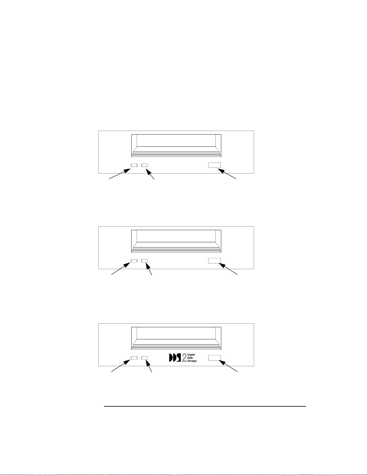
Controls and Indicators
Figure 10, Figure 11, and Figure 12 show the LEDs, and eject button of the
DDS-format tape drives.
Cassette LED Drive LED Eject Button
Figure 10 DDS-DC (Early Model) Drive Controls and Indicators
Tape Clean
DCLZ
Tape LED Clean/Attention LED Eject Button
Figure 11 DDS-DC (Later Model) Drive Controls and Indicators
Tape Clean
Tape LED Clean/Attention LED Eject Button
Figure 12 DDS-2 Drive Controls and Indicators
50
Page 65

Using Your Digital Data Storage (DDS) Tape Drive
DDS Tape Drive and Data Cassette Descriptions
LEDs
This section describes the LED codes that are displayed.
The two LEDs on the front panels of the DDS drives indicate different activ-
ities or problems that occur.
Figure 13 lists the LED codes and their meanings for the DDS-DC early
model drive. Figure 14 lists the LED codes and their meanings for the DDSDC later model and DDS-2 drives.
Cassette Drive Meaning
Read/Write States
Cassette (un)loading
Cassette loaded/online
Cassette loaded/activity
Cassette loaded/offline
Write-Protect States
Cassette (un)loading
Cassette loaded/online
Cassette loaded/activity
Cassette loaded/offline
Error States
Media wear (caution)
High humidity
Self-test (normal)
Key
OFF
Green
Amber
Pulsing Green
Pulsing Amber
Pulsing Green
and Amber
Self-test (failure)
Figure 13 DDS-DC (Early Model) Tape Drive LED Display Codes
51
Page 66

Using Your Digital Data Storage (DDS) Tape Drive
DDS Tape Drive and Data Cassette Descriptions
Tape Clean/ Meaning
Any
Attention
Activity — load or unload
Activity — read or write
Cartridge loaded
Cleaning needed
FaultAny
Key
OFF
Steady Green
Steady Amber
Flashing Green
1/2 sec on, 1/2 sec off
Pulsing Amber
Fast Flash Green
1/4 sec on 1/4 sec off
Figure 14 DDS-DC (Later Model) and DDS-2 Tape Drive LED Display Codes
LED Warning Conditions
The following sections describe actions to take if the LEDs indicate a warning condition.
High Humidity If the LEDs display the high humidity signal, the humidity is
too high. The drive does not perform any operations until the humidity
drops.
Self-Test (Failure) If the LEDs display the self-test (failure) signal, a fault
was diagnosed during the self tests. Note the pattern of the pulses and contact your local service representative.
Media Wear (Caution) Hewlett-Packard DDS drives continually monitor the
number of errors they have to correct when reading and writing to a tape to
determine tape wear and tape head cleanliness. If excessive tape wear or
dirty tape heads are suspected, the drive warns you by displaying the Media
Wear (Caution) signal on the LED indicators.
52
Page 67

Using Your Digital Data Storage (DDS) Tape Drive
DDS Tape Drive and Data Cassette Descriptions
If the LED indicators on your DDS-format drive display the Media Wear
(Caution) condition, follow this procedure:
1 Check the system console for any tape error messages. A hard error during a read
or write operation may have occurred.
2 Clean the heads with a cleaning cassette (HP92283K) as described in “Cleaning
the Tape Heads,” later in this chapter.
3 Repeat the operation you performed when the Media Wear (Caution) signal dis-
played. If the Media Wear (Caution) signal still displays, then the data cassette
should be replaced.
4 If you are performing a backup from disk to tape, discard the data cassette and
back up your files using a new data cassette.
5 If you are performing a restore from tape to disk, complete the restore, back up
the files to a new data cassette, then discard the data cassette.
Data Cassettes
Media Life
HP DDS data cassettes are currently specified to 2000 passes over any part
of the tape under optimal environmental conditions (50% relative humidity,
22 degrees C). During a tape operation, any one area of the tape may have
multiple passes over the heads. This translates into approximately 200 to
300 backups or restores.
Under certain conditions, the life of your data cassette is less. Replace your
data cassettes after 100 backups or restores if your operating conditions meet
any of the following criteria:
• The relative humidity in your operating environment is consistently less than
50%.
• Y ou know that the backup software you are using makes multiple passes over sections of the tape during backups or restores.
• You notice that when you do backups and restores the tape stops and starts frequently.
53
Page 68

Using Your Digital Data Storage (DDS) Tape Drive
DDS Tape Drive and Data Cassette Descriptions
Cleaning the Tape Heads
Clean the heads of your tape drive after every 25 hours of tape drive use or if
the Media Wear (Caution) signal is displayed on the LED.
NOTICE: Only use HP Cleaning Cassettes (HP92283K) to clean the tape heads. Do
not use swabs or other means of cleaning the tape heads.
Follow this procedure to clean the tape heads:
1 Insert the cleaning cassette into the drive. The tape automatically loads the cas-
sette and cleans the heads. At the end of the cleaning cycle, the drive ejects the
cassette.
2 Write the current date on the label on the cleaning cassette so that you know how
many times you have used it. Discard the cleaning cassette after you have used it
25 times.
Media Restrictions
If you interchange media between other DDS-format tape drives, note that
data cassettes with compressed data can only be read by tape drives that
have data compression capabilities. This includes data cassettes that contain
both compressed and noncompressed data.
54
Page 69

Using Your Digital Data Storage (DDS) Tape Drive
DDS Tape Drive and Data Cassette Descriptions
Setting the Write-Protect Tab on a Data Cassette
You can only store or change information on a data cassette when the writeprotect tab is in the write position. So, before trying to write to the data cassette, make sure that the write-protect tab is in the write position, as shown
in Figure 15.
Push tab right
for write.
Push tab
left for
write-protect.
Figure 15 Setting the Write-Protect Tab on a DDS Tape
To protect information on a data cassette from being overwritten, set the
write-protect tab to the write-protect position, as shown in Figure 15.
NOTICE: The write-protect tab should always be in the write position for transferring
data to a cassette.
55
Page 70
Using Your Digital Data Storage (DDS) Tape Drive
Operating the DDS Tape Drive
Operating the DDS Tape Drive
This section describes how to perform tasks with your DDS tape drive.
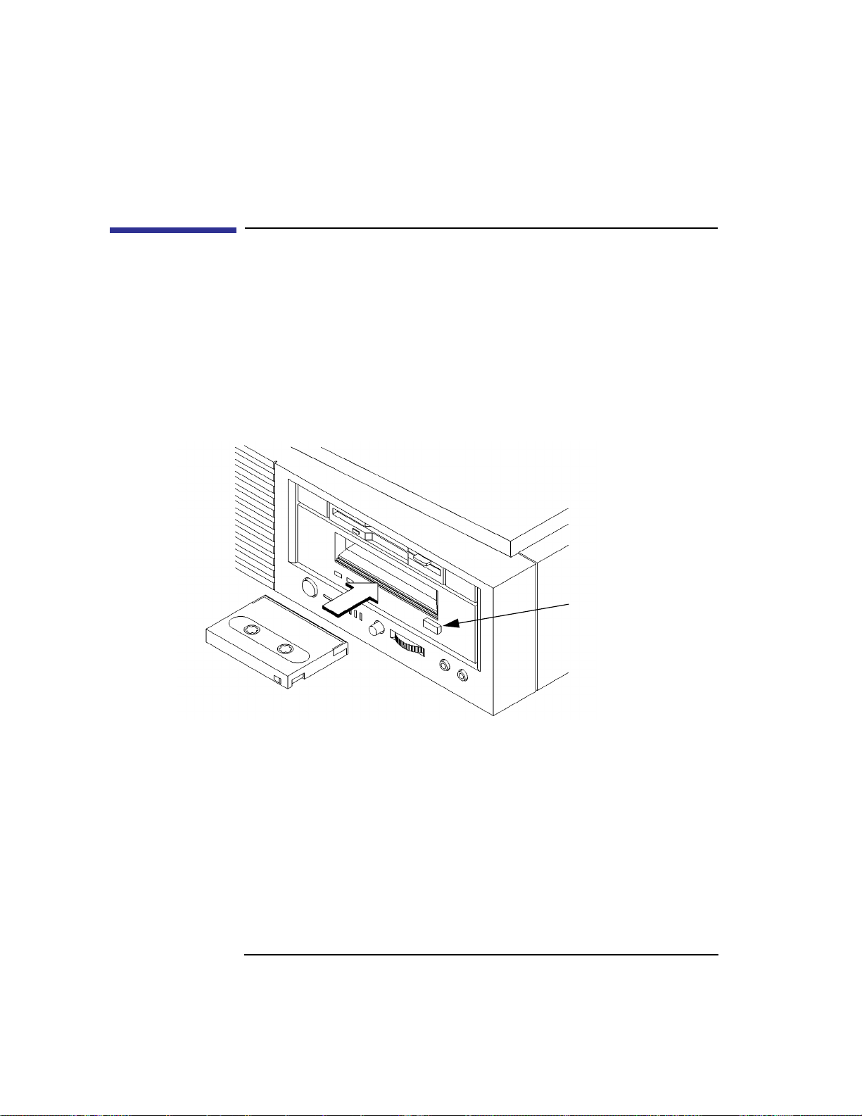
Loading and Unloading a Data Cassette
Follow these steps to load and unload a data cassette from the DDS tape
drive:
1 Insert the data cassette into the drive, as shown in Figure 16.
Figure 16 Loading and Unloading a Data Cassette
2 Push the data cassette about three quarters of the way into the drive. The drive
automatically pulls the data cassette the rest of the way in. When the LEDs on the
front of the drive stop flashing, the drive has loaded the data cassette.
3 T o remove the data cassette, press and release the eject button on the front of the
drive, as shown in Figure 16. The LEDs on the drive flash on and off. T en to twenty seconds later, the data cassette slides partway out of the drive. Remove the cassette from the drive.
56
Eject Button
Page 71

Using Your Digital Data Storage (DDS) Tape Drive
Operating the DDS Tape Drive
Verifying the DDS Tape Drive Operation
T o verify that your workstation can communicate with the DDS-format tape
drive, as root user, enter the following:
/usr/sbin/ioscan -d stape
After a few moments the ioscan utility returns a message similar to the following:
H/W Path Class Description
============================================
bc
8 bc I/O Adapter
8/16 ba Core I/O Adapter
8/16/5 ext_bus Built-in SCSI
8/16/5.3 target
8/16/5.3.0 tape HP HP35480A
If ioscan does not see your tape drive, it will return the following message:
ioscan: No hardware found
If you receive this message, go to Chapter 5, “Solving Problems.”
57
Page 72

Using Your Digital Data Storage (DDS) Tape Drive
Operating the DDS Tape Drive
Using Device Files
Device files are special files that tell your system which system hardware
pathway to use when communicating with a specific device, and what kind
of device it is.
T o determine what device files are available for use with your tape drive, use
the following procedure:
1 In a terminal window, enter the following command:
sam RETURN
2 The System Administration Manager window opens. Double-click on Periph-
eral Devices ->.
3 The Peripheral Devices window opens. Double-click on Tape Drives ->.
4 The Tape Drives window opens.
5 In the list of tape drives, click on the desired tape drive to select it.
6 From the Actions menu, click on Show Device Files.
A window opens with a list of the device files for the selected tape drive with an
explanation of each one.
58
Page 73

Using Your Digital Data Storage (DDS) Tape Drive
Operating the DDS Tape Drive
Archiving Data
This section describes how to transfer data to and from a DDS-format data
cassette (saving and restoring) using the HP-UX tar command and your tape
drive’s device file.
The tar command allows you to save files to a data cassette, restore files
from a data cassette to your system, or list the files on your data cassette.
Writing to a Data Cassette
Use the following instructions to save files to a data cassette:
1 Check that the write-protect tab on the data cassette is in the write position.
2 Load the data cassette into the tape drive.
3 In a terminal window, enter the following command line to write to the tape:
tar -cvf /dev/rmt/devicefile pathname
where devicefile is one of the device files listed from sam and pathname is the
pathname of the file or directory containing files that you want to write to the
tape. To use the data compression mode, use one of the device file names that
sam listed as supporting compression.
59
Page 74

Using Your Digital Data Storage (DDS) Tape Drive
Operating the DDS Tape Drive
Restoring Files from a Data Cassette to Your System
Use the following instructions to restore files from a data cassette to your
system:
1 Load the data cassette into the tape drive.
2 In a terminal window, usecd to change to the directory you want the files to reside
in.
3 Enter the following command line to restore data:
tar -xvf /dev/rmt/devicefile pathname
where devicefile is one of the device files listed from sam and pathname is the
pathname of the file or directory containing files that you want to restore from
the tape. If pathname is not specified, everything on the data cassette is restored.
If the tape was made using data compression, use one of the device file names
that sam listed as supporting compression.
Listing the Files on a Data Cassette
Use the following instructions to list the files on a data cassette:
1 Load the data cassette into the tape drive.
2 In a terminal window, enter the following command line to receive a file listing
of the data cassette:
tar -tvf /dev/rmt/devicefile
where devicefile is one of the device files listed from sam. If the tape was made
with data compression, use one of the device file names that sam listed as sup-
porting compression.
60
Page 75

Using Your Digital Data Storage (DDS) Tape Drive
Operating the DDS Tape Drive
Further Command Information
For additional information on using tar and a complete list of the command
arguments, refer to the tar man page by typing the following:
man tar
The man utility looks up man pages on the system.
You may also communicate with the tape drive with the cpio, ftio, mt, and
fbackup commands. For more information on these commands, enter the
following in a terminal window:
man command
61
Page 76

Using Your Digital Data Storage (DDS) Tape Drive
Troubleshooting
Troubleshooting
If you have trouble with any of these procedures for using your DDS tape
drive, see Chapter 5 of this book, “Solving Problems.”
Ordering Information
To order Hewlett-Packard data cassettes and cleaning cassettes for use in
your DDS tape drive, use the following order numbers:
• HP92283A - Box of five 60-meter DDS data cassettes
• HP92283B - Box of five 90-meter DDS data cassettes
• HP92300A - Box of five 120-meter DDS data cassettes
(not supported on the DDS-DC drives)
• HP92283K - Package of two head-cleaning cassettes
• HP92283L - Lockable storage box for 12 cassettes
CAUTION: Use only data cassettes labeled as DDS (Digital Data Storage) cassettes. Never use
audio cassettes labeled DAT (Digital Audio Tape) in your DDS-format drive.
62
Page 77

4
Using Your 3.5-Inch Floppy Disk Drive
63
Page 78

Using Your 3.5-Inch Floppy Disk Drive
This chapter describes how to perform tasks that allow you to archive to or
transfer data from the optional 3.5-inch floppy disk drive. The information is
organized into the following sections:
• Using the floppy diskette
• Operating the floppy drive
• Troubleshooting
• Ordering information
The instructions in this chapter assume you are using HP-UX version 9.05 or
later operating system with HP VUE version 3.0 or later interface.
NOTICES: When examples of user input are given in this chapter, enter them at the
command-line prompt in an HP VUE terminal window or HP-UX shell.
Some procedures in this chapter require you to log in as root. If you cannot
log in as root, contact your system administrator.
64
Page 79

Using Your 3.5-Inch Floppy Disk Drive
Using the Floppy Diskette
Using the Floppy Diskette
This section describes basic information needed for using your floppy diskettes.
Setting the Write-Protect Tab on a Diskette
You can only store or change information on a diskette when the write-protect tab is in the write position. So, before trying to write to the diskette,
make sure that the write-protect tab is in the write position, as shown in Figure 17.
Push tab up
for write.
Push tab
down for
write-protect
Figure 17 Setting the Write-Protect Tab on a Floppy Diskette
T o protect files on a diskette from being overwritten, set the write-protect tab
to the write-protect position, as shown in Figure 17.
NOTICE: The write-protect tab should always be in the write position for formatting
a new diskette and transferring data to a diskette.
65
Page 80

Using Your 3.5-Inch Floppy Disk Drive
Using the Floppy Diskette
Inserting and Removing a Diskette
Follow these steps to insert and remove a diskette from the floppy disk drive:
1 Insert the diskette into the drive, as shown in Figure 18.
Eject Button
Figure 18 Inserting and Removing a Floppy Diskette
2 Push the diskette into the floppy drive until it clicks into place.
3 To remove the diskette, push the eject button (Figure 18), then take out the dis-
kette.
66
Page 81

Using Your 3.5-Inch Floppy Disk Drive
Operating the Floppy Drive
Operating the Floppy Drive
This section describes how to perform tasks with your 3.5-inch floppy disk
drive.
Verifying the Floppy Drive Configuration
To verify that your workstation can communicate with the floppy drive, use
the ioscan command to see which devices are currently in use on your system.
1 Enter the following at a command prompt:
/sbin/ioscan
After a few moments the ioscan utility lists all of the I/O devices it could find. If
there is a floppy drive in the list, that listing appears similar to the following:
H/W Path Class Description
=========== ============ ===================
8 bc I/O Adapter
8/0 graphics Graphics
8/16/10 pc Built-in Floppy Drive
67
Page 82

Using Your 3.5-Inch Floppy Disk Drive
Operating the Floppy Drive
Using Device Files
Device files are special files that tell your system which system hardware
pathway to use when communicating with a specific device and what kind of
device it is.
To determine what device files are available for use with your floppy drive,
use the following procedure:
1 In a terminal window, enter the following command:
sam RETURN
2 The System Administration Manager window opens. Double-click on
Disks and File Systems->.
3 The Disks and File Systems window opens.
4 In the list of drives, click on the floppy drive listing to select it.
5 From the Actions menu, click on View More Information
A window opens with a list of information for the floppy drive, including the
device files.
68
Page 83

Using Your 3.5-Inch Floppy Disk Drive
Operating the Floppy Drive
Formatting a New Diskette
You must always format a new floppy diskette with the mediainit utility
before using it. To format a new floppy diskette follow these steps:
1 Log in as root.
2 Make sure that the write-protect tab on the floppy diskette is in the write position,
as shown in Figure 17.
3 Insert the diskette into the floppy disk drive.
4 In a terminal window, execute mediainit with an interleave of 2 by entering the
following:
mediainit -i 2 devicefile
where devicefile is the device file as listed by sam.
69
Page 84

Using Your 3.5-Inch Floppy Disk Drive
Operating the Floppy Drive
Transferring Data To and From a Floppy Diskette
This section describes how to transfer data to and from your floppy diskette
(saving and restoring) using the HP-UX tar command with your floppy
drive’s device file.
The tar (tape file archiver) command saves files to a floppy diskette, restores
files from a floppy diskette, or lists files on a floppy diskette.
You need to set the write protect tab to the write position to transfer data to
the diskette. The write-protect tab can be in either position when restoring
data from a diskette or listing the files on a diskette.
Saving Files to a Floppy Diskette
Use the following instructions to save files to a floppy diskette:
1 Check that the write-protect tab on the floppy diskette is in the write position.
2 Load the formatted floppy diskette into the disk drive.
3 In a terminal window, enter the following command line to write to the diskette:
tar -cvf devicefile pathname
where devicefile is the device file as listed by sam and pathname is the pathname
of the file or directory containing files that you want to write to the diskette.
Restoring Files from a Floppy Diskette to Your System
Use the following instructions to restore files from a floppy diskette to your
system:
1 Load the floppy diskette into the disk drive.
2 In a terminal window, use the cd command to change to the directory you want
the files to reside in:
cd directory_path
where directory_path is the pathname of the directory.
70
Page 85

Using Your 3.5-Inch Floppy Disk Drive
Operating the Floppy Drive
3 Enter the following command line:
tar -xvf devicefile pathname
where devicefile is the device file as listed by sam and pathname is the pathname
of the file or directory containing files that you want to restore from the diskette.
If you don’t specify pathname, everything on the floppy diskette is restored.
Listing the Files on a Floppy Diskette
Use the following instructions to list the files on a floppy diskette:
1 Load the floppy diskette into the disk drive.
2 In a terminal window, enter the following command line:
tar -tvf devicefile
where devicefile is the device file as listed by sam.
All files on the floppy diskette are listed.
71
Page 86

Using Your 3.5-Inch Floppy Disk Drive
Operating the Floppy Drive
For More Information
For more information on using tar and a complete list of the command arguments, refer to the tar man page by typing the following in a terminal window:
man tar
The man utility looks up man pages on the system.
You can mount the floppy drive as a file system using the SAM utility. Be
sure to unmount the drive before removing it as a file system. For more
information about how to mount and unmount the floppy drive, see the manual Using HP-UX (B2910-90001).
For more information on copying data to or from your system to other
media, including your floppy diskette, refer to the cpio man page by typing
the following in a terminal window:
man cpio
For more information on copying to or from DOS files, refer to the doscp
man page by typing the following in a terminal window:
man doscp
For more information on listing the contents of DOS directories, refer to the
dosls man page by typing the following in a terminal window:
man dosls
For more information on using your floppy disk drive and floppy diskettes,
refer to the floppy man page by typing the following in a terminal window:
man floppy
For more information on using the mediainit command, refer to the mediainit man page by typing the following in a terminal window:
man mediainit
72
Page 87

Using Your 3.5-Inch Floppy Disk Drive
Operating the Floppy Drive
Configuring the Floppy Driver
If you reload software or rebuild the Instant Ignition system on your workstation, you need to reconfigure the HP-UX Kernel to add the floppy driver.
Use the SAM utility to add the flexible disk driver and build a new HP-UX
kernel.
For more information about how to reconfigure the kernel using SAM, see
the following manuals:
• System Administration Tasks HP 9000 Series 700 Computers (B2355-90040)
• Using HP-UX (B2910-90001)
73
Page 88

Using Your 3.5-Inch Floppy Disk Drive
Troubleshooting
Troubleshooting
If you have trouble with any of these procedures for using your floppy disk
drive, see Chapter 6 of this book, “Solving Problems.”
Ordering Information
To order Hewlett-Packard micro flexible diskettes for use in your 3.5-inch
floppy disk drive, use the following order number:
HP-92192X High-Density Micro Flexible Disks
(1.44MB Formatted Capacity) - box of ten diskettes
74
Page 89

5
Solving Problems
75
Page 90

Solving Problems
This chapter contains information to help you determine what’s wrong with
your system when you have problems. If you have a problem that isn’t listed
in this chapter, or if your problem persists, contact your designated service
representative. When calling for service, always have your system’s model
number and serial number ready.
This chapter is divided into the following sections:
• Common problems and solutions
• Interpreting LED error codes
• Dealing with a boot failure
• Running system verification tests
The instructions in this chapter assume you are using HP-UX version 10.2 or
later operating system with HP VUE version 3.0 or later interface.
76
Page 91

Common Problems and Solutions
The tables in this section list common problems you may encounter with
your workstation. The tables also tell you what to do to help solve the problems.
Problems with Powering Up the System
Table 7 describes possible problems you may encounter when powering up
the system and offers possible solutions.
Table 7 Power Up Problems
Problem Solution
Solving Problems
Common Problems and Solutions
The power LED does not
light.
The power LED lights,
but the screen is blank or
flickers.
If the problem persists, contact your system administrator or call your designated service
representative.
Make sure all AC power cables are connected securely to
the system.
Make sure the power cord is plugged into a working AC
outlet.
Make sure the power switch is set to the ON position.
Press the brightness control on the monitor to adjust it. If
the screen is still blank, turn off the system and monitor
power switches. When the system is completely powered
off, check the video cable connections.
Go to the section “Changing Your Monitor Type” in Appendix B for information about displaying and setting your
workstation’s monitor configuration.
77
Page 92

Solving Problems
Common Problems and Solutions
Problems Loading and Booting the Operating System
Table 8 describes possible problems you may encounter when loading and
booting the operating system and offers solutions.
Table 8 Problems Loading and Booting the Operating System
Problem Solution
The power LED is lit,
and text appears on the
screen, but more than two
minutes have passed with
no sign of system activity.
The system stops or
hangs while booting.
If problem persists, contact your system administrator or call your designated service
representative.
Make sure that all SCSI devices are set to the proper SCSI
ID. (See Appendix C for default SCSI ID settings.)
Check that all SCSI devices are correctly cabled. Check that
the SCSI bus is correctly terminated. (See Appendix C for
information on SCSI cabling and termination).
Follow the instructions in “Dealing With a Boot Failure” in
this chapter.
78
Page 93

Problems with the 802.3 Network
Table 9 describes possible problems you may encounter with the 802.3 network and offers solutions.
Table 9 Problems with the 802.3 Network
Problem Solution
Solving Problems
Common Problems and Solutions
Cannot reach other systems on the network.
Applications that rely on
the network will not run.
Network Auto-Negotiation fails. Systems cannot connect or establish
link.
(Models 132L+/B180)
Check the network connector on the back of the system unit.
Make sure that the network cable or transceiver is fastened
securely to the connector.
The following can cause Auto-Negotiation failure:
• Non-Category 5 cabling. Cabling must be installed by
certified installers.
• Improper cable termination.
• Maximum cable lengths exceeded.
• Incompatibility/Interoperability problems between LAN
devices.
Check the cabling and interfaces for proper installation and
operation. If you know the speed/duplex settings for the
connection device, you can also manually set the workstation LAN interface setting using the Boot Console Iterface,
see “Configure and Display LAN Settings (B132L+/B180L
Only)” on page 222.
When the workstation fails to establish a link using the
LAN-TP(RJ45) connector, the workstation automatically
switches from the LAN-TP(RJ45) connector to the AUI
connector. You can manually set the LAN interface to the
AUI connector using the Boot Console Interface, see “Configure and Display LAN Settings (B132L+/B180L Only)”
on page 222.
If problem persists, contact your system administrator or call your designated service
representative.
79
Page 94

Solving Problems
Common Problems and Solutions
Problems Using a Hard Disk Drive
T able 10 describes possible problems you may encounter using the hard disk
drive and offers solutions.
Table 10 Problems Using a Hard Disk Drive
Problem Solution
The disk drive is not
accessible or does not
respond.
If problems persist, contact your system administrator or call your designated service
representative.
Make sure that all the SCSI devices are set to the proper
SCSI ID. (See Appendix C for default SCSI ID settings.)
Check that all SCSI devices are correctly cabled. Check that
the SCSI bus is correctly terminated. (See Appendix C for
information on SCSI cabling and termination.)
Make sure that the system can communicate with the drive
as described in “Checking the SCSI IDs” in Appendix B.
Follow the instructions in “Dealing With a Boot Failure” in
this chapter.
80
Page 95

Problems Using the CD-ROM Drive
Table 11 describes a possible problem you may encounter when you use the
CD-ROM drive and offers a solution.
Table 11 Problems Using the CD-ROM Drive
Problem Solution
Solving Problems
Common Problems and Solutions
The CD-ROM drive
does not respond to commands.
If problems persist, contact your system administrator or call your designated service
representative
Re-enter the commands and make sure that you have typed
them correctly.
Verify that the CD is mounted.
Make sure that the system can communicate with the drive
as described in “Checking the SCSI IDs” in Appendix B.
Follow the instructions in the section “Running the System
Verification Tests” in this chapter to verify that the CDROM drive is functioning properly.
81
Page 96

Solving Problems
Common Problems and Solutions
Problems Using the DDS Tape Drive
Table 12 describes a possible problem you may encounter using the DDS
tape drive and offers solutions.
Table 12 Problems Using the DDS Tape Drive
Problem Solution
The DDS tape drive does
not respond to commands.
If the problem persists, contact your system administrator or call your designated service
representative.
Re-enter the commands and make sure that you have typed
them correctly.
Make sure that you specified the correct device file name for
commands that require a device file name.
Make sure the write-protect tab is set to write if you are trying to copy data to a data cassette.
Make sure that the system can communicate with the drive
as described in “Checking the SCSI IDs” in Appendix B.
Follow the instructions in the section "Running the System
Verification Tests" in this chapter to verify that the tape
drive is functioning properly.
82
Page 97

Problems Using the Floppy Disk Drive
Table 13 describes a possible problem you may encounter using the floppy
disk drive and offers a solution.
Table 13 Problems Using the Floppy Disk Drive
Problem Solution
Solving Problems
Common Problems and Solutions
The floppy drive does not
respond to commands.
If the problem persists, contact your system administrator or call your designated service
representative.
Re-enter the commands and make sure that you have typed
them correctly.
Make sure that you specified the correct device file for commands that require a device file name.
Make sure that the write-protect tab is set to write if you are
trying to copy data to a floppy diskette.
Use a new floppy diskette.
Follow the instructions in the section "Running the System
Verification Tests" in this chapter to verify that the floppy
drive is functioning properly.
83
Page 98
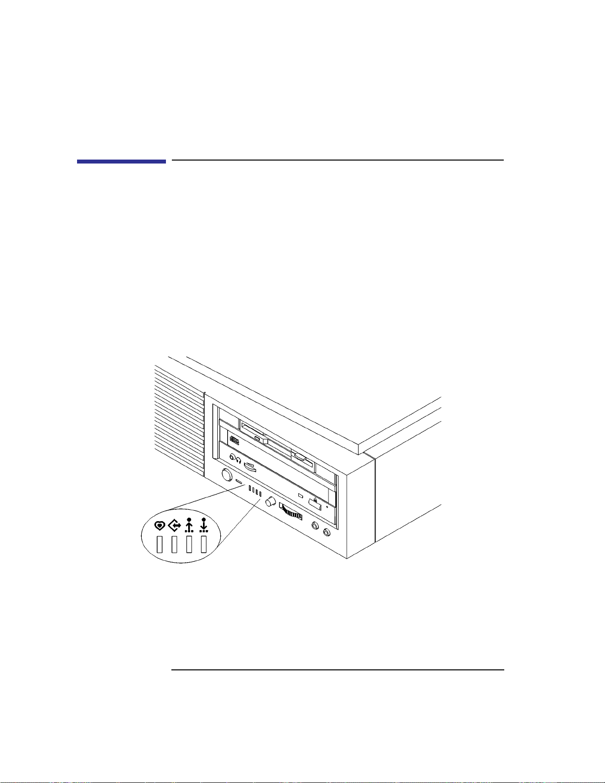
Solving Problems
LED Error Codes
LED Error Codes
This section contains information about the error codes displayed by the
LEDs on the system’s front panel.
If an error occurs during the power-up diagnostics tests, the diagnostics use
the front panel LEDs to display a code for the failing component.
Figure 19 shows the location of the system unit’s front panel LEDs. The four
amber LEDs indicate system status and error codes.
T able 14 shows the LED error codes as they appear on the front panel LEDs.
Use these LED codes to determine the failing component.
Figure 19 System Unit Front Panel LEDs
84
Page 99
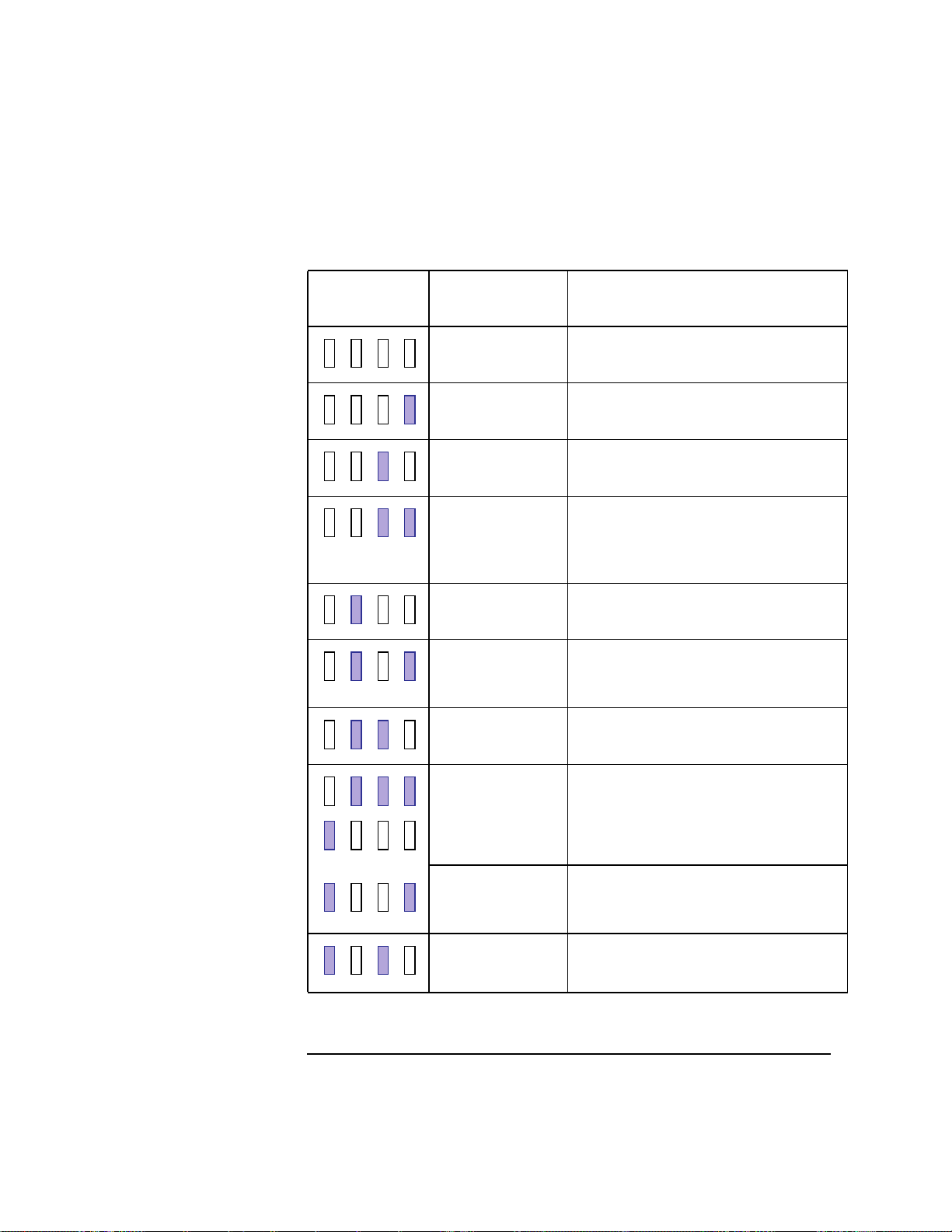
Table 14 LED Error Codes
Solving Problems
LED Error Codes
LED Value
RS-232 Chassis
Code Range
N/A Reserved
7401 No memory found FAULT
Likely cause: SIMMs or processor board
N/A Reserved
FLT 7000-7F00 Memory Error Fault
Likely Cause: Memory SIMMs
System console will indicate which SIMM
fault occurred on
FLT 1030-4099 Processor board FAULT (includes PDH
which could be on I/O board.)
FLT 5000 - 500F
FLT 8000 - 8FFF*
FLT CD00 - CDFF
FLT 8500, 8501
FLT 8C00-8CFF
I/O System FAULT
*Except backplane faults listed below
Backplane FAULT (includes PCI)
Description
Any INIT/TEST
code
Any fault not in
this table including
FLT 1000-101C
FLT CBF0 - CBFF
FLT 1001
INITIALIZATION and TESTING
Note: These two LED codes will alternate
to indicate forward progress: 0111, 1000,
0111,...
Unknown FAULT
HPMC FAULT
85
Page 100

Solving Problems
LED Error Codes
Table 14 LED Error Codes
LED Value
RS-232 Chassis
Code Range
FLT A088 - A0FF No console/IPL error FAULT
N/A Reserved
N/A Reserved
N/A Reserved
N/A Power on value. Indicates processor
board fault when this value remains for
more than a second following power up.
Description
86
 Loading...