

Page 1

HPE Apollo 6500 Gen10 / HPE ProLiant XL270d Gen10 Server User Guide
Abstract
This document is for the person who installs, administers, and troubleshoots servers and storage
systems. Hewlett Packard Enterprise assumes you are qualified in the servicing of computer
equipment and trained in recognizing hazards in products with hazardous energy levels.
Part Number: P05100-002
Published: June 2018
Edition: 2
Page 2

©
Copyright 2018 Hewlett Packard Enterprise Development LP
Notices
The information contained herein is subject to change without notice. The only warranties for Hewlett Packard
Enterprise products and services are set forth in the express warranty statements accompanying such
products and services. Nothing herein should be construed as constituting an additional warranty. Hewlett
Packard Enterprise shall not be liable for technical or editorial errors or omissions contained herein.
Confidential computer software. Valid license from Hewlett Packard Enterprise required for possession, use,
or copying. Consistent with FAR 12.211 and 12.212, Commercial Computer Software, Computer Software
Documentation, and Technical Data for Commercial Items are licensed to the U.S. Government under
vendor's standard commercial license.
Links to third-party websites take you outside the Hewlett Packard Enterprise website. Hewlett Packard
Enterprise has no control over and is not responsible for information outside the Hewlett Packard Enterprise
website.
Acknowledgments
Microsoft® and Windows® are either registered trademarks or trademarks of Microsoft Corporation in the
United States and/or other countries.
Page 3

Contents
Component identification........................................................................... 6
Front panel components......................................................................................................................6
Front panel LEDs and buttons.............................................................................................................6
UID button functionality.............................................................................................................7
Front panel LED power fault codes.......................................................................................... 7
Rear panel components (SXM2 GPU module)....................................................................................8
Rear panel components (PCIe GPU module)..................................................................................... 9
System board components................................................................................................................10
System maintenance switch descriptions............................................................................... 11
NMI functionality..................................................................................................................... 11
DIMM slot locations................................................................................................................ 12
DIMM label identification.........................................................................................................12
SXM2 GPU module components.......................................................................................................14
PCIe GPU module components........................................................................................................ 14
Power distribution board and bus bar components........................................................................... 15
Power supply LED.............................................................................................................................15
Fan module numbering......................................................................................................................16
Supported drives............................................................................................................................... 16
Hot-plug drive LED definitions...........................................................................................................17
NVMe SSD LED definitions...............................................................................................................18
Operations..................................................................................................20
Power up the server.......................................................................................................................... 20
Power down the server......................................................................................................................20
Extending the chassis from the rack..................................................................................................20
Removing the GPU module from the chassis....................................................................................21
Removing the system board module from the chassis......................................................................22
Removing the access panel.............................................................................................................. 23
Removing the fan cage......................................................................................................................23
Removing the riser cage....................................................................................................................24
Setup...........................................................................................................26
Safety and regulatory compliance..................................................................................................... 26
Optional service.................................................................................................................................26
Warnings and cautions......................................................................................................................26
Determining power and cooling configurations..................................................................................28
Power requirements................................................................................................................28
HPE Modular Cooling System 300 and Apollo IT and CDU Rack system..............................28
HPE Apollo System Manager................................................................................................. 28
Hot-plug power supply calculations........................................................................................ 29
Connecting a DC power cable to a DC power source............................................................ 29
Optimum environment....................................................................................................................... 30
Space and airflow requirements............................................................................................. 30
Temperature requirements......................................................................................................31
Electrical grounding requirements.......................................................................................... 31
Identifying the contents of the shipping carton.................................................................................. 31
Installation overview.......................................................................................................................... 32
Installing the chassis into the rack.....................................................................................................32
Contents 3
Page 4

Installing the rails and the cable management arm................................................................ 33
Installing hardware options ...............................................................................................................39
Operating system.............................................................................................................................. 39
Installing the operating system with Intelligent Provisioning...................................................39
Selecting boot options in UEFI Boot Mode........................................................................................39
Selecting boot options....................................................................................................................... 40
Registering the server....................................................................................................................... 40
Hardware options installation.................................................................. 41
Hewlett Packard Enterprise product QuickSpecs..............................................................................41
Introduction........................................................................................................................................41
Installing a power supply................................................................................................................... 41
Installing an 8SFF drive cage............................................................................................................42
Installing a hot-plug SAS or SATA drive............................................................................................ 44
Installing the NVMe enablement kit...................................................................................................45
Installing NVMe drives.......................................................................................................................47
Installing the M.2 SSD enablement option........................................................................................ 48
Installing a DIMM...............................................................................................................................50
Installing a type -a controller..............................................................................................................51
Installing a type -p controller..............................................................................................................52
Installing a full-length PCIe GPU.......................................................................................................53
Configuring PCIe GPU slots................................................................................................... 55
Installing an SXM2 GPU....................................................................................................................56
Installing a PCIe riser board in the SXM2 GPU module.................................................................... 59
Installing a PCIe riser board in the PCIe GPU module......................................................................60
Installing a processor heatsink assembly..........................................................................................61
Installing the HPE Smart Storage Battery......................................................................................... 64
Cabling........................................................................................................66
SAS/SATA cabling............................................................................................................................. 66
NVMe cabling.................................................................................................................................... 67
AC power cabling.............................................................................................................................. 68
Drive power cabling...........................................................................................................................69
Front LED/power/UID cabling............................................................................................................70
GPU module power cabling...............................................................................................................70
HPE Smart Storage Battery cabling.................................................................................................. 70
Software and configuration utilities.........................................................72
Server mode......................................................................................................................................72
Product QuickSpecs..........................................................................................................................72
Active Health System Viewer............................................................................................................ 72
Active Health System..............................................................................................................72
HPE iLO 5..........................................................................................................................................73
iLO Federation........................................................................................................................74
iLO Service Port......................................................................................................................74
iLO RESTful API.....................................................................................................................75
RESTful Interface Tool............................................................................................................75
iLO Amplifier Pack.................................................................................................................. 75
Intelligent Provisioning.......................................................................................................................75
Intelligent Provisioning operation............................................................................................76
Management Security........................................................................................................................76
Scripting Toolkit for Windows and Linux............................................................................................77
UEFI System Utilities.........................................................................................................................77
4 Contents
Page 5

Selecting the boot mode ........................................................................................................77
Secure Boot............................................................................................................................78
Launching the Embedded UEFI Shell ....................................................................................79
HPE Smart Storage Administrator.....................................................................................................79
USB support...................................................................................................................................... 80
External USB functionality...................................................................................................... 80
Redundant ROM support...................................................................................................................80
Safety and security benefits....................................................................................................80
Keeping the system current...............................................................................................................80
Updating firmware or system ROM.........................................................................................80
Drivers.................................................................................................................................... 83
Software and firmware............................................................................................................83
Operating system version support.......................................................................................... 84
HPE Pointnext Portfolio.......................................................................................................... 84
Proactive notifications.............................................................................................................84
Troubleshooting.........................................................................................85
Troubleshooting resources................................................................................................................85
Removing and replacing the system battery.......................................... 86
Specifications............................................................................................ 87
Chassis mechanical specifications....................................................................................................87
Power supply specifications.............................................................................................................. 87
Electrostatic discharge............................................................................. 88
Preventing electrostatic discharge.....................................................................................................88
Grounding methods to prevent electrostatic discharge..................................................................... 88
Websites..................................................................................................... 89
Support and other resources................................................................... 90
Accessing Hewlett Packard Enterprise Support................................................................................ 90
Accessing updates............................................................................................................................ 90
Customer self repair.......................................................................................................................... 91
Remote support.................................................................................................................................91
Warranty information......................................................................................................................... 91
Regulatory information...................................................................................................................... 92
Documentation feedback...................................................................................................................92
Contents 5
Page 6
Component identification
This chapter describes the external and internal server features and components.
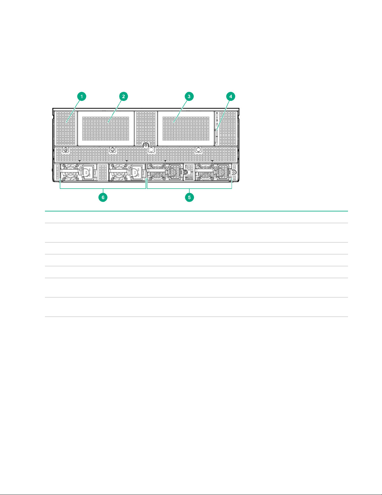
Front panel components
Item Description
1 HPE Smart Storage battery (located behind the
2 Drive bay 1 (for optional 8SFF drive cage)
3 Drive bay 2 (for optional 8SFF drive cage)
4 Serial label pull tab
5 Power supply bays 3 and 4 (for optional HPE 2200 W
6 HPE 2200W Platinum Hot Plug Power Supplies 1
Front panel LEDs and buttons
chassis grill)
Platinum Hot Plug Power Supplies)
and 2 (standard)
6 Component identification
Page 7
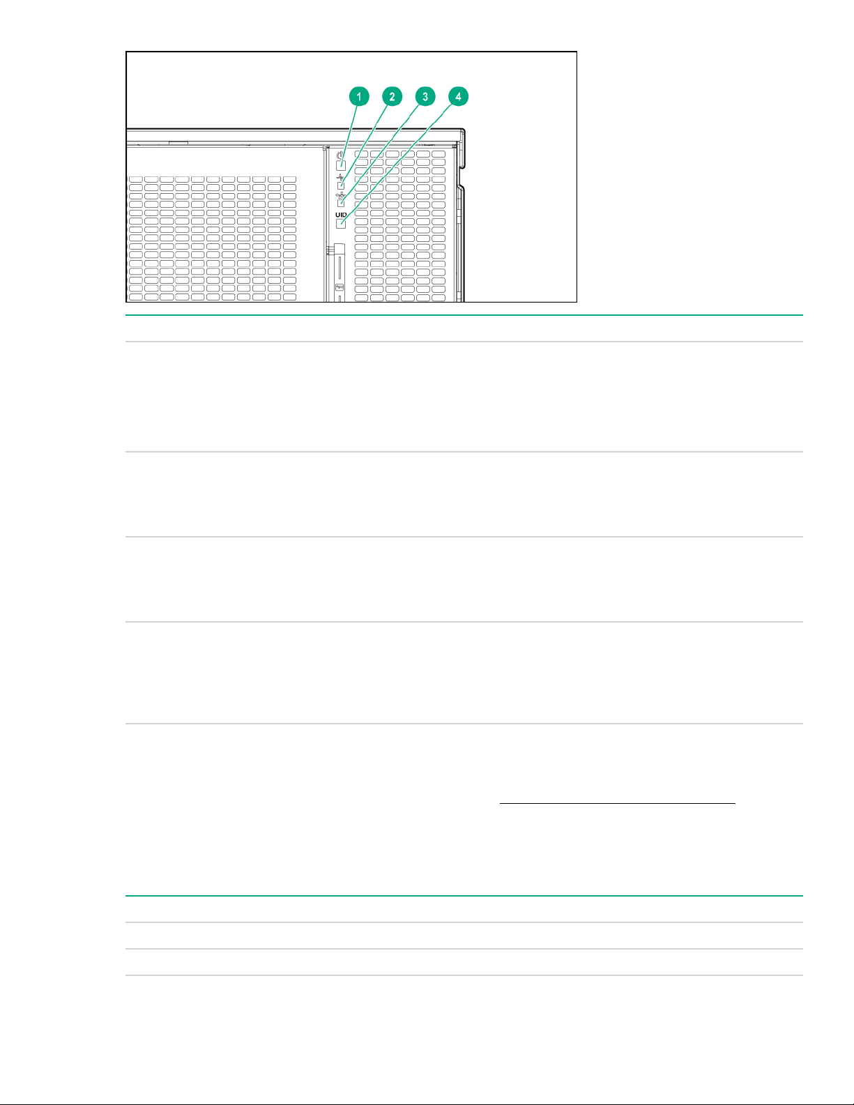
Item Description Status
1 Power on/Standby button and system
power LED
2 Health LED
3 NIC status LED
4 UID button LED
UID button functionality
Solid green = System on
Flashing green = Performing power on sequence
Solid amber = System in standby
Off = No power present
Solid green = Normal
Flashing amber= System degraded
Flashing red = System critical
Solid green = Link to network
Flashing green = Network active
Flashing red = System critical
Solid blue = Activated
Flashing blue = Remote management or firmware
upgrade in progress
Off = Deactivated
The UID button can be used to display the Server Health Summary when the server will not power on. For
more information, see the latest HPE iLO User Guide on the Hewlett Packard Enterprise website.
Front panel LED power fault codes
The following table provides a list of power fault codes, and the subsystems that are affected. Not all power
faults are used by all servers.
Subsystem LED behavior
System board 1 flash
Processor 2 flashes
Table Continued
UID button functionality 7
Page 8
Subsystem LED behavior
Memory 3 flashes
Riser board PCIe slots 4 flashes
FlexibleLOM 5 flashes
Removable HPE Smart Array SR Gen10 controller 6 flashes
System board PCIe slots 7 flashes
Power backplane or storage backplane 8 flashes
Power supply 9 flashes
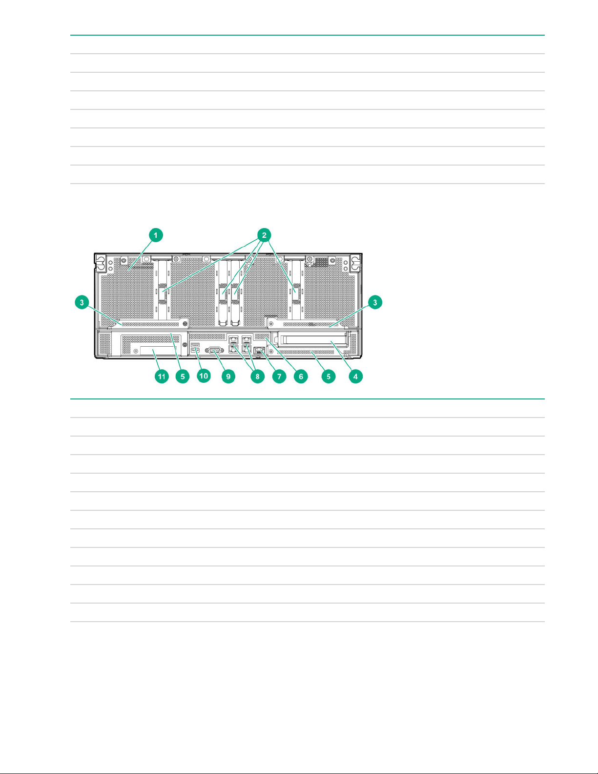
Rear panel components (SXM2 GPU module)
Item Description
1 GPU module
2 PCIe slots 9-12
3 GPU module latches
4 Full Height Half Length PCIe Gen3 slot (system board module)
5 System board module latches
6 System board module
7 Dedicated iLO management port
8 Embedded 4 x 1GbE Network Adapter
9 Video connector
10 USB 3.0 ports
11 FlexibleLOM slot
8 Rear panel components (SXM2 GPU module)
Page 9
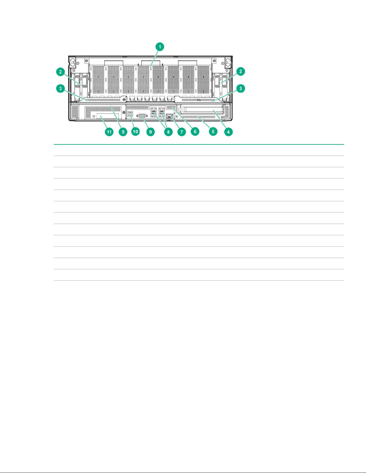
Rear panel components (PCIe GPU module)
Item Description
1 GPU module
2 Low-profile PCIe Gen3 slots 9-12 (GPU module)
3 GPU module latches
4 Full Height Half Length PCIe Gen3 slot (system board module)
5 System board module latches
6 System board module
7 Dedicated iLO management port
8 Embedded 4 x 1GbE Network Adapter
9 Video connector
10 USB 3.0 ports
11 FlexibleLOM slot
Rear panel components (PCIe GPU module) 9
Page 10
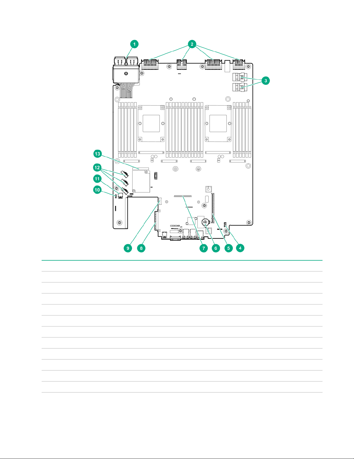
System board components
Item Description
1 Storage connector
2 Midplane connectors
3 NVMe drive ports
4 Internal communication port
5 PCIe riser cage connector
6 System battery
7 Type -a storage controller connector
8 FlexibleLOM connector
9 M.2 riser connector
10 iLO USB connector
11 Internal USB 3.0 connector
Table Continued
10 System board components
Page 11

Item Description
12 X4 embedded SATA ports 1-3
13 System Maintenance Switch
System maintenance switch descriptions
Position Default Function
1
S1
Off
Off = security is enabled.
On = security is disabled.
S2 Off
Off = System configuration can be changed.
On = System configuration is locked.
S3 Off Reserved
S4 Off Reserved
1
S5
Off
Off = Power-on password is enabled.
On = Power-on password is disabled.
S61, 2,
3
Off
Off = No function
On = Restore default manufacturing settings
S7 Off Reserved
S8 — Reserved
S9 — Reserved
S10 — Reserved
S11 — Reserved
S12 — Reserved
1
To access the redundant ROM, set S1, S5, and S6 to On.
2
When the system maintenance switch position 6 is set to the On position, the system is prepared to restore all
configuration settings to their manufacturing defaults.
3
When the system maintenance switch position 6 is set to the On position and Secure Boot is enabled, some
configurations cannot be restored. For more information, see Secure Boot on page 78.
NMI functionality
An NMI crash dump enables administrators to create crash dump files when a system is hung and not
responding to traditional debugging methods.
An analysis of the crash dump log is an essential part of diagnosing reliability problems, such as hanging
operating systems, device drivers, and applications. Many crashes freeze a system, and the only available
action for administrators is to cycle the system power. Resetting the system erases any information that could
support problem analysis, but the NMI feature preserves that information by performing a memory dump
before a hard reset.
To force the OS to invoke the NMI handler and generate a crash dump log, the administrator can use the iLO
Virtual NMI feature.
System maintenance switch descriptions 11
Page 12
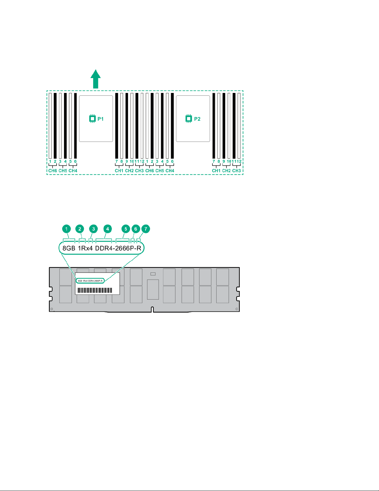
DIMM slot locations
DIMM slots are numbered sequentially (1 through 12) for each processor. The supported AMP modes use the
letter assignments for population guidelines.
The arrow indicates the front of the server.
DIMM label identification
To determine DIMM characteristics, see the label attached to the DIMM. The information in this section helps
you to use the label to locate specific information about the DIMM.
12 DIMM slot locations
Page 13

Item Description Example
1 Capacity
2 Rank
3 Data width on DRAM
4 Memory generation
5 Maximum memory speed
8 GB
16 GB
32 GB
64 GB
128 GB
1R = Single rank
2R = Dual rank
4R = Quad rank
8R = Octal rank
x4 = 4-bit
x8 = 8-bit
x16 = 16-bit
PC4 = DDR4
2133 MT/s
2400 MT/s
2666 MT/s
6 CAS latency
7 DIMM type
For more information about product features, specifications, options, configurations, and compatibility, see the
product QuickSpecs on the Hewlett Packard Enterprise website (http://www.hpe.com/info/qs).
P = CAS 15-15-15
T = CAS 17-17-17
U = CAS 20-18-18
V = CAS 19-19-19 (for RDIMM, LRDIMM)
V = CAS 22-19-19 (for 3DS TSV LRDIMM)
R = RDIMM (registered)
L = LRDIMM (load reduced)
E = Unbuffered ECC (UDIMM)
Component identification 13
Page 14
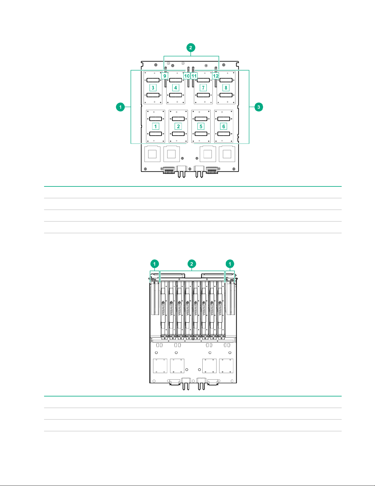
SXM2 GPU module components
Item Description
1 SXM2 GPU slots 1-4
2 PCIe slots 9-12
3 SXM2 GPU slots 5-8
PCIe GPU module components
Item Description
1 Low-profile PCIe Gen3 slots 9-12
2 PCIe GPU slots 1-8
14 SXM2 GPU module components
Page 15
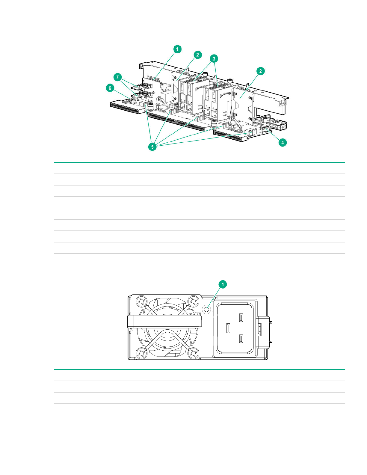
Power distribution board and bus bar components
Item Description
1 NVMe midplane
2 Processor/GPU midplane
3 Power busbars to GPU module
4 Front panel LED connector
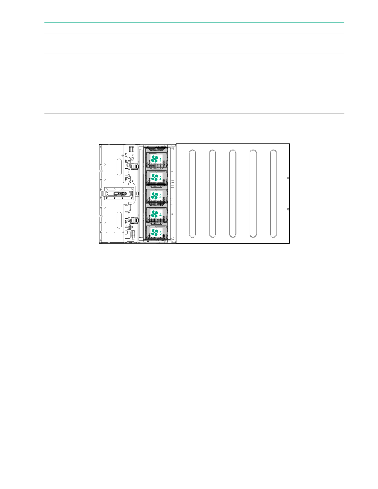
5 Fan connectors 1-5
6 HPE Smart Storage Battery connector
7 NVMe port cable connectors
Power supply LED
Status Description
Solid green Power supply is on and is operating normally.
Flashing green (0.5 Hz) 12 V standby power present (Power supply off)
Table Continued
Power distribution board and bus bar components 15
Page 16
Status Description
Flashing green (2 Hz) Power supply is in Smart redundant state or offline
Solid amber 12 V fault caused a shutdown; power supply failed
Off No power present or standby power failed
Fan module numbering
mode.
(overvoltage/undervoltage, overtemperature,
overcurrent, short-circuit), fan failed, or input
overvoltage protection
(overvoltage/undervoltage, overtemperature,
overcurrent, short-circuit, fan lock)
Supported drives
When one drive cage is installed, the following drive configurations are supported:
• 2 NVMe + 6 SATA
• 2 NVMe + 6 SAS
• 8 SAS/SATA when one of the following controllers is installed
◦ P408i-p
◦ P408i-a
◦ P816i-a
• Embedded SATA: 6 SATA drives
When two drive cages are installed, the following drive configurations are supported:
• 4 NVMe (2/2) + 12 SATA (6/4)
• 4 NVMe (2/2) + 12 SAS (6/6)
• 16 SATA (p816i-a)
16 Fan module numbering
Page 17
• 16 SAS/SATA (p408i-a + p408i-p)
• Embedded SATA: 12 SATA (6/6)
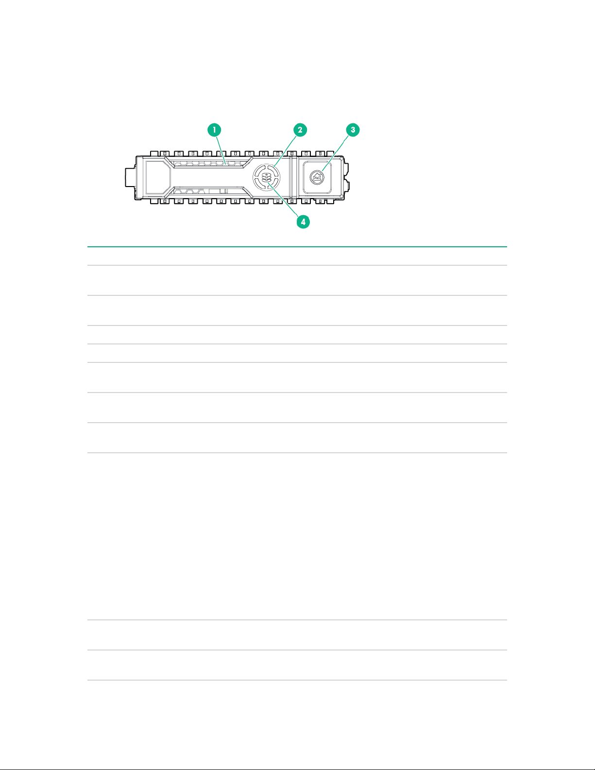
Hot-plug drive LED definitions
Item LED Status Definition
1 Locate Solid blue The drive is being identified by a host
Flashing blue The drive carrier firmware is being updated or
application.
requires an update.
2 Activity ring Rotating green Drive activity.
Off No drive activity.
3 Do not remove Solid white Do not remove the drive. Removing the drive
causes one or more of the logical drives to fail.
Off Removing the drive does not cause a logical
drive to fail.
4 Drive status Solid green The drive is a member of one or more logical
drives.
Flashing green The drive is doing one of the following:
• Rebuilding
• Performing a RAID migration
• Performing a strip size migration
• Performing a capacity expansion
• Performing a logical drive extension
• Erasing
• Spare part activation
Flashing amber/
green
Flashing amber The drive is not configured and predicts the
The drive is a member of one or more logical
drives and predicts the drive will fail.
drive will fail.
Table Continued
Hot-plug drive LED definitions 17
Page 18
Item LED Status Definition
Solid amber The drive has failed.
Off The drive is not configured by a RAID
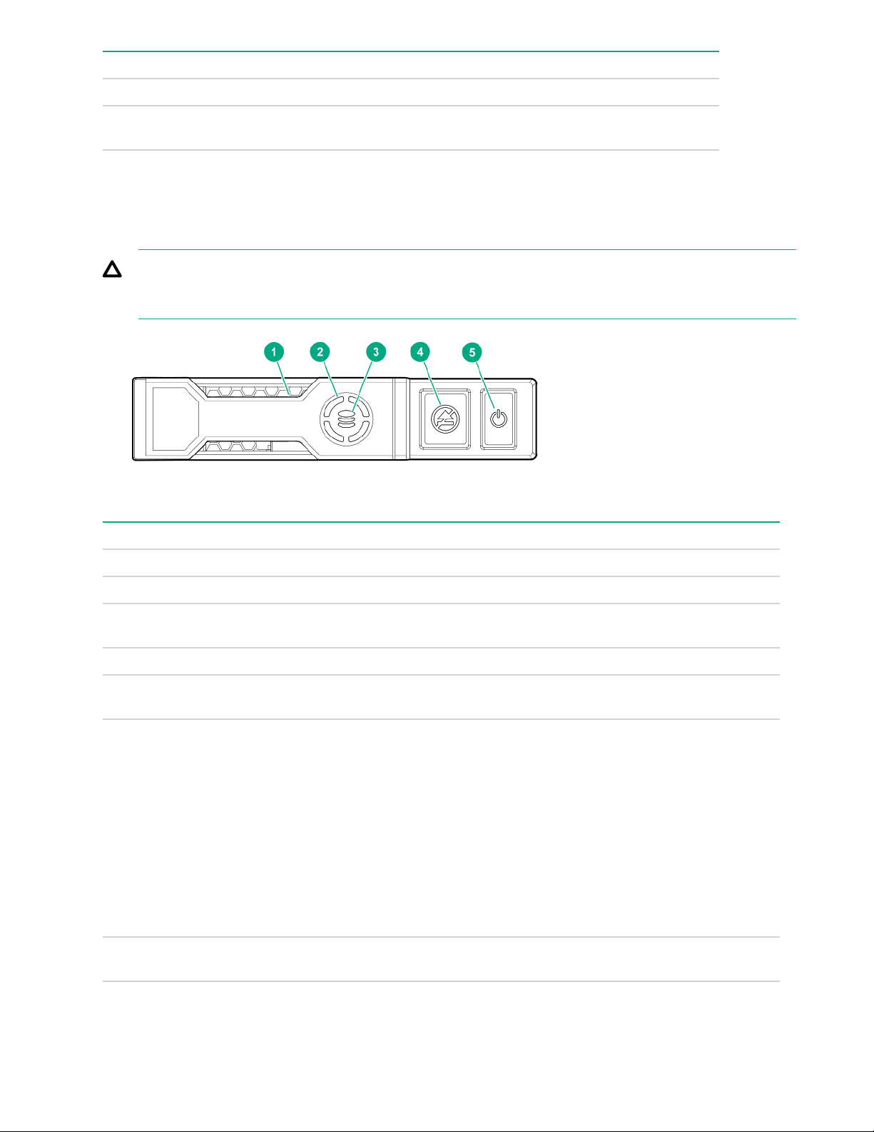
NVMe SSD LED definitions
The NVMe SSD is a PCIe bus device. A device attached to a PCIe bus cannot be removed without allowing
the device and bus to complete and cease the signal/traffic flow.
CAUTION: Do not remove an NVMe SSD from the drive bay while the Do not remove LED is flashing.
The Do not remove LED flashes to indicate that the device is still in use. Removing the NVMe SSD
before the device has completed and ceased signal/traffic flow can cause loss of data.
controller or a spare drive.
Item LED Status Definition
1 Locate Solid blue The drive is being identified by a host application.
Flashing blue The drive carrier firmware is being updated or requires an update.
2 Activity
ring
Off No drive activity
3 Drive
status
Flashing green The drive is doing one of the following:
Rotating green Drive activity
Solid green The drive is a member of one or more logical drives.
• Rebuilding
• Performing a RAID migration
• Performing a stripe size migration
• Performing a capacity expansion
• Performing a logical drive extension
• Erasing
Flashing amber/
green
18 NVMe SSD LED definitions
The drive is a member of one or more logical drives and predicts the
drive will fail.
Table Continued
Page 19

Item LED Status Definition
Flashing amber The drive is not configured and predicts the drive will fail.
Solid amber The drive has failed.
Off The drive is not configured by a RAID controller.
4 Do not
remove
Flashing white The drive ejection request is pending.
5 Power Solid green Do not remove the drive. The drive must be ejected from the PCIe bus
Solid white Do not remove the drive. The drive must be ejected from the PCIe bus
prior to removal.
Off The drive has been ejected.
prior to removal.
Flashing green The drive ejection request is pending.
Off The drive has been ejected.
Component identification 19
Page 20

Operations
Power up the server
To power up the server, use one of the following methods:
• Press the Power On/Standby button.
• Use the virtual power button through iLO.
Power down the server
Before powering down the server for any upgrade or maintenance procedures, perform a backup of critical
server data and programs.
IMPORTANT: When the server is in standby mode, auxiliary power is still being provided to the system.
To power down the server, use one of the following methods:
• Press and release the Power On/Standby button.
This method initiates a controlled shutdown of applications and the OS before the server enters standby
mode.
• Press and hold the Power On/Standby button for more than 4 seconds to force the server to enter standby
mode.
This method forces the server to enter standby mode without properly exiting applications and the OS. If
an application stops responding, you can use this method to force a shutdown.
• Use a virtual power button selection through .
This method initiates a controlled remote shutdown of applications and the OS before the server enters
standby mode.
Before proceeding, verify that the server is in standby mode by observing that the system power LED is
amber.
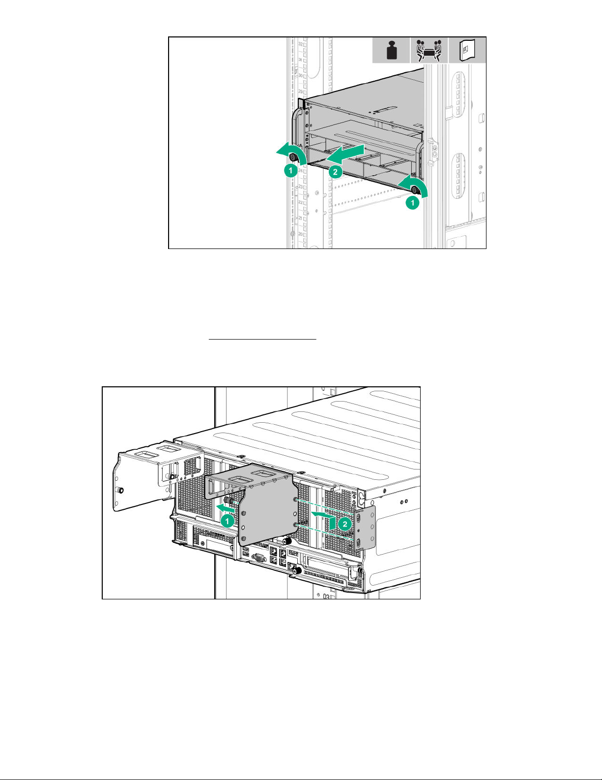
Extending the chassis from the rack
Procedure
Loosen the thumbscrews on either side of the chassis, and then extend the chassis from the rack.
20 Operations
Page 21
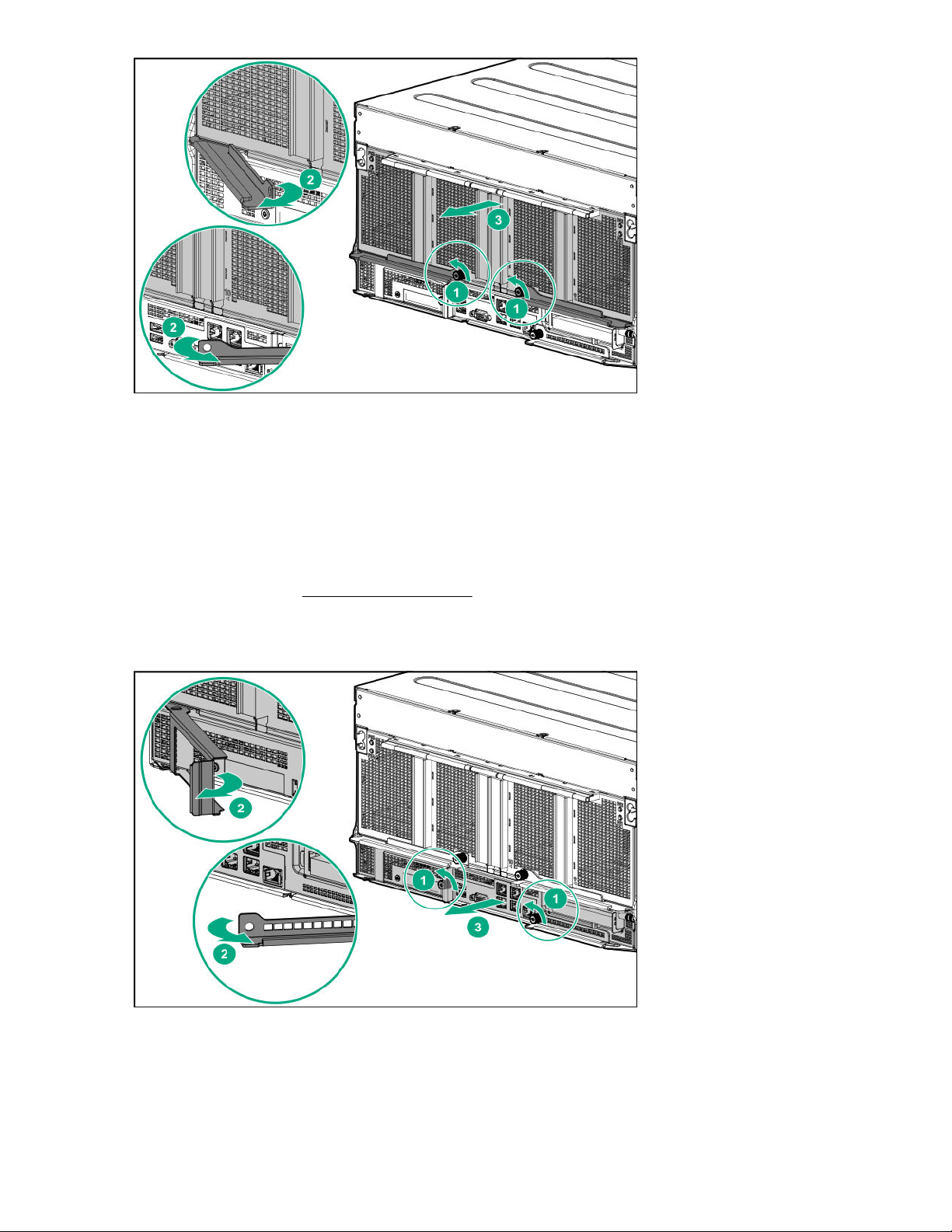
Removing the GPU module from the chassis
Procedure
1. Power down the server (Power down the server on page 20).
2. Disconnect all peripheral cables from the GPU module.
3. If installed, remove the power cord guides.
4. Remove the GPU module from the chassis.
Depending on the chassis configuration, your GPU module might look different.
Removing the GPU module from the chassis 21
Page 22
5. Place the module on a flat, level work surface.
Removing the system board module from the chassis
Procedure
1. Back up all server data.
2. Power down the server (Power down the server on page 20).
3. Disconnect all peripheral cables from the server.
4. Remove the server from the chassis.
5. Place the module on a flat, level work surface.
22 Removing the system board module from the chassis
Page 23
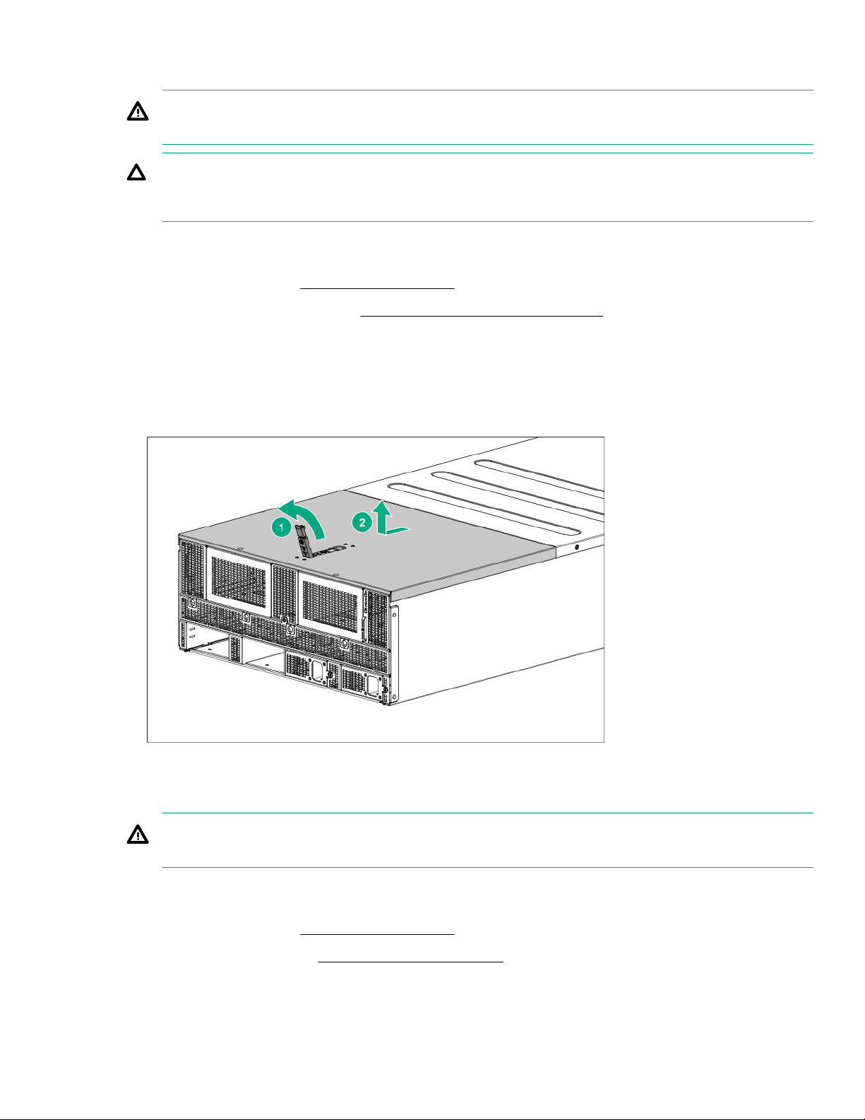
Removing the access panel
WARNING: To reduce the risk of personal injury from hot surfaces, allow the drives and the internal
system components to cool before touching them.
CAUTION: Do not operate the chassis for long periods with the access panel open or removed.
Operating the chassis in this manner results in improper airflow and improper cooling that can lead to
thermal damage.
Procedure
1. Power down the server (Power down the server on page 20).
2. Extend the chassis from the rack (Extending the chassis from the rack on page 20).
3. If the locking latch is locked, use a T-15 Torx screwdriver to unlock the latch.
4. Open the locking latch.
The access panel slides back, releasing it from the chassis.
5. Lift and remove the access panel.
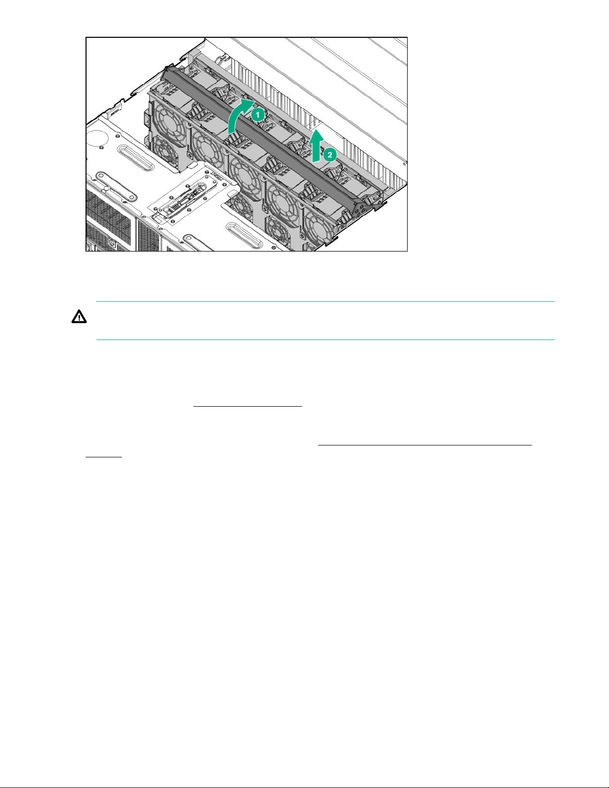
Removing the fan cage
WARNING: To reduce the risk of personal injury from hot surfaces, allow the drives and the internal
system components to cool before touching them.
Procedure
1. Power down the server (Power down the server on page 20).
2. Remove the access panel (Removing the access panel on page 23).
3. Remove the fan cage.
Removing the access panel 23
Page 24
Removing the riser cage
WARNING: To reduce the risk of personal injury from hot surfaces, allow the drives and the internal
system components to cool before touching them.
Procedure
1. Back up all server data.
2. Power down the server (Power down the server on page 20).
3. Disconnect all peripheral cables from the server.
4. Remove the system board module from the chassis (Removing the system board module from the
chassis on page 22).
5. Place the module on a flat, level work surface.
6. Remove the riser cage.
24 Removing the riser cage
Page 25
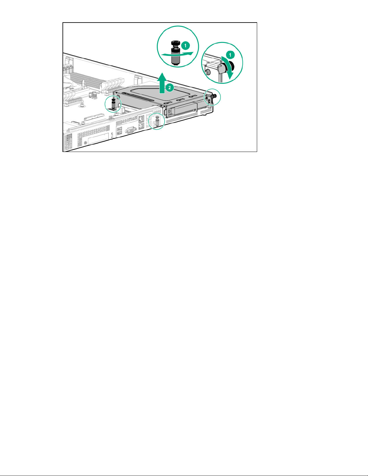
To replace the component, reverse the removal procedure.
Operations 25
Page 26

Setup
Safety and regulatory compliance
For important safety, environmental, and regulatory information, see Safety and Compliance Information for
Server, Storage, Power, Networking, and Rack Products, available at the Hewlett Packard Enterprise website
http://www.hpe.com/support/Safety-Compliance-EnterpriseProducts).
(
Optional service
Delivered by experienced, certified engineers, Hewlett Packard Enterprise support services help you keep
your servers up and running with support packages tailored specifically for HPE ProLiant systems. Hewlett
Packard Enterprise support services let you integrate both hardware and software support into a single
package. A number of service level options are available to meet your business and IT needs.
Hewlett Packard Enterprise support services offer upgraded service levels to expand the standard product
warranty with easy-to-buy, easy-to-use support packages that will help you make the most of your server
investments. Some of the Hewlett Packard Enterprise support services for hardware, software or both are:
• Foundation Care – Keep systems running.
◦ 6-Hour Call-to-Repair
◦ 4-Hour 24x7
◦ Next Business Day
• Proactive Care – Help prevent service incidents and get you to technical experts when there is one.
◦ 6-Hour Call-to-Repair
◦ 4-Hour 24x7
◦ Next Business Day
• Deployment service for both hardware and software
• Hewlett Packard Enterprise Education Services – Help train your IT staff.
1
The time commitment for this repair service might vary depending on the site's geographical region. For
more service information available in your site, contact your local Hewlett Packard Enterprise support
center.
For more information on Hewlett Packard Enterprise support services, see the Hewlett Packard Enterprise
website.
1
1
Warnings and cautions
WARNING: To reduce the risk of personal injury or damage to equipment, heed all warnings and
cautions throughout the installation instructions.
26 Setup
Page 27
WARNING: To reduce the risk of personal injury or damage to the equipment, be sure that:
• The rack is bolted to the floor using the concrete anchor kit.
• The leveling feet extend to the floor.
• The full weight of the rack rests on the leveling feet.
• The racks are coupled together in multiple rack installations.
• Only one component is extended at a time. If more than one component is extended, a rack might
become unstable.
WARNING: The chassis is very heavy. To reduce the risk of personal injury or damage to the
equipment:
• Observe local occupational health and safety requirements and guidelines for manual material
handling.
• Remove all servers from the chassis before installing or moving the chassis.
• Use caution and get help to lift and stabilize the chassis during installation or removal, especially
when the chassis is not fastened to the rack.
WARNING: To reduce the risk of personal injury or damage to the equipment, you must adequately
support the chassis during installation and removal.
WARNING: Install the chassis starting from the bottom of the rack and work your way up the rack.
WARNING: To reduce the risk of personal injury from hot surfaces, allow the drives and the internal
system components to cool before touching them.
WARNING: To reduce the risk of electric shock or damage to the equipment:
• Never reach inside the chassis while the system is powered up.
• Perform service on system components only as instructed in the user documentation.
CAUTION: Always be sure that equipment is properly grounded and that you follow proper grounding
procedures before beginning any installation procedure. Improper grounding can result in ESD damage
to electronic components. For more information, refer to "Electrostatic discharge on page 88."
CAUTION: When performing non-hot-plug operations, you must power down the server and/or the
system. However, it may be necessary to leave the server powered up when performing other
operations, such as hot-plug installations or troubleshooting.
CAUTION: Do not operate the server for long periods with the access panel open or removed.
Operating the server in this manner results in improper airflow and improper cooling that can lead to
thermal damage.
Setup 27
Page 28

Determining power and cooling configurations
Validate power and cooling requirements based on location and installed components.
Power requirements
Installation of this equipment must comply with local and regional electrical regulations governing the
installation of IT equipment by licensed electricians. This equipment is designed to operate in installations
covered by NFPA 70, 1999 Edition (National Electric Code) and NFPA-75, 1992 (code for Protection of
Electronic Computer/Data Processing Equipment). For electrical power ratings on options, refer to the product
rating label or the user documentation supplied with that option.
WARNING: To reduce the risk of personal injury, fire, or damage to the equipment, do not overload the
AC supply branch circuit that provides power to the rack. Consult the electrical authority having
jurisdiction over wiring and installation requirements of your facility.
CAUTION: Protect the server from power fluctuations and temporary interruptions with a regulating
UPS. This device protects the hardware from damage caused by power surges and voltage spikes and
keeps the server in operation during a power failure.
HPE Modular Cooling System 300 and Apollo IT and CDU Rack system
The HPE Modular Cooling System 300 and Apollo IT and CDU Rack system is a high-density, energyefficient, sustainable high-performance computing solution that uses an innovative warm-liquid cooling
technology to fuel the future of supercomputing. It offers a modular, rack-based system that is easy to install,
maintain, and monitor. The hot water "waste heat" can be recycled to heat the data center efficiently.
For more information, see the HPE Modular Cooling System 300 and Apollo IT and CDU Rack User Guide on
the Hewlett Packard Enterprise website (http://www.hpe.com/info/XL270dGen10-docs).
HPE Apollo Environmental Module
The HPE Apollo Environmental Module is installed in the rack and connects to the rack leak detectors and
sensors to monitor environmental variables, such as temperature and humidity. This information is accessible
using the HPE Apollo Platform Manager.
For more information, see the following documentation on the Hewlett Packard Enterprise website (http://
www.hpe.com/info/XL270dGen10-docs):
• HPE Apollo Platform Manager User Guide
• HPE Modular Cooling System 300 and Apollo IT and CDU Rack User Guide
HPE Apollo System Manager
Apollo System Manager provides a comprehensive, central pane of glass to view the state of the Apollo
warm-water-cooling and power infrastructure. It also provides email alerts when preconfigured events occur.
All sensor data is gathered and archived for plotting, analysis, and to assist with any support issues.
For more information, see the HPE Apollo System Manager User Guide on the Hewlett Packard Enterprise
website (http://www.hpe.com/info/XL270dGen10-docs).
28 Determining power and cooling configurations
Page 29

Hot-plug power supply calculations
For more information on the hot-plug power supply and calculators to determine server power consumption in
various system configurations, see the Hewlett Packard Enterprise Power Advisor website (http://
www.hpe.com/info/poweradvisor/online).
Connecting a DC power cable to a DC power source
WARNING: To reduce the risk of electric shock or energy hazards:
• This equipment must be installed by trained service personnel, as defined by the NEC and IEC
60950-1, Second Edition, the standard for Safety of Information Technology Equipment.
• Connect the equipment to a reliably grounded Secondary circuit source. A Secondary circuit has no
direct connection to a Primary circuit and derives its power from a transformer, converter, or
equivalent isolation device.
• The branch circuit overcurrent protection must be rated 27 A.
WARNING: When installing a DC power supply, the ground wire must be connected before the positive
or negative leads.
WARNING: Remove power from the power supply before performing any installation steps or
maintenance on the power supply.
CAUTION: The server equipment connects the earthed conductor of the DC supply circuit to the
earthing conductor at the equipment. For more information, see the documentation that ships with the
power supply.
CAUTION: If the DC connection exists between the earthed conductor of the DC supply circuit and the
earthing conductor at the server equipment, the following conditions must be met:
• This equipment must be connected directly to the DC supply system earthing electrode conductor or
to a bonding jumper from an earthing terminal bar or bus to which the DC supply system earthing
electrode conductor is connected.
• This equipment should be located in the same immediate area (such as adjacent cabinets) as any
other equipment that has a connection between the earthed conductor of the same DC supply circuit
and the earthing conductor, and also the point of earthing of the DC system. The DC system should
be earthed elsewhere.
• The DC supply source is to be located within the same premises as the equipment.
• Switching or disconnecting devices should not be in the earthed circuit conductor between the DC
source and the point of connection of the earthing electrode conductor.
To connect a DC power cable to a DC power source:
1. Cut the DC power cord ends no shorter than 150 cm (59.06 in).
2. If the power source requires ring tongues, use a crimping tool to install the ring tongues on the power cord
wires.
Hot-plug power supply calculations 29
Page 30

IMPORTANT: The ring terminals must be UL approved and accommodate 12 gauge wires.
IMPORTANT: The minimum nominal thread diameter of a pillar or stud type terminal must be 3.5
mm (0.138 in); the diameter of a screw type terminal must be 4.0 mm (0.157 in).
3. Stack each same-colored pair of wires and then attach them to the same power source. The power cord
consists of three wires (black, red, and green).
For more information, see the documentation that ships with the power supply.
Optimum environment
When installing the server in a rack, select a location that meets the environmental standards described in
this section.
Space and airflow requirements
To allow for servicing and adequate airflow, observe the following space and airflow requirements when
deciding where to install a rack:
• Leave a minimum clearance of 63.5 cm (25 in) in front of the rack.
• Leave a minimum clearance of 76.2 cm (30 in) behind the rack.
• Leave a minimum clearance of 121.9 cm (48 in) from the back of the rack to the back of another rack or
row of racks.
Hewlett Packard Enterprise servers draw in cool air through the front door and expel warm air through the
rear door. Therefore, the front and rear rack doors must be adequately ventilated to allow ambient room air to
enter the cabinet, and the rear door must be adequately ventilated to allow the warm air to escape from the
cabinet.
CAUTION: To prevent improper cooling and damage to the equipment, do not block the ventilation
openings.
When vertical space in the rack is not filled by a server or rack component, the gaps between the components
cause changes in airflow through the rack and across the servers. Cover all gaps with blanking panels to
maintain proper airflow.
CAUTION: Always use blanking panels to fill empty vertical spaces in the rack. This arrangement
ensures proper airflow. Using a rack without blanking panels results in improper cooling that can lead to
thermal damage.
The 9000 and 10000 Series Racks provide proper server cooling from flow-through perforations in the front
and rear doors that provide 64 percent open area for ventilation.
CAUTION: When using a Compaq branded 7000 series rack, install the high airflow rack door insert
(PN 327281-B21 for 42U rack, PN 157847-B21 for 22U rack) to provide proper front-to-back airflow and
cooling.
30 Optimum environment
Page 31

CAUTION: If a third-party rack is used, observe the following additional requirements to ensure
adequate airflow and to prevent damage to the equipment:
• Front and rear doors—If the 42U rack includes closing front and rear doors, you must allow 5,350 sq
cm (830 sq in) of holes evenly distributed from top to bottom to permit adequate airflow (equivalent to
the required 64 percent open area for ventilation).
• Side—The clearance between the installed rack component and the side panels of the rack must be
a minimum of 7 cm (2.75 in).
Temperature requirements
To ensure continued safe and reliable equipment operation, install or position the system in a well-ventilated,
climate-controlled environment.
The maximum recommended ambient operating temperature (TMRA) for most server products is 35°C
(95°F). The temperature in the room where the rack is located must not exceed 35°C (95°F).
CAUTION: To reduce the risk of damage to the equipment when installing third-party options:
• Do not permit optional equipment to impede airflow around the server or to increase the internal rack
temperature beyond the maximum allowable limits.
• Do not exceed the manufacturer’s TMRA.
Electrical grounding requirements
The server must be grounded properly for proper operation and safety. In the United States, you must install
the equipment in accordance with NFPA 70, 1999 Edition (National Electric Code), Article 250, as well as any
local and regional building codes. In Canada, you must install the equipment in accordance with Canadian
Standards Association, CSA C22.1, Canadian Electrical Code. In all other countries, you must install the
equipment in accordance with any regional or national electrical wiring codes, such as the International
Electrotechnical Commission (IEC) Code 364, parts 1 through 7. Furthermore, you must be sure that all
power distribution devices used in the installation, such as branch wiring and receptacles, are listed or
certified grounding-type devices.
Because of the high ground-leakage currents associated with multiple servers connected to the same power
source, Hewlett Packard Enterprise recommends the use of a PDU that is either permanently wired to the
building’s branch circuit or includes a nondetachable cord that is wired to an industrial-style plug. NEMA
locking-style plugs or those complying with IEC 60309 are considered suitable for this purpose. Using
common power outlet strips for the server is not recommended.
Identifying the contents of the shipping carton
Unpack the shipping carton and locate the materials and documentation necessary for installing the chassis .
All the rack mounting hardware necessary for installing the chassis into the rack is included with the rack or
the chassis.
The contents of the shipping carton include:
• Chassis
• Power cord
Temperature requirements 31
Page 32

• Hardware documentation and software products
• Rack-mounting hardware and documentation
You might also need the following items:
• Operating system or application software
• Hardware options
• Screwdrivers
◦ T-10 Torx
◦ T-15 Torx
◦ T-30 Torx
Installation overview
Installation of a server requires the following steps:
Procedure
1. Install the chassis into the rack (Installing the chassis into the rack on page 32).
2. Install any server options. (Installing hardware options on page 39).
3. Install the operating system (Operating system on page 39).
4. Install system software.
5. Register the server (Registering the server on page 40).
Installing the chassis into the rack
CAUTION: Always plan the rack installation so that the heaviest item is on the bottom of the rack. Install
the heaviest item first, and continue to populate the rack from the bottom to the top.
Prerequisites
Before installing the chassis, observe all necessary warnings and cautions.
Procedure
1. Unpack the system and remove all components from the chassis.
2. Install the chassis and cable management arm into the rack. For more information, see the installation
instructions that ship with the selected rail system.
3. Install options in the chassis.
4. Install all components in their original locations in the chassis.
5. Connect the power cords to the rear of the chassis.
6. Connect the system to the power source.
32 Installation overview
Page 33

WARNING: To reduce the risk of electric shock or damage to the equipment:
• Do not disable the power cord grounding plug. The grounding plug is an important safety feature.
• Plug the power cord into a grounded (earthed) electrical outlet that is easily accessible at all
times.
• Unplug the power cord from the power supply to disconnect power to the equipment.
• Do not route the power cord where it can be walked on or pinched by items placed against it. Pay
particular attention to the plug, electrical outlet, and the point where the cord extends from the
server.
Installing the rails and the cable management arm
Installation hardware
In kits supporting 1075 mm racks, the cable management arm and the power cord management brackets are
not included.
Item Hardware (Scale 1:1) Quantity/Tool
A 4 10-32 panhead shoulder screw
T-25 Torx
B 2 10-32 slotted screws T-25 Torx
C 1 square-hole cage nut
Prerequisites for installation
Procedure
1. Observe the following:
CAUTION: Always plan the rack installation so that the heaviest item is on the bottom of the rack.
Install the heaviest item first, and continue to populate the rack from the bottom to the top.
Only 2 are used when the cable
management arm is installed.
For cable management arm only
For cable management arm only
Installing the rails and the cable management arm 33
Page 34

CAUTION: If installing the chassis in a 1075 mm rack, observe the following:
• To enable the chassis to fit in the 1075 mm rack, do not install the cable management arm or the
power cord management brackets.
• When the cable management arm is not installed, hot-plug fan functionality is not supported. The
cable management arm is required to remove the fans without removing power or connectivity.
• High-density PDUs are not supported when the chassis is installed in a 1075 mm rack.
2. Ensure the distance between the front and rear RETMA rails is between 73.66 cm (29 inches) and 78.74
cm (31 inches). If needed, adjust the rear RETMA rail.
3. If installing more than one chassis in a standard rack, plan the rail installation so that the cable
management arms can be installed in alternating positions for each chassis.
Installing the rails
Procedure
•
•
NOTE:
◦ If installing the cable management arm on the right, perform the following action on the other rail.
◦ In a 1075 mm rack, perform the following action on both rails (4 screws total).
34 Installing the rails
Page 35

•
NOTE:
◦ If installing the chassis in a 1075 mm rack, skip the following step and go to "Installing the product in
the rack."
◦ If installing the cable management arm on the right, perform the following action on the other rail.
Setup 35
Page 36

Installing the cable management arm
Procedure
•
NOTE:
◦ If installing the cable management arm on the left, it can be installed as is from the kit. Go to the next
step.
◦ If installing the cable management arm on the right, perform the following step to prepare the cable
management arm.
•
NOTE: For the following step, the orientation and installation of the bracket and screws on the cable
management arm is the same for both sides.
36 Installing the cable management arm
Page 37

•
Installing the product in the rack
WARNING: To reduce the risk of personal injury or equipment damage, be sure that the rack is
adequately stabilized before installing the chassis.
WARNING: To reduce the risk of personal injury or equipment damage, do one the following:
• If the chassis is empty, use at least 2 people to lift and stabilize the product pieces during assembly.
• If the chassis is fully loaded, use at least 4 people to lift and stabilize the product pieces during
assembly.
• Use a lift that can handle the load of the product.
Installing the product in the rack 37
Page 38

CAUTION: Be sure to keep the product parallel to the floor when installing the chassis. Tilting the
product up or down could result in damage to the slides.
Procedure
WARNING: On both sides, align the three alignment pins on the chassis with the channel in the rails.
Otherwise, the chassiscan fall if the rack is moved or shipped.
Multiple chassis installed in a rack
When installing multiple chassis in a standard rack, be sure that the cable management arms are installed in
alternating positions.
38 Multiple chassis installed in a rack
Page 39

Installing hardware options
Install any hardware options before initializing the server. For options installation information, refer to the
option documentation. For server-specific information, refer to "Hardware options installation."
Operating system
This ProLiant server does not ship with provisioning media. Everything required to manage and install the
system software and firmware is preloaded on the server.
To operate properly, the server must have a supported operating system. Attempting to run an unsupported
operating system can cause serious and unpredictable results. For the latest information on operating system
support, see the
Failure to observe UEFI requirements for ProLiant Gen10 servers can result in errors installing the operating
system, failure to recognize boot media, and other boot failures. For more information on these requirements,
see the HPE UEFI Requirements on the Hewlett Packard Enterprise website.
To install an operating system on the server, use one of the following methods:
• Intelligent Provisioning—For single-server deployment, updating, and provisioning capabilities. For more
information, see Installing the operating system with Intelligent Provisioning on page 39.
• Insight Control server provisioning—For multiserver remote OS deployment, use Insight Control server
provisioning for an automated solution. For more information, see the Insight Control documentation on
the Hewlett Packard Enterprise website.
Hewlett Packard Enterprise website.
For additional system software and firmware updates, download the Service Pack for ProLiant from the
Hewlett Packard Enterprise website. Software and firmware must be updated before using the server for
the first time, unless any installed software or components require an older version.
For more information, see Keeping the system current on page 80.
For more information on using these installation methods, see the Hewlett Packard Enterprise website.
Installing the operating system with Intelligent Provisioning
Procedure
1. Connect the Ethernet cable between the network connector on the server and a network jack.
2. Press the Power On/Standby button.
3. During server POST, press F10.
4. Complete the initial Preferences and Registration portion of Intelligent Provisioning.
5. At the 1 Start screen, click Configure and Install.
6. To finish the installation, follow the onscreen prompts. An Internet connection is required to update the
firmware and systems software.
Selecting boot options in UEFI Boot Mode
On servers operating in UEFI Boot Mode, the boot controller and boot order are set automatically.
Installing hardware options 39
Page 40

Procedure
1. Press the Power On/Standby button.
2. During the initial boot:
• To modify the server configuration ROM default settings, press the F9 key in the ProLiant POST screen
to enter the UEFI System Utilities screen. By default, the System Utilities menus are in the English
language.
• If you do not need to modify the server configuration and are ready to install the system software, press
the F10 key to access Intelligent Provisioning.
For more information on automatic configuration, see the UEFI documentation on the Hewlett Packard
Enterprise website.
Selecting boot options
This server supports both Legacy BIOS Boot Mode and UEFI Boot Mode. On servers operating in UEFI Boot
Mode, the boot controller and boot order are set automatically.
Procedure
1. Press the Power On/Standby button.
2. Do one of the following:
a. To enter the UEFI System Utilities screen and modify the server configuration ROM default settings,
press the F9 key on the ProLiant POST screen. Choose one of the following boot modes:
• Legacy BIOS
• UEFI (default)
b. If you do not need to modify the server configuration and are ready to install the system software, press
the F10 key to access Intelligent Provisioning.
For more information on automatic configuration, see the UEFI documentation on the Hewlett Packard
Enterprise website.
Registering the server
To experience quicker service and more efficient support, register the product at the Hewlett Packard
Enterprise Product Registration website.
40 Selecting boot options
Page 41

Hardware options installation
Hewlett Packard Enterprise product QuickSpecs
For more information about product features, specifications, options, configurations, and compatibility, see the
product QuickSpecs on the Hewlett Packard Enterprise website (
Introduction
If more than one option is being installed, read the installation instructions for all the hardware options and
identify similar steps to streamline the installation process.
WARNING: To reduce the risk of personal injury from hot surfaces, allow the drives and the internal
system components to cool before touching them.
CAUTION: To prevent damage to electrical components, properly ground the server before beginning
any installation procedure. Improper grounding can cause electrostatic discharge.
Installing a power supply
Prerequisites
http://www.hpe.com/info/qs).
Before installing this option, be sure that you have the following:
• The components included with the hardware option kit
• T-10 Torx screwdriver
Procedure
1. Remove the power supply blank.
2. Install the power supply.
Hardware options installation 41
Page 42

3. Connect the power cord to the power supply.
4. Power up the server (Power up the server on page 20).
Installing an 8SFF drive cage
For information on supported drives, see Supported drives on page 16.
Prerequisites
Before installing this option, be sure that you have the following:
The components included with the hardware option kit
Procedure
1. Observe the following alerts:
WARNING: To reduce the risk of personal injury from hot surfaces, allow the drives and the internal
system components to cool before touching them.
CAUTION: To prevent damage to electrical components, properly ground the server before
beginning any installation procedure. Improper grounding can cause electrostatic discharge.
2. Power down the server (Power down the server on page 20).
3. Remove all power:
a. Disconnect each power cord from the power source.
b. Disconnect each power cord from the server.
4. Extend the chassis from the rack (Extending the chassis from the rack on page 20).
5. Remove the access panel (Removing the access panel on page 23).
6. Remove the drive cage blank.
42 Installing an 8SFF drive cage
Page 43

7. Remove the fan cage (Removing the fan cage on page 23).
8. Connect cables:
a. SAS/SATA cabling on page 66
b. Drive power cabling on page 69
9. Install the drive cage.
10. Install the fan cage.
11. Install the access panel.
12. Install the chassis in the rack.
13. Connect each power cord to the chassis.
14. Connect each power cord to the power source.
Hardware options installation 43
Page 44

15. Power up the server (Power up the server on page 20).
16. Install drives.
Installing a hot-plug SAS or SATA drive
Prerequisites
Before installing this option, be sure that you have the following:
The components included with the hardware option kit
Procedure
1. Remove the drive blank.
2. Prepare the drive.
3. Install the drive.
44 Installing a hot-plug SAS or SATA drive
Page 45

4. Determine the status of the drive from the drive LED definitions (Hot-plug drive LED definitions on page
17).
Installing the NVMe enablement kit
Prerequisites
Before installing this option, be sure that you have the following:
The components included with the hardware option kit
Procedure
1. Observe the following alerts:
WARNING: To reduce the risk of personal injury from hot surfaces, allow the drives and the internal
system components to cool before touching them.
CAUTION: To prevent damage to electrical components, properly ground the server before
beginning any installation procedure. Improper grounding can cause electrostatic discharge.
2. Back up all server data.
3. Power down the server (Power down the server on page 20).
4. Disconnect all peripheral cables from the server.
5. Remove the system board module from the chassis (Removing the system board module from the
chassis on page 22).
6. Place the module on a flat, level work surface.
7. Remove the riser cage (Removing the riser cage on page 24).
8. Install the NVMe riser board.
Installing the NVMe enablement kit 45
Page 46

9. Connect the cables to the storage controller.
In the following illustration, the orange cable connects to port J3. The blue cable connects to port J4.
10. Connect the cables to the system board.
For more information, see NVMe cabling on page 67.
a. Connect the cable from port J3 on the riser board to NVMe drive port J19 on the system board.
b. Connect the cable from port J4 on the riser board to NVMe drive port J13 on the system board.
46 Hardware options installation
Page 47

11. Install the riser cage.
12. Install the system board module.
13. Connect all peripheral cables to the server.
14. Power up the server (Power up the server on page 20).
Installing NVMe drives
Prerequisites
NVMe drives are supported when the NVMe enablement kit is installed. For more information, see Installing
the NVMe enablement kit on page 45.
Before installing this option, be sure that you have the following:
The components included with the hardware option kit
Procedure
1. Observe the following alert:
CAUTION: To prevent improper cooling and thermal damage, do not operate the server unless all
bays are populated with either a component or a blank.
2. Remove the drive blank, if installed.
3. Press the Do Not Remove button to open the release handle.
Installing NVMe drives 47
Page 48

4. Install the drives.
5. Install an SFF drive blank in any unused drive bays.
Installing the M.2 SSD enablement option
Prerequisites
Before installing this option, be sure that you have the following:
The components included with the hardware option kit
Procedure
1. Observe the following alerts:
WARNING: To reduce the risk of personal injury from hot surfaces, allow the drives and the internal
system components to cool before touching them.
48 Installing the M.2 SSD enablement option
Page 49

CAUTION: To prevent damage to electrical components, properly ground the server before
beginning any installation procedure. Improper grounding can cause electrostatic discharge.
2. Back up all server data.
3. Power down the server (Power down the server on page 20).
4. Disconnect all peripheral cables from the server.
5. Remove the system board module from the chassis (Removing the system board module from the
chassis on page 22).
6. Place the module on a flat, level work surface.
7. Install the M.2 SSD on the M.2 riser board.
8. Install the riser board.
9. Install the system board module.
Hardware options installation 49
Page 50

10. Connect all peripheral cables to the server.
11. Power up the server (Power up the server on page 20).
Installing a DIMM
Prerequisites
Before installing this option, be sure that you have the following:
The components included with the hardware option kit
Procedure
1. Observe the following alerts:
WARNING: To reduce the risk of personal injury from hot surfaces, allow the drives and the internal
system components to cool before touching them.
CAUTION: To prevent damage to electrical components, properly ground the server before
beginning any installation procedure. Improper grounding can cause electrostatic discharge.
2. Power down the server (Power down the server on page 20).
3. Disconnect all peripheral cables from the server.
4. Remove the system board module from the chassis (Removing the system board module from the
chassis on page 22).
5. Place the module on a flat, level work surface.
6. Open the DIMM slot latches.
7. Install the DIMM.
8. Install the system board module.
9. Connect all peripheral cables to the server.
10. Power up the server (Power up the server on page 20).
50 Installing a DIMM
Page 51

Installing a type -a controller
Prerequisites
Before installing this option, be sure that you have the following:
• The components included with the hardware option kit
• T-15 Torx screwdriver
Procedure
1. Observe the following alerts:
WARNING: To reduce the risk of personal injury from hot surfaces, allow the drives and the internal
system components to cool before touching them.
CAUTION: To prevent damage to electrical components, properly ground the server before
beginning any installation procedure. Improper grounding can cause electrostatic discharge.
2. Back up all server data.
3. Power down the server (Power down the server on page 20).
4. Disconnect all peripheral cables from the server.
5. Remove the system board module from the chassis (Removing the system board module from the
chassis on page 22).
6. Place the module on a flat, level work surface.
7. Install the controller.
8. Connect the controller cables.
9. Install the system board module.
Installing a type -a controller 51
Page 52

10. Connect all peripheral cables to the server.
11. Power up the server (Power up the server on page 20).
Installing a type -p controller
Prerequisites
Before installing this option, be sure that you have the following:
• The components included with the hardware option kit
• T-15 Torx screwdriver
Procedure
1. Observe the following alerts:
WARNING: To reduce the risk of personal injury from hot surfaces, allow the drives and the internal
system components to cool before touching them.
CAUTION: To prevent damage to electrical components, properly ground the server before
beginning any installation procedure. Improper grounding can cause electrostatic discharge.
2. Observe the following alerts:
WARNING: To reduce the risk of personal injury from hot surfaces, allow the drives and the internal
system components to cool before touching them.
CAUTION: To prevent damage to electrical components, properly ground the server before
beginning any installation procedure. Improper grounding can cause electrostatic discharge.
3. Back up all server data.
4. Power down the server (Power down the server on page 20).
5. Disconnect all peripheral cables from the server.
6. Remove the system board module from the chassis (Removing the system board module from the
chassis on page 22).
7. Place the module on a flat, level work surface.
8. Remove the riser cage (Removing the riser cage on page 24).
9. Install the controller.
52 Installing a type -p controller
Page 53

10. Install the riser cage.
11. Connect the controller cables.
12. Install the system board module.
13. Connect all peripheral cables to the server.
14. Power up the server (Power up the server on page 20).
Installing a full-length PCIe GPU
Prerequisites
Before installing this option, be sure that you have the following:
The components included with the hardware option kit
Procedure
1. Observe the following alerts:
WARNING: To reduce the risk of personal injury from hot surfaces, allow the drives and the internal
system components to cool before touching them.
CAUTION: To prevent damage to electrical components, properly ground the server before
beginning any installation procedure. Improper grounding can cause electrostatic discharge.
2. Power down the server (Power down the server on page 20).
3. Disconnect all peripheral cables from the server.
4. Remove the GPU module from the chassis (Removing the GPU module from the chassis on page
21).
5. Place the module on a flat, level work surface.
Installing a full-length PCIe GPU 53
Page 54

6. Remove the bracket installed on the GPU. Set the screws aside.
7. Using the screws removed in the previous step, install the bracket included in the GPU option kit.
• AMD GPU
• NVIDIA GPU
8. Remove 2 blanks from the same GPU slot.
54 Hardware options installation
Page 55

9. Align and install the GPU.
10. Install the GPU module.
11. Connect all peripheral cables to the server.
12. Power up the server (Power up the server on page 20).
13. Configure the PCIe GPU slots (Configuring PCIe GPU slots on page 55).
Configuring PCIe GPU slots
Procedure
1. Access System Utilities. During POST, press F9.
2. Select System Configuration > BIOS/Platform Configuration (RBSU) > PCIe Device Configuration >
Advanced PCIe Configuration.
3. Select the preferred option from the PCIe Slot to Processor Mapping drop-down list.
Configuring PCIe GPU slots 55
Page 56

Installing an SXM2 GPU
Prerequisites
Before installing this option, be sure that you have the following:
The components included with the hardware option kit
Procedure
1. Observe the following alerts:
WARNING: To reduce the risk of personal injury from hot surfaces, allow the drives and the internal
system components to cool before touching them.
CAUTION: To prevent damage to electrical components, properly ground the server before
beginning any installation procedure. Improper grounding can cause electrostatic discharge.
2. Power down the server (Power down the server on page 20).
3. Disconnect all peripheral cables from the server.
4. Remove the GPU module from the chassis (Removing the GPU module from the chassis on page
21).
5. Place the module on a flat, level work surface.
6. Remove the SXM2 GPU blank.
56 Installing an SXM2 GPU
Page 57

7. Install the SXM2 GPU.
8. Tighten the inner screws and then the outer screws in the pattern indicated.
Hardware options installation 57
Page 58

9. Install the SXM2 GPU heatsink.
10. Install the system board module.
11. Power up the server (Power up the server on page 20).
58 Hardware options installation
Page 59

Installing a PCIe riser board in the SXM2 GPU module
Prerequisites
Before installing this option, be sure that you have the following:
The components included with the hardware option kit
Procedure
1. Observe the following alerts:
WARNING: To reduce the risk of personal injury from hot surfaces, allow the drives and the internal
system components to cool before touching them.
CAUTION: To prevent damage to electrical components, properly ground the server before
beginning any installation procedure. Improper grounding can cause electrostatic discharge.
2. Power down the server (Power down the server on page 20).
3. Disconnect all peripheral cables from the server.
4. Remove the GPU module from the chassis (Removing the GPU module from the chassis on page
21).
5. Place the module on a flat, level work surface.
6. Open the retainer, and then remove the PCIe riser board blank.
7. Install the PCIe riser board, and then close the retainer.
Installing a PCIe riser board in the SXM2 GPU module 59
Page 60

8. Install the GPU module.
9. Connect all peripheral cables to the server.
10. Power up the server (Power up the server on page 20).
Installing a PCIe riser board in the PCIe GPU module
Prerequisites
Before installing this option, be sure that you have the following:
The components included with the hardware option kit
Procedure
1. Observe the following alerts:
WARNING: To reduce the risk of personal injury from hot surfaces, allow the drives and the internal
system components to cool before touching them.
CAUTION: To prevent damage to electrical components, properly ground the server before
beginning any installation procedure. Improper grounding can cause electrostatic discharge.
2. Power down the server (Power down the server on page 20).
3. Disconnect all peripheral cables from the server.
4. Remove the GPU module from the chassis (Removing the GPU module from the chassis on page
21).
5. Place the module on a flat, level work surface.
6. Remove the PCIe riser board blank.
60 Installing a PCIe riser board in the PCIe GPU module
Page 61

7. Install the PCIe riser board.
8. Install the GPU module.
9. Connect all peripheral cables to the server.
10. Power up the server (Power up the server on page 20).
Installing a processor heatsink assembly
Procedure
1. Observe the following alerts:
WARNING: To reduce the risk of personal injury from hot surfaces, allow the drives and the internal
system components to cool before touching them.
Installing a processor heatsink assembly 61
Page 62

CAUTION: To prevent damage to electrical components, properly ground the server before
beginning any installation procedure. Improper grounding can cause electrostatic discharge.
2. Observe the following alerts:
CAUTION: When handling the heatsink, always hold it along the top and bottom of the fins. Holding
it from the sides can damage the fins.
CAUTION: To prevent possible server malfunction and damage to the equipment, multiprocessor
configurations must contain processors with the same part number.
CAUTION: If installing a processor with a faster speed, update the system ROM before installing
the processor.
To download firmware and view installation instructions, see the Hewlett Packard Enterprise
Support Center website.
CAUTION: THE CONTACTS ARE VERY FRAGILE AND EASILY DAMAGED. To avoid damage to
the socket or processor, do not touch the contacts.
3. Back up all server data.
4. Power down the server (Power down the server on page 20).
5. Disconnect all peripheral cables from the server.
6. Remove the system board module from the chassis (Removing the system board module from the
chassis on page 22).
7. Place the module on a flat, level work surface.
8. Remove any components or cables that may prevent access to the processor socket.
9. Remove the dust cover from the processor socket you intend to upgrade.
10. Install the processor heatsink assembly:
a. Locate the Pin 1 indicator on the processor carrier and the socket.
b. Align the processor heatsink assembly with the heatsink alignment pins. Then, gently lower it down
until it sits evenly on the socket.
The heatsink alignment pins are keyed. The processor heatsink assembly will only install one way.
Your heatsink may look different than the one shown.
62 Hardware options installation
Page 63

CAUTION: Be sure to tighten each heatsink nut fully in the order indicated. Otherwise, boot
failure or intermittent shutdowns might occur.
c. Using a T-30 Torx screwdriver, fully tighten each heatsink nut in the order indicated on the heatsink
label (1 -2 -3 -4) until it no longer turns.
11. Install any components or cables previously removed to access the processor socket.
12. Install the access panel.
13. Do one of the following:
Hardware options installation 63
Page 64

• Install the server in the rack, if necessary.
• Install the server blade in the enclosure.
14. Power up the server.
a. Connect the power cords.
b. Press the Power On/Standby button.
The installation is complete.
Installing the HPE Smart Storage Battery
WARNING: To reduce the risk of personal injury from hot surfaces, allow the drives and the internal
system components to cool before touching them.
Procedure
1. Observe the following alerts:
WARNING: To reduce the risk of personal injury from hot surfaces, allow the drives and the internal
system components to cool before touching them.
CAUTION: To prevent damage to electrical components, properly ground the server before
beginning any installation procedure. Improper grounding can cause electrostatic discharge.
2. Back up all server data.
3. Power down the server (Power down the server on page 20).
4. Extend the chassis from the rack (Extending the chassis from the rack on page 20).
5. Remove the access panel (Removing the access panel on page 23).
6. Remove the fan cage (Removing the fan cage on page 23).
7. Install the Smart Storage Battery, and then connect the cable.
64 Installing the HPE Smart Storage Battery
Page 65

8. Install the fan cage.
9. Install the access panel.
10. Install the chassis.
11. Power up the server.
Hardware options installation 65
Page 66

Cabling
SAS/SATA cabling
CAUTION: Route the SAS/SATA cables on the drive bay shelf. If they are routed on the slot underneath
the drive bay shelf where the AC power cables are routed, a power surge may occur.
SAS/SATA cabling to the drives
SAS cabling to the system board
66 Cabling
Page 67

SATA cabling to the system board
NVMe cabling
CAUTION: Route the NVMe cables on the drive bay shelf. If they are routed on the slot underneath the
drive bay shelf where the AC power cables are routed, a power surge may occur.
NVMe cabling to the midplane
Item Description
1 NVMe midplane connector J3 - Connects to drive
cage 1
2 NVMe midplane connector J4 - Connects to drive
cage 2
Table Continued
NVMe cabling 67
Page 68

Item Description
3 Drive cage 1
4 Drive cage 2
NVMe cabling to the system board
Item Description
1 NVMe enablement board port J3
2 NVMe enablement board port J4
3 NVMe drive port J19
4 NVMe drive port J13
AC power cabling
CAUTION: Route the AC power cables on the slot underneath the drive bay shelf. If they are routed on
the drive bay shelf, a power surge may occur.
68 AC power cabling
Page 69

Drive power cabling
CAUTION: Route the drive power cables on the drive bay shelf. If they are routed on the slot
underneath the drive bay shelf where the AC power cables are routed, a power surge may occur.
Drive power cabling 69
Page 70

Front LED/power/UID cabling
GPU module power cabling
HPE Smart Storage Battery cabling
CAUTION: Route the HPE Smart Storage Battery cable directly from the power distribution board to the
battery on the drive bay shelf. Do not route the cable on the slot underneath the drive bay shelf.
70 Front LED/power/UID cabling
Page 71

Cabling 71
Page 72

Software and configuration utilities
Server mode
The software and configuration utilities presented in this section operate in online mode, offline mode, or in
both modes.
Software or configuration utility Server mode
Active Health System on page 72 Online and Offline
HPE iLO 5 on page 73 Online and Offline
HPE Smart Storage Administrator on page 79 Online and Offline
iLO RESTful API on page 75 Online and Offline
Intelligent Provisioning on page 75 Online and Offline
Scripting Toolkit for Windows and Linux on page77Online
Service Pack for ProLiant on page 81 Online and Offline
Smart Update Manager on page 81 Online and Offline
UEFI System Utilities on page 77 Offline
Product QuickSpecs
For more information about product features, specifications, options, configurations, and compatibility, see the
product QuickSpecs on the Hewlett Packard Enterprise website (http://www.hpe.com/info/qs).
Active Health System Viewer
Active Health System Viewer (AHSV) is an online tool used to read, diagnose, and resolve server issues
quickly using AHS uploaded data. AHSV provides Hewlett Packard Enterprise recommended repair actions
based on experience and best practices. AHSV provides the ability to:
• Read server configuration information
• View Driver/Firmware inventory
• Review Event Logs
• Respond to Fault Detection Analytics alerts
• Open new and update existing support cases
Active Health System
The Active Health System monitors and records changes in the server hardware and system configuration.
The Active Health System provides:
72 Software and configuration utilities
Page 73

• Continuous health monitoring of over 1600 system parameters
• Logging of all configuration changes
• Consolidated health and service alerts with precise time stamps
• Agentless monitoring that does not affect application performance
For more information about the Active Health System, see the iLO user guide at the following website: http://
www.hpe.com/support/ilo-docs.
Active Health System data collection
The Active Health System does not collect information about your operations, finances, customers,
employees, or partners.
Examples of information that is collected:
• Server model and serial number
• Processor model and speed
• Storage capacity and speed
• Memory capacity and speed
• Firmware/BIOS and driver versions and settings
The Active Health System does not parse or change OS data from third-party error event log activities (for
example, content created or passed through the OS).
Active Health System Log
The data collected by the Active Health System is stored in the Active Health System Log. The data is logged
securely, isolated from the operating system, and separate from customer data.
When the Active Health System Log is full, new data overwrites the oldest data in the log.
It takes less than 5 minutes to download the Active Health System Log and send it to a support professional
to help you resolve an issue.
When you download and send Active Health System data to Hewlett Packard Enterprise, you agree to have
the data used for analysis, technical resolution, and quality improvements. The data that is collected is
managed according to the privacy statement, available at http://www.hpe.com/info/privacy.
You can also upload the log to the Active Health System Viewer. For more information, see the Active Health
System Viewer documentation at the following website: http://www.hpe.com/support/ahsv-docs.
HPE iLO 5
iLO 5 is a remote server management processor embedded on the system boards of HPE ProLiant servers
and Synergy compute modules. iLO enables the monitoring and controlling of servers from remote locations.
iLO management is a powerful tool that provides multiple ways to configure, update, monitor, and repair
servers remotely. iLO (Standard) comes preconfigured on Hewlett Packard Enterprise servers without an
additional cost or license.
Features that enhance server administrator productivity and additional new security features are licensed. For
more information, see the iLO licensing guide at the following website: http://www.hpe.com/support/ilo-
docs.
Active Health System data collection 73
Page 74

For more information about iLO, see the iLO user guide at the following website: http://www.hpe.com/
support/ilo-docs.
iLO Federation
iLO Federation enables you to manage multiple servers from one system using the iLO web interface.
When configured for iLO Federation, iLO uses multicast discovery and peer-to-peer communication to enable
communication between the systems in an iLO Federation group.
When an iLO Federation page loads, a data request is sent from the iLO system running the web interface to
its peers, and from those peers to other peers until all data for the selected iLO Federation group is retrieved.
iLO supports the following features:
• Group health status—View server health and model information.
• Group Virtual Media—Connect URL-based media for access by the servers in an iLO Federation group.
• Group power control—Manage the power status of the servers in an iLO Federation group.
• Group power capping—Set dynamic power caps for the servers in an iLO Federation group.
• Group firmware update—Update the firmware of the servers in an iLO Federation group.
• Group license installation—Enter a license key to activate iLO licensed features on the servers in an iLO
Federation group.
• Group configuration—Add iLO Federation group memberships for multiple iLO systems.
Any user can view information on iLO Federation pages, but a license is required for using the following
features: Group Virtual Media, Group power control, Group power capping, Group configuration, and Group
firmware update.
For more information about iLO Federation, see the iLO user guide at the following website:
www.hpe.com/support/ilo-docs.
iLO Service Port
The Service Port is a USB port with the label iLO on ProLiant Gen10 servers and Synergy Gen10 compute
modules.
When you have physical access to a server, you can use the Service Port to do the following:
• Download the Active Health System Log to a supported USB flash drive.
When you use this feature, the connected USB flash drive is not accessible by the host operating system.
• Connect a client (such as a laptop) with a supported USB to Ethernet adapter to access the iLO web
interface, remote console, CLI, iLO RESTful API, or scripts.
Hewlett Packard Enterprise recommends the HPE USB to Ethernet Adapter (part number Q7Y55A).
http://
When you use the iLO Service Port:
• Actions are logged in the iLO Event Log.
• The server UID flashes to indicate the Service Port status.
You can also retrieve the Service Port status by using a REST client and the iLO RESTful API.
74 iLO Federation
Page 75

• You cannot use the Service Port to boot any device within the server, or the server itself.
• You cannot access the server by connecting to the Service Port.
• You cannot access the connected device from the server.
For more information about the iLO Service Port, see the iLO user guide at the following website: http://
www.hpe.com/support/ilo-docs.
iLO RESTful API
iLO includes the iLO RESTful API, which is Redfish API conformant. The iLO RESTful API is a management
interface that server management tools can use to perform configuration, inventory, and monitoring tasks by
sending basic HTTPS operations (GET, PUT, POST, DELETE, and PATCH) to the iLO web server.
To learn more about the iLO RESTful API, see the Hewlett Packard Enterprise website (http://www.hpe.com/
info/restfulinterface/docs).
For specific information about automating tasks using the iLO RESTful API, see libraries and sample code at
http://www.hpe.com/info/redfish.
RESTful Interface Tool
The RESTful Interface Tool (iLOREST) is a scripting tool that allows you to automate HPE server
management tasks. It provides a set of simplified commands that take advantage of the iLO RESTful API. You
can install the tool on your computer for remote use or install it locally on a server with a Windows or Linux
Operating System. The RESTful Interface Tool offers an interactive mode, a scriptable mode, and a file-based
mode similar to CONREP to help decrease automation times.
For more information, see the following website: http://www.hpe.com/info/resttool.
iLO Amplifier Pack
The iLO Amplifier Pack is an advanced server inventory, firmware, and driver update solution that enables
rapid discovery, detailed inventory reporting, firmware, and driver updates by leveraging iLO advanced
functionality. The iLO Amplifier Pack performs rapid server discovery and inventory for thousands of
supported servers for the purpose of updating firmware and drivers at scale.
For more information about iLO Amplifier Pack, see the iLO Amplifier Pack User Guide at the following
website: http://www.hpe.com/support/ilo-ap-ug-en.
Intelligent Provisioning
Intelligent Provisioning is a single-server deployment tool embedded in ProLiant servers and HPE Synergy
compute modules. Intelligent Provisioning simplifies server setup, providing a reliable and consistent way to
deploy servers.
Intelligent Provisioning prepares the system for installing original, licensed vendor media and Hewlett Packard
Enterprise-branded versions of OS software. Intelligent Provisioning also prepares the system to integrate
optimized server support software from the Service Pack for ProLiant (SPP). SPP is a comprehensive
systems software and firmware solution for ProLiant servers, server blades, their enclosures, and HPE
Synergy compute modules. These components are preloaded with a basic set of firmware and OS
components that are installed along with Intelligent Provisioning.
IMPORTANT: HPE ProLiant XL servers do not support operating system installation with Intelligent
Provisioning, but they do support the maintenance features. For more information, see "Performing
Maintenance" in the Intelligent Provisioning User Guide and online help.
iLO RESTful API 75
Page 76

After the server is running, you can update the firmware to install additional components. You can also update
any components that have been outdated since the server was manufactured.
To access Intelligent Provisioning:
• Press F10 from the POST screen.
• From the iLO web interface using Always On. Always On allows you to access Intelligent Provisioning
without rebooting your server.
Intelligent Provisioning operation
Intelligent Provisioning includes the following components:
• Critical boot drivers
• Active Health System (AHS)
• Erase Utility
• Deployment Settings
IMPORTANT:
• Although your server is pre-loaded with firmware and drivers, you should update the firmware upon
initial setup to ensure you have the latest versions. Also, downloading and updating the latest
version of Intelligent Provisioning ensures the latest supported features are available.
• For ProLiant servers, firmware is updated using the Intelligent Provisioning Firmware Update utility.
• Do not update firmware if the version you are currently running is required for compatibility.
NOTE: Intelligent Provisioning does not function within multihomed configurations. A multihomed host is one
that is connected to two or more networks or has two or more IP addresses.
Intelligent Provisioning provides installation help for the following operating systems:
• Microsoft Windows Server
• Red Hat Enterprise Linux
• SUSE Linux Enterprise Server
• VMware ESXi/vSphere Custom Image
Not all versions of an OS are supported. For information about specific versions of a supported operating
system, see the OS Support Matrix on the Hewlett Packard Enterprise website (http://www.hpe.com/info/
ossupport).
Management Security
HPE ProLiant Gen10 servers are built with some of the industry's most advanced security capabilities, out of
the box, with a foundation of secure embedded management applications and firmware. The management
security provided by HPE embedded management products enables secure support of modern workloads,
protecting your components from unauthorized access and unapproved use. The range of embedded
management and optional software and firmware available with the iLO Advanced and iLO Advanced
Premium Security Edition licenses provides security features that help ensure protection, detection, and
76 Intelligent Provisioning operation
Page 77

recovery from advanced cyber-attacks. For more information, see the HPE Gen10 Server Security Reference
Guide on the Hewlett Packard Enterprise Information Library at http://www.hpe.com/support/gen10-
security-ref-en.
For information about the iLO Advanced Premium Security Edition license, see http://www.hpe.com/
servers/ilopremium.
Scripting Toolkit for Windows and Linux
The STK for Windows and Linux is a server deployment product that delivers an unattended automated
installation for high-volume server deployments. The STK is designed to support ProLiant servers. The toolkit
includes a modular set of utilities and important documentation that describes how to apply these tools to
build an automated server deployment process.
The STK provides a flexible way to create standard server configuration scripts. These scripts are used to
automate many of the manual steps in the server configuration process. This automated server configuration
process cuts time from each deployment, making it possible to scale rapid, high-volume server deployments.
For more information or to download the STK, see the Hewlett Packard Enterprise website.
UEFI System Utilities
The UEFI System Utilities is embedded in the system ROM. Its features enable you to perform a wide range
of configuration activities, including:
• Configuring system devices and installed options.
• Enabling and disabling system features.
• Displaying system information.
• Selecting the primary boot controller or partition.
• Configuring memory options.
• Launching other preboot environments.
HPE servers with UEFI can provide:
• Support for boot partitions larger than 2.2 TB. Such configurations could previously only be used for boot
drives when using RAID solutions.
• Secure Boot that enables the system firmware, option card firmware, operating systems, and software
collaborate to enhance platform security.
• UEFI Graphical User Interface (GUI)
• An Embedded UEFI Shell that provides a preboot environment for running scripts and tools.
• Boot support for option cards that only support a UEFI option ROM.
Selecting the boot mode
This server provides two Boot Mode configurations: UEFI Mode and Legacy BIOS Mode. Certain boot
options require that you select a specific boot mode. By default, the boot mode is set to UEFI Mode. The
system must boot in UEFI Mode to use certain options, including:
Scripting Toolkit for Windows and Linux 77
Page 78

• Secure Boot, UEFI Optimized Boot, Generic USB Boot, IPv6 PXE Boot, iSCSI Boot, and Boot from URL
• Fibre Channel/FCoE Scan Policy
NOTE: The boot mode you use must match the operating system installation. If not, changing the boot mode
can impact the ability of the server to boot to the installed operating system.
Prerequisite
When booting to UEFI Mode, leave UEFI Optimized Boot enabled.
Procedure
1. From the System Utilities screen, select System Configuration > BIOS/Platform Configuration
(RBSU) > Boot Options > Boot Mode.
2. Select a setting.
• UEFI Mode (default)—Configures the system to boot to a UEFI compatible operating system.
• Legacy BIOS Mode—Configures the system to boot to a traditional operating system in Legacy BIOS
compatibility mode.
3. Save your setting.
4. Reboot the server.
Secure Boot
Secure Boot is a server security feature that is implemented in the BIOS and does not require special
hardware. Secure Boot ensures that each component launched during the boot process is digitally signed and
that the signature is validated against a set of trusted certificates embedded in the UEFI BIOS. Secure Boot
validates the software identity of the following components in the boot process:
• UEFI drivers loaded from PCIe cards
• UEFI drivers loaded from mass storage devices
• Preboot UEFI Shell applications
• OS UEFI boot loaders
When Secure Boot is enabled:
• Firmware components and operating systems with boot loaders must have an appropriate digital signature
to execute during the boot process.
• Operating systems must support Secure Boot and have an EFI boot loader signed with one of the
authorized keys to boot. For more information about supported operating systems, see http://
www.hpe.com/servers/ossupport.
You can customize the certificates embedded in the UEFI BIOS by adding or removing your own certificates,
either from a management console directly attached to the server, or by remotely connecting to the server
using the iLO Remote Console.
You can configure Secure Boot:
78 Secure Boot
Page 79

• Using the System Utilities options described in the following sections.
• Using the iLO RESTful API to clear and restore certificates. For more information, see the Hewlett Packard
Enterprise website (http://www.hpe.com/info/redfish).
• Using the secboot command in the Embedded UEFI Shell to display Secure Boot databases, keys, and
security reports.
Launching the Embedded UEFI Shell
Use the Embedded UEFI Shell option to launch the Embedded UEFI Shell. The Embedded UEFI Shell is a
preboot command-line environment for scripting and running UEFI applications, including UEFI boot loaders.
The Shell also provides CLI-based commands you can use to obtain system information, and to configure and
update the system BIOS.
Prerequisites
Embedded UEFI Shell is set to Enabled.
Procedure
1. From the System Utilities screen, select Embedded Applications > Embedded UEFI Shell.
The Embedded UEFI Shell screen appears.
2. Press any key to acknowledge that you are physically present.
This step ensures that certain features, such as disabling Secure Boot or managing the Secure Boot
certificates using third-party UEFI tools, are not restricted.
3. If an administrator password is set, enter it at the prompt and press Enter.
The Shell> prompt appears.
4. Enter the commands required to complete your task.
5. Enter the exit command to exit the Shell.
HPE Smart Storage Administrator
HPE SSA is the main tool for configuring arrays on HPE Smart Array SR controllers. It exists in three interface
formats: the HPE SSA GUI, the HPE SSA CLI, and HPE SSA Scripting. All formats provide support for
configuration tasks. Some of the advanced tasks are available in only one format.
The diagnostic features in HPE SSA are also available in the standalone software HPE Smart Storage
Administrator Diagnostics Utility CLI.
During the initial provisioning of the server or compute module, an array is required to be configured before
the operating system can be installed. You can configure the array using SSA.
HPE SSA is accessible both offline (either through HPE Intelligent Provisioning or as a standalone bootable
ISO image) and online:
• Accessing HPE SSA in the offline environment
IMPORTANT: If you are updating an existing server in an offline environment, obtain the latest
version of HPE SSA through Service Pack for ProLiant before performing configuration procedures.
Launching the Embedded UEFI Shell 79
Page 80

Using one of multiple methods, you can run HPE SSA before launching the host operating system. In
offline mode, users can configure or maintain detected and supported devices, such as optional Smart
Array controllers and integrated Smart Array controllers. Some HPE SSA features are only available in the
offline environment, such as setting the boot controller and boot volume.
• Accessing HPE SSA in the online environment
This method requires an administrator to download the HPE SSA executables and install them. You can
run HPE SSA online after launching the host operating system.
For more information, see HPE Smart Array SR Gen10 Configuration Guide at the Hewlett Packard
Enterprise website.
USB support
Hewlett Packard Enterprise Gen10 servers support all USB operating speeds depending on the device that is
connected to the server.
External USB functionality
Hewlett Packard Enterprise provides external USB support to enable local connection of USB devices for
server administration, configuration, and diagnostic procedures.
For additional security, external USB functionality can be disabled through USB options in UEFI System
Utilities.
Redundant ROM support
The server enables you to upgrade or configure the ROM safely with redundant ROM support. The server has
a single ROM that acts as two separate ROM images. In the standard implementation, one side of the ROM
contains the current ROM program version, while the other side of the ROM contains a backup version.
NOTE: The server ships with the same version programmed on each side of the ROM.
Safety and security benefits
When you flash the system ROM, the flashing mechanism writes over the backup ROM and saves the current
ROM as a backup, enabling you to switch easily to the alternate ROM version if the new ROM becomes
corrupted for any reason. This feature protects the existing ROM version, even if you experience a power
failure while flashing the ROM.
Keeping the system current
Updating firmware or system ROM
To update firmware or system ROM, use one of the following methods:
• The Firmware Update option in the System Utilities.
• The fwupdate command in the Embedded UEFI Shell.
• Service Pack for ProLiant (SPP)
• HPE online flash components
• Moonshot Component Pack
80 USB support
Page 81

More information
Updating firmware from the System Utilities on page 82
Service Pack for ProLiant
SPP is a systems software and firmware solution delivered as a single ISO file download. This solution uses
SUM as the deployment tool and is tested and supports HPE ProLiant, HPE BladeSystem, HPE Synergy, and
HPE Apollo servers and infrastructure.
SPP, along with SUM and iSUT, provides Smart Update system maintenance tools that systematically update
HPE ProLiant, HPE BladeSystem, HPE Synergy, and HPE Apollo servers and infrastructure.
SPP can be used in an online mode on a server running Windows, Linux, or VMware vSphere ESXi, or in an
offline mode where the server is booted to an operating system included in the ISO file.
The preferred method for downloading an SPP is using the SPP Custom Download at www.hpe.com/
servers/custom.
The SPP is also available for download from the SPP download page at https://www.hpe.com/servers/spp/
download.
Smart Update Manager
SUM is an innovative tool for maintaining and updating the firmware, drivers, and system software of HPE
ProLiant, HPE BladeSystem, HPE Synergy, and HPE Apollo servers, infrastructure, and associated options.
SUM identifies associated nodes you can update at the same time to avoid interdependency issues.
Key features of SUM include:
• Discovery engine that finds installed versions of hardware, firmware, and software on nodes.
• SUM deploys updates in the correct order and ensures that all dependencies are met before deploying an
update.
• Interdependency checking.
• Automatic and step-by-step Localhost Guided Update process.
• Web browser-based mode.
• Ability to create custom baselines and ISOs.
• Support for iLO Repository (Gen10 iLO 5 nodes only).
• Simultaneous firmware and software deployment for multiple remote nodes.
• Local offline firmware deployments with SPP deliverables.
• Extensive logging in all modes.
NOTE: SUM does not support third-party controllers, including flashing hard drives behind the controllers.
Smart Update Tools
Smart Update Tools is a software utility used with iLO 4, HPE OneView, iLO Amplifier Pack, Service Pack for
ProLiant (SPP), and Smart Update Manager (SUM) to stage, install, and activate firmware and driver updates.
NOTE: HPE OneView or iLO Amplifier Pack manage the iLO while iSUT runs on each server and deploys the
updates. The same tool might not manage both applications. Create a process that notifies the administrators
when updates are available.
Service Pack for ProLiant 81
Page 82

• Smart Update Tools: Polls iLO to check for requests from HPE OneView or iLO Amplifier Pack for
updates through the management network and orchestrates staging, deploying, and activating updates.
You can adjust the polling interval by issuing the appropriate command-line option provided by iSUT.
Performs inventory on target servers, stages deployment, deploys updates, and then reboots the servers.
• iLO Amplifier Pack: Displays available updates for servers. Communicates with iSUT (or SUT 1.x)
through iLO to perform updates.
• HPE OneView: Displays available updates for servers. Communicates with iSUT (or SUT 1.x) to initiate
updates, reports the status on the Firmware section of the Server Profile page of HPE OneView. HPE
OneView provides automated compliance reporting in the dashboard.
• SPP: A comprehensive systems software and firmware update solution, which is delivered as a single ISO
image.
• SUM: A tool for firmware and driver maintenance for HPE ProLiant servers and associated options.
NOTE: Do not manage the same nodes with iLO Amplifier Pack and HPE OneView at the same time.
Updating firmware from the System Utilities
Use the Firmware Updates option to update firmware components in the system, including the system BIOS,
NICs, and storage cards.
Procedure
1. Access the System ROM Flash Binary component for your server from the Hewlett Packard Enterprise
Support Center.
2. Copy the binary file to a USB media or iLO virtual media.
3. Attach the media to the server.
4. Launch the System Utilities, and select Embedded Applications > Firmware Update.
5. Select a device.
The Firmware Updates screen lists details about your selected device, including the current firmware
version in use.
6. Select Select Firmware File.
7. Select the flash file in the File Explorer list.
The firmware file is loaded and the Firmware Updates screen lists details of the file in the Selected
firmware file field.
8. Select Image Description, and then select a firmware image.
A device can have multiple firmware images.
9. Select Start firmware update.
82 Updating firmware from the System Utilities
Page 83

Updating the firmware from the UEFI Embedded Shell
Procedure
1. Access the System ROM Flash Binary component for your server from the Hewlett Packard Enterprise
Support Center (http://www.hpe.com/support/hpesc).
2. Copy the binary file to a USB media or iLO virtual media.
3. Attach the media to the server.
4. Boot to the UEFI Embedded Shell.
5. To obtain the assigned file system volume for the USB key, enter map –r.
6. Change to the file system that contains the System ROM Flash Binary component for your server. Enter
one of the fsx file systems available, such as fs0: or fs1:, and press Enter.
7. Use the cd command to change from the current directory to the directory that contains the binary file.
8. Flash the system ROM by entering fwupdate –d BIOS -f filename.
9. Reboot the server. A reboot is required after the firmware update in order for the updates to take effect and
for hardware stability to be maintained.
Online Flash components
This component provides updated system firmware that can be installed directly on supported operating
systems. Additionally, when used in conjunction with SUM, this Smart Component allows the user to update
firmware on remote servers from a central location. This remote deployment capability eliminates the need for
the user to be physically present at the server to perform a firmware update.
Drivers
IMPORTANT: Always perform a backup before installing or updating device drivers.
Update drivers using any of the following Smart Update Solutions:
• Download the latest Service Pack for ProLiant (includes Smart Update Manager)
• Create a custom SPP download
• Download Smart Update Manager for Linux
• Download specific drivers
To locate the drivers for a server, go to the Hewlett Packard Enterprise Support Center website, and
then search for the product name/number.
Software and firmware
Update software and firmware before using the server for the first time, unless any installed software or
components require an older version.
For system software and firmware updates, use one of the following sources:
Updating the firmware from the UEFI Embedded Shell 83
Page 84

• Download the SPP from the Hewlett Packard Enterprise website (http://www.hpe.com/servers/spp/
download).
• Download individual drivers, firmware, or other system software components from the server product page
in the Hewlett Packard Enterprise Support Center website (http://www.hpe.com/support/hpesc).
Operating system version support
For information about specific versions of a supported operating system, refer to the operating system
support matrix.
HPE Pointnext Portfolio
HPE Pointnext delivers confidence, reduces risk, and helps customers realize agility and stability. Hewlett
Packard Enterprise helps customers succeed through Hybrid IT by simplifying and enriching the on-premise
experience, informed by public cloud qualities and attributes.
Operational Support Services enable you to choose the right service level, length of coverage, and response
time to fit your business needs. For more information, see the Hewlett Packard Enterprise website:
https://www.hpe.com/us/en/services/operational.html
Utilize the Advisory and Transformation Services in the following areas:
• Private or hybrid cloud computing
• Big data and mobility requirements
• Improving data center infrastructure
• Better use of server, storage, and networking technology
For more information, see the Hewlett Packard Enterprise website:
http://www.hpe.com/services/consulting
Proactive notifications
30 to 60 days in advance, Hewlett Packard Enterprise sends notifications to subscribed customers on
upcoming:
• Hardware, firmware, and software changes
• Bulletins
• Patches
• Security alerts
You can subscribe to proactive notifications on the Hewlett Packard Enterprise website.
84 Operating system version support
Page 85

Troubleshooting
Troubleshooting resources
Troubleshooting resources are available for HPE Gen10 server products in the following documents:
• Troubleshooting Guide for HPE ProLiant Gen10 servers provides procedures for resolving common
problems and comprehensive courses of action for fault isolation and identification, issue resolution, and
software maintenance.
• Error Message Guide for HPE ProLiant Gen10 servers and HPE Synergy provides a list of error messages
and information to assist with interpreting and resolving error messages.
• Integrated Management Log Messages and Troubleshooting Guide for HPE ProLiant Gen10 and HPE
Synergy provides IML messages and associated troubleshooting information to resolve critical and
cautionary IML events.
To access the troubleshooting resources, see the Hewlett Packard Enterprise Information Library (
www.hpe.com/info/gen10-troubleshooting).
http://
Troubleshooting 85
Page 86

Removing and replacing the system battery
The system battery provides power to the internal clock. If the server no longer automatically displays the
correct date and time, you might need to replace the system battery.
WARNING: The computer contains an internal lithium manganese dioxide, a vanadium pentoxide, or an
alkaline battery pack. A risk of fire and burns exists if the battery pack is not properly handled. To reduce
the risk of personal injury:
• Do not attempt to recharge the battery.
• Do not expose the battery to temperatures higher than 60°C (140°F).
• Do not disassemble, crush, puncture, short external contacts, or dispose of in fire or water.
• Replace only with the spare designated for this product.
Procedure
1. Back up all server data.
2. Power down the server (Power down the server on page 20).
3. Disconnect all peripheral cables from the server.
4. Remove the system board module from the chassis (Removing the system board module from the
chassis on page 22).
5. Place the module on a flat, level work surface.
6. Locate the battery (System board components on page 10).
7. Remove the battery.
To replace the component, reverse the removal procedure.
86 Removing and replacing the system battery
Page 87

Specifications
Chassis mechanical specifications
Specification Value
Height 175.8 mm (6.92 in)
Depth 850.3 mm (33.47 in)
Width 440 mm (17.32 in)
Maximum system weight 58.97 kg (130 lbs)
Power supply specifications
For more information and detailed specifications, see the power supply datasheet on the Artesyn website.
Specification Value
Input (nominal voltage range) 100 VAC to 120 VAC
200 VAC to 240 VAC
240 VDC
Power factor correction Active
Output power 2220 W maximum continuous
Outputs
Nominal output voltage 12 V and 12 V standby: 12.00
Voltage regulation
Minimum operating current 12 V: 1 A
Maximum operating current 12 V:
12 V and 12 V standby: +- 5%
12 V standby: 0.1 A
• 183 A/high line
• 100 A/low line
12 V standby: 3. 5A
Specifications 87
Page 88

Electrostatic discharge
Preventing electrostatic discharge
To prevent damaging the system, be aware of the precautions you must follow when setting up the system or
handling parts. A discharge of static electricity from a finger or other conductor may damage system boards or
other static-sensitive devices. This type of damage may reduce the life expectancy of the device.
Procedure
• Avoid hand contact by transporting and storing products in static-safe containers.
• Keep electrostatic-sensitive parts in their containers until they arrive at static-free workstations.
• Place parts on a grounded surface before removing them from their containers.
• Avoid touching pins, leads, or circuitry.
• Always be properly grounded when touching a static-sensitive component or assembly.
Grounding methods to prevent electrostatic discharge
Several methods are used for grounding. Use one or more of the following methods when handling or
installing electrostatic-sensitive parts:
• Use a wrist strap connected by a ground cord to a grounded workstation or computer chassis. Wrist straps
are flexible straps with a minimum of 1 megohm ±10 percent resistance in the ground cords. To provide
proper ground, wear the strap snug against the skin.
• Use heel straps, toe straps, or boot straps at standing workstations. Wear the straps on both feet when
standing on conductive floors or dissipating floor mats.
• Use conductive field service tools.
• Use a portable field service kit with a folding static-dissipating work mat.
If you do not have any of the suggested equipment for proper grounding, have an authorized reseller install
the part.
For more information on static electricity or assistance with product installation, contact the Hewlett Packard
Enterprise Support Center.
88 Electrostatic discharge
Page 89

Websites
General websites
Hewlett Packard Enterprise Information Library
www.hpe.com/info/EIL
Single Point of Connectivity Knowledge (SPOCK) Storage compatibility matrix
www.hpe.com/storage/spock
Storage white papers and analyst reports
www.hpe.com/storage/whitepapers
For additional websites, see Support and other resources.
Websites 89
Page 90

Support and other resources
Accessing Hewlett Packard Enterprise Support
• For live assistance, go to the Contact Hewlett Packard Enterprise Worldwide website:
http://www.hpe.com/assistance
• To access documentation and support services, go to the Hewlett Packard Enterprise Support Center
website:
http://www.hpe.com/support/hpesc
Information to collect
• Technical support registration number (if applicable)
• Product name, model or version, and serial number
• Operating system name and version
• Firmware version
• Error messages
• Product-specific reports and logs
• Add-on products or components
• Third-party products or components
Accessing updates
• Some software products provide a mechanism for accessing software updates through the product
interface. Review your product documentation to identify the recommended software update method.
• To download product updates:
Hewlett Packard Enterprise Support Center
www.hpe.com/support/hpesc
Hewlett Packard Enterprise Support Center: Software downloads
www.hpe.com/support/downloads
Software Depot
www.hpe.com/support/softwaredepot
• To subscribe to eNewsletters and alerts:
www.hpe.com/support/e-updates
• To view and update your entitlements, and to link your contracts and warranties with your profile, go to the
Hewlett Packard Enterprise Support Center More Information on Access to Support Materials page:
www.hpe.com/support/AccessToSupportMaterials
90 Support and other resources
Page 91

IMPORTANT: Access to some updates might require product entitlement when accessed through the
Hewlett Packard Enterprise Support Center. You must have an HPE Passport set up with relevant
entitlements.
Customer self repair
Hewlett Packard Enterprise customer self repair (CSR) programs allow you to repair your product. If a CSR
part needs to be replaced, it will be shipped directly to you so that you can install it at your convenience.
Some parts do not qualify for CSR. Your Hewlett Packard Enterprise authorized service provider will
determine whether a repair can be accomplished by CSR.
For more information about CSR, contact your local service provider or go to the CSR website:
http://www.hpe.com/support/selfrepair
Remote support
Remote support is available with supported devices as part of your warranty or contractual support
agreement. It provides intelligent event diagnosis, and automatic, secure submission of hardware event
notifications to Hewlett Packard Enterprise, which will initiate a fast and accurate resolution based on your
product's service level. Hewlett Packard Enterprise strongly recommends that you register your device for
remote support.
If your product includes additional remote support details, use search to locate that information.
Remote support and Proactive Care information
HPE Get Connected
www.hpe.com/services/getconnected
HPE Proactive Care services
www.hpe.com/services/proactivecare
HPE Proactive Care service: Supported products list
www.hpe.com/services/proactivecaresupportedproducts
HPE Proactive Care advanced service: Supported products list
www.hpe.com/services/proactivecareadvancedsupportedproducts
Proactive Care customer information
Proactive Care central
www.hpe.com/services/proactivecarecentral
Proactive Care service activation
www.hpe.com/services/proactivecarecentralgetstarted
Warranty information
To view the warranty for your product or to view the Safety and Compliance Information for Server, Storage,
Power, Networking, and Rack Products reference document, go to the Enterprise Safety and Compliance
website:
www.hpe.com/support/Safety-Compliance-EnterpriseProducts
Additional warranty information
HPE ProLiant and x86 Servers and Options
www.hpe.com/support/ProLiantServers-Warranties
Customer self repair 91
Page 92

HPE Enterprise Servers
www.hpe.com/support/EnterpriseServers-Warranties
HPE Storage Products
www.hpe.com/support/Storage-Warranties
HPE Networking Products
www.hpe.com/support/Networking-Warranties
Regulatory information
To view the regulatory information for your product, view the Safety and Compliance Information for Server,
Storage, Power, Networking, and Rack Products, available at the Hewlett Packard Enterprise Support Center:
www.hpe.com/support/Safety-Compliance-EnterpriseProducts
Additional regulatory information
Hewlett Packard Enterprise is committed to providing our customers with information about the chemical
substances in our products as needed to comply with legal requirements such as REACH (Regulation EC No
1907/2006 of the European Parliament and the Council). A chemical information report for this product can be
found at:
www.hpe.com/info/reach
For Hewlett Packard Enterprise product environmental and safety information and compliance data, including
RoHS and REACH, see:
www.hpe.com/info/ecodata
For Hewlett Packard Enterprise environmental information, including company programs, product recycling,
and energy efficiency, see:
www.hpe.com/info/environment
Documentation feedback
Hewlett Packard Enterprise is committed to providing documentation that meets your needs. To help us
improve the documentation, send any errors, suggestions, or comments to Documentation Feedback
(docsfeedback@hpe.com). When submitting your feedback, include the document title, part number, edition,
and publication date located on the front cover of the document. For online help content, include the product
name, product version, help edition, and publication date located on the legal notices page.
92 Regulatory information
 Loading...