

Page 1
Alto-G12 GPS
Operating Instructions
Introduction
The units we have purchased are manufactured by Corvallis Microtechnology, Inc., a subsidiary
of Hewlett-Packard. The unit model is the “Alto-G12”. If the units are used with the
backpack, we can collect real-time differential data (no post processing). If the units are used
without the backpack, the data can be differentially post-processed later for sub-meter
accuracy (using the base station data at http://www.uwsp.edu/cnr/acl ), or can be used as is
with an accuracy of about 5m.
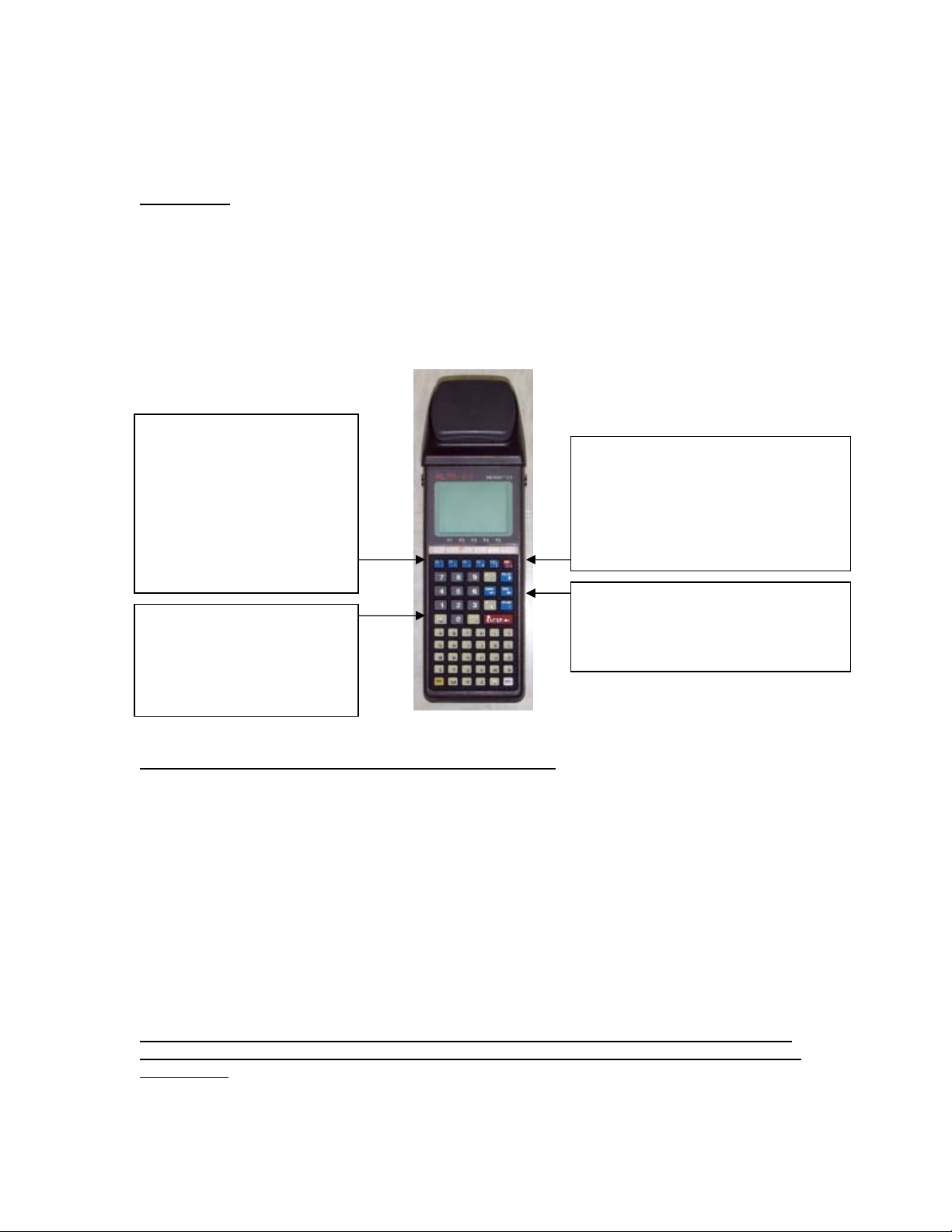
F1, F2, F3, F4, F5 function
keys. At the bottom of the
display, you are often
presented with a series of
commands. The position of
the command corresponds
to a function key. Press the
function key to use the
command.
The ESC key moves you back
one screen. If you keep
pressing it you will always
end up at the main options
screen.
ON button. If the unit is already on,
press is again from any other screen
to get to the Status report screen
(info on current location, satellites,
PDOP, battery charge status, etc).
Press the ESC button to leave this
ARROW keys. Use the up and down
arrows to move between
options/fields. Use the left and
right arrows to change the option.
Explanation of the Status codes in the upper right corner
It is important to observe the status messages in the upper right of the screen.
WAIT The unit is busy and will not respond immediately to your commands.
ACQ The receiver is acquiring signals from one or more satellites.
TRK The receiver is tracking at least one satellite.
For the following 4 digit codes, the fourth number (#) always represents the current PDOP. A
PDOP of 4.4 will appear as the number 5 (it rounds up).
N2D# The receiver is collecting data from ≥ 3 satellites, and can provide a 2D coord inate.
N3D# The receiver is collecting data from ≥ 4 satellites, and can provide a 3D coord inate.
F2D# The receiver is logging feature data to a file in 2D mode.
F3D# The receiver is logging feature data to a file in 3D mode.
The D will become a C when the receiver is detecting the RTCM beacon signal that it uses for
real-time differential. If the code does not say N3C# or F3C#, then you are not collecting submeter data. Also, if the PDOP is greater than 6, the receiver will not log sub-meter data.
1
Page 2

Before you leave
1. Check the status of the Alto batteries:
4 Turn the Alto ON.
4 Press the ON button a second time (may take a moment).
4 The % charge status of the two batteries is displayed on the screen.
4 As long as the two percentages add up to more than 40%, you will be fine. If you are
going out for a full day the two percentages should add up to at least 100%.
2. If you are collecting real-time differential data, make sure you have the backpack. It is
highly advisable to take the unit out to the sundial and make sure you are able to acquire
the real-time sub-meter corrections (see below for detailed instructions).
How to check the battery power in the Alto-G12
1. Press the ON button. Wait for a few seconds while it initializes.
2. Press the ON button again. If nothing seems to happen, wait a few more seconds.
The battery status is listed as:
BATT PACK 1(%): 54
BATT PACK 2(5): 58
(100 % = a full charge).
3. Press the ESC key to go back to the main menu.
4. Press F1 to turn the Alto off.
How to check the battery in the backpack
You can’t. If the battery is low, you will not get sub-meter locations because the receiver in
the backpack will not work. The symptom of a low backpack battery is that the units will not
detect any satellites, and the status indicator (in the top-right of the screen) will just say ACQ.
The battery should be fully charged before you check it out. If you are just using one or two
units, I recommend checking out a spare backpack battery too (we have 10 spare).
If the battery is connected, it is being drained. BE CERTAIN THAT THE BATTERY IS
DISCONNECTED WHILE YOU ARE NOT USING IT.
Check the Setup parameters on the Alto-G12
1. Press the ON button. Wait for a few seconds while it initializes.
2. At the Main Menu, use the ↑/↓ keys to select “Setup” and press ENTER.
3. Use the ↑/↓ keys to select “Datum/Coord. System.” Press ENTER.
4. Check the DATUM is WGS84, and the COORD is your preferred coordinate system: either
LLA (Lat/Long), SPC
1
(State Plane Coordinates) or UTM (Universal Transverse Mercator). If
you don’t know what you need, use LLA.
5. Press F4 (SAVE).
6. Advanced users may also want to check the setup options under “Receiver”. Of particular
importance is the PDOP setting, which represents the maximum allowable PDOP. Ideally
this should be set to 6, but if you are having trouble acquiring points, you can try setting it
to 7. Never set it higher than 8!
[NOTE: see pages 29-28 of the instruction manual for detailed setup instructions.]
1
If you select SPC, you must also define the STATE.
2
Page 3
USING THE ALTO-G12
R
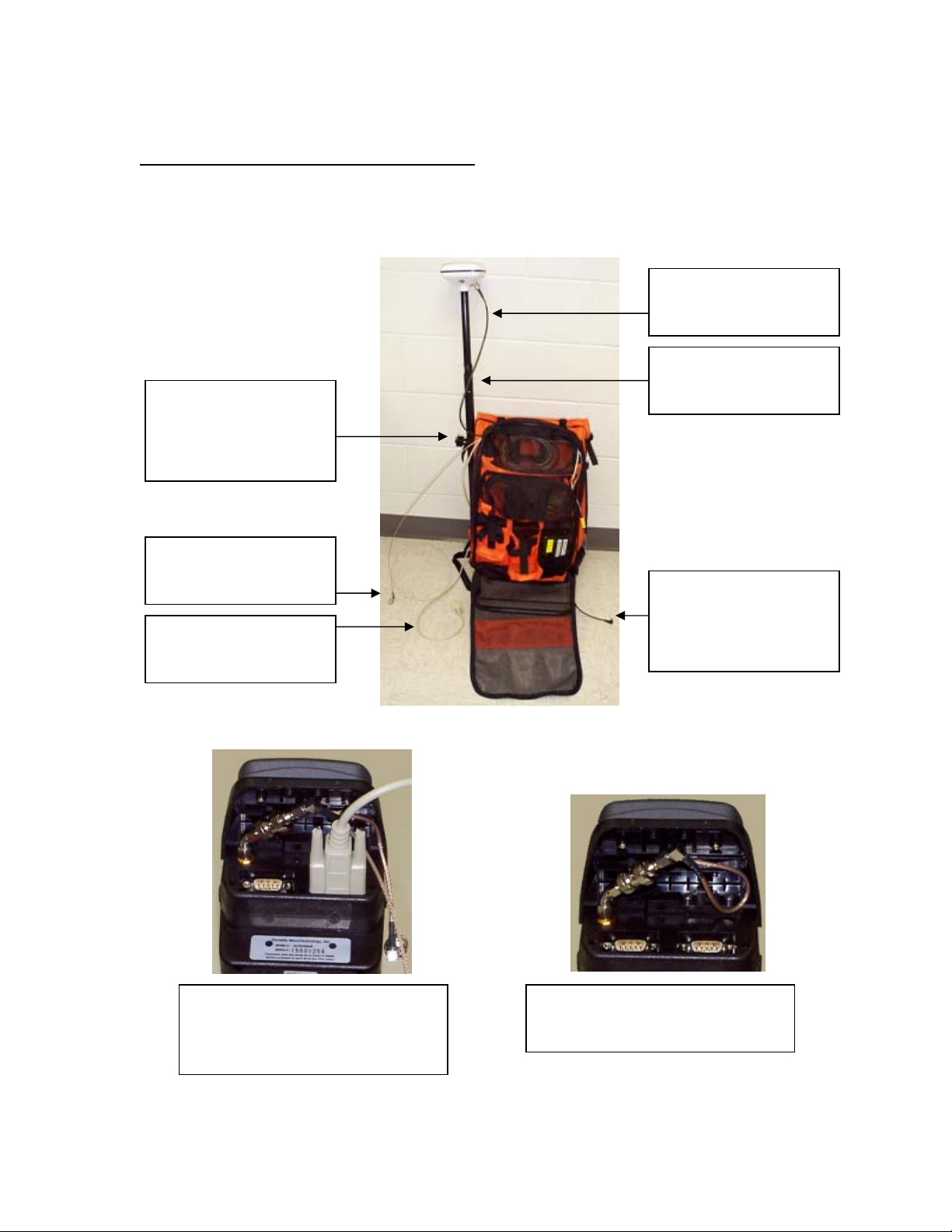
To hook up the real-time differential receiver
There are 4 cables you need to hook up. (Please try not to let the cables touch the ground as
you are hooking them up.)
Antenna cable (black),
must be attached to
white antenna.
aise the antenna pole
so that it is above the
Three cables emerge
level of your head.
from the top of the
backpack, two of which
come over your left
shoulder.
Antenna cable (brown),
attaches at the top of
the Alto-G12.
Power cable (black),
must be plugged into a
COM port cable (beige),
attaches to COM2 on
top of the Alto-G12.
battery. Unzip the
backpack to access this
cable.
For real-time, sub-meter
locations, attach the COM port
cable to COM2, and the antenna
To use the Alto-G12 without the
real-time differential, use the
built-in antenna as shown.
cable to the connector as shown.
3
Page 4

To see the coordinates of your current location, without saving them
When the unit is ON, press the ON button again to get to the STATUS screen. Your coordinates
are displayed.
Collecting data and saving to a file
Data is collected and organized into “jobs” and “features”. A job file can contain many
features. The job file might represent an entire working day of collecting points, and the
features might be locations of trees (points), sidewalks (lines), parking lots (areas).
1. From the Main Menu, select “Collect Data” and press Enter.
2. On the JOB DATA screen you can take the defaults
2
. Press F1 (GO).
3. A default file name will be displayed. Accept it by pressing ENTER or give it your own
name and press ENTER.
4. On the FEATURE INFO screen, you must enter a feature name (e.g. TREES, TRAILS, Etc.)
and define the following:
4 Feature type: Point, Line or Area.
4 Feature ID: This is OPTIONAL it will sequence automatically (e.g. TREES001,
TREES002…).
4 Logging mode: Static (for Points) or Dynamic (for Lines and Areas)
4 Intvl/session: In dynamic mode, this represents the interval between successive points
collected. In static mode, the represents the length of time to collect data for.
5. Press F5 (CONFIRM)
6. On the FEATURING screen you may manually enter as many ATTRIBUTES and
corresponding VALUES for your features as you wish (A reasonable ATTRIBUTE for TREES
may be SPECIES with a VALUE of OAK for instance).
7. On the FEATURING screen, press F4 (STORE) to begin collecting data.
• For Points the screen will automatically return to the FEATURING screen after the
point has been collected and stored. Move to your next point, change any
attribute values if needed and press F4 (STORE) to begin collecting the next point
and so on.
• For Lines and Areas, once you press F4 (STORE) to begin collecting data, start
moving to collect your feature, when you have reached the end, press F5 (END) to
stop collecting the feature, press F5 (YES) again, to verify you want to stop. You
will automatically return to the FEATURING screen where you can begin collecting
the next feature.
8. To change the Feature Type (e.g. to change from collecting points to lines), from the
FEATURING screen, press F2 (NEW FT) which returns you to the FEATURE INFO screen.
Redefine your info as in #4 above and proceed.
9. To finish, press ESC repeatedly to return to the Main Menu then turn the unit off.
At any time during this process you can press the ON button to see the Status screen. Press the
ESC key to get back to the screen you were on.
2
If you wish to add to an existing Job file, use the ↑/↓ keys to get to the Job File option, and the ←/→
keys to select the job file. Then press F1 (GO).
4
Page 5

Downloading the data to a PC
You will need to find a computer with the “PC-GPS 3.7” software on it (which may also be
labeled “Alto-G12 GPS” depending on who installed the software). All the lab computers in the
ACL and at Treehaven should have it.
You will also need a black, coiled cable with a COM port connection at both ends. Connect one
end to COM port 1 (sometimes COM port A) on the computer. Connect the other end to COM
port 1 at the top of the unit.
Receiving files from the CMT Alto-G12 GPS data collector in "Automatic" mode
Use this procedure to transfer Job files (*.FTR, *.RAW, *.DEF), Feature List files (*.FBR), Route
files (.PAT), Waypoint files (.WPT), Base files (*.DIF) , Almanac files (ALM.*) or User-defined
Coordinate System files (USER_COR.SYS and USER_DAT.SYS) from a CMT GPS data collector in
"Automatic" mode.
Please Note: PC-Mapper does not make use of Waypoint Files.
On the CMT GPS data collector:
1. Connect your data transfer cable from COM1 on the data collector to a serial port on your
PC.
2. From the Main Menu, highlight Transfer Data and press the Enter key.
In PC-GPS:
1. From the GPS menu, click Transfer.
2. (Optional) Click the Change Directory button to choose a different directory for the
incoming files.
5
Page 6

3. (If necessary) Click the type of file you wish to transfer in the File Type: list. All files on
your CMT GPS data collector of the selected type will be displayed.
4. Click the files you wish to receive or click the Select All button to receive all files listed.
5. Click the Receive button. You will see activity on both the computer screen and the GPS
screen.
6. When file transfer is complete, click the OK button OR if you are transferring Job files, you
will be given the option to open the files, go directly to differential correction or transfer
additional files.
On the CMT GPS data collector:
Press F5 (QUIT) to return to the Main Menu if it does not return automatically.
[Troubleshooting: If you see a “percent done” screen on the GPS unit, but nothing seems to happen, you
probably have either i) connected the cable to the wrong COM ports. Press the ESC key to quit the file
transfer, then connect to a different port and try again.]
The unit automatically transfers the almanac at the end of every transfer session. You may be
asked whether you want to overwrite ALM.ASH. It is always acceptable to overwrite it.
Converting your data to ArcView shapefiles
1. In the PC-GPS 3.7 software, go to File, Open, and select the job file (*.ftr) that you just
transferred. If you have multiple features contained in a single job file (as will usually be
the case) the software will load them as separate themes.
2. Select your coordinate system. The bottom right of the screen will show you what the
current coordinate system is (i.e. the coordinate system the data was collected in). Most
Wisconsin data is in the WTM83/91 coordinate system, so if you want your GPS locations to
‘line up’ with other data in ArcView, you must change the coordinate system: Go to Map >
Coordinate System, select User Defined, and choose WTM83/91.
3
Make sure that the ZONE
= Wisconsin and that UNIT = Meters. If it does not, change it then press OK.
3. From the drop down menu on the main screen of the
PC-GPS software (see right), select Shape File. Then
press the Export button:
4. Use the check mark boxes on the next screen to
identify which themes you wish to export and press
OK. It will export the shape file to the same folder
that contains the job file.
5. You can now close the PC-GPS software, open ArcView and load the themes you just
exported.
3
If WTM83 is not listed on your computer, you will need to define it yourself. Click on Edit Coordinate
System. Coordinate System Name: WTM83. Zone Name: WI. Projection: Transverse Mercator. Datum:
WGS84. The parameters are:
Central meridian: 090
False northing: -4480000
False easting: 520000
Lat of false origin: 00
Scale factor: 0.9996
o
00’00.0000”W
o
00’00.0000”N
6
Page 7

Advanced Techniques
Creating Data Dictionaries
Data dictionaries allow you to attach attribute data to GPS points, lines, or areas. The
dictionaries must be designed and created using the PC-GPS software, and then uploaded to
the units. Dictionaries increase the efficiency of data collection and reduce the risk of
associating a location with the wrong attribute data.
A. Create a feature list.
Start the PC-GPS 3.62d software. Go to the GPS menu, then Feature List. A window will
appear that allows you to either i) open an existing feature list (*.fbr) or ii) create a new
feature list (type in a filename to create and press OK).
Attribute data are modeled using Features, Attributes and Values. The Feature is the general
descriptive term: e.g. Tree. A tree is characterized by various Attributes: Species, DBH,
Height, etc. Each attribute has a specific value. If you know the range of possible values, you
can create a list that users can easily select the correct choice from. If the range of possible
values is too large to accommodate, or you are measuring precise numbers, you just leave the
Values field blank and the user can type in the value manually at the time of collection.
Click on a blue box and start
typing to fill in a field. Remember
to keep your words short (e.g. 20
letters max).
Use the Insert button to add more
lines (you must fill in the first line
before it will allow you to insert
more).
See pages 66-69 in the “PC-GPS
Reference Guide” for detailed
instructions.
Press OK when you are finished.
Uploading the data dictionary to the Alto-G12
B.
Connect the Alto-G12 to the PC using the black-coiled cable as described above (you may wish
to refer to the section “Setting Up the COM Port”). Turn the unit ON, then F4 (XFER), F4
(RECV). A status screen will appear that says WAITING.
In the PC-GPS software on your PC, select GPS, Transfer, Send. Change the file type to Feature
List (*.fbr). Select the file you wish to transfer, and press OK. If successful, you will see
activity on both screens. If it seems to do nothing, then you likely have a connection problem
(see the section “To download the data you have collected” for tips on troubleshooting).
[Note: use the ESC key to force the unit to exit out of transfer mode if you have a connection problem.]
7
Page 8

C.
Collecting data using a Feature List
1. From the Main Menu select Collect Data and press enter.
2. On the Job Data screen, use the ↑/↓ keys to select Feature List, and use the ←/→ keys to
change the selected feature list to the one you transferred. Press F1 (GO).
3. Accept the default File Name (press Enter).
4. Use the ↑/↓ keys to select the feature type from the list. Press Enter.
5. Fill in the Value field for each of the attributes in the list. If you are presented with a list
of options, use the ↑/↓ keys to select the correct option and press Enter. If there is no
list, use the keypad to type in the attribute value and press Enter.
6. When you have completed all the attributes, you will be able to press F4 (STORE) to
continue (it will start collecting the GPS data).
8
 Loading...