

Page 1

Digital AlphaStation™ 255 Family
User Information
Order Number: EK-VLLXA-UI. B01
Digital Equipment Corporation
Maynard, Massachusetts
Page 2

March 1996
The information in this document is subject to change without notice and should not be construed as a commitment
by Digital Equipment Corporation.
Digital Equipment Corporation assumes no responsibility for any errors that might appear in this document.
The software, if any, described in this document is furnished under a license and may be used or copied only in
accordance with the terms of such license. No responsibility is assumed for the use or reliability of software or
equipment that is not supplied by Digital Equipment Corporation or its affiliated companies.
Restricted Rights: Use, duplication, or disclosure by the U.S. Government is subject to restrictions as set forth in
subparagraph (c) (1) (ii) of the Rights in Technical Data and Computer Software clause at DFARS 252.227-7013.
Copyright 1996 Digital Equipment Corporation.
All Rights Reserved.
The following are trademarks of Digital Equipment Corporation:
AlphaGeneration, AlphaStation, DEC, Digital, OpenVMS, ThinWire, and the DIGITAL logo.
The following are third-party trademarks:
Microsoft and Windows NT are registered trademarks of Microsoft Corporation.
UNIX is a registered trademark in the United States and other countries licensed exclusively through X/Open
Company Ltd.
All other trademarks or registered trademarks are the property of their respective holders.
This document was produced with Microsoft Word for Windows, V6.0.
Page 3

FCC Information - Class B
This equipment has been tested and found to comply with the limits for a Class B digital device, pursuant to Part 15
of the FCC rules. These limits are designed to provide reasonable protection against harmful interference in a
residential installation.
Any changes or modifications made to this equipment may void the user's authority to operate this equipment.
This equipment generates, uses, and can radiate radio frequency energy and, if not installed and used in accordance
with the instructions, may cause harmful interference to radio communications. However, there is no guarantee
that interference will not occur in a particular installation. If this equipment does cause harmful interference to
radio or television reception, which can be determined by turning the equipment off and on, the user is encouraged
to try to correct the interference by one or more of the following measures:
•
•
•
•
The user may find the following booklet prepared by the Federal Communications Commission helpful: How to
Identify and Resolve Radio-TV Interference Problems. This booklet is available from the U.S. Government Printing
Office, Washington, D.C., 20402. Stock No. 004-00398-5.
All external cables connecting to this basic unit need to be shielded. For cables connecting to option boards, see
the option manual or installation instructions.
This digital apparatus does not exceed the Class B limits for radio noise emissions set out in the radio interference
regulations of the Canadian Department of Communications.
Reorient or relocate the receiving antenna
Increase the separation between the equipment and receiver
Connect the equipment into an outlet on a circuit different from that to which the receiver is connected
Consult the dealer or an experienced radio/TV technician for help
Page 4

Page 5

Preface
1 Getting Started
Introduction...........................................................................................................1-1
Before Starting Your System................................................................................. 1-2
Posture and Work Habits................................................................................1-2
Identifying the Correct AC Power Cord.......................................................... 1-5
Installing Your System.......................................................................................... 1-6
Connecting System Parts................................................................................1-7
Network Connection....................................................................................... 1-9
Starting Your System ............................................................................................ 1-9
Preloaded Operating System Software..........................................................1-10
Microsoft Windows NT Workstation..................................................... 1-10
Digital UNIX......................................................................................... 1-11
OpenVMS Alpha................................................................................... 1-11
Switching Console Firmware........................................................................ 1-11
If No Operating System Is Installed.............................................................. 1-11
Turning Off Your System.................................................................................... 1-12
Computer Security .............................................................................................. 1-13
Optional Lock .............................................................................................. 1-13
Passwords.....................................................................................................1-13
Contents
2 System Overview
Introduction...........................................................................................................2–1
Energy Management .............................................................................................2–1
System Features....................................................................................................2–1
v
Page 6

Contents
PCI Architecture ............................................................................................2–2
SCSI Controller..............................................................................................2–2
System Front View................................................................................................2–3
System Rear View.................................................................................................2–4
System Unit Components......................................................................................2–6
Motherboard .........................................................................................................2–8
Keyboard ............................................................................................................2–10
3 Configuring Your System
Introduction ..........................................................................................................3–1
Configuring with AlphaBIOS Firmware................................................................3–1
Starting AlphaBIOS .......................................................................................3–1
Booting the System........................................................................................3–2
AlphaBIOS Setup...........................................................................................3–3
Displaying Your Configuration................................................................3–4
Setting Up the Hard Disks.......................................................................3–5
CMOS Setup Tasks .................................................................................3–6
Advanced CMOS Setup...........................................................................3–8
Utilities ...................................................................................................3–9
Configuring with SRM Firmware........................................................................3–11
Introduction..................................................................................................3–11
Conventions.................................................................................................3–11
Booting the System......................................................................................3–13
Boot Command Examples.....................................................................3–14
Setting and Showing Environment Variables................................................3–14
Set Command........................................................................................3–14
Set Command Examples........................................................................3–15
Show Command....................................................................................3–16
Show Command Examples....................................................................3–17
Environment Variables..........................................................................3–18
Adding ISA Bus Devices..............................................................................3–19
ISA Configuration Utility......................................................................3–19
ICONFIG Utility ...................................................................................3–20
ISACFG Utility Command Format........................................................3–21
Adding ISA Options to OpenVMS and Digital UNIX Systems ..............3–23
ISACFG Command Examples...............................................................3–23
vi
Page 7

4 Installing System Options
Introduction...........................................................................................................4–1
Removing the Top Cover and Side Panel ..............................................................4–2
Removing Front Door ...........................................................................................4–4
Adding Memory Modules......................................................................................4–5
Removing the Floppy Drive Tray Assembly...................................................4–6
Installing Expansion Boards..................................................................................4–7
Installing Storage Devices...................................................................................4–10
Preparing for SCSI Device Installation.........................................................4–10
SCSI Addresses (SCSI IDs)...................................................................4–10
SCSI Bus Length................................................................................... 4–11
SCSI Termination..................................................................................4–11
Installing Optional Internal SCSI Storage Devices........................................4–12
Installing SCSI Disk Drives...................................................................4–12
Installing Drives in the Lower-Right-Side Bracket.................................4–14
Installing a Drive in the Floppy Bracket ................................................4–16
Installing External Options..................................................................................4–17
Cabling for a Printer or Other Parallel Device ..............................................4–17
External SCSI Options..................................................................................4–17
Internal Cable Layout...................................................................................4–18
Replacing the Battery.......................................................................................... 4–23
Replacing the Left-Side Panel and Top Cover.....................................................4–25
Contents
5 Troubleshooting
Introduction...........................................................................................................5–1
Initial Troubleshooting..........................................................................................5–1
Equipment Log .....................................................................................................5–2
General Troubleshooting.......................................................................................5–2
Error Beep Codes................................................................................................5–10
Diagnostic LED ..................................................................................................5–10
vii
Page 8

Contents
A System Care
B Technical Specifications
C Device Mapping
D Updating System Firmware
E Starting an Operating System Installation
F Equipment Log
Index
FIGURES
Figure 1–1: AlphaStation 255 System................................................................. 1-1
Figure 1–2: Recommendations for Posture and Work Habits............................... 1-3
Figure 1–3: System Airflow................................................................................ 1-6
Figure 1–4: Voltage Selector Switch................................................................... 1-7
Figure 1–5: Connecting Cables and Power Cords............................................... 1-8
Figure 1–6: Starting Your System...................................................................... 1-9
Figure 2–1: Front View of System......................................................................2–3
Figure 2–2: Rear Connectors..............................................................................2–4
Figure 2–3: System Unit Components................................................................2–6
Figure 2–4: Motherboard Components...............................................................2–8
Figure 2–5: Keyboard ...................................................................................... 2–10
Figure 3–1: AlphaBIOS Boot Screen..................................................................3–2
Figure 3–2: AlphaBIOS Setup Screen ................................................................3–3
Figure 3–3: Display System Configuration Screen .............................................3–4
Figure 3–4: Hard Disk Setup Screen...................................................................3–5
Figure 3–5: CMOS Setup Screen........................................................................3–6
Figure 3–6: Advanced CMOS Setup Screen.......................................................3–8
Figure 3–7: Operating System Selection...........................................................3–10
viii
Page 9

Figure 4–1: Unlocking and Removing Top Cover and Side Panel.......................4–3
Figure 4–2: Front Door Removal........................................................................4–4
Figure 4–3: Memory Installation........................................................................4–5
Figure 4–4: Removing Floppy Drive Tray Assembly..........................................4–6
Figure 4–5: Installing an Expansion Board.........................................................4–8
Figure 4–6: Inserting an Expansion Board into the Riser Slot.............................4–9
Figure 4–7: Removing the CD-ROM Drive Bracket......................................... 4–13
Figure 4–8: Removing the Drive Tray..............................................................4–14
Figure 4–9: Installing Drives in the Right-Side Bracket....................................4–15
Figure 4–10: Installing a Drive in the Floppy Bracket........................................4–16
Figure 4–11: Cabling for Printer or Other Parallel Device..................................4–17
Figure 4–12: Power Supply Cable Configuration................................................4–19
Figure 4–13: SCSI Cable Configuration.............................................................4–20
Figure 4–14: FDC Cable Configuration..............................................................4–21
Figure 4–15: MAU and Audio Cable Layout......................................................4–22
Figure 4–16: Replacing the Battery....................................................................4–24
Figure 4–17: Replacing the Left-Side Panel and Top Cover............................... 4–25
Figure 4–18: Using the Optional Kensington Lock.............................................4–26
Figure A–1: Cleaning Your Mouse.....................................................................A–2
Figure B–1: Motherboard Switch and Jumper Locations .................................. B–10
Contents
TABLES
Table 1–1: Recommendations for Posture and Work Habits............................... 1-3
Table 1–2: Operating System Shutdown........................................................... 1-12
Table 2–1: Front Components............................................................................2–3
Table 2–2: Rear Connectors...............................................................................2–4
Table 2–3: System Unit Components .................................................................2–7
Table 2–4: Motherboard Components.................................................................2–9
Table 2–5: Key Groups and Functions..............................................................2–10
Table 3–1: SRM Conventions...........................................................................3–11
Table 3–2: SRM Special Characters.................................................................3–12
Table 3–3: SRM Boot Command .....................................................................3–13
Table 3–4: Boot Command Examples..............................................................3–14
Table 3–5: SRM Set Command........................................................................3–15
Table 3–6: SRM Set Command Examples........................................................3–15
Table 3–7: SRM Show Command....................................................................3–16
Table 3–8: SRM Show Command Examples....................................................3–17
Table 3-9: SRM Environment Variables..........................................................3–18
Table 3–10: SRM ISACFG Command................................................................3–22
Table 3–11: Adding ISA Bus Options with the SRM Firmware..........................3–23
Table 4–1: Selecting a SCSI Address ...............................................................4–10
ix
Page 10

Contents
Table 4–2: Power Supply Cable Configuration.................................................4–19
Table 4–3: SCSI Cable Configuration.............................................................. 4–20
Table 4–4: FDC Cable Configuration............................................................... 4–21
Table 4–5: MAU and Audio Cable Layout.......................................................4–22
Table 5–1: System Troubleshooting...................................................................5–2
Table 5–2: Disk Drive Troubleshooting .............................................................5–8
Table 5–3: Audio Troubleshooting.....................................................................5–8
Table 5–4: Monitor Troubleshooting..................................................................5–9
Table 5–5: Error Beep Codes...........................................................................5–10
Table B–1: Processor Features..........................................................................B–2
Table B–2: System Specifications.....................................................................B–2
Table B–3: System Dimensions.........................................................................B–2
Table B–4: System Environmental Specifications............................................. B–3
Table B–5: Acoustics: Preliminary Declared Values per ISO 9296 and ISO 7779B–3
Table B–6: Bidirectional Parallel Port Pinouts..................................................B–4
Table B–7: 9-Pin Serial Port Pinouts.................................................................B–5
Table B–8: OpenVMS Port Mapping ................................................................ B–5
Table B–9: Keyboard and Mouse Connector Pinouts.........................................B–6
Table B–10: SCSI Port Pinouts ...........................................................................B–7
Table B–11: System Input Power Requirements..................................................B–8
Table B–12: System Output Power Specifications...............................................B–8
Table B–13: Motherboard Switch Settings........................................................B–11
Table B–14: Motherboard Jumper Settings........................................................B–13
Table C–1: I/O Address Map.............................................................................C–1
Table C–2: Default System Interrupt Assignments............................................ C–2
Table C–3: DMA Channel Assignments............................................................C–3
Table C–4: SCSI ID Assignments .....................................................................C–4
Table E–1: Starting a Windows NT Workstation Installation............................ E–3
Table E–2: Setting Up Partitions for a Windows NT Installation....................... E–5
Table E–3: Starting a Digital UNIX Installation................................................ E–6
Table E–4: Starting an OpenVMS Installation................................................... E–7
Table F–1: Hardware Components.....................................................................F–2
Table F–2: ISA Equipment Configuration..........................................................F–3
Table F–3: SCSI Addresses................................................................................F–3
Table F–4: Hardware Configuration...................................................................F–4
Table F–5: Installed Software ............................................................................F–4
Table F–6: Additional Component Information..................................................F–4
x
Page 11

Welcome to the Digital AlphaStation 255 Family
This guide introduces the family of Digital AlphaStation 255 systems, the latest in the
Value-Line Engineering series of AlphaStation products.
Use this information to start, use, update, troubleshoot, and configure your Digital
AlphaStation 255 system. You can also find general system information such as console
commands and system care here.
These systems include a new power-management feature, which ensures that the system
uses significantly less power when it is idle. (Details on power-management hardware
capabilities of the family of 255 systems are available in the Digital Alphastation 255
Family Technical Information.)
Audience
If you are operating, configuring, or adding options to the Digital AlphaStation 255
system, the information included here is helpful to you.
Preface
xi
Page 12

Preface
Organization of the Information
This guide includes information on AlphaStation 255 systems. The following topics (see
the Table of Contents for a detailed listing) are covered:
• Chapter 1, Getting Started. Installing, starting, restarting, and turning off the system
• Chapter 2, System Overview. Energy-efficiency features, motherboard, keyboard,
system controls, indicators, ports, and connections
• Chapter 3, Configuring Your System. Using AlphaBIOS firmware and SRM firmware.
• Chapter 4, Installing System Options. Installing hard disk, compact disc, and tape
drives; memory; option cards; printer cable; and external SCSI cable
• Chapter 5, Troubleshooting. Possible causes and actions to solve problems.
• Appendix A, System Care. Cleaning your system, monitor, and mouse.
• Appendix B, Technical Specifications.
• Appendix C, Device Mapping. I/O addresses and interrupts.
• Appendix D, Updating System Firmware.
• Appendix E, Starting an Operating System Installation.
xii
• Appendix F, Equipment Log.
Page 13

Conventions
This guide uses the following conventions:
Example Description
c:\windows
[Enter] Square brackets surrounding text represent a key on the
[Ctrl]+[R] A plus sign indicates that you press both the keys shown at
auto_action
F
Abbreviations
This guide uses the following abbreviations:
Abbreviation Meaning
CD Compact disc.
CD-ROM Compact dis c r ead-only memory .
CPU Central processing unit.
DMA Direct memory access.
DRAM Dynamic random access memory.
DROM Diagnostic read only memory.
FDC Floppy disk controller.
flashROM Electrically erasable, rewriteable, nonvolatile memory.
GB A GB suffix to a numerical value indicates size in
IRQ Interrupt request.
ISA Industry-standard architecture.
Kb A Kb suffix to a numerical value indicates size in
KB A KB suffix to a numerical value indicates size in
Monospaced text indicates file names, path names,
directories, or screen text. Each operating system has its
own specific syntax.
keyboard.
the same time.
Italic text indicates environment variables. Italic is also
occasionally used for emphasis.
A pointing hand indicates a reference to additional
information.
gigabytes
(for example, 1 GB). A gigabyte equals 1,073,741,824 bytes.
kilobits
(for
example, 512 Kb). A kilobit equals 1024 bits.
kilobytes
(for example, 640 KB). A kilobyte equals 1024 bytes.
Preface
xiii
Page 14

Preface
Abbreviation Meaning
LED Light-emitting diode.
Mb An Mb suffix to a numerical value indicates size in megabits
(for example, 10 Mb). A megabit equals 1,048,576 bits.
MB A MB suffix to a numerical value indicates size in megabytes
(for example, 550 MB). A megabyte equals 1,048,576 bytes.
MHz Megahertz.
MAU Media adapter unit.
ns Nanoseconds.
NVRAM Nonvolatile random access memory.
PCI Peripheral component interconnect.
RISC Reduced instruction set computing.
ROM Read only memory.
SCSI Small computer system interface.
SIMM Single in-line memory modules.
SRM Digital UNIX and OpenVMS console firmware.
SROM Serial read only memory.
xiv
Page 15

Special Notices
This guide uses four kinds of notices to emphasize specific information.
________________________WARNING __________________________
A WARNING indicates the presence of a hazard that can cause personal
injury.
____________________________________________________________
________________________ CAUTION___________________________
A CAUTION indicates the presence of a hazard that can damage hardware or
corrupt software.
____________________________________________________________
__________________________NOTE ____________________________
A NOTE gives general information, such as compatibility with other products or
pointers to other information.
____________________________________________________________
Preface
__________________________ HINT_____________________________
A HINT includes suggestions to make your computing tasks easier.
____________________________________________________________
Additional Information Resources
You may wish to consult the following information resources on your Digital AlphaStation
255 system:
• Digital AlphaStation™ 255 Family Installation Information (order number
EK-VLLXA-II) presents a graphical overview of the Digital AlphaStation 255 system
installation.
• Digital AlphaStation™ 255 Family Technical Information (order number
EK-VLLXA-TI). This optional manual contains detailed technical information for
value-added resellers (VARs) and independent software vendors.
xv
Page 16

Preface
Users whose systems have the Windows NT operating system may wish to consult the
Digital AlphaBIOS User's Guide, available on the World Wide Web
(http://www.windowsnt.digital.com/support/alphabios/), for further technical details on
AlphaBIOS firmware. This online guide introduces the AlphaBIOS firmware and gives
directions on configuring, starting, updating, and troubleshooting Alpha systems.
Contact your distributor or Digital representative for other available product-related
information.
xvi
Page 17
Introduction
Your Digital AlphaStation 255 system is a high-performance system that uses the latest
microprocessor technology. The system can stand alone or function as a client in an office
network environment. This chapter describes how to start, install, restart, and turn off
your system. You can also find information here about preloaded software as well as
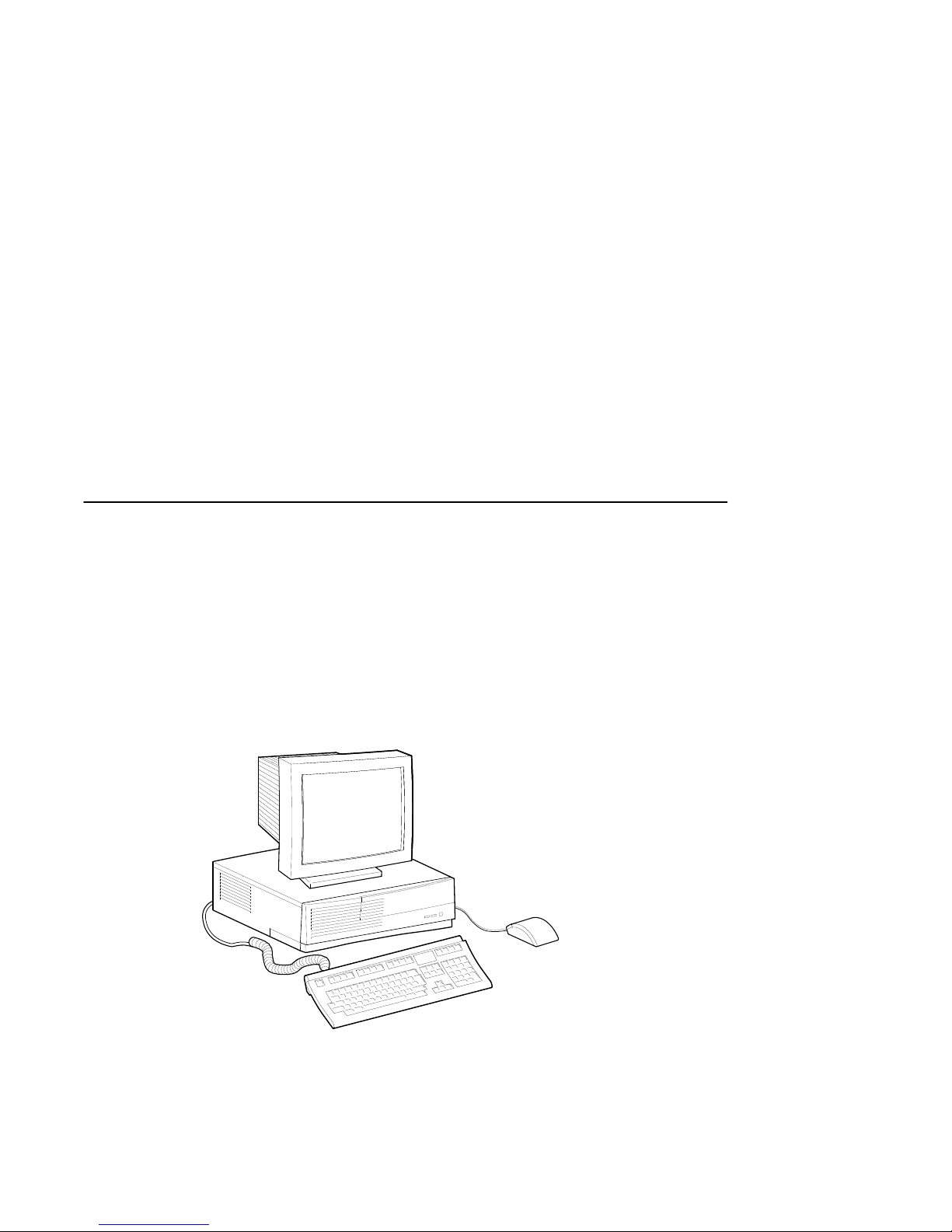
guidelines for system security. Figure 1–1 shows a typical Digital AlphaStation 255
system.
1
Getting Started
Figure 1–1: AlphaStation 255 System
1-1
Page 18

Getting Started
Before Starting Your System
Before you start your system, perform the following steps:
1. Review the information supplied with your system.
2. Select a well-ventilated site for your system near a grounded power outlet and away
from sources of excessive heat. The site also should be isolated from electric noise
(for example, spikes, sags, and surges) produced by devices such as air conditioners,
large fans, radios, and televisions.
3. Save all shipping containers and packing material for repackaging or moving the
system later.
_________________________ NOTES ____________________________
a. Do not install optional hardware or application software until you have
started your system and verified that the base system is working correctly.
b. On systems that have preloaded software, a label attached to the system unit
informs you that the licensed software has been installed. Carefully review
the software license agreement shipped with your system.
____________________________________________________________
________________________WARNING___________________________
When unpacking and moving system components, be aware that some
components (such as the system unit or monitor) may be too heavy for you
to safely lift alone. If you are doubtful about whether you can lift these
items alone, please get assistance.
____________________________________________________________
Posture and Work Habits
If you exercise poor posture while you work or if your equipment is poorly set up, certain
recent scientific articles suggest that personal injury may result. Other articles suggest that
there is no cause and effect. Because the safety of our users is a great concern to Digital
Equipment Corporation, we strongly urge that you read and follow the precautions
outlined in Figure 1–1 and Table 1–1. In addition, be sure to adjust your work space so
that you are comfortable, and change your position frequently.
1-2
Page 19
Getting Started
9
8
7
6
4
5
3
2
1
MLO-011325
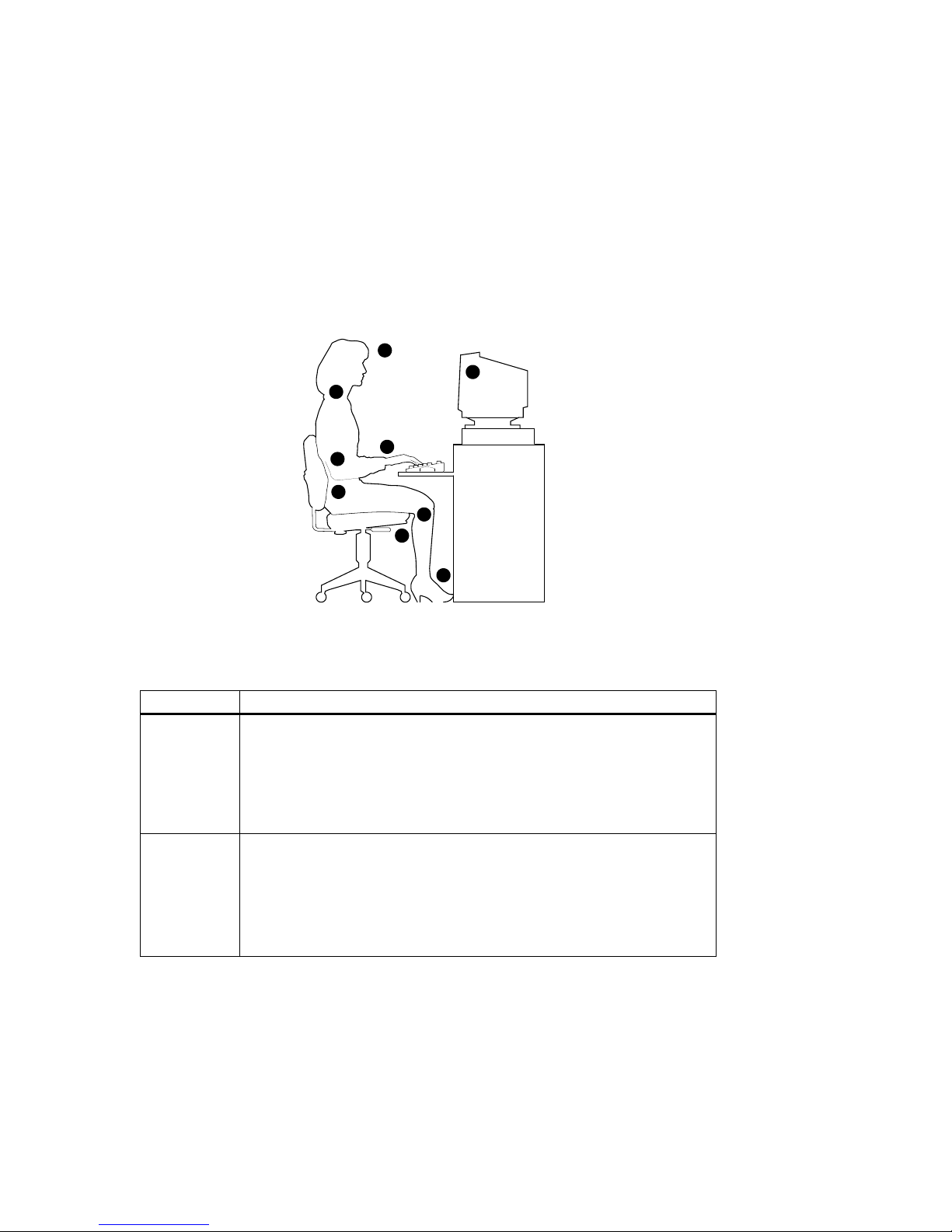
Figure 1–2: Recommendations for Posture and Work Habits
Table 1–1: Recommendations for Posture and Work Habits
Adjust To allow the following conditions
Chair 1. Feet are flat on the floor.
2. Legs are vertical and form a right angle to the floor.
3. Your thighs are horizontal, and they are not bearing weight. Keep the backs
of your knees away from the seat so you do not compress the area behind
them, which could restrict the blood flow.
4. Your upper body is erect and your lower back is supported with a backrest.
Keyboard and
Mouse
5. Your wrists are straight and do not flex more than 15 degrees. They are
supported and do not rest on sharp edges. If you use a mouse, rest your
hand on the mouse so your wrist is not on the work surface. Operate the
mouse close to your body's centerline.
6. Upper arms are straight down at your sides, and elbows are close to your
sides and support your arm weight. Forearms are at a 70- to 90-degree
angle.
1-3
Page 20

Getting Started
Table 1–1: Recommendations for Posture and Work Habits
Head 7. Avoid neck strain. Your head should incline downward, but no more than
15 to 20 degrees.
Monitor 8. No higher than the level of your eyes and at the correct distance for your
vision.
9. Avoid eye fatigue, which can be caused by glare, image quality,
uncomfortable furniture, eye height, and uncorrected vision. If you cannot
focus to read at different distances, you may need special glasses. Relax
your eyes periodically by focusing on distant objects.
Lighting Avoid direct lighting or sunlight on the screen, which causes glare and
reflections. Place lighting behind or to the side of your work area, and
distribute the lighting evenly on your work area.
Noise Keep background noise at a minimum. Background noise above 65 dBA is
tiring. Sound-absorbing materials (for example, curtains, carpeting, and
acoustic tile) can help reduce background noise.
Temperature 20 – 23 degrees C (68 - 74 degrees F)
Humidity 30% – 70%
Ventilation Provide adequate air ventilation to operate the equipment and avoid fatigue.
Work Space > 70 cm (28 inches) center to center, preferably between > 152 cm (60 inches).
(continued)
________________________WARNING___________________________
If you experience pain or discomfort while using your system, rest and
review the instructions for posture and work habits. If the pain or
discomfort continues after resuming work, discontinue use and report the
condition to your job supervisor or physician.
____________________________________________________________
1-4
Page 21

Identifying the Correct AC Power Cord
Your Digital AlphaStation 255 system came with the customer-selected AC power cord.
Because there are country-specific variations, and systems may be moved, please inspect
your power cord to ensure it is the correct one for your country or region. If you are not
sure that the supplied AC power cord is correct, contact your authorized Digital service
representative before you use it.
________________________WARNING __________________________
Do not attempt to modify or use an external 115-Volt AC power cord for
230-Volt AC input power. Modifying the power cord can cause personal
injury and severe equipment damage.
____________________________________________________________
Power cords supplied with the Digital AlphaStation 255 system meet the following
criteria:
• UL and CSA Certified cord rated for use at 250 Volts AC with a current rating that is
at least 125% of the current rating of the Digital AlphaStation 255 system. In Europe,
the cordage carries the <HAR> mark.
• The AC plug is terminated in a grounding-type male plug designed for use in the
region. It must also have marks showing certification by an agency acceptable in the
region.
Getting Started
• The connector at the computer end must be an IEC-type CEE-22 female connector.
• The cord length does not exceed 4.5 meters (14.5 feet).
1-5
Page 22
Getting Started
Installing Your System
The Digital AlphaStation 255 Family Installation Information you received with your
system graphically outlines the steps to follow in installing your system.
_______________________ CAUTIONS __________________________
1. To ensure proper cooling, verify that air can flow freely into the system front
and out the system rear and left side.
2. The system is designed to be installed horizontally on a desktop. Do not use
a stand or rack that would hold the system on its side unless it is a Digital
stand that is approved for your system.
____________________________________________________________
Check to make sure that you received all your system components. (See Appendix F,
Equipment Log, to list your equipment.) If something is missing, please contact your
distributor or Digital representative.
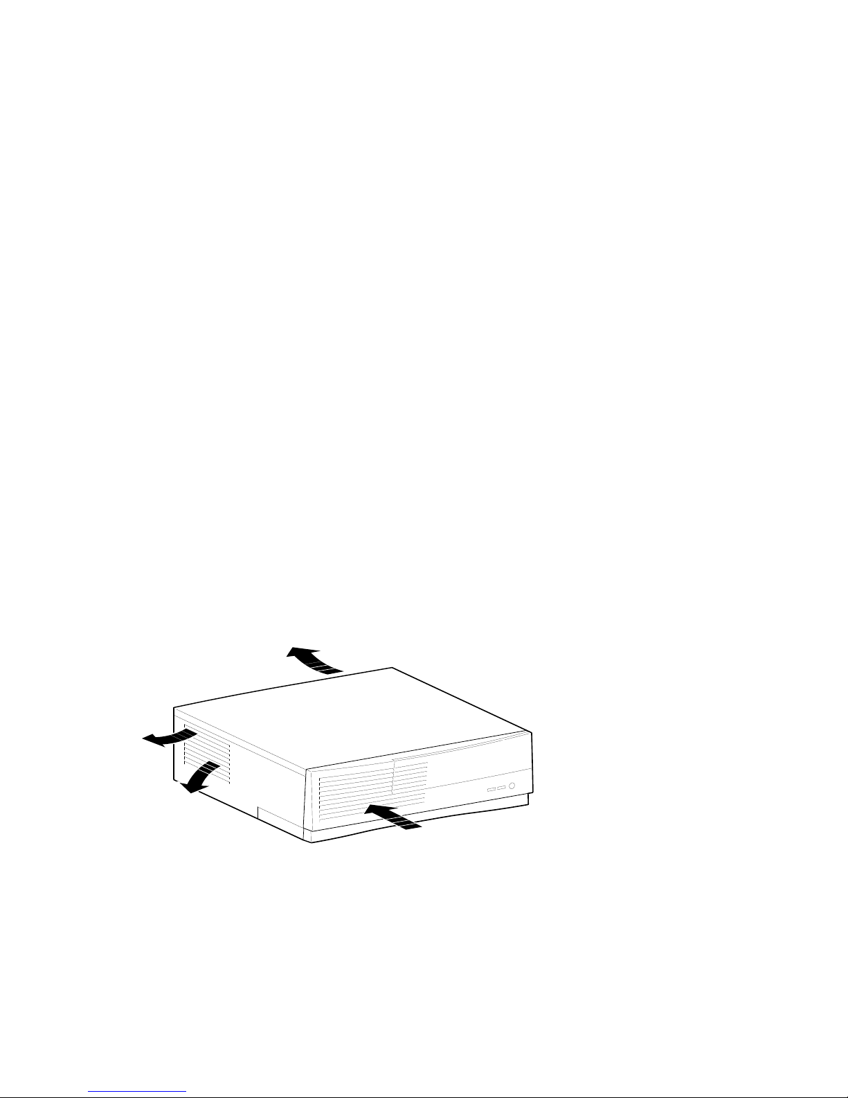
Position your system so that air can flow freely to and from the vents, as Figure 1–3
shows. Take care not to block any of the vents.
Figure 1–3: System Airflow
1-6
Page 23
Connecting System Parts
To connect the components of your Digital AlphaStation 255 system, perform the
following steps:
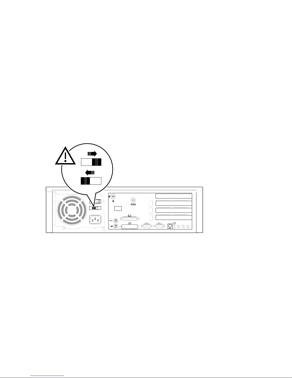
1. Confirm that the voltage selector switch matches your local voltage (either 115 Volts
or 230 Volts), as Figure 1–4 shows.
115 V
230 V
Getting Started
1
2
Figure 1–4: Voltage Selector Switch
________________________ CAUTION___________________________
Improper voltage selection can damage the system's power supply!
____________________________________________________________
2. Ensure that the power switch is in the off (O side pushed in) position.
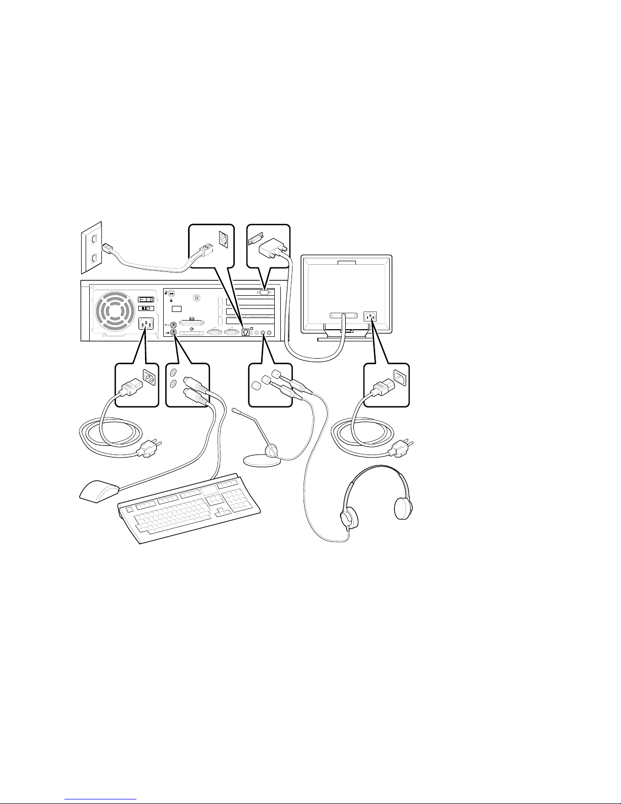
3. Connect the mouse, keyboard, video cable, microphone, headphone, and power cords
to the system components, as Figure 1–5 shows.
1-7
Page 24
Getting Started
1
2
Figure 1–5: Connecting Cables and Power Cords
4. If you have an external SCSI (small computer system interface) device or SCSI
storage box, connect the SCSI cable to the SCSI port on the rear of the system. See
the SCSI Termination section in Chapter 5, Troubleshooting.
1-8
Page 25
Network Connection
1
2
The AlphaStation 255 system has an embedded Ethernet controller with a twisted-pair
connector (RJ45) located on the rear of the system. You can order an optional media
adapter unit (MAU) (part number PBXDC-DA) if your system needs a ThinWire
connection.
Connect your system to the network using the appropriate port. If you are using the
Digital UNIX or OpenVMS operating systems, the ThinWire port is selected by default.
You can change port types by using the following SRM console commands:
>>>set ewa0_mode twisted (for the twisted pair [10Base-T] port)
>>>set ewa0_mode AUI (for the ThinWire port)
After changing the port, type >>>init or power cycle the machine.
Starting Your System
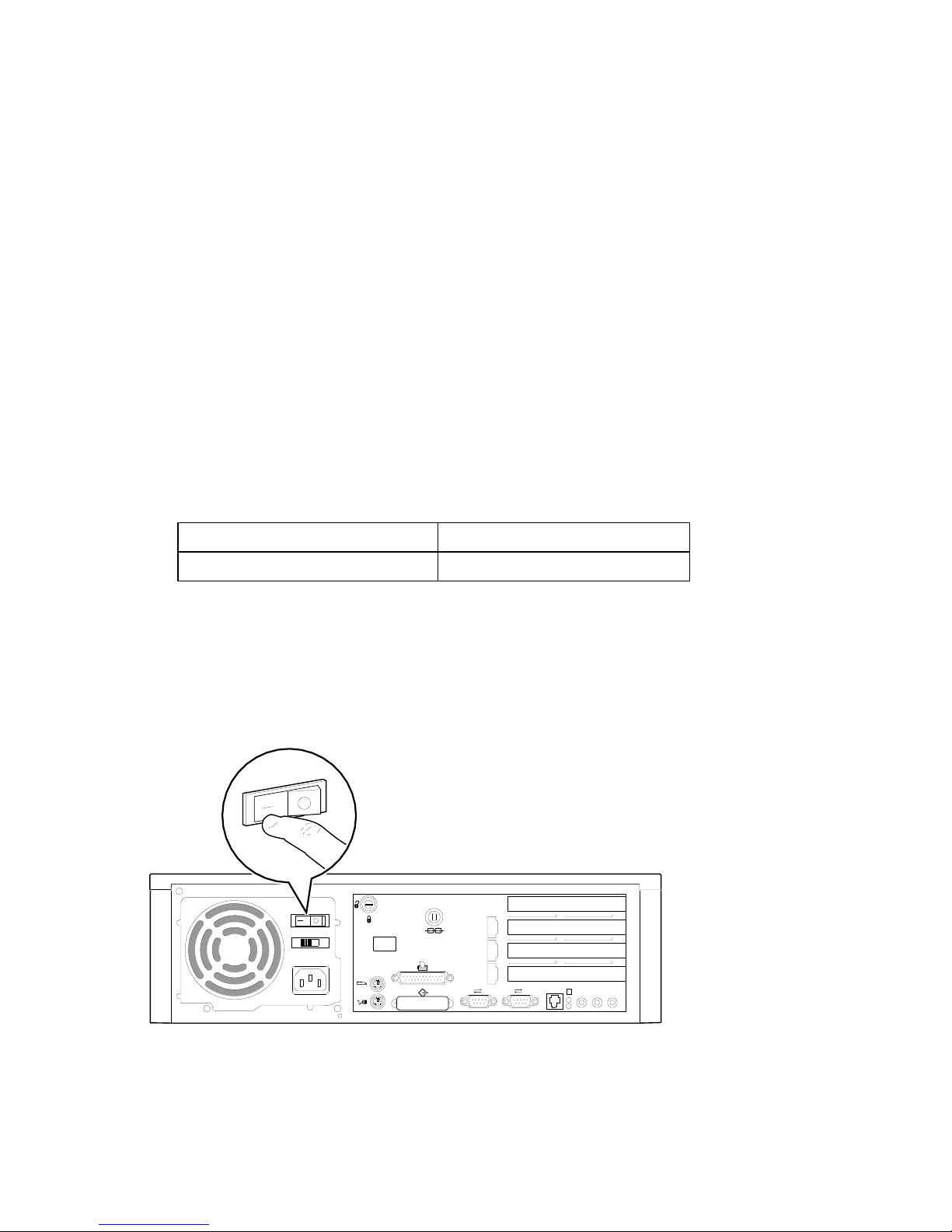
Perform the following steps, in order, to start (boot) your Digital AlphaStation 255 system:
1. Turn on the system unit power, monitor power, and any external devices. Figure 1–6
shows the location of the system unit power button.
Getting Started
Figure 1–6: Starting Your System
1-9
Page 26

Getting Started
2. After waiting for the monitor to warm up, if necessary, adjust the contrast and
brightness to obtain a readable screen display. (Refer to the information supplied with
your monitor for adjustment instructions.)
3. Allow your system to complete any power-on self tests and device initialization
messages. (This takes approximately 1 minute.) If you are using the OpenVMS or
Digital UNIX operating systems, and the auto_action environment variable is set to
"boot," the system starts as soon as the self tests have completed. If you are using the
Microsoft Windows NT Workstation operating system and autoboot is enabled, the
system starts after a countdown expires (default is 30 seconds).
Preloaded Operating System Software
If you ordered a Digital UNIX or OpenVMS version of the AlphaStation 255 system, your
operating system came preloaded. If you ordered a Microsoft Windows NT Workstation
version, the operating system is not preloaded. Disk 0 on the first SCSI bus, however, is
partitioned and formatted so that you can immediately install the operating system.
Depending on how the environment variables are set, your system shows one of the
operating system-specific displays discussed next, after the self tests have completed
successfully.
For more information on environment variables, see Chapter 3, Configuring Your
F
System.
Microsoft Windows NT Workstation
If you ordered a system with the Microsoft Windows NT Workstation operating system,
you will see the following display after system power-on and initialization:
AlphaBIOS Version 5.10
Please select the operating system to start:
Windows NT Workstation 3.51
Windows NT Workstation 3.51 (test)
Use
Press Enter to choose.
1-10
and
á
á
t
to move the highlight to your choice.
â
â
Press <F2> to enter SETUP
Page 27

If autoboot is enabled, a countdown timer [default 10 seconds] is displayed on the boot
screen. Booting occurs when the timer expires.
Digital UNIX
If you are using the Digital UNIX operating system, you see either a >>> prompt (if
auto_action is set to Halt) or the system proceeds to boot Digital UNIX (if auto_action is
set to Boot) when you power on your system.
Getting Started
F
OpenVMS Alpha
If you are using the OpenVMS Alpha (hereafter called OpenVMS) operating system, you
see either a >>> prompt (if auto_action is set to Halt) or the system proceeds to boot
OpenVMS (if auto_action is set to Boot) when you power on your system.
F
For more information, refer to your operating system documentation.
For more information, refer to your operating system documentation.
Switching Console Firmware
AlphaStation 255 console firmware resides in flashROM. The flashROM is loaded with
SRM firmware for OpenVMS and Digital UNIX systems or AlphaBIOS firmware for
Windows NT systems. You can change from SRM to AlphaBIOS or from AlphaBIOS to
SRM by using the Firmware Update Utility. (Refer to Appendix D, Updating System
Firmware.) You do not need to modify your system hardware. The operation simply reprograms the firmware flashROM.
If No Operating System Is Installed
F
If an operating system was not preloaded on your system, refer to your operating
system documentation for information on loading. (See also Appendix E, Starting
an Operating System Installation.)
1-11
Page 28

Getting Started
Turning Off Your System
Before turning off your system, save and close all open files. If you turn the system off
without saving and closing files, you might lose some or all of your work.
Perform the following steps, in order, to turn off your system:
1. Close any application data files you have open as well as any applications you have
running. Most application programs prompt you to save the information before
closing.
2. Shut down the operating system with the appropriate command from Table 1–2
below:
Table 1–2: Operating System Shutdown
Operating System Action
Microsoft Windows NT
Workstation
Digital UNIX Type the following from a superuser account:
OpenVMS Type the following from a privileged account:
From the Program Manager File Menu, choose Shutdown
press [Ctrl]+[Alt]+[Del].
Choose the OK button to confirm.
shutdown -h now
@sys$system:shutdown
or
3. Wait for the operating system to complete the shutdown process. For OpenVMS and
Digital UNIX, the SRM console prompt (>>>) is displayed. Microsoft Windows NT
Workstation displays a window indicating it is safe to turn off or restart the system.
4. Do not turn off power to your system and peripherals until the shutdown sequence has
completed.
1-12
Page 29

Computer Security
Your Digital AlphaStation 255 system includes several security-related features. See your
operation system documentation for more information on the use of these options.
Optional Lock
To provide system security, you may wish to purchase an optional Kensington lock (order
number PCP3H-AG) for your Digital AlphaStation 255 system.
Passwords
For additional security, most screen saver and pause screen displays can have password
protection enabled. Also, see the discussion of AlphaBIOS and SRM console security in
Chapter 5, Troubleshooting, of this text.
Getting Started
1-13
Page 30

Page 31

Introduction
This chapter provides an overview of the Digital AlphaStation 255 system. Topics
covered include the system's new energy-management feature as well as hardware
components, including the motherboard, PCI (peripheral component interconnect)
architecture, front panel, rear panel, system unit components, and keyboard.
Energy Management
Digital AlphaStation 255 systems include a new power-management feature. This feature
ensures that, when the system is idle, it uses significantly less power. (Details on powermanagement hardware capabilities of the family of 255 systems are available in the Digital
Alphastation 255 Family Technical Information.)
System Features
Your Digital AlphaStation 255 system uses a high-performance DECchip 21064A CPU
(central processing unit). System features include:
• Memory (DRAM): Up to 1 GB (gigabyte) DRAM
2
System Overview
• Primary cache: 16-KB instruction cache and 16-KB data cache on chip.
• Secondary cache: 1 MB.
• Data path: a 132-bit-wide (128 bits of data plus 4 bits of parity) data bus.
• PCI bus adapter with a 32-bit wide multiplexed address/data bus.
• Floppy disk controller.
• Two front-accessible I/O bays: one for 3.5 by 1-inch floppy and one for 5.25 by 1.6-
inch CD-ROM/tape drive.
2–1
Page 32

System Overview
• Bays for one or two internal hard drives: two 3.5 by 1-inch hard disk drives or one 3.5
by 1.6-inch hard disk drive and one 3.5 by 1-inch hard disk drive.
• SCSI-2 controller connects directly to the on-board PCI bus and supports up to seven
8-bit, single-ended SCSI devices (such as hard disk drives and CD-ROM drives)
running at up to ten million transfers per second (fast SCSI).
• Four I/O slots (PCI, ISA, and PCI/ISA combination) are distributed as follows: two
PCI, one combination PCI/ISA, and one ISA.
• Keyboard and mouse ports.
• Two serial ports.
• Ethernet twisted-pair connector.
• One enhanced bidirectional parallel port.
• High-performance graphics adapter.
F
Refer to Appendix B, Technical Specifications, for additional information.
PCI Architecture
Your system's PCI architecture represents the latest advances in local bus technology. The
Digital AlphaStation 255 system's PCI architecture delivers maximum performance by
providing a wider data path, greater speed, and improved expandability. PCI removes
various types of peripheral controllers from the slower ISA bus and connects them directly
to a wider, faster data path. The result is faster data transfers for devices such as SCSI
controllers and high-end video adapters—a critical advantage when you are running
graphic- and I/O-intensive software.
The PCI bridge chip (in the chipset) can be the PCI bus master, generating cycles on the
PCI bus, or it can act as a bridge between the PCI bus and memory. It can generate all
types of PCI cycles and responds to cycles initiated by devices requiring access to
memory. It performs translation of addresses supplied by other PCI devices acting as bus
masters.
The PCI interface clock speed is fixed at 33.33 Mhz, for a 30.0 ns cycle time. The
theoretical maximum instantaneous burst data rate is 132 MB/s.
The PCI includes PCI-to-ISA bridge capability that allows you to use commonly available
ISA options.
SCSI Controller
The Digital AlphaStation 255 system has a fast SCSI-2 controller that controls
up to seven SCSI peripherals such as hard disk drives, CD-ROM (compact disc
read only memory) drives, and tape drives.
2–2
Page 33

System Front View
Figure 2–1 is a front view of the system showing the location of the controls and
indicators. Table 2–1 describes these items.
Figure 2–1: Front View of System
Table 2–1: Front Components
System Overview
1 2 3 4
567
Figure
Legend
1 Floppy drive (optional) Location of 3.5-inch drive bay.
2 Floppy eject button Ejects floppy diskette when pushed.
3 CD-ROM drive 5.25-inch half-height front-accessible drive
4 CD-ROM eject button Opens the CD loading drawer.
5 Reset button This button resets the system and causes the
6 Power indicator Lights when the system is on.
7 Disk activity indicator Lights when a hard disk drive on the
Control or Indicator Function
bay.
self-test to run.
embedded SCSI controller bus is in use.
2–3
Page 34

System Overview
System Rear View
Figure 2–2 shows the rear connectors and lock. Table 2–2 lists the rear connectors and lock
and describes their functions.
1
19
3
2
5
4
1
7
6
2
14151617182021
Figure 2–2: Rear Connectors
Table 2–2: Rear Connectors
Figure
Legend
1 Power on/off switch Turns AC power on or off.
2 Key lock Locking mechanism for system cover.
3 MAU Media adapter unit (optional).
4 Enhanced bidirectional
Connector Function
Connects an industry-standard parallel printer or
parallel port
other parallel device.
13
9
8
10
12
11
2–4
Page 35

System Overview
Table 2–2. Rear Connectors
Figure
Legend
5 Kensington lock
6 Expansion slot PCI slot.
7 Expansion slot PCI slot.
8 Expansion slot Combination slot (PCI or ISA, 1/2 sized).*
9 Expansion slot Used for ISA expansion options.
10 Headphone jack Connector for the headphones or customer-
11 Microphone jack Connector for the microphone.
12 Line-in connector Brings audio signals into the system.
13 Network LEDs Green indicates that the system is linked to the
14 Twisted pair connector Connector to the embedded Ethernet controller.
15 COM port 2 Connector for communications port 2.
16 COM port 1 Connector for communications port 1.
17 SCSI port Provides the interface between the system unit and
18 Mouse connector Connects a PS/2-compatible mouse.
19 Keyboard connector Use to connect a 101- or 102-key keyboard.
20 AC power connector Connects the system to AC power.
21 Voltage selector switch Allows you to set your system to work with 115 or
Connector Function
(optional)
(continued)
Point for attaching the system to another point for
security.
supplied external speakers.
network. Yellow indicates network activity.
external SCSI devices. This connector must have
a terminator if no SCSI devices are present.
230 Volts AC power.
* The PCI/ISA combination slot cannot be used by OpenVMS users.
2–5
Page 36

System Overview
System Unit Components
Figure 2–3 shows the location of the Digital AlphaStation 255 system unit components.
Table 2–3 lists the system unit components.
3
2
1
11
10
9
8
Figure 2–3: System Unit Components
4
5
6
7
2–6
Page 37

Table 2–3: System Unit Components
System Overview
Figure
Legend
1 Media adapter unit (MAU) (optional). Provides ThinWire Ethernet
2 Memory SIMMs (up to two banks of 4 SIMMs each).
3 Power supply with internal fan.
4 Cable routing areas.
5 CD-ROM drive. Located below the CD-ROM drive is storage for one
6 Speaker.
7 3.5-inch, 1.44-MB floppy disk drive (optional).
8 Cooling fan.
9 Riser card for ISA and PCI option cards.
10 Motherboard.
11 Typical PCI option card (size varies with option).
Component
connections.
1.6-inch-high 3.5-inch hard drive or two 1-inch-high 3.5-inch hard drives.
2–7
Page 38

System Overview
Motherboard
Figure 2–4 shows the locations of the motherboard components. Table 2–4 lists the
motherboard components.
2
1
22
21
20
19
18
17
16
15
12
1314
3
10
11
Figure 2–4: Motherboard Components
4
5
8
9
6
7
2–8
Page 39

Table 2–4: Motherboard Components
System Overview
Figure
Legend
1 Power (+/- 12, +/-5 VDC) connector.
2 Power (+3.3 VDC) connector.
3 Memory banks (up to two banks of four SIMMs each).
4 Floppy disk controller (FDC) connector.
5 Internal SCSI connector.
6 Front-panel connector.
7 DECchip 21064A CPU (socketed).
8 Interrupt PAL.
9 Factory diagnostic port.
10 Factory serial ROM (if present).
11 Battery.
12 Riser card connector.
13 Ethernet ID ROM.
14 Headphone jack.
15 Microphone jack.
16 Audio line in jack.
17 Network LEDs.
18 Twisted-pair Ethernet connector.
19 COM 2 port.
20 COM 1 port.
21 External SCSI port and parallel port.
22 Mouse and keyboard connectors.
Components
2–9
Page 40

System Overview
Keyboard
Your system is equipped with a customer-selected 101-key enhanced keyboard (similar to
the one shown in Figure 2–5) that allows you to communicate with your system by
entering data or commands. (Depending upon which operating system you ordered, your
particular keyboard may vary from the one shown here.) Notice that some European
language keyboards have 102 keys. You can adjust the keyboard angle for your comfort.
The underside of the keyboard has feet that swing down and lock into place. Refer to
Table 2–5 for information on keyboard key groups and functions.
F
Refer to your operating system or application software documentation for
software-specific key functions.
1
2 3 4
Figure 2–5: Keyboard
Table 2–5: Key Groups and Functions
Figure
Legend
1 Escape key This key is program-specific. Its function
2 Function key group These keys are program-specific. Their
3 Edit key group These keys are program-specific. Their
Key, Key Group Function
is determined by the installed application
software.
functions are determined by the installed
application software.
functions are determined by the installed
application software.
MLO-012158
567
2–10
Page 41

System Overview
Table 2–5: Key Groups and Functions
Figure
Legend
4 Indicator lights Indicates whether the NumLock,
5 Numeric keypad These keys perform numeric functions and
6 Cursor control key
7 Alphanumeric key
Key, Key Group Function
CapsLock, or ScrollLock has been
activated.
software-defined functions, including
cursor control. The NumLock key allows
you to toggle between the numeric
functions and software-defined functions.
These keys control the movement of the
group
group
highlighted cursor on the monitor screen.
The keys are typewriter-specific.
(continued)
2–11
Page 42

Page 43

Configuring Your System
Introduction
This chapter shows you how to configure your AlphaStation 255 system. The firmware
used to configure your system depends the operating system being used. Systems running
the Microsoft Windows NT Workstation operating system use the AlphaBIOS firmware.
Systems running the OpenVMS or Digital UNIX operating systems use the SRM firmware.
Configuring with AlphaBIOS Firmware
AlphaBIOS firmware supports the Microsoft Windows NT Workstation operating system.
You can use AlphaBIOS firmware to perform various configuration tasks, such as:
• Selecting a copy of the Windows NT system to boot.
• Displaying system configuration information.
• Setting up the hard disk.
• Setting the date and time.
• Enabling and setting the delay for auto start.
3
• Setting or changing the AlphaBIOS password.
Starting AlphaBIOS
When the system is powered on, and the power-on self-tests (POST) sucessfully completes,
the AlphaBIOS firmware is loaded and started. AlphaBIOS performs several initialization
tasks. Among them are, initialize the keyboard and video devices, test memory, and detect
and initialize SCSI disk controllers. After the video device is initialized, subsequent steps
are displayed on the monitor in an initialization window.
When the SCSI initialization is complete, AlphaBIOS leaves the initialization window and
displays the boot screen.
3–1
Page 44

Configuring Your System
Booting the System
The system is booted from the boot screen (Figure 3–1). The boot screen lists each of the
different copies of the Windows NT operating system that have been installed on your
system. Choose the operating systems to boot and press [Enter]. Enter the AlphaBIOS
Setup program by pressing [F2].
Figure 3–1: AlphaBIOS Boot Screen
3–2
Page 45

AlphaBIOS Setup
Start the AlphaBIOS Setup program by pressing [F2] while the boot screen is displayed.
Figure 3–2 shows the AlphaBIOS Setup screen. Use the setup screen to select the desired
task. Press [Escape] to return to the boot screen.
Configuring Your System
Figure 3–2: AlphaBIOS Setup Screen
3–3
Page 46

Configuring Your System
Displaying Your Configuration
AlphaBIOS provides clear, easy-to-read display of the system configuration. The display
is organized by systemboard, memory, hard disk, PCI, SCSI, and integrated devices. From
the AlphaBIOS Setup screen, select Display System Configuration and press [Enter].
From the Display System Configuration screen, use the arrow keys to select the
configuration category you wish to view. Figure 3–3 shows the Systemboard
Configuration category.
Figure 3–3: Display System Configuration Screen
Memory Configuration
The memory configuration display shows bank size, the starting address of each bank, and
the capacity of the SIMMs in the bank.
Hard Disk Configuration
The hard disk configuration screen displays information about recognized disk drives. The
display includes the drive type and capacity as well as partition sizes and formats. The
lowest-numbered drive is displayed as drive 0, even though its SCSI ID may be 1 or
higher.
3–4
Page 47

PCI Configuration
The PCI configuration screen displays both the embedded and the slot-mounted PCI
devices. The device names and types, along with their respective revision levels, are
displayed.
SCSI Configuration
The SCSI configuration screen displays SCSI device information. The SCSI IDs, device
types (and sizes, if applicable), and a description of the devices are displayed.
Integrated Peripherals
The integrated peripherals screen display shows the addresses and IRQs of the serial and
parallel ports.
Setting Up the Hard Disks
AlphaBIOS makes it easy to format and partition hard disks on the system. Typically, you
partition and format drive 0. Using the Windows NT Disk Administrator, you can quickly
partition and format the other drives. Select Hard Disk Setup from the AlphaBIOS Setup
screen. Figure 3–4 shows the Hard Disk Setup screen.
Configuring Your System
Figure 3–4: Hard Disk Setup Screen
Press [F7] to perform an express disk setup. The express setup command partitions and
formats the selected disk in the recommended manner (6 MB FAT system partition)
__________________________NOTE ____________________________
AlphaBIOS refers to the SCSI disk with the lowest ID as Disk 0.
____________________________________________________________
3–5
Page 48

Configuring Your System
CMOS Setup Tasks
Use the CMOS setup program to configure system parameters such as the date and time,
floppy drive types and capacities, keyboard country and style, and auto start enabling and
delay. There also is an advanced CMOS setup mode used to control PCI parity checking,
memory testing, AlphaBIOS password, and SCSI termination.
To enter the CMOS Setup, select CMOS Setup from the AlphaBIOS Setup screen. Use
[Tab] to move among the fields.
Figure 3–5: CMOS Setup Screen
Date and Time
When setting the time, use the 24-hour format; for example, 10:00 p.m. should be
expressed as 22:00:00.
3–6
Page 49

Configuring Your System
Floppy Drive
AlphaBIOS supports the following drive types:
• 5.25-inch, 1.2-MB
• 3.5-inch, 1.44-MB
• 3.5-inch, 2.88-MB
Keyboard
The keyboard setting allows the use of nearly any language keyboard available. To ensure
correct character mappings, make sure that the language of your keyboard, Microsoft
Windows NT Workstation, and the keyboard-language selection in CMOS setup all match.
Auto Start and Auto Start Count
The Auto Start setting determines whether the primary operating system is automatically
started after the system is reset or power-cycled. The Auto Start Count setting is the
amount of time the boot screen is displayed before the default system is automatically
started. This delay gives you the opportunity, after resetting or power-cycling the system,
to select another operating system to start or to enter AlphaBIOS setup.
CMOS Setup Options
• Color. Pressing [F3] repeatedly cycles through the available AlphaBIOS color
schemes.
• Advanced. Pressing [F6] displays the Advanced CMOS Setup screen.
• Defaults. Pressing [F7] restores the default standard CMOS setup values without
affecting the advanced CMOS setup values.
• Discard Changes. Pressing [Escape] restores the settings that were in effect when
you started CMOS setup. This option also discards changes made in advanced CMOS
setup.
• Save Changes. Pressing [F10] saves changes made in both the standard and advanced
modes of CMOS setup.
3–7
Page 50

Configuring Your System
Advanced CMOS Setup
Enter the advanced CMOS setup screen by pressing [F6] in the CMOS Setup screen.
Figure 3–6: Advanced CMOS Setup Screen
PCI Parity Checking
This setting controls PCI parity checking at the PCI bridge chip. Parity checking is
performed if enabled and ignored if disabled. The default is disabled. Certain PCI
adapters have been known to generate bad parity on the PCI under certain loading
conditions, which results in system errors. Ensure that your specific PCI configuration will
operate correctly prior to turning on parity checking.
Extended Memory Test
Extended memory test can be enabled or disabled. When enabled, the memory test writes
and then reads several patterns of data to main memory. This testing verifies the integrity
of the memory.
Password Setup
To help maintain system security, AlphaBIOS provides two levels of password protection:
system setup and system startup. When system setup protection is enabled, you need a
password to enter the AlphaBIOS setup program. When system startup protection is
enabled, you must enter a password before system initialization will take place. Startup
password protection provides more comprehensive protection than setup password
protection because the system cannot be used until you enter the correct password.
3–8
Page 51

Utilities
Configuring Your System
__________________________NOTE ____________________________
To change the password, simply set up your password again.
____________________________________________________________
SCSI Termination
The SCSI termination feature is not necessary on the AlphaStation 255 system. External
devices are automatically detected, and termination is set appropriately.
Advanced CMOS Setup Options
• Discard changes. Pressing [Escape] restores the settings in effect when you entered
advanced CMOS setup. This does not discard changes made to standard CMOS setup.
• Save changes. Pressing [F10] saves changes you have made in advanced CMOS
setup. When exiting CMOS setup, you also must save your changes at the CMOS
setup screen for the changes to be stored permanently.
Two utilities, operating system selection and run a maintenance program, are available
from the utilities menu.
3–9
Page 52

Configuring Your System
OS Selection Setup
Each operating system selection is a set of information that describes the disk and partition
containing OSLOADER.EXE.
Figure 3–7: Operating System Selection
Running a Maintenance Program
A maintenance program, such as a RAID configuration utility, is run directly from the
AlphaBIOS utility menu.
3–10
To run a maintenance program, follow this procedure:
1. Start AlphaBIOS setup, select Utilities, select Run Maintenance Program from the
submenu, and press [Enter].
2. In the Current Partition field, select the hard-disk partition, floppy disk, or CD-ROM
drive from which to run the program. Type the program name into the Program Name
field.
Page 53

Configuring with SRM Firmware
Introduction
Systems running the OpenVMS or Digital UNIX operating systems, use the SRM
firmware. You can use the SRM firmware to perform various configuration tasks, such as:
• Booting the system.
• Setting environment variables.
• Displaying the system configuration.
• Adding ISA bus devices.
Conventions
Table 3–1 shows the conventions used in SRM firmware.
Table 3–1: SRM Conventions
Item Convention
Console prompt >>>
Maximum command length 255 characters
Multiple contiguous spaces or tabs Treated as a single space
Command abbreviations Allowed, if not ambiguous
Command qualifiers or options Prefix with a space and a dash " -"
Numbers Hexadecimal, unless otherwise specified. (Note
Configuring Your System
that registers such as R0-R31 are shown in
decimal notation.)
3–11
Page 54

Configuring Your System
Table 3–2 shows the special characters used in SRM firmware.
Table 3–2: SRM Special Characters
Character/Key(s) Function
[Return] Terminates command line input.
[ß] Backspace Deletes the previously typed character.
[Ctrl]+[A] Toggles insert/overstrike mode. (Overstrike is the default.)
[Ctrl]+[B], [á] or [â] Recalls previous commands. (The last 16 commands are stored.)
[Ctrl]+[C] Terminates the foreground process.
[Ctrl]+[D] or [ß] Moves the cursor left one position.
[Ctrl]+[E] Moves the cursor to the end of the line.
[Ctrl]+[F] or [à] Moves the cursor right one position.
[Ctrl]+[H] Moves the cursor to the beginning of the line.
[Ctrl]+[O] Suppresses/resumes (toggles) console output.
[Ctrl]+[Q] XON, Resume flow of data to the console.
[Ctrl]+[S] XOFF, Stops the flow of data to the console.
[Ctrl]+[U] Deletes the entire line.
[Ctrl]+[R] Retypes the current command line.
3–12
Page 55

Booting the System
The boot command performs the following functions:
• Initializes the processor.
• Loads a program image from the specified boot device.
• Transfers control to the loaded image.
The syntax of the boot command is:
boot [-file <filename>] [-flags <longword>[,<longword>]]
[-protocols <enet_protocol>] [-halt] [<boot_device>]
The boot command options are described in Table 3–3.
Table 3–3: SRM Boot Command
Command Option Description
-file <filename>
-flags
<longword>[,<longword>]
-protocols <enet_protocol> Specifies the Ethernet protocol(s) that will be used for a
-halt Forces the bootstrap operation to halt and invoke the
<boot_device>
Configuring Your System
Specifies the name of a file to load into the system. For
booting from Ethernet, this name is limited to 15
characters. Use the set boot_file command to set the
environment variable that specifies a default boot file.
Specifies additional information for the operating system.
For systems with OpenVMS, root number and boot flags
are specified here. For Digital UNIX systems, the
following symbolic values may be used:
i = interactive boot
s = boot to single user
a = autoboot to multiuser
Use the set boot_osflags command to set an environment
variable that specifies a default boot flag value.
network boot. Values may be set mop or set bootp.
console program after the image is loaded and the page
tables and other data structures are set up.
Specifies a device path or list of devices that the firmware
will attempt to boot. Use the set bootdef_dev command
to set an environment variable that specifies a default boot
device.
3–13
Page 56

Configuring Your System
Boot Command Examples
Table 3–4 shows boot command examples and their descriptions.
Table 3–4: Boot Command Examples
Command Description
>>>boot
>>>boot ewa0
>>>boot -file dec2.sys ewa0
>>>boot -protocol bootp ewa0
>>>boot -flags 0,1
>>>boot -halt dka0
Boots the system from the default boot
device.
Boots the system from Ethernet port ewa0.
If you are booting over a network, set
ewa0_protocols
BOOTP.
Boots the file named dec2.sys from
Ethernet port ewa0.
Boots using TCP/IP BOOTP protocol from
Ethernet port ewa0.
Boots the system from the default boot
device using flag settings 0,1.
Loads the image from disk dka0, but
remains in console mode.
ewa0_inet_init
and
to
Setting and Showing Environment Variables
Set Command
The set command is used to set or modify the value of an environment variable.
Environment variables are used to pass configuration information between the console and
the operating system.
The syntax of the set command is:
set <envar> <value> [-default] [-integer] [-string]
3–14
Page 57

Table 3–5 describes the SRM set command options.
Table 3–5: SRM Set Command
Command Option Description
<envar> The environment variable to be assigned a new value.
<value> The value that is assigned to the environment variable. It
-default Restores an environment variable to its default value.
-integer Creates an environment variable as an integer.
-string Creates an environment variable as a string.
Set Command Examples
Table 3–6 shows set command examples and their descriptions.
Table 3–6: SRM Set Command Examples
Command Description
>>>set bootdef_dev ewa0
>>>set auto_action boot
>>>set boot_osflags 0,1
>>>set foobar 5
Configuring Your System
can be either a numeric value or an ASCII string.
The default boot device is set to ewa0.
The console attempts to boot following an error, halt, or
power-up.
The default boot flags are set to 0,1.
An environment variable called foobar is created and given
a value of 5.
3–15
Page 58

Configuring Your System
Show Command
The show command displays the current value of a specified environment variable. The
show command also displays information about the system, according to the arguments
entered.
The syntax of the show command is:
show [{config, device, hwrpb, memory, pal, version,
<envar>...}]
The show command options are described in Table 3–7.
Table 3–7: SRM Show Command
Command Option Description
config Displays the current memory configuration, PCI logical
device [device name] Displays the devices and controllers in the system.
<envar> Displays the value of the environment variable specified.
error Displays error log information.
map Displays the system virtual memory map.
memory Displays the memory module configuration.
pal Displays the version of OpenVMS and OSF PALcode.
version Displays the version of the console firmware.
slots, and ISA logical slots (based on ISACFG utility input
to the configuration database).
Specifying a device name returns information on that
device only.
3–16
Page 59

Show Command Examples
Table 3–8 lists show command examples and their descriptions.
Table 3–8: SRM Show Command Examples
Command Description
>>>show device
dka0.0.0.6.0 DKA0 RZ26L 441A
dka400.4.0.6.0 DKA400 RRD43 3213
dva0.0.0.0.1 DVA0
ewa0.0.0.12.0 EWA0 08-00-2B-E2-1C-25
pka0.7.0.6.0 PKA0 SCSI Bus ID 7
>>>show memory
64 Meg of System Memory
Bank 0=32 MB (8 MB per Simm)
Starting at 0x2000000
Bank 1=32 MB (8 MB per Simm)
Starting at 0x0
Bank 2=No Memory Detected
>>>show *
(See the environment variable section.)
>>>show boot*
(See the environment variable section.)
Configuring Your System
Lists device information, such
as system designation, drive
model, or Ethernet address.
Lists system RAM, bank sizes,
and starting addresses.
Bank 2 is always unused in the
AlphaStation 255 system.
Lists all variables and their
settings.
Lists all variables beginning
with boot.
3–17
Page 60

Configuring Your System
Environment Variables
Table 3-9 shows selected environment variables and their descriptions (for a complete list,
type show * at the SRM prompt).
Table 3-9: SRM Environment Variables
Variable Description
auto_action
boot_file
boot_osflags
bootdef_dev
bus_probe_algorithm
console
control_scsi_term
ewa0_inet_init
ewa0_mode
Sets/shows the console action following an error, halt, or power-up.
The action can be
Sets/shows the file name to be used when a bootstrap requires a
filename. The default setting is null.
Sets/shows additional parameters to be passed to system software.
When using OpenVMS software, these parameters are the system
root number and boot flags. The default setting is
When using Digital UNIX software, the following parameters are
valid:
Sets/shows the default device or device list from which the system
will attempt to boot. If the system software is pre-loaded, the
variable is preset to point to the device containing the pre-loaded
software. Otherwise, the default value is null.
Selects which method the firmware uses to probe the PCI bus for
PCI devices during initialization. Possible values are
The default is new.
Sets the console output to either
controller.
Unused in the Digital AlphaStation 255 system.
Allows network booting operations. (In this case, possible values
are
Selects which Ethernet port to use:
Full Duplex, twisted-pair; BNC; Fast
controllers); or
Full Duplex). AUI is the default. (Auto-sensing is not supported.)
i
s
a
BOOTP
halt, boot
= interactive boot
= boot to single user
= autoboot to multiuser
MOP.
or
FastFD
, or
)
(for Fast Ethernet controllers that support
restart
. Halt is the default.
serial
port or the
AUI
(ThinWire);
(for Fast Ethernet
0,0
.
new
and
graphics
twisted-pair;
old.
3–18
Page 61

Configuring Your System
Table 3–9: SRM Environment Variables
Variable Description
ewa0_protocols Determines the Ethernet protocol , which can be either
BOOTP
kbd_hardware_type Selects the type of keyboard on your system. Possible values are
LK411
language The language environment variable associates language n to the
system (where n is the number of the language shown below). You
can have the system prompt you for the language using the
following command: >>>set language 0 and then
>>>init. Select the desired language. Type >>>init again,
then power cycle the system.
os_type Identifies the operating system being used on the system. Values
of
load.
pka0_fast A value of 0 sets the SCSI mode to slow (5 MB/sec); a value of
sets the SCSI mode to fast (10 MB/sec). Digital UNIX operating
system users also must edit the configuration file and rebuild the
kernel.
pci_parity This variable controls PCI parity checking at the PCI bridge chip.
Parity checking is performed if on, disabled if
on the SCSI controller revision if
Certain PCI adapters have been known to generate bad parity on
the PCI under certain loading conditions, which results in system
errors.
. MOP is the default.
PCXAL
or
OpenVMS, OSF, UNIX,
(continued)
. PCXAL is the default.
VMS
or
cause the SRM console to
sniff
. Default is off.
MOP
off
, and dependent
or
1
Ensure that your specific PCI configuration will operate correctly
prior to turning on parity checking.
tga_sync_green This variable is used to control the composite video signal for
monitors on the ZLXp controller that cannot detect the presence of
composite video or v/h signals. The possible values are:
1
2
3
Adding ISA Bus Devices
ISA Configuration Utility
ISA devices cannot be probed for configuration information by the Digital UNIX or
OpenVMS operating system. Therefore, you must enter ISA option information manually
using the ISA configuration utility. Run this utility before installing a new ISA option
– composite video for first ZLXp.
– composite video for the second ZLXp.
– composite video for the first and second ZLXp.
3–19
Page 62

Configuring Your System
module on a Digital AlphaStation 255 system running either the Digital UNIX or
OpenVMS operating system.
Two methods are available to perform ISA configuration tasks: a forms-based interface
(ICONFIG) and a command line interface (ISACFG).
ICONFIG Utility
The ICONFIG utility is a subset of the ISACFG utility. Only one type of each field (or
option) can be set (for example, one IRQ or one I/O address) in ICONFIG. Future
versions will include more functionality.
Start ICONFIG at the SRM prompt by typing >>>iconfig[Return]. The following
screen is displayed:
ISA CONFIGURATION UTILITY
Name I/O IRQ DMA Mem Length Enabled
MOUSE 60 12 Y
KBD 60 1 Y
COM1 3f8 4 Y
COM2 2f8 3 Y
LPT1 3bc 7 Y
FLOPPY 3f0 6 2 Y
HELP: Enter up to 15 char device name
KEY HELP: Arrows/TAB to move, RET once to submit entry,
RET 2nd time to exit
To add an ISA option, first enter the device's name, then move to the next field and enter
its I/O address, and so forth. For example, to add a DE205 Ethernet controller to the
database, follow these steps in response to the HELP: prompts at the bottom of the
display:
1. Enter up to 15 char device name DE200-LE [Tab]
2. Enter i/o address in hex 300 [Tab]
3. Enter IRQ channel in decimal 5 [Tab]
4. Enter dma channel in decimal [Tab]
5. Enter memory address in hex d0000 [Tab]
6. Enter length of memory in hex 10000 [Tab]
7. Enter N to disable, Y to enable Y [Return]
3–20
Page 63

When you press [Return], the entry is submitted and checked for conflicts. If conflicts
exist, a message is displayed. For example, if you entered an IRQ value of 8 instead of 5,
the following message is displayed:
ISACFG MESSAGE: ERROR: IRQ conflict with reserved IRQ values
(0,2,8,11 or 13)
If you entered a DMA value of 2 rather than nothing, the following message is displayed:
ISACFG MESSAGE: ERROR: DMA conflict with slot 0 dev 5
You can delete an entire entry by using the [Backspace] key.
ISACFG Utility Command Format
The syntax of the ISACFG command is:
isacfg [-slot <slot#>] [-dev <device#>]
[-all|-rm|-mk|-mod] [-<field> <value>] . . .
The ISACFG command options are described in Table 3–10.
Configuring Your System
3–21
Page 64

Configuring Your System
Table 3–10: SRM ISACFG Command
Command Option Description
-all Shows the entire configuration table. Overrides all other
-dev <dev#> Optional; defaults to 0 if not entered. On a multifunction or
-dmachan{0-3} <#> Allows you to specify up to four DMA (direct memory access)
-enadev <#> Allows you to specify whether an entry is enabled or disabled.
-etyp <#> Defines an entry type for this entry. The # sign can be:
-handle <string> Binds a name to the driver (up to 15 characters).
-init Initializes the configuration table to the default settings.
-iobase{0-5} <#> Specifies up to six I/O base registers (in hexadecimal) for a
-irq{0-3} <#> Allows you to assign up to four IRQ (interrupt request) channels
-membase{0-2} <#> Specifies up to three R/W ISA memory regions (in
-memlen{0-2} <#> Specifies the length corresponding to membase{0-2} (in
-mk Adds an entry into the table.
-mod Modifies an entry in the table.
-rm Deletes an entry from the table.
-rombase <#> Specifies an address for ISA BIOS ext. ROM (in hexadecimal).
-romlen <#> Specifies length of ROM (in hexadecimal).
-slot <slot#> Allows you to enter a unique slot number for each ISA adapter.
-totdev <#> Placeholder for you to keep track of the total number of devices,
commands.
multiport adapter, this specifies the device on the adapter.
channels for the device.
Disabled devices are not used in resource allocation calculations.
The possible values are:
0 - No (disabled)
1 - Yes (enabled)
0 - Causes the entry to be deleted
1 - Single option
2 - Embedded multiport device
3 - Multiport option device
particular device entry.
to the device (use decimal IRQ levels).
hexadecimal).
hexadecimal).
You may assign the numbers in any order. The slot number does
not relate to a physical ISA adapter position. Slot 0 is reserved
for the motherboard devices.
specified by the # sign, at this slot. Modify this for your own
use.
3–22
Page 65

Adding ISA Options to OpenVMS and Digital UNIX Systems
When you add a supported ISA option to an AlphaStation 255 system running the
OpenVMS or Digital UNIX operating system, perform the procedure shown in
Table 3–11.
Table 3–11: Adding ISA Bus Options with the SRM Firmware
Step Action Result or Next Step
1 Perform operating system
configuration tasks, if any. Refer
to your operating system
installation guide and release notes.
2 Shut down the system. The system is at the console prompt (
>>>isacfg options
3
>>>init
4
5 Configure the ISA option. Use the manual that came with your ISA
6 Turn off the system and install the
ISA option.
7 Turn on the system and boot. The operating system boots and sees the new
The operating system is prepared for the ISA
option.
Adds the new ISA option to the SRM console
configuration table using the appropriate
command options.
init
Typing
option to set the proper configuration.
Refer to Chapter 3, Configuring Your
System.
ISA option.
allows the changes to be used.
Configuring Your System
>>>
).
ISACFG Command Examples
This section shows examples of ISACFG commands you use to enter the DE205, audio
subsystem, and the FAX/MODEM options into the configuration database. Examples to
display, modify, and remove table entries are included as well. In some cases, there are
scripts available to issue the proper ISACFG command. Script commands are preceded by
an "add_" prefix. To continue long commands onto the next line, type a backslash (\) at
the end of the line.
type an
Always
command after doing ISACFG commands.
init
3–23
Page 66

Configuring Your System
Adding the DE205 option:
>>>add_de205
-or-
>>>isacfg -slot 1 -dev 0 -mk -handle DE200-LE -irq0 5 \
_> -iobase0 300 -membase0 d0000 -memlen0 10000 -etyp 1 -enadev 1
Enabling the audio subsystem
>>>add_sound
-or-
>>>isacfg -slot 2 -etyp 1 -mk -iobase0 530 -iobase1 388 \
_>-irq0 9 -dmachan0 0 -dmachan1 1 -handle PCXBJ -enadev 1
Disabling the audio subsystem
>>>isacfg -slot 2 -rm
Adding the FAX/MODEM option:
>>>add_fax
-or-
3–24
the following two commands:
>>>isacfg -mod -slot 0 -dev 3 -enadev 0
>>>isacfg -slot 4 -dev 0 -ml -handle COM4 -irq0 3 \
_> -iobase0 2e8 -etyp 1 -enadev 1
Displaying the configuration database:
>>>isacfg -all
Modifying the IRQ0 entry of an option:
>>>isacfg -mod -slot 1 -irq0 14
Removing an entry:
>>>isacfg -rm -slot 1 -dev 0
Page 67

Introduction
This chapter covers the following topics related to installing system options on your
Digital AlphaStation 255 system:
• Opening and closing the system cover
• Removing the front door
• Installing additional system memory
• Installing expansion boards/PCI bus options
• Installing internal drives
• Connecting external devices
• Replacing the battery
4
Installing System Options
4–1
Page 68

Installing System Options
Removing the Top Cover and Side Panel
________________________CAUTION ___________________________
To avoid system damage from static discharge, wear a grounded wrist strap
before you touch anything inside the system.
____________________________________________________________
To remove the top cover and side panel, refer to Figure 4–1 and perform the following
steps:
1. Shut down your system and all peripheral devices.
2. Unplug the power cord and remove the video cable.
3. Wait at least 15 seconds, to allow time for the power supply capacitors to discharge
safely.
4. Facing the rear of the unit, unlock the chassis lock .
5. Locate and loosen the thumb screw that fastens the top cover to the rear panel.
Place your thumbs on the upper corners of the rear panel, pull back on the cover, and
lift the cover up and away from the enclosure.
6. You can gain further access by removing the left side panel (nearest to the PCI
options). Press in the left-side tab to release the side panel. Slide the panel
toward the rear of the system unit and remove it.
4–2
Page 69

Installing System Options
1
2
3
5
4
Figure 4–1: Unlocking and Removing Top Cover and Side Panel
4–3
Page 70

Installing System Options
Removing Front Door
Some users may wish to remove the system front door. This is a matter of personal
preference and does not affect the use of front-accessible devices.
To remove the front door, refer to Figure 4–2 and perform the following steps:
1. Remove the system top cover (see the previous section on Removing Top Cover and
Side Panel).
2. Rotate the door upward to the open position . (This position allows access to the
front-accessible devices.)
3. Unhook the right tab (attached to the rear bracket) on the inside of the door.
4. Unhook the left tab by squeezing in the plastic tab located near the floppy drive
tray.
2
2
1
Figure 4–2: Front Door Removal
4–4
Page 71

Adding Memory Modules
The procedures for adding SIMMs to the AlphaStation 255 system are outlined below.
There are two memory banks in the system; each bank consists of four SIMMs. Four
SIMMs are required because the memory bus width is 132-bits (128 bits of data and 4 bits
of parity). Each SIMM in a bank supplies 33 bits of the 132-bit bus width. All SIMMs in
a bank must be identical.
To add memory modules (SIMMs), refer to Figure 4–3 as you perform the following steps:
1. Install the SIMM into the socket at an angle . Ensure that the notch is aligned
with the protrusion in the bottom of the connector. Rock the SIMM gently until it is
seated evenly into the bottom of the socket. Tip the SIMM upright until both the
retaining clips at the socket ends engage.
2. Repeat steps 1 and 2 for the remaining three modules.
3
Installing System Options
1
Figure 4–3: Memory Installation
4
2
4–5
Page 72

Installing System Options
Removing the Floppy Drive Tray Assembly
If you need further access to the memory SIMMs, you can temporarily remove the floppy
drive tray assembly. To remove the floppy drive tray assembly from the system unit, see
Figure 4–4 and follow this procedure:
1. Turn off your system and unplug the power cord from the wall outlet.
2. Unlock and remove the top cover panel, as described earlier in this chapter.
3. Squeeze the tabs on both sides of the rear of the floppy drive tray to release it from
the enclosure. Slide the drive assembly toward the rear of the system unit and lift and
remove it.
4. Remove the data and power cables from the floppy drive assembly. Note the position
of the cables so that you can reconnect them later.
1
Figure 4–4: Removing Floppy Drive Tray Assembly
4–6
Page 73

Installing Expansion Boards
The AlphaStation 255 system has four slots: two PCI, one combination, and one ISA. The
combination slot can contain either a PCI or an ISA option.
__________________________NOTE ____________________________
The lowest PCI slot (the combination slot) shares its interrupts with the
embedded Ethernet controller. To use a PCI option in this slot, you must be
using an operating system that supports shared interrupts (that is, Windows NT
or Digital UNIX*). The OpenVMS operating system does not support shared
interrupts.
____________________________________________________________
Installing System Options
F
To install an expansion board, refer to Figure 4–5 as you perform the following steps:
1. Unlock and remove the top cover and side panel.
2. Pick an available slot (for PCI options) or (for ISA options) for your board.
as the following table shows:
Refer to your option module documentation for instructions on configuring a PCI
or an ISA option module.
____________________________________________________________
* Some Digital UNIX drivers do not have shared interrupt support,
Driver Option
scsi KZPAA-AA
jv AV301-AA and AV321-AA
pvp ZLXp-L-1, -2
4–7
Page 74

Installing System Options
3
1
2
Figure 4–5: Installing an Expansion Board
_________________________ NOTE ____________________________
The bottom ISA slot accepts only half-size ISA cards.
____________________________________________________________
3. Unscrew and remove the metal filler plate for the slot you have chosen.
4. Insert the new expansion card into the riser board slot. (See Figure 4–6.) Push the
board firmly into the socket.
4–8
Page 75

Installing System Options
Figure 4–6: Inserting an Expansion Board into the Riser Slot
5. Replace the screw to secure the module at the rear panel.
__________________________NOTE ____________________________
When adding ISA options to Digital UNIX or OpenVMS systems, run the ISA
configuration utility (type ICONFIG at the SRM console prompt, >>>) to
configure the option. See Chapter 3, Configuring Your System, for more
information on this utility.
____________________________________________________________
F
For more information on operating system-specific options, refer to your
operating system documentation.
4–9
Page 76

Installing System Options
Installing Storage Devices
This section covers general drive-installation information, including internal and external
SCSI drives, and cable layouts.
The Digital AlphaStation 255 system supports a maximum of four storage devices
internally. The system comes equipped with one accessible device: a 5.25-inch half-height
removable media device (CD-ROM drive). In addition, you may have up to two
nonaccessible, optional hard drives (two 3.5-inch by 1-inch SCSI disks or one 3.5-inch by
1.6-inch and one 1-inch SCSI disk) within the internal storage bays and a floppy diskette
drive.
Preparing for SCSI Device Installation
To properly prepare for doing a SCSI device installation, you must be familiar with the
available SCSI addresses, SCSI bus length limits, and SCSI termination.
________________________CAUTION ___________________________
Failure to properly set up the SCSI termination may result in loss of data or
damage to the file system.
____________________________________________________________
SCSI Addresses (SCSI IDs)
Before installing a SCSI drive, you must set the drive's SCSI address (SCSI ID). The SCSI
controller chip is normally assigned SCSI ID 7. Digital recommends that you use the
information in Table 4–1 as a guide for selecting an address for your SCSI drive.
Table 4–1: Selecting a SCSI Address
SCSI Address (ID) Device (Drive) Recommended
0 System disk (where your operating system resides).
1 Expansion/hard drive.
2 Expansion/hard drive.
3 Expansion.
4 Tape drive (optional).
5 CD-ROM drive.
6 Expansion.
7 Host adapter (SCSI controller).
4–10
Page 77

SCSI Bus Length
The total SCSI bus length includes the length of the internal cables, wiring on the
motherboard, external cables, and the cables inside the external storage enclosures. The
total length must not exceed:
• 3 meters (9.8 feet) for fast SCSI (10 MB/second) operation.
• 4 meters (13.1 feet) for "slow" SCSI (5 MB/second) operation.
The Digital AlphaStation 255 system's internal SCSI length is 1.1 meters (3.6 feet). This
leaves 1.9 meters (6.2 feet) available externally for fast SCSI use. If slow SCSI is used,
then an external length of 2.9 meters (9.5 feet) is available.
SCSI Termination
The Digital AlphaStation 255 system contains an embedded SCSI controller. The bus is
used to connect the controller to both the internal and external drives. Both ends (and only
at the ends) of the SCSI bus must be terminated correctly.
External
Like the internal SCSI bus, the external end of the SCSI bus also must be terminated.
When no SCSI devices are present on the external SCSI bus, the bus is automatically
terminated on the motherboard.
automatic external termination is disabled, and the last external SCSI device must be
properly terminated.
Installing System Options
*
When, however, an external SCSI cable is present, the
F
For information on disabling the automatic termination sensing feature, see
Appendix B, Technical Specifications.
Internal
The internal SCSI cable used for the Digital AlphaStation 255 system is a flat ribbon
cable. A terminator is plugged into the last connector on the cable. Therefore, no internal
storage devices should have termination enabled.
*
Initial shipments included motherboards without automatic termination. In these cases,
an external terminator was provided in the accessories kit shipped with the system.
4–11
Page 78

Installing System Options
Installing Optional Internal SCSI Storage Devices
The SCSI hard disk drives, CD-ROM, and floppy drives all are located on removable drive
tray brackets. The hard drive brackets are under the CD-ROM drive and the lower section
of the floppy drive tray. This section tells you how to install a hard drive into the
removable drive tray bracket. You can install a maximum of two SCSI hard disk drives in
the internal storage bays.
Installing SCSI Disk Drives
The lower-right-side drive bay (below the CD-ROM drive) contains a drive tray that
accommodates up to two 3.5-inch by 1.0-inch hard disks or one 3.5-inch by 1.6-inch hard
disk. The lower-section floppy drive bay can accommodate one 1.0-inch hard disk. The
maximum total capacity is two drives.
To install an internal SCSI device, follow this procedure:
1. Turn off your system and unplug the power cord from the wall outlet.
2. Unlock and remove the top cover, as described earlier in this chapter.
3. To access the lower-right-side drive bay, remove the CD-ROM drive bracket.
Referring to Figure 4–7, remove the locking pin and push in the button tab on the
enclosure wall. This releases the CD-ROM drive assembly.
4. Slide the CD-ROM back (toward the power supply).
4–12
Page 79

2
Figure 4–7: Removing the CD-ROM Drive Bracket
Installing System Options
1
MLO-013214
5. Lift the CD-ROM assembly up and out of the system unit as Figure 4–7 shows. The
CD-ROM drive is secured within the bracket by two screws. It is not necessary to
remove the cables from the CD-ROM. For convenience, you can rest the CD-ROM
assembly on the power supply.
6. Referring to Figure 4–8, remove the locking pin and push in the button latch on the
right side of the enclosure to release the drive tray.
7. Slide the drive tray back and lift it up and out of the enclosure.
4–13
Page 80

Installing System Options
Figure 4–8: Removing the Drive Tray
1
2
Installing Drives in the Lower-Right-Side Bracket
Before you begin, refer to the documentation that came with your drive to determine how
to configure the drive. To install drives in the lower-right-side bracket, refer to Figure 4–9
and the next procedure.
4–14
Page 81

Installing System Options
1 2
Figure 4–9: Installing Drives in the Right-Side Bracket
1. Select a SCSI address and make sure SCSI termination is disabled. Terminator power
should be enabled. (Record the SCSI address in Appendix F, Equipment Log.)
2. Orient the bracket, as Figure 4–9 shows. The left side of Figure 4–9 shows two 1.0-
inch drives; the right side shows one 1.6-inch drive. Position the drives so that the
cable connections face the rear of the system. Select the bracket mounting holes that
match the threaded holes in the drives. Mount the drives in the tray bracket, securing
them with the four screws provided with each drive (two on each side).
3. Connect the power and SCSI cables to the drives before fully inserting and securing
the drive tray. Verify that the cables are connected in the correct orientation. All
cables and most connectors are keyed so that you cannot connect them incorrectly. If
your drive is not keyed, you must connect pin 1 of the cable to pin 1 of the connector.
Pin 1 of the cable is on the edge with the colored stripe or pattern. Pin 1 of the
connector is marked with a small number "1" at one end of the connector or with a
small number "1" or "2" printed on the circuit board near one end of the connector.
4. Replace the drive tray into the lower-right-side storage bay. Slide the bracket forward
until it locks into place and replace the locking pin.
5. Replace the CD-ROM drive-bracket assembly. Slide it forward until it locks into
place, and replace the locking pin.
6. Replace the cover.
7. Connect the power cord and plug it into the wall outlet.
4–15
Page 82

Installing System Options
Installing a Drive in the Floppy Bracket
Before you begin, refer to the documentation that came with your drive to determine how
to configure the drive. To install a drive in the lower position of the floppy bracket, refer
to Figure 4–10 and the procedure that follows.
Figure 4–10: Installing a Drive in the Floppy Bracket
1. Select a SCSI address and make sure SCSI termination is disabled. Terminator power
should be enabled. (Record the SCSI address you use in Appendix F, Equipment
Log.)
2. Orient the bracket, as Figure 4–10 shows. Position the drive so that the cable
connections face the rear of the system. Select the bracket mounting holes that match
the threaded holes in the drive. Mount the drive in the floppy bracket, securing it with
the four screws provided with the drive (two on each side).
3. Connect the power and SCSI cables to the drive before fully inserting and securing the
floppy bracket.
Verify that the cables are connected in the correct orientation. All cables and most
connectors are keyed so that you cannot connect them incorrectly. If your drive is not
keyed, you must connect pin 1 of the cable to pin 1 of the connector.
Pin 1 of the cable is on the edge with the colored stripe or pattern. Pin 1 of the
connector is marked with a small number "1" at one end of the connector or with a
small number "1" or "2" printed on the circuit board near one end of the connector.
4. Replace the floppy drive bracket assembly. Slide it forward until it locks in place.
5. Replace the cover.
6. Connect the power cord and plug it into the wall outlet.
4–16
Page 83

Installing External Options
Just as you can add many options inside your system unit, you can also place several
outside your system, connected by cables. This section outlines how to connect a printer
or SCSI device to the rear ports.
__________________________NOTE ____________________________
Be sure to read the instructions that come with your new equipment as well as
the appropriate instructions in this section.
____________________________________________________________
Cabling for a Printer or Other Parallel Device
Connect the cable to the parallel port, as Figure 4–11 shows. Be sure that you are using
the correct type of printer cable. If your cable has the incorrect type of connector, you
need an adapter or a different cable.
Installing System Options
Figure 4–11: Cabling for Printer or Other Parallel Device
External SCSI Options
You might wish to connect an external SCSI device, or a SCSI expansion box. To add
external SCSI devices, follow these steps:
1
2
4–17
Page 84

Installing System Options
1. Set the drive jumpers or switches for the desired SCSI ID.
2. Remove the terminator plug and connect the option's SCSI cable to the external SCSI
port. Use a cable with a 50-pin high-density type SCSI connector to connect to the
system.
3. Terminate the new end of the bus at the last external SCSI device, using the
appropriate terminator. Make sure that any other external SCSI devices have their
terminators removed or disabled.
_________________________ NOTE ____________________________
If you remove an external SCSI cable from the rear-panel SCSI connector, the
external port must be properly terminated.
____________________________________________________________
Internal Cable Layout
Figure 4–12 through Figure 4–15 show system-box cabling; Table 4–2 through Table 4–5
list components.
4–18
Page 85

Installing System Options
2
3
1
7
4
5
6
8
Figure 4–12: Power Supply Cable Configuration
Table 4–2: Power Supply Cable Configuration
Legend Component
1 Power supply.
2 +/- 12, +/-5 VDC to motherboard.
3 +3.3 VDC to motherboard.
4 Power connector for optional hard drive.
5 Floppy drive or tape drive (optional).
6 CD-ROM drive.
7 Hard drive.
8 Hard drive (optional).
4–19
Page 86

Installing System Options
1
3
4
2
6
Figure 4–13: SCSI Cable Configuration
Table 4–3: SCSI Cable Configuration
Legend Component
1 Motherboard internal SCSI bus connector (J4).
2 Tape drive (optional).
3 Hard drive.
4 Hard drive (optional).
5 CD-ROM drive.
6 Internal SCSI bus terminator.
5
4–20
Page 87

Installing System Options
1
2
Figure 4–14: FDC Cable Configuration
Table 4–4: FDC Cable Configuration
Legend Component
1 FDC (floppy drive controller) connector on
motherboard (J6).
2 Floppy drive (optional).
4–21
Page 88

Installing System Options
1
2
3
Figure 4–15: MAU and Audio Cable Layout
Table 4–5: MAU and Audio Cable Layout
Legend Component
1 MAU cable (connects to system board connector[J19] )
(optional).
2 MAU card (cable connects to MAU card connector [J2])
(optional).
3 Audio connector on motherboard (J5).
4 Audio connector at CD-ROM drive.
4
4–22
Page 89

Replacing the Battery
The battery supplies power to the real time clock while the system is off. If necessary,
replace the lithium battery with a Panasonic BR2032, CR2032, or equivalent battery.
After replacing the battery, you must verify the system configuration and setup data.
________________________ CAUTION___________________________
If the battery is incorrectly replaced, there is danger of explosion. Replace the
battery only with the same or equivalent type recommended by the
manufacturer. Discard used batteries according to manufacturer's instructions.
____________________________________________________________
________________________ CAUTION___________________________
Take care not to bend the spring that holds down the battery. A bent spring
could result in poor battery contact and intermittent system problems.
____________________________________________________________
1. Gently press down on the battery and push it out sideways, as Figure 4–16 shows.
2. Insert the new battery, positive side up, into the holder.
Installing System Options
4–23
Page 90

Installing System Options
4–24
Figure 4–16: Replacing the Battery
Page 91

Replacing the Left-Side Panel and Top Cover
To replace the left-side panel and top cover, see Figure 4–17 and follow the next
procedure.
4
3
2
Installing System Options
1
Figure 4–17: Replacing the Left-Side Panel and Top Cover
1. Line up the four locating pins on the bottom of the side panel with the slots in the
enclosure, push in, and slide forward to lock the left-side panel into place.
2. Slide the top cover forward to lock it into place. Fasten the top cover with the
thumbscrew . Use the chassis lock to secure the top cover.
4–25
Page 92

Installing System Options
3. Optional. If you have a Kensington lock (order number PCP3H-AG), refer to Figure
4–18 and secure the lock onto your system as shown.
4. Connect the power cord and plug it into the wall outlet.
5. Turn on the system.
F
For more information on operating system-specific options, refer to your
operating system and option documentation.
1
Figure 4–18: Using the Optional Kensington Lock
2
4–26
Page 93

Introduction
This chapter describes initial and system troubleshooting.
5
Troubleshooting
F
Refer to the documentation supplied with additional options if you are
experiencing problems with specific options that you have installed.
Initial Troubleshooting
Follow these general procedures to initially troubleshoot your Digital AlphaStation 255
system:
1. Check that the power indicator is on and that the fan is running.
2. Check the power indicator on the monitor. Also, check the monitor, keyboard, and
mouse cables to ensure that they are connected and seated properly.
3. Press the Reset button. Try rebooting your system.
4. Make sure that all cables and connections are secure.
5. Contact Digital Services or your service provider for software- or hardware-related
problems.
__________________________NOTE ____________________________
If you need to return a failed component, pack it in its original container and
return it to Digital Equipment Corporation or your service provider.
____________________________________________________________
5–1
Page 94

Troubleshooting
Equipment Log
For your convenience, Appendix F, Equipment Log, includes a form on which you can
record all model numbers and serial numbers of your hardware components (system unit,
monitor, keyboard, and mouse) and system hardware configuration information (CPU,
memory size, drive size, ports, and so on).
General Troubleshooting
Table 5–1 lists how to identify and solve problems that could occur with your system, disk
drive, audio, and monitor.
Table 5–1: System Troubleshooting
Problem Possible Cause Action
Power indicator not on. System is not plugged in.
Turn off the system, plug it in, and
then turn it back on again.
No power at the wall
outlet.
Internal power supply
cables not reconnected
after installing options.
Power supply failure.
Correct voltage not set.
Use another wall outlet.
Reconnect cables.
Contact your service
representative.
Turn off the system, set correct
voltage on system back,, and turn
system back on.
5–2
Page 95

Troubleshooting
Table 5–1: System Troubleshooting
Problem Possible Cause Action
Power is on, but there is
no screen display.
Brightness and contrast
controls are not correctly
set.
Monitor is off.
Monitor cable or power
cord is incorrectly
installed.
Configuration error.
Monitor is defective.
Defective video controller
module.
Console environment
variable is set to serial.
Keyboard or video
controller missing or
malfunctioning.
(continued)
Adjust the brightness and contrast
controls.
Turn on the monitor.
Check all monitor connections.
Refer to the video module
documentation for more
information.
Try another monitor.
Replace the video module.
From the SRM prompt, change the
variable to graphics.
>>>set console graphics
>>>init.
AlphaBIOS tests for keyboard and
video before displaying
information. Check connections.
5–3
Page 96

Troubleshooting
Table 5–1: System Troubleshooting
Problem Possible Cause Action
System does not boot.
Operating system
software is not installed
on the hard disk drive.
System cannot find the
boot device.
Environment variables
incorrectly set.
(continued)
Install the appropriate operating
system.
Check the system configuration for
correct device parameters.
Digital UNIX and OpenVMS: Use
the SRM show config and show
device commands. (See Chapter 3,
Configuring Your System.) Use
gathered information to identify
target devices for boot command
and verify that the system sees all
installed devices.
Windows NT: Use the AlphaBIOS
firmware to display system
configuration. Look at the hard
disk configuration to determine
what hard disk is available. Verify
the operating system selection
information.
Check and set the environment
variables, if necessary.
Digital UNIX and OpenVMS:
Use the SRM console show and set
commands to check and set the
values assigned to boot-related
variables such as auto_action,
bootdef_dev, and boot_osflags.
(See Chapter 3, Configuring Your
System.)
5–4
If you are attempting to use
BOOTP, you must set
ewa0_protocols and ewa0_inet_init
to BOOTP.
Page 97

Troubleshooting
Table 5–1: System Troubleshooting
Problem Possible Cause Action
System does not boot.
(continued)
System boots
automatically when you
don't want it to.
Target boot device not
listed in show device,
show config (SRM), or in
the AlphaBIOS display
system configuration.
Environment variables
incorrectly set.
(continued)
Hard disk drive is not
correctly formatted or the
requested partition does
not exist.
There is no software on
the requested partition.
System is set to autoboot.
Auto_action is set to
BOOT.
Loose cables.
SCSI drive jumpers
incorrectly set.
(continued)
Windows NT:
From the Boot screen, press [F2] to
go to setup. From there, go to the
desired location to correctly set the
environment variables.
Format the hard disk drive or
correctly partition the hard disk
drive using the supplied software.
Install software on the requested
partition.
Digital UNIX and OpenVMS: Press
[ctrl]+[C]s during self test
or before the windowing system
starts.
Once you are at the console prompt
>>>, type set auto_action halt to
prevent autobooting.
Windows NT: When AlphaBIOS
starts, press a [down arrow] to stop
the autostart countdown.
Secure all signal and power cable
connections.
Check all SCSI devices for
incorrect or conflicting IDs. Refer
to the device documentation.
SCSI (small computer
system interface) bus
termination incorrectly
set.
Check that SCSI bus is properly
terminated. (See the General
Information on Installing Drives
section in Chapter 4, Installing
System Options.)
5–5
Page 98

Troubleshooting
Table 5–1: System Troubleshooting
Problem Possible Cause Action
No response to keyboard
commands.
No response to mouse
commands.
System forgets some
environment variables or
the time-of-day while
powered off.
Keyboard is password
protected.
Keyboard is not connected.
Keyboard is connected to
the mouse port.
Mouse is not connected.
Mouse is connected to the
keyboard port.
Mouse driver not installed.
Mouse ball sticking.
Dead battery.
(continued)
Enter the keyboard password, if
supported by your operating
system.
Connect the keyboard to the
keyboard port.
Connect the keyboard to the
keyboard port.
Connect the mouse and restart the
operating system.
Connect the mouse to the mouse
port and restart the operating
system.
Install the appropriate mouse
driver; refer to your supplied
application software
documentation.
Refer to the section on cleaning the
mouse.
Replace the lithium battery. Use a
Panasonic BR2032, CR2032, or
equivalent. (See Chapter 4,
Installing System Options.)
No contact between battery
holder and battery.
5–6
Carefully adjust metal tab on
battery holder to allow contact with
battery.
Page 99

Troubleshooting
Table 5–l: System Troubleshooting
Problem Possible Cause Action
Security mode is enabled.
Password does not work.
User does not have correct
password.
(continued)
Before proceeding, make note of
your system's environmental
variables and ISA configuration
setup information in the Equipment
Log for later reference. You will
need to reset environmental
variables after invoking the
procedure below.
Perform the following steps:
1. Power off the system.
2. Open the system box.
3. Set the configuration DIP
switches to erase NVRAM.
4. Power on the system and wait
for the console to start.
5. Power the system off.
6. Reset the configuration DIP
switches to original settings.
7. Reassemble system.
8. Power on the system.
Get necessary configuration data
from the Equipment Log, where
you recorded it before initiating the
procedure above.
5–7
Page 100

Troubleshooting
Table 5–2: Disk Drive Troubleshooting
Problem Possible Cause Action
Hard disk drive cannot
read or write information.
Incorrect SCSI drive ID
settings.
Set the SCSI ID. Refer to the disk
drive installation instructions.
Floppy drive cannot read
or write information.
Loose or incorrectly
installed cables.
Disk drive is not correctly
formatted or partitioned.
External drive not
powered up.
Floppy diskette is not
formatted.
Floppy diskette is wrong
density.
Floppy diskette is worn or
damaged.
Floppy diskette is write
protected.
Floppy drive is empty.
Make sure all cables are correctly
installed.
Format and partition as required
using the supplied operating
system.
Turn on the external drive.
Format the floppy diskette.
Use a floppy diskette of the proper
density for your drive.
Try another floppy diskette.
Slide the write-protect switch so
the hole is not visible.
Insert a floppy diskette.
Table 5–3: Audio Troubleshooting
Problem Possible Cause Action
No sound. Cables not plugged in.
Plug in the cables.
Driver not installed.
Volume control set low.
Cannot record. Cables not plugged in.
Record level set low.
Distorted sound. Volume level set high. Reduce the volume level. (Use
5–8
Install the driver.
Use an on-screen volume control (if
available) to increase the volume.
Plug in the cables.
Use the appropriate control to
increase the record level.
amplified speakers.)
 Loading...