

Page 1

AlphaServer TS15
Owner's Guide
Order Number: EK-TS150-OG. A01
This manual is intended for system managers, qualified self-maintenance
customers, and others who need to perform system management tasks on
AlphaServer TS15 systems.
Hewlett-Packard Company
Page 2

March 2004
© 2004 Hewlett-Packard Company.
Linux is a registered trademark of Linus Torvalds in several countries. UNIX is a trademark of The
Open Group in the United States and other countries. All other product names mentioned herein may
be trademarks of their respective companies.
HP shall not be liable for technical or editorial errors or omissions contained herein. The information
in this document is provided “as is” without warranty of any kind and is subject to change without
notice. The warranties for HP products are set forth in the express limited warranty statements
accompanying such products. Nothing herein should be construed as constituting an additional
warranty.
FCC Notice
Part 15 of the Federal Communications Commission (FCC) Rules and Regulations has established
Radio Frequency (RF) emission limits to provide an interference-free radio frequency spectrum. Many
electronic devices, including computers, generate RF energy incidental to their intended function and
are, therefore, covered by these rules. These rules place computers and related peripheral devices into
two classes, A and B, depending upon their intended installation. Class A devices are those that may
reasonably be expected to be installed in a business or commercial environment. Class B devices are
those that may reasonably be expected to be installed in a residential environment (i.e., personal
computers). The FCC requires devices in both classes to bear a label indicating the interference
potential of the device as well as additional operating instructions for the user.
FCC Rating Label
The rating label on the device shows which class (A or B) of the equipment. Class B devices have an
FCC ID on the label. Class A devices do not have an FCC ID on the label. After you determined the
class of the device, refer to the following corresponding statement.
Class A Equipment
This equipment has been tested and found to comply with the limits for a Class A digital device,
pursuant to Part 15 of the FCC rules. These limits are designed to provide reasonable protection
against harmful interference when the equipment is operated in a commercial environment. This
equipment generates, uses, and can radiate radio frequency energy and, if not installed and used in
accordance with the instructions, may cause harmful interference to radio communications. Operation
of this equipment in a residential area is likely to cause harmful interference, in which case the user
will be required to correct the interference at personal expense.
Page 3

Class B Equipment
This equipment has been tested and found to comply with the limits for a Class B digital device,
pursuant to Part 15 of the FCC Rules. These limits are designed to provide reasonable protection
against harmful interference in a residential installation. This equipment generates, uses, and can
radiate radio frequency energy and, if not installed and used in accordance with the instructions, may
cause harmful interference to radio communications. However, there is no guarantee that interference
will not occur in a particular installation. If this equipment does cause harmful interference to radio or
television reception, which can be determined by turning the equipment off and on, the user is
encouraged to try to correct the interference by one or more of the following measures:
• Reorient or relocate the receiving antenna.
• Increase the separation between the equipment and receiver.
• Connect the equipment into an outlet on a circuit different from that to which the
receiver is connected.
• Consult the dealer or an experienced radio or television technician for help.
Declaration of Conformity for products marked with the FCC logo – United States only
This device complies with Part 15 of the FCC rules. Operation is subject to the following two
conditions: (1) This device may not cause harmful interference, and (2) this device must accept any
interference received, including interference that may cause undesired operation.
For questions regarding your product, contact:
• Hewlett-Packard Company
P.O. Box 692000, Mail Stop 530113
Houston, Texas 77269-2000
• 1-800-652-6672 (For continuous quality improvement, calls may be recorded or
monitored.)
For questions regarding this FCC declaration, contact us by mail or telephone:
• Hewlett-Packard Company
P.O. Box 692000, Mail Stop 530113
Houston, Texas 77269-2000
• 1-281-514-3333
Page 4

Modifications
The FCC requires the user to be notified that any changes or modifications made to this device that are
not expressly approved by Hewlett-Packard Company may void the user's authority to operate the
equipment.
Cables
Connections to this device must be made with shielded cables with metallic RFI/EMI connector hoods
in order to maintain compliance with FCC rules and regulations.
Mouse Compliance Statement
This device complies with Part 15 of the FCC Rules. Operation is subject to the following two
conditions: (1) this device may not cause harmful interference, and (2) this device must accept any
interference received, including interference that may cause undesired operation.
Canadian Notice (Avis Canadien)
Class A Equipment
This Class A digital apparatus meets all requirements of the Canadian Interference-Causing
Equipment Regulations.
Cet appareil numérique de la classe A respecte toutes les exigences du Règlement sur le
matériel brouilleur du Canada.
Class B Equipment
This Class B digital apparatus meets all requirements of the Canadian Interference-Causing Equipment
Regulations.
Cet appareil numérique de la classe B respecte toutes les exigences du Règlement sur le matériel
brouilleur du Canada.
Page 5

European Union Notice
Products with the CE marking comply with the EMC Directive (89/336/EEC) and the Low Voltage
Directive (73/23/EEC) issued by the Commission of the European Community and if this product has
telecommunication functionality, the R&TTE Directive (1999/5/EC).
Compliance with these directives implies conformity to the following European Norms (in parentheses
are the equivalent international standards and regulations):
• EN55022 (CISPR 22) – Electromagnetic Interference
• EN55024 (IEC61000-4-2, 3, 4, 5, 6, 8, 11) – Electromagnetic Immunity
• EN61000-3-2 (IEC61000-3-2) – Power Line Harmonics
• EN61000-3-3 (IEC61000-3-3) – Power Line Flicker
• EN60950 (IEC60950) – Product Safety
Taiwanese Notice
Japanese Notice
Page 6

Page 7

Contents
Preface xv
Chapter 1 System Overview
1.1
System Enclosure Configurations.......................................................................... 1-2
1.2
Common Components ........................................................................................... 1-5
1.3
Top View ............................................................................................................... 1-6
1.4
Rear Ports and Slots............................................................................................... 1-8
1.5
Network Connections ............................................................................................ 1-9
1.6
Operator Control Panel........................................................................................ 1-11
1.6.1
1.7
1.7.1
1.7.2
1.7.3
1.8
1.9
1.9.1
1.9.2
1.10 Console Terminal ................................................................................................1-18
1.11 Ground and Power Connections .......................................................................... 1-20
1.12 System Access Lock............................................................................................ 1-21
Remote Commands ......................................................................................1-12
System Motherboard............................................................................................ 1-13
CPU .............................................................................................................. 1-14
Memory DIMMS.......................................................................................... 1-14
PCI Busses.................................................................................................... 1-14
Slots on the PCI Riser Card ................................................................................. 1-15
Storage Cage Options .......................................................................................... 1-16
Internal Storage Cage ................................................................................... 1-16
Front Access Storage Cage........................................................................... 1-17
Chapter 2 Operating the System
2.1
Powering Up the System .......................................................................................2-2
2.2
Power-Up Displays................................................................................................ 2-3
2.2.1
2.2.2
2.3
2.3.1
2.4
2.4.1
2.4.2
2.4.3
2.4.4
vii
SROM Power-Up Display.............................................................................. 2-4
SRM Console Power-Up Display................................................................... 2-5
SRM Console......................................................................................................... 2-7
Selecting the Display Device.......................................................................... 2-8
Displaying the Hardware Configuration................................................................ 2-9
Displaying Boot Environment Variables...................................................... 2-10
Displaying the Logical Hardware Configuration.......................................... 2-11
Displaying the Bootable Devices..................................................................2-14
Viewing the Memory Configuration ............................................................2-16
Page 8

2.5
2.6
2.6.1
2.6.2
2.6.3
2.6.4
2.7
2.7.1
2.7.2
2.7.3
2.7.4
2.7.5
Setting SRM Environment Variables...................................................................2-17
Setting Console Security...................................................................................... 2-18
Setting the Console Password....................................................................... 2-19
Setting the Console to Secure Mode............................................................. 2-20
Turning Off Security During a Console Session .......................................... 2-21
Returning to User Mode ............................................................................... 2-23
Updating Firmware.............................................................................................. 2-24
Using the Loadable Firmware Update Utility............................................... 2-25
Manually Updating TIG or RMC Booter .....................................................2-27
Updating from the CD-ROM........................................................................ 2-28
Updating from an OpenVMS System Disk .................................................. 2-29
Updating from the Network.......................................................................... 2-30
Chapter 3 Booting and Installing an Operating System
3.1 Setting Boot Options..............................................................................................3-2
3.1.1
3.1.2
3.1.3
3.1.4
3.1.5
3.1.6
3.2
3.2.1
3.2.2
3.3
3.4
3.5
3.6
auto_action .....................................................................................................3-3
bootdef_dev.................................................................................................... 3-5
boot_file.......................................................................................................... 3-6
boot_osflags.................................................................................................... 3-7
eg*0_inet_init, ei*0_inet_init, ew*0_inet_init ............................................. 3-10
ex*_protocols................................................................................................ 3-11
Booting Tru64 UNIX........................................................................................... 3-12
Booting Tru64 UNIX over the Network....................................................... 3-14
Setting Up the Watchdog Timer................................................................... 3-16
Starting a Tru64 UNIX Installation ..................................................................... 3-17
Booting OpenVMS .............................................................................................. 3-19
Booting OpenVMS from the InfoServer..............................................................3-21
Starting an OpenVMS Installation....................................................................... 3-23
Chapter 4 Installing and Configuring Options
4.1
Preparing to Install Options................................................................................... 4-2
4.2
Removing and Replacing the Top Cover............................................................... 4-3
4.3
Replacing the Disk in Center Internal Storage Bay............................................... 4-7
4.4
Status LEDs on Front Access Drives..................................................................... 4-9
4.5
Replacing a Front Access Drive .......................................................................... 4-10
4.6
Accessing the Front Access Storage Cage........................................................... 4-12
4.7
Replacing Bottom Drive – Front Access Cage.................................................... 4-14
4.8
Accessing the Internal Storage Cage ................................................................... 4-16
4.9
Replacing Bottom Drive – Internal Storage Cage ............................................... 4-18
4.10 Replacing Middle Drive – Internal Storage Cage................................................ 4-20
4.11 Replacing DVD/CD-RW Drive – Internal Storage Cage .................................... 4-22
4.12 Memory Configuration and Installation............................................................... 4-24
viii
Page 9

4.12.1
Memory Organization...................................................................................4-24
4.12.2
Physical Layout on the System Motherboard............................................... 4-24
4.12.3
Configuration Rules...................................................................................... 4-24
4.12.4
Installing and Removing DIMMs................................................................. 4-26
4.13 PCI Configuration and Installation...................................................................... 4-28
4.13.1
PCI Configuration ........................................................................................4-28
4.13.2
PCI Configuration Rules for 66 MHz Modules............................................ 4-29
4.14 Installing a PCI Option Module........................................................................... 4-30
4.14.1
Installing an ATI Radeon Graphics Card .....................................................4-32
4.15 External SCSI Expansion ....................................................................................4-34
4.15.1
Shared SCSI Support.................................................................................... 4-35
4.16 Updating Firmware.............................................................................................. 4-37
4.16.1
Sources of Firmware Updates....................................................................... 4-38
4.16.2
Updating Firmware from the CD-ROM ....................................................... 4-39
Chapter 5 Using Firmware
5.1
SRM Console Overview........................................................................................ 5-2
5.1.1
5.2
5.3
5.4
5.5
5.6
5.7
5.8
5.9
5.10 Displaying the PALcode Version ........................................................................ 5-15
5.11 Booting an Operating System.............................................................................. 5-16
5.12 Testing the System............................................................................................... 5-18
5.13 Starting and Stopping CPU.................................................................................. 5-20
5.13.1
5.13.2
5.14 Updating Firmware.............................................................................................. 5-22
5.15 Forcing a System Crash Dump............................................................................ 5-24
5.16 Initializing the System ......................................................................................... 5-25
5.17 Reading a File...................................................................................................... 5-27
5.18 Creating a Power-Up Script................................................................................. 5-29
5.19 Setting Console Security...................................................................................... 5-31
5.19.1
5.19.2
5.19.3
5.19.4
Invoking the SRM Console ............................................................................ 5-3
SRM Command Summary..................................................................................... 5-4
Getting Help ..........................................................................................................5-8
Displaying the Configuration................................................................................. 5-9
Displaying the Bootable Devices......................................................................... 5-12
Displaying the Memory Configuration................................................................ 5-13
Displaying the Power Status................................................................................ 5-14
Displaying the SRM Console Version................................................................. 5-14
Displaying the CPU Status ..................................................................................5-15
halt (or stop) .................................................................................................5-20
continue ........................................................................................................ 5-20
Overview of Secure Mode............................................................................ 5-31
Setting the Console Password....................................................................... 5-32
Setting the Console to Secure Mode............................................................. 5-33
Turning Off Security During a Console Session .......................................... 5-34
ix
Page 10

5.19.5
Returning to User Mode ............................................................................... 5-37
5.20 Setting and Viewing Environment Variables.......................................................5-38
5.20.1
com*_baud ...................................................................................................5-42
5.20.2
console.......................................................................................................... 5-43
5.20.3
eg*0_mode, ei*0_mode, or ew*0_mode...................................................... 5-44
5.20.4
kbd_hardware_type ......................................................................................5-46
5.20.5
language........................................................................................................ 5-47
5.20.6
os_type.......................................................................................................... 5-48
5.20.7
pci_parity...................................................................................................... 5-49
5.20.8
pk*0_fast ...................................................................................................... 5-50
5.20.9
pk*0_host_id ................................................................................................ 5-51
5.20.10
pk*0_soft_term............................................................................................. 5-52
5.20.11
tt_allow_login............................................................................................... 5-54
Chapter 6 Using the Remote Management Console
6.1
RMC Overview...................................................................................................... 6-2
6.2
Operating Modes ...................................................................................................6-4
6.2.1
6.3
6.4
6.5
6.6
6.6.1
6.6.2
6.6.3
6.7
6.8
6.9
6.10 Resetting the RMC to Factory Defaults............................................................... 6-33
6.11 RMC Command Reference.................................................................................. 6-36
6.12 Troubleshooting Tips........................................................................................... 6-45
Bypass Modes................................................................................................. 6-6
Terminal Setup ......................................................................................................6-9
SRM Environment Variables for COM1 ............................................................. 6-11
Entering the RMC................................................................................................ 6-12
Using the Command-Line Interface.....................................................................6-14
Displaying the System Status ....................................................................... 6-15
Displaying the System Environment ............................................................ 6-19
Using Power On and Off, Reset, and Halt Functions ...................................6-20
Configuring Remote Dial-In................................................................................ 6-22
Configuring Dial-Out Alert .................................................................................6-26
RMC Firmware Update and Recovery ................................................................ 6-30
Chapter 7 Troubleshooting
7.1
Diagnostic LEDs on OCP...................................................................................... 7-2
7.2
Error Beep Codes................................................................................................... 7-4
7.3
Power Problems..................................................................................................... 7-5
7.4
Console-Reported Failures ....................................................................................7-6
7.5
Boot Problems .......................................................................................................7-7
7.6
Thermal Problems and Environmental Status........................................................7-9
7.7
Operating System Reported Failures................................................................... 7-10
7.8
Memory Problems ...............................................................................................7-11
7.9
PCI Bus Problems................................................................................................ 7-12
x
Page 11

7.10
SCSI Problems..................................................................................................... 7-13
7.11 Fail-Safe Booter Utility .......................................................................................7-14
7.11.1
Starting the FSB Automatically.................................................................... 7-14
7.11.2
Starting the FSB Manually ........................................................................... 7-15
7.11.3
Required Firmware....................................................................................... 7-16
7.11.4
Updating Firmware....................................................................................... 7-16
Appendix A Specifications
A.1
Physical Specifications ......................................................................................... A-2
A.2
Environmental Specifications............................................................................... A-3
A.3
Electrical Specifications .......................................................................................A-4
A.4
Acoustics .............................................................................................................. A-4
A.5
Regulatory Approvals........................................................................................... A-5
A.6
References ............................................................................................................ A-6
Examples
Example 2–1 Sample SROM Power-Up Display...............................................................2-4
Example 2–2 SRM Power-Up Display .............................................................................. 2-5
Example 2–3 SRM Console Example................................................................................ 2-7
Example 2–4 Show Boot*................................................................................................2-10
Example 2–5 Show Config .............................................................................................. 2-11
Example 2–6 Show Device.............................................................................................. 2-14
Example 2–7 Show Memory............................................................................................2-16
Example 2–8 Set Password.............................................................................................. 2-19
Example 2–9 Set Secure ..................................................................................................2-20
Example 2–10 Login........................................................................................................ 2-21
Example 2–11 Clear Password.........................................................................................2-23
Example 2–12 Updating the Firmware ............................................................................ 2-25
Example 3–1 Booting Tru64 UNIX from a Local SCSI Disk.......................................... 3-12
Example 3–2 RIS Boot ....................................................................................................3-14
Example 3–3 Text-Based Installation Display................................................................. 3-17
Example 3–4 Booting OpenVMS from the Local CD-ROM Drive................................. 3-19
Example 3–5 InfoServer Boot..........................................................................................3-21
Example 3–6 OpenVMS Installation Menu..................................................................... 3-23
Example 5–1 Help (or Man) ..............................................................................................5-8
Example 5–2 Show Config ................................................................................................ 5-9
Example 5–3 Show Device.............................................................................................. 5-12
Example 5–4 Show Memory............................................................................................5-13
Example 5–5 Show Power............................................................................................... 5-14
Example 5–6 Show Version............................................................................................. 5-14
Example 5–7 Show CPU..................................................................................................5-15
Example 5–8 Show Pal .................................................................................................... 5-15
xi
Page 12

Example 5–9 Tru64 UNIX Boot (Abbreviated)............................................................... 5-16
Example 5–10 Test ..........................................................................................................5-18
Example 5–11 Halt and Continue .................................................................................... 5-20
Example 5–12 Updating Firmware from a CD................................................................ 5-22
Example 5–13 Crash........................................................................................................ 5-24
Example 5–14 Init............................................................................................................ 5-25
Example 5–15 More......................................................................................................... 5-27
Example 5–16 Editing the Nvram Script ......................................................................... 5-29
Example 5–17 Clearing the Nvram Script ....................................................................... 5-29
Example 5–18 Set Password............................................................................................ 5-32
Example 5–19 Set Secure ................................................................................................5-33
Example 5–20 Login........................................................................................................ 5-34
Example 5–21 Clearing the Secure Password.................................................................. 5-36
Example 5–22 Clear Password.........................................................................................5-37
Example 5–23 Set envar and Show envar ....................................................................... 5-38
Example 5–24 User-Created Environment Variable........................................................ 5-38
Example 6–1 Dial-In Configuration.................................................................................6-22
Example 6–2 Unsetting the Password.............................................................................. 6-25
Example 6–3 Dial-Out Alert Configuration..................................................................... 6-26
Example 6–4 Loadable Firmware Update Utility ............................................................ 6-31
Example 7–1 Memory Sizing...........................................................................................7-11
Example 7–2 Running LFU ............................................................................................. 7-16
Figures
Figure 1–1 AlphaServer TS15 Systems Installed in NEBS Cabinet.................................. 1-2
Figure 1–2 Rackmount Details for AlphaServer TS15 System.......................................... 1-3
Figure 1–3 Views of Optional Storage Cages.................................................................... 1-4
Figure 1–4 Top View ......................................................................................................... 1-6
Figure 1–5 Rear Ports and Slots......................................................................................... 1-8
Figure 1–6 Ethernet Network Connection .........................................................................1-9
Figure 1–7 Network LED Indicators................................................................................ 1-10
Figure 1–8 Operator Control Panel.................................................................................. 1-11
Figure 1–9 System Motherboard...................................................................................... 1-13
Figure 1–10 Slots on the PCI Riser Card......................................................................... 1-15
Figure 1–11 Internal Storage Cage Configuration ........................................................... 1-16
Figure 1–12 Front Access Storage Cage Configuration................................................... 1-17
Figure 1–13 Console Terminal Connected to COM1 Port............................................... 1-18
Figure 1–14 VGA Monitor Connected to Optional Video Card ...................................... 1-19
Figure 1–15 Ground and Power Connections .................................................................. 1-20
Figure 2–1 LEDs on the Operator Control Panel............................................................... 2-2
Figure 4–1 Removing the Front Bezel............................................................................... 4-3
Figure 4–2 Removing the Enclosure from the Rack .......................................................... 4-4
xii
Page 13

Figure 4–3 Removing the Top Cover................................................................................. 4-5
Figure 4–4 Accessing the Center Internal Storage Bay .....................................................4-7
Figure 4–5 Replacing the Disk in the Center Internal Storage Bay ...................................4-8
Figure 4–6 LEDs on the Front Access Drive (Front View) ...............................................4-9
Figure 4–7 Replacing a Front Access Disk Drive........................................................... 4-10
Figure 4–8 Replacing a Front Access Tape Drive ........................................................... 4-11
Figure 4–9 Accessing the Front Access Storage Cage..................................................... 4-12
Figure 4–10 Replacing Bottom Drive – Front Access Storage Cage............................... 4-14
Figure 4–11 Accessing the Internal Storage Cage ........................................................... 4-16
Figure 4–12 Replacing Bottom Drive – Internal Storage Cage .......................................4-18
Figure 4–13 Replacing Middle Drive – Internal Storage Cage........................................ 4-20
Figure 4–14 Replacing DVD/CD-RW Drive – Internal Storage Cage ............................4-22
Figure 4–15 PCI Riser LED............................................................................................. 4-26
Figure 4–16 Installing a DIMM ....................................................................................... 4-27
Figure 4–17 Removing a DIMM...................................................................................... 4-27
Figure 4–18 Installing a PCI Option Module................................................................... 4-30
Figure 4–19 Installing an ATI Radeon Graphics Card.....................................................4-32
Figure 4–20 Shared SCSI Operation Jumper ................................................................... 4-35
Figure 4–21 External SCSI Connector............................................................................. 4-36
Figure 4–22 Loadable Firmware Update Utility .............................................................. 4-37
Figure 6–1 Data Flow in Through Mode ...........................................................................6-4
Figure 6–2 Data Flow in Bypass Mode..............................................................................6-6
Figure 6–3 Setup for RMC with VT Terminal................................................................... 6-9
Figure 6–4 Setup for RMC with VGA Monitor............................................................... 6-10
Figure 6–5 RMC Jumpers (Default Positions)................................................................. 6-35
Figure 7–1 LED Patterns During Power-Up ...................................................................... 7-2
Figure 7–2 Circuit Breaker on Power Supply .................................................................... 7-4
Figure 7–3 FSB Switch "On" Setting.............................................................................. 7-15
Tables
Table 1–1 How Physical I/O Slots Map to Logical Slots.................................................1-15
Table 2–1 How Physical I/O Slots Map to Logical Slots.................................................2-13
Table 2–2 Device Naming Conventions .......................................................................... 2-15
Table 3–1 OpenVMS Boot Flag Settings........................................................................... 3-8
Table 4-1 Memory Configuration .................................................................................... 4-25
Table 4-2 Comparison of Physical and Logical Slot Numbering.....................................4-28
Table 5–1 Summary of SRM Console Commands ............................................................ 5-4
Table 5–2 Notation Formats for SRM Console Commands ..............................................5-5
Table 5–3 Special Characters for SRM Console................................................................ 5-6
Table 5–4 How Physical I/O Slots Map to Logical Slots.................................................5-11
Table 5–5 Device Naming Conventions .......................................................................... 5-12
Table 5–6 Environment Variable Summary.....................................................................5-40
xiii
Page 14

Table 6–1 Status Command Fields ..................................................................................6-16
Table 6–2 Modem Initialization Commands.................................................................... 6-25
Table 6–3 Elements of Dial String and Alert String ........................................................ 6-29
Table 6–4 Initialization Commands with MODEMDEF Enabled ...................................6-39
Table 6–5 RMC Troubleshooting .................................................................................... 6-45
Table 7–1 OCP Switches ...................................................................................................7-3
Table 7–2 OCP LED Indications .......................................................................................7-3
Table 7–3 Error Beep Codes.............................................................................................. 7-4
Table 7–4 Troubleshooting Power Problems..................................................................... 7-5
Table 7–5 Troubleshooting Console-Reported Failures.....................................................7-6
Table 7–6 Troubleshooting Boot Problems .......................................................................7-7
Table 7–7 Operating System Reported Failures...............................................................7-10
Table 7–8 Troubleshooting Memory Problems................................................................7-11
Table A–1 Physical Characteristics – AlphaServer TS15................................................. A-2
Table A–2 NEBS Seismic (Earthquake) Cabinets ............................................................ A-2
Table A–3 Environmental Characteristics – All System Variants.................................... A-3
Table A–4 Electrical Characteristics – All System Variants.............................................A-4
Table A–5 Acoustics......................................................................................................... A-4
Table A–6 Regulatory Approvals .....................................................................................A-5
Index
xiv
Page 15

Preface
Intended Audience
This manual is for system managers, qualified self-maintenance customers, and others who
need to perform system management tasks on AlphaServer TS15 systems.
How to Use This Guide
Read this guide before operating an AlphaServer TS15 system.
Before using the system, review the warranty. The terms of the warranty agreement with HP
may require that a qualified HP Services representative install the system. Contact your local
HP representative if you have any questions.
Document Structure
This manual uses a structured design. Topics are organized into small sections, usually
consisting of two facing pages. Most topics begin with an abstract that provides an overview
of the section, followed by an illustration or example. The facing page contains descriptions,
procedures, and syntax definitions.
This owner’s guide has seven chapters and one appendix.
• Chapter 1, System Overview, gives an overview of the system and describes the
components.
• Chapter 2, Operation, gives basic operating instructions on powering up and
configuring the machine, setting console security, and updating firmware.
• Chapter 3, Booting and Installing an Operating System, describes how to boot a
supported operating system and how to begin an operating system installation.
• Chapter 4, Configuring and Installing Options, shows how to install memory
DIMMs, PCI cards, and other options.
• Chapter 5, Firmware, describes the SRM firmware, which allows you to configure
and boot the installed operating system and verify the configuration of devices. It also
provides a reference to the SRM commands and environment variables.
• Chapter 6, Remote Console Management, describes the function and operation of the
integrated remote management console.
xv
Page 16

• Chapter 7, Troubleshooting, gives basic troubleshooting procedures.
• Appendix A, Specifications, provides system specifications.
hp AlphaServer TS15 Documentation Titles
Title Order Number
AlphaServer TS15 600 mm NEBS Rackmount
EK–TS150–IG. A01
Installation Guide
AlphaServer TS15 Owner’s Guide EK–TS150–OG. A01
AlphaServer TS15 Service Guide EK–TS150–SG. A01
AlphaServer TS15 Release Notes EK–TS150–RN. A01
Conventions
This guide uses the following conventions:
Convention Meaning
NOTE A note calls the reader’s attention to any information that may be of special
importance.
CAUTION A caution contains information essential to avoid damage to the equipment.
WARNING A warning contains information essential to protect the safety of personnel.
n
Circled numbers provide a link between figures or examples and text.
Italic type Italic type emphasizes important information, indicates variables, and
indicates complete titles of manuals.
Bold text In examples of command usage, bold text identifies what the user types.
Monospace text
Used to display onscreen printouts and text entered at the command line.
Information on the Internet
Visit the AlphaServer Web site at http://h18002.www1.hp.com/alphaserver/ for service tools
and more information about the
AlphaServer TS15 system.
xvi
Page 17

System Overview
This chapter provides an overview of the system including:
• System Enclosure Configurations
• Common Components
• Front View
• Top View
• Rear Ports and Slots
• Network Connection
• Operator Control Panel
• System Motherboard
• PCI Slots
• Storage Cage Options
Chapter 1
• Console Terminal
• Power Connection
• System Access Lock
System Overview 1-1
Page 18

1.1 System Enclosure Configurations
The AlphaServer TS15 system consists of a rackmountable kit that can be installed in a
600 mm Network Equipment Building System (NEBS) cabinet.
Figure 1–1 AlphaServer TS15
Systems Installed in NEBS
Cabinet
h
p
A
lp
h
aS
erve
Certified
r TS
Excellence
C
e
1
r
t
i
f
i
e
5
d
E
a
x
c
c
e
e
r
l
l
t
e
i
f
n
i
c
c
a
e
C
t
i
(
o
e
a
n
r
n
t
d
i
m
f
T
i
D
M
c
a
a
r
e
k
t
s
i
o
N
i
o
g
n
E
f
n
T
B
N
)
e
S
i
o
l
s
c
:
L
o
0
e
r
3
d
v
0
e
i
0
a
l
0
.
3
5
h
p
A
lph
a
Se
rv
er TS
Certified
Excellence
C
e
1
r
t
i
f
i
e
5
d
E
a
x
c
c
e
e
r
l
l
t
e
i
f
n
i
c
c
a
e
C
t
i
(
o
e
a
n
r
n
t
d
i
m
f
T
i
D
M
c
a
a
r
e
k
t
s
i
o
N
i
o
g
n
E
f
n
T
B
N
)
e
S
i
o
l
s
c
:
L
o
0
e
r
3
d
v
0
e
i
0
a
l
0
.
3
5
h
p
A
lph
a
S
erve
Certified
r TS
Excellen
C
e
1
r
t
i
f
i
e
ce
5
d
E
a
x
c
c
e
e
r
l
l
t
e
i
f
n
i
c
c
a
e
C
t
i
(
o
e
a
n
r
n
t
d
i
m
f
T
i
D
M
c
a
a
r
e
k
t
s
io
N
i
o
g
n
E
f
n
T
B
N
)
e
S
i
o
l
s
c
:
L
o
0
e
r
3
d
v
0
e
i
0
a
l
0
.
3
5
1-2 hp AlphaServer TS15 Owner’s Guide
h
p
A
lph
a
S
erver TS
Certified
Excellence
C
e
1
r
t
i
f
i
e
5
d
E
a
x
c
c
e
e
r
l
l
t
e
i
f
n
i
c
c
a
e
C
t
i
(
o
e
a
n
r
n
t
d
i
m
f
T
i
D
M
c
a
a
r
e
k
t
s
i
o
N
i
o
g
n
E
f
n
T
B
N
)
e
S
i
o
l
s
c
:
L
o
0
e
r
3
d
v
0
e
i
0
a
l
0
.
3
5
h
p
A
lp
ha
S
e
rve
Certified
r TS
Excellence
C
e
1
r
t
i
f
i
e
5
d
E
a
x
c
c
e
e
r
l
l
t
e
i
f
n
i
c
c
a
e
C
t
i
(
o
e
a
n
r
n
t
d
i
m
f
T
i
D
M
c
a
a
r
e
k
t
s
i
o
N
i
o
g
n
E
f
n
T
B
N
)
e
S
i
o
l
s
c
:
L
o
0
e
r
3
d
v
0
e
i
0
a
l
0
.
3
5
h
p
A
lp
h
a
S
erver TS
Certified
Excellence
C
e
1
r
t
i
f
i
e
5
d
E
a
x
c
c
e
e
r
l
l
t
e
i
f
n
i
c
c
a
e
C
t
i
(
o
e
a
n
r
n
t
d
i
m
f
T
i
D
M
c
a
a
r
e
k
t
s
i
o
N
i
o
g
n
E
f
n
T
B
N
)
e
S
i
o
l
s
c
:
L
0
o
e
r
3
d
v
0
e
i
0
a
l
0
.
3
5
h
p
A
lph
a
S
e
rve
Certified
r TS
Excellence
C
e
1
r
t
i
f
i
e
5
d
E
a
x
c
c
e
e
r
l
l
t
e
i
f
n
i
c
c
a
e
C
t
i
(
o
e
a
n
r
n
t
d
i
m
f
T
i
D
M
c
a
a
r
e
k
t
s
i
o
N
i
o
g
n
E
f
n
T
B
N
)
e
S
i
o
l
s
c
:
L
o
0
e
r
3
d
v
0
e
i
0
a
l
0
.
3
5
MR0652
Page 19

The following figure shows details of a typical installation in a 19-inch cabinet. Notice that
the slide bracket
n
is a two-part assembly.
Figure 1–2 Rackmount Details for AlphaServer TS15 System
1
0
A
.
1
0
0
6
6
0
5
6
3
n
ra
r
u
c
o
e
u
q
r
a
it
v
e
ra
a
p
o
t
.
n
e
u
ie
iq
m
i
tr
.
n
c
s
e
u
t
le
a
n
r
t
a
e
n
m
h
e
l
r
id
e
a
c
b
d
c
a
a
e
k
t
d
z
t
u
s
e
o
e
t
t
N
r
n
lle
a
ite
v
n
a
e
'
g
i—
d
n
c
u
n
t
i
.
r
ta
f
n
a
n
a
e
W
n
i—
m
r
c
i
l
tie
e
a
ta
d
re
n
t
r
e
e
n
o
d
m
e
v
s
i
l
e
n
e
l
a
u
e
b
q
.
a
§
l
a
š
a
d
c
t
r
n
h
s
a
s
c
o
z
c
m
t
lo
a
o
n
s
s
a
tr
h
o
o
v
y
S
–
d
a
g
a
r
o
t
d
n
e
on
n
v
e
io
t
t
e
c
g
ta
n
n
n
a
ne
u
e
id
id
co
m
e
i
s
o
v
e
m
al
'
r
a
D
d
e
o
:
s
V
t
r
N
le
g
î
u
I
b
in
z
a
C
ic
c
e
U
i
v
s
r
S
A
e
le
C
n
s
s
e
E
u
h
re
R
o
t
ie
P
fo
e
z
Z
b
e
:
t
s
c
G
e
e
l
N
n
b
U
n
a
o
T
c
c
r
H
s
e
C
w
D
A
o
:
p
l
N
l
a
O
I
t
T
c
e
N
n
E
n
T
o
T
c
A
s
i
D
:
N
IO
T
U
A
C
h
p
A
lp
ha
Server TS1
5
Certified
Excellence
C
T
e
M
rt
if
ie
d
E
x
c
e
lle
n
c
e
(a
n
d
D
a
c
e
e
s
r
ig
ti
n
fi
)
c
is
a
ti
o
n
m
a
rk
o
f T
e
lc
C
o
e
r
rtific
d
ia
.
a
tio
n
N
o
: 0
3
0
0
0
5
N
E
B
S
L
e
v
e
l
3
1
MR0651
System Overview 1-3
Page 20

The following figure shows a system with the front cover opened. Items of interest are the
center internal storage bay
and the operator control panel
n
, the internal storage cage o, the front access storage cage p,
q
.
Figure 1–3 Views of Optional Storage Cages
hp
AlphaServer TS15
Certified
Excellence
C
e
r
tifie
d
E
x
c
e
lle
n
c
e
(a
a
n
c
d
D
e
rtific
a
tio
n
m
a
rk
o
f
T
C
e
e
lc
r
tific
o
a
t
io
n
N
o
: 0
3
0
0
0
N
5
E
B
S
L
e
v
e
l 3
1
2
4
1
3
4
T
M
e
s
ig
n
) is
rd
ia
.
4
1-4 hp AlphaServer TS15 Owner’s Guide
MR0650
Page 21

1.2 Common Components
The basic building block of an AlphaServer TS15 system is the system enclosure that houses
the following common components.
• Alpha 1 GHz CPU with 2 MB onboard ECC cache
• Choice of 512-MB, 1 GB, or 2 GB SDRAM memory − expandable to 4 GB maximum
memory capacity
• Onboard dual 10/100 BaseT Ethernet ports
• Four 64-bit PCI expansion slots
• Onboard Dual Channel Ultra160 SCSI controller with one port for internal storage and
one port for external storage
• Choice of storage cage subsystems:
- Internal Storage Cage with a SCSI storage capacity
- Front Access Storage Cage with a SCSI storage capacity
• Center internal storage bay (internal SCSI drive)
• Two serial ports:
- COM1 port with both an RMC port with modem control and a full-duplex
asynchronous communications port
- COM2 port with full-duplex asynchronous communications port
• PS/2-style keyboard port and mouse port
• 400W (-48VDC) power supply
• Tru64 UNIX (V5.1B) or OpenVMS Factory Installed Software
System Overview 1-5
Page 22

1.3 Top View
The following figure identifies most of the system components that can be seen after
removing the cover.
Figure 1–4 Top View
11
5
4
14
6
14
7
8
9
10
1
1-6 hp AlphaServer TS15 Owner’s Guide
13
12
3
2
MR0649
Page 23

Operator Control Panel
X
DVD/CD-RW drive
Y
Internal disk drive
Z
Power supply
[
PCI riser (I/O devices)
\
CPU
]
System motherboard
^
Memory
_
Speaker (hidden)
`
Center internal storage bay
a
Cover
Side wall
Flip-down door and front bezel
EMI shielding
System Overview 1-7
Page 24

1.4 Rear Ports and Slots
Several ports and connectors at the rear panel of the enclosure provide for power and
data connections.
Figure 1–5 Rear Ports and Slots
Serial port (COM1)
X
Serial port (COM2)
Y
Mouse connector
Z
Keyboard connector
[
1
1
2
2 4
8
1
2
3
5
9
6 7
B
A
B
A
MR0622
SCSI port
\
Ethernet port B
]
Ethernet port A
^
Dual power inputs (A and B)
_
PCI option slots (four available)
`
1-8 hp AlphaServer TS15 Owner’s Guide
Page 25

1.5 Network Connections
There are two onboard Ethernet network connectors on the rear of the enclosure.
The AlphaServer TS15 system has dual onboard 10/100 BaseT Ethernet ports. You can
connect an Ethernet cable
Figure 1–6 Ethernet Network Connection
X
to either Ethernet connector A Y or connector B Z.
3
B
A
2
MR0648
1
The following figure identifies the LED indicators to the left of each Ethernet connector.
Figure 1–7 Network LED Indicators
1
2
X
LED Speed/Activity – indicates activity through the connection.
Y
LED Link indicator – network connection exists when this LED is lit.
B
A
MR0529
System Overview 1-9
Page 26

1.6 Operator Control Panel
The operator control panel (OCP) provides system controls and status indicators. The
controls are the Power and Halt/Reset buttons. The panel has a green power LED, a
green disk activity indicator LED, and three amber diagnostic LEDs.
Figure 1–8 Operator Control Panel
1 2 3 4 5 6 7
hp AlphaServer TS15
Certified
Excellence
C
T
e
M
r
t
i
f
i
e
d
E
x
c
e
l
l
e
n
c
e
(
a
n
d
a
D
c
e
e
s
r
i
t
g
i
f
n
i
c
)
a
i
s
t
i
o
n
m
a
r
k
o
f
T
e
l
C
c
o
e
r
r
d
t
i
i
f
a
i
c
.
a
t
i
o
n
N
o
:
0
3
0
0
0
5
N
E
B
S
L
e
v
e
l
3
MR0621
Halt/Reset button
X
Amber system fault LED
Y
Amber over-temperature fault LED
Z
Amber fan fault LED
[
Green disk activity LED
\
Green system power LED
]
System Power Switch (On/Off)
^
NOTE: Jumper J22 (pins 13 – 14) must be installed for the halt/reset button to function as
a reset button. See the AlphaServer TS15 Service Guide for details on jumper
locations and functions .
1-10 hp AlphaServer TS15 Owner’s Guide
Page 27

1.6.1 Remote Commands
As an alternative to the OCP, you can enter commands from the remote management
console (RMC) to reset, halt, and power the system on or off. For information on RMC, see
Chapter 6.
RMC Command Function
Power on
Power off
Halt
Halt in
Halt out
Reset
Turns on power. Emulates pressing the Power button to the On
position.
Turns off power. Emulates pressing the Power button to the Off
position.
Halts the system.
Halts the system and causes the halt to remain asserted.
Releases a halt created with halt in.
Resets the system.
System Overview 1-11
Page 28

1.7 System Motherboard
This is the main logic board for the system and is fastened to the base of the enclosure.
Figure 1–9 System Motherboard
1-12 hp AlphaServer TS15 Owner’s Guide
Page 29

CPU
X
Internal SCSI connector
Y
IDE connector
Z
Memory DIMM slot - array 2, DIMM 2
[
Memory DIMM slot - array 0, DIMM 0
\
Memory DIMM slot - array 2, DIMM 3
]
Memory DIMM slot - array 0, DIMM 1
^
Slot for PCI riser
_
1.7.1 CPU
The CPU microprocessor is a superscalar pipelined processor packaged in a
675-pin LGA carrier. The CPU has the ability to issue up to four instructions during each
CPU clock cycle and a peak instruction execution rate of four times the CPU clock
frequency.
1.7.2 Memory DIMMS
The AlphaServer TS15 system supports up to two pairs of 200-pin synchronous dual inline
memory modules (DIMMs). Supported DIMM sizes are 256 MB, 512 MB, and 1 GB,
allowing memory to be configured from 512 MB to 4096 MB.
1.7.3 PCI Busses
The AlphaServer TS15 system supports two PCI busses; one for the onboard integrated I/O
and the other controls the four expansion slots through the PCI riser card.
System Overview 1-13
Page 30

1.8 Slots on the PCI Riser Card
The PCI riser card supports up to four PCI option modules.
Figure 1–10 Slots on the PCI Riser Card
4
3
2
1
Slot 1 – 66/33 MHz, 3.3v – use this slot first
X
Slot 2 – 66/33 MHz, 3.3v – use this slot second
Y
5
MR0502C
Slot 3 – 33 MHz, 3.3v – use this slot third
Z
Slot 4 – 33 MHz, 3.3v – use this slot fourth
[
LED – connected to +5 VAUX
r
Table 1–1 How Physical I/O Slots Map to Logical Slots
Port Hose Physical Slot SRM Logical Slot
A 2 1 7
2 8
3 9
4 10
1-14 hp AlphaServer TS15 Owner’s Guide
Page 31
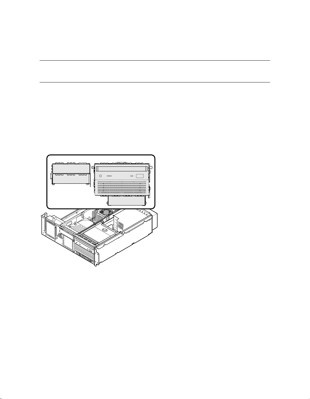
1.9 Storage Cage Options
The AlphaServer TS15 system comes with either an internal storage cage or a front
access storage cage.
1.9.1 Internal Storage Cage
An internal storage cage includes a half-height DVD/CD-RW drive and a half-height bay for
a disk, DVD/CD-RW, or tape drive. The cage supports three 3.5-inch x 1-inch hard disk
drives or two internal 3.5 inch x 1-inch hard disk drives and one 5.25-inch x 1.6-inch
removable media device.
Figure 1–11 Internal Storage Cage Configuration
2
1
1
2
3
3
4
4
Center internal storage bay
X
DVD/CD-RW drive
Y
DVD/CD-RW or internal storage (disk or tape)
Z
Bottom drive
[
MR0591B
System Overview 1-15
Page 32
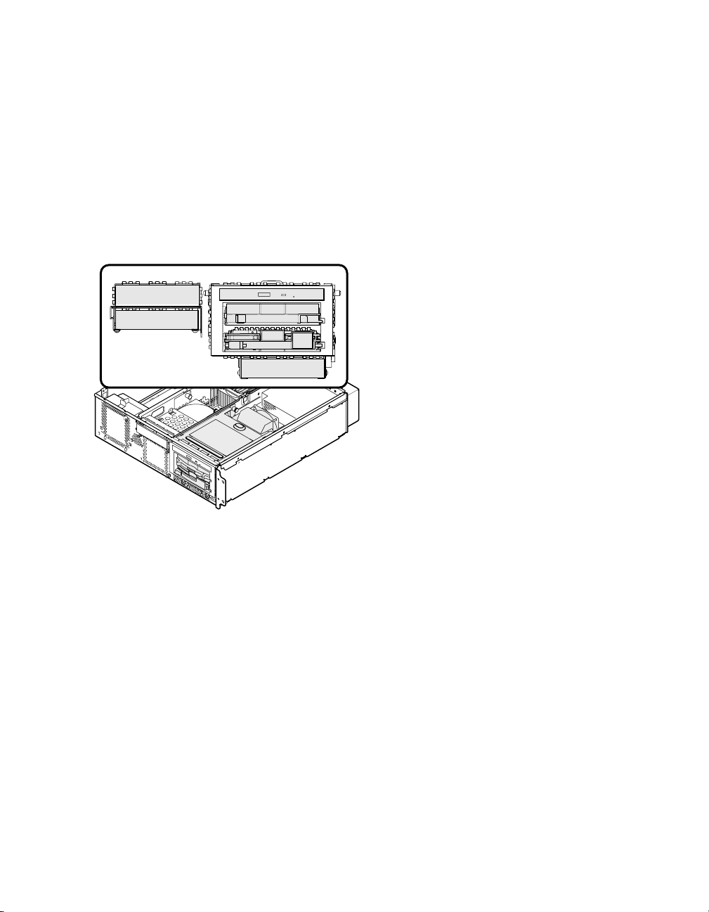
1.9.2 Front Access Storage Cage
A front access storage cage includes a slim-line DVD/CD-RW drive and two 3.5-inch x 1inch hard disk drive bays or one front access universal tape drive bay. The cage supports
two front access 3.5-inch x 1-inch hard disk drives and two internal 3.5-inch x 1-inch hard
disk drives or one front access universal tape drive (AIT or DAT) and two internal disk
drives.
Figure 1–12 Front Access Storage Cage Configuration
2
2
3
1
1
3
4
4
5
5
MR0590B
Center internal storage bay
X
DVD/CD-RW drive
Y
Universal drive
Z
Universal drive
[
Bottom drive
\
1-16 hp AlphaServer TS15 Owner’s Guide
Page 33
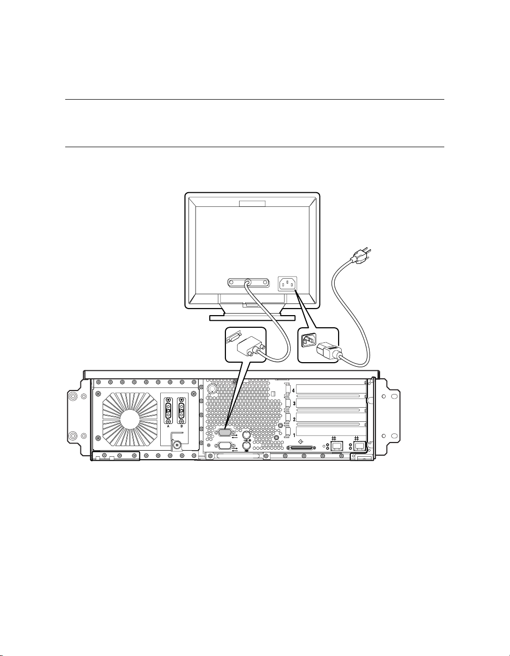
1.10 Console Terminal
The console terminal can be a serial (character cell) terminal connected to the COM1
port or a VGA monitor connected to a video card (VGA adapter). The following
figures identify the proper connections.
Figure 1–13 Console Terminal Connected to COM1 Port
1
2
B
A
MR0646
System Overview 1-17
Page 34
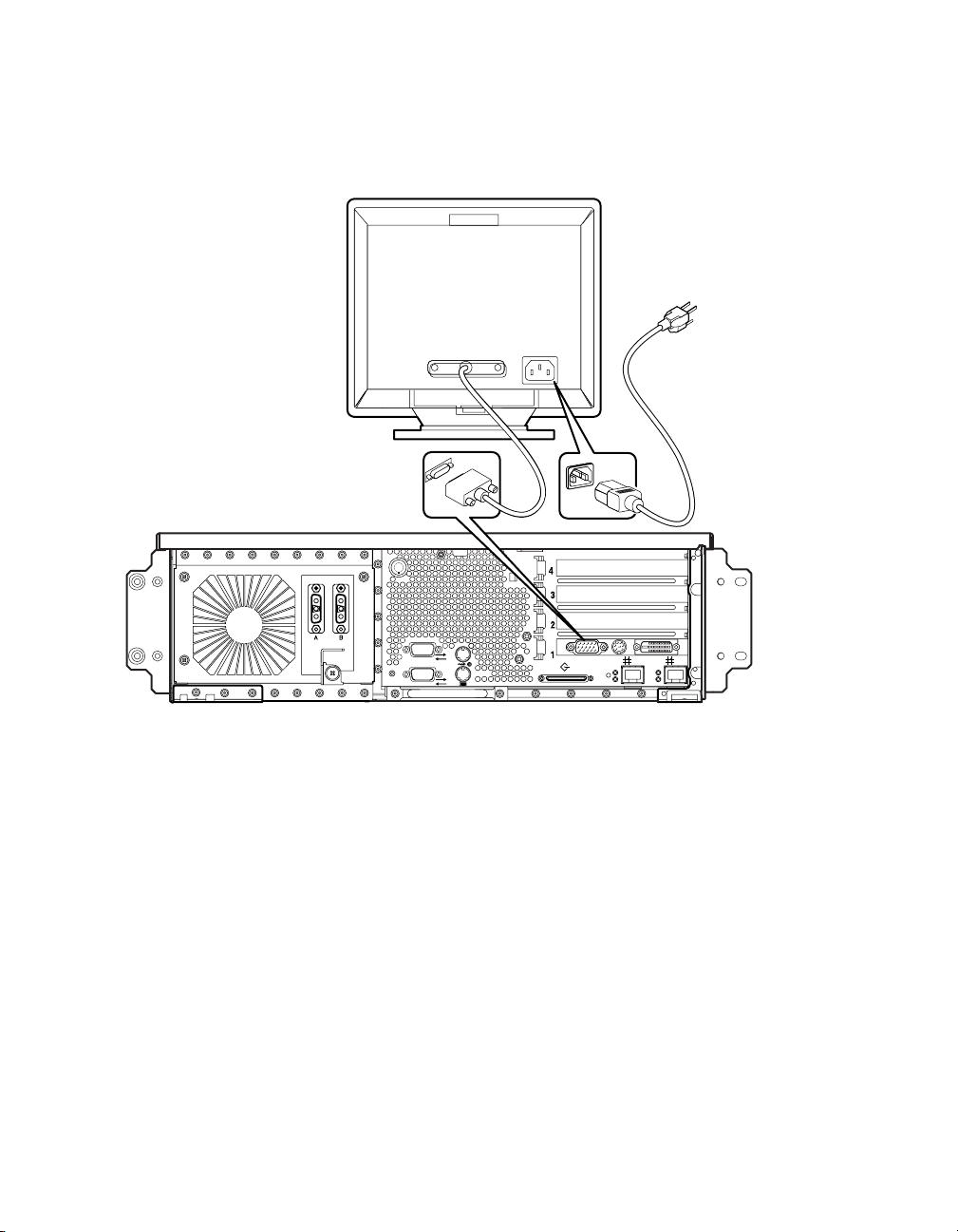
Figure 1–14 VGA Monitor Connected to Optional Video Card
1
2
1-18 hp AlphaServer TS15 Owner’s Guide
B
A
MR0647
Page 35
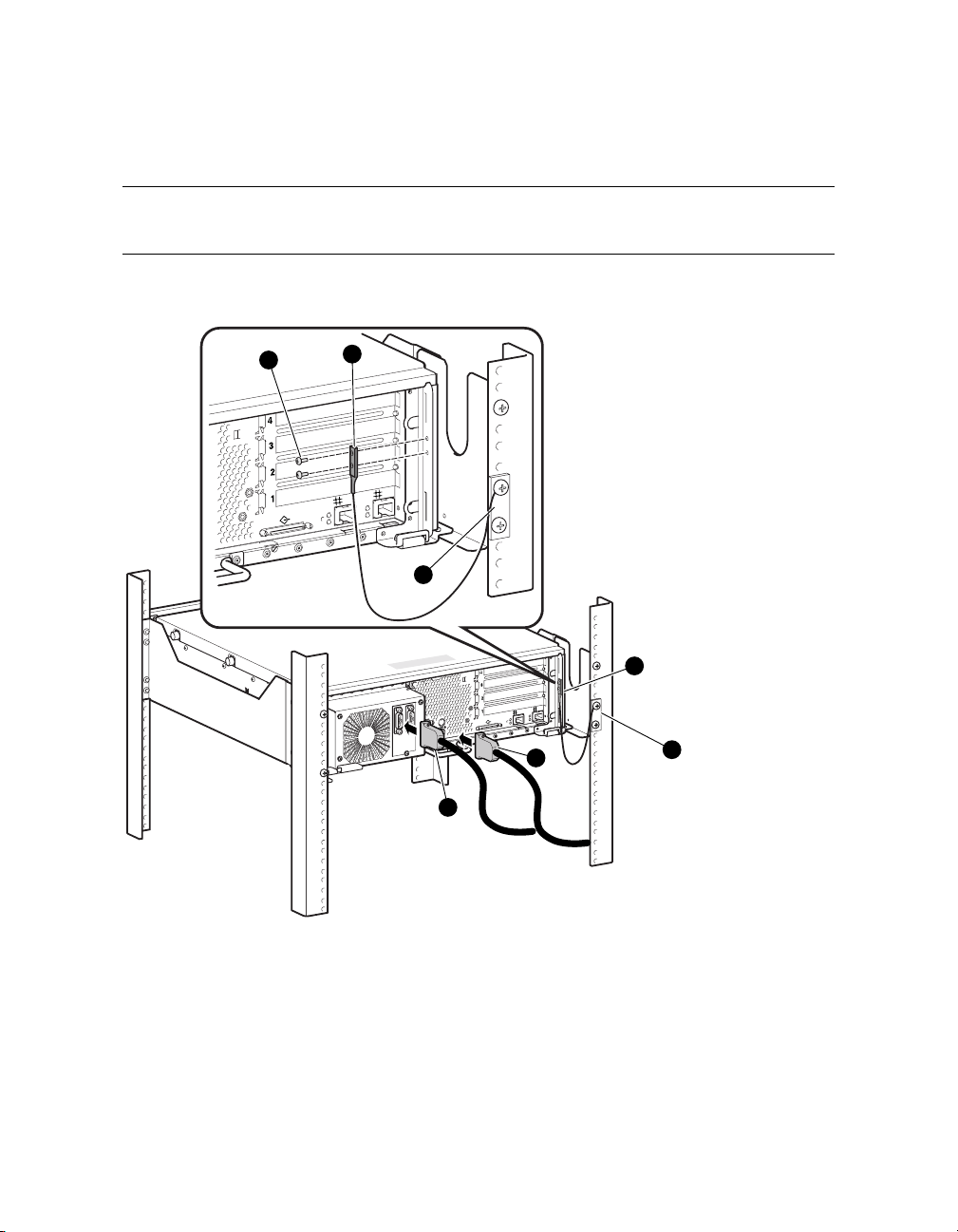
1.11 Ground and Power Connections
The power supply is designed for dual redundant inputs and both power cables must
be installed. A ground cable connects the enclosure to the rack’s vertical rail.
Figure 1–15 Ground and Power Connections
2
1
A
B
3
1
A
1
B
A
2
B
5
3
4
MR0568
System Overview 1-19
Page 36

Cable Connections
One end of the ground cable
10-32 x 0.375-inch screws
p
fastens to the rack with a two 10-32 x 0.625-inch screws.
The power cables
with captive screws.
q r
n
fastens to the inside rear edge of the enclosure with two
o
. See the preceding figure. The other end of the ground cable
plug into the power supply at the rear of the enclosure and fasten
1.12 System Access Lock
The system enclosure has a key lock at the rear. Due to the configuration of the
enclosure, this lock is not functional and can be ignored.
1-20 hp AlphaServer TS15 Owner’s Guide
Page 37

Chapter 2
Operating the System
This chapter provides instructions for basic system operation. The following topics are
covered:
• Powering up the system
• Power-up displays
• SRM console
• Displaying the hardware configuration
• Setting SRM environment variables
• Setting console security
• Updating firmware
Operating the System 2-1
Page 38
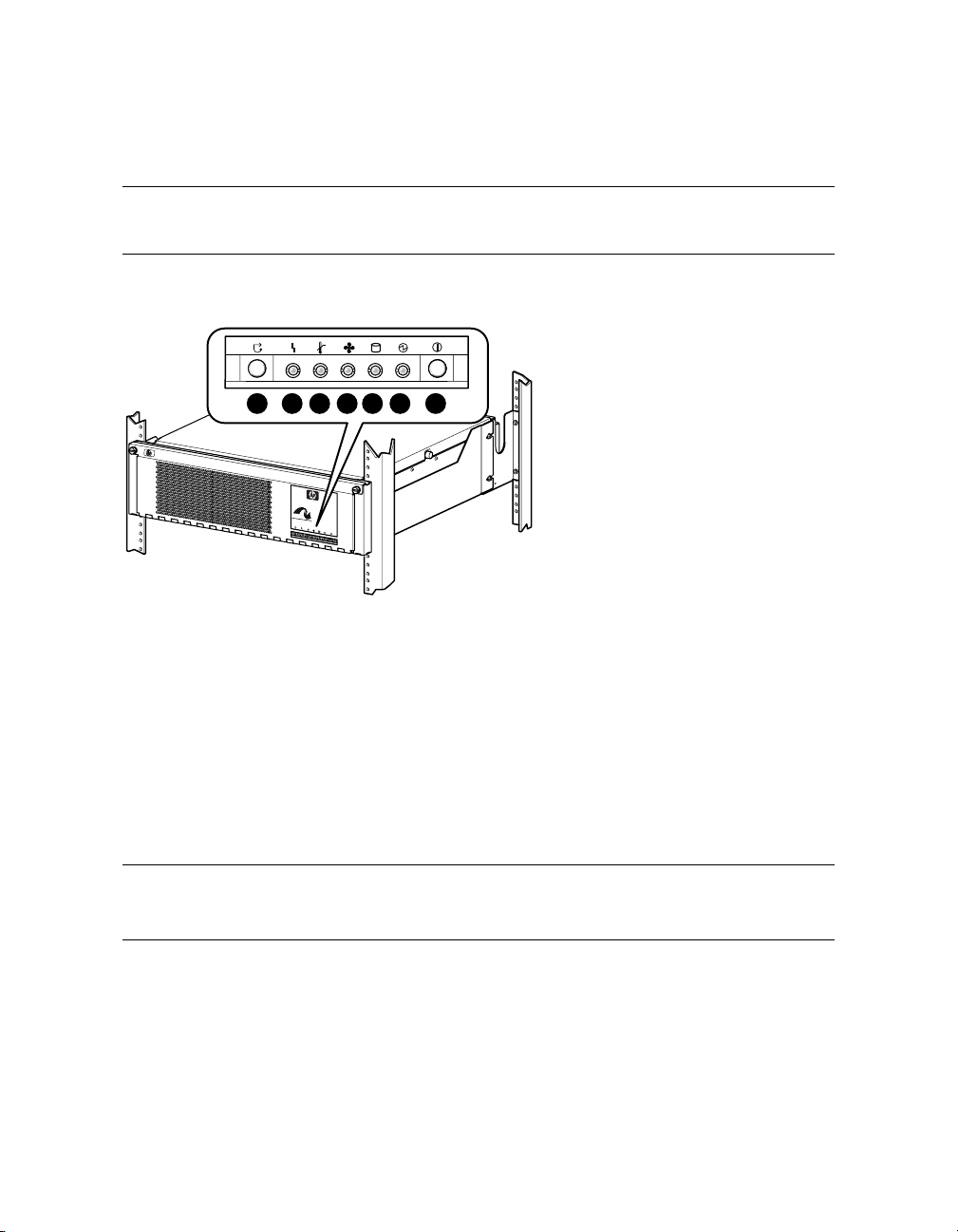
2.1 Powering Up the System
To power up the system, press the power button. Testing begins, and system status
shows on the console terminal screen and at the operator control panel (OCP) display.
Figure 2–1 LEDs on the Operator Control Panel
1
0
A
.
1
0
-
0
6
6
0
5
-
6
3
n
a
r
r
u
c
o
e
u
q
r
a
t
i
v
e
a
r
a
p
o
t
.
n
e
e
i
u
q
m
i
i
r
.
t
n
s
c
e
t
u
e
l
n
a
r
a
t
e
n
m
h
e
l
r
d
i
e
a
c
b
d
c
a
e
a
k
d
t
z
t
u
s
e
o
e
t
t
N
r
n
e
e
a
l
t
l
i
a
n
v
e
g
'
—
i
n
d
c
u
t
n
a
.
i
r
t
f
n
a
n
a
e
—
W
n
i
m
c
r
e
i
i
l
t
a
e
t
a
e
d
n
r
e
t
r
e
d
n
o
m
v
e
i
s
l
e
n
e
a
l
e
u
b
a
§
q
.
l
a
š
a
d
c
t
n
r
h
s
s
o
a
c
c
o
z
m
t
l
a
o
n
s
r
s
h
t
a
o
o
v
–
y
S
d
a
a
g
o
n
r
t
d
n
o
e
o
e
v
n
i
t
t
e
c
g
a
t
e
n
n
n
n
u
a
e
o
d
i
d
c
i
m
e
s
i
l
o
e
m
v
a
'
r
D
a
d
e
o
:
V
s
t
e
r
N
l
î
g
u
I
b
n
z
i
C
a
c
c
i
e
U
i
v
s
r
A
S
e
e
l
C
n
s
E
s
e
e
u
h
R
r
o
e
o
i
P
t
f
Z
e
z
b
e
:
t
s
c
G
e
e
l
N
n
b
U
n
a
T
o
c
c
H
r
s
e
C
D
w
A
o
:
p
N
l
l
O
a
I
t
T
c
N
e
n
E
n
T
o
T
c
A
s
i
D
:
N
O
I
T
U
A
C
MR0621
X
Y
Z
[
\
]
^
1 2 3 4 5 6 7
hp AlphaServer TS15
Certified
Excellence
C
T
e
M
r
t
i
f
i
e
d
E
x
c
e
l
l
e
n
c
e
(
a
n
d
a
D
c
e
e
s
r
i
t
g
i
f
n
i
c
)
a
i
s
t
i
o
n
m
a
r
k
o
f
T
e
l
C
c
o
e
r
r
d
t
i
i
f
a
i
c
.
a
t
i
o
n
N
o
:
0
3
0
0
0
5
N
E
B
S
L
e
v
e
l
3
Halt/Reset button
Amber system fault LED
Amber over temperature fault LED
Amber fan fault LED
Green disk activity LED
Green system power LED
System Power Switch (On/Off)
NOTE: The power button must be in the On position for the RMC power commands
to function.
To control power to the system remotely, use the RMC power off and power on commands.
RMC> power off
RMC> power on
2-2 hp AlphaServer TS15 Owner's Guide
Page 39

2.2 Power-Up Displays
Power-up information is displayed on the operator control panel LEDs and on the
console terminal startup screen. Messages sent from the serial read-only memory
(SROM) program are displayed first, followed by messages from the SRM console.
NOTE: The power-up text that is displayed on the screen depends on the kind of terminal
that is connected as the console terminal: either VT or VGA.
If the SRM console environment variable is set to serial, the entire power-up
display, consisting of the SROM and SRM power-up messages, is displayed on the
VT terminal screen. If console is set to graphics, SROM messages are not
displayed, and the SRM messages are delayed until VGA initialization has
completed. If the COM1_mode is set to through or snoop, RMC will also display
power-up and power-down error messages to COM1.
Operating the System 2-3
Page 40

2.2.1 SROM Power-Up Display
The following example shows sample SROM power-on output. The displayed messages
indicate the status of the various power-on tests performed by the SROM.
Example 2–1 Sample SROM Power-Up Display
SROM V1.3-F CPU # 00 @ 1000 MHz
SROM program starting
Reloading SROM
SROM V1.3-F CPU # 00 @ 1000 MHz
System Bus Speed @ 0125 MHz
SROM program starting
Bcache data tests in progress
Bcache address test in progress
CPU parity and ECC detection in progress
Bcache ECC data tests in progress
Bcache TAG lines tests in progress
Memory sizing in progress
Memory configuration in progress
Testing AAR0
Memory data test in progress
Memory address test in progress
Memory pattern test in progress
Memory initialization
Loading console
Code execution complete (transfer control)
2-4 hp AlphaServer TS15 Owner's Guide
Page 41

2.2.2 SRM Console Power-Up Display
At the completion of SROM power-up, the CPU transfers control to the SRM console,
described in Section 2.3. The SRM console (a command-line interface) continues the
system initialization. Failures are reported to the console terminal through the powerup screen and a console event log.
The explanation for the following example appears after the example.
Example 2–2 SRM Power-Up Display
OpenVMS PALcode V1.96-40, Tru64 UNIX PALcode V1.90-31
starting console on CPU 0
initialized idle PCB
initializing semaphores
initializing heap
initial heap 240c0
memory low limit = 218000 heap = 240c0, 17fc0
initializing driver structures
initializing idle process PID
initializing file system
initializing timer data structures
lowering IPL
CPU 0 speed is 1000 MHz
create dead_eater
create poll
create timer
create powerup
access NVRAM
1536 MB of System Memory
Testing Memory
...
probe I/O subsystem
entering idle loop
starting drivers
create powerup
initializing GCT/FRU at 23e000
Initializing ega dqa dqb eia pka pkb
(Continued)
Operating the System 2-5
Page 42

Memory Testing and Configuration Status
Array Size Base Address Intlv Mode
--------- ---------- ---------------- --------- 0 512Mb 0000000040000000 1-Way
2 1024Mb 0000000000000000 1-Way
1536 MB of System Memory
Testing the System
Testing the Disks (read only)
Testing the Network
AlphaServer TS15 Console V6.3-1, built on Jun 10 2003 at
11:51:30
>>>
Explanation
The CPU prints a message indicating that it is running the console. Starting with this
message, the power-up display is sent to any console terminal, regardless of the state
of the console environment variable.
If console is set to graphics, the display from this point on is saved in a memory
buffer and displayed on the VGA monitor after the PCI buses are sized and the VGA
device is initialized.
The memory size is determined and memory is tested. Memory testing is based on
the “memory_test” environment variable – none, partial, full.
The I/O subsystem is probed and I/O devices are reported. I/O adapters are
configured.
Device drivers are started.
Various diagnostics are performed. Diagnostic testing is based on the
“full_powerup_diags” environment variable – On/Off
The console terminal displays the SRM console banner and the prompt, >>>.
2-6 hp AlphaServer TS15 Owner's Guide
Page 43

2.3 SRM Console
The SRM console is the command-line interface that allows you to set up and boot the
operating system, display the system configuration, set environment variables, and
perform basic system troubleshooting. SRM firmware is located in a flash ROM
(read-only memory) on the system board. The SRM console firmware is described in
detail in Chapter 5, Firmware.
The following sections cover functions you can perform from the SRM console.
Example 2–3 SRM Console Example
>>> set bootdef_dev dkb0,dka0
In this example, the operator enters the SRM set command and specifies the devices from
which to boot the operating system. At power-up the system will try to boot from SCSI
device dkb0 and if unsuccessful, will boot from dka0.
Operating the System 2-7
Page 44

2.3.1 Selecting the Display Device
The SRM console environment variable determines to which display device (VT-type
terminal or VGA monitor) the console display is sent.
The console terminal that displays the SRM user interface can be either a serial terminal
(VT320 or higher, or equivalent) or a VGA monitor.
The SRM console environment variable determines the display device.
• If you use a VT-type device as the console terminal, set the console environment
variable to serial. The VT device must be connected to the Com1 port.
• If you use a VGA monitor as the console terminal, set the console environment variable
to graphics.
You can verify the display device with the SRM show console command and change the
display device with the SRM set console command. If you change the display device
setting, you must reset the system (with the Reset button, if configured to reset, RMC reset
command, SRM init command) to put the new setting into effect.
In the following example, the operator displays the current console device (a graphics
device) and then resets it to a serial device. After the system initializes, output will be
displayed on the serial terminal.
>>> show console
console graphics
>>> set console serial
>>> init
.
2-8 hp AlphaServer TS15 Owner's Guide
Page 45

2.4 Displaying the Hardware Configuration
View the system hardware configuration from the SRM console. It is useful to view
the hardware configuration to ensure that the system recognizes all devices, memory
configuration, and network connections.
Use the following SRM console commands to view the system configuration:
show boot*
show config
show device
show fru
show memory
indicates wildcard notation
*
Displays the boot environment variables.
Displays the logical configuration of interconnects and buses on the
system and the devices found on them.
Displays the bootable devices and controllers in the system.
Displays the physical configuration of FRUs (field-replaceable units).
See Chapter 5 for information on this command.
Displays configuration of main memory.
Operating the System 2-9
Page 46

2.4.1 Displaying Boot Environment Variables
Use the show boot* command to list the boot environment variables. Use the set
command with a variable to set up the boot environment. See Chapter 3 for more
information on setting boot environment variables. You can also use individual
commands like show boot_dev or show boot_reset.
Example 2–4 Show Boot*
>>> show boot*
boot_dev dka0.0.0.1.1
boot_file
boot_osflags a
boot_reset OFF
bootdef_dev dka0.0.0.1.1
booted_dev
booted_file
booted_osflags
Variable Description
boot_dev
Device or device list from which booting is to be attempted, here
SCSI device dka0. (read only)
boot_file
The default file name used for the primary bootstrap when no file
name is specified by the boot command.
boot_osflags
boot_reset
Boot flags, here the Tru64 UNIX “a” (autoboot) flag.
Action taken in response to an error halt or to a boot command.
OFF (the default) indicates a warm boot (no full reset is performed).
bootdef_dev
Device or device list from which booting is to be attempted when
no path is specified on the command line. Here, SCSI device dka0.
booted_dev
booted_file
The device from which booting occurred. (read only)
The file name used for the primary bootstrap during the last boot.
(read only)
booted_osflags
(read only)
Additional parameters, if any, specified by the -flags option of the
last boot command. For example, if boot -flags s dka0 was the last
boot command, then ‘s’ is stored in the booted_osflags variable.
2-10 hp AlphaServer TS15 Owner's Guide
Page 47

2.4.2 Displaying the Logical Hardware Configuration
Use the show config command to display the logical configuration. To display the
physical configuration, issue the show fru command.
The explanation for the following example appears after the example.
Example 2–5 Show Config
>>>show config
hp AlphaServer TS15
Firmware
SRM Console: X6.6-24
PALcode: OpenVMS PALcode V1.98-6, Tru64 UNIX PALcode V1.92-7
SROM Extended: V1.0-1
SROM Fail Safe: V1.0-0
RMC Runtime: V1.1-0
RMC Booter: V1.1-0
Processors
CPU 0 Alpha EV68CB pass 4.0 1000 MHz 2MB Bcache
Core Logic
Cchip Rev 18
Dchip Rev 17
PPchip 0 Rev 17
TIG Rev 1.11
Acer Chip Revision A1-E
Memory
Array Size Base Address Intlv Mode
--------- ---------- ---------------- --------- 0 1024Mb 0000000000000000 2-Way
2 1024Mb 0000000040000000 2-Way
2048 MB of System Memory
Slot Option Hose 0, Bus 0, PCI - 33 MHz
7 Acer Labs M1543C Bridge to Bus 1, ISA
8/0 Adaptec AIC-7899 pka0.7.0.8.0 SCSI Bus ID 7
dka0.0.0.8.0 COMPAQ BF03665A32
dka100.1.0.8.0 COMPAQ BF03665A32
8/1 Adaptec AIC-7899 pkb0.7.0.108.0 SCSI Bus ID 7
9 Intel 82559ER Ethern eia0.0.0.9.0 00-02-A5-20-C0-39
(Continued)
Operating the System 2-11
Page 48

10 Intel 82559ER Ethern eib0.0.0.10.0 00-02-A5-20-C0-3A
13 Acer Labs M1543C IDE dqa.0.0.13.0
dqb.0.1.13.0
dqa0.0.0.13.0 DW-224E
Slot Option Hose 0, Bus 1, ISA
Floppy dva0.0.0.1000.0
Slot Option Hose 2, Bus 0, PCI - 66 MHz
7 Radeon 7500 PCI vga0.0.0.7.2
SROM loads from Flash
Console loads from SRM
Flash updates are Enabled for RMC
Flash updates are Enabled for SRM
Flash updates are Enabled for FailSafe
Flash updates are Disabled for RMC Booter
Halt/Reset is set to HALT
>>>
Explanation
Firmware. Version numbers of the SRM console, PALcode, serial ROM, and RMC
Processors. Processors present, processor version and clock speed, and amount of
backup cache
Core logic. Version numbers of chips that form the interconnect on the motherboard
Memory. Memory arrays and memory size
This part of the command output shows the PCI buses.
The “Slot” column lists the slots (logical IDs) seen by the system. Logical IDs
identify both installed PCI cards and onboard chips. The logical IDs do not
correspond directly to the physical slots into which the devices are installed. See
Table 2–1 for the correspondence between logical IDs and physical slots.
The slots in the preceding example have the following meanings.
NOTE: The naming of devices (for example, dqa0.0.0.13.0) follows the conventions
given in Table 2–2.
Hose 0, Bus 0, PCI
Slot 7 Onboard Acer chip. Provides bridge to ISA Bus 1
Slot 8 Slots 8/0, 8/1 Onboard Dual Channel Adaptec controller
Slot 9 Onboard 10/100 Mb Ethernet (Port A)
Slot 10 Onboard 10/100 Mb Ethernet (Port B)
Slot 13 Onboard Acer chip IDE
2-12 hp AlphaServer TS15 Owner's Guide
Page 49

Hose 0, Bus 1
The Acer is configured to use a floppy, but the device is not present.
Hose 2, Bus 0, PCI
Slots 7 and 8 are 66MHz/33MHz and slots 9 and 10 are 33 MHz.
Slot 7 is an ATI Radeon 7500 Graphics Accelerator running at 66 MHz.
Jumpers. State of jumper settings
Table 2–1 How Physical I/O Slots Map to Logical Slots
Physical Slot SRM Logical Slot ID
1
2
3
4
Hose 2 Slot ID 7
Hose 2 Slot ID 8
Hose 2 Slot ID 9
Hose 2 Slot ID 10
2.4.3 Displaying the Bootable Devices
Use the show device command to display the devices from which the operating system
can be booted.
Example 2–6 Show Device
>>>show device
dka0.0.0.8.0 DKA0 COMPAQ BF03665A32 3B01
dka100.1.0.8.0 DKA100 COMPAQ BF03665A32 3B01
dqa0.0.0.13.0 DQA0 DW-224E A.1J
dva0.0.0.1000.0 DVA0
eia0.0.0.9.0 EIA0 00-02-A5-20-C0-39
eib0.0.0.10.0 EIB0 00-02-A5-20-C0-3A
pka0.7.0.8.0 PKA0 SCSI Bus ID 7
pkb0.7.0.108.0 PKB0 SCSI Bus ID 7
>>>
The third device in the printout,
table.
dqa0.0.0.13.0
, is used as an example in the following
Operating the System 2-13
Page 50

Table 2–2 Device Naming Conventions
Category Description
Driver ID Two-letter designator of port or class driver
dq
dk SCSI drive or CD ew Ethernet port
dq IDE CD-ROM fw FDDI device
dr RAID set device mk SCSI tape
du DSSI disk mu DSSI tape
eg Ethernet port pu DSSI port
ei Ethernet port pz KZPCC-CE RAID
controller
a
Storage adapter ID One-letter designator of storage adapter (a, b, c…).
0
Device unit number Unique number (MSCP unit number). SCSI unit numbers are
forced to 100 X node ID.
0
Bus node number Bus node ID.
0
Channel number Used for multi-channel devices.
13
Logical slot number IDE that is onboard.
0
Hose number
• 0 PCI 0
• 2 PCI 2
2-14 hp AlphaServer TS15 Owner's Guide
Page 51

2.4.4 Viewing the Memory Configuration
Use the show memory command to view the configuration of main memory.
Example 2–7 Show Memory
>>> show memory
Array Size Base Address Intlv Mode
--------- ---------- ---------------- --------- 0 1024Mb 0000000000000000 1-Way
1024 MB of System Memory
>>>
Explanation
The show memory display corresponds to the memory array configuration described in
Chapter 4. The display does not indicate the number of DIMMs or the DIMM size.
The output of the show memory command also provides the memory interleaving status of
the system.
Use the show fru command to display the DIMMs in the system and their location. See
Chapter 5.
Operating the System 2-15
Page 52

2.5 Setting SRM Environment Variables
You may need to set several SRM console environment variables and built-in utilities
to configure the system.
You can set environment variables at the >>> prompt.
• To check the setting for a specific environment variable, enter the show envar
command, where the name of the environment variable is substituted for envar. To see
a list of the environment variables, enter the show * command. For example, to display
the default boot device, use show bootdef_dev.
• To reset an environment variable, use the set envar command, where the name of the
environment variable is substituted for envar. For example, to set the default boot
dkb0
device to
• To turn off console security for the current console session, use the login command.
The environment variables used to set up the boot environment are described in Chapter 3.
Chapter 5 covers other environment variables you are likely to use.
, use set bootdef_dev dkb0.
2-16 hp AlphaServer TS15 Owner's Guide
Page 53

2.6 Setting Console Security
You can set the SRM console to secure mode to prevent unauthorized persons from
modifying the system parameters or otherwise tampering with the system from the
console.
When the SRM is set to secure mode, you can use only three console commands:
• The boot command, to boot the operating system.
• The continue command, to resume running the operating system if you have
inadvertently halted the system.
The boot command cannot take command-line parameters when the console is in secure
mode. The console boots the operating system using the environment variables stored in
NVRAM (boot_file, bootdef_dev, boot_osflags).
The console security commands are as follows:
set password
set secure
clear password
login
NOTE: The security features work only if access to the system hardware is denied to
unauthorized persons. Be sure the system is available only to authorized persons.
These commands put the console into secure mode.
Exits secure mode.
Turns off console security for the current session. Once you enter the
login command in secure mode, you can enter any SRM command as
usual. However, the system automatically returns to secure mode
when you enter the boot or continue command or when you reset the
system.
Operating the System 2-17
Page 54

2.6.1 Setting the Console Password
Set the console password with the set password command. A password is required for
operating the system in secure mode.
Example 2–8 Set Password
>>> set password
Please enter the password:
Please enter the password again:
>>>
>>> set password
Please enter the password:
Please enter the password again:
Now enter the old password:
>>>
>>> set password
Please enter the password:
Password length must be between 15 and 30 characters
>>>
Explanation
The set password command sets the console password for the first time or changes an
existing password. It is necessary to set the password only if the system is going to operate
in secure mode.
The syntax is: set password
Setting a password. If a password has not been set and the set password command is
issued, the console prompts for a password and verification. The password and
verification are not echoed.
Changing a password. If a password has been set and the set password command is
issued, the console prompts for the new password and verification, then prompts for
the old password. The password is not changed if the validation password entered
does not match the existing password stored in nonvolatile RAM (NVRAM).
The password length must be between 15 and 30 alphanumeric characters. Any
characters entered after the 30th character are not stored.
2-18 hp AlphaServer TS15 Owner's Guide
Page 55

2.6.2 Setting the Console to Secure Mode
To set the console to secure mode, first set the password. Then enter the set secure
command. The system immediately enters secure mode.
Example 2–9 Set Secure
>>> set secure
Console is secure. Please login.
>>> b dkb0
Console is secure - parameters are not allowed.
>>> login
Please enter the password:
>>> b dkb0
(boot dkb0.0.0.3.1)
.
.
.
Explanation
The set secure command enables secure mode. If no password has been set, you are
prompted to set the password. Once you set a password and enter the set secure command,
secure mode is in effect immediately and only the continue, boot (using the stored
parameters), and login commands can be performed.
The syntax is: set secure
The console is put into secure mode, and then the operator attempts to boot the
operating system with command-line parameters. A message is displayed indicating
that boot parameters are not allowed when the system is in secure mode.
The login command is entered to turn off security features for the current console
session. After successfully logging in, the operator enters a boot command with
command-line parameters.
Operating the System 2-19
Page 56

2.6.3 Turning Off Security During a Console Session
The login command turns off the security features, enabling access to all SRM console
commands during the current console session. The system automatically returns to
secure mode as soon as the boot or continue command is entered or when the system is
reset.
Example 2–10 Login
>>> login
Secure not set. Please set the password.
>>> set password
Please enter the password:
Please enter the password again:
>>> login
Please enter the password:
>>> show boot*
Explanation
The login command is entered, but the system is not in secure mode. A password
must be set.
A password is set.
The login command is entered. After the password is entered, console security is
turned off for the current session and the operator can enter commands such as show
boot*.
2-20 hp AlphaServer TS15 Owner's Guide
Page 57

When you enter the login command, you are prompted for the current system password. If a
password has not been set, a message is displayed indicating that there is no password in
NVRAM. If a password has been set, this prompt is displayed:
Please enter the password:
If the password entered matches the password in NVRAM, when the prompt is redisplayed
the console is no longer in secure mode and all console commands can be performed during
the current console session.
If You Forget the Password
If you forget the current password, use the login command in conjunction with an RMC halt
in/out to clear the password, as follows:
1.
Enter the login command:
>>> login
2. When prompted for the password, enter the RMC and issue the halt in command, press
the Return (Enter) key.
3. At the SRM prompt (>>>), enter the clear password command, then enter the RMC
and issue the halt out command.
The password is now cleared and the console cannot be put into secure mode unless you set
a new password.
Operating the System 2-21
Page 58

2.6.4 Returning to User Mode
The clear password command clears the password environment variable, setting it to
zero. Once the password is cleared, you are returned to user mode.
Example 2–11 Clear Password
>>> clear password
Please enter the password:
Console is secure
>>> clear password
Please enter the password:
Password successfully cleared.
>>>
Explanation
The wrong password is entered. The system remains in secure mode.
The password is successfully cleared.
The clear password command is used to exit secure mode and return to user mode. To use
clear password, you must know the current password. Once you clear the password, the
console is no longer secure.
To clear the password without knowing the current password, you must use the login
command in conjunction with the RMC halt command, as described in Section 2.6.3.
2-22 hp AlphaServer TS15 Owner's Guide
Page 59

2.7 Updating Firmware
Typically, you update system firmware whenever the operating system is updated.
You might also need to update firmware if you add I/O device controllers and
adapters, if enhancements are made to the firmware, or if the serial ROM or RMC
firmware become corrupted.
Sources of Firmware Updates
The system firmware resides in the flash ROM located on the system board. The Alpha
Systems Firmware Update Kit comes on a CD-ROM, which is updated quarterly. You can
also obtain Alpha firmware updates from the Internet.
Quarterly Update Service
The Alpha Systems Firmware Update Kit CD-ROM is available by subscription from HP.
Alpha Firmware Internet Access
You can also obtain Alpha firmware update files from the Internet:
http://ftp.digital.com/pub/DEC/Alpha/firmware/
2.7.1 Using the Loadable Firmware Update Utility
The system firmware is updated from a Loadable Firmware Update Utility (LFU).
When you boot the medium containing the update image, the LFU banner and
command descriptions are displayed. Enter commands at the UPD> prompt.
Before updating the firmware, enter the list command to list the current revision of the
firmware. Enter the update command to update the firmware automatically. See the
following example.
Example 2–12 Updating the Firmware
Checking dqa0.0.0.16.0 for the option firmware files. . .
Checking dva0.0.0.1000.0 for the option firmware files. . .
Option firmware files were not found on CD or floppy.
If you want to load the options firmware,
please enter the device on which the files are located(ewa0),
or just hit <return> to proceed with a standard console update:
Operating the System 2-23
Page 60

***** Loadable Firmware Update Utility *****
------------------------------------------------------------- Function Description
------------------------------------------------------------- Display Displays the system's configuration table.
Exit Done exit LFU (reset).
List Lists the device, revision, firmware name, and update
Update Replaces current firmware with loadable data image.
Verify Compares loadable and hardware images.
? or Help Scrolls this function table.
--------------------------------------------------------------
UPD> list
Device Current Revision Filename Update Revision
SRM V6.3-1 srm_fw V6.3-1
srom V1.3-F srom_fw V1.3-F
rt V0.5-6 rt_fw V0.5-9 (rt = RMC Runtime)
cipca_fw A420
dfxaa_fw 3.20
fca_2354_fw CS3.81A4
kgpsa_8k_fw DS3.81A4
kzpcc_smor 1.12
kzpcc_fw CQ16
kzpsa_fw A12
UPD> update srm
Confirm update on:
srm
[Y/(N)] y
WARNING: updates may take several minutes to complete for each
device.
DO NOT ABORT!
srm Updating to 6.3-1... Verifying 6.3-1... PASSED.
UPD> list
.
.
.
UPD> exit
revision
2-24 hp AlphaServer TS15 Owner's Guide
Page 61

2.7.2 Manually Updating TIG or RMC Booter
If the TIG or RMC booter needs to be updated, you can perform a manual update.
1. Boot the update medium.
2. At the UPD> prompt, enter the exit command and answer y at the prompt:
***** Loadable Firmware Update Utility *****
------------------------------------------------------------------ Function Description
------------------------------------------------------------------ Display Displays the system's configuration table.
Exit Done exit LFU (reset).
List Lists the device, revision, firmware name, and update
revision.
Update Replaces current firmware with loadable data image.
Verify Compares loadable and hardware images.
? or Help Scrolls this function table.
-------------------------------------------------------------------
UPD> exit
Do you want to do a manual update? [y/(n)] y
***** Loadable Firmware Update Utility *****
------------------------------------------------------------------ Function Description
------------------------------------------------------------------ Display Displays the system's configuration table.
Exit Done exit LFU (reset).
List Lists the device, revision, firmware name, and update
revision.
Update Replaces current firmware with loadable data image.
Verify Compares loadable and hardware images.
? or Help Scrolls this function table.
-------------------------------------------------------------------
UPD>
(Continued)
Operating the System 2-25
Page 62

3. To update the TIG enter update tig For example:
UPD> update tig
Confirm update on:
tig [Y/(N)]y
WARNING: updates may take several minutes to complete for each
device.
DO NOT ABORT!
tig Updating to 1.11... Verifying 1.11... PASSED.
UPD>
2.7.3 Updating from the CD-ROM
You can update the system firmware from CD-ROM.
1. At the SRM console prompt, enter the show device command to determine the drive
name of the CD-ROM drive.
2. Load the Alpha Systems Firmware Update CD into the drive.
3. Boot the system from the CD, using the drive name determined in step 1 (for example,
dqa0).
>>> boot dqa0
4. Enter the update command at the UPD> prompt.
5. When the update is complete, exit from the Firmware Update Utility.
UPD> exit
2-26 hp AlphaServer TS15 Owner's Guide
Page 63

2.7.4 Updating from an OpenVMS System Disk
You can update the firmware from an OpenVMS system disk.
1. Download the firmware update image from the Firmware Updates Web site.
2. Rename the downloaded file to fwupdate.exe.
3. Enter the following commands on the OpenVMS Alpha system:
$ set file/attr=(rfm:fix,lrl:512,mrs:512,rat:none) fwupdate.exe
$ copy/contiguous fwupdate.exe "system_disk":[sys0.sysexe]
NOTE: Insert the name of your system disk in place of "system_disk," for example,
dka100.
4. Shut down the operating system to get to the SRM console prompt.
5. Boot the update utility from the SRM console as follows:
>>> boot dka100 -flags 0,a0
NOTE: Replace dka100 with the name of the system disk, if different.
6. After some messages are displayed, you will be prompted for the bootfile. Enter the
directory and file name as follows:
Bootfile: [sys0.sysexe]fwupdate.exe
7. Enter the update command at the UPD> prompt.
Operating the System 2-27
Page 64

2.7.5 Updating from the Network
You can update firmware from the network using the MOP protocol for OpenVMS or
the BOOTP protocol for Tru64 UNIX.
Updating Firmware Using BOOTP
1. Download the firmware update image from the Firmware Updates Web site.
2. Copy the downloaded file to a UNIX based network server for BOOTP booting on the
system. For details on configuring the BOOTP server, refer to Tru64 UNIX
documentation or the system's Firmware Release Notes document.
3. Boot the update file. For example:
>>>boot -file <update_file> -prot bootp eia0
4. Enter the update command at the UPD> prompt.
Updating Firmware Using MOP
1. Download the firmware update image from the Firmware Updates Web site.
2. Copy the downloaded file to an OpenVMS based network server for MOP booting on
the system. For details on configuring the MOP server, refer to OpenVMS
documentation or the system's Firmware Release Notes document.
3. To ensure that the downloaded file is in a proper VMS fixed record format, enter the
following command before using the file for MOP booting:
$ set file/attr=(rfm:fix,lrl:512,mrs:512,rat:none) “fwupdate.sys”
NOTE: Replace “fwupdate.sys” with the name of the firmware image you
downloaded.
4. Boot the update file. For example:
>>> boot -file fwupdate eia0 –prot mop
5. Enter the update command at the UPD> prompt.
2-28 hp AlphaServer TS15 Owner's Guide
Page 65

Chapter 3
Booting and Installing an Operating
System
This chapter gives instructions for booting the Tru64 UNIX or OpenVMS operating systems
and for starting an operating system installation. It also describes how to switch from one
operating system to another. Refer to your operating system documentation for complete
instructions on booting or starting an installation.
The following topics are included:
• Setting Boot Options
• Booting Tru64 UNIX
• Starting a Tru64 UNIX Installation
• Booting OpenVMS
• Booting OpenVMS from the InfoServer
• Starting an OpenVMS Installation
NOTE: Your system may have been delivered to you with factory-installed software
(FIS); that is, with a version of the operating system already installed. If so, refer
to the FIS documentation included with your system to boot your operating
system for the first time.
Booting and Installing an Operating System 3-1
Page 66

3.1 Setting Boot Options
You can set a default boot device, boot flags, and network boot protocols for Tru64
UNIX or OpenVMS using the SRM set command with environment variables. Once
these environment variables are set, the boot command defaults to the stored values.
You can override the stored values for the current boot session by entering parameters
on the boot command line.
The SRM boot-related environment variables are listed below and described in the
following sections.
auto_action
bootdef_dev
boot_file
boot_osflags
eg*0_inet_init
ei*0_inet_init
ew*0_inet_init
eg*0_protocols
ei*0_protocols
ew*0_protocols
Determines the default action the system takes when the system is
power cycled, reset, or experiences a failure.
Device or device list from which booting is to be attempted when
no path is specified on the command line.
Specifies a default file name to be used for booting when no file
name is specified by the boot command.
Defines parameters (boot flags) used by the operating system to
determine some aspects of a system bootstrap.
Determines whether the interface's internal Internet database is
initialized from nonvolatile RAM (NVRAM) or from a network
server (through the bootp protocol). Set this environment variable
if you are booting Tru64 UNIX from a Remote Installation
Services (RIS) server.
Defines a default network boot protocol (bootp or mop).
3-2 hp AlphaServer TS15 Owner's Guide
Page 67

3.1.1 auto_action
The auto_action environment variable specifies the action the console takes any time
the system powers up, fails, or resets. The value of auto_action takes effect only after
you reset the system by pressing the Reset button (if configured), issuing the reset
command from the Remote Management Console (RMC), or issuing the init command
from the SRM.
The default setting for auto_action is halt. With this setting, the system stops in the SRM
console after being initialized. To cause the operating system to boot automatically after
initialization, set the auto_action environment variable to boot or restart.
• When auto_action is set to boot, the system boots from the default boot device
specified by the value of the bootdef_dev environment variable.
• When auto_action is set to restart, the system boots from whatever device it booted
from before the shutdown/reset or failure.
NOTE: After you set the auto_action environment variable, it is recommended that you
set the boot device and operating system flags as well, using the set bootdef_dev
and set boot_osflags commands.
The syntax is:
set auto_action value
The options for value are:
halt
boot
restart
The system remains in console mode after power-up or a system crash.
The operating system boots automatically after either the SRM init command
is issued, the Reset button is pressed (if configured), or the reset command is
issued from the RMC.
Restarts the operating system and tries to begin where it left off. If that fails,
then it will reboot the operating system.
The operating system boots automatically after either the SRM init command
is issued, the Reset button is pressed (if configured), or the reset command is
issued from the RMC. It also reboots after an operating system crash.
Booting and Installing an Operating System 3-3
Page 68

Examples
In the following example, the operator sets the auto_action environment variable to restart.
The device specified with the bootdef_dev environment variable is dka0. When Tru64
UNIX is shut down and rebooted, the system will reboot from dka0.
>>> show auto_action
auto_action halt
>>> set auto_action restart
>>> init
.
.
.
>>> show auto_action
auto_action restart
>>> show bootdef_dev
bootdef_dev dka0
>>> boot
...
[Login to UNIX and shutdown/reboot]
#shutdown -r now
...
console will boot from dka0
In the following example, auto_action is set to restart, but Tru64 UNIX is booted from a
device other than the device set with bootdef_dev. When Tru64 UNIX is shut down and
rebooted, the system reboots from the specified device.
>>> boot dka100
.
.
.
[Log in to UNIX and shutdown/reboot]
#shutdown -r now
...
console will boot from dka100
3-4 hp AlphaServer TS15 Owner's Guide
Page 69

3.1.2 bootdef_dev
The bootdef_dev environment variable specifies one or more devices from which to
boot the operating system. When more than one device is specified, the system searches
in the order listed, and boots from the first device with operating system software.
Enter the show bootdef_dev command to display the current default boot device. Enter the
show device command for a list of all devices in the system.
The syntax is:
set bootdef_dev boot_device
boot_device The name of the device on which the system software has been loaded. To
specify more than one device, separate the names with commas.
Example
In this example, two boot devices are specified. The system will try booting from dkb0 and
if unsuccessful, will boot from dka0.
>>> set bootdef_dev dkb0, dka0
NOTE: When you set the bootdef_dev environment variable, it is recommended that you
set the operating system boot parameters as well, using the set boot_osflags
command.
Booting and Installing an Operating System 3-5
Page 70

3.1.3 boot_file
The boot_file environment variable specifies the default file name to be used for
booting when no file name is specified by the boot command. The factory default value
is null.
The syntax is:
set boot_file filename
Example
In this example, the system is set to boot using the file
>>> set boot_file vmunix
vmunix.
3-6 hp AlphaServer TS15 Owner's Guide
Page 71

3.1.4 boot_osflags
D
The boot_osflags environment variable sets the default boot flags and, for OpenVMS, a
root number.
Boot flags contain information used by the operating system to determine some aspects of a
system bootstrap. Under normal circumstances, you can use the default boot flag settings.
To change the boot flags for the current boot only, use the –flags option with the boot
command.
The syntax is:
set boot_osflags flags_value
The flags_value argument is specific to the operating system.
Tru64 UNIX Systems
Tru64 UNIX systems take a single ASCII character as the flags_value argument.
Load operating system software from the specified boot device (autoboot). Boot to
a
multi-user mode.
Prompt for the name of a file to load and other options (boot interactively). Boot to
i
single-user mode.
Stop in single-user mode. Boots /vmunix to single-user mode and stops at the # (root)
s
prompt.
Full dump; implies “s” as well. By default, if Tru64 UNIX crashes, it completes a
partial memory dump. Specifying “D” forces a full dump at system crash.
Example
The following setting will autoboot Tru64 UNIX to multi-user mode when you enter the
boot command.
>>> set boot_osflags a
Booting and Installing an Operating System 3-7
Page 72

OpenVMS Systems
OpenVMS systems require an ordered pair, separated by a comma, as the flags_value
argument: root_number, boot_flags.
root_number Directory number of the system disk on which OpenVMS files are located.
For example:
root_number Root Directory
0 (default) [SYS0.SYSEXE]
1 [SYS1.SYSEXE]
2 [SYS2.SYSEXE]
3 [SYS3.SYSEXE]
boot_flags The hexadecimal value of the bit number or numbers set. To specify
multiple boot flags, add the flag values (logical OR). For example, the flag
value 10080 executes both the 80 and 10000 flag settings. See Table 3–1.
Table 3–1 OpenVMS Boot Flag Settings
Flags_Value Bit Number Meaning
1 0 Bootstrap conversationally (enables you to modify
SYSGEN parameters in SYSBOOT).
2 1 Map XDELTA to a running system.
4 2 Stop at initial system breakpoint.
8 3 Perform diagnostic bootstrap.
10 4 Stop at the bootstrap breakpoints.
20 5 Omit header from secondary bootstrap image.
80 7 Prompt for the name of the secondary bootstrap file.
100 8 Halt before secondary bootstrap.
10000 16 Display debug messages during booting.
20000 17 Display user messages during booting.
3-8 hp AlphaServer TS15 Owner's Guide
Page 73

Examples
In the following OpenVMS example, root_number is set to 2 and boot_flags is set to 1.
With this setting, the system will boot from root directory [SYS2.SYSEXE] to the
SYSBOOT prompt when you enter the boot command.
>>> set boot_osflags 2,1
In the following OpenVMS example, root_number is set to 0 and boot_flags is set to 80.
With this setting, you are prompted for the name of the secondary bootstrap file when you
enter the boot command.
>>> set boot_osflags 0,80
3.1.5 eg*0_inet_init, ei*0_inet_init, ew*0_inet_init
The eg*0_inet_init, ei*0_inet_init, or ew*0_inet_init environment variable determines
whether the interface's internal Internet database is initialized from nvram or from a
network server (through the bootp protocol). Legal values are nvram and bootp. The
default value is bootp. Set this environment variable if you are booting Tru64 UNIX
from a RIS server.
To list the network devices on your system, enter the show device command. The Ethernet
controllers start with the letters “eg”, “ei” or “ew,” for example, ewa0. The third letter is
the adapter ID for the specific Ethernet controller. Replace the asterisk (*) with the adapter
ID letter when using this command.
The syntax is:
set eg*0_inet_init value or
set ei*0_inet_init value or
set ew*0_inet_init value
The value is one of the following:
Nvram
Bootp
Initializes the internal Internet database from nvram.
Initializes the internal Internet database from a network server through the
bootp protocol.
Example
>>> set ewa0_inet_init bootp
Booting and Installing an Operating System 3-9
Page 74

3.1.6 ex*_protocols
The eg*0_protocols, ei*0_protocols, or ew*0_protocols environment variable sets
network protocols for booting and other functions.
To list the network devices on your system, enter the show device command. The Ethernet
controllers start with the letters “eg,” “ei,” or “ew,” for example, ewa0. The third letter is
the adapter ID for the specific Ethernet controller. Replace the asterisk (*) with the adapter
ID letter when entering the command.
The syntax is:
set eg*0_protocols protocol_value or
set ei*0_protocols protocol_value or
set ew*0_protocols protocol_value
The options for protocol_value are:
mop (default) Sets the network protocol to mop (Maintenance Operations Protocol),
the setting typically used with the OpenVMS operating system.
bootp
Sets the network protocol to bootp, the setting typically used with the
Tru64 UNIX operating system.
bootp,mop
When both are listed, the system attempts to use the mop protocol first,
regardless of which is listed first. If not successful, it then attempts the
bootp protocol.
Example
>>> show device
dqa0.0.0.16.0 DQA0 HL-DT-ST GCE-8302B 2.01
dva0.0.1000.0* DVA0
ega0.0.0.5.2 EGA0 00-00-00-00-00-00
eia0.0.0.8.0 EIA0 40-00-04-A5-F8-00
pka0.7.0.1.2 PKA0 SCSI Bus ID 7
pkb0.7.0.101.2 PKB0 SCSI Bus ID 7
>>>
* TS15 systems have no floppy drive.
3-10 hp AlphaServer TS15 Owner's Guide
Page 75

3.2 Booting Tru64 UNIX
Tru64 UNIX can be booted from a CD-ROM on a local drive (a CD-ROM drive
connected to the system), from a local SCSI disk, or from a UNIX RIS server. The
following example shows an abbreviated boot from a local SCSI disk drive. For
complete instructions on booting Tru64 UNIX, see the Tru64 UNIX Installation Guide.
The explanation for the following example appears after the example.
Example 3–1 Booting Tru64 UNIX from a Local SCSI Disk
>>>boot dka0
(boot dka0.0.0.8.0 -file vmunix)
block 0 of dka0.0.0.8.0 is a valid boot block
reading 14 blocks from dka0.0.0.8.0
bootstrap code read in
base = 2b6000, image_start = 0, image_bytes = 1c00(7168)
initializing HWRPB at 2000
initializing page table at 7fff0000
initializing machine state
setting affinity to the primary CPU
jumping to bootstrap code
UNIX boot - Wednesday October 16, 2002
Loading vmunix ...
Loading at 0xfffffc0000430000
Sizes:
text = 5214016
data = 852864
bss = 1780768
Starting at 0xfffffc00004415e0
Alpha boot: available memory from 0x44ec000 to 0x7ffee000
Compaq Tru64 UNIX V5.1B (Rev. 2650); Tue May 6 11:27:46 EST 2003
physical memory = 2048.00 megabytes.
available memory = 1979.00 megabytes.
using 7818 buffers containing 61.07 megabytes of memory
Firmware revision: 6.6-2698
PALcode: UNIX version 1.92-7
AlphaServer TS15
pci0 (primary bus:0) at nexus
isa0 at pci0
gpc0 at isa0
gpc1 not probed
ace0 at isa0
ace1 at isa0
lp0 at isa0
fdi0 at isa0
fd0 at fdi0 unit 0
aha_chim0 at pci0 slot 8
Adaptec AIC-7899 Adapter: H/W Rev 0, Driver Rev 2.274 CHIM V364A3
scsi0 at aha_chim0 slot 0 rad 0
aha_chim2 at pci0 slot 108
Booting and Installing an Operating System 3-11
Page 76

Adaptec AIC-7899 Adapter: H/W Rev 0, Driver Rev 2.274 CHIM V364A3
scsi1 at aha_chim2 slot 0 rad 0
ee0 at pci0 slot 9
ee0: COMPAQ Intel 82559ER (10/100 Mbps) Ethernet Interface
ee0: Driver Rev = V1.0.21, Chip Rev = 9, hardware address: 00-02-A5-20-C0-39
ee1 at pci0 slot 10
ee1: COMPAQ Intel 82559ER (10/100 Mbps) Ethernet Interface
ee1: Driver Rev = V1.0.21, Chip Rev = 9, hardware address: 00-02-A5-20-C0-3A
ata0 at pci0 slot 13
ata0: ACER M1543C
scsi2 at ata0 slot 0 rad 0
ee0: Autonegotiated, 100 Mbps full duplex
ee1: Autonegotiated, 100 Mbps half duplex
scsi3 at ata0 slot 1 rad 0
pci2 (primary bus:2) at nexus
vga0 at pci2 slot 7
640x480 VGA, 16 colors
vga0: generic VGA driver
Created FRU table binary error log packet
kernel console: ace0
dli: configured
NetRAIN configured.
Random number generator configured.
vm_swap_init: swap is set to lazy (over commitment) mode
INIT: SINGLE-USER MODE
#
Explanation
Perform the following tasks to boot a Tru64 UNIX system:
1. Power up the system. The system stops at the SRM console prompt, >>>.
2. Set boot environment variables, if desired. See the beginning of this chapter.
3. Install the boot medium. For a network boot, see Section 3.2.1.
4. Enter the show device command to find the unit number of the drive for your device.
5. Enter the boot command and command-line parameters (if you have not set the
associated environment variables). In the preceding example, boot flags have already
been set.
3-12 hp AlphaServer TS15 Owner's Guide
Page 77

3.2.1 Booting Tru64 UNIX over the Network
To boot your Tru64 UNIX system over the network, make sure the system is registered
on a RIS server. See the Tru64 UNIX document entitled Sharing Software on a Local
Area Network for registration information.
The explanation for the following example appears after the example.
Example 3–2 RIS Boot
>>> show device X
dka0.0.0.8.0 DKA0 COMPAQ BF03665A32 3B01
dka100.1.0.8.0 DKA100 COMPAQ BF03665A32 3B01
dqa0.0.0.13.0 DQA0 DW-224E A.1J
dva0.0.0.1000.0 DVA0*
eia0.0.0.9.0 EIA0 00-02-A5-20-C0-39
eib0.0.0.10.0 EIB0 00-02-A5-20-C0-3A
pka0.7.0.8.0 PKA0 SCSI Bus ID 7
pkb0.7.0.108.0 PKB0 SCSI Bus ID 7
>>>
>>> set ega0_protocols bootp
>>> set ega0_inet_init bootp Z
>>> boot ega0
.
.
.
* TS15 systems have no floppy drive.
Y
[
Booting and Installing an Operating System 3-13
Page 78

Explanation
Systems running Tru64 UNIX support network adapters, designated eg*0, ew*0, or ei*0.
The asterisk stands for the adapter ID (a, b, c, and so on).
The following procedure explains the preceding command example.
1. Power up the system. The system stops at the SRM console prompt, >>>.
2. Set boot environment variables, if desired. See Section 3.1.
3. Enter the show device command
your device.
4. Enter the following commands. The preceding example assumes you are booting from
ega0. If you are booting from another adapter, enter that device name instead.
>>> set ega0_protocols bootp
>>> set ega0_inet_init bootp
The first set command
Ethernet controller. The second set command
initialize from the network server through the bootp protocol.
5. Enter the boot command
associated environment variables). In the preceding example, the boot command sets
the system to boot automatically from ega0.
For complete instructions on booting Tru64 UNIX over the network, see the Tru64 UNIX
Installation Guide.
Y
[
X
to determine the unit number and adapter ID for
enables the bootp network protocol for booting over the
Z
sets the internal Internet database to
and command-line parameters (if you have not set the
3-14 hp AlphaServer TS15 Owner's Guide
Page 79

3.2.2 Setting Up the Watchdog Timer
An AlphaServer TS15 system running Tru64 UNIX contains a watchdog timer that,
when enabled, monitors the running system and takes action should the system become
hung. The watchdog timer is functional only after enabling it within both the RMC
command-line interface as well as within Tru64 UNIX.
At the RMC prompt, the commands enable/disable wdt are used to enable or disable the
RMC's portion of the watchdog timer functionality. The commands enable/disable reboot
are used to determine what action the RMC takes in the event that a watchdog timer timeout
occurs. These commands need to be executed only once for the state to persist. For
additional information on these commands, see Section 6.11.
From the operating system, the watchdog timer functionality is turned off by default, but is
controlled by the 'titan' system attribute called
hbrick_watchdog_timer_enable
attribute can be set for the current session with the sysconfig command, or longer term via
/etc/sysconfigtab
the
file.
To turn it on dynamically via sysconfig, enter the following command:
sysconfig -r titan hbrick_watchdog_timer_enable=1
To turn it off dynamically, enter this command:
sysconfig -r titan hbrick_watchdog_timer_enable=0
To turn it on at the earliest opportunity after boot, add these lines to the
/etc/sysconfigtab
file. This is the preferred method to enable the watchdog timer in the
operating system for normal operation.
titan:
hbrick_watchdog_timer_enable=1
When Tru64 UNIX shuts down, the operating system portion of the watchdog timer is turned
off, so there is no watchdog timer timeout while in console mode.
. This
Booting and Installing an Operating System 3-15
Page 80

3.3 Starting a Tru64 UNIX Installation
Tru64 UNIX is installed from the CD-ROM drive connected to the system. The display
that you see after you boot the CD depends on whether your system console is a VGA
monitor or a serial terminal.
The explanation for the following example appears after the example.
Example 3–3 Text-Based Installation Display
>>>boot dqa0
(boot dqa0.0.0.16.0 -flags 0,0)
block 0 of dqa0.0.0.16.0 is a valid boot block
reading 15 blocks from dqa0.0.0.16.0
bootstrap code read in
base = 310000, image_start = 0, image_bytes = 1e00(7680)
initializing HWRPB at 2000
initializing page table at 5fff0000
initializing machine state
setting affinity to the primary CPU
jumping to bootstrap code
UNIX boot - Monday January 26, 2004
Loading vmunix ...
.
.
Initializing system for Tru64 UNIX installation. Please wait...
.
.
*** Performing CDROM Installation
Loading installation process and scanning system hardware.
Welcome to the Tru64 UNIX Installation Procedure
This procedure installs Tru64 UNIX onto your system. You will be asked a
series of system configuration questions. Until you answer all questions,
your system is not changed in any way.
During the question and answer session, you can go back to any
previous question and change your answer by entering: "history"
You can get more information about a question by entering: "help"
Refer to the "Installation Guide" and "Installation Guide – Advanced
Topics" for more detailed information about installing the operating
system.
The following options are available:
<Press RETURN for more>:
o The "U.S. English Installation" installs the base operating system
software.
o The "Installation with Worldwide Language Support" (WLS) lets you
internationalize your system. This option installs the base operating
3-16 hp AlphaServer TS15 Owner's Guide
Page 81

system software as well as WLS software. The additional software subsets
provide support for various countries and their native languages.
o The "Exit Installation" option stops the installation and puts your
system in single-user mode with superuser privileges. This option
is intended for experienced UNIX system administrators who want to
perform file system or disk maintenance tasks before the installation.
This option may also be used for disaster recovery on a previously
installed system.
Remember, you can always get extra information by typing help.
1) U.S. English Installation
2) Installation with Worldwide Language Support
3) Exit Installation
Enter your choice:
Explanation
1. Boot the operating system from the CD-ROM drive connected to the system.
2. Follow the Tru64 UNIX installation procedure that is displayed after the installation
process is loaded.
• If your system console is a VGA monitor, the X Server is started and an Installation
Setup window is displayed. Click on the fields in the Installation Setup window to
enter your responses to the installation procedure.
• If your system console is a serial terminal, a text-based installation procedure is
displayed, as shown in the preceding example.. Enter the choices appropriate for
your system.
See the Tru64 UNIX Installation Guide for complete installation instructions.
Booting and Installing an Operating System 3-17
Page 82

3.4 Booting OpenVMS
OpenVMS can be booted from a CD-ROM on a local drive (the CD-ROM drive
connected to the system) or from a CD-ROM drive on the InfoServer.
The explanation for the following example appears after the example.
Example 3–4 Booting OpenVMS from the Local CD-ROM Drive
>>> show device
dka0.0.0.8.0 DKA0 COMPAQ BF03665A32 3B01
dka100.1.0.8.0 DKA100 COMPAQ BF03665A32 3B01
dqa0.0.0.13.0 DQA0 DW-224E A.1J
dva0.0.0.1000.0 DVA0*
eia0.0.0.9.0 EIA0 00-02-A5-20-C0-39
eib0.0.0.10.0 EIB0 00-02-A5-20-C0-3A
pka0.7.0.8.0 PKA0 SCSI Bus ID 7
pkb0.7.0.108.0 PKB0 SCSI Bus ID 7
>>>
.
.
.
>>> boot -flags 0,0 dqa0
(boot dqa0.0.0.7.1 -flags 0,0)
block 0 of dqa0.0.0.7.1 is a valid boot block
reading 898 blocks from dqa0.0.0.7.1
bootstrap code read in
base = 200000, image_start = 0, image_bytes = 70400
initializing HWRPB at 2000
initializing page table at 3ffee000
initializing machine state
setting affinity to the primary CPU
jumping to bootstrap code
OpenVMS (TM) Alpha Operating System, Version V7.3-1
X
Y
*TS15 systems have no floppy drive.
3-18 hp AlphaServer TS15 Owner's Guide
Page 83

Explanation
Example 3-4 on the preceding page shows a boot from a CD-ROM on a local drive. The
example is abbreviated. For complete instructions on booting OpenVMS, see the OpenVMS
installation document.
1. Power up the system. The system stops at the SRM console prompt, >>>.
2. Set boot environment variables, if desired. See Section 3.1.
3. Install the boot medium. For a network boot, see Section 3.5.
4. Enter the show device command
drive for your device.
5. Enter the boot command and command-line parameters (if you have not set the
associated environment variables.) In the preceding example, the boot command with
Y
the -flags option
causes the system to boot from [SYS0.SYSEXE] on device dqa0.
X
to determine the adapter ID and unit number of the
Booting and Installing an Operating System 3-19
Page 84

3.5 Booting OpenVMS from the InfoServer
You can boot OpenVMS from InfoServer with a LAN device. The devices are
designated eg*0, ew*0, or ei*0. The asterisk stands for the adapter ID (a, b, c, and so
on). The following example lists only ei* devices.
The explanation for the following example appears after the example.
Example 3–5 InfoServer Boot
>>> show device
dka0.0.0.8.0 DKA0 COMPAQ BF03665A32 3B01
dka100.1.0.8.0 DKA100 COMPAQ BF03665A32 3B01
dqa0.0.0.13.0 DQA0 DW-224E A.1J
dva0.0.0.1000.0 DVA0*
eia0.0.0.9.0 EIA0 00-02-A5-20-C0-39
eib0.0.0.10.0 EIB0 00-02-A5-20-C0-3A
pka0.7.0.8.0 PKA0 SCSI Bus ID 7
pkb0.7.0.108.0 PKB0 SCSI Bus ID 7
>>>
.
.
.
>>> boot -flags 0,0 -file apb_0731 eia0
(boot eia0.0.0.9.0 -file APB_0731 -flags 0,0)
Trying MOP boot.
.............
Network load complete.
Host name: CALSUN
Host address: aa-00-04-00-a4-4e
bootstrap code read in
base = 200000, image_start = 0, image_bytes = 70400
initializing HWRPB at 2000
initializing page table at 3ffee000
initializing machine state
setting affinity to the primary CPU
jumping to bootstrap code
X
Y
*TS15 systems have no floppy drive.
3-20 hp AlphaServer TS15 Owner's Guide
Page 85

Network Initial System Load Function
Version 1.2
FUNCTION ID FUNCTION
1 - Display Menu
2 - Help
3 - Choose Service
4 - Select Options
5 - Stop
Enter a function ID value:
Enter a function ID Value: 3
OPTION OPTION
ID
1 - Find Services
2 - Enter known Service Name
Enter an Option ID value: 2
Enter a Known Service Name: ALPHA_V73-1_SSB
OpenVMS (TM) Alpha Operating System, Version V7.3-1
Z
[
Explanation
1. Power up the system. The system stops at the >>> console prompt.
2. Insert the operating system CD-ROM into the CD-ROM drive connected to the
InfoServer.
3. Enter the show device command
X
to determine the unit number of the drive for your
device.
Y
4. Enter the boot command and any command-line parameters
. In the preceding
example, the device is EIA0. APB_0731 is the file name of the APB program used for
the initial system load (ISL) boot program.
Z
The InfoServer ISL program displays a menu
[
5. Respond to the menu prompts
, using the selections shown in this example.
.
For complete instructions on booting OpenVMS from the InfoServer, see the OpenVMS
installation document.
Booting and Installing an Operating System 3-21
Page 86

3.6 Starting an OpenVMS Installation
After you boot the operating system CD-ROM, an installation menu is displayed on the
screen. Choose item 1 (Install or upgrade OpenVMS Alpha). Refer to the OpenVMS
installation document for information on creating the system disk.
Example 3–6 OpenVMS Installation Menu
OpenVMS (TM) Alpha Operating System, Version V7.3-1
Please enter date and time (DD-MMM-YYYY HH:MM) 1-JAN-2004 12:00
$! Copyright 2004 Compaq Computer Corporation.
Installing required known files...
Configuring devices...
%EIA0, Auto-negotiation mode set by console
%EIA0, FastFD (Full Duplex 100BaseTX) connection selected
****************************************************************
You can install or upgrade the OpenVMS Alpha operating system
or you can install or upgrade layered products that are included
on the OpenVMS Alpha operating system CD-ROM.
You can also execute DCL commands and procedures to perform
"standalone" tasks, such as backing up the system disk.
Please choose one of the following:
1) Upgrade, install or reconfigure OpenVMS Alpha Version V7.3-1
2) Display products and patches that this procedure can install
3) Install or upgrade layered products and patches
4) Show installed products
5) Reconfigure installed products
6) Remove installed products
7) Execute DCL commands and procedures
8) Shut down this system
Enter CHOICE or ? for help: (1/2/3/4/5/6/7/8/?)
Explanation
1. Boot the OpenVMS operating system CD-ROM. Enter date and time at the prompt.
2. Choose option 1 (Upgrade, install, or reconfigure OpenVMS Alpha). To create the
system disk, see the OpenVMS installation document.
3-22 hp AlphaServer TS15 Owner's Guide
Page 87

Chapter 4
Installing and Configuring Options
This chapter shows how to configure and install user-installable options including the
pedestal kit, memory DIMMs, PCI option modules, storage cages, hard drives, and tape
drives. Installation of components not covered in this chapter is reserved for service
providers and customers who have purchased a self-maintenance contract.
WARNING: To prevent injury, access to internal components is limited to
!
persons who have appropriate technical training and experience. Such
persons are expected to understand the hazards of working within this
equipment and take measures to minimize danger to themselves or others.
These measures include:
1. Remove any jewelry that may conduct electricity.
2. If accessing the system card cage, power down the system and wait 2
minutes to allow components to cool.
3. Wear an antistatic wrist strap when handling internal components.
!
Installation Tools
You need the following tools to install components.
• Phillips #2 and slotted screwdrivers (magnetic screwdrivers are recommended, a
cordless screwdriver is even better)
• Antistatic wrist strap
WARNING: To prevent injury and possible damage to the hardware,
unplug the power cord before removing or installing components.
Installing and Configuring Options 4-1
Page 88

4.1 Preparing to Install Options
To prepare your system for installation or replacement of optional components,
assemble the required equipment, perform shutdown procedures, and attach an
antistatic wrist strap.
Who Should Install Options?
The following table list options and components that can be installed by the customer. Only
authorized service providers or customers with a self-maintenance contract should replace
all other options and components.
Options Installable by the Customer
• Memory DIMMs
• PCI options
• Front access storage cage
• Internal storage cage
• Optional hard disks, tape drive
Before Opening the Enclosure or Installing Components:
1. Shut down the operating system, according to the instructions in the operating system
documentation.
2. Shut down peripheral devices.
3. Press the Power button on the system unit to the Off position.
4. Unplug the power cords.
5. Attach an antistatic wrist strap.
NOTE: Read through each of the following procedures before performing any steps.
4-2 hp AlphaServer TS15 Owner's Guide
Page 89
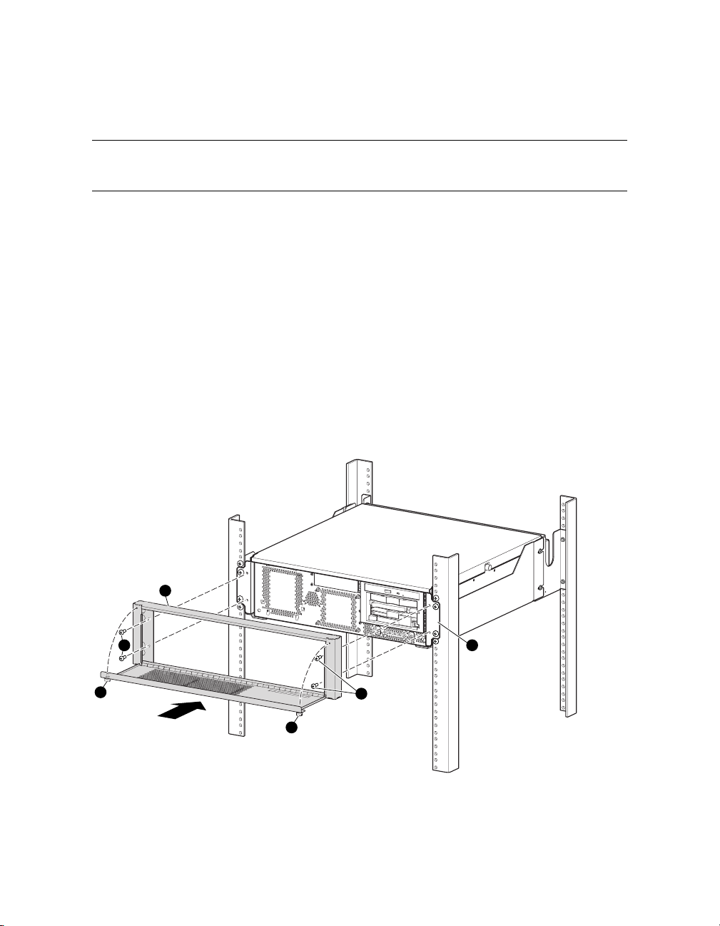
4.2 Removing and Replacing the Top Cover
You must remove the enclosure from its rack in order to remove the top cover. With
the top cover removed, you have access to virtually all the internal components.
Removing Cables and Front Bezel
1. Shut down the operating system, turn off system power by pressing the power switch on
the operator control panel, and attach your antistatic wrist strap.
2. Go to the rear of the cabinet, locate the back panel of the AlphaServer TS15 enclosure,
and disconnect both power connectors. Also, disconnect the ground cable and all other
cables from the enclosure.
3. As show in the next figure, loosen the thumbscrews
the four screws
o
that fasten the front bezel p to the enclosure’s face panel q.
Remove the bezel and set it aside.
Figure 4–1 Removing the Front Bezel
3
2
1
1
2
n
to open the front door. Remove
4
MR0564
Installing and Configuring Options 4-3
Page 90
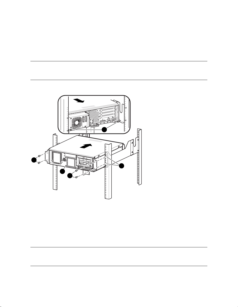
Removing the System Enclosure
1. As shown in Figure 4–2, remove the four screws
rack. Note the location of the mounting holes
n
that fasten the enclosure o to the
p
.
CAUTION: The enclosure is heavy, not tethered, and will fall out if not handled carefully.
Grasp it firmly with both hands before sliding it from or into the rack.
Figure 4–2 Removing the Enclosure from the Rack
A
1
B
A
2
1
2
1
B
4
3
MR0563
2. Slide the enclosure from the rack and place it on a tabletop.
n
3. As shown in Figure 4–3, remove the three M4 screws
enclosure and fully loosen the three captive screws
on the hinged side p of the
o
on the other side.
4. Rotate the enclosure so that the hinged edge is slightly overhanging the tabletop.
q
Lift up the captive screw side
the hinged side. Lift the cover straight up
of the cover and disengage the tabs from the slots on
r
and set it on the tabletop.
NOTE: Notice the quick reference labels on the inside of the top cover. The labels provide
detailed information about the system.
4-4 hp AlphaServer TS15 Owner's Guide
Page 91

Figure 4–3 Removing the Top Cover
1
2
5
3
A
4
MR0642
Installing and Configuring Options 4-5
Page 92

Replacing the Top Cover
CAUTION: Avoid injury by keeping fingers away from the right (captive screw) edge of
the cover.
1. Rotate the enclosure so its left side slightly overhangs the edge of the tabletop.
2. Referring to preceding Figure 4–3, engage the four tabs on the left side of the cover
with the slots on the lower left side of the enclosure. Lower the cover until the right
edge rests on the enclosure.
3. While pushing the left side of the cover against the enclosure, push the right (captive
screw) edge down until it is fully seated.
n
4. As shown in the preceding figure, install the three M4 screws
the enclosure and tighten the three captive screws
Reinstalling the Enclosure
o
on the other side to 13-15 ft.-lb.
on the hinged side of
1. Slide the enclosure into the rack. Be sure to align the rear tabs
shown in Figure 4–2.
n
2. As shown in the same figure, insert the four screws
the rack.
3. As show in Figure 4–1, install the front bezel by inserting the four screws
enclosure’s face panel
4. Go to the rear of the cabinet, locate the back panel of the AlphaServer TS15 enclosure,
and connect the ground cable and all other cables to the enclosure. Connect both power
connectors. (Refer to Figure 1-15 for details.)
5. Turn on system power by pressing the power switch on the operator control panel. Boot
the operating system.
q
. Close the front door and tighten the thumbscrews n.
that fasten the enclosure o to
q
with the rack slides as
o
into the
4-6 hp AlphaServer TS15 Owner's Guide
Page 93
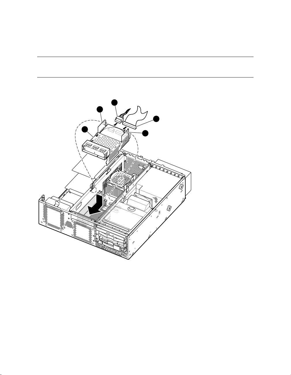
4.3 Replacing the Disk in Center Internal Storage Bay
The center internal storage bay provides a disk drive as optional storage. Refer to the
following figures and procedures when replacing this disk drive.
Figure 4–4 Accessing the Center Internal Storage Bay
4
2
3
1
2
4
MR0629
Removing the Center Internal Storage Bay
4. Shut down the system and remove the top cover as explained in Section 4.2.
5. As shown in the preceding figure, pull the two spring-loaded pull pins
the storage bay
n
and slide the unit toward the back of the enclosure.
o
at the rear of
6. Lift the storage bay from the enclosure and turn it over.
Installing and Configuring Options 4-7
Page 94
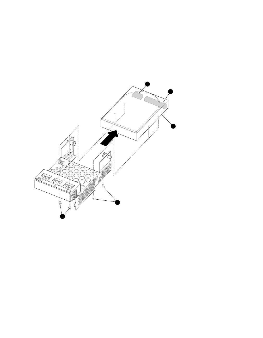
7. Remove the data cable
p
and power cable q from the rear of the storage bay and set
the storage bay aside.
8. Replace the disk drive as described on the following pages.
Figure 4–5 Replacing the Disk in the Center Internal Storage Bay
2
1
4
3
3
MR0532
Replacing the Disk in the Center Internal Storage Bay
p
1. Remove the four screws
q
out.
from the bottom of the storage bay and slide the disk drive
9. Install the new disk drive and replace the bottom screws.
10. Referring to preceding Figure 4–4, connect the data cable
new disk drive
n
.
p
11. Slide the storage bay forward into the enclosure.
4-8 hp AlphaServer TS15 Owner's Guide
and power cable q to the
Page 95
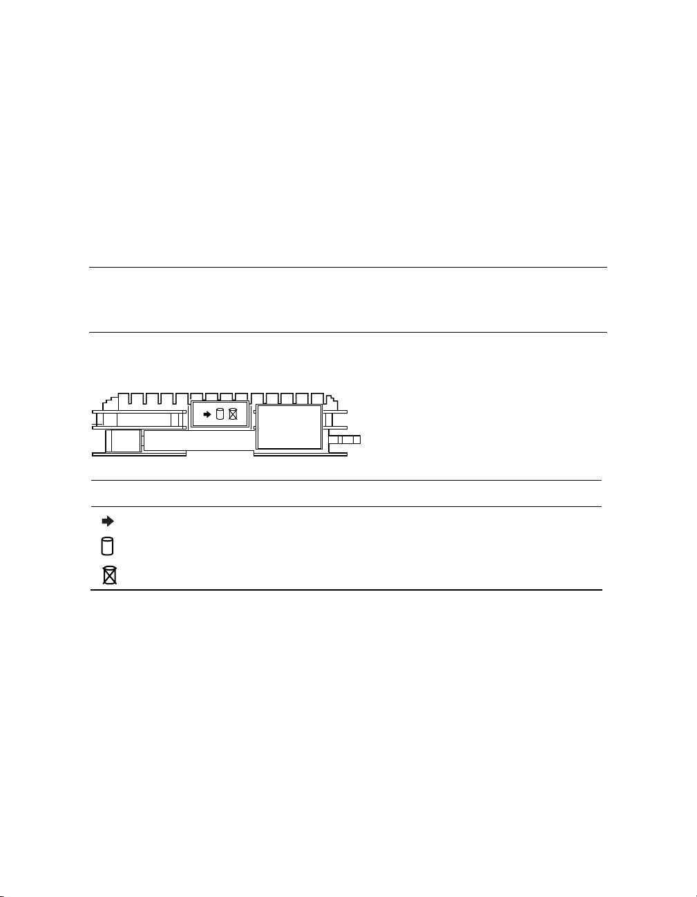
12. Pull the two spring-loaded pull pins
into place.
13. Replace the top cover and reassemble the system enclosure as explained at the end of
Section 4.2.
14. Turn on system power by pressing the power switch on the operator control panel. Boot
the operating system.
o
and lower the storage bay until the pins snap
4.4 Status LEDs on Front Access Drives
Storage drives in the optional front access storage cage provide three status LEDs that
display activity, power, and drive fault. The following figure shows the position and
purpose of these LEDs.
Figure 4–6 LEDs on the Front Access Drive (Front View)
MR0308B
LED Status
Green indicates activity.
Green indicates drive state.
Amber indicates drive state fault.
Installing and Configuring Options 4-9
Page 96
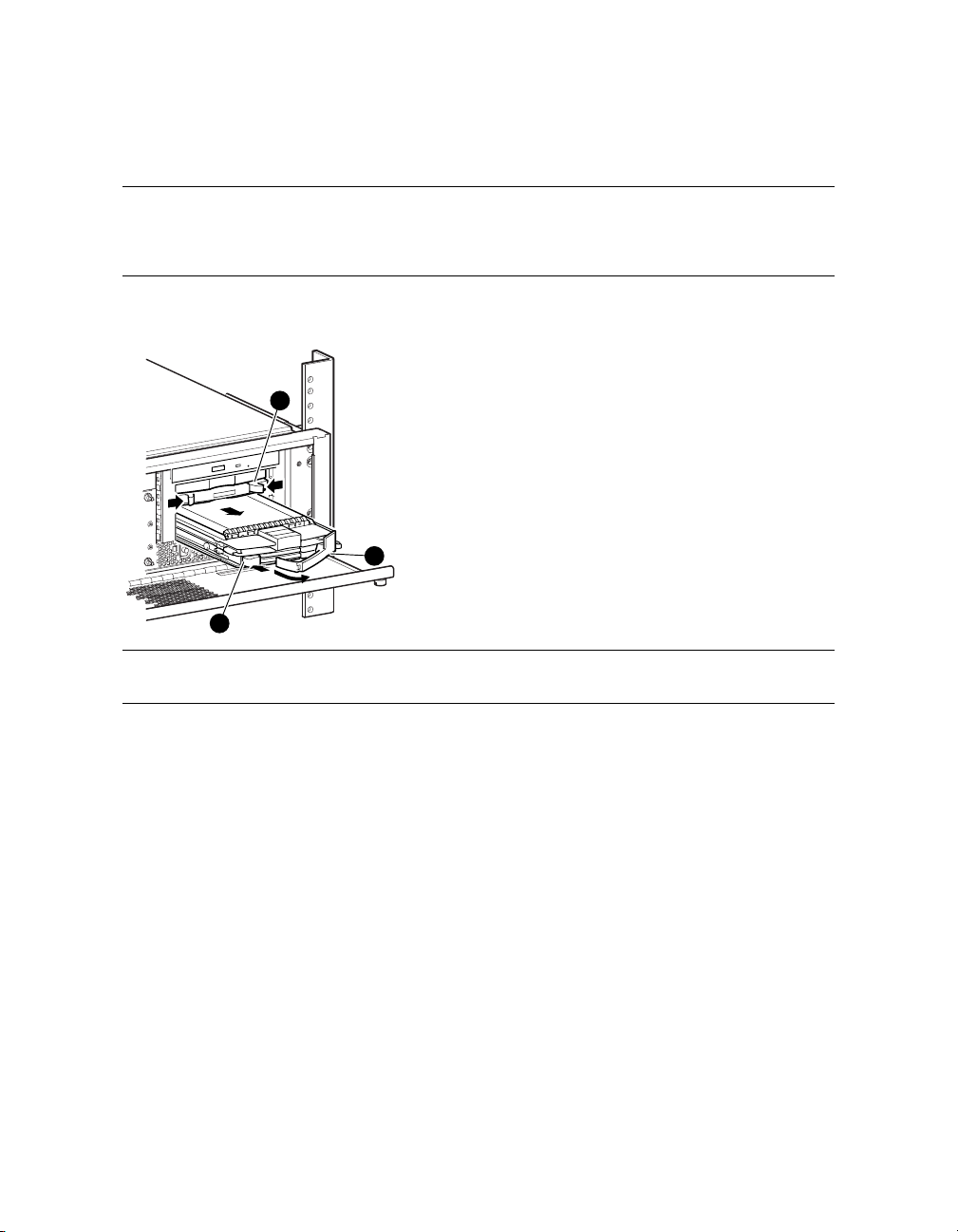
4.5 Replacing a Front Access Drive
If the system includes the optional front access storage cage, then one or two disk
drives or one tape drive may be installed, depending on the option originally installed.
Refer to the following information when replacing a front access disk or tape drive.
Figure 4–7 Replacing a Front Access Disk Drive
3
2
1
CAUTION: Before removing a drive, make sure that its activity LED is off.
Replacing a Front Access Disk Drive
1. Verify that the disk drive is not in use (the activity LED is off).
2. To remove the drive, press in the colored rubber button
3. Pull the handle
the cage. If only one disk drive is installed, a filler plate
4. Insert the new disk drive into the cage with the front handle
drive resting on top of the rail guides of the cage, slide the drive in until it stops.
5. Push the handle
Verification
You must enter the SRM and use the init and show device commands to verify that the
system sees the new drive.
4-10 hp AlphaServer TS15 Owner's Guide
Y
Y
MR0632
X
to release the handle.
forward to release the SCSI connection and then pull the drive from
p
fills the other drive slot.
o
fully opened. With the
to make the backplane connection and secure the drive in the cage.
Page 97
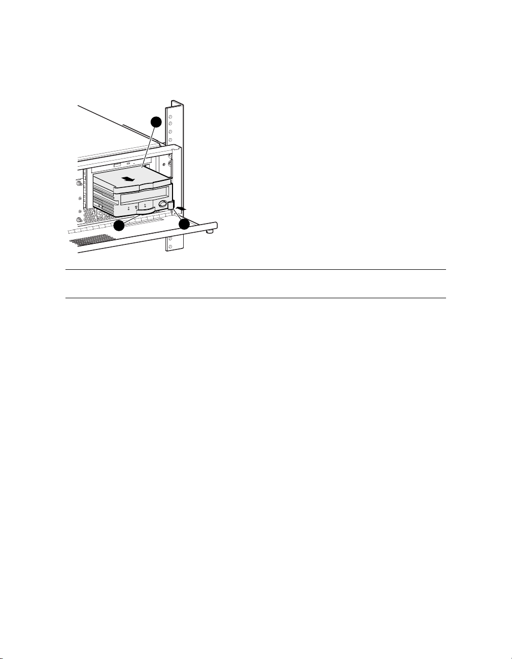
Figure 4–8 Replacing a Front Access Tape Drive
3
2
1
MR0658
CAUTION: Before removing a drive, make sure that its activity LED is off.
Replacing a Front Access Tape Drive
1. Verify that the tape drive is not in use (the activity LED is off).
n
2. To remove the drive, press the locking tab
3. Pull on the handle
Y
to remove the drive from the cage. A plastic filler p slides out
to the left to disengage the tape drive.
with the tape drive.
4. Snap the new plastic filler onto the new tape drive.
5. Insert the new tape drive into the cage. With the drive resting on top of the rail guides of
the cage, slide the drive in until it stops.
Y
6. Push the handle
to make the backplane connection. Verify that the locking tab n
snaps into place.
Verification
You must enter the SRM and use the init and show device commands to verify that the
system sees the new drive.
Installing and Configuring Options 4-11
Page 98
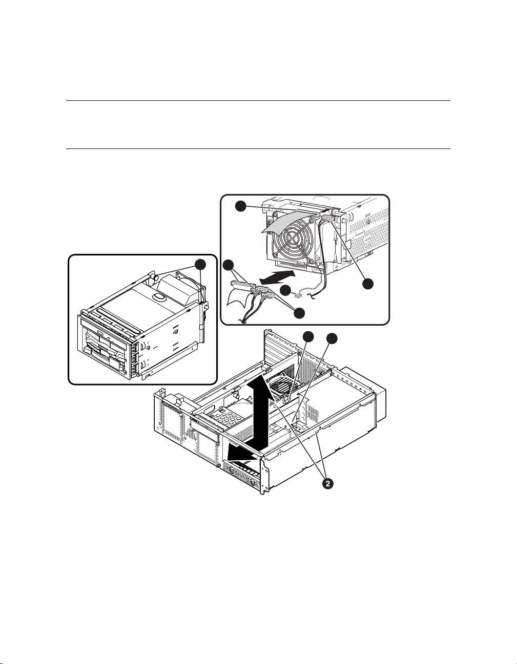
4.6 Accessing the Front Access Storage Cage
The front access storage cage is an optional component and the alternative to the
internal storage cage. You must remove this cage to access the bottom disk drive. Refer
to the following figure and procedure when removing this cage.
Figure 4–9 Accessing the Front Access Storage Cage
4
1
3
14
6
13
1
2
5
7
8
9
MR0631
4-12 hp AlphaServer TS15 Owner's Guide
Page 99

Accessing the Front Access Storage Cage
1. Shut down the system and remove the top cover as explained in Section 4.2.
2. Remove the IDE data cable
CD-RW drive.
3. Pull the two spring-loaded posts
Y
.
4. Pull the storage cage back, pivot the rear end up, and remove it from the enclosure.
Turn the cage over to access the remaining cables.
5. Remove the SCSI cable
6. Disconnect the fan cable
_
top slot area
The cage is now completely disconnected.
7. Reverse the procedure (steps 6 to 2) to install the storage cage.
15. Replace the top cover and reassemble the system enclosure as explained in the end of
Section 4.2.
16. Turn on system power by pressing the power switch on the operator control panel. Boot
the operating system.
, except the fan cable, which is routed through the lower slot area `.
[
and power cable \ from the back of the slimline DVD-
X
inward so that they come out of the receiving holes
Z
and power cable ^.
]
from the motherboard. All the cables are routed through the
Installing and Configuring Options 4-13
Page 100
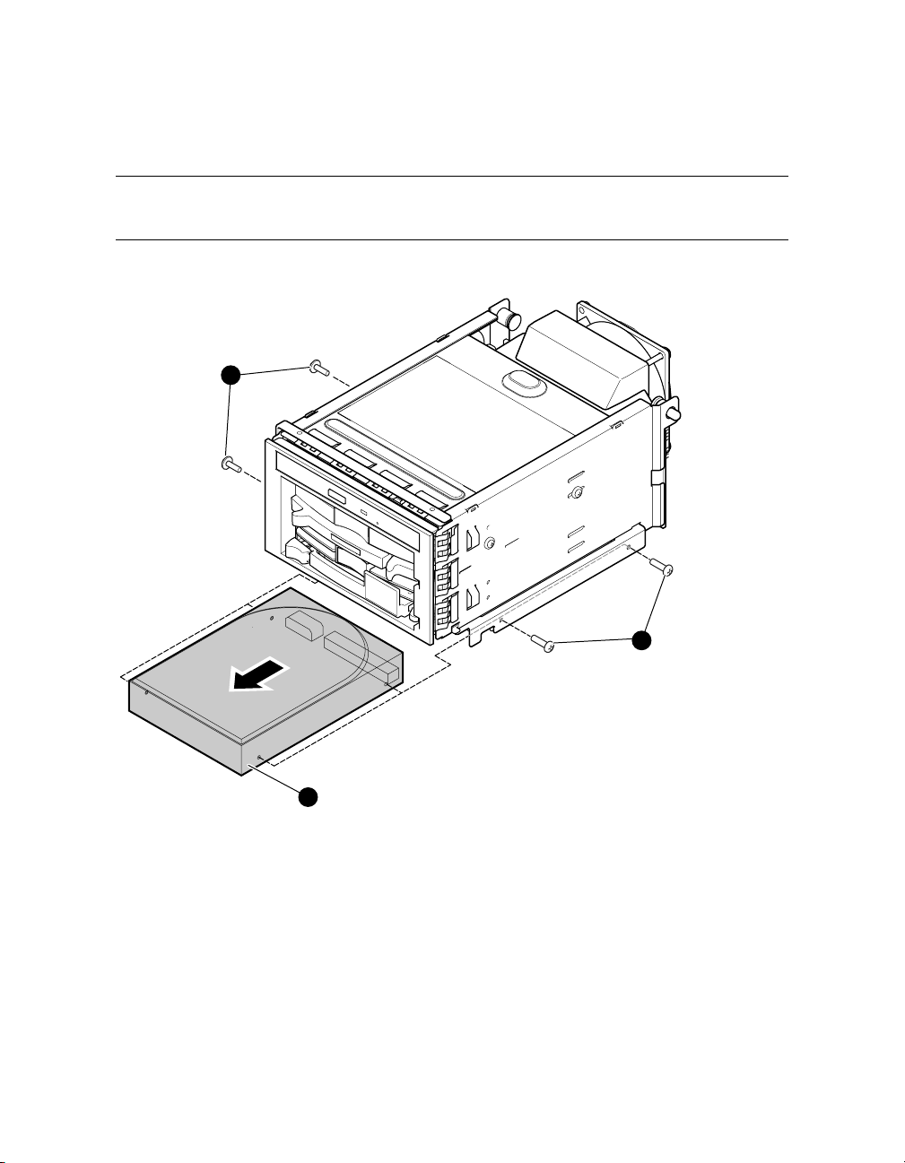
4.7 Replacing Bottom Drive – Front Access Cage
The bottom disk drive provides optional storage. Refer to the following figure and
procedure when replacing a bottom drive.
Figure 4–10 Replacing Bottom Drive – Front Access Storage Cage
1
1
2
4-14 hp AlphaServer TS15 Owner's Guide
MR0593A
 Loading...