

Page 1

Hewlett-Packard Company
AlphaServer GS80
Upgrade Manual
Order Number: EK-GSR80-UP. C01
This manual is for service providers of HP AlphaServer GS80
systems. It discusses system expansion and upgrade of an
original system with faster CPUs.
Page 2

August 2002
© 2002 Hewlett-Packard Company.
Portions of the software are © copyright Cimetrics Technology. UNIX is a trademark of The Open
Group in the United States and other countries. All other product names mentioned herein may be
trademarks of their respective companies.
HP shall not be liable for technical or editorial errors or omissions contained herein. The information
in this document is provided “as is” without warranty of any kind and is subject to change without
notice. The warranties for HP products are set forth in the express limited warranty statements
accompanying such products. Nothing herein should be construed as constituting an additional
warranty.
FCC Notice
This equipment generates, uses, and may emit radio frequency energy. The equipment has been type
tested and found to comply with the limits for a Class A digital device pursuant to Part 15 of FCC
rules, which are designed to provide reasonable protection against such radio frequency interference.
Operation of this equipment in a residential area may cause interference in which case the user at his
own expense will be required to take whatever measures may be required to correct the interference.
Any modifications to this device—unless expressly approved by the manufacturer—can void the
user’s authority to operate this equipment under part 15 of the FCC rules.
Modifications
The FCC requires the user to be notified that any changes or modifications made to this device that are
not expressly approved by Hewlett-Packard Company may void the user's authority to operate the
equipment.
Cables
Connections to this device must be made with shielded cables with metallic RFI/EMI connector hoods
in order to maintain compliance with FCC Rules and Regulations.
Taiwanese Notice
Page 3

Japanese Notice
Canadian Notice
This Class A digital apparatus meets all requirements of the Canadian Interference-Causing Equipment
Regulations.
Avis Canadien
Cet appareil numérique de la classe A respecte toutes les exigences du Règlement sur le matériel
brouilleur du Canada.
European Union Notice
Products with the CE Marking comply with both the EMC Directive (89/336/EEC) and the Low
Voltage Directive (73/23/EEC) issued by the Commission of the European Community.
Compliance with these directives implies conformity to the following European Norms (in brackets are
the equivalent international standards):
EN55022 (CISPR 22) - Electromagnetic Interference
EN50082-1 (IEC801-2, IEC801-3, IEC801-4) - Electromagnetic Immunity
EN60950 (IEC950) - Product Safety
Warning!
This is a Class A product. In a domestic environment this product may cause radio interference in
which case the user may be required to take adequate measures.
Achtung!
Dieses ist ein Gerät der Funkstörgrenzwertklasse A. In Wohnbereichen können bei Betrieb dieses
Gerätes Rundfunkstörungen auftreten, in welchen Fällen der Benutzer für entsprechende
Gegenmaßnahmen verantwortlich ist.
Attention!
Ceci est un produit de Classe A. Dans un environnement domestique, ce produit risque de créer des
interférences radioélectriques, il appartiendra alors à l'utilisateur de prendre les mesures spécifiques
appropriées.
Page 4

Page 5

v
Contents
Preface ix
Chapter 1 Overview
1.1 The System............................................................................................1-2
1.2 GS80 Block Diagram............................................................................. 1-3
1.3 GS80 Physical Diagram........................................................................1-4
1.4 Cabinets ................................................................................................ 1-5
Chapter 2 System Upgrade
2.1 Installing a Power Subrack................................................................... 2-2
2.2 Installing the Second Drawer ............................................................... 2-4
2.2.1 Installing the Distribution Board Assembly .........................................2-6
2.2.2 Global Port, Clock, and Ground Connections........................................2-8
2.2.3 Power, Signal, and CSB Connections.................................................. 2-14
Chapter 3 PCI Box Installation
3.1 Installing a PCI Box.............................................................................. 3-2
3.1.1 Preparing the PCI Box for Installation................................................. 3-4
3.1.2 Preparing the Cabinet for PCI Box Installation ................................... 3-6
3.1.3 Installing the PCI Box and Making Cable Connections .......................3-8
3.2 Expander Cabinet Configurations ...................................................... 3-10
Chapter 4 System Power-Up
4.1 Control Panel Keyswitch....................................................................... 4-2
4.2 Installing the System Management Console ........................................ 4-4
4.3 Powering Up the System....................................................................... 4-5
4.4 Q-VET Installation Verification.......................................................... 4-14
4.4.1 Installing Q-VET................................................................................. 4-16
4.4.2 Running Q-VET................................................................................... 4-18
Page 6

vi
4.4.3 Reviewing Results of the Q-VET Run.................................................4-20
4.4.4 De-Installing Q-VET ........................................................................... 4-22
Appendix A GS80 Interconnection Diagram
Appendix B Upgrades Using B4166 and B4168CPUs
B.1 Upgrades Retaining Older CPUs..........................................................B-2
B.2 Upgrades Replacing Older CPUs..........................................................B-5
B.3 Changing the Clock Module Switch Settings........................................B-7
B.4 B4168 Compatibility Switch ...............................................................B-11
B.5 Verification..........................................................................................B-12
B.6 Replacing the System Cosmetics.........................................................B-13
Index
Examples
4–1 Power-Up Display ................................................................................. 4-5
B–1 Updating the Firmware ........................................................................B-5
Figures
1–1 A GS80 System...................................................................................... 1-2
1–2 GS80 Block Diagram (Two-Drawer System)......................................... 1-3
1–3 GS80 Physical Diagram (Two-Drawer System) .................................... 1-4
2–1 Installing the Power Subrack ...............................................................2-2
2–2 Installing Second Drawer...................................................................... 2-4
2–3 Installing the Distribution Board Assembly ......................................... 2-6
2–4 Cable Connections-1.............................................................................. 2-8
2–5 Cable Connections-2............................................................................ 2-11
2–6 Cable Connections-3............................................................................ 2-12
2–7 Cable Connections-4............................................................................ 2-13
2–8 Power, Signal, and CSB Connections.................................................. 2-14
3–1 PCI Box ................................................................................................. 3-2
3–2 Preparing the PCI Box for Installation.................................................3-4
3–3 Preparing the Cabinet for Installation ................................................. 3-6
3–4 Cable Connections of the PCI Box ........................................................3-8
3–5 Configurations Based on the Starlight Storage Shelf......................... 3-10
Page 7

vii
3–6 Configurations Based on the StorageWorks Storage Shelf................. 3-11
3–7 Mounting Locations for the Starlight Storage Shelves....................... 3-12
3–8 Mounting Locations for the StorageWorks Storage Shelves............... 3-13
3–9 Mounting Locations for the PCI Box................................................... 3-14
3–10 Mounting Locations for the Memory Channel .................................... 3-15
4–1 Operator Control Panel......................................................................... 4-2
A–1 GS80 Interconnection Diagram.............................................................A-2
B–1 Installing a CPU ...................................................................................B-2
B–2 System Clock Switch Packs...................................................................B-7
B–3 Accessing the Clock Module..................................................................B-8
B–4 Setting the B4168 Compatibility Switch.............................................B-11
B–5 GS80 Cabinet ......................................................................................B-13
Tables
1
1–1 Cabinet Models and Power Requirements............................................1-5
3–1 PCI Box Mounting Hardware ...............................................................3-3
4–1 Keyswitch Functions on the Control Panel........................................... 4-3
B–1 Comparisons of CPUs............................................................................B-3
B–2 Comparisons of System Drawers ..........................................................B-4
Page 8

Page 9

ix
Preface
Intended Audience
This manual is for service providers of HP AlphaServer GS80 systems.
Document Structure
This manual uses a structured documentation design. Topics are organized into
small sections, usually consisting of two facing pages. Most topics begin with an
abstract that provides an overview of the section, followed by an illustration or
example. The facing page contains descriptions, procedures, and syntax
definitions.
This manual has four chapters and two appendixes.
• Chapter 1, Overview, provides a conceptual introduction to the system.
• Chapter 2, System Upgrade, discusses the requirements for the upgrade
of a one-drawer system to a two-drawer system.
• Chapter 3, PCI Box Installation, describes how to install a PCI box. A
section at the end of the chapter gives the configuration rules for an
expander cabinet.
• Chapter 4, System Power-Up, describes how to power up the system and
when to boot the operating system.
• Appendix A, GS80 Interconnection Diagram, shows how the
components of the GS80 system are interconnected.
• Appendix B, Upgrades Using B4166 and B4168 CPUs, discusses how to
upgrade an original (blue cabinet) system to a new (black cabinet) system
that operates with faster CPUs.
Page 10

x
Documentation Titles
Table 1 HP AlphaServer GS80 Documentation
Title Order Number
QA–6GAAA–G8 AlphaServer GS80/160/320 Documentation Kit
EK–GS320–UG AlphaServer GS80/160/320 User’s Guide
EK–GS320–RM AlphaServer GS80/160/320 Firmware Reference Manual
EK–GSPAR–RM AlphaServer GS80/160/320 Getting Started with Partitions
EK–GS320–IN AlphaServer GS160/320 Installation Guide
EK–GSR80–IN AlphaServer GS80 Installation Guide
AG–RKSW*–BE AlphaServer GS80/160/320 User Information CD
QA–6GAAB–G8 AlphaServer GS80/160/320 Service Documentation Kit
EK–GS320–SV AlphaServer GS80/160/320 Service Manual
EK–GS320–RM AlphaServer GS80/160/320 Firmware Reference Manual
AG–RKSZ*–BE AlphaServer GS80/160/320 Service Information CD
EK–GSCON–IN AlphaServer GS80/160/320 System Management Console
Installation Guide
EK–GSCON–UG AlphaServer GS80/160/320 System Management Console
Installation and User Guide
EK–GS320–UP AlphaServer GS160/320 Upgrade Manual
EK–GSR80–UP AlphaServer GS80 Upgrade Manual
EK–GS320–SP AlphaServer GS80/160/320 Site Preparation
Information on the Internet
Visit the HP Web site at www.compaq.com/alphaserver for service tools and
more information about the
AlphaServer GS80 system.
Page 11

Overview 1-1
Chapter 1
Overview
The AlphaServer GS80 systems form the low end of the family of highperformance server platforms GS80/160/320 designed for enterprise-level
applications. Like the GS160/320 systems, the GS80 systems are distinguished
by their versatility and high degree of expandability.
This chapter gives an overview of the GS80 system with a block diagram and a
physical diagram. Section 1-4 lists the system and expander cabinets with
their power requirements.
The GS80 system is contained in a single cabinet. It is a drawer-based system
consisting of one or two drawers. Each drawer contains one QBB with up to
four CPU modules and up to four memory modules. In a two-drawer system a
distribution board connects the two QBBs through their global ports.
The system cabinet of the GS80 also contains the power supplies and
accommodates one PCI box, a storage shelf (optional), and the OCP (operator
control panel). An expander cabinet can house additional PCI boxes and
storage shelves.
Page 12

1-2 AlphaServer GS80 Upgrade Manual
1.1 The System
The GS80 systems come in two Alpha microprocessor configurations:
4-processor and 8-processor. Each group of four microprocessors,
along with memory and I/O modules, is designed into a single quad
building block (QBB) that is housed in a drawer. Thus the systems
are also designated as one-drawer and two-drawer.
Figure 1–1 A GS80 System
PK-0635-99
digital
LA75
Companion Printer
AlphaServer GS80
Page 13

Overview 1-3
System Upgrades
A system upgrade is achieved in three ways:
• Adding a second drawer to a single drawer system
• Adding a storage device to the single-drawer system
• Adding an expander cabinet to accommodate any additional I/O devices
This manual details the procedures for the addition of a second drawer to the
system cabinet as well as the installation of a PCI box. The addition of an
expander cabinet is discussed in the AlphaServer GS80 Installation Guide
(EK-GSR80-IN).
CPU Upgrades
In this upgrade, the original 4-Mbyte B-cache B4125 CPUs are replaced with
faster B4166 CPUs (8-Mbyte B-cache) or B4168 CPUs (16-Mbyte B-cache); or
B4166 or B4168 CPUs are added to the existing system. The original system
has the following characteristics:
1. The system cabinet is blue.
2. The system drawer(s) supports 4 Mbytes of CPU B-cache.
3. The system contains 731 MHz B4125 CPUs only.
4. The system runs on a 9.6 ns clock.
The addition of B4166 or B4168 CPUs to an existing system with B4125 CPUs
results in a partial upgrade. In a fully upgraded system, all system drawers
would support the size of the CPU’s B-cache, and all B4125 CPUs would be
replaced with B4166 or B4168 CPUs.
The rules and procedures for upgrading an original system are discussed in
Appendix B.
Page 14

1-4 AlphaServer GS80 Upgrade Manual
1.2 GS80 Block Diagram
Figure 1–2 shows a block diagram of a two-drawer GS80 system. A
distribution board makes the interconnect between the two drawers
(QBBs) through their global ports.
Figure 1– 2 GS80 Block Diagram (Two-Drawer System)
PCI Box
PCI Box
System Drawer 1
System Drawer 2
CPU
MEM
I/O GP
CPU CPU CPU
Switch
MEMMEMMEM
Distribution
Board
CPU
MEM
I/O GP
CPU CPU CPU
Switch
MEMMEMMEM
PCI Box
PCI Box
PK-0630-99
Page 15

Overview 1-5
1.3 GS80 Physical Diagram
Figure 1–3 shows the physical diagram of a two-drawer GS80 system
with a PCI box and an optional storage unit.
Figure 1– 3 GS80 Physical Diagram (Two-Drawer System)
PK1280
Operator
Control
Panel
PCI Box
Storage
(optional)
System Drawer 1
System Drawer 2
Power Supplies
AC Input Boxes
Page 16

1-6 AlphaServer GS80 Upgrade Manual
1.4 Cabinets
Table 1–1 shows the model number of cabinets and power
requirements for GS80 systems operating in various electrical
environments.
Table 1– 1 Cabinet Models and Power Requirements
Cabinet Model Power Requirement
System Cabinet H9A20-CA
(U.S./Canada)
115-127V
System Cabinet H9A20-CB
(Europe)
200-240V
System Cabinet H9A20-CC
(U.S./Canada/Japan)
200-240V
Expander Cabinet H9A20-AA
(U.S./Canada)
115-127V
Expander Cabinet H9A20-AB
(Europe)
200-240V
Expander Cabinet H9A20-AC
(U.S./Canada/Japan)
200-240V
Page 17

System Upgrade 2-1
Chapter 2
System Upgrade
To upgrade a one-drawer system to a two-drawer system, you must:
• Install the power subrack for the second drawer
• Install the second drawer
Page 18

2-2 AlphaServer GS80 Upgrade Manual
2.1 Installing a Power Subrack
Install the power subrack first, then install the second drawer. Figure
2–1 shows how to install the power subrack.
Figure 2–1 Installing the Power Subrack
PK-0543-99
3
5
1
2
2
4
Page 19

System Upgrade 2-3
The shipping box of the power subrack assembly contains the following items:
• Subrack power supply assembly
• Two base support brackets, right-hand and left-hand
• Mounting kit hardware consisting of two M6 screws, six M5 screws, and
four M6 nuts
Refer to Figure 2–1 and install the power subrack into the cabinet as follows:
1. Insert an M6 screw
on the left-hand base support bracket (74-52913-01)
through the appropriate hole on the left-hand rail of the cabinet front so
that the bracket is inside the cabinet and the three securing holes are lined
up with the cabinet rail holes. Secure with an M6 nut.
2. Secure the back of the base support bracket to the rear cabinet rail hole
with an M6 screw and nut
.
3. Repeat steps 1 and 2 for the right-hand base support bracket (74-52913-02).
Tighten all the nuts with a hex wrench.
4. Slide the power subrack assembly onto the base support brackets and push
it into the cabinet.
5. Attach the power subrack assembly to the front of the cabinet with two M6
screws and nuts on each side
.
6. Route the power cables
from the subrack over the rail inside the cabinet
and then over to the bottom AC input box. Plug the power cables into the
AC input box.
7. Connect the power and signal cables
to the connectors on the rear panel
of the power subrack. Also, connect the OCP power cable to the subrack.
8. Install the power supplies.
You have now installed the power subrack into the cabinet. Next, you must
install the second drawer and make the cable connections.
Page 20

2-4 AlphaServer GS80 Upgrade Manual
2.2 Installing the Second Drawer
Figure 2–2 shows a system with two drawers. To install the second
drawer you must first prepare the system cabinet. Insert the drawer
referring to Figures 2-2 to 2-7.
Figure 2–2 Installing Second Drawer
1
Left
Bracket
Right
Bracket
2
3
PK3219
Page 21

System Upgrade 2-5
Refer to Figure 2–2 and install the second drawer as follows:
1. Install the front mounting brackets
and rear brackets
to the slides.
Leave rear brackets slightly loose. Locate hole 28 on the left rail and hole
29 on the right rail. Ensure that the holes have U-nuts and fasten the left
and right mounting brackets for the slides.
2. Mount the left side external track to the rails using two M6 screws
. Do
the front end first, then the rear end. Tighten mounting screws. Repeat for
the right side external track, but leave loose for proper alignment with
drawer slides.
3. Pull out the slide rails all the way until they lock. Make sure that the ball
bearing races on the external slide rails are positioned forward. Lift the
drawer (two persons needed) and carefully engage the internal rails on the
drawer with the external slide rails on the cabinet. Carefully slide the
drawer into the cabinet while making sure that the drawer rails engage
with the bearings.
4. Slide the drawer in and ensure that the loose right slide has engaged
correctly with the mating track. Tighten the right slide mounting screws.
5. Test that the drawer is installed properly by sliding it in and out of the
cabinet. Then, push the drawer all the way into the cabinet.
You must now install the distribution board assembly and make the following
cable connections:
• Global port cables
• Clock module power and signal harness
• Clock module coaxial cable
Page 22

2-6 AlphaServer GS80 Upgrade Manual
2.2.1 Installing the Distribution Board Assembly
Remove the placeholder bracket and insert the distribution board
assembly from the rear of the cabinet. Fasten it to the upper and lower
drawers. See Figure 2–3.
Figure 2–3 Installing the Distribution Board Assembly
PK3220
1
2
Page 23

System Upgrade 2-7
Refer to Figure 2–3 and install the distribution board assembly as follows:
1. Pull the top drawer out of the cabinet and remove the placeholder bracket
. Push the drawer back in.
2. Repeat step 1 on the lower drawer. Discard the placeholder brackets.
3. At the rear of the cabinet, push both drawers out about ten inches. Insert
the distribution board assembly from the rear of the cabinet and fasten it to
the upper and lower drawers
. The upper part is fastened with two M4
screws and the lower part with two captive screws. Note the guide pins and
mount the assembly to the upper drawer first. Do not tighten screws.
Ensure that lower captive screws are aligned and engaged to lower drawer.
If alignment of captive fasteners is not possible, loosen the eight M6 slide
mounting screws of one drawer and adjust for proper alignment. Once
alignment is made, tighten all screws and torque M6 screws to 6.9 Newtonmeters and M4 screws to 2 Newton-meters. Do not torque captive fasteners.
Page 24

2-8 AlphaServer GS80 Upgrade Manual
2.2.2 Global Port, Clock, and Ground Connections
Refer to Figure 2–4 to Figure 2–7 in making the global port, clock, and
ground connections.
Figure 2–4 Cable Connections-1
(FRONT VIEW)
A0
B0
B1
A1
1
2
3
PK3221
Page 25

System Upgrade 2-9
Refer to Figures 2-4 to 2-7 and make cable connections from the drawers to the
distribution board assembly. Do the lower drawer first.
1. Loosen captive fasteners on the distribution board assembly and extend the
lower drawer.
2. Remove drawer cover to assemble and route cables.
3. Remove the CPU and memory modules near the back left corner of the
drawer. Then, remove the two screws that hold the clock compartment
cover and remove the cover. Next, remove the plastic clock compartment
shield.
4. Attach global cables marked A1 and B1 to backplane connectors marked A0
and B0, and route through clamp and chassis cutout
.
5. Route male end of power harness through rear cutout and secure unused
female connector with clamp
.
6. Route coax cable and power harness through chassis cutout
. Reinstall
the clock compartment shield and the clock compartment cover removed
earlier. Reinstall the CPU and memory modules and reattach the drawer
cover.
Page 26

2-10 AlphaServer GS80 Upgrade Manual
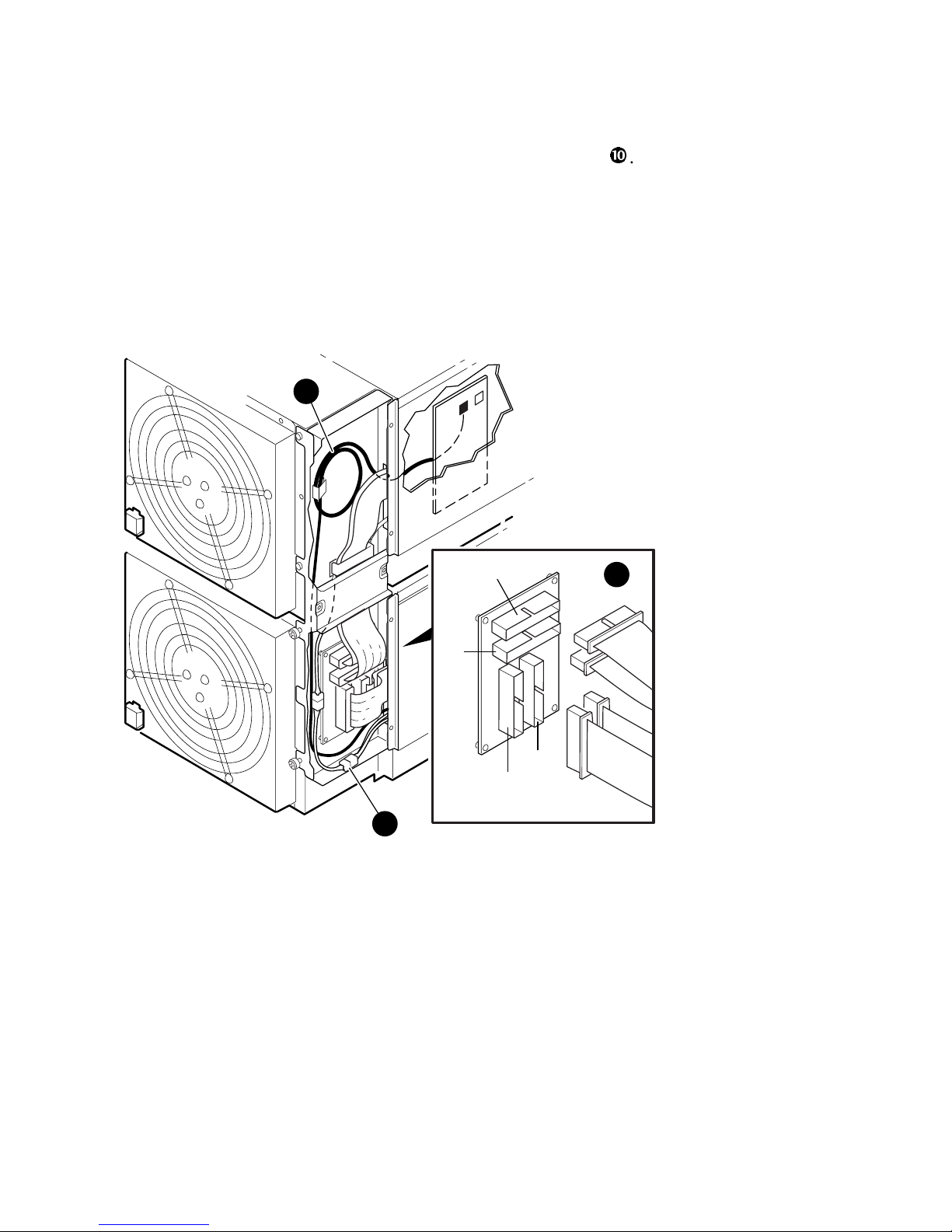
7. Carefully pull out the upper drawer while keeping the cables from the lower
drawer out of the way to protect them from any damage by the distribution
board assembly
(see Figure 2–5). Ensure that the distribution board
assembly is engaged with the lower drawer. Tighten captive fasteners.
8. Remove the CPU and memory modules near the back left corner of the
drawer. Then, remove the two screws that hold the clock compartment
cover and remove the cover. Next, remove the plastic clock compartment
shield.
9. Attach global ports marked A0 and B0 to the connectors on the backplane
labeled A0 and B0. Route the power harness loose female connector and
global cables from the upper drawer to the connectors in the distribution
board assembly
. Fold cables such that they route flat under the bracket
and attach without twist to the distribution board.
NOTE: Figure 2–4 does not show global cables being routed through the inner
chassis cable clamp.
10. Connect the power harness plug from the lower drawer to the power
harness receptacle of the upper drawer
(see Figure 2–6). The bottom
drawer receptacle and clock module are not used.
11. Route the coax cable from the lower drawer through the distribution board
assembly and the upper drawer rear cutout and connect it to the clock
module of the upper drawer. Coil excess cable into no less than a 3-inch
diameter loop through the clamp in the distribution board assembly
.
Install shield and clock compartment cover with screws.
Page 27

System Upgrade 2-11
Figure 2– 5 Cable Connections-2
4
5
PK3222
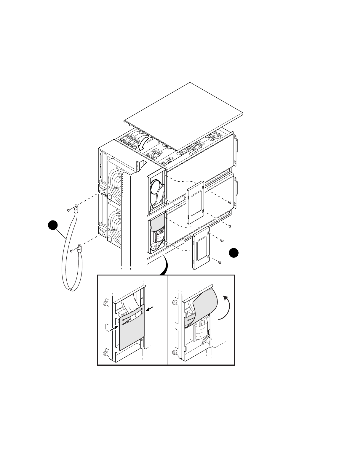
12. Connect the global port cables of the upper and lower drawers
to the
distribution board. Attach the plastic shield to cable B0 before plugging in
its connector. Then, fold the shield up to protect the global port cables from
the metal flanges.
13. Put the two covers on the distribution board assembly. Insert the tabs of
the distribution board assembly covers through the chassis slots, close the
covers, and fasten them to the chassis
with screws. (see Figure 2–7).
14. In the upper drawer, reinstall the CPU and memory modules. Next,
reattach the drawer cover and push both drawers into the cabinet. Fasten
them with the screws.
Page 28
2-12 AlphaServer GS80 Upgrade Manual
15. Install the ground strap to tie the drawers together
. Attach one end of
the ground strap to the power connector block on each drawer using one of
the existing mounting screws.
Figure 2– 6 Cable Connections-3
A0
B0
A0
B0
6
7
8
PK3223
Page 29
System Upgrade 2-13
Figure 2– 7 Cable Connections-4
FOLD
9
PK3224
10
Page 30
2-14 AlphaServer GS80 Upgrade Manual
2.2.3 Power, Signal, and CSB Connections
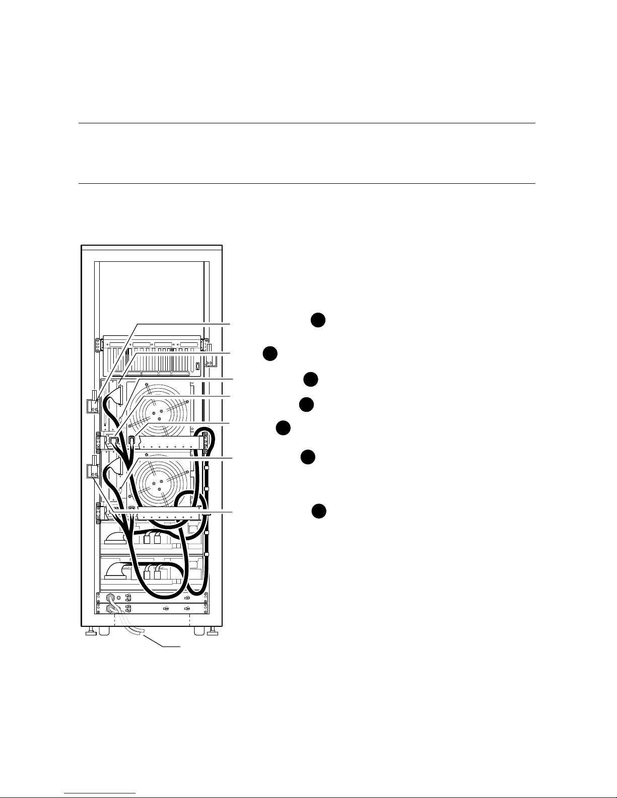
After you have installed the second drawer, make power/signal
connections between the power subrack and the drawer. Connect the
drawer to the CSB (console serial bus). See Figure 2– 8.
Figure 2– 8 Power, Signal, and CSB Connections
To Main AC Power Source
3
2
3
2
1
1
1
Power
Signals
CSB Junction Block
CSB Connection
CSB Connection
CSB Junction Block
Fan Power
/Signals
48V/48RTN
VAUX/VAUXRTN
PK3217A
Page 31

System Upgrade 2-15
Make the following cable connections to complete the installation of the second
drawer:
• Connections from the power subrack to the AC input box (if not made
already)
• Power signals to the drawer
• 48V/48RTN; Vaux/VauxRTN connections to the drawer
• Fan power/signals to the drawer
• CSB connections
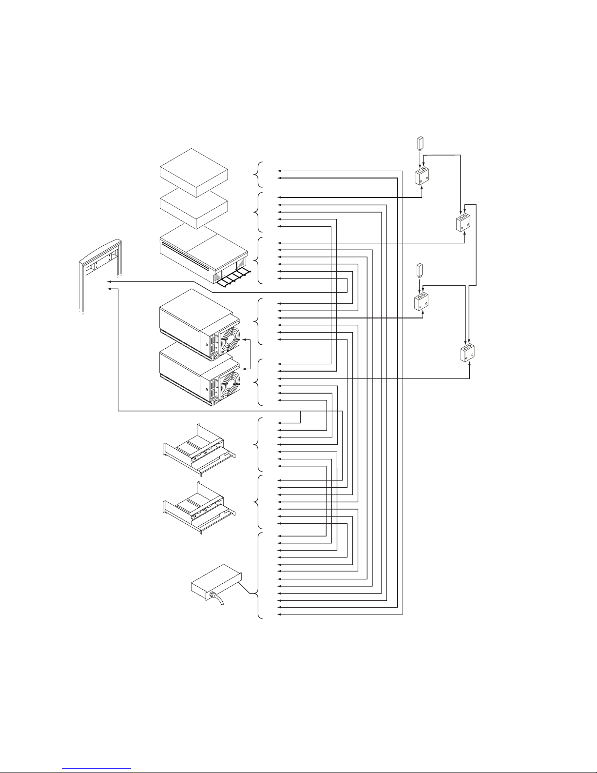
Refer to Appendix A for a wiring diagram illustrating the above connections.
Make sure that the CSB (console serial bus) between the J9 connector of the
master PCI box and the J6 connector of the drawer is properly connected and
terminated at both ends.
Proceed as follows:
1. Attach the power and signal cables from the power subrack to the new
drawer
. Route the cables as needed and attach the cables to the frame
with cable ties.
2. Attach the cable management bracket to the rear of the cabinet behind the
new drawer. Use two M6 screws on each side of the bracket to fasten it to
the cabinet frame where the drawer slide rails are attached.
3. Attach the CSB junction block to the side of the cabinet frame near the new
drawer
(Figure 3-4 shows details on CSB junction block attachment).
Then, attach the CSB cable from this junction block to the drawer
. Now,
connect the new CSB junction block to the existing junction block with
twisted-pair cable. Be sure to terminate any unused connections on the
junction blocks.
Make any hose cable connections from the local I/O riser ports on the drawers to
the remote risers in the PCI box.
The GS80 upgrade is complete. Turn on the system and verify the operation of
the new drawer.
Page 32

Page 33

PCI Box Installation 3-1
Chapter 3
PCI Box Installation
This chapter gives the procedures for the installation of a PCI box. Procedures
are applicable for the installation of the component in any location.
Page 34
3-2 AlphaServer GS80 Upgrade Manual
3.1 Installing a PCI Box
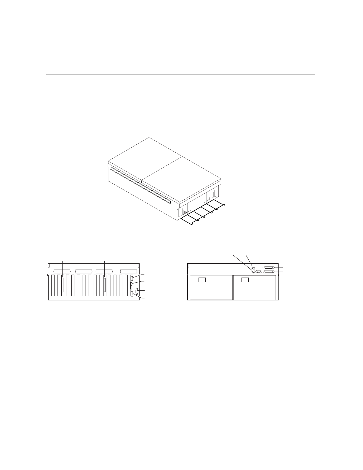
Unpack the shipping box and note its contents. Figure 3–1 shows the
PCI box.
Figure 3–1 PCI Box
Rear View
Front View
PK-0517-99
J-13
J-12
J-11
J-10
J-9
J-5
J-6
J-7
J-4
J-2
J-1
J-3
J-15 J-14
Page 35

PCI Box Installation 3-3
The shipping box contains the following items:
PCI box (BA54A-AA)
Mounting hardware kit (CK-BA54A-AA)
Table 3–1 lists the items in the PCI box mounting hardware (CK-BA54A-AA).
Table 3–1 PCI Box Mounting Hardware
Part Number Description CK-BA54A-AA
70-33596-01 Latch assembly 1
74-53016-01 Plate, strike 1
74-52544-01 Through cable 1
74-53597-01 Bracket, shipping 2
74-52428-01 Bracket, slide, front mounting (RH) 4
74-60022-01 Bracket, adapter, mounting 1
12-45925-01 Conn., adapter, molded (2) RJ4 1
12-45926-01 Conn., term., molded, 8 POS., MOD 1
17-04736-01
Wire harness assembly, 2TWP (2), 8
POS. MOD
1
17-04936-01
Cable assembly, mold, shld., 4TWP,
(2) 9
1
17-00083-03 Pwr cord term., 3-14 SJT 125V 108I 1
17-00442-18 Pwr cord term., 9’ LGG 15A 1
90-09984-19 Screw, SEMs, M4 x 0.7 x 8 mm 6
90-40346-01 Nut, hex metric, M4, CS, ZNC, HXW 6
90-09984-18 Screw, SEMs, M5 x 0.8 x 12 mm 18
90-07786-04 Nut, U-nut M5 18
90-40347-01
Screw, Mach, M4, TRS, 10 mm,
XRCS, CSZ
8
Page 36
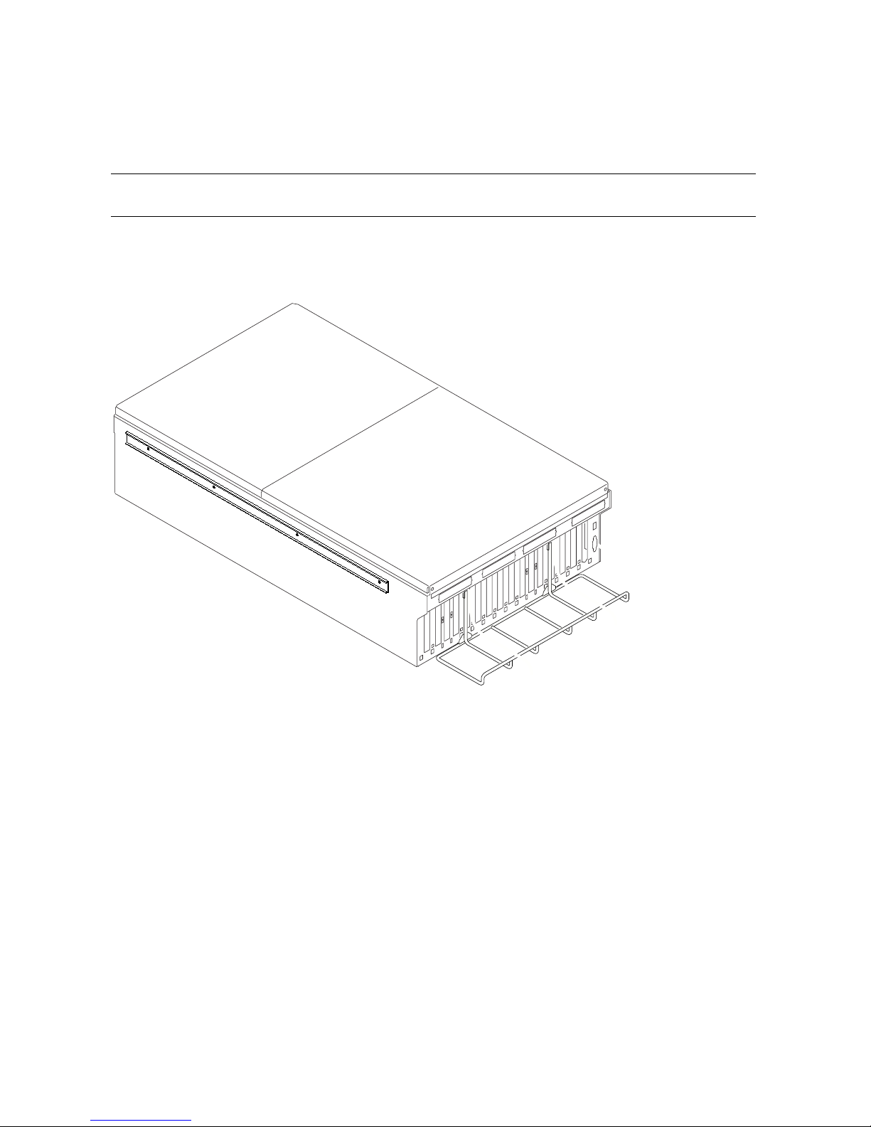
3-4 AlphaServer GS80 Upgrade Manual
3.1.1 Preparing the PCI Box for Installation
Figure 3–2 shows how to prepare the PCI box for installation.
Figure 3–2 Preparing the PCI Box for Installation
PK-0558-99
Page 37

PCI Box Installation 3-5
Prepare the PCI box for installation as follows:
1. Slide the outer track of the mounting rail assembly of the PCI box all the
way out. Press on the retaining lever to release the outer track from the
assembly.
2. Repeat step 1 on the other side of the PCI box.
The next step is to mount the outer tracks to the cabinet rails.
Page 38
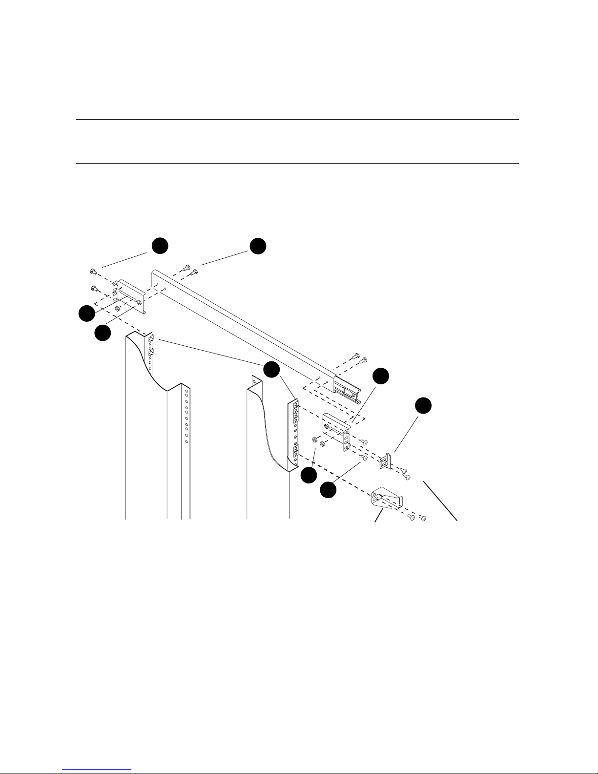
3-6 AlphaServer GS80 Upgrade Manual
3.1.2 Preparing the Cabinet for PCI Box Installation
Figure 3–3 shows how to prepare the cabinet for the PCI box
installation.
Figure 3–3 Preparing the Cabinet for Installation
PK-0559-99
4
2
3
1
5
1
2
6
5
Front
Rear
Shipping Bracket
Page 39

PCI Box Installation 3-7
Prepare the cabinet for installation as follows:
1. Select the location in the system cabinet or expander cabinet where the PCI
box is to be installed. Refer to the configuration rules given in Section 3.2.
2. Attach the two track mounting brackets (P/N 7452428-01)
to the two
ends of the outer track bracket with two M4 x 6 truss head screws for each
bracket
. The front track mounting bracket has an insert for
alignment. Tighten the two screws in the front bracket but leave the other
screws loose for later adjustment and tightening on the rear bracket. Do not
use insert to mount the rear bracket. Do the same on the second outer track
bracket.
CAUTION: It is very important to have the brackets loose until the PCI box is
mounted on the rails. Tightening the track mounting bracket at
this stage will cause difficulty and may result in jamming when
sliding the PCI box into the cabinet later in the procedure.
3. Locate the pattern of four holes on the selected area in the cabinet where
the PCI box is to be installed.
4. Place U-nuts on each of the four holes in the back cabinet rail and two Unuts on the two outermost holes in the front cabinet rail
.
5. Align the mounting rail brackets with the front and rear of the cabinet rails
and attach the mounting rail bracket to the cabinet rails with two M5
screws on the outermost holes of each mounting rail bracket
.
6. Mount the second rail on the other side of the cabinet following steps 3 to 5
above.
7. Attach the snap latch retainer bracket
to the rear rail mounting bracket
and the cabinet rail at the inner holes of the 4-hole pattern using two M5
screws. Ensure that the snap latch retainer bracket is aligned properly to
engage with the plastic latch to be placed on the PCI box after mounting.
Repeat this step at the opposite side of the PCI box.
The cabinet is ready for the installation of the PCI box.
Page 40
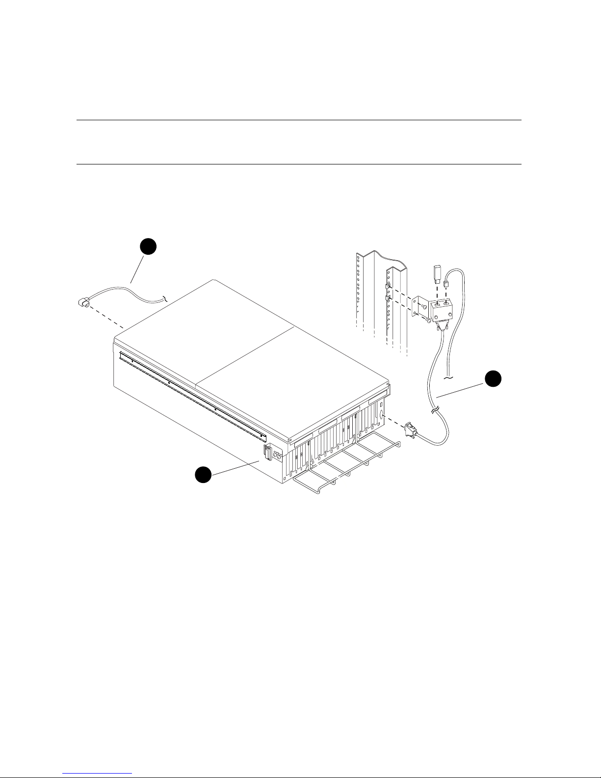
3-8 AlphaServer GS80 Upgrade Manual
3.1.3 Installing the PCI Box and Making Cable Connections
Install the PCI box and make the cable connections. Figure 3– 4 shows
how to connect the PCI box power cable and module cables.
Figure 3– 4 Cable Connections of the PCI Box
PK-0560-99
2
1
3
Page 41

PCI Box Installation 3-9
CAUTION: Proper alignment during the insertion of the PCI box in the cabinet
is critical. Two people are needed to lift the PCI box and slide it
gently onto the ball bearing track. Any mishandling or
misalignment at this stage could damage the hardware and result
in jamming.
Install the PCI box as follows:
1. Lift the PCI box and gently insert the rear sides of the inner tracks fastened
on the sides of the PCI box into the outer ball bearing tracks attached to the
cabinet. Visually align the track to the bearings and slide the PCI box all
the way in maintaining steady alignment until fully engaged. Slide the PCI
box out and in again to ensure free movement on the track. Tighten the
screws mounting the brackets to the cabinet rails.
2. Attach the latching bracket to the side of the PCI box
using two M4
screws (see Figure 3–4). Since you may need to adjust these screws later, do
not tighten them at this point. Repeat this step at the opposite side of the
PCI box.
3. Push the PCI box gently into the cabinet. The plastic latches should engage
with the latch retainer brackets on the cabinet. When this happens, you
should hear a latching click and the PCI box should sit snug and firm in the
cabinet. If the PCI box does not latch into place, pull it out and adjust the
position of the latching brackets. You may need to make these adjustments
a couple of times before a successful latching occurs.
4. Attach the power cable
to J1 for an 8-processor system and to J7 of the
first AC input box. If there is redundant power, then attach J2 to J8.
Attach the console serial bus (CSB) cable
to the J9 connector on the PCI
box.
The installation of the PCI box is complete.
Page 42
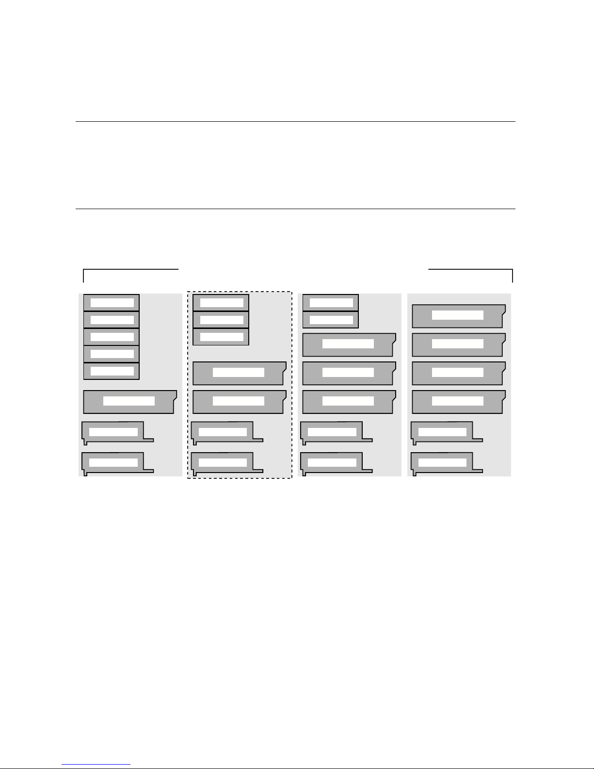
3-10 AlphaServer GS80 Upgrade Manual
3.2 Expander Cabinet Configurations
The expander cabinet provides space for additional I/O components
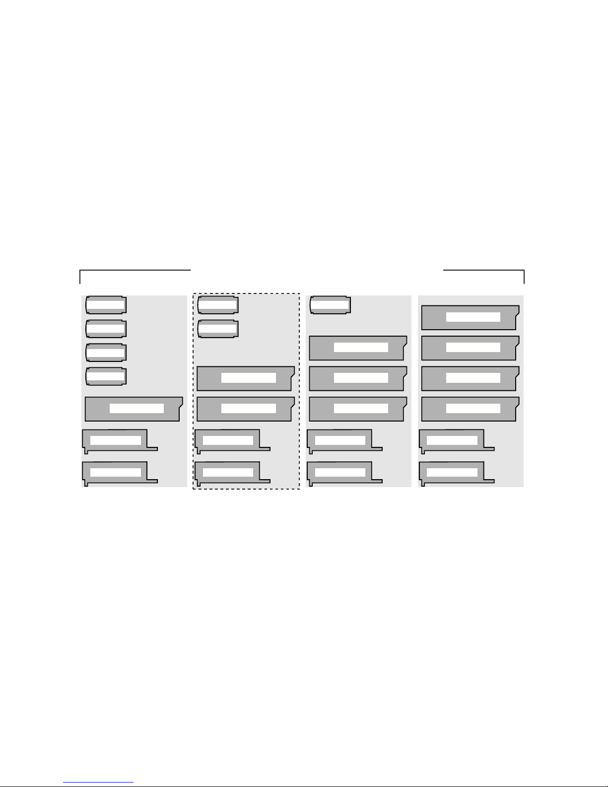
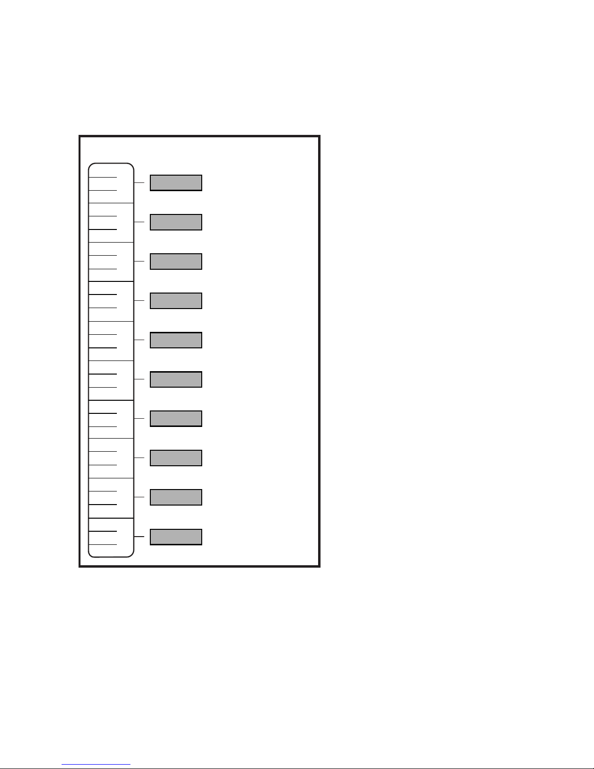
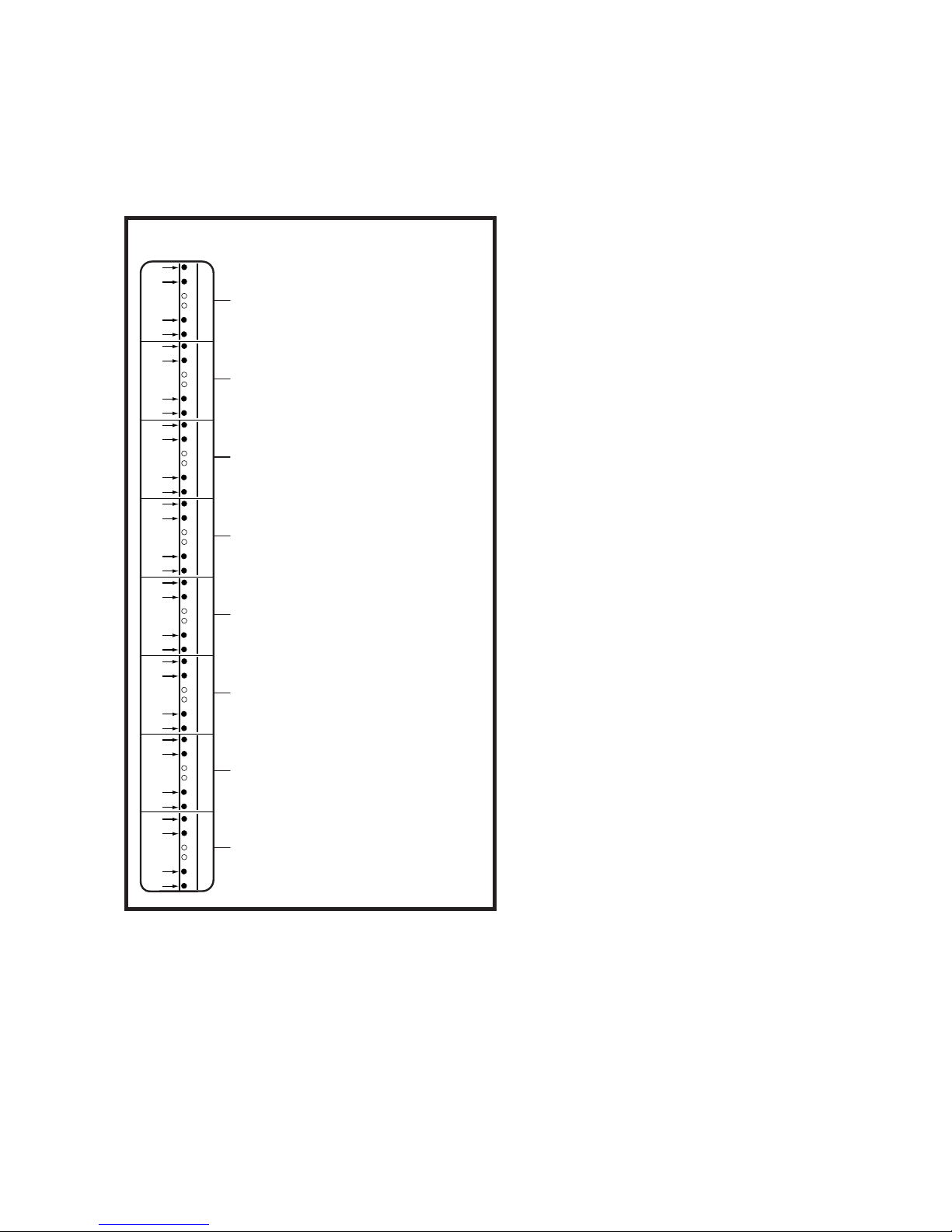
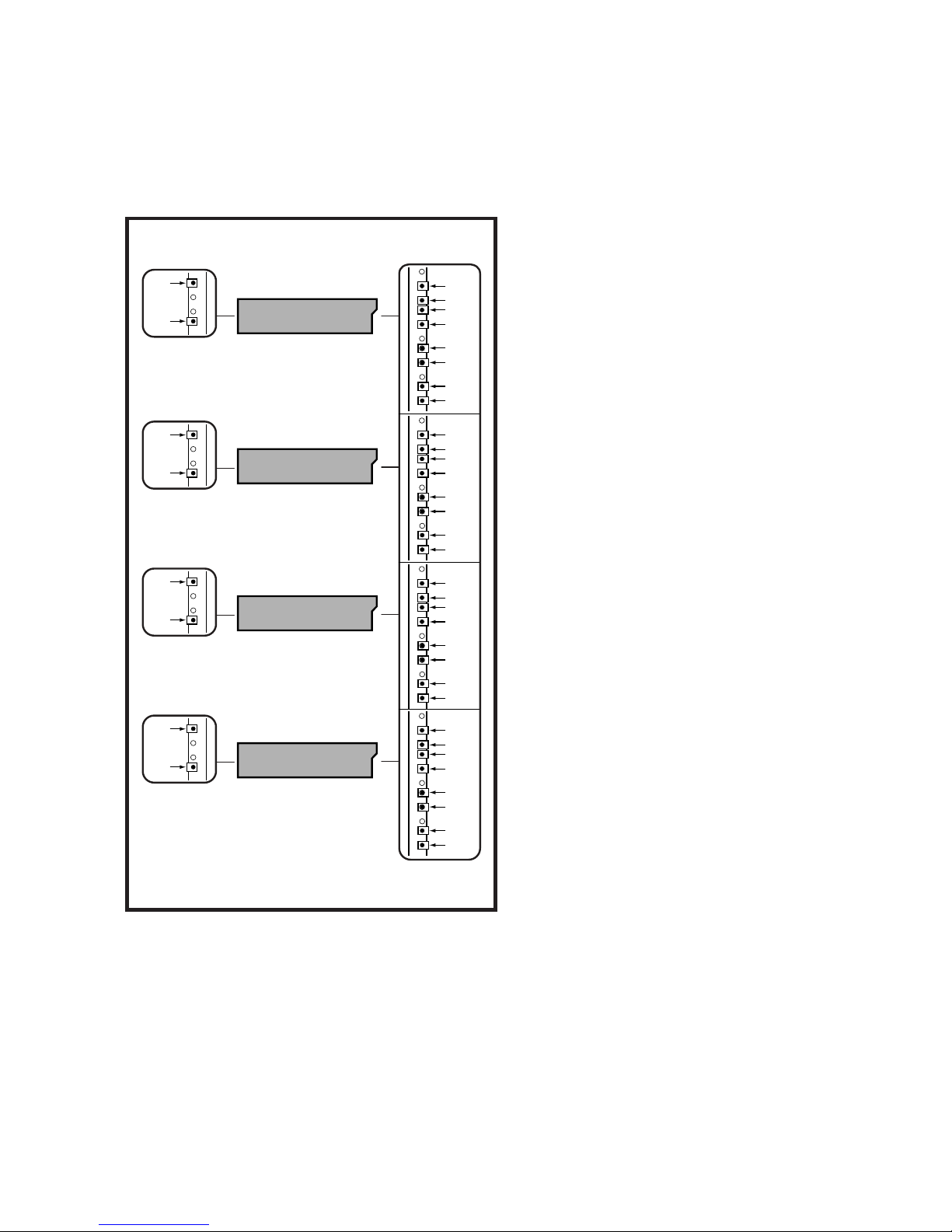
and the memory channel adapter. Figure 3– 5, Figure 3– 6, and Figure 3–
7 show various configurations for the expander cabinet. Figure 3– 7,
Figure 3– 8, Figure 3– 9, and Figure 3– 10 show the locations in the
expander cabinet where the I/O devices are mounted.
Figure 3– 5 Configurations Based on the Starlight Storage Shelf
Dual AC Cord - Starlight Configurations
Starlight (1)
Starlight (2)
Starlight (3)
Starlight (4)
Starlight (5)
BA54A PCI (1)
Default Configuration
Starlight (1)
Starlight (2)
Starlight (3)
BA54A PCI (1)
BA54A PCI (2)
Starlight (1)
Starlight (2)
BA54A PCI (1)
BA54A PCI (2)
BA54A PCI (3)
BA54A PCI (1)
BA54A PCI (2)
BA54A PCI (3)
BA54A PCI (4)
Mem. Ch. (2)
Mem. Ch. (1)
Mem. Ch. (2)
Mem. Ch. (1)
Mem. Ch. (2)
Mem. Ch. (1)
Mem. Ch. (2)
Mem. Ch. (1)
PK0547-00
Page 43
PCI Box Installation 3-11
The expander cabinet is used for additional PCI boxes and storage devices. In
addition, the expander cabinet holds two memory channel adapters for the PCI
boxes. The expander cabinet is shipped with a default configuration but can be
built to order as shown by other configurations. Figure 3–5, Figure 3–6, and
Figure 3–7 show the various configurations available for the expander cabinet
and the placement order of the I/O devices. Figure 3–7, Figure 3–8, Figure 3–9,
and Figure 3–10 show the locations in the expander cabinet where the I/O
devices are mounted.
Figure 3– 6 Configurations Based on the StorageWorks Storage Shelf
Dual AC Cord - BA356 Configurations
BA54A PCI (1)
BA356 (1)
BA356 (2)
BA356 (3)
BA356 (4)
BA54A PCI (1)
BA356 (1)
BA356 (2)
Default Configuration
BA54A PCI (2)
BA54A PCI (1)
BA356 (1)
BA54A PCI (2)
BA54A PCI (3)
BA54A PCI (1)
BA54A PCI (2)
BA54A PCI (3)
BA54A PCI (4)
Mem. Ch. (2)
Mem. Ch. (1)
Mem. Ch. (2)
Mem. Ch. (1)
Mem. Ch. (2)
Mem. Ch. (1)
Mem. Ch. (2)
Mem. Ch. (1)
PK0548-00
Page 44
3-12 AlphaServer GS80 Upgrade Manual
Figure 3– 7 Mounting Locations for the Starlight Storage Shelves
Starlight - Mounting Locations
Use DS-SE2UK-RM
Use DS-SE2UK-RM
Mounting Hardw
Mounting Hardw
are
are
to Mount Units in
to Mount Units in
Designated "U"
Designated "U"
Locations
Locations
("U" 31)
("U" 29)
("U" 30)
Front Rails
("U" 28)
("U" 26)
("U" 27)
("U" 25)
("U" 23)
("U" 24)
("U" 22)
("U" 20)
("U" 21)
("U" 19)
("U" 17)
("U" 18)
("U" 16)
("U" 14)
("U" 15)
("U" 13)
("U" 11)
("U" 12)
("U" 10)
("U" 8)
("U" 9)
("U" 7)
("U" 5)
("U" 6)
("U" 34)
("U" 32)
("U" 33)
Starlight
1
Starlight
2
Starlight
3
Starlight
4
Starlight
5
Starlight
6
Starlight
7
Starlight
8
Starlight
9
Starlight
10
Mount Stor
Mount Stor
age Shelv
age Shelv
es
es
so that the F
so that the F
ront Surf
ront Surf
aces
aces
are at or Near the F
are at or Near the F
ront
ront
Mounting Rails
Mounting Rails
.
PK0549-00
Page 45
PCI Box Installation 3-13
Figure 3– 8 Mounting Locations for the StorageWorks Storage Shelves
(Use BA35X-RK
(Use BA35X-RK
Mounting Hardw
Mounting Hardw
are)
BA356
1
BA356 - Hole Locations
Front Rails
BA356
2
BA356
3
BA356
4
BA356
5
BA356
6
BA356
7
BA356
8
15
14
11
10
27
26
23
22
39
38
35
34
51
50
47
46
63
62
59
58
75
74
71
70
87
86
83
82
99
98
95
94
PK0550-00
Page 46
3-14 AlphaServer GS80 Upgrade Manual
Figure 3– 9 Mounting Locations for the PCI Box
(50)
(49)
(48)
(47)
(43)
(42)
(80)
(77)
(65)
(62)
(50)
(47 )
(65)
(64)
(63)
(62)
(57)
(56)
(80)
(79)
(78)
(77)
(72)
(71)
BA54A PCI Box - Hole Locations
Front Rails
Rear Rails
PCI Box
4
CSB Mounting Holes
CSB Mounting Holes
.
(Mounts on Rear/Right Rail Only).
(Mounts on Rear/Right Rail Only).
PCI Box
3
PCI Box
2
(60)
(59)
*
*
(45)
(44)
*
*
(75)
(74)
*
*
*
(35)
(34)
(33)
(32)
(27)
(26)
(35)
(32 )
PCI Box
1
(Location for single unit)
(30)
(29)
*
*
PK0552-00
Page 47
PCI Box Installation 3-15
Figure 3– 10 Mounting Locations for the Memory Channel
Memory Channel - Hole Locations
Front Rails
Memory Channel
2
(25)
(26)
(27)
(29)
Rear Rails
(25)
(26)
(27)
Memory Channel
1
(10)
(11)
(12)
(14)
(10)
(11)
(12)
Use Memor
Use Memor
y Channel 2
y Channel 2
Rac
Rac
kmount Kit 2T
kmount Kit 2T
-MA
-MA
VRK
VRK
PK0551-00
Page 48

Page 49

System Power-Up 4-1
Chapter 4
System Power-Up
This chapter tells how to power up the system and what happens upon
power-up. Sections include:
• Control Panel Keyswitch
• Installing the System Management Console
• Powering Up the System
• Q-VET Installation Verification
Page 50
4-2 AlphaServer GS80 Upgrade Manual
4.1 Control Panel Keyswitch
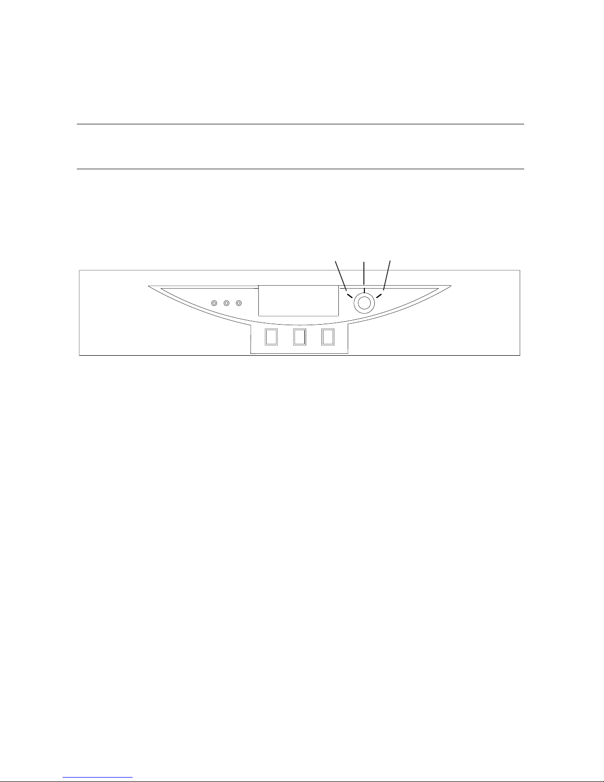
The operator control panel (OCP) keyswitch has three positions: Off,
On, and Secure. Figure 4–1 shows the OCP keyswitch.
Figure 4–1 Operator Control Panel
PK-0621A-99
Off On
Secure
Page 51

System Power-Up 4-3
Table 4–1 explains the functions selected by the keyswitch.
Table 4–1 Keyswitch Functions on the Control Panel
Keyswitch Position Function
Off System is powered off and cannot be
powered on remotely.
On System is powered on and can be
remotely powered on or powered off.
Secure System is powered on and cannot be
remotely powered on or off.
Refer to the AlphaServer GS80/160/320 User’s Guide or the AlphaServer
GS80/160/320 Service Manual for functional descriptions of all control panel
components.
Page 52

4-4 AlphaServer GS80 Upgrade Manual
4.2 Installing the System Management Console
Before you power up the system, you must install the system management console (SMC). Steps to be followed in installing the SMC are
listed below. The procedures to install the SMC are fully detailed in
the AlphaServer GS80/160/320 System Management Console Installation
Guide.
Steps to Install the SMC
1. Set up the SMC PC.
2. Install the SMC terminal server in the GS80 system.
3. Connect the terminal server to the power source.
4. Turn circuit breakers on but keep the keyswitch on Off.
5. Cable the PC to the terminal server and set up parameters.
6. Verify communication from the console to the system control manager.
You are now ready to power up the system.
WARNING: Before you power up the system, inspect the modules
for any visible sign of water condensation on the heatsinks, DC-to-DC
converters, and the CPUs. Due to the large mass of the system,
condensation may occur during transfer from a cold to a warm
environment. Allow time for the condensation to evaporate completely. DO NOT power the system up if you notice any indication of
condensation.
Page 53

System Power-Up 4-5
4.3 Powering Up the System
To power up the system, first turn the circuit breakers in all cabinets
on, then set the keyswitch on the OCP to the On position. Example 4– 1
shows a sample console display on power-up. See the AlphaServer
GS80/160/320 Service Manual or the AlphaServer GS80/160/320 User’s
Guide for explanations of the power-up display.
Example 4– 1 Power-Up Display
SCM_E0> power on
Powering on PCI Box 0
Powering on PCI Box 1
QBB-0 Powering ON
~I~ Testing OCP Switch- passed
Power ON Phase INIT
QBB-1 Powering ON
QBB-2 Powering ON
QBB-3 Powering ON
~I~ SCM powered via PBM
SCM_E0>
QBB0 now Testing Step-0
QBB1 now Testing Step-0
QBB2 now Testing Step-0
QBB3 now Testing Step-0
~I~ SCMe1 non-csb member while it tests & initializes its
Shared RAM
SCM_E0> .
~I~ QBB0/PSM30 SysEvent: QBB_INIT_CD1 Reg0:7AB3
Reg1:3FFF (test-0) (fmask/fts:8f)
.
~I~ QBB1/PSM31 SysEvent: QBB_INIT_CD1 Reg0:7AB3
Reg1:3FFF (test-0) (fmask/fts:8f)
~I~ QBB2/PSM32 SysEvent: QBB_INIT_CD1 Reg0:768F
Reg1:0FFF (test-0) (fmask/fts:8f)
~I~ QBB3/PSM33 SysEvent: QBB_INIT_CD1 Reg0:768F
Reg1:0FFF (test-0) (fmask/fts:8f)
Page 54

4-6 AlphaServer GS80 Upgrade Manual
Testing SIO Shared RAM(please wait)
Initializing shared ram
Shared RAM Initialized
Powering ON H-Switch
SCM_E0>
~I~ HSW4/HPM40 SysEvent: HS_INIT_CD1 Reg0:000F
Reg1:D581
Phase 0
~I~ Enable HS Links: 0f
~I~ QbbConf(gp/io/c/m)=0000bbff Assign=0f SQbb0=00 PQbb=00
SoftQbbId=0000ba98
~I~ SysConfig: 00 00 00 00 00 00 00 00 07 1f 07 9f 37 3f
37 9f
SCM_E0>
~I~ HSW4/HPM40 SysEvent: LINK0_ON Reg0:000F
Reg1:D581
~I~ HSW4/HPM40 SysEvent: LINK1_ON Reg0:010F
Reg1:D581
SCM_E0>
~I~ HSW4/HPM40 SysEvent: LINK2_ON Reg0:030F
Reg1:D581
SCM_E0>
~I~ HSW4/HPM40 SysEvent: LINK3_ON Reg0:070F
Reg1:D581
SCM_E0> ............
QBB0 now Testing Step-1
QBB1 now Testing Step-1
QBB2 now Testing Step-1
QBB3 now Testing Step-1
QBB0 now Testing Step-3
QBB1 now Testing Step-3
QBB2 now Testing Step-3
QBB3 now Testing Step-3..
QBB0 now Testing Step-5
QBB1 now Testing Step-5
QBB2 now Testing Step-4
QBB3 now Testing Step-4
QBB2 Step(s)-4 5 Tested
QBB3 Step(s)-4 5 Tested
Phase 1
Page 55

System Power-Up 4-7
QBB0 IO_MAP0: 0000A0C001333333
QBB1 IO_MAP1: 0000A1C101333333
QBB2 IO_MAP2: 0000000000000003
QBB3 IO_MAP3: 0000000000000003
~I~ QbbConf(gp/io/c/m)=0000bbff Assign=0f SQbb0=00 PQbb=00
SoftQbbId=0000ba98
~I~ SysConfig: 00 00 00 00 00 00 00 00 07 1f 07 9f 37 3f
37 9f
SCM_E0> .
QBB0 now Testing Step-7
QBB1 Step(s)-5 6 Tested
QBB2 Step(s)-5 6 Tested
QBB3 Step(s)-5 6 Tested
QBB0 now Testing Step-9..
QBB0 now Testing Step-A.
QBB0 now Testing Step-7
QBB0 now Testing Step-9..
QBB0 now Testing Step-A.
QBB0 now Testing Step-8
QBB0 now Testing Step-9..
QBB0 now Testing Step-A.
QBB0 now Testing Step-B.
Phase 2
QBB0 IO_MAP0: 0000A0C001333333
QBB1 IO_MAP1: 0000A1C101333333
QBB2 IO_MAP2: 0000000000000003
QBB3 IO_MAP3: 0000000000000003
~I~ QbbConf(gp/io/c/m)=0000bbff Assign=0f SQbb0=00 PQbb=00
SoftQbbId=0000ba98
~I~ SysConfig: 00 00 00 00 00 00 00 00 07 1f 07 9f 37 3f
37 9f
SCM_E0>
QBB0 now Testing Step-C
QBB1 now Testing Step-C
QBB2 now Testing Step-C
QBB3 now Testing Step-C..
Page 56

4-8 AlphaServer GS80 Upgrade Manual
Phase 3
~I~ QbbConf(gp/io/c/m)=0000bbff Assign=0f SQbb0=00 PQbb=00
SoftQbbId=0000ba98
~I~ SysConfig: 00 00 00 00 00 00 00 00 07 1f 07 9f 37 3f
37 9f
SCM_E0> .
QBB0 now Testing Step-D
QBB1 now Testing Step-D
QBB2 now Testing Step-D
QBB3 now Testing Step-D....
QBB0 IO_MAP0: 0000A0C001333333
QBB1 IO_MAP1: 0000A1C101333333
QBB2 IO_MAP2: 0000000000000003
QBB3 IO_MAP3: 0000000000000003
Phase 4
~I~ QbbConf(gp/io/c/m)=0000bbff Assign=0f SQbb0=00 PQbb=00
SoftQbbId=0000ba98
QBB0 unloading console across port0 from PCI Box-0
Console COM1 from master PCI Box-0
~I~ SysConfig: 00 00 00 00 00 00 00 00 07 1f 07 9f 37 3f
37 9f
Retrieving FRU information for Shared RAM...(please wait)
SCM_E0> .
QBB3 now Testing Step-E
QBB0 now Testing Step-E
QBB1 now Testing Step-E
QBB2 now Testing Step-E..
Power On Complete
Returning to system COM1 port
System Primary QBB0 : 0
System Primary CPU : 0 on QBB0
Par hrd/csb CPU Mem IOR3 IOR2 IOR1 IOR0 GP QBB Dir PS
Temp
QBB# 3210 3210 (pci_box.rio) Mod BP Mod 321
(:C)
(-) 0/30 PPPP P--P --.- --.- P0.1 P0.0 P P P P-P
28.0
Page 57

System Power-Up 4-9
(-) 1/31 PPPP --PP --.- --.- P1.1 P1.0 P P P P-P
32.0
(-) 2/32 PPPP P--P --.- --.- --.- --.- P P P -PP
29.0
(-) 3/33 PPPP ---P --.- --.- --.- --.- P P P -PP
30.0
HSwitch Type Cables76543210 Temp(:C)
HPM40 4-port ----PPPP 32.0
PCI Rise1-1 Rise1-0 Rise0-1 Rise0-0 RIO PS Temp
Cab7654 321 7654 321 10 21 (:C)
10 --L- --- ---- L-S ** PP 35.0
11 ---- --- ---- --S ** PP 34.5
OpenVMS PALcode V1.80-1, Tru64 UNIX PALcode V1.74-1
system = QBB0123 +HS
QBB0=CPU0123+Mem0 3+Dir+IOP+PCA01 +
GP (Hard QBB 0)
QBB1=CPU0123+Mem01 +Dir+IOP+PCA01 +
GP (Hard QBB 1)
QBB2=CPU0123+Mem0 3+Dir+IOP+PCA +
GP (Hard QBB 2)
QBB3=CPU0123+Mem0 +Dir+IOP+PCA +
GP (Hard QBB 3)
micro firmware version is T5.5
shared RAM version is 1.4
hose 0 has a standard I/O module
starting console on CPU 0
initialized idle PCB
initializing semaphores
initializing heap
initial heap 300c0
memory low limit = 1fc000
heap = 300c0, 1ffc0
initializing driver structures
initializing idle process PID
initializing file system
initializing timer data structures
Page 58

4-10 AlphaServer GS80 Upgrade Manual
lowering IPL
CPU 0 speed is 731 MHz
create dead_eater
create poll
create timer
create powerup
access NVRAM
QBB 0 memory, 3 GB
QBB 1 memory, 3 GB
QBB 2 memory, 3 GB
QBB 3 memory, 1 GB
total memory, 10 GB
copying PALcode to 10bffe0000
copying PALcode to 20bffe0000
copying PALcode to 303ffe0000
probe I/O subsystem
probing hose 0, PCI
probing PCI-to-ISA bridge, bus 1
bus 0, slot 1 -- pka -- QLogic ISP10x0
bus 0, slot 3 -- ewa -- DE500-BA Network Controller
bus 0, slot 15 -- dqa -- Acer Labs M1543C IDE
probing hose 1, PCI
probing hose 2, PCI
probing hose 3, PCI
bus 0, slot 5 -- pkb -- QLogic ISP10x0
probing hose 8, PCI
probing PCI-to-ISA bridge, bus 1
bus 0, slot 1 -- pkc -- QLogic ISP10x0
bus 0, slot 15 -- dqb -- Acer Labs M1543C IDE
probing hose 9, PCI
probing hose 10, PCI
probing hose 11, PCI
starting drivers
entering idle loop
starting console on CPU 1
initialized idle PCB
initializing idle process PID
lowering IPL
CPU 1 speed is 731 MHz
create powerup
starting console on CPU 2
initialized idle PCB
initializing idle process PID
lowering IPL
CPU 2 speed is 731 MHz
create powerup
Page 59

System Power-Up 4-11
starting console on CPU 3
initialized idle PCB
initializing idle process PID
lowering IPL
CPU 3 speed is 731 MHz
create powerup
starting console on CPU 4
initialized idle PCB
initializing idle process PID
lowering IPL
CPU 4 speed is 731 MHz
create powerup
starting console on CPU 5
initialized idle PCB
initializing idle process PID
lowering IPL
CPU 5 speed is 731 MHz
create powerup
entering idle loop
starting console on CPU 6
initialized idle PCB
initializing idle process PID
lowering IPL
CPU 6 speed is 731 MHz
create powerup
starting console on CPU 7
initialized idle PCB
initializing idle process PID
lowering IPL
CPU 7 speed is 731 MHz
create powerup
starting console on CPU 8
initialized idle PCB
initializing idle process PID
lowering IPL
CPU 8 speed is 731 MHz
create powerup
starting console on CPU 9
initialized idle PCB
initializing idle process PID
lowering IPL
CPU 9 speed is 731 MHz
create powerup
starting console on CPU 10
initialized idle PCB
initializing idle process PID
Page 60

4-12 AlphaServer GS80 Upgrade Manual
lowering IPL
CPU 10 speed is 731 MHz
create powerup
starting console on CPU 11
initialized idle PCB
initializing idle process PID
lowering IPL
CPU 11 speed is 731 MHz
create powerup
starting console on CPU 12
initialized idle PCB
initializing idle process PID
lowering IPL
CPU 12 speed is 731 MHz
create powerup
starting console on CPU 13
initialized idle PCB
initializing idle process PID
lowering IPL
CPU 13 speed is 731 MHz
create powerup
starting console on CPU 14
initialized idle PCB
initializing idle process PID
lowering IPL
CPU 14 speed is 731 MHz
create powerup
entering idle loop
starting console on CPU 15
initialized idle PCB
initializing idle process PID
lowering IPL
CPU 15 speed is 731 MHz
create powerup
initializing GCT/FRU at 1fc000
initializing pka pkb pkc ewa dqa dqb
environment variable mopv3_boot created
version V5.8-4667 May 4 2000 02:24:27
AlphaServer Console V5.8-4667, built on May 4 2000 at 02:24:27
P00>>>
Page 61

System Power-Up 4-13
The SRM console prompt (P00>>>) is displayed at the end of power-up.
This completes the power-up initialization/testing sequence. The operating
system can be booted and installed from the SRM console prompt.
Follow instructions given in the AlphaServer GS80/160/320 User’s Guide to:
• Set boot options
• Boot and install Tru64 UNIX
• Boot and install OpenVMS
You can now run Q-VET to verify the system installation (Section 4.4).
Page 62

4-14 AlphaServer GS80 Upgrade Manual
4.4 Q-VET Installation Verification
Run the latest Q-VET released version to verify the system
installation.
Compaq recommends running the latest Q-VET released version to verify that
hardware on Tru64 UNIX and OpenVMS systems is installed correctly and is
operational. Q-VET is the Qualification Verifier Exerciser Tool that is used by
product engineers to exercise systems under development. Q-VET does not
verify the operating system configuration.
If the system has been partitioned, Q-VET must be installed and run
separately on each partition to verify the complete installation. Compaq
Analyze must be installed on the operating system prior to running Q-VET.
You must always obtain the latest revision of Q-VET from the Q-VET Web
site— the latest Q-VET release, information, Release Notes and documentation
are located at http://chump2.mro.cpqcorp.net/qvet/.
Q-VET is not FISed on
new systems or included on the quarterly firmware CD. (It is distributed on the
Tools Unplugged CD at http://phxmcs.phx.dec.com/mcstools_request.htm, but
that version may not be the latest.)
CAUTION:
Do not install the Digital System Verification Software (DECVET) on GS80,
GS160, or GS320 systems.
Non-IVP Q-VET scripts verify disk operation for some drives with "write
enabled" techniques. These are intended for Engineering and
Manufacturing Test. Run ONLY IVP scripts on systems that contain
customer data or any other items that must not be written over. See the
Q-VET Disk Testing Policy Notice on the Q-VET Web site for details. All
Q-VET IVP scripts use Read Only and/or File I/O to test hard drives.
Tape drives are always write tested and should have scratch media
installed.
Q-VET should be used to verify a new system installation prior to configuring
the system into a cluster or connecting any shared storage devices
containing customer data.
Q-VET is to be used by Q-VET knowledgeable HP Service Personnel only.
Page 63

System Power-Up 4-15
Q-VET must
be de-installed upon completion of system installation
verification. Do not leave this software at a customer site; misuse may
result in loss of customer data.
Swap or Pagefile Space
The system must have adequate swap space (on Tru64 UNIX) or PageFile
space (on OpenVMS) for proper Q-VET operation. You can set this up either
before or after Q-VET installation.
During initialization, Q-VET will display a message indicating the minimum
amount of swap/pagefile needed, if it determines that the system doesn't have
enough. You can then reconfigure the system.
If you wish to address the swap/pagefile size before running Q-VET, see the
Swap/Pagefile Estimates on the Q-VET Web site.
Page 64

4-16 AlphaServer GS80 Upgrade Manual
4.4.1 Installing Q-VET
The procedures for installation of Q-VET differ between operating
systems. You must install Compaq Analyze and Q-VET on each
partition in the system.
TCP/IP (on Tru64 UNIX) or DecNet_Phase IV (on OpenVMS) should be
configured before installing Q-VET.
Compaq Analyze must be installed on each partition. Q-VET will not start if
Compaq Analyze is not installed.
Install and run Q-VET from the SYSTEM account on VMS and the root
account on UNIX. Follow the instructions listed under your operating system
to install Q-VET. Remember to install Q-VET in each partition.
Tru64 UNIX
1. Copy the kit tar file (QVET_Vxxx.tar) to your system.
2. If this is not a new install check for old Q-VET kits (or DECVET kits) via
the following command.
setld -i | grep VET
Note the names of any listed kits such as OTKBASExxx etc.
Remove the kits with the command
setld -d kit1_name kit2_name kit3_name
3. Be sure that there is no directory named output. If so move to another
directory or remove the output directory.
rm -r output
4. Untar the kit with the command
tax xvf QVET_Vxxx.tar
5. Install the kit with the command
setld -l output
6. During the install, if you intend to use the GUI you must select the
optional GUI subset (QVETXOSFxxx).
7. The Q-VET installation will size your system for devices and memory. It
also runs qvet_tune. You should answer 'y' to the questions that are asked
about setting parameters. If you do not, you may have trouble running Q-
Page 65

System Power-Up 4-17
VET. After the installation completes, you should delete the output
directory with rm -r output. You can also delete the kit tar file.
8. You must
reboot the system before starting Q-VET.
9. On reboot you can start Q-Vet GUI via vet& or you can run non GUI
(Command Line) via vet -nw
OpenVMS
1. Delete any QVETAXPxxx.A or QVETAXPxxx.EXE file from the current
directory.
2. Copy the self-extracting kit image file (QVETAXPxxx.EXE) to the current
directory.
3. It is highly recommended, but not required, that you purge the system disk
before installing Q-VET. This will free up space that may be needed for
PageFile expansion during the AUTOGEN phase. $purge
sys$sysdevice:[*… ]*.*
4. Extract the kit saveset with the command $run QVETAXPxxx.EXE and
verify that the kit saveset was extracted by checking for the "Successful
decompression" message.
5. Use @sys$update:vmsinstal for the Q-VET installation. The
installation will size your system for devices and memory. You should
choose all the default answers during the Q-VET installation. This will run
the IVP, tune the system and reboot. During the install, if you do not
intend to use the GUI, you can answer no to the question "Do you want to
install Q-VET with the DECwindows Motif interface?"
6. After the installation completes you should delete the QVETAXP0xx.A file
and the QVETAXPxxx.EXE file.
7. On reboot you can start Q-VET GUI via $vet or the command interface via
$vet/int=char
Page 66

4-18 AlphaServer GS80 Upgrade Manual
4.4.2 Running Q-VET
You must run Q-VET on each partition in the system to verify the
complete installation.
Compaq recommends that you review the Testing Notes section of the Release
Notes before running Q-VET.
Follow the instructions listed under your operating system to run Q-VET in
each partition. Choose the Long IVP script rather than the Short one.
Tru64 UNIX
Graphical Interface 1. From the Main Menu, select IVP, Load Script and
select Long IVP (the IVP tests will then load into the
Q-VET process window).
2. Click the Start All button to begin IVP testing.
Command-Line
Interface
> vet -nw
Q-Vet_setup> execute .Ivp.scp
Q-Vet_setup> start
Note that there is a "." in front of the script name, and that
commands are case sensitive.
Page 67

System Power-Up 4-19
OpenVMS
Graphical Interface 1. From the Main Menu, select IVP, Load Script and
select Long IVP (the IVP tests will then load into the
Q-VET process window).
2. Click the Start All button to begin IVP testing.
Command-Line
Interface
$ vet /int=char
Q-Vet_setup> execute ivp.vms
Q-Vet_setup> start
Note that commands are case sensitive.
NOTE: A quick IVP script is provided for a simple verification of device setup.
It is selectable from the GUI IVP menu, and the script is called
.Ivp_short.scp (ivp_short.vms). This script will run for 15 minutes
and then terminate with a Summary log. The short script may be run
prior to the Long IVP script if desired, but not in place of the Long IVP
script, which is the full IVP test.
The Long IVP will run until the slowest device has completed one pass
(typically 4 to 10 hours). This is called a Cycle of Testing.
Page 68

4-20 AlphaServer GS80 Upgrade Manual
4.4.3 Reviewing Results of the Q-VET Run
After running Q-VET, check the results of the run by reviewing the
Summary Log.
If you run Q-VET as instructed, Q-VET will terminate testing after the slowest
test has completed one pass and produce a Summary file. The termination
message will tell you the name and location of this file. All exerciser processes
are terminated automatically when the RunTime expires or manually via the
Terminate command. After all exercisers report "Idle", the Summary Log is
produced containing Q-VET-specific results and statuses as well as system log
entries derived from Compaq Analyze.
1. A message will be displayed showing the number of system
events appended to the Summary Log:
"xx entries have been appended to the summary file"
2. If there are more than 0 appendages, the following additional
message is displayed.
"You MUST review these for Errors."
If the number is greater than 0, they must be reviewed for
errors.
3. If there are no Q-VET errors, no system event appendages, and
testing ran to the specified completion time, the following message
will be displayed.
"Q-VET Tests Complete: Passed"
Page 69

System Power-Up 4-21
4. For automatic test run completions, there are two more possible
outcomes:
• If there were no exerciser errors, but there were other
errors or significant events in the Summary Log that
must be reviewed, the following message appears:
"Q-VET Tests Complete: Warning"
• If one or more exercisers had errors, this message
appears:
"Q-VET Tests Complete: Fail"
Page 70

4-22 AlphaServer GS80 Upgrade Manual
4.4.4 De-Installing Q-VET
The procedures for de-installation of Q-VET differ between operating
systems. You must de-install Q-VET from each partition in the system.
You must de-install Q-VET from each partition. Failure to do so may result in
the loss of customer data at a later date if Q-VET is misused.
Follow the instructions listed under your operating system to de-install Q-VET
from a partition. The qvet_uninstall programs will remove the Q-VET
supplied tools and restore the original system tuning/configuration settings.
Tru64 UNIX
1. Stop, Terminate, and Exit from Q-VET testing.
2. Delete ( rm ) any Q-VET kit file (QVET_Vxxx.tar).
3. Note: log files are retained in /usr/field/tool_logs
4. Execute the program qvet_uninstall
5. Reboot the system. You MUST reboot in any case, even if Q-VET is to be
reinstalled.
OpenVMS
1. Stop, Terminate, and Exit from any Q-VET testing.
2. Delete QVETAXP0xx.A and QVETAXPxxx.EXE if they are still on the
system.
3. Execute the program @sys$manager:qvet_uninstall.com
4. Note: log files are retained in sys$specific:[sysmgr.tool_logs]
5. Reboot the system. You MUST reboot in any case, even if Q-VET is to be
reinstalled.
Page 71

GS80 Interconnection Diagram A-1
Appendix A
GS80 Interconnection Diagram
Figure A–1 shows the interconnection diagram of the GS80 system. Use this
diagram as a guide for cabling when doing system upgrades.
Page 72
A-2 AlphaServer GS80 Upgrade Manual
Figure A–1 GS80 Interconnection Diagram
PK1298
OCP
Assembly
Terminator 12-45926-01
(At End of CSB Bus)
BA52A (4P)
No. 2
AC inlet
No. 1
BA54A PCI
No. 1
BA52A (4P)
No. 1
H7504
Power Subshelf
No. 1
H7504
Power Subshelf
No. 2
J-2
J-1
J-2
J-9
J-1
J-1
J-9
J-2
J-14
J-15
J-3
J-0
J-1
J-6
J-5
J-4
J-7
J-12
J-7
J-10
J-9
P-3
P-2
P-1
J-16
J-15
J-14
J-12
J-11
J-8
J7
J-6
J-10
J-9
17-04563-02
17-04810-01
17-04563-02
17-04563-02
17-04563-02
17-04936-01
17-04936-01
17-04844-01
17-04844-01
17-04848-02
17-04848-02
17-04846-01
J-6
J-5
J-4
J-7
17-04936-01
17-04844-01
17-04848-02
17-04846-01
17-04846-01
17-00442-18
17-00442-18
17-00442-18
17-00442-18
17-04936-18
J-12
J-7
J-10
J-9
P-3
P-2
P-1
17-04844-01
17-04848-02
17-04846-01
J-14
J-15
17-04563-02
17-04563-02
J-0
J-1
17-04563-02
17-04563-02
17-04811-01
J-2
J-1
17-00442-18
17-00442-18
J-3
J-4
BA54A PCI - No. 2
or BA356 - No. 1
or Storage - No. 1
2nd Storage
(Optional)
(Optional)
Terminator
12-45926-01
CSB
Adapter
12-45925-01
CSB
Adapter
12-45925-01
17-04736-01
17-04736-01
17-04736-01
17-05037-02
Page 73

Upgrades Using B4166 and B4168 CPUs B-1
Appendix B
Upgrades Using B4166 and
B4168 CPUs
Upgrading original systems depends upon whether the customer decides to
retain the older, slightly slower CPUs or not. There are three types of
upgrades:
• Adding CPUs to a (black) system that always had B4166 CPUs.
• Replacing B4125 CPUs in a (blue) system with B4166 or B4168 CPUs.
• Adding B4166 or B4168 CPUs to a (blue) system containing B4125 CPUs.
If the customer decides to retain the older CPUs, the upgrade consists of adding
new CPUs, a new system drawer, and updating system firmware. See Section
B.1.
If the customer decides to replace old CPUs with new ones, the upgrade
consists of replacing/adding new CPUs, possibly adding a system drawer,
changing the speed of the system clock, and updating system firmware. See
Section B.2.
The customer may also decide to replace the old cabinet sides, doors, and top
with new black cabinet cosmetics. See Section B.5.
NOTE: Whatever the type of upgrade, the SRM and microprocessor firmware
must be brought to a minimum revision prior to performing hardware
changes.
For B4166 CPUs – V6.0-514
For B4168 CPUs – V6.3
Page 74
B-2 AlphaServer GS80 Upgrade Manual
B.1 Upgrades Retaining Older CPUs
These upgrades consist of adding new CPUs, and possibly, a new
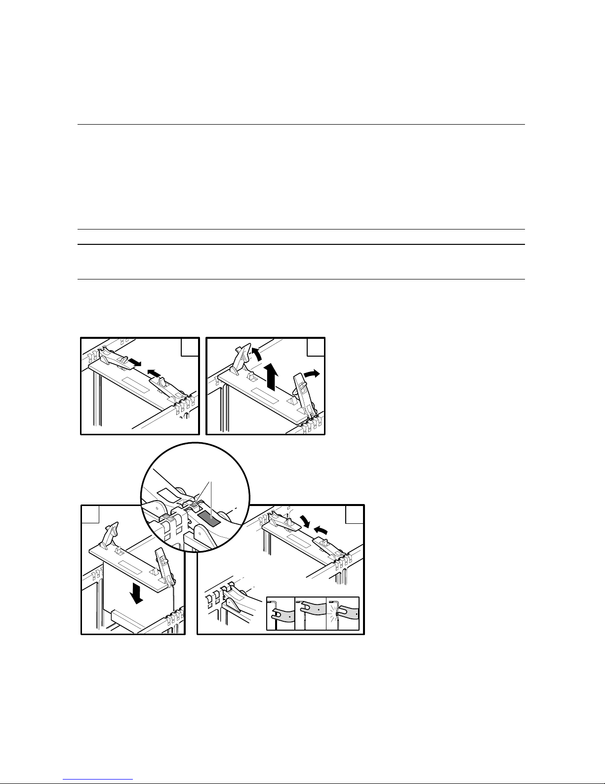
system drawer. See Chapter 2 for procedures on how to add a new
system drawer. Figure B–1 shows how to install a CPU. Table B-1
describes the different CPUs. The CPU derives its operating clock
speed from the system clock. The B4125 CPU is not supported when
the system clock is run at 9.0 ns.
NOTE: Be sure to update the firmware. See Section B.2.
Figure B–1 Installing a CPU
1
Catch Detail
PK2225
1
Removal
Replacement
2
INCORRECT
CORRECT
2
For Module
Installation, Align
Module Color to Frame
Color, as Shown
The unoccupied slot is covered with a filler. First remove the filler from the
selected slot, then proceed to install the module as follows:
Page 75

Upgrades Using B4166 and B4168 CPUs B-3
1. Check the firmware revisions and update, if necessary.
2. Ensure that the color code of the CPU module matches the color code of the slot.
3. Push the retainers on the module latches with your thumbs in the direction
of the arrows and release the latch.
4. Slide the module into the slot guide and gently push it in until the latches
are activated.
5. Close the latches onto the bulkhead and push them in until you hear one or
two clicks. The module is now firmly seated in the slot.
Table B– 1 Comparison of CPUs
CPU Part
Number
B-cache
Size
Speed
in MHz Comments
B4125 4 Mbytes 731 The B4125 must operate at this speed and requires the
system clock to run at 9.6 ns.
B4166 4 or 8
Mbytes
1001 The B4166 runs at this speed and uses all its available
B-cache when all CPUs in the system are B4166 or it
is in a system with B4168 CPUs, the clock runs at 9.0
ns, and the CPUs are in a system box with duplicate
tag support of the 8-MB cache. If the system box
duplicate tag supports only 4-MB cache, then only 4 of
the 8 Mbytes of B-cache on the CPU are used.
4 or 8
Mbytes
940 The B4166 runs at this speed and uses all its available
B-cache when all CPUs in the QBB are B4166 or it is
mixed with B4168 CPUs, but the system clock runs at
9.6 ns. If the system box duplicate tag supports only
4-MB cache, then only 4 of the 8 Mbytes of B-cache on
the CPU are used.
Uses 4 of
its 8 Mbyte
B-cache
731 The B4166 runs at this speed and uses 4 Mbytes of its
B-cache when it is in a QBB with a B4125 CPU and
the clock runs at 9.6 ns.
B4168 8 or 16
Mbytes
1224 The B4168 runs at this speed and uses all its available
B-cache when all CPUs in the system are B4168 or
B4166, the clock runs at 9.0 ns, and the CPUs are in a
system box with duplicate tag support of the 16-MB
cache. If the system box duplicate tag supports an 8MB cache, then 8 of the 16 Mbytes of B-cache on the
CPU are used.
Page 76

B-4 AlphaServer GS80 Upgrade Manual
Table B– 1 Comparison of CPUs (Continued)
CPU Part
Number
B-cache
Size
Speed
in MHz Comments
B4168 Uses 4 of
its 16 MB
B-cache
1148 The B4168 runs at this speed when placed in a QBB
that supports only 4 Mbytes of B-cache, when all
CPUs in the system are B4168 or B4166, and the
clock runs at 9.0 ns.
Uses 8 of
its 16 MB
B-cache
1001 The B4168 runs at this speed and uses 8 Mbytes of its
B-cache when the B4168 is placed in the same QBB
as the B4166 and the clock is at 9.0 ns.
4 or 8
Mbytes
940 The B4168 runs at this speed when all CPUs in the
QBB are B4168 or B4166, and the system clock runs
at 9.6 ns. If the system box duplicate tag supports
only 4-MB or 8-MB cache, then only 4 or 8 of the 16
Mbytes of B-cache on the CPU are used.
Uses 4 of
its 16 MB
B-cache
731 The B4168 runs at this speed and uses 4 Mbytes of its
B-cache when the B4168 is placed in the same QBB as
the B4125 and the clock is at 9.6 ns.
Table B– 2 Comparison of System Drawers
System Drawer
Part Number
Cache Size
Supported
by Drawer
Comments
BA52A-AA
(54-30354-03)
4 Mbytes Though the B4166 and B4168 CPUs have larger B-
caches, only 4 Mbytes are used when placed in this
backplane.
BA52A-CA
(54-30354-02)
4 or 8
Mbytes
When CPUs in this backplane are B4166 or B4168,
they use 8 Mbytes of B-cache. If a B4125 is mixed
with other speed CPUs on the same backplane, all are
configured for the 4-Mbyte B-cache size.
BA52A-DA
(54-30360-02)
4 , 8, or 16
Mbytes
When all CPUs in this backplane are B4168, they use
16 Mbytes of B-cache. If CPUs are mixed, B4125,
B4166, or B4168 on the same backplane, all are
configured for the B-cache size of the processor that
supports the smallest size (4 or 8 Mbytes).
Page 77

Upgrades Using B4166 and B4168 CPUs B-5
From outside the drawer, there is no easy way to visually distinguish between
the two system drawers; to see the components that differ requires looking
inside the drawer. The best way to determine which drawer is in the system is
to use the show fru command. The 54-class part number is listed on the
QBBx line when the show fru command is issued from either the SCM
monitor or the SRM console.
Configuration Rules
The original (blue) system upgrade is governed by the following rules:
1. Any combination of BA52A-AA, CA, and DA system drawers can be in a
system.
2. The B4125 CPUs run at 731 MHz and require a 9.6 ns system clock. B4125
CPUs are not supported with the 9.0 ns system clock.
3. B4125 CPUs have 4 Mbytes of B-cache. When in a QBB in a BA52A-CA or
DA system drawer, firmware configures these CPUs to be consistent with
the amount of B-cache available.
4. The B4166 and B4168 CPUs can operate at different speeds and use
different amounts of B-cache depending upon the drawer they are in, the
system clock speed, and whether they are configured with the B4125 CPU.
See Table B–1.
5. The B4166 CPU requires that the SRM console and microprocessor
firmware be at V6.0-514 or higher.
6. The B4168 CPU requires that the SRM console and microprocessor
firmware be at V6.3 or higher.
Page 78

B-6 AlphaServer GS80 Upgrade Manual
B.2 Upgrades Replacing Older CPUs
First, update the system firmware and then replace the old CPU(s).
See Figure B– 1. Finally, change the speed of the system clock.
Example B– 1 Updating the Firmware
P00>>> show config
Compaq Computer Corporation
Compaq AlphaServer GS80 6/731
SRM Console V5.8-1, built on May 26 2000 at 12:15:01
PALcode OpenVMS PALcode V1.81-1, Tru64 UNIX PALcode V1.75-1
Micro Firmware V5.7
QBB 0 Hard QBB 0
Quad Switch QSA rev 4, QSD revs 0/0/0/0
Duplicate Tag Up To 4 MB Caches DTag revs 1/1/1/1
.
.
.
P00>>> <esc><esc> scm
SCM_E0> set hp_count 0
SCM_E0> reset
.
.
.
P00>>> boot dqb0
.
.
.
UPD> update srm*
.
.
.
UPD> update micro
P00>>> power off
Powering off Hard_partition_0 consisting of:
QBB0
QBB1
QBB-0 Powering OFF
QBB-1 Powering OFF
Page 79

Upgrades Using B4166 and B4168 CPUs B-7
Issue the SRM show config command.
Note the version of the SRM console. The B4166 requires V6.0-514 or
higher, and the B4168 requires V6.3 or higher.
Note the firmware revision of the microprocessors. The B4166 requires
V6.0-514 or higher, and the B4168 requires V6.3 or higher.
Issue the <esc><esc>SCM command to get to the SCM monitor. Only
necessary if the system is partitioned.
Issue the set hp_count 0 command if the system is partitioned.
Issue the reset command to get back to the SRM console to run LFU.
Boot LFU. In this case, LFU is booted off the CD-ROM in a master PCI
box.
Issue the LFU update srm* command.
Issue the LFU update micro command. The system power-cycles
automatically after the micros are updated. The environment variables
determine the prompt that the system returns to.
Issue the SRM power off command.
Once the system firmware is updated and the system is powered off, place the
main circuit breaker in the Off position and replace the old CPUs.
Page 80
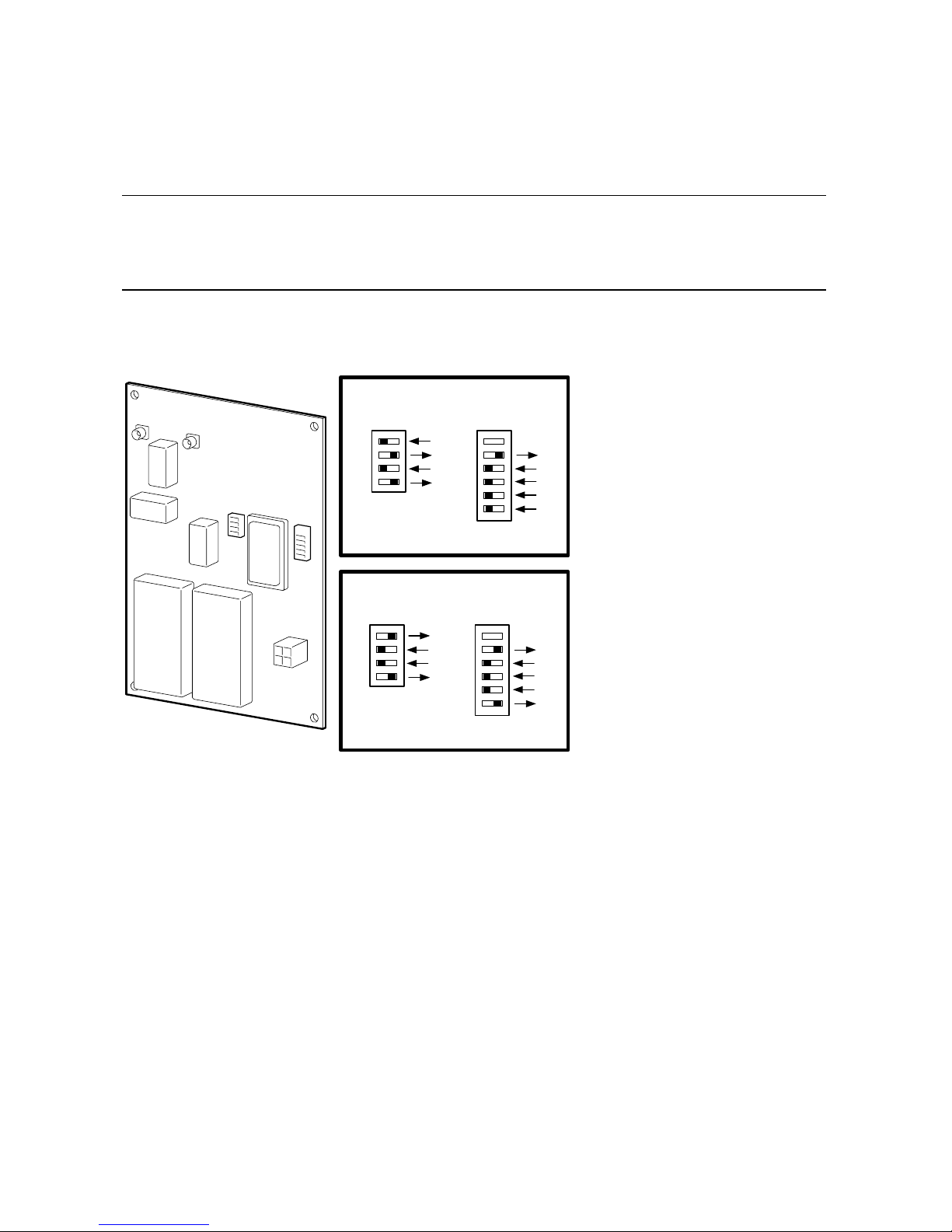
B-8 AlphaServer GS80 Upgrade Manual
B.3 Changing the Clock Module Switch Settings
Two switch packs on the clock module control the clock frequency. If
no B4125 CPUs are in the system, the clock can run at the faster speed
(9.0 ns).
Figure B– 2 System Clock Switch Packs
1
2
3
4
5
6
1
1
2
3
4
55.6 MHz/9.0 ns
PK3247
0
S2
S2
S1
01
S1
1
2
3
4
5
6
1
1
2
3
4
52.2 MHz/9.6 ns
0
S2
01
S1
Page 81
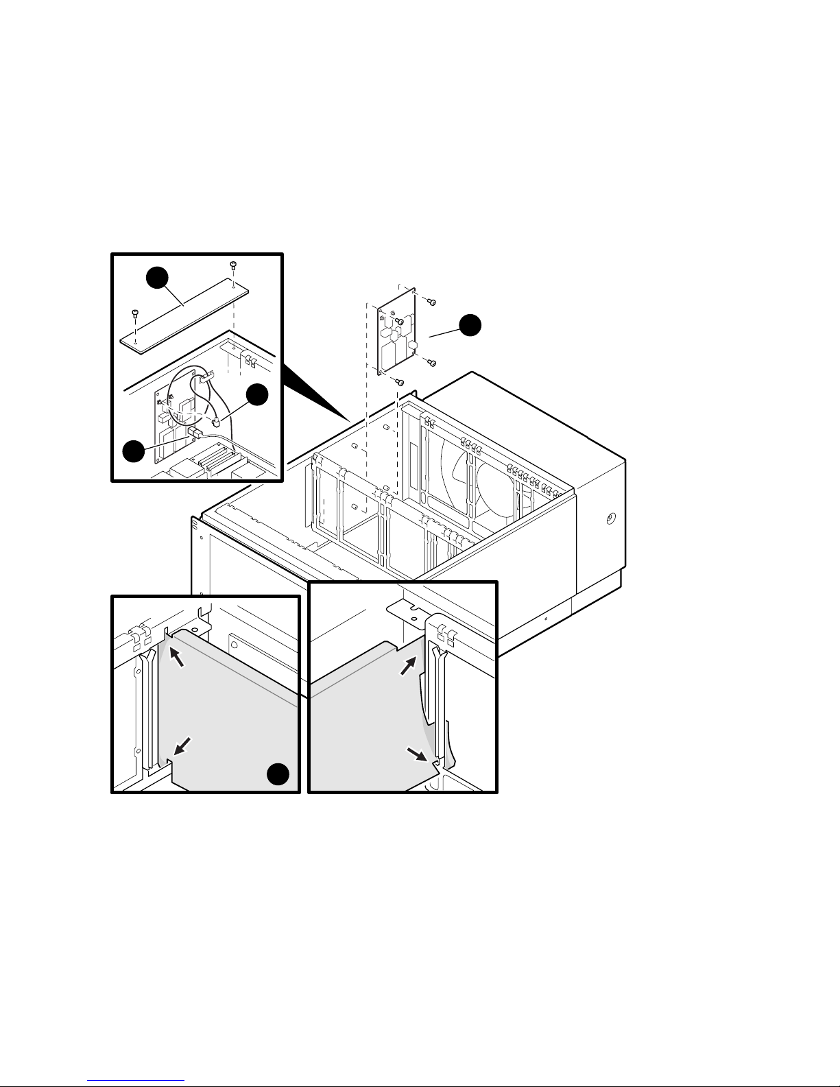
Upgrades Using B4166 and B4168 CPUs B-9
The switch packs on the master clock control the speed of the system. When
B4125 CPUs are in the system, the clock runs at 9.6 ns. To set the system
speed to 9.0 ns, access the clock module and change the switches.
Figure B– 3 Accessing the Clock Module
PK1249
1
4
3
5
(Right Side)
(Left Side)
2
Page 82

B-10 AlphaServer GS80 Upgrade Manual
1. Access the top system drawer and remove CPU3 and memory 2 to allow
space to access the clock module.
2. Remove the clock module cover plate in the rear left corner of the drawer
compartment by removing the two Phillips head screws holding it in place
and lift it out of the drawer.
3. Remove the clock compartment shield. Note how the shield is installed.
4. Unplug the coax clock cable(s) from the clock module.
5. Unplug the power cable.
6. Unscrew the four Phillips head screws holding the module to the side of the
drawer and remove the module.
7. Check the bit settings on the two switches. See Figure B-2 for switch
orientation and bit settings.
Page 83
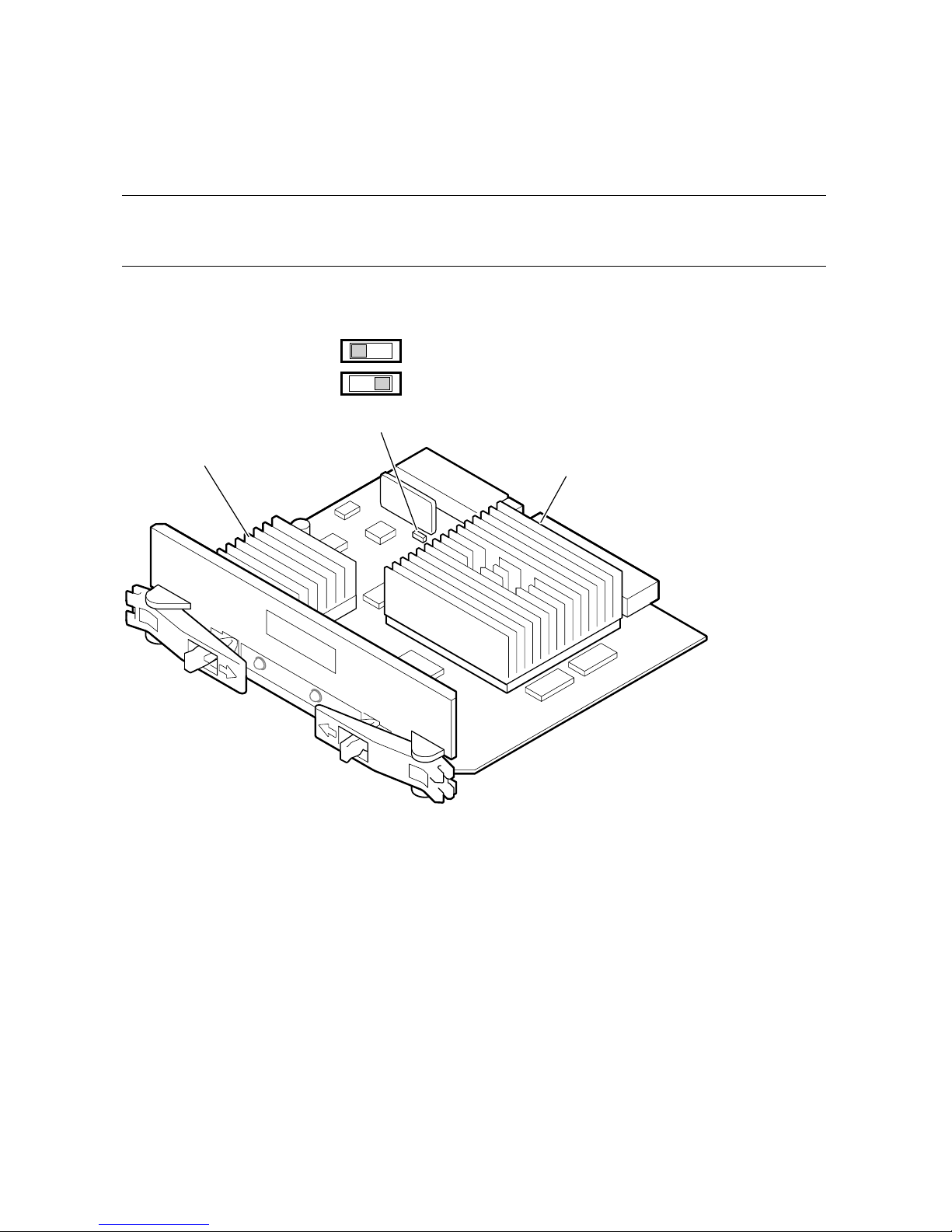
Upgrades Using B4166 and B4168 CPUs B-11
B.4 B4168 Compatibility Switch
The B4168 CPU module has a switch that must be set if the module is
to be used with B4125 modules in the same QBB.
Figure B– 4 Setting the B4168 Switch
CPU Chip
Power
Converter
MR0489
S1 Switch
For use with B4168 or B4166 CPUs
For use with B4125 CPUs
Figure B–4 shows the location of the S1 switch that must be changed if the
module is to be in a QBB with a B4125 module.
As viewed here, the switch would be set to the left for 1224/1001 MHz speeds;
this is the default position. When set to the right, the switch allows the module
to operate with a B4125 module running at 731 MHz.
Page 84

B-12 AlphaServer GS80 Upgrade Manual
B.5 Verification
When you power up the system, check that the SCM correctly maps the QBBs
in the system. Execute the SRM set sys_serial_num command.
Run Q-Vet (see Section 4.4.2).
Page 85
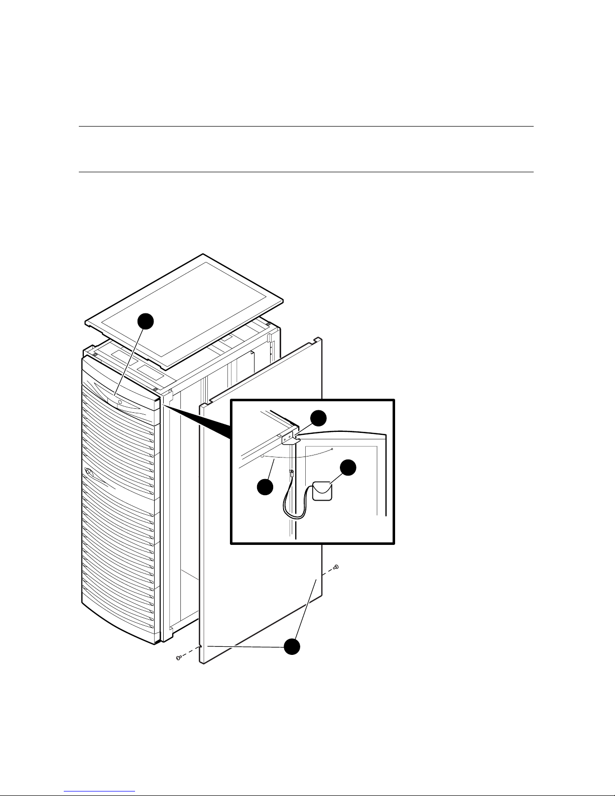
Upgrades Using B4166 and B4168 CPUs B-13
B.6 Replacing the System Cosmetics
After a system is completely upgraded, new cabinet doors, sides, and
top may be installed.
Figure B– 5 GS80 Cabinet
3
5
PK3249
1
2
4
Page 86

B-14 AlphaServer GS80 Upgrade Manual
Door Removal
1. Open the front door and remove the screw at the cabinet end of the ground strap.
2. If the door has a service pouch on it, remove it and place it inside the cabinet.
3. Disconnect all cables to the OCP.
4. Remove the outer screw of the upper bracket holding the door to the frame.
5. Loosen the inner screw of the upper bracket and slide the door and bracket to let
the screw pass through the bracket.
6. Tilt the door away from the cabinet and lift it off the bottom bracket.
7. Remove the bottom bracket.
Top Cover Removal
1. The top cover is held in place by plastic tabs at the front and back of the cover.
Push the cover up to release the tabs and lift it off the cabinet.
Top Cover Replacement
1. Replace the cover after you have replaced the side panels. Covers are different for
each cabinet. Place the correct cover on the correct cabinet and snap in place.
Side Panel Removal
1. The side panels are held in place by two screws toward the bottom of the panel at
the front and at the rear of the cabinet. Loosen both screws.
2. Pull the bottom of the panel free from the side members of the frame and lift it off
the top frame member.
Side Panel Replacement
1.
Reverse the removal procedure.
Door Replacement
1.
Replace the doors after you have replaced the side panels and covers.
2.
Reverse the removal procedure.
Page 87

Index-1
Index
B
Block diagram, 1-3
C
Cabinet preparation, 3-6
Cabinets, 1-5
Clock connections, 2-8
Configurations, expander cabinet, 3-10
Connections
clock, 2-8
CSB, 2-14
global port, 2-8
ground, 2-8
PCI box, 3-8
power, 2-14
signal, 2-14
Control panel keyswitch, 4-1, 4-2
CPU switch, 1-11
CPU upgrades, 1-3
CSB connections, 2-14
D
De-installing Q-VET, 4-22
Distribution board assembly, 2-6
E
Expander cabinet configurations, 3-10
G
Global port connections, 2-8
Ground connections, 2-8
GS80 block diagram, 1-3
GS80 physical diagram, 1-4
GS80 system, 1-2
I
Installation
distribution board assembly, 2-6
PCI box, 3-2
power subrack, 2-2
second drawer, 2-4
Installing Q-VET, 4-16
K
Keyswitch, 4-1, 4-2
Keyswitch functions, 4-3
M
Mounting hardware, PCI box, 3-3
Mounting locations
Memory Channel, 3-15
PCI box, 3-14
Starlight, 3-12
StorageWorks, 3-13
P
PCI box
cable connections, 3-8
installation, 3-2
mounting hardware, 3-3
preparation, 3-4
Physical diagram, 1-4
Power connections, 2-14
Power requirements, 1-5
Power subrack installation, 2-2
Power-up, 4-5
Power-up display, 4-5
Page 88

Index-2
Q
QBB, 1-2
Q-VET installation verification, 4-14
Q-VET results review, 4-20
R
Running Q-VET, 4-18
S
Second drawer installation, 2-4
Signal connections, 2-14
SMC, 4-4
System management console, 4-4
System upgrades, 1-3
U
Upgrades
CPU, 1-3, B-1
system, 1-3
 Loading...