

Page 1

HP A6616 Router
Installation Manual
Page 2

About This Manual
Organization
HP A6616 Routers Installation Manual is organized as follows:
Chapter Contents
1 Router Overview
Briefly introduces the product specifications, as well as
the features and applications of the HP A6616.
2 Preparing for Installation
Describes the requirements on installation site, the
safety recommendations before and during installation,
and the required tools.
3 Installing the Router
Introduces how to install the A6616, as well as how to
connect the power cable, console cable, AUX port
cable, Ethernet cable, interface card and interface
module cable.
4 Starting and Configuring the Router
Helps you get familiar with the basic knowledge of how
to boot and configure the HP A6616, including device
startup, power-on, and initialization of system files, and
so on.
5 Maintaining Software
Introduces how to maintain the software of the HP
A6616, including upgrading the software and updating
the configuration files.
6 Maintaining Hardware
Introduces how to maintain the hardware of the HP
A6616.
7 Troubleshooting
Describes some problems that may occur during
installation and startup of the router and how to solve
them.
Conventions
The manual uses the following conventions:
Command conventions
Convention Description
Boldface The keywords of a command line are in Boldface.
italic Command arguments are in italic.
[ ] Items (keywords or arguments) in square brackets [ ] are optional.
{ x | y | ... }
Alternative items are grouped in braces and separated by vertical bars. One is
selected.
[ x | y | ... ]
Optional alternative items are grouped in square brackets and separated by
vertical bars. One or none is selected.
Page 3

Convention Description
{ x | y | ... } *
Alternative items are grouped in braces and separated by vertical bars. A
minimum of one or a maximum of all can be selected.
[ x | y | ... ] *
Optional alternative items are grouped in square brackets and separated by
vertical bars. Many or none can be selected.
&<1-n> The argument(s) before the ampersand (&) sign can be entered 1 to n times.
# A line starting with the # sign is comments.
GUI conventions
Convention Description
Boldface
Window names, button names, field names, and menu items are in Boldface.
For example, the New User window appears; click OK.
>
Multi-level menus are separated by angle brackets. For example, File >
Create > Folder.
Convention Description
< > Button names are inside angle brackets. For example, click <OK>.
[ ]
Window names, menu items, data table and field names are inside square
brackets. For example, pop up the [New User] window.
/
Multi-level menus are separated by forward slashes. For example,
[File/Create/Folder].
Symbols
Convention Description
Means reader be extremely careful. Improper operation may cause bodily
injury.
Means reader be careful. Improper operation may cause data loss or damage
to equipment.
Means an action or information that needs special attention to ensure
successful configuration or good performance.
Means a complementary description.
Means techniques helpful for you to make configuration with ease.
Related Documentation
In addition to this manual, each HP A6600 Routers documentation set includes the following:
Manual Description
HP A6600 Routers User Manual
It is a guide for the user to perform the operations
correctly. It is organized into the parts of access, IP
services, IP routing, MPLS, VPN, QoS, security,
Page 4

Manual Description
system, multicast, and OAA.
It also gives the user a detailed description of the
operating commands. It is organized into the parts of
access, IP services, IP routing, MPLS, VPN, QoS,
security, system, multicast, and OAA, as well as a
command index.
HP A6600 Routers Interface Card and Interface
Module Manual
This manual introduces all kinds of interface modules
that SR6600 routers support, the means of
connection the interface cables and the interface
module purchase guide.
Low-End and Mid-Range Series Routers Cable
Manual
This manual introduces all cable pinouts available
with low-end and mid-range series routers.
Environmental Protection
This product has been designed to comply with the requirements on environmental
protection. For the proper storage, use and disposal of this product, national laws and
regulations must be observed.
Page 5

1 Router Overview
Introduction
The HP A6616 router (hereinafter referred to as the A6616) is a high-performance service
router developed by Hewlett Packard (hereinafter referred to as HP), serving as the core router
on a carrier network or large enterprise network.
The A6616 adopts two main processing units (MPUs), redundant power modules, and a
distributed modular architecture. Abundant optional modules are available so that the two
service routers can have a powerful processing capability and support flexible configuration to
fully meet the requirements of the carrier network and enterprise network. The A6616 can work
at the core layer of small- and medium-sized MANs or provincial networks.
With the high-performance microprocessor technology, advanced hardware architecture and HP
proprietary Comware V5 platform, the A6616 provides high service processing capacity, flexible
service scalability, and high reliability. The A6616 can work together with other HP network
routers to provide comprehensive network solutions for medium- and large-sized enterprises,
carriers, and users in the fields of electric power, finance, taxation, public security, railway and
education. The full compliance with national and international standards ensures interoperability
with products of other manufacturers at different layers.
The A6616 supports high-speed interface modules (HIMs) and provide a bus processing
capability up to 10 Gbps, which can meet the high-speed performance requirements of users. In
addition, the A6616 is compatible with some multi-functional interface modules (MIMs) of the HP
MSR/AR series routers to guarantee the smooth upgrade from narrowband access to
broadband access, improve the competitiveness, and protect existing investments.
You can configure MPUs and flexible interface platforms (FIPs) on the A6616 as needed. Table
1-1 describes MPUs' support for FIPs on the A6616.
Table 1-1 MPUs' support for FIPs
MPU FIP-100 FIP-110 FIP-200 FIP-210
RPE-X1 Supported Supported Supported Supported
RSE-X1 Not supported Supported Not supported Supported
The A6616 supports two types of MPUs, route processing engine (RPE) and route switch
engine (RSE).
To facilitate description, the term "FIP" is used throughout this document to refer to the FIP-
100, FIP-110, FIP-200, and FIP-210 if not otherwise specified.
The FIP-100 and FIP-110 support MIMs only.
The FIP-200 and FIP-210 support MIMs, HIMs, and HIM/MIM intermixing.
For details about the slot arrangement, refer to Chapter 2 "Arranging Slots and Numbering
Interfaces."
For details about installation and removal of HIMs and MIMs, refer to Chapter 4 "Installing the
Router.”
Page 6

Physical Description
Front View
Figure 1-1 Front view of the A6616 (configured with an RPE-X1)
(1) Mounting bracket (2) Fan tray
(3) Weight-bearing warning label (100 kg/220.46 lb) (4) Chassis handle
(5) Cable management bracket (6) FIP slot (Slot 9)
(7) FIP slot (Slot 8) (8) FIP-200 (Slot 7)
(9) FIP slot (Slot 6) (10) Air inlets (air filters are optional)
(11) Power module slot (PWR3) (12) AC power module (PWR1)
(13) Power module slot (PWR2) (14) Power module slot (PWR4)
(15) ESD socket and silkscreen (16) MPU slot (Slot 4)
(17) RPE-X1 (Slot 5) (18) FIP slot (Slot 3)
(19) FIP slot (Slot 2) (20) FIP slot (Slot 1)
(21) FIP slot (Slot 0)
Page 7
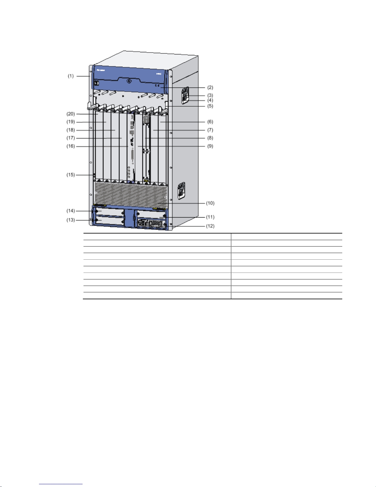
Figure 1-2 Front view of the A6616 (configured with an RSE-X1)
(1) Mounting bracket (2) Fan tray
(3) Weight-bearing warning label (100 kg/220.46 lb) (4) Chassis handle
(5) Cable management bracket (6) FIP slot (Slot 9)
(7) FIP slot (Slot 8) (8) FIP-210 (Slot 7)
(9) FIP slot (Slot 6) (RSE-X1 compatible) (10) Air inlets (air filters are optional)
(11) Power module slot (PWR3) (12) AC power module (PWR1)
(13) Power module slot (PWR2) (14) Power module slot (PWR4)
(15) ESD socket and silkscreen (16) RSE-X1 (Slot 5)
(17) FIP slot (Slot 3) (18) FIP slot (Slot 2)
(19) FIP slot (Slot 1) (20) FIP slot (Slot 0)
Page 8
Rear View
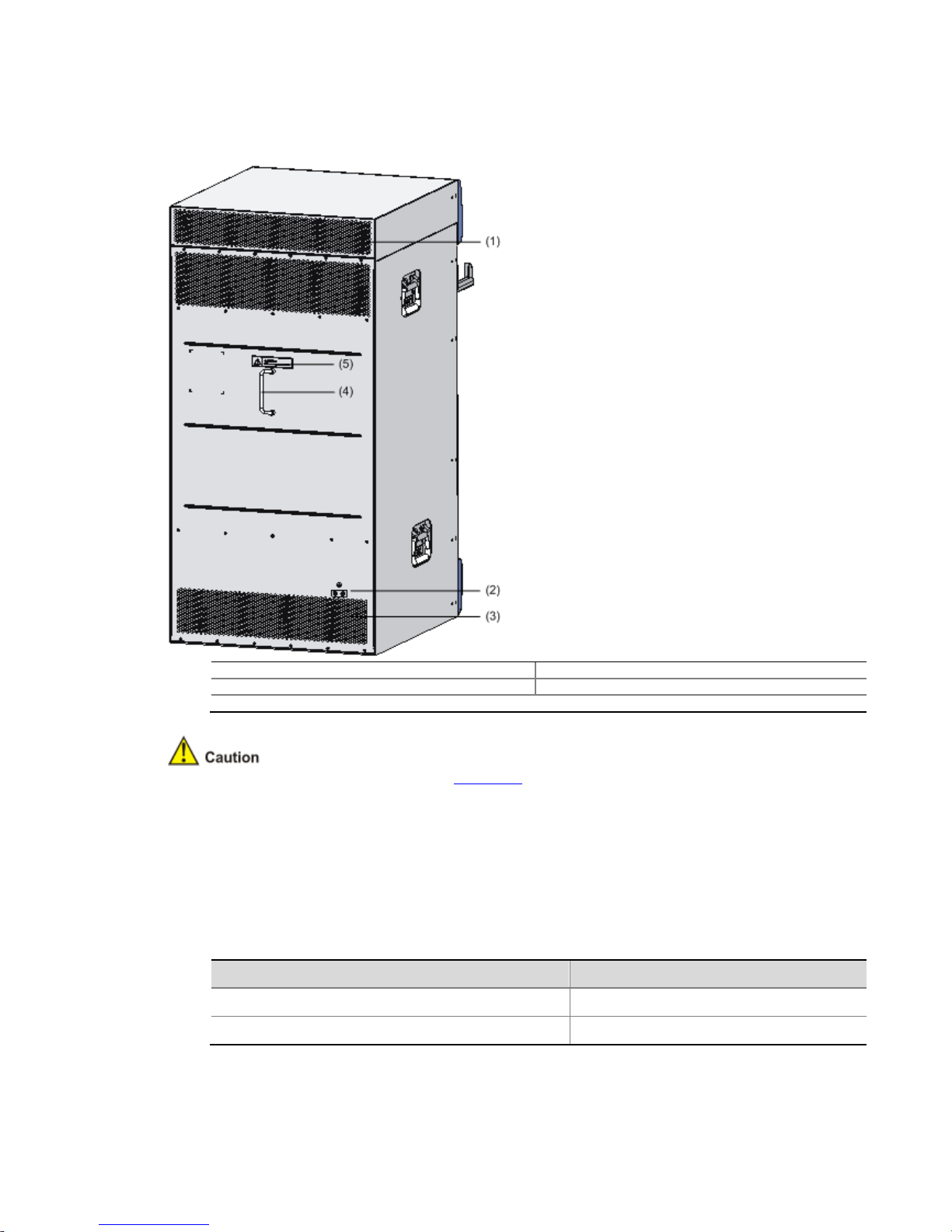
Figure 1-3 Rear view of the A6616
(1) Air exhaust vents for the chassis (2) Grounding screw and sign
(3) Air exhaust vents for power modules (4) Handle on the rear chassis panel
(5) Warning label
Do not hold the handle indicated by (4) in Figure 1-3 on the rear chassis panel to move the
chassis because it is designed for the convenience of the rear chassis panel removal, but not
for bearing the chassis weight.
System Specifications
Dimensions and Weight
Table 1-2 Dimensions and weight
Item Specification
Dimensions without feet and mounting ears (H × W × D) 886 × 436 × 480 mm (34.9 × 17.2 × 18.9 in.)
Weight (fully configured) < 100 kg (220.5 lb.)
Page 9

Power Modules
Table 1-3 Power module specifications
Item Specification
Rated voltage range
AC powered: 100 VAC to 240 VAC; 50 Hz or 60 Hz
DC powered: –48 VDC to –60 VDC
Maximum input current
AC powered: 10 A
DC powered: 25 A
Maximum power provided by one power
module
650 W
Physical dimensions (H × W × D) 40 × 140 × 354 mm (1.57 × 5.51 ×13.94 in.)
Power module slots
Four power module slots are offered. The power modules must
have the same specifications.
Intelligent power supply management is supported.
Power module redundancy backup is recommended for high
reliability.
Power consumption range 97.5 W to 1166.5 W
Figure 1-4 AC power module
(1) Captive screw (2) Bail latch
(3) Power socket (4) Power switch
(5) Power LED (6) Power module handle
Page 10

Figure 1-5 DC power module
(1) Captive screw (2) Power input terminals
(3) Power switch (4) Power LED
(5) Power module handle
Table 1-4 Description of AC and DC power LEDs
Status Meaning
Solid green The power module is working normally.
Solid red The power module is faulty.
Intelligent Power Supply Management
The A6616 supports either AC or DC power supply. Power modules of different types cannot
operate on the same A6616.
The A6616 provides four power module slots. You are recommended to configure power
redundancy backup to ensure high reliability.
The A6616 supports FIP power-on priorities management, power redundancy management,
and power management. These functions effectively prevent service anomalies caused by
power failure.
The A6616 supports online insertion but not online removal of a power module.
Online refers to first switching off the power module and then removing it from the router or
inserting it into the router. Before doing that, make sure that the router is configured with
redundant power modules and the system services are running normally.
FIP power-on priorities management
The A6616 provides eight FIP slots, including Slot 0 through Slot 3, and Slot 6 through Slot 9.
You can configure FIPs with different power-on priorities, namely, Level 1 through Level 3.
Level 1 is the highest power-on priority, while Level 3 is the lowest.
The default power-on priority of an inserted FIP is Level 2. Use the power-supply policy
priority priority level slot slot number command to set the power-on priority of an inserted FIP.
Power redundancy management
To avoid service interruption caused by power module failure during the operation of a device,
you are recommended to configure power redundancy for the device. The redundant power
modules can automatically implement backup without further configurations.
Use the display power-supply command to view the system power information, so that you
can take countermeasures in time.
Page 11

Take 650 W power modules for example. If a device requires an actual operation power of 1000
W, you need to install two 650 W power modules to ensure normal working of the device.
Optionally, you can install altogether three such power modules with one of them for power
redundancy or four such power modules with two of them for power redundancy.
Power management
The A6616 supports power management. This function prevents a single faulty power module
from affecting the whole router, and hence ensures the normal operation of services.
To be more specific, after the MPU starts up, the online FIPs are powered on in descending
order of their priorities. FIPs with the same priority are powered on in ascending order of their
slot numbers. This process goes on until the system power is insufficient or all the FIPs are
powered on.
For example, on an A6616, suppose that the system power is sufficient. If FIP-200s are inserted
into Slot 1, Slot 3, Slot 7, and Slot 9 with power-on priorities Level 2, Level 3, Level 2, and Level
1 respectively, the FIP-200s are powered on in the order of Slot 9, Slot 1, Slot 7, and Slot 3.
Use the display power-supply command or the display power-supply verbose command to
view the power management information. You can manually power on or power off the FIPs as
needed, in order to adjust the available system power. Use the undo remove slot slot-number
command to power on the FIP in the specified slot. Use the remove slot slot-number command
to power off the FIP forcibly.
Do not power off a running power module. Otherwise, the power supply may be insufficient, and
a system power failure or FIP power failure may occur.
For details about commands in intelligent power supply management, refer to Device
Management in the System Volume of HP SR6600 Routers User Manual.
Fan Tray
Table 1-5 Fan tray specifications
Fan tray Specification
Number of fans 9 (supporting automatic fan speed adjustment)
Fay tray dimensions (H × W × D) 78.1 × 410.2 × 447.8 mm (3.07 × 16.15 × 17.63 in.)
Weight 5 kg (11.02 lb)
Failsafe Supported
Hot swappable Supported
Table 1-6 Description of fan tray LEDs
LED Status Meaning
RUN (green)
Off The system is powered off or the fan tray is faulty.
On The fan tray is working normally.
ALM (red)
Off The fan tray is working normally.
On The fan tray is faulty.
Page 12

Operating environment
Table 1-7 Operating environment specifications
Item Specification
Operating temperature 0°C to 45°C (32°F to 113°F)
Operating humidity 10% to 95%, noncondensing
Altitude –60 m to +4 km (–196.85 ft. to +2.49 miles)
System Software
The router uses the Comware V5 software platform, HP's core software platform.
Based on the IPv4/IPv6 dual stack, the Comware V5 software platform integrates link-layer
protocols, routing, Multi-Protocol Label Switching (MPLS), Virtual Private Network (VPN), quality
of service (QoS), security, and multicast technologies. It is scalable and portable because it
adopts a modular architecture and effectively encapsulates and masks different operating
systems and hardware. The Comware V5 software platform is the basis of all series of IP
network products of HP.
MPU
RPE-X1
Front view
Figure 1-6 Front view of the RPE-X1
(1) Captive screw (2) Ejector lever
(3) RESET button (RESET) (4) Run LED (RUN)
(5) Active LED of the RPE-X1 (ACT) (6) Alarm LED (ALM)
(7) Link state/data reception & transmission LED (LINK/ACT)
(8) Management Ethernet interface (MANAGEMENT) (10/100/1000BASE-T)
(9) Console port (CONSOLE) (10) CF card eject button
(11) AUX port (AUX) (12) CF card slot
(13) USB interface 0 (0) (host mode) (14) USB interface 1 (1) (device mode)
(15) CF LED (CF) (16) USB interface 1 LED (USB)
Technical specifications
Table 1-8 Technical specifications for the RPE-X1
Item Specification
Processor Power PC 1GHz
Processor cores 1
Flash 4 MB
Page 13

Item Specification
Memory type and size
DDR2 SDRAM
1 GB (default, one memory module)
2 GB (maximum)
NVRAM 128 KB
Console port 1 (9600 bps to 115200 bps, 9600 bps by default)
AUX port 1 (9600 bps to 115200 bps, 9600 bps by default)
Management Ethernet interface 1 (10Base-T/100Base-TX/1000Base-T)
CF card
256 MB by default for the built-in CF card
256 MB, 512 MB, or 1 GB for an optional external CF card (CF
cards less than 256 MB are not supported)
USB interfaces
2 (USB 0: Type A connector, operating in the host mode; USB 1:
Type B connector, operating in the device mode)
Reset Button 1
Dimensions (H × W × D) 40 × 199 × 282 mm (1.57 × 7.83 × 11.10 in.)
Power consumption 37 W
Hot swapping Supported
Flash is used for storing the boot file—the BootWare program.
The memory is used for storing the data during system operation and caching the data during
data forwarding.
The non-volatile random access memory (NVRAM) is used for storing the exception information
of the system during operation.
A CF card is used for storing the programs and configuration files of the device.
Hot-swapping a module refers to first using the remove slot slot-number command to stop the
module, and then manually pulling it out, or inserting the module into its slot without powering
off the device. For details about the remove slot command, refer to Device Management in the
System Volume of HP SR6600 Routers User Manual.
LEDs
Figure 1-7 LEDs on the RPE-X1
(1) Run LED (RUN) (2) Active LED (ACT) (3) Alarm LED (ALM)
(4) Ethernet link state/data reception & transmission LED (LINK/ACT)
(5) CF LED (CF) (6) USB interface 1 LED (USB)
Table 1-9 Description of the LEDs
LED Status Meaning
Device LEDs RUN (green) Off No power input is available, or the RPE-X1 is faulty.
Page 14

LED Status Meaning
Slow blinking
(1 Hz)
The RPE-X1 is operating normally.
Fast blinking
(8 Hz)
The application software is being loaded (in this case,
never power off the device or hot-swap the RPE-X1;
otherwise the RPE-X1 may be damaged).
ACT (green)
Off The RPE-X1 is in the standby state.
On The RPE-X1 is in the active state.
ALM (red)
Off The system is operating normally and there is no alarm.
On
A fault has occurred to the system or the power is
insufficient. In this state, you need to check the system
log immediately.
Fast blinking
(8 Hz)
A critical fault has occurred to the system. In this state,
you need to handle the fault immediately.
Management
Ethernet
interface LED
LINK/ACT
(yellow/green)
Solid yellow A 10/100 Mbps link is present.
Solid green A 1000 Mbps link is present.
Blinking
yellow
Data is being received or transmitted at a rate of 10/100
Mbps.
Blinking
green
Data is being received or transmitted at a rate of 1000
Mbps.
USB LED USB (green)
Off No host is connected to the device-mode USB interface.
On
A host is connected to the device-mode USB interface.
The USB cable can be unplugged in this state.
Blinking
Data is being transmitted or received through the devicemode USB interface. In this state, do not unplug the USB
cable.
CF LED CF (green)
Off No CF card is present or the CF card is not recognizable.
On A CF card is in position and has passed the POST.
Blinking
The system is accessing the CF card. In this state, do not
remove the CF card.
Do not remove the CF card when the CF LED is blinking. Otherwise, the file system on the CF
card will be damaged.
Page 15

RSE-X1
Front view
Figure 1-8 Front view of RSE-X1
(1) Captive screw (2) Ejector lever
(3) SMB coaxial clock interface (reserved) (4) RESET button (RESET)
(5) CF card eject button (6) CF card slot
(7) CF LED (CF) (8) USB interface 0 (0) (host mode)
(9) USB interface 1 (1) (device mode) (10) USB interface 1 LED (USB)
(11) Link state/data reception & transmission LED (LINK/ACT)
(12) Management Ethernet interface (MANAGEMENT) (10/100/1000BASE-T)
(13) Console port (CONSOLE) (14) AUX port (AUX)
(15) Active LED of the RSE-X1 (ACT) (16) Power management alarm LED (PALM)
(17) Run LED (RUN) (18) Alarm LED (ALM)
Technical specifications
Table 1-10 Technical specifications for the RSE-X1
Item Specification
Processor MIPS 1GHz
Number of processor cores 2
Flash 4 MB
Memory type and size
DDR2 SDRAM
2 GB (default, two memory modules)
2 GB (maximum)
NVRAM 128 KB
Console port 1 (9600 bps to 115200 bps, 9600 bps by default)
AUX port 1 (9600 bps to 115200 bps, 9600 bps by default)
Management Ethernet interface 1 (10Base-T/100Base-TX/1000Base-T)
CF card
256 MB by default for the built-in CF card
256 MB, 512 MB, or 1 GB for an optional external CF card (CF
cards less than 256 MB are not supported)
USB interfaces
2 (USB 0: Type A connector, operating in the host mode; USB 1:
Type B connector, operating in the device mode)
Reset button 1
Dimensions (H × W × D) 45 × 399 × 412 mm (1.77 × 15.71 × 16.22 in.)
Power consumption 75 W
Hot swapping Supported
Page 16

"Hot-swapping" a module refers to first using the remove slot slot-number command to stop the
module, and then manually pulling it out, or inserting the module into its slot without powering
off the device. For details about the remove slot command, refer to Device Management in the
System Volume of HP SR6600 Routers User Manual.
LEDs
Figure 1-9 LEDs on the RSE-X1
(1) CF LED (CF) (2) USB interface 1 LED (USB)
(3) Ethernet link state/data reception & transmission LED (LINK/ACT)
(4) Active LED of the RSE-X1 (ACT) (5) Power management alarm LED (PALM)
(6) Run LED (RUN) (7) Alarm LED (ALM)
Table 1-11 Description of the LEDs of the RSE-X1
LED Status Meaning
Device LEDs
RUN (green)
Off No power input is available, or the RSE-X1 is faulty.
Slow
blinking (1
Hz)
The RSE-X1 is operating normally.
Fast
blinking (8
Hz)
The application software is being loaded (in this case,
never power off the device or hot-swap the RSE-X1;
otherwise the RSE-X1 may be damaged).
ACT (green)
Off The RSE-X1 is in the standby state.
On The RSE-X1 is in the active state.
ALM (red)
Off The system is operating normally and there is no alarm.
On
A fault has occurred to the system. In this state, you need
to check the system log immediately.
Fast
blinking (8
Hz)
A critical fault has occurred to the system. In this state,
you need to handle the fault immediately.
PALM (red)
Off The system power supply is normal.
On The system power is insufficient.
Management
Ethernet
interface LED
LINK/ACT
(yellow/green)
Solid
yellow
A 10/100 Mbps link is present.
Solid green A 1000 Mbps link is present.
Blinking
yellow
Data is being received or transmitted at a rate of 10/100
Mbps.
Blinking
green
Data is being received or transmitted at a rate of 1000
Mbps.
USB LED USB (green) Off No host is connected to the device-mode USB interface.
Page 17

LED Status Meaning
On
A host is connected to the device-mode USB interface.
The USB cable can be unplugged in this state.
Blinking
Data is being transmitted or received through the devicemode USB interface. In this state, do not unplug the USB
cable.
CF LED CF (green)
Off No CF card is present or the CF card is not recognizable.
On A CF card is in position and has passed the POST.
Blinking
The system is accessing the CF card. In this state, do not
remove the CF card.
Do not remove the CF card when the CF LED is blinking. Otherwise, the file system on the CF
card will be damaged.
Components
An MPU is the control center of the device. It is responsible for:
Computing device routes and maintaining forwarding tables
Configuring and monitoring FIPs; updating and resetting FIPs or interface modules
Providing high-precision clock for the system and the real-time clock (RTC) function
Processor
The RPE-X1 uses the Power PC 1GHz processor as the routing processing engine.
The RSE-X1 uses the MIPS 1GHz processor as the routing processing engine.
Flash
The Flash size is 4 MB, of which 1 MB is used for storing the boot file—BootWare and the
remaining space for BootWare backup and important system parameters.
Memory
A memory module is used for storing the data exchanged between the system and the CPU.
The default memory size of the RPE-X1 is 1 GB (one 1 GB memory module) and the maximum
memory size is 2 GB. An RPE-X1 provides two memory slots in which you can insert two DDR2
SDRAMs of different sizes.
The DDR2 SDRAMs for the RPE-X1 have two sizes:
DDR2 SDRAM-512MB
DDR2 SDRAM-1GB
The default memory size of the RSE-X1 is 2 GB (two 1 GB memory modules) and the maximum
memory size is 2 GB. An RSE-X1 provides two memory slots in which you can insert two DDR2
SDRAM-1GB modules.
NVRAM
The NVRAM is 128 KB in size and is used for storing exception information of the system during
operation.
CF card
1) Introduction
A compact flash (CF) card is used for storing logs, host files, and configuration files.
The device is equipped with a built-in 256 MB CF card, which is identified with cfa0. In addition,
the device provides an external CF card slot to expand the local storage space. A CF card
inserted into the external CF card slot is identified with cfb0.
The CF cards supported by the device are available in three sizes:
256 MB
Page 18

512 MB
1 GB
Use CF cards provided by HP only. The device may be incompatible with other CF cards.
CF cards less than 256 MB are not supported.
2) CF card and slot
Figure 1-10 CF card and slot
(1) Eject button (CF card) (2) CF card slot (3) CF LED (CF)
3) CF LED
For the description of the CF LED, see Table 1-9 and Table 1-11.
The CF card is hot-swappable. When the CF LED is blinking, do not unplug the CF card.
Otherwise, the file system on the CF card will be damaged.
Console port
1) Introduction
The router provides an RS-232 asynchronous serial console port that can be connected to a
computer for system debugging, configuration, maintenance, management, and host software
loading.
2) Technical specifications for the console port
Table 1-12 Technical specifications for the console port
Item Specification
Connector RJ-45
Compliant standard Asynchronous EIA/TIA-232
Baud rate
9600 bps to 115200 bps
9600 bps (default)
Transmission Distance ≤ 15 m (49.21 ft.)
Services
Connection to an ASCII terminal
Connection to the serial interface of a local PC to run the terminal
emulation program
Command line interface (CLI)
3) Console cable
The console cable is an 8-core shielded cable. The RJ-45 connector at one end of the cable is
for the console port on the router, and the DB-9 female connector at the other end is for the
serial port on a configuration terminal.
Figure 1-11 illustrates the console cable.
Page 19

Figure 1-11 Console cable
Table 1-13
Console cable connector pinouts
RJ-45 pin
1
2
3
4
5
6
7
8
For the connection of the console cable, refer to “Connecting the Console Cable” in Chapter 4
“Installing the Router”
AUX port
1) Introduction
The AUX port is an RS-
232 asynchronous serial interface used for remote configuration or
dialup backup. You need to connect the local modem to the remote modem through PSTN and
then to the remote device for remote system deb
management. In the event that the console port fails, the AUX port can be connected to a
terminal as a backup port of the console port. For details, refer to “Using the Port AUX as
Backup Console Port” in Chapter 7 “
2)
Technical specifications for the AUX port
Table 1-14
Technical specifications for the AUX port
Item
Connector
Compliant standard
Baud rate
Services
3) AUX cable
The AUX cable is an 8-
core shielded cable. At one end of the cable is an RJ
which is connected to the AUX port on the router. At the other end are a DB
Signal direction DB-9 pin
8
6
2
1
— 5
3
4
7
ugging, configuration, maintenance, and
Troubleshooting.”
Specification
RJ-45
Asynchronous EIA/TIA-232
9600 bps to 115200 bps
9600 bps (default)
Used to connect the serial interface of a remote PC through a pair of
modems to establish a dial-
up connection with the PC
-
9 (male) connector
Signal
CTS
DSR
RXD
DCD
GND
TXD
DTR
RTS
-45 connector,
Page 20

and a DB-
25 (male) connector, of which you can select one to the serial
needed.
Figure 1-12
AUX cable connectors
Table 1-15
AUX cable connector pinouts
RJ-45 pin
1
234
5
—
6
78
For the connection of the AUX cable, refer to “Connecting the AUX Port to a Modem” in Chapter
4 “Installing the Router.”
USB interfaces
Universal serial bus (USB) interfaces can connect multiple types of devices and provide a
higher data transfer rate than common parallel interfaces and serial interfaces.
The device fully supports USB 1.1. The USB interfaces of the device allow for conven
storage.
Figure 1-13 USB interfaces
(1) USB interface 0
1) USB interface 0
port on a modem as
Signal direction DB-25 pin DB-
9 pin
4 7
20 4
2 3
8 1
7 5
3 2
6 6
5 8
(2) USB interface 1
(3) USB interface 1 LED
Signal
RTS
DTR
TXD
DCD
GND
RXD
DSR
CTS
ient
Page 21

USB interface 0 on the device is a USB 1.1-compliant type-A interface. USB interface 0 can be
connected to an external USB storage device to expand the router’s storage space for storing
files and logs and facilitate file transfer.
Insert and remove a USB storage device correctly. Otherwise, the software, hardware and file
system of the USB storage device may get damaged.
After you insert a USB storage device and information is displayed on the terminal, prompting
the USB storage device is inserted into the device, the LED on the USB storage device will be
on.
When the LED on the USB storage device is blinking, do not remove the USB storage device.
Before removing the USB storage device, execute the umount usba0: command in user view
to unmount the USB storage device. If the information that the USB storage device is
successfully unmounted is displayed on the terminal, you can remove the USB storage device.
After the USB storage device is removed, information will also be displayed on the terminal,
prompting the USB storage device has been removed.
The device only supports the USB storage devices provided by HP and may be incompatible
with those from other manufacturers.
For details about the umount command, refer to File System Management in the System
Volume of HP SR6600 Routers User Manual.
2) USB interface 1 and LED
USB interface 1 on the device is a USB 1.1-compliant type-B interface. USB interface 1 can be
connected to a host device through a standard USB cable. The host recognizes the device as
an external storage device so that you can access the internal CF card quickly and perform file
operations on it. For the description of the USB 1 status LED, see Table 1-9.
Management Ethernet interface
The management Ethernet interface is a 10Base-T/100Base-TX/1000Base-T RJ-45 interface. It
allows you to upgrade software and manage the router through a network management server
without using any service interface of the router. The management Ethernet interface is used
only for managing the device and it has no service processing capabilities such as data
forwarding.
Table 1-16 Technical specifications for the management Ethernet interface
Item Specification
Connector RJ-45
Number of interfaces 1
Interface type Automatic MDI/MDI-X
Frame format
Ethernet_II
Ethernet_SNAP
Interface speed and duplex mode
10 Mbps, half/full-duplex
100 Mbps, half/full-duplex
1000 Mbps, full-duplex
Interface cable and maximum
transmission distance
Straight-through or crossover cable, Category-5 twisted pair with a
maximum transmission distance of 100 m (328.08 ft.)
Function Used for router software upgrading and network management
The media dependent interface (MDI) standard is typically used on the Ethernet interface of
network adapters. The media dependent interface crossover (MDI-X) standard is typically used
on hubs or LAN switches.
Page 22

RESET button
To reset the current RPE-X1, you can press the RESET button.
If you press the RESET button when only one RPE-X1 is equipped, the whole system will be
reset.
If you want to perform an active-standby switchover when two RPE-X1s are equipped, press
the RESET button on the active RPE-X1. The system will automatically switch the services to
the standby RPE-X1, without interrupting the ongoing services.
If you press the RESET button on the standby RPE-X1 when two RPE-X1s are equipped, the
standby RPE-X1 will be reset but the system operation will not be affected.
The RUN LED goes off when the RPE-X1 is reset, flashes fast (at 8 Hz) when BootWare is
running, and flashes slowly (at 1 Hz) after the system is booted and operates normally.
If you perform no save operation before resetting the router, the current system configuration
will not be saved after the router is reset.
Never press the RESET button when the RUN LED is blinking fast or when the router is
accessing the CF card or a USB storage device. Otherwise, the file system of the router may be
damaged.
Clock
The device is designed with an internal clock module that provides the system time. You can set
the system time through a command line interface. Use the clock datetime time date command
in user view to set the system date and time. For the description of the clock datetime
command, refer to Basic System Configuration in the System Volume of HP SR6600 Routers
User Manual.
When a power failure occurs to the router, the clock module can continue working to ensure the
system time is correct next time the router boots. With the router powered off, the clock module
can work for at least 10 years.
When the router is powered on, note the following points:
Never replace the clock module battery.
The system time gets lost once the clock module battery is removed, and you need to set the
system time again through the command line interface. However, the system time will still get
lost after the router is powered off.
Switchover between the active and standby MPUs
The device can be equipped with two RPE-X1s. One is active and operates in the master mode,
and the other is standby and operates in the slave mode. By default, the MPU in Slot 5 operates
in the master mode. The configuration of the standby MPU is synchronized with that of the
active MPU. Thus, in the event that the active MPU fails, the standby MPU immediately
becomes active to ensure that the device works properly and its configuration is synchronized
with that of the original active MPU. This process is known as active-standby switchover.
An active-standby switchover occurs when:
The active MPU fails.
The active MPU is removed.
A remote switchover is performed through SNMP.
A manual switchover is performed.
The active-standby switchover process is as follows:
1) The standby MPU automatically connects and controls the system bus while the original active
MPU disconnects the system bus.
2) The standby MPU goes active whereas the original active MPU automatically reboots and goes
standby.
You can use the slave switchover command to perform a manual active-standby switchover.
For details about the slave switchover command, refer to HA in the System Volume of HP
SR6600 Routers User Manual.
Page 23

The standby MPU does not support any system configuration commands. Therefore, you
cannot execute any commands on the standby MPU unless it goes active.
When the standby MPU is started, the active MPU will initially synchronize the standby MPU. If
you press Enter on the terminal during synchronization, the system will display on the active
and standby MPUs that no command can be entered. After the initial synchronization is
completed, you can execute the configuration commands on the active MPU, and the standby
MPU keeps synchronized with the active MPU in real time way (the configuration on the active
MPU is copied to the standby MPU).
Do not use centralized device–specific software to update the router that supports the active-
standby switchover feature. Otherwise, the router may become unavailable.
FIPs
FIP-100
Introduction
The FIP-100 supports MIMs only. It provides high-density narrowband aggregation, and hence
can protect legacy investment. The FIP-100 supports four MIMs at the same time.
Figure 1-14 Front view of the FIP-100
(1) Slot 1 (2) Slot 2
(3) Slot 3 (4) Slot 4
(5) Combo interface 0 (6) Combo interface 1
(7) OPEN BOOK sign
"OPEN BOOK" sign – Refer to related sections when performing the following operations:
Operation Reference
Plug/unplug a FIP-100 “Installing and Removing a FIP” in Chapter 4 “Installing the Router”
Plug/unplug a MIM “Installing and Removing a MIM” in Chapter 4 “Installing the Router”
Connect an Ethernet cable
“Connecting the Management Ethernet Interface” and “Connecting
Ethernet Cables” in Chapter 4 “Installing the Router”
Plug/unplug an optical fiber
“Connecting an optical Ethernet interface” in Chapter 4 “Installing the
Router”
Technical specifications
Table 1-17 Technical specifications for the FIP-100
Item Specification
Processor Power PC 1 GHz
Processor cores 1
Flash 4 MB
Page 24

Item Specification
Memory type and size
DDR2 SDRAM
1 GB (default, one 1 GB memory module)
2 GB (maximum)
NVRAM 128 KB
Combo interfaces
2
2 electrical interfaces
(automatic MDI/MDIX)
10 Mbps, half/full-duplex
100 Mbps, half/full-duplex
1000 Mbps, full-duplex
2 optical interfaces 1000 Mbps, full-duplex
HIM Not supported
MIM 4 MIMs supported at the same time
Dimensions (H × W × D) 45 × 399 × 412 mm (1.77 × 15.71 × 16.22 in.)
Hardware encryption Supported
Power consumption 50 W
hot-swapping Supported
For a Combo interface, the default operating interface is the electrical interface.
For a Combo interface, you can use either the electrical Ethernet interface or the optical
Ethernet interface. You can use the combo enable { copper | fiber } command in interface
view to switch between the optical and electrical interfaces. For details about the combo
enable { copper | fiber } command, refer to Ethernet Interfaces in the Access Volume of HP
SR6600 Routers User Manual.
Use optical transceivers provided by HP only. The device may be incompatible with other
optical transceivers and thus displays alarms automatically.
"Hot-swapping" a module refers to first using the remove slot slot-number command to stop
the module, and then manually pulling it out, or inserting the module into its slot without
powering off the device. For details about the remove slot command, refer to Device
Management in the System Volume of HP SR6600 Routers User Manual.
LEDs
Figure 1-15 FIP-100 LEDs
(1) LED for 10/100/1000 Mbps electrical Ethernet interface 0 (GE0)
(2) LED for 10/100/1000 Mbps electrical Ethernet interface 1 (GE1)
(3) 1000 Mbps optical Ethernet interface LED (SFP0)
Page 25

(4) 1000 Mbps optical Ethernet interface LED (SFP1)
(5) Run LED (RUN)
Table 1-18 Description of FIP-100 LEDs
LED Status Meaning
RUN (green)
Off No power input is available or the FIP-100 has failed.
Slow blinking (1 Hz) The FIP-100 is working normally.
Fast blinking (8 Hz)
Application program is being loaded (in this case, never power
off the device or hot-swap the FIP-100; otherwise, the FIP-100
may be damaged) or the FIP-100 is not working.
SFP0 and SFP1
(yellow/green)
Off No optical link is present.
Solid green An optical link is present.
Blinking green Data is being sent or received at a rate of 1000 Mbps.
Solid yellow The optical transceiver has failed in POST.
GE0 and GE1
(yellow/green)
Off No link is present.
Solid green A 1000 Mbps link is present.
Blinking green Data is being received or transmitted at a rate of 1000 Mbps.
Solid yellow A 10/100 Mbps link is present.
Blinking yellow Data is being received or transmitted at a rate of 10/100 Mbps.
Slots
FIP-100s can be inserted into Slot 0 through Slot 3, and Slot 6 through Slot 9 on the A6616. The
slots on a FIP-100 are numbered 1 to 4 from the bottom up and from right to left, as shown in
Figure 1-16.
Figure 1-16 Interface module slots on the FIP-100
The numbers 1 through 4 in Figure 1-16 represent Slot 1 through Slot 4 respectively.
Maximum interface modules provided by FIP-100s in full configuration
Table 1-19 Maximum interface modules provided by FIP-100s in full configuration
Interface module One RPE-X1 Two RPE-X1s One RSE-X1 Two RSE-X1s
FIP-100 8 8 Not supported Not supported
MIMs 32 32 — —
HIMs Not supported Not supported Not supported Not supported
Page 26

FIP-110
Introduction
The FIP-110 supports MIMs only. It provides high-density narrowband aggregation, and hence
can protect legacy investment. The FIP-110 supports four MIMs at the same time.
Figure 1-17 Front view of the FIP-110
(1) Slot 1 (2) Slot 2
(3) Slot 3 (4) Slot 4
(5) OPEN BOOK sign (6) Combo interface 0
(7) Combo interface 1
"OPEN BOOK" sign – Refer to related sections when performing the following operations:
Operation Reference
Plug/unplug a FIP-110 “Installing and Removing a FIP” in Chapter 4 “Installing the Router”
Plug/unplug a MIM “Installing and Removing a MIM” in Chapter 4 “Installing the Router”
Connect an Ethernet cable
“Connecting the Management Ethernet Interface” and “Connecting
Ethernet Cables” in Chapter 4 “Installing the Router”
Plug/unplug an optical fiber
“Connecting an optical Ethernet interface” in Chapter 4 “Installing the
Router”
Technical specifications
Table 1-20 Technical specifications for the FIP-110
Item Specification
Processor MIPS 1 GHz
Processor cores 2
Flash 4 MB
Memory type and size
DDR2 SDRAM
1 GB (default, one 1 GB memory module)
2 GB (maximum)
NVRAM 128 KB
Combo interfaces
2
2 electrical interfaces
(automatic MDI/MDIX)
10 Mbps, half/full-duplex
100 Mbps, half/full-duplex
1000 Mbps, full-duplex
2 optical interfaces 1000 Mbps, full-duplex
HIM Not supported
Page 27

Item
MIM
Dimensions (H × W × D)
Hardware encryption
Power consumption
hot-swapping
For a Combo interface, the default operating interface is the
For a Combo interface, you can use either the electrical Ethernet interface or the optical
Ethernet interface. You can use the
view to switch between the optical and elec
enable { copper | fiber
} command, refer to
SR6600 Routers
User Manual
Use optical transceivers provided by
optical transceivers and thus displays alarms automatically.
"Hot-
swapping" a module refers to first using the
the module, and then manually pulling it out, or inserting the module into its slot without
powering off the device. For details about the
Management in the
System Volume
LEDs
Figure 1-18 FIP-110 LEDs
(1) LED for 10/100/1000 Mbps electrical Ethernet interface 0 (GE0)
(2) LED for 10/100/1000 Mbps electrical Ethernet interface 1 (GE1)
(3) Run LED (RUN)
(4) 1000 Mbps optical Ethernet interface LED (SFP1)
(5) 1000
Mbps optical Ethernet interface LED (SFP0)
Table 1-21
Description of FIP
LED
RUN (green)
Off
Slow blinking (1 Hz)
Fast blinking (8 Hz)
Specification
4 MIMs supported at the same time
45 × 399 × 412 mm (1.77 × 15.71 × 16.22 in.)
Supported
75 W
Supported
electrical interface.
combo enable { copper | fiber
} command in interface
trical interfaces. For details about the
Ethernet Interfaces in the
Access Volume
.
HP
only. The device may be incompatible with other
remove slot slot-number
remove slot
command, refer to
of HP SR6600 Routers User Manual.
-110 LEDs
Status
Meaning
No power input is available or the FIP
The FIP-
110 is working normally.
Application program is being loaded (in this case, never power
off the device or hot-
swap the FIP
may be damaged) or the FIP-
110 is not working.
combo
of HP
command to stop
Device
-110 has failed.
-110; otherwise, the FIP-110
Page 28

LED Status Meaning
SFP0 and SFP1
(yellow/green)
Off No optical link is present.
Solid green An optical link is present.
Blinking green Data is being sent or received at a rate of 1000 Mbps.
Solid yellow The optical transceiver has failed in POST.
GE0 and GE1
(yellow/green)
Off No link is present.
Solid green A 1000 Mbps link is present.
Blinking green Data is being received or transmitted at a rate of 1000 Mbps.
Solid yellow A 10/100 Mbps link is present.
Blinking yellow Data is being received or transmitted at a rate of 10/100 Mbps.
Slots
FIP-110s can be inserted into Slot 0 through Slot 3, and Slot 6 through Slot 9 on the A6616. The
slots on a FIP-110 are numbered 1 to 4 from the bottom up and from right to left, as shown in
Figure 1-19.
Figure 1-19 Interface module slots on the FIP-110
The numbers 1 through 4 in Figure 1-19 represent Slot 1 through Slot 4 respectively.
Maximum interface modules provided by FIP-110s in full configuration
Table 1-22 Maximum interface modules provided by FIP-110s in full configuration
Interface module One RPE-X1 Two RPE-X1s One RSE-X1 Two RSE-X1s
FIP-110 8 8 8 7
MIMs 32 32 32 28
HIMs Not supported Not supported Not supported Not supported
FIP-200
Introduction
The FIP-200 provides a high-speed service processing capability. The FIP-200 supports
SR6600 HIMs and MIMs, and provides two Combo interfaces. In consideration of smooth
upgrade requirements, the FIP-200 supports two HIMs or two MIMs, or intermixing of a HIM and
a MIM. The FIP-200 is hot-swappable.
Page 29

Figure 1-20 Front view of the FIP-200
(1) Slot 1 (2) Slot 2
(3) Combo interface 0 (4) Combo interface 1
(5) OPEN BOOK sign
"OPEN BOOK" sign – Refer to related sections when performing the following operations:
Operation Reference
Plug/unplug a FIP-200 “Installing and Removing a FIP” in Chapter 4 “Installing the Router”
Plug/unplug an interface module
"Installing and Removing a HIM" and “Installing and Removing a
MIM” in Chapter 4 “Installing the Router”
Connect an Ethernet cable
“Connecting the Management Ethernet Interface” and “Connecting
Ethernet Cables” in Chapter 4 “Installing the Router”
Plug/unplug an optical fiber
“Connecting an optical Ethernet interface" in Chapter 4 “Installing
the Router”
Technical specifications
Table 1-23 Technical specifications for the FIP-200
Item Specifications
Processor MIPS 1 GHz
Processor cores 8
Flash 4 MB
Memory type and size
DDR2 SDRAM
1 GB (default, two 512 MB memory modules)
2 GB (maximum, 1.5 GB not supported)
Memory modules must be used in pairs. Make sure they are of the same type
and size.
NVRAM 128 KB
Combo interfaces
2
2 electrical interfaces
(automatic MDI/MDI-X)
10 Mbps, half/full-duplex
100 Mbps, half/full-duplex
1000 Mbps, full-duplex
2 optical interfaces 1000 Mbps, full-duplex
HIMs 2
MIMs 2
Dimensions (H × W × D) 45 × 399 × 412 mm (1.77 × 15.71 × 16.22 in.)
Hardware encryption Supported
Page 30

Item
Power consumption
Hot-swapping
For
a Combo interface, the default operating interface is the electrical interface.
For a Combo interface, you can use either the electrical Ethernet interface or the optical
Ethernet interface. You can use the
view to switch between the optical and electrical interfaces. For details about the
enable { copper | fiber
} command, refer to
SR6600 Routers
User Manual
Use optical transceivers provided by
optical transceivers and thus displays alarms automatically.
"Hot-
swapping" a module refers to first using the
the module, and then manually pulling it out, or inserting the module into its slot without
powering off the device. For details about the
Management in the
System Volume
LEDs
Figure 1-21 FIP-200 LEDs
(1) LED for 10/100/1000 Mbps electrical Ethernet interface 0 (GE0)
(2) LED for 10/100/1000 Mbps electrical Ethernet interface 1 (GE1)
(3) 1000 Mbps optical Ethernet interface LED (SFP0)
(4) 1000 Mbps optical
Ethernet interface LED (SFP1)
(5) Run LED (RUN)
Table 1-24
Description of FIP
LED
RUN (green)
Off
Slow blinking (1 Hz)
Fast blinking
SFP0 and SFP1
(yellow/green)
Off
Solid green
Blinking green
Solid yellow
Specifications
125 W
Supported
combo enable { copper | fiber
} comman
Ethernet Interfaces in the
Access Volume
.
HP
only. The device may be incompatible with other
remove slot slot-number
remove slot
command, refer to
of HP SR6600 Routers User Manual.
-200 LEDs
Status
Meaning
No power input is available or the FIP
The FIP-
200 is working normally.
(8 Hz)
Application program is being loaded (in this case, never power
off the device or hot-
swap the FIP
may be damaged).
No optical link is present.
An optical link is present.
Data is being sent or received at a rate of 1000 Mbps.
The optical transceiver has failed in POST.
d in interface
combo
of HP
command to stop
Device
-200 has failed.
-200; otherwise, the FIP-200
Page 31

LED Status Meaning
GE0 and GE1
(yellow/green)
Off No link is present.
Solid green A 1000 Mbps link is present.
Blinking green Data is being received or transmitted at a rate of 1000 Mbps.
Solid yellow A 10/100 Mbps link is present.
Blinking yellow Data is being received or transmitted at a rate of 10/100 Mbps.
Slots
FIP-200s can be inserted in Slot 0 through Slot 3 and Slot 6 through Slot 9 on the A6616. The
interface module slots on a FIP-200 are numbered 1 and 2 from right to left, as shown in Figure
1-22.
Figure 1-22 Interface module slots on the FIP-200
The numbers 1 and 2 in Figure 1-22 represent Slot 1 and Slot 2 respectively.
If only one MIM module is to be inserted into the FIP-200, it should be inserted into Slot 2
because only this slot has a connector.
Maximum interface modules provided by FIP-200s in full configuration
Table 1-25 Maximum interface modules provided by FIP-200s in full configuration
Interface module One RPE-X1 Two RPE-X1s One RSE-X1 Two RSE-X1s
FIP-200 8 8 Not supported Not supported
MIMs 16 16 — —
HIMs 16 16 — —
FIP-210
Introduction
The FIP-210 provides a high-speed service processing capability. The FIP-210 supports
SR6600 HIMs and MIMs. In consideration of smooth upgrade requirements, the FIP-210
supports two HIMs or two MIMs, or intermixing of a HIM and a MIM.
Figure 1-23 Front view of the FIP-210
(1) Slot 1 (2) Slot 2
(3) OPEN BOOK sign (4) Combo interface 1
Page 32

(5) Combo interface 0
"OPEN BOOK" sign – Refer to related sections when performing the following operations:
Operation Reference
Plug/unplug a FIP-210 “Installing and Removing a FIP” in Chapter 4 “Installing the Router”
Plug/unplug an interface module
"Installing and Removing a HIM" and “Installing and Removing a
MIM” in Chapter 4 “Installing the Router”
Connect an Ethernet cable
“Connecting the Management Ethernet Interface” and “Connecting
Ethernet Cables” in Chapter 4 “Installing the Router”
Plug/unplug an optical fiber
“Connecting an optical Ethernet interface" in Chapter 4 “Installing
the Router”
Technical specifications
Table 1-26 Technical specifications for the FIP-210
Item Specifications
Processor MIPS 1 GHz
Processor cores 8
Flash 4 MB
Memory type and size
DDR2 SDRAM
2 GB (default, two 1 GB memory modules)
2 GB (maximum)
NVRAM 128 KB
Combo interfaces
2
2 electrical interfaces
(automatic MDI/MDI-X)
10 Mbps, half/full-duplex
100 Mbps, half/full-duplex
1000 Mbps, full-duplex
2 optical interfaces 1000 Mbps, full-duplex
HIMs 2
MIMs 2
Dimensions (H × W × D) 45 × 399 × 412 mm (1.77 × 15.71 × 16.22 in.)
Hardware encryption Supported
Power consumption 125 W
Hot-swapping Supported
Page 33

For a Combo interface, the default operating interface is the electrical interface.
For a Combo interface, you can use either the electrical Ethernet interface or the optical
Ethernet interface. You can use the
view to switch between the optical and electrical interfaces. For details ab
enable { copper | fiber
} command, refer to
SR6600 Routers
User Manual
Use optical transceivers provided by
optical transceivers and thus displays alarms automatically.
"Hot-
swapping" a module refers to first using the
the module, and then manually pulling it out, or inserting the module into its slot without
powering off the device. For details about the
Management in the
System Volume
LEDs
Figure 1-24 FIP-210 LEDs
(1) LED for 10/100/1000 Mbps electrical Ethernet interface 0 (GE0)
(2) LED for 10/100/1000 Mbps electrical Ethernet interface 1 (GE1)
(3) Run LED (RUN)
(4) 1000 Mbps optical Ethernet interface LED (SFP1)
(5) 1000
Mbps optical Ethernet interface LED (SFP0)
Table 1-27
Description of FIP
LED
RUN (green)
Off
Slow blinking (1 Hz)
Fast blinking (8 Hz)
SFP0 and SFP1
(yellow/green)
Off
Solid green
Blinking green
Solid yellow
GE0 and GE1
(yellow/green)
Off
Solid green
Blinking green
Solid yellow
combo enable { copper | fiber
} command in interface
Ethernet Interfaces in the
Access Volume
.
HP
only. The device may be incompatible with other
remove slot slot-number
remove slot
command, refer to
of HP SR6600 Routers User Manual.
-210 LEDs
Status
Meaning
No power input is available or the FIP
The FIP-
210 is working normally.
Application program is being loaded (in this case, never power
off the device or hot-
swap the FIP
may be damaged).
No optical link is present.
An optical link is present.
Data is being sent or received at a rate of 1000 Mbps.
The optical transceiver has failed in POST.
No link is present.
A 1000 Mbps link is present.
Data is being
received or transmitted at a rate of 1000 Mbps.
A 10/100 Mbps link is present.
out the combo
of HP
command to stop
Device
-210 has failed.
-210; otherwise, the FIP-210
Page 34

LED Status Meaning
Blinking yellow Data is being received or transmitted at a rate of 10/100 Mbps.
Slots
FIP-210s can be inserted in Slot 0 through Slot 3 and Slot 6 through Slot 9 on the A6616. The
interface module slots on a FIP-210 are numbered 1 and 2 from right to left, as shown in Figure
1-25.
Figure 1-25 Interface module slots on the FIP-210
The numbers 1 and 2 in Figure 1-25 represent Slot 1 and Slot 2 respectively.
If only one MIM module is to be inserted into the FIP-210, it should be inserted into Slot 2
because only this slot has a connector.
Maximum interface modules provided by FIP-210s in full configuration
Table 1-28 Maximum interface modules provided by FIP-210s in full configuration
Interface module One RPE-X1 Two RPE-X1s One RSE-X1 Two RSE-X1s
FIP-210 8 8 8 7
MIMs 16 16 16 14
HIMs 16 16 16 14
Detailed Descriptions of FIPs
Ethernet interface introduction
The FIP of the router provides two Combo interfaces, each of which consists of an electrical
Ethernet interface and an optical Ethernet interface. The default operating interface is the
electrical Ethernet interface.
For the rate and duplex mode when the electrical Ethernet interface is operating, see Table 1-
29.
Table 1-29 Rate and duplex mode when the electrical Ethernet interface is operating
Rate Duplex mode
10 Mbps Half/full-duplex auto-negotiation
100 Mbps Half/full-duplex auto-negotiation
1000 Mbps Full-duplex
The electrical Ethernet interface LEDs are above the RJ-45 connectors. The LEDs in triangle
and inverted triangle indicate the status of the lower and upper electrical Ethernet interfaces,
respectively. For the description of the electrical Ethernet interface LEDs, see Table 1-18, Table
1-21, Table 1-24, and Table 1-27.
The optical Ethernet interface supports 1000 Mbps in full-duplex mode. The optical Ethernet
interface LEDs are on the left of the two Combo interfaces and use separate LEDs to indicate
the status of the corresponding optical Ethernet interfaces. For the description of the optical
Ethernet interface LEDs, see Table 1-18, Table 1-21, Table 1-24, and Table 1-27.
Page 35

Figure 1-26 Combo interfaces on a FIP-100
(1) 1000 Mbps optical Ethernet interface (SFP1)
(2) 10/100/1000 Mbps electrical Ethernet interface (GE0) LED
(3) 10/100/1000 Mbps electrical Ethernet interface (GE1)
(4) 10/100/1000 Mbps electrical Ethernet interface (GE1) LED
(5) 10/100/1000 Mbps electrical Ethernet interface (GE0)
(6) 1000 Mbps optical Ethernet interface (SFP0)
(7) 1000 Mbps optical Ethernet interface (SFP0) LED
(8) 1000 Mbps optical Ethernet interface (SFP1) LED
(9) Run LED (RUN)
For a Combo interface, you can use either the electrical Ethernet interface or the optical
Ethernet interface. You can use the combo enable { copper | fiber } command in interface
view to switch between the optical and electrical Ethernet interfaces. For details about the
combo enable { copper | fiber } command, refer to Ethernet Interfaces in the Access Volume
of HP SR6600 Routers User Manual.
Technical specifications for Combo interfaces
Technical specifications for electrical Ethernet interfaces
Table 1-30 Technical specifications for electrical Ethernet interfaces
Item Specification
Connector RJ-45
Interface type Automatic MDI/MDI-X
Frame format
Ethernet_II
Ethernet_SNAP
Rate and duplex mode
10 Mbps, half/full-duplex
100 Mbps, half/full-duplex
1000 Mbps, full-duplex
The media dependent interface (MDI) is a typical Ethernet interface provided by network
adapters. The media dependent interface crossover (MDI-X) is commonly found on hubs or
LAN switches.
When 10/100 Mbps and half duplex/full duplex are specified for an electrical Ethernet interface,
the electrical Ethernet interface operates in the forced mode. When 1000 Mbps is specified or
Page 36

the rate and the duplex mode are not simultaneously specified for an electrical Ethernet
interface, the electrical Ethernet interface operates in the auto-negotiation mode.
No matter whether an electrical Ethernet interface operates in the forced or auto-negotiation
mode, it supports automatic MDI/MDI-X.
Technical specifications for optical Ethernet interfaces
Table 1-31 Technical specifications for 1000 Mbps optical Ethernet interfaces
Item Specification
Connector SFP/LC
Compliant standard 802.3, 802.3u, and 802.3ab
Optical
transmit
power
Type
Short-haul
multimode
optical
interface
module (850
nm)
Medium-haul
single-mode
optical interface
module (1310
nm)
Long-haul
Optical
interface
module
(1310 nm)
Long-haul
optical
interface
module
(1550 nm)
Ultra-long
haul optical
interface
module
Min –9.5 dBm –9 dBm –2 dBm –4 dBm –4 dBm
Max 0 dBm –3 dBm 5d Bm 1 dBm 2 dBm
Receiving
sensitivity
–17 dBm -20 dBm –23 dBm –21 dBm –22 dBm
Central wavelength 850 nm 1310 nm 1310 nm 1550 nm 1550 nm
Fiber type
62.5/125 μm
multimode
fiber
9/125 μm singlemode fiber
9/125 μm
single-mode
fiber
9/125 μm
single-mode
fiber
9/125 μm
single-mode
fiber
Maximum
transmission
distance
0.55 km (0.34
miles)
10 km (6.21
miles)
40 km (24.86
miles)
40 km (24.86
miles)
70 km (43.50
miles)
Operating mode 1000 Mbps in full duplex mode
Use optical transceivers provided by HP only. The device may be incompatible with other
optical transceivers and thus displays alarms automatically.
RJ-45 connector
The 10Base-T/100Base-TX/1000Base-T electrical Ethernet interfaces of the device use RJ-45
connectors and support MDI/MDI-X auto-sensing. Category-5 twisted pair cables are used for
RJ-45 connectors. Figure 1-27 shows the appearance of an RJ-45 connector.
Figure 1-27 RJ-45 connector
Page 37

LC connector and SC connector
Optical fiber connectors are indispensable passive components in optical fiber communication
system. Their application enables the removable connection between optical channels, which
makes the optical system debugging and
dispatching of the system more flexible.
Some optical fiber connector types are as follows:
LC: square optical fiber connector of the push
SC: standard optical fiber conn
FC: round optical fiber connector with screw thread
ST: round plug-
in optical fiber connector
MT-
RJ: square transceiver optical fiber connector
Currently, the HP
SR6600 routers support only the LC connectors.
Figure 1-28 LC connector
Before plugging or unplugging a fiber, make sure that the received optical power at the local
end does not exceed the upper threshold of the optical receive power of the optical transceiver.
Otherwise, the optical transceiver
Cable connecting a 1000 Mbps electrical Ethernet interface
Usually, you can use a category
interface. Figure 1-29
shows an Ethernet
Figure 1-29 Ethernet cable
Ethernet cables fall into the following two categories:
Standard cable: Also called straight
crimped in the RJ-
45 connectors in the same sequence. a straight
connect a terminal (for example, PC or router) to a hub or LAN Switch.
with the router are straight-
through cables.
Crossover cable: At both ends of a crossover cable, wires are crimped in the RJ
in different sequences. A crossover cable is used to connect a (for example, PC or
another terminal. You can make crossover cables by yourself as needed.
Table 1-32 Straight-
through cable connector pinouts
RJ-45 pin
1 Tx+
2 Tx–
3 Rx+
4 —
maintenance more convenient and the transit
-pull snap-in type
ector
may be damaged.
-
5 twisted pair cable to connect a 1000 Mbps electrical Ethernet
cable.
-
through cable. At both ends of a standard cable, wires are
-
through cable is used to
The cables delivered
Signal Category-5 twisted pair
Signal direction
White (Orange)
Orange
White (Green)
Blue —
-45 connectors
router) to
RJ-45 pin
1
2
3
4
Page 38

RJ-45 pin Signal Category-5 twisted pair Signal direction RJ-45 pin
5 — White (Blue) — 5
6 Rx– Green
6
7 — White (Brown) — 7
8 — Brown — 8
Table 1-33 Crossover cable connector pinouts
RJ-45 pin Signal direction Category-5 twisted pair Signal direction RJ-45 pin
1 Tx+ White (Orange)
3
2 Tx– Orange
6
3 Rx+ White (Green)
1
4 — Blue — 4
5 — White (Blue) — 5
6 Rx– Green
2
7 — White (Brown) — 7
8 — Brown — 8
You can refer to the table above when distinguishing between or preparing these two types of
Ethernet cables.
When preparing Ethernet cables, please follow the chromatogram given in the table to arrange
the wires. Otherwise communication quality will be affected even if the equipment at two ends
are connected.
When preparing Ethernet cables, use shielded cables preferentially for electromagnetic
compatibility (EMC).
Fiber connecting 1000 Mbps optical Ethernet interface
You can use a single-mode or multimode optical fiber to connect a 1000 Mbps optical Ethernet
interface to an Ethernet. You can select proper fibers for the installed 1000Base-X SFP
modules (GE SFP for short). Since the optical interfaces on these SFP modules use LC optical
connectors, you must use fibers with LC connectors. All SFP modules are hot-swappable.
No SFP module is shipped with the device.
Use only the SFP modules provided by HP. The device cannot recognize SFP modules from
other manufacturers.
For the connection of electrical Ethernet interfaces or optical Ethernet interfaces, refer to
“Connecting Ethernet Cables” in Chapter 4 “Installing the Router."
Interface modules supported by FIPs
HIMs supported by the router provide a bus processing capability of up to 10 Gbps, which can
meet the high-speed performance requirements of users. In addition, the modular architecture
allows the router to support a wide range of optional MIMs. The interface module series provide
abundant interfaces such as synchronous serial interface, Ethernet interface, POS interface,
and E1 interface.
For the interface modules supported by the router, see Table 1-34.
Page 39

Table 1-34 FIPs' support for HIMs and MIMs
Interface module FIP-100 FIP-110 FIP-200 FIP-210
HIM Not supported Not supported Supported Supported
MIM Supported Supported Supported Supported
State description of FIPs
A FIP can be in one of six states as shown in Table 1-35.
Table 1-35 State description of FIPs
Status Meaning Remarks
Absent Outof position No FIP is installed in a slot of the router.
Disable Powered off through the CLI The user powers off a FIP through the CLI.
Fault Faulty Thesystem fails to identify a FIP.
Normal Normal
The FIP has completed the startup process and
works normally.
Startup Powered on The FIP is being powered on.
Wait Wait due to insufficient power
The FIP is waiting for being powered on due to
insufficient power.
Use the display version command to view the state of all slots. For example:
<HP>display device
Slot No. Board type Status Primary SubSlots
--------------------------------------------------------------------0 FIP-200 Startup N/A 2
1 N/A Absent N/A N/A
2 N/A Absent N/A N/A
3 N/A Absent N/A N/A
4 RPE-X1 Normal Slave 0
5 RPE-X1 Normal Master 0
6 N/A Absent N/A N/A
7 N/A Absent N/A N/A
8 FIP-200 Normal N/A 2
9 N/A Absent N/A N/A
Table 1-36 display device command output description
Field Description
Slot No Slot number of the board
Board type Type of the board
Status Board status
Primary Whether the MPU is in the active state or not.
SubSlots Number of sub slots
For details about the display device command, refer to Device Management in the System
Volume of HP SR6600 Routers User Manual.
Page 40

Accessories
Chassis Accessory
Before installing an RPE-X1 on the A6616, you need to insert a chassis accessory into Slot 4 or
Slot 5. The chassis accessory can bear two RPE-X1s. For the installation of the chassis
accessory and RPE-X1, refer to "Installing and Removing an RPE-X1" in Chapter 4 "Installing
the Router."
Fiber Management Tray
A fiber management tray is installed in a cabinet for accommodating redundant fibers between
the A6616 and other devices. For the installation of the fiber management tray, refer to
"Installing the FMTs (Optional)" in Chapter 4 "Installing the Router."
Port Lightning Arrester
Before connecting an outdoor Ethernet cable to an Ethernet port, you can install a port lightning
arrester to protect the router against lightning strokes. The following port lightning arrester can
be installed on the router. The specifications for the port lightning arrester are as follows:
Port protective unit–single port, maximum discharge current (8/20μs waveform): 5 kA, output
voltage (10/700μs waveform): core-core < 40 V, core-ground < 600 V.
For the installation of the port lightning arrester, refer to “Installing a Port Lightning Arrester
(Optional)” in Chapter 4 “Installing the Router.”
Power Lightning Arrester
Before connecting an outdoor AC power to the router, you need to install a lightning protection
busbar at the AC power input end and then connect the AC power cord to a lightning protection
busbar to protect the router against lightning strokes. In a heavy lightning area, you are
recommended to install a power lightning arrester.
The following power lightning arrester can be installed on the device. The specifications for the
power lightning arrester are as follows:
Maximum discharge current: 6500 A, protection voltage: 500 VAC to 220 VAC.
For the installation of the power lightning arrester, refer to “Installing a Power Lightning Arrester
(Lightning Protection Busbar) (Optional)” in Chapter 4 “Installing the Router.”
Signal Lightning Arrester
Generally, you need to connect a signal lightning arrester (namely, a transient over-voltage
protection) before connecting a signal cable to the router. This can protect electronic devices
against surge over-voltage resulting from lightning strokes and other interferences, and
minimize impact on the router.
The device supports three types of signal lightning arresters:
Voltage-limiting protection parts-signal lightning arrester-maximum discharge current
2.5KA/protection voltage 25V--SMB-75J/SMB-75J-1W-10Mbps.
Page 41

Voltage-limiting protection parts-signal lightning arrester-maximum discharge current
2.5KA/protection voltage 25V-BNC-75K/BNC-75K-10MBit/s.
Voltage-limiting protection parts-signal lightning arrester (U port)-maximum discharge current
3KA/common mode: 400 V/differential mode: 170V-RJ11.
For the installation of the signal lightning arrester, refer to “Selecting and Installing a Signal
Lightning Arrester (Optional)” in Chapter 4 “Installing the Router.”
Page 42

2 Arranging Slots and Numbering Interfaces
Slot Arrangement
The router provides many types of interfaces, such as console, AUX, GigabitEthernet, serial
(synchronous), POS, and E1 ports. This chapter describes how these interfaces are numbered.
Figure 2-1 Slot arrangement on the A6616 configured with an RPE-X1
Page 43

Figure 2-2 Slot arrangement on the A6616 configured with an RSE-X1
The numbers 0 through 9 in Figure 2-1 respectively represent Slot 0 through Slot 9 on the
A6616 configured with an RPE-X1. Actually, these numbers are not silk-screened on the
router.
The numbers 0 through 3 and 5 through 9 in Figure 2-2 respectively represent Slot 0
through Slot 3 and Slot 5 through Slot 9 on the A6616 configured with an RSE-X1. Note
that no slot is named Slot 4 on the A6616 when it is configured with the RSE-X1.
Slot Arrangement for MPUs and FIPs
Table 2-1 Slot arrangement for MPUs
MPU Slot arrangement
RPE-X1 (supporting 1+1 redundancy) Slot 4 and Slot 5
RSE-X1 (supporting 1+1 redundancy) Slot 5 and Slot 6
Table 2-2 Slot arrangement for FIPs
FIP Slot arrangement
FIP-100 Slot 0 through Slot 3, Slot 6 through Slot 9
FIP-110 Slot 0 through Slot 3, Slot 6 through Slot 9
Page 44

FIP Slot arrangement
FIP-200 Slot 0 through Slot 3, Slot 6 through Slot 9
FIP-210 Slot 0 through Slot 3, Slot 6 through Slot 9
Numbering Interfaces
Before installing a HIM/MIM, you must install a FIP first. A FIP-200/FIP-210 supports both HIMs
and MIMs, while a FIP-100/FIP-110 supports only MIMs.
The interfaces of the router are numbered in the form of interface-type X/Y/Z,
Where,
interface-type: Type of the interface such as GE interface and serial interface.
X: Number of the slot where the FIP resides.
Y: Sub-slot number, namely, the number of the slot where the HIM/MIM resides on
the FIP.
Z: Sequence number of the interface on the HIM/MIM.
Different interface modules on the same FIP have the same slot number X.
Different interfaces on the same interface module have the same sub-slot number Y.
For each type of interface, the sequence number Z starts from 0 on the interface module.
Examples
Example 1
A FIP-100 is installed in Slot 3 and a MIM-2GBE module is installed on the FIP-100.
Numbers of fixed GigabitEthernet interfaces on the FIP-100
GigabitEthernet 3/0/0
GigabitEthernet 3/0/1
The sub-slot number Y of fixed GE interfaces on a FIP of the router is 0.
Numbers of GigabitEthernet interfaces on the MIM-2GBE module
1) If a MIM-2GBE module is installed in Slot 1 of the FIP-100, the numbers of
GigabitEthernet interfaces are:
GigabitEthernet 3/1/0
GigabitEthernet 3/1/1
2) If a MIM-2GBE module is installed in Slot 2 of the FIP-100, the numbers of
GigabitEthernet interfaces are:
GigabitEthernet 3/2/0
Page 45

GigabitEthernet 3/2/1
Example 2
A FIP-110 is installed in Slot 3 and a MIM-2GBE module is installed on the FIP-110.
Numbers of fixed GigabitEthernet interfaces on the FIP-110
GigabitEthernet 3/0/0
GigabitEthernet 3/0/1
Numbers of GigabitEthernet interfaces on the MIM-2GBE module
1) If a MIM-2GBE module is installed in Slot 1 of the FIP-110, the numbers of
GigabitEthernet interfaces are:
GigabitEthernet 3/1/0
GigabitEthernet 3/1/1
2) If a MIM-2GBE module is installed in Slot 2 of the FIP-110, the numbers of
GigabitEthernet interfaces are:
GigabitEthernet 3/2/0
GigabitEthernet 3/2/1
Example 3
A FIP-200 is installed in Slot 3 and a HIM-4GBE module is installed on the FIP-200.
Numbers of fixed GigabitEthernet interfaces on the FIP-200
GigabitEthernet 3/0/0
GigabitEthernet 3/0/1
Numbers of GigabitEthernet interfaces on the HIM-4GBE module
1) If a HIM-4GBE is installed in Slot 1 of the FIP-200, the numbers of Gigabit Ethernet
interfaces are:
GigabitEthernet 3/1/0
GigabitEthernet 3/1/1
GigabitEthernet 3/1/2
GigabitEthernet 3/1/3
2) If a HIM-4GBE is installed in Slot 2 of the FIP-200, the numbers of Gigabit Ethernet
interfaces are:
GigabitEthernet 3/2/0
GigabitEthernet 3/2/1
GigabitEthernet 3/2/2
GigabitEthernet 3/2/3
Example 4
A FIP-210 is installed in Slot 3 and a HIM-4GBE module is installed on the FIP-210.
Numbers of fixed GigabitEthernet interfaces on the FIP-210
GigabitEthernet 3/0/0
GigabitEthernet 3/0/1
Numbers of GigabitEthernet interfaces on the HIM-4GBE module
1) If a HIM-4GBE is installed in Slot 1 of the FIP-210, the numbers of Gigabit Ethernet
interfaces are:
GigabitEthernet 3/1/0
GigabitEthernet 3/1/1
GigabitEthernet 3/1/2
Page 46

GigabitEthernet 3/1/3
2) If a HIM-4GBE is installed in Slot 2 of the FIP-210, the numbers of Gigabit Ethernet
interfaces are:
GigabitEthernet 3/2/0
GigabitEthernet 3/2/1
GigabitEthernet 3/2/2
GigabitEthernet 3/2/3
Page 47

Page 48

Login
|
Registration
|
HongKong [ 中国大陆 | Others ]
|
RSS
|
Home
Search
Advanced
Home Technical Support & Documents Technical Documents Routers HP SR6600 Installation Installation
Manual
Table of Content
HP A6616 Routers Installation Manual-6PW103
00-1Cover
01-Chapter 1 Router Overview
02-Chapter 2 Arranging Slots and Numbering Interfaces
03-Chapter 3 Preparing for Installation
04-Chapter 4 Installing the Router
05-Chapter 5 Starting and Configuringthe Router
06-Chapter 6 Maintaining Software
07-Chapter 7 Troubleshooting
HP A6616 Routers Installation Manual-6PW103
Chapters Download()
03-Chapter 3 Preparing for Installation
Table of Contents
3 Preparing for Installation
Environment Requirements
Temperature and Humidity Requirements
Cleanness Requirements
Ventilation Requirements
Page 49

Electrostatic Discharge Prevention
Electromagnetic Interference Prevention
Lightning Protection
Cabinet-Mounting Requirements
Safety Precautions
Safety Signs
General Safety Recommendations
Electricity Safety
Installation Tools, Meters and Devices
Checklist Before Installation
3 Preparing for Installation
Environment Requirements
The router is designed for indoor application. To ensure the normal operation and prolong the
service life, the installation site must meet the requirements mentioned hereunder.
Temperature and Humidity Requirements
The temperature and humidity in the equipment room shall be maintained at an appropriate
level.
A long-term high relative humidity will quite likely result in poor insulation
performance, electric leakage, mechanical property change, and corrosion.
A long-term low relative humidity will result in looseness of fastening screws owing
to shrinkage of insulation washers, or electrostatic discharge (ESD), which may
damage the CMOS circuit on the router.
A high temperature will speed up the aging of insulation materials, which greatly
lowers the router’s reliability and shortens the service life.
Table 3-1 lists the requirements on temperature and humidity for the router.
Table 3-1 Temperature and humidity requirements in the equipment room
Temperature Relative humidity
0°C to 45°C (32°F to 113°F) 10% to 95% (noncondensing)
Cleanness Requirements
Concentration limit of dust
Dust is harmful to the safe operation of the router. Dust on the chassis may result in static
adsorption, which causes poor contact between metal connectors or joints. The poor contact
may not only shorten the service life of the router, but also bring about communication
failures. Especially under the condition of low indoor humidity, dust is more likely to occur,
causing static adsorption.
Page 50

Table 3-2 lists the requirements on the dust concentration and diameters in the equipment
room.
Table 3-2 Limitation on dust concentration and diameter in the equipment room
Diameter (μm) 0.5 1 3 5
Concentration limit
(particles/m3)
1.4 x 10
7
7 x 10
5
2.4 x 10
5
1.3 x 10
5
Concentration limit of harmful gases
Besides, the contents of salt, acid, and sulfide in the equipment room of the router should be
strictly restricted. Harmful gases could accelerate the corrosion of metal parts and the aging of
some parts. Table 3-3 lists the concentration limit of SO2, H2S, NH3, and CI2in the equipment
room.
Table 3-3 Concentration limit of some harmful gases in the equipment room
Gas Max (mg/m3)
SO
2
0.2
H2S 0.006
NH
3
0.05
Cl
2
0.01
Ventilation Requirements
A horizontal fan tray is located on the upper part inside the router chassis. The fans of the
device draw air in through the inlet vents on the lower part and out through the exhaust vents
on the upper part. An A6616 configured with an RPE-X1 is taken as an example here. To ensure
a good ventilation system, make sure that:
There is a minimum clearance of 10 cm (3.9 in.) around the inlet vents and exhaust
vents for heat dissipation of the router chassis.
A ventilation system is available at the installation site.
Page 51

Figure 3-1 Ventilation method for the router
Electrostatic Discharge Prevention
Generation and damage of static electricity
In the communication network to which the router is connected, static induction mainly
results from:
External electrical fields such as outdoor high voltage power line or lightning
Indoor environment, flooring materials, and the router structure
Although many antistatic considerations have been given to the router, damage to board
circuits or even the router may still happen when the static electricity exceeds a certain limit.
Measures against ESD
To prevent electrostatic discharge (ESD),
Make sure that the router and the floor are well grounded.
Take dust-proof measures for the equipment room.
Maintain the humidity and temperature at a proper level, respectively.
Always wear an ESD-preventive wrist strap when touching a circuit board or optical
interface module.
Place the removed memory module, CF card, or HIM/MIM on an antistatic
workbench, with the face upward, or put it into an antistatic bag.
Touch only the edges, instead of electronic components when observing or moving
a removed memory module, CF card, or HIM/MIM.
Connection of the ESD-preventive wrist strap
Follow these steps to connect the ESD-preventive wrist strap:
Page 52

Step1 Put on the ESD-preventive wrist strap, making sure that the strap makes good
skin contact.
Step2 Plug the ESD-preventive wrist strap connector into the ESD socket on the
chassis.
Step3 Make sure that chassis is well grounded.
For the sake of safety, check the resistance of the ESD-preventive wrist strap. The
resistance reading between human body and the ground should be in the range of 1 to 10
Megaohms.
An A6616 configured with an RPE-1X is exemplified here.
Figure 3-2 Use an ESD-preventive wrist strap
(1) ESD-preventive wrist strap (2) Snap fastener
(3) ESD socket (4) Connector
Electromagnetic Interference Prevention
All possible interference sources, external or internal, affect the router in the way of
capacitance coupling, inductance coupling, electromagnetic radiation, and common
Page 53

impedance (including the grounding system) coupling. To minimize the influence of
interference sources on the router, you should take the following into consideration:
Take effective measures to protect the power system from the power grid system.
Separate the protection ground of the router from the grounding device or lightning
protection grounding device of the power supply equipment as far as possible.
Keep the router far away from radio stations, radar, and high-frequency devices
working in high current.
Use electromagnetic shielding when necessary.
Lightning Protection
Although many measures have been taken to protect the device from lightning, if the lightning
intensity exceeds a certain range, damage to the router may still happen. To protect the router
from lightning better, you are recommended to do as follows:
Ensure the PGND cable of the chassis is well grounded. Refer to “Connecting the
PGND Cable” in Chapter 4 “Installing the Router”.
Ensure the grounding terminal of the AC power socket is well grounded.
Install a lightning arrester at the input end of the power supply to enhance the
lightning protection capability of the power supply.
Install a special lightning arrester at the input end of outdoor signal lines (for
example, E1 line) to which interface modules of the router are connected to enhance
the lightning protection capability.
For the installation of a power lightning arrester and a signal lightning arrester, refer to
“Installing a Power Lightning Arrester (Lightning Protection Busbar) (Optional)” and “Selecting
and Installing a Signal Lightning Arrester (Optional)” in Chapter 4 “Installing the Router”.
Cabinet-Mounting Requirements
When installing the router in a cabinet,
Install the router in an open cabinet if possible. If you install the router in a closed
cabinet, make sure that the cabinet is equipped with a good ventilation system.
Install the router on a shelf in view of the heavy weight of the router.
Make sure that the cabinet is sturdy enough to support the weight of the router and
installation accessories.
Make sure that the size of the cabinet is appropriate for the router, and that there is
enough clearance around the left and right panels of the router for heat dissipation.
For the sake of heat dissipation and device maintenance, it is recommended that
the front and rear of the cabinet should be at least 0.8 m (31.5 in.) away from walls
or other devices, and that the headroom in the equipment room should be no less
than 3 m (118.1 in.).
Safety Precautions
Page 54

Installation and removal of the unit and its accessories must be carried out by qualified
personnel. You must read all of the Safety Instructions supplied with your device before
installation and operation.
Installation und Ausbau der Anlage und ihrer Zubehörteile müssen von qualifiziertem Personal
realisiert werden. Sie müssen vor der Installation oder Bedienung allen beiliegenden
Sicherheitshinweise lesen.
负责安装和日常维护本设备的人员必须具备安全操作基本技能。在操作本设备前,请务必认真阅
读和执行产品手册规定的安全规范。
Safety Signs
When reading this manual, pay attention to the following:
Means the reader be extremely careful. Improper operation may cause device
damage or bodily injury.
Means the reader be careful. Improper operation may cause device
malfunction.
General Safety Recommendations
Keep the router chassis and installation tools away from walk area.
Keep the router far away from a moist area and heat sources.
Unplug all external cables before moving the chassis.
Electricity Safety
Locate the emergency power switch in the equipment room before installation and
maintenance so that you can switch the power off in case of an electrical accident.
Make sure that the router has been correctly grounded.
Do not open or close the chassis cover when the router is powered on.
Connect the interface cables for the router correctly.
Use laser with caution. Do not directly stare into apertures or fiber-optic connectors
that emit laser radiation.
Equip an uninterrupted power supply (UPS).
Disconnect the two power inputs to power off the router if there are two power
inputs.
Avoid maintaining the router alone when it is powered on.
Page 55

Installation Tools, Meters and Devices
Installation accessories supplied with the router
Power cables
Console cable
PGND cable
Mounting brackets
Cable management bracket
Blank panel
ESD-preventive wrist strap
User supplied tools
Phillips screwdrivers: P1-100 mm, P2-150 mm, and P3-250 mm
Flat-blade screwdriver: P4-75 mm
Screws with various specifications
Various meters and devices, such as hub, configuration terminal, optional modules,
or multimeter.
Optional cables
Reference
When installing or maintaining the router, you can refer to the following documents shipped
with the router:
HP A6616 Router Installation Manual
HP SR6600 Routers Electronic Documentation
Or, you can obtain the latest documents from the documentation center on the website at
http://www.HP.com.
Checklist Before Installation
Table 3-4 Checklist before installation
Item Requirements
Installation
site
Ventilation
There is a minimum clearance of 10 cm (3.9 in.) around the inlet
vents and exhaust vents for heat dissipation of the router chassis.
A ventilation system is available at the installation site.
Temperature 0°C to 45°C (32°F to 113°F)
Relative humidity 10% to 95% (noncondensing)
Cleanness Dust concentration ≤ 3 × 10⁴particles/m
3
ESD prevention
The equipment and the floor are well grounded.
The equipment room is dust-proof.
The humidity and temperature are at a proper level, respectively.
Wear an ESD-preventive wrist strap and uniform when touching a
circuit board.
Place the removed memory module, CF card, or HIM/MIM on an
antistatic workbench, with the face upward, or put it into an
antistatic bag.
Touch only the edges, instead of electronic components when
observing or moving a removed memory module, CF card, or
HIM/MIM.
Page 56

Item Requirements
EMI prevention
Take effective measures to protect the power system from the
power grid system.
Separate the protection ground of the router from the grounding
device or lightning protection grounding device as far as possible.
Keep the router far away from radio stations, radar and high-
frequency devices working in high current.
Use electromagnetic shielding when necessary.
Lightning protection
The PGND cable of the chassis is well grounded.
The grounding terminal of the AC power socket is well grounded.
A power lightning arrester is installed. (Optional)
A port lightning arrester is installed. (Optional)
A signal lightning arrester is installed at the input end of an
external signal cable. (Optional)
Electricity safety
Equip an uninterrupted power supply (UPS).
In case of emergency during operation, switch off the external
power switch.
Workbench
The workbench is stable enough
Well grounding
Cabinet-mounting
requirements
Install the router in an open cabinet if possible. If you install the
router in a closed cabinet, make sure that the cabinet is equipped
with a good ventilation system.
The rack is sturdy enough to support the weight of the router and
installation accessories.
The size of the cabinet is appropriate for the router.
The front and rear of the cabinet are at least 0.8 m (31.5 in.)
away from walls or other devices.
Safety precautions
The router is far away from any moist area and heat source.
The emergency power switch in the equipment room is located.
Tools
Installation accessories supplied with the router
User supplied tools
Reference
Documents shipped with the router
Online documents
Page 57

3 Preparing for Installation
Environment Requirements
The router is designed for indoor application. To ensure the normal operation and prolong the
service life, the installation site must meet the requirements mentioned hereunder.
Temperature and Humidity Requirements
The temperature and humidity in the equipment room shall be maintained at an appropriate
level.
A long-term high relative humidity will quite likely result in poor insulation performance, electric
leakage, mechanical property change, and corrosion.
A long-term low relative humidity will result in looseness of fastening screws owing to shrinkage
of insulation washers, or electrostatic discharge (ESD), which may damage the CMOS circuit on
the router.
A high temperature will speed up the aging of insulation materials, which greatly lowers the
router’s reliability and shortens the service life.
Table 3-1 lists the requirements on temperature and humidity for the router.
Table 3-1 Temperature and humidity requirements in the equipment room
Temperature Relative humidity
0°C to 45°C (32°F to 113°F) 10% to 95% (noncondensing)
Cleanness Requirements
Concentration limit of dust
Dust is harmful to the safe operation of the router. Dust on the chassis may result in static
adsorption, which causes poor contact between metal connectors or joints. The poor contact
may not only shorten the service life of the router, but also bring about communication
failures. Especially under the condition of low indoor humidity, dust is more likely to occur,
causing static adsorption.
Table 3-2 lists the requirements on the dust concentration and diameters in the equipment
room.
Table 3-2 Limitation on dust concentration and diameter in the equipment room
Diameter (μm) 0.5 1 3 5
Concentration limit
(particles/m3)
1.4 x 10
7
7 x 10
5
2.4 x 10
5
1.3 x 10
5
Page 58

Concentration limit of harmful gases
Besides, the contents of salt, acid, and sulfide in the equipment room of the router should be
strictly restricted. Harmful gases could accelerate the corrosion of metal parts and the aging of
some parts. Table 3-3 lists the concentration limit of SO2, H2S, NH3, and CI2in the equipment
room.
Table 3-3 Concentration limit of some harmful gases in the equipment room
Gas Max (mg/m3)
SO
2
0.2
H2S 0.006
NH
3
0.05
Cl
2
0.01
Ventilation Requirements
A horizontal fan tray is located on the upper part inside the router chassis. The fans of the
device draw air in through the inlet vents on the lower part and out through the exhaust vents
on the upper part. An A6616 configured with an RPE-X1 is taken as an example here. To ensure
a good ventilation system, make sure that:
There is a minimum clearance of 10 cm (3.9 in.) around the inlet vents and exhaust vents for
heat dissipation of the router chassis.
A ventilation system is available at the installation site.
Figure 3-1 Ventilation method for the router
Page 59

Electrostatic Discharge Prevention
Generation and damage of static electricity
In the communication network to which the router is connected, static induction mainly
results from:
External electrical fields such as outdoor high voltage power line or lightning
Indoor environment, flooring materials, and the router structure
Although many antistatic considerations have been given to the router, damage to board
circuits or even the router may still happen when the static electricity exceeds a certain limit.
Measures against ESD
To prevent electrostatic discharge (ESD),
Make sure that the router and the floor are well grounded.
Take dust-proof measures for the equipment room.
Maintain the humidity and temperature at a proper level, respectively.
Always wear an ESD-preventive wrist strap when touching a circuit board or optical interface
module.
Place the removed memory module, CF card, or HIM/MIM on an antistatic workbench, with the
face upward, or put it into an antistatic bag.
Touch only the edges, instead of electronic components when observing or moving a removed
memory module, CF card, or HIM/MIM.
Connection of the ESD-preventive wrist strap
Follow these steps to connect the ESD-preventive wrist strap:
Step1 Put on the ESD-preventive wrist strap, making sure that the strap makes good skin
contact.
Step2 Plug the ESD-preventive wrist strap connector into the ESD socket on the chassis.
Step3 Make sure that chassis is well grounded.
For the sake of safety, check the resistance of the ESD-preventive wrist strap. The resistance
reading between human body and the ground should be in the range of 1 to 10 Megaohms.
An A6616 configured with an RPE-1X is exemplified here.
Page 60

Figure 3-2 Use an ESD-preventive wrist strap
(1) ESD-preventive wrist strap (2) Snap fastener
(3) ESD socket (4) Connector
Electromagnetic Interference Prevention
All possible interference sources, external or internal, affect the router in the way of
capacitance coupling, inductance coupling, electromagnetic radiation, and common
impedance (including the grounding system) coupling. To minimize the influence of
interference sources on the router, you should take the following into consideration:
Take effective measures to protect the power system from the power grid system.
Separate the protection ground of the router from the grounding device or lightning protection
grounding device of the power supply equipment as far as possible.
Keep the router far away from radio stations, radar, and high-frequency devices working in high
current.
Use electromagnetic shielding when necessary.
Lightning Protection
Although many measures have been taken to protect the device from lightning, if the lightning
intensity exceeds a certain range, damage to the router may still happen. To protect the router
from lightning better, you are recommended to do as follows:
Page 61

Ensure the PGND cable of the chassis is well grounded. Refer to “Connecting the PGND
Cable” in Chapter 4 “Installing the Router”.
Ensure the grounding terminal of the AC power socket is well grounded.
Install a lightning arrester at the input end of the power supply to enhance the lightning
protection capability of the power supply.
Install a special lightning arrester at the input end of outdoor signal lines (for example, E1 line)
to which interface modules of the router are connected to enhance the lightning protection
capability.
For the installation of a power lightning arrester and a signal lightning arrester, refer to
“Installing a Power Lightning Arrester (Lightning Protection Busbar) (Optional)” and “Selecting
and Installing a Signal Lightning Arrester (Optional)” in Chapter 4 “Installing the Router”.
Cabinet-Mounting Requirements
When installing the router in a cabinet,
Install the router in an open cabinet if possible. If you install the router in a closed cabinet,
make sure that the cabinet is equipped with a good ventilation system.
Install the router on a shelf in view of the heavy weight of the router.
Make sure that the cabinet is sturdy enough to support the weight of the router and installation
accessories.
Make sure that the size of the cabinet is appropriate for the router, and that there is enough
clearance around the left and right panels of the router for heat dissipation.
For the sake of heat dissipation and device maintenance, it is recommended that the front and
rear of the cabinet should be at least 0.8 m (31.5 in.) away from walls or other devices, and that
the headroom in the equipment room should be no less than 3 m (118.1 in.).
Safety Precautions
Installation and removal of the unit and its accessories must be carried out by qualified
personnel. You must read all of the Safety Instructions supplied with your device before
installation and operation.
Installation und Ausbau der Anlage und ihrer Zubehörteile müssen von qualifiziertem Personal
realisiert werden. Sie müssen vor der Installation oder Bedienung allen beiliegenden
Sicherheitshinweise lesen.
负责安装和日常维护本设备的人员必须具备安全操作基本技能。在操作本设备前,请务必认真阅
读和执行产品手册规定的安全规范。
Page 62

Safety Signs
When reading this manual, pay attention to the following:
Means the reader be extremely careful. Improper operation may cause device
damage or bodily injury.
Means the reader be careful. Improper operation may cause device
malfunction.
General Safety Recommendations
Keep the router chassis and installation tools away from walk area.
Keep the router far away from a moist area and heat sources.
Unplug all external cables before moving the chassis.
Electricity Safety
Locate the emergency power switch in the equipment room before installation and maintenance
so that you can switch the power off in case of an electrical accident.
Make sure that the router has been correctly grounded.
Do not open or close the chassis cover when the router is powered on.
Connect the interface cables for the router correctly.
Use laser with caution. Do not directly stare into apertures or fiber-optic connectors that emit
laser radiation.
Equip an uninterrupted power supply (UPS).
Disconnect the two power inputs to power off the router if there are two power inputs.
Avoid maintaining the router alone when it is powered on.
Installation Tools, Meters and Devices
Installation accessories supplied with the router
Power cables
Console cable
PGND cable
Mounting brackets
Cable management bracket
Blank panel
ESD-preventive wrist strap
User supplied tools
Phillips screwdrivers: P1-100 mm, P2-150 mm, and P3-250 mm
Flat-blade screwdriver: P4-75 mm
Screws with various specifications
Various meters and devices, such as hub, configuration terminal, optional modules, or
multimeter.
Optional cables
Reference
When installing or maintaining the router, you can refer to the following documents shipped
with the router:
HP A6616 Router Installation Manual
Page 63

HP SR6600 Routers Electronic Documentation
Or, you can obtain the latest documents from the documentation center on the website at
http://www.HP.com.
Checklist Before Installation
Table 3-4 Checklist before installation
Item Requirements
Installation
site
Ventilation
There is a minimum clearance of 10 cm (3.9 in.) around the inlet
vents and exhaust vents for heat dissipation of the router chassis.
A ventilation system is available at the installation site.
Temperature 0°C to 45°C (32°F to 113°F)
Relative humidity 10% to 95% (noncondensing)
Cleanness Dust concentration ≤ 3 × 10⁴particles/m
3
ESD prevention
The equipment and the floor are well grounded.
The equipment room is dust-proof.
The humidity and temperature are at a proper level, respectively.
Wear an ESD-preventive wrist strap and uniform when touching a
circuit board.
Place the removed memory module, CF card, or HIM/MIM on an
antistatic workbench, with the face upward, or put it into an antistatic
bag.
Touch only the edges, instead of electronic components when
observing or moving a removed memory module, CF card, or
HIM/MIM.
EMI prevention
Take effective measures to protect the power system from the power
grid system.
Separate the protection ground of the router from the grounding
device or lightning protection grounding device as far as possible.
Keep the router far away from radio stations, radar and highfrequency devices working in high current.
Use electromagnetic shielding when necessary.
Lightning protection
The PGND cable of the chassis is well grounded.
The grounding terminal of the AC power socket is well grounded.
A power lightning arrester is installed. (Optional)
A port lightning arrester is installed. (Optional)
A signal lightning arrester is installed at the input end of an external
signal cable. (Optional)
Electricity safety
Equip an uninterrupted power supply (UPS).
In case of emergency during operation, switch off the external power
switch.
Workbench
The workbench is stable enough
Well grounding
Cabinet-mounting
requirements
Install the router in an open cabinet if possible. If you install the
router in a closed cabinet, make sure that the cabinet is equipped
with a good ventilation system.
The rack is sturdy enough to support the weight of the router and
installation accessories.
The size of the cabinet is appropriate for the router.
The front and rear of the cabinet are at least 0.8 m (31.5 in.) away
from walls or other devices.
Safety precautions
The router is far away from any moist area and heat source.
The emergency power switch in the equipment room is located.
Page 64

Item Requirements
Tools
Installation accessories supplied with the router
User supplied tools
Reference
Documents shipped with the router
Online documents
Page 65

4 Installing the Router
The installation of an A6616 configured with an RPE-X1 is similar to that configured with an
RSE-X1. In this chapter, the router configured with an RPE-X1 is used in the examples.
Preparations
Preparing Tools
Phillips screwdrivers: P1-100mm, P2-150mm, P3-250mm
Flat-blade screwdrivers: P4-75mm
ESD-preventive wrist straps, ESD-preventive gloves
Antistatic bags, antistatic pads
Except an ESD-preventive wrist strap, none of the above installation tools is shipped with the
device.
Precautions
1) You have read through Chapter 3 “Preparing for Installation" and all the requirements
mentioned in Chapter 3 are satisfied.
2) Maintain the router hardware under the guidance of the local dealer or technical support
engineers appointed by HP.
3) To avoid injuries, ensure that all power sources to the router are disconnected before
maintaining any hardware modules of the router.
4) Always wear an ESD-preventive wrist strap or ESD-preventive gloves when maintaining the
router hardware. For more information, refer to “Electrostatic Discharge Prevention” in Chapter
3 “Preparing for Installation.”
5) When operating a demountable module, such as an RPE-X1, a chassis accessory, a FIP, a
memory module, a CF card, a HIM, and a MIM, note that:
Ensure good alignment with the slot and use proper force to avoid damage to the module
during installation or removal.
Avoid touching any components on the PCB during observation or moving.
Put the removed module on an antistatic workbench with the PCB side facing upward or place
them in antistatic bags.
6) Run the corresponding commands before hot-swapping the following boards:
Use the remove slot slot-number command before hot-swapping a FIP. If you have run this
command but do not want to remove the FIP, use the undo remove slot slot-number command
to cancel the operation.
Use the remove slot slot-number subslot subslot-number command before hot-swapping a
HIM/MIM. If you have run this command but do not want to remove the HIM/MIM, use the undo
remove slot slot-number subslot subslot-number command to cancel the operation.
The configurations (if any) made on a HIM/MIM before you remove the FIP will not be
automatically restored upon reinsertion after you restart the FIP. To keep the configurations,
make sure that the HIM/MIM is in position before you restart or reinsert the FIP.
Page 66

For details about the
remove slot
number commands, refer to
Device Management
User Manual.
Installation Flowchart
Figure 4-1
Installation flowchart for the router
Router Installation in a Rack
Install
the router after you have completed the installation preparations.
Dimensions of the Router
The router is designed to fit standard 19
router.
slot-number and remove slot slot-
number
in the System Volume of
HP
-inch racks. Table 4-1
describes the dimen
subslot subslot-
SR6600 Routers
sions of the
Page 67

Table 4-1 Dimensions of the router
Item Description
Dimensions without foot pads and mounting brackets
(H × W × D)
886 × 436 × 480 mm (34.9 × 17.2 × 18.9 in.)
Installing an N68 Rack
The router can be installed in an HP N68 rack. For the installation of an N68 rack, refer to N68
Cabinet Installation and Modification Guide.
Skip this procedure if you want to install the router in a rack other than N68 rack.
Installing the cable management bracket
Before installing the router to the rack, screw the cable management bracket to the bottom of
the fan tray.
Figure 4-2 Install the cable management bracket
To ensure good ventilation, you need to install the cable management bracket before installing
the router in the rack. Otherwise, air goes off through big holes and the heat dissipation is
affected; the fan rotating speed is increased and louder noise is generated.
Page 68

Installing Mounting Brackets onto the Router
1) Structure of the mounting brackets
Figure 4-3 Structure of the mounting brackets
(1) Left mounting bracket (2) Right mounting bracket
2) Install the mounting brackets to the router
Before installing the router in the rack, fix the left and right mounting brackets respectively to the
left and right sides of the front panel of the router. Figure 4-4 shows how to install the mounting
brackets.
Page 69

Figure 4-4 Install the mounting brackets to both sides of the router
Installing the Router in a Rack
Follow these steps to install the router in a rack:
Step1 Check the grounding and stability of the rack.
Step2 Install a support tray on the rack for the router. Skip this step if a support tray is already
installed.
Step3 Fix the mounting brackets onto both sides of the front panel of the router. Refer to Installing
Mounting Brackets onto the Router” on page 4-5 for the installation.
Step4 Put the router on the support tray and slide the router along the slide rails to an appropriate
place.
Step5 Fix the router in the rack horizontally and firmly by fastening the mounting brackets onto the
rack posts with pan-head screws. The size of pan-head screws should satisfy the installation
requirements (maximally M6) and the surface of the screws should be anti-rust treated.
Page 70

Figure 4-5 Install the router in a rack
When installing an A6616 in a rack, you are recommended to install it on a support tray. If you
intend to install it on slide rails, make sure that the slide rails can bear the weight of the router.
PGND Cable Connection
Importance of the PGND Cable
The correct connection of the protection ground (PGND) cable on the router chassis is an
essential safeguard against the lightning strokes and electromagnetic interference (EMI). You
need to correctly connect the PGND cable when installing or using the router.
The power input end of the router is equipped with a noise filter. The neutral ground of the
power input end is directly connected to the chassis and is called PGND (also known as chassis
ground). You need to securely connect the PGND cable to the earth ground to safely lead
induced current and leakage current to the ground and reduce the electromagnetic susceptibility
(EMS) of the router. The PGND cable can also protect the router against high lightning voltage
resulting from external network lines such as E1 line.
Connecting the PGND Cable
The grounding screw of the router is located on the lower right corner of the rear chassis panel
and is marked with a grounding sign, as shown in Figure 4-6.
Page 71

Figure 4-6 Connect the grounding terminal of the PGND cable to the router
(1) Grounding sign (2)Grounding screw hole
(3) PGND cable (4) OT terminal
(5) Grounding screw (6) Rear chassis panel
Follow these steps to connect the PGND cable:
Step1 Remove the grounding screw from the rear chassis panel.
Step2 Put the supplied OT terminal of the PGND cable on the grounding screw.
Step3 Fasten the grounding screw, which is attached with the OT terminal of the PGND cable, into the
grounding screw hole with a screwdriver.
Step4 Connect the other end of the PGND cable to the ground. Generally, the cabinets installed in
equipment rooms are equipped with a grounding bar.
If a grounding bar is available, you can connect the PGND cable of the router to the grounding
bar as follows: a) Use a cable stripper to strip off the insulation rubber about 15 mm (0.59 in.)
from the PGND cable. b) Wrap the naked part onto the grounding post of the grounding bar. c)
Fix the PGND cable onto the grounding post with a hex nut.
If no grounding bar is available, connect the naked part of the PGND cable to the ground
directly.
Figure 4-7 Connect the PGND cable to the grounding bar
(1) Hex nut (2) PGND cable
(3) Naked part of the PGND cable (4) Grounding post
(5) Grounding bar
The resistance between the router chassis and the ground must be less than 5 ohms.
Use the PGND cable provided with the router to connect the ground bar in the equipment room.
Otherwise, the router may not be effectively grounded, which easily causes damage to the
router.
Page 72

Installing and Removing an RPE
Interior Structure of an RPE
Figure 4-8
Interior structure of the RPE
(1) Memory module
(3) CPU heatsink
(5) Release latch
Figure 4-9
Interior structure of the RSE
(1) Positioning holes
(3) CPU heatsink
(5) Bridge heatsink 2
(7) Memory module
Installing an RPE-X1
Step1
Face the front panel of the router.
Step2
Locate the slot where you will install the RPE
how to install an RPE-
X1 to Slot 5).
Step3 Install a chassis accessory
to hold the RPE
-X1
-X1
-X1
(2) Memory module slot
(4) Built-in CF card
-X1
(2) Bridge heatsink 1
(4) Bus connectors
(6) Power connector
(8) Release latch
-
X1 (Slot 4 or Slot 5; the figures below illustrate
-X1.
Page 73

Figure 4-10 Structure of the chassis accessory
(1) Positioning holes (2) Bus connectors
(3) Power connector (4) Slide rail
Figure 4-11 Install a chassis accessory
Step4 Gently push the chassis accessory (with the components facing left) into Slot 4 or Slot 5 along
the slide rails until the positioning pins on the backplane are seated in the positioning holes at
the bottom of the chassis accessory. Then push the ejector levers inward to lock the chassis
accessory in position and fasten the captive screws on the ejector levers.
Step5 Gently push the RPE-X1 into Slot 5 along the slide rails, and then push the ejector levers
inward to lock the board in position.
Page 74

Figure 4-12
Insert the RPE
Step6
Fasten the captive screws clockwise with a Philips screwdriver.
Figure 4-13
Fasten the captive screws on the RPE
Step7
Turn on the power switch of the router if the router is powered off.
Step8 After the RPE-
X1 is powered o
(at 1 Hz) after the RPE-
X1 application is loaded. This means that the RPE
-X1 into the slot
-X1
n, the RUN LED (green) flashes fast (at 8 Hz). It flashes slowly
-
X1 runs normally.
Page 75

The RPE-X1s of the device are hot-swappable. Use the remove slot slot-number command
before hot-swapping the RPE-X1.
When two RPE-X1s are installed on device, the ACT LED (green) is on.
For more information about the RPE-X1 LEDs, refer to Table 1-9 in Chapter 1 “Router
Overview.”
Removing an RPE-X1
1) For a device configured with only one RPE-X1, you need to power off the device before
removing the RPE-X1. Online removal of the RPE-X1 may cause damages to the RPE-X1,
FIPs, and HIMs/MIMs.
2) For a device configured with two RPE-X1s, you can remove one of the RSE-X1s when both of
them are operating normally.
To remove the active RPE-X1, you are recommended to use the slave switchover command
to implement manual active/standby switchover in system view of the active RPE-X1. For details
about this command, refer to HA in the System Volume of HP SR6600 Routers User Manual.
To remove the standby RPE-X1, follow steps mentioned below.
Follow these steps to remove an RPE-X1:
Step1 Face the front panel of the router.
Step2 Locate the RPE-X1 to be removed. The figures below illustrate how to remove the RPE-X1 in
Slot 5.
Step3 Loosen the captive screws counterclockwise with a Philips screwdriver until the all spring
pressure is released.
Figure 4-14 Loosen the captive screws on the RPE-X1
Step4 Pull the two ejector levers at both ends of the RPE-X1 outward to release the RPE-X1, and
then gently pull the RPE-X1 out along the slide rails.
Page 76

Figure 4-15
Pull out the RPE
To protect the removed RPE
-If you do not install a new RPE
the chassis. For how to install a blank panel, refer to “
on page 4-38.
Installing an RSE-X1
Step1
Face the front panel of the router.
Step2
Locate the slot where you will install the
how to install an RPE-
X1 to Slot 5).
Step3 Gently push the RSE-
X1 into Slot 5 along the slide rails, and then push the ejector levers
inward to lock the board in position.
-X1
X1, place it in an antistatic bag.
-X1 in the slot, install a
blank panel to prevent dust from entering
Installing and Removing a Blank Panel
RSE-
X1 (Slot 5 or Slot 6, the figures below illustrate
”
Page 77

Figure 4-16 Insert the
Step4
Fasten the captive screws clockwise with a Philips screwdriver.
Figure 4-17
Fasten the captive screws on the RSE
Step5
Turn on the power switch of the router if the router is powered off.
Step6 After the RSE-
X1 is powered on, the RUN LED (green) flashes fast (at 8 Hz). It flashes slowly
(at 1 Hz) after the RSE-
X1 application is loaded. This means that the RSE
RSE-X1 into the slot
-X1
-
X1 runs normally.
Page 78

The RSE-X1s of the device are hot-swappable.
When two RSE-X1s are installed on device, the ACT LED (green) is on.
For more information about the RSE-X1 LEDs, refer to Table 1-11 in Chapter 1 “Router
Overview.”
Removing an RSE-X1
1) For a device configured with only one RSE-X1, you need to power off the device before
removing the RSE-X1. Online removal of the RSE-X1 may cause damages to the RSE-X1,
FIPs, and HIMs/MIMs.
2) For a device configured with two RSE-X1s, you can remove one of the RSE-X1s when both of
them are operating normally.
To remove the active RSE-X1, you are recommended to use the slave switchover command
to implement manual active/standby switchover in system view of the active RSE-X1. For details
about this command, refer to HA in the System Volume of HP SR6600 Routers User Manual.
To remove the standby RSE-X1, follow steps mentioned below.
Follow these steps to remove an RSE-X1:
Step1 Face the front panel of the router.
Step2 Locate the RSE-X1 to be removed. The figures below illustrate how to remove the RSE-X1 in
Slot 5.
Step3 Loosen the captive screws counterclockwise with a Philips screwdriver until all spring pressure
is released.
Figure 4-18 Loosen the captive screws on the RSE-X1
Step4 Pull the two ejector levers at both ends of the RSE-X1 outward to release the RSE-X1, and
then gently pull the RSE-X1 out along the slide rails.
Page 79

Figure 4-19
Pull out the RSE
To protect the removed RSE
-If you do not install a new RSE
the chassis. For how to install a blank panel, refer to “
on page 4-38.
Installing and
Removing a FIP
Interior Structure of a FIP
The router configured with the RPE
and FIP-210.
The router configured with the RSE
The FIP-100/FIP-
110 supports MIMs only, while the FIP
HIM/MIM intermixing.
-X1
X1, place it in an antistatic bag.
-
X1 in the slot, install a blank panel to prevent dust from entering
Installing and Removing a Blank Panel
-X1 supports four types of FIPs: FIP-
100, FIP
-X1 supports two types of FIPs: FIP-
100 and FIP
-200/FIP-
210 supports MIMs, HIMs, and
”
-110, FIP-200,
-200.
Page 80

Figure 4-20 Interior structure of the FIP-100
(1) Positioning holes (2) Release latch
(3) Memory module (4) CPU heatsink
(5) Memory module slot (6)Bus connectors
(7) Power connector
Figure 4-21 Interior structure of the FIP-110
(1) Positioning holes (2) Release latch
(3) Memory module slot (4)Memory module
(5) CPU heatsink (6) Bus connectors
(7) Power connector
Page 81

Figure 4-22 Interior
structure of the FIP
(1) Positioning holes
(3) Release latch
(5) Memory module
(7) Bridge heatsink 2
(9) Power connector
Figure 4-23
Interior structure of the
(1) Positioning holes
(3) Memory module slot
(5) CPU heatsink
(7) Power connector
Installing a FIP
The following describes how to install a FIP
Step1
Face the front panel of the router.
Step2
Locate the slot where you will install the FIP, and remove the blank panel from the position. For
how to remove a blank panel, refer to “
Step3
Gently push the FIP (with the components facing left) into the slot along the slide rails vertically
until positioning pins on the backplane are seated in the positioning holes, and then push the
ejector levers inward to lock the board in position.
-200
(2) Bridge heatsink 1
(4) Memory module slot
(6) CPU heatsink
(8) Bus connectors
FIP-210
(2) Release latch
(4) Memory module
(6) Bus connectors
-200. You can install a FIP-
100 in a
Installing and Removing a Blank Panel
” on page 4
similar way.
-38.
Page 82

Figure 4-24
Insert a FIP
Step4
Fasten the captive screws on the FIP clockwise with a Philips screwdriver.
Figure 4-25
Fasten the captive screws
Step5
Turn on the power switch of the router if the router is powered off.
Step6
After the FIP is powered on, the RUN LED (green) flashes once and then flashes fast (at 8 Hz).
It flashes slowly (at 1 Hz) after the application is loaded. This means that the FIP runs normally.
Page 83

The device supports hot-swapping of FIPs.
If there is a great resistance when you push a FIP into a slot, first remove the blank panels at
both sides of the slot, then install the FIP, and finally install the removed blank panels to prevent
dust from entering the chassis.
Do not insert/remove a HIM/MIM into/from a FIP when the RUN LED on the FIP is blinking fast.
Otherwise, an abnormality may occur.
By default, the RUN LEDs of the FIPs will light up in the ascending order of slot numbers.
For a device configured with an RPE-X1 and a combination of FIPs including FIP-100, FIP-110,
FIP-200, and FIP-210, the application of FIP-110/FIP-200/FIP-210 is loaded faster than the
application of FIP-100, that is, the RUN LEDs of the FIP-110, FIP-200 and FIP-210 start to blink
long before the RUN LED of the FIP-100 does. Do not remove the FIP-100 at this moment.
For more information of the FIP LEDs, see “FIPs” in Chapter 1 “Router Overview.”
Removing a FIP
Do not unplug a working FIP when its RUN LED is fast blinking. Doing so may cause
malfunction on the board.
Be sure to run the remove slot slot-number command before removing a FIP while the router
is operating.
If you have run this command but do not want to remove the FIP, use the undo remove slot
slot-number command to cancel the operation.
It is unnecessary to run the undo remove slot slot-number command after you remove a FIP
and insert it again.
The following describes how to remove a FIP-200. You can remove other FIPs in a similar way.
Step1 Face the front panel of the router.
Step2 Locate the FIP to be removed. The figures below illustrate how to remove the FIP from Slot 7.
Step3 Loosen the captive screws on the FIP counterclockwise with a Philips screwdriver until all
spring pressure is released.
Page 84

Figure 4-26 Loosen the captive screws
Step4 Pull the two ejector levers at both ends of the FIP outward to release the FIP, and then gently
pull the FIP out along the slide rails.
Figure 4-27 Pull out the FIP
To protect the removed FIP, place it in an antistatic bag.
If you do not install a new FIP in the slot, install a blank panel to prevent dust from entering the
chassis. For how to install a blank panel, refer to “Installing and Removing a Blank Panel” on
page 4-38.
Page 85

Installing and Removing a HIM
Installing a HIM
Follow these steps to install a HIM:
Step1
Face the front panel of the router.
Step2
Locate the slot where you will install the HIM.
Step3
Remove the two blank panels from the position where you will install the HIM. For how to
remove
the blank panels, refer to “
Step4
Gently push the HIM (with the components facing left) into the HIM slot along the slide rails,
and then push the ejector levers inward to lock the HIM in position.
Figure 4-28
Push the HIM
Step5
Fasten the captive screws on the HIM clockwise with a flat
Figure 4-29
Fasten the captive screws
Step6
Power on the router if the router is off.
1)
After the HIM is initialized, the following information will be displayed on the configuration
terminal screen:
#Apr 26 15:35:28:493 2008
Trap 1.3.6.1.4.1.2011.2.23.1.12.1.13<hwSubcardInsert>: frameIndex is 0, slotIndex
0.5, subslotIndex 0.5.1
%Apr 26 15:35:28:493 2008
Installing and Removing a Blank Panel
” on page 4
into the slot
-
blade screwdriver.
HP DEV/1/SUB CARD INSERTED:
HP DEV/4/SUBCARD INSERTED:
-38.
Page 86

SubCard is inserted in Frame 0 Slot 7 SubSlot 7, type is HIM-8GBE.
%Apr 26 15:35:29:162 2008 HP DRVICOUT/1/DrvIcOutStr:Slot=7;(Src Slot[7])
Slot 7/1 Plug In Successfully!
Press Enter. The following message appears on the terminal screen:
System is busy with VIU configuration recovery, please wait a moment...
<HP>
This means the HIM has been successfully installed.
2) If the router does not recognize the HIM or if the HIM installation failed, the following
information appears on the terminal screen:
<HP>
%Apr 26 15:36:09:404 2008 HP DRVICOUT/1/DrvIcOutStr:Slot=7;(Src Slot[7])
Card in Slot 7 Sublot 1 can not be recognized !
<HP>
The device supports hot-swapping of HIMs.
When installing a HIM, use proper force and keep the HIM in the vertical position to avoid
damage to components on the card.
The configurations (if any) made on a HIM before you remove the FIP will not be automatically
restored upon reinsertion after you restart the FIP. To keep the configurations, make sure that
the HIM is in position before you restart or reinsert the FIP.
Removing a HIM
Be sure to run the remove slot slot-number subslot subslot-number command before
removing a HIM while the router is operating.
If you have run this command but do not want to remove the HIM, you can use the undo
remove slot command to cancel the operation.
It is unnecessary to run the undo remove slot command after you remove a HIM and insert it
again.
Follow these steps to remove a HIM:
Step1 Face the front panel of the router.
Step2 Locate the HIM to be removed.
Step3 Loosen the two captive screws on the HIM counterclockwise with a flat-blade screwdriver until
all spring pressure is released.
Page 87

Figure 4-30
Loosen the captive screws
Step4
Pull the two ejector levers at both ends of the HIM outward to release the HIM, and then pull
the HIM out along the slide rails.
Figure 4-31
Pull out the HIM
Before pulling a HIM out of a slot, loosen all the two captive screws.
HIM may be seriously deformed.
To protect the removed HIM, place it in an antistatic bag.
If you do not install a new HIM in the same slot, install two HIM blank panels to prevent dust
from entering the ch
assis. For how to install a blank panel, refer to “
Blank Panel” on page 4-38.
Installing and Removing a MIM
Installing a MIM
Follow these steps to install a MIM:
Step1
Face the front panel of the router.
Step2
Locate the slot where you will install the MIM.
Step3
Remove the blank panel from the position where you will install the MIM. For how to remove
the blank panels, refer to “
Installing and Removing a Blank Panel
Otherwise, the panel of the
Installing and Removing a
” on page 4-
38.
Page 88

Step4
Gently push the MIM (with the componen
Figure 4-32
Push the MIM into the slot
Step5
Fasten the captive screws clockwise with a Philips screwdriver.
Figure 4-33
Fasten the fastening screws
Step6
Turn on the power switch of the router if the router is powered off.
1)
After the MIM is initialized, the following information will be displayed on the configuration
terminal screen:
#Apr 26 15:35:28:493 2008
Trap
1.3.6.1.4.1.2011.2.23.1.12.1.13<hwSubcardInsert>: frameIndex is 0, slotIndex
0.5, subslotIndex 0.5.1
%Apr 26 15:35:28:493 2008
SubCard is inserted in Frame 0 Slot 2 SubSlot 4, type is MIM
%Apr 26 15:35:29:162 2008
Slot 5/1 Plug In Successfully!
Press Enter
. The following message appears on the terminal screen:
System is busy with VIU configuration recovery, please wait a moment...
<HP>
This means the MIM has been successfully installed.
2)
If the router does not recognize the MIM or the MIM installation failed, the following information
appears on the terminal screen:
<HP>
%Apr 26 15:36:09:404 2008
ts facing left) into the MIM slot along the slide rails.
HP DEV/1/SUB CARD INSERTED:
HP DEV/4/SUBCARD INSERTED:
-
2GBE.
HP DR
VICOUT/1/DrvIcOutStr:Slot=5;(Src Slot[5])
HP
DRVICOUT/1/DrvIcOutStr:Slot=7;(Src Slot[7])
Page 89

Card in Slot 7 Sublot 1 can not be recognized !
<HP>
The device supports hot-swapping of MIMs.
When installing a MIM, use proper force and keep the MIM in the vertical position to avoid
damage to components on the card.
Removing a MIM
Be sure to run the remove slot slot-number subslot subslot-number command before
removing a MIM while the router is operating.
If you have run this command but do not want to remove the MIM, you can use the undo
remove slot command to cancel the operation.
It is unnecessary to execute the undo remove slot command after you remove a MIM and
insert it again.
Follow these steps to remove a MIM:
Step1 Face the front panel of the router.
Step2 Locate the MIM to be removed.
Step3 Remove the fastening screws on the MIM counterclockwise with a flat-blade screwdriver.
Figure 4-34 Loosen the fastening screws
Step4 Holding the handle of the MIM, gently pull out the MIM along the slide rails.
Page 90

Figure 4-35
Pull out the MIM
The configurations (if any) made on a MIM before you remove the FIP will not be automatically
restored upon
reinsertion after you restart the FIP. To keep the configurations, make sure that
the MIM is in position before you restart or reinsert the FIP.
The FIP has long ejector levers. When you remove a MIM from Sub
that yo
ur hand does not intervene with the right ejector lever of the FIP.
To protect the removed MIM, place it in an antistatic bag.
If you do not install a new MIM in the slot, install a blank panel to prevent dust from entering the
chas
sis. For how to install blank panels, refer to “
page 4-38.
Connecting Interface Cables
Connecting the Console Cable
Follow these steps to connect the console cable:
Step1
Select a configuration terminal.
The configuration terminal
can be a standard ASCII terminal with an RS
a common PC.
Step2 Connect the console cable.
Disconnect the power supply to the router. Connect the RJ
the console port on the router, and the
configuration terminal.
Step3
Power on the router after verifying the connection.
Verify the connection and power on the router. The configuration terminal displays the startup
banner of the rout
er if the connection is correct. For details, refer to “Router Power
Chapter 5 “Starting and Configuring the Router.”
-
slot 1 of a FIP, make sure
Installing and Removing a Blank Panel
-
232 serial interface, or
-
45 connector of the console cable to
DB-
9 (female) connector to the serial interface on the
” on
-on” in
Page 91

Figure 4-36 Connect the console cable
(1) Console port (2) RJ-45 connector (3) Console cable
(4) Serial interface on the configuration terminal (5) DB-9 (female) connector
Connecting the AUX Port to a Modem
The AUX port is usually used for remote configuration or dial backup. In this case, you need to
connect the local modem to the remote modem through PSTN and then to the remote device.
Follow these steps to connect the AUX port with an AUX cable.
Step1 Plug the RJ-45 connector of an AUX cable into the AUX port on the router.
Step2 Plug the DB-25 (male) or DB-9 (male) connector into the serial interface on the analog modem.
Figure 4-37 Connect the AUX cable
(1) AUX port (2) RJ-45 connector
(3) AUX cable (4) Modem
(5) DB-25 (male) or DB-9 (male) connector
Page 92

Connecting the Management Ethernet Interface
The management Ethernet interface is an auto-sensing 10Base-T/100Base-TX/1000Base-T RJ45 interface. It helps you to upgrade software and manage the router through a network
management server. It is not a service interface, and therefore, it cannot send or receive data.
You can connect the management Ethernet interface to the configuration terminal with a
straight-through cable or crossover cable.
Follow these steps to connect the management Ethernet interface to the configuration terminal:
Step1 Turn off the power switches on all power modules of the router. Connect the RJ-45 connector
of the console cable to the console port on the router and the DB-9 (female) connector to the
serial interface on the configuration terminal.
Step2 Connect one end of an Ethernet cable to the management Ethernet interface on the router, and
the other end to the Ethernet interface on the configuration terminal.
Figure 4-38 Connect the management Ethernet interface
(1) Console port (2) RJ-45 connector of the console cable
(3) Console cable (4) Ethernet cable
(5) RJ-45 connector of the Ethernet cable
(6) Management Ethernet interface (MANAGEMENT)
(7) Ethernet interface on the configuration terminal (8) RJ-45 connector of Ethernet cable
(9) Serial interface on the configuration terminal (10) DB-9 (female) connector
Connecting Ethernet Cables
Connecting an electrical Ethernet interface
Step1 Connect one end of an Ethernet cable to an electrical Ethernet interface on the router and the
other end to the Ethernet interface on the peer device. Because a 10Base-T/100BaseTX/1000Base-T fixed electrical Ethernet interface supports MDI/MDIX auto-sensing, you can
use a straight-through cable or crossover cable to connect the interface.
Step2 Check the status of the LED of the fixed electrical Ethernet interface after power-on. For the
status of the LED, see Table 4-2.
Table 4-2 Status of the LED
LED Color Status
GE0/GE1
Off Nolink is present.
Page 93

LED Color Status
(yellow/green)
Solid green A 1000 Mbps link is present.
Blinking green Data is being transmitted/received at 1000 Mbps.
Solid yellow A 10/100 Mbps link is present.
Blinking yellow Data is being transmitted/received at 10/100 Mbps.
Connecting an optical Ethernet interface
Follow these steps to connect a 1000 Mbps optical Ethernet interface:
Step1 Remove the dust cover from the optical Ethernet transceiver receptacle.
Figure 4-39 Remove the dust cover
Step2 Align an SFP transceiver with the optical SFP transceiver receptacle, with the side having a
release lever facing outward. Then insert it into the optical SFP transceiver receptacle.
Figure 4-40 Insert an SFP module
Step3 Identify the Rx and Tx ports on the SFP transceiver module. Plug the LC connector at one end
of one fiber cable into the Rx port of the router and the LC connector at the other end into the Tx
port of the peer device. Plug the LC connector at one end of another fiber cable into the Tx port
of the router and the LC connector at the other end to the Rx port of the peer device.
Page 94

Figure 4-41 Plug fiber connectors
Step4 View the SFP LED after power-on. For the status of the SFP LED, see Table 4-3.
Table 4-3 Status of the SFP LED
LED Color Status
SFP0/SFP1
(yellow/green)
Off No optical fiber link is present.
Solid green An optical fiber link is present.
Blinking green Data is being transmitted or received at 1000 Mbps.
Solid yellow The optical transceiver is not recognizable.
Note that:
Avoid excessively bending optical fiber cables, with the curvature radius less than 10 cm (3.9
in.).
Ensure that the Tx and Rx ports of the SFP transceiver module are connected correctly.
Keep the end-faces of optical fiber cables clean.
Never stare into an open optical Ethernet interface, because invisible rays may be emitted from
the optical Ethernet interface.
Cover the dust cover if no optical fiber connector is connected to the optical Ethernet interface.
Connecting the Power Cables
Power Supply Interface and PGND Terminal
You can use AC power modules for AC power input or DC power modules for DC power input
for the router. For the specifications for the power supply interface and PGND terminal, see
Table 4-4.
Table 4-4 Power supply interface and PGND terminal of the router
Item Description
AC power socket ( AC-powered) Provides 100 VAC to 240 VAC
Page 95

Item Description
DC power input terminals (DC-powered) Provides –48 VDC to –60 VDC
PGND terminal
Connected to the ground through a PGND cable. For the
connection of the grounding terminal, refer to “PGND Cable
Connection” on page 4-7.
Connecting the AC Power Cord
AC power supply
Rated voltage range: 100 VAC to 240 VAC; 50 Hz to 60 Hz.
AC power socket
Figure 4-42 illustrates an AC power module in the chassis.
Figure 4-42 AC power module in a chassis
(1) Captive screw (2) Bail latch holder
(3) AC power socket (4) Power switch
(5) Power LED (6) Power module handle
Use a three-terminal, single-phase power connector with a grounding contact.
Ground the power supply reliably. Normally, the grounding contact of the power supply system
in a building was buried during construction and cabling.
Before connecting the AC power cord, make sure that the power supply of the building is well
grounded.
Connection procedure
Follow these steps to connect the AC power cord:
Step1 Make sure that the PGND terminal is securely connected to the ground.
Step2 Move the AC power switch on the power modules to the OFF position.
Step3 Move the bail latch to the left.
Step4 Connect one end of the supplied AC power cord to the power socket on the router, and the
other end to an AC power outlet.
Step5 Move the bail latch to the right to hold the power cord in position.
Step6 Move the power switches on all power modules to the ON position.
Step7 Check the status of the PWR LED on the front panel of the router. For the status of the power
LED, see Table 4-5.
Table 4-5 Status of the power LED
LED Color Status
Power LED
Solid green The power module works normally.
Page 96

LED Color Status
(red/green)
Solid red The power module works abnormally.
Off No power is input.
Figure 4-43 Connect the AC power cord
(1) Bail latch (2) AC power cord
(3) AC power socket (4) AC power LED
(5) AC power switch (6) Power module handle
(7) Captive screw
Connecting the DC Power Cables
DC power supply
Rated voltage range: –48 VDC to –60 VDC.
DC power module
Figure 4-44 illustrates a DC power module in the chassis.
Figure 4-44 DC power module in the chassis
(1) Captive screw (2) DC input terminals
(3) DC power switch (4) DC power LED
(5) Power module handle
Page 97

DC power cables
Figure 4-45 DC power cables
(1) Naked crimping terminal, OT, 6mm^2, M4, tin plating, naked ring terminal, 12 to 10 AWG
(2) Heat shrink tube
(3) Label 1 (+)
(4) Power cable, 600V, UL10455, 5.3 mm^2, 10AWG, black, 45 A
(5) Main label
(6) Heat shrink tube
(7) Power cable, 600 V, UL10455, 5.3 mm^2, 10AWG, blue, 45 A
(8) Label 2 (–)
(9) Common terminal, conductor cross section, 6mm^2, 20mm, 30 A, insertion depth 12 mm, black
Formula for calculating the cross section area of a DC power cable:
S=2*I*L/(57*∆U)
Where,
I: Current in amperes.
L: Length of the power cable in meters.
∆V: Voltage drop on the power cable from the power distribution frame (PDF) to the router,
usually, 3.2 V.
S: Cross section area of the power cable, in square millimeters.
Connection procedure
Follow these steps to connect the DC power cables:
Step1 Move the power switch on the DC power module to the OFF position.
Step2 Unscrew the DC input terminals with a Phillips screwdriver.
Step3 Connect the end marked with “– “ of the supplied blue DC power cable to the negative terminal
(–) on the power module and fasten the screw.
Step4 Connect the end marked with “+“ of the supplied black DC power cable to the positive terminal
(+) on the power module and fasten the screw.
Step5 Connect the other end of the DC power cables to the wiring terminals of the DC power supply.
Step6 Move the power switch to the ON position.
Step7 Check the status of the PWR LED on the front router panel. For the status of the power LED,
see Table 4-5.
When connecting DC power cables, pay attention to the labels on the power cable to avoid
incorrect connection.
Installing and Removing a Blank Panel
Blank Panel Structure
Installed in empty slots on the device, blank panels can prevent dust from entering the router
chassis.
Page 98

Four types of blank panels are available in the device:
Blank panel for an RPE-
X1 slot
Blank panel for a FIP slot
Bla
nk panel for a HIM/MIM slot
Blank panel for a power module slot
Figure 4-46
Blank panel for an RPE
(1) Front view
(3) Oblique rear view
Figure 4-47
Blank panel for a FIP slot
(1) Front view
(3) Oblique rear view
-X1 slot
(2) Side view
(4) EMI gasket
(2) Side view
(4) EMI gasket
Page 99

Figure 4-48
Blank panel for a HIM/MIM slot
(1) Front view
(3) Oblique rear view
Figure 4-49
Blank panel for a power module slot
(1) Front view
(3) Oblique rear view
Removing a Blank Panel
Follow these steps to remove a blank panel:
Step1
Face the front panel of the router.
Step2
Locate the blank panel to be removed. Loosen the two captive screws counterclockwise with a
Philips screwdriver. Then, remove the blank panel.
Step3
The following figure illustrates how to remove a FIP blank panel.
(2) Side view
(4) EMI gasket
(2) Side view
(4) EMI gasket
Page 100

Figure 4-50 Remove a blank panel from a FIP slot
Place the removed blank panels and screws (if any) in a safe place for later use.
It is recommended to install blank panels in all the empty slots to ensure the normal ventilation
in the router.
Installing a Blank Panel
After a FIP is removed from the router, it is recommended to install a blank panel if you do not
install a new FIP in the slot.
Follow these steps to install a blank panel:
Step1 Face the front panel of the router.
Step2 Locate the slot where you will install a blank panel. Insert the blank panel into the slot, and then
fasten the captive screws clockwise with a Philips screwdriver.
Step3 The following figure illustrates how to install a FIP blank panel.
 Loading...