

Page 1

HP A6602 Router
Installation Manual
Page 2

About This Manual
Organization
HP A6602 Routers Installation Manual is organized as follows:
Chapter Contents
1 Router Overview
Briefly introduces the product specifications, as well as
the features and applications of the HP A6602.
2 Preparing for Installation
Describes the requirements on installation site, the
safety recommendations before and during installation,
and the required tools.
3 Installing the Router
Introduces how to install the A6602, as well as how to
connect the power cable, console cable, AUX port
cable, Ethernet cable, interface card and interface
module cable.
4 Starting and Configuring the Router
Helps you get familiar with the basic knowledge of how
to boot and configure the HP A6602, including device
startup, power-on, and initialization of system files, and
so on.
5 Maintaining Software
Introduces how to maintain the software of the HP
A6602, including upgrading the software and updating
the configuration files.
6 Maintaining Hardware
Introduces how to maintain the hardware of the HP
A6602.
7 Troubleshooting
Describes some problems that may occur during
installation and startup of the router and how to solve
them.
Conventions
The manual uses the following conventions:
Command conventions
Convention Description
Boldface The keywords of a command line are in Boldface.
italic Command arguments are in italic.
[ ] Items (keywords or arguments) in square brackets [ ] are optional.
{ x | y | ... }
Alternative items are grouped in braces and separated by vertical bars. One is
selected.
[ x | y | ... ]
Optional alternative items are grouped in square brackets and separated by
vertical bars. One or none is selected.
Page 3

Convention Description
{ x | y | ... } *
Alternative items are grouped in braces and separated by vertical bars. A
minimum of one or a maximum of all can be selected.
[ x | y | ... ] *
Optional alternative items are grouped in square brackets and separated by
vertical bars. Many or none can be selected.
&<1-n> The argument(s) before the ampersand (&) sign can be entered 1 to n times.
# A line starting with the # sign is comments.
GUI conventions
Convention Description
Boldface
Window names, button names, field names, and menu items are in Boldface.
For example, the New User window appears; click OK.
>
Multi-level menus are separated by angle brackets. For example, File >
Create > Folder.
Convention Description
< > Button names are inside angle brackets. For example, click <OK>.
[ ]
Window names, menu items, data table and field names are inside square
brackets. For example, pop up the [New User] window.
/
Multi-level menus are separated by forward slashes. For example,
[File/Create/Folder].
Symbols
Convention Description
Means reader be extremely careful. Improper operation may cause bodily
injury.
Means reader be careful. Improper operation may cause data loss or damage
to equipment.
Means an action or information that needs special attention to ensure
successful configuration or good performance.
Means a complementary description.
Means techniques helpful for you to make configuration with ease.
Related Documentation
In addition to this manual, each HP SR6600 Routers documentation set includes the following:
Manual Description
HP A6600 Routers User Manual
It is a guide for the user to perform the operations
correctly. It is organized into the parts of access, IP
services, IP routing, MPLS, VPN, QoS, security,
Page 4

Manual Description
system, multicast, and OAA.
It also gives the user a detailed description of the
operating commands. It is organized into the parts of
access, IP services, IP routing, MPLS, VPN, QoS,
security, system, multicast, and OAA, as well as a
command index.
HP A6600 Routers Interface Card and Interface
Module Manual
This manual introduces all kinds of interface modules
that SR6600 routers support, the means of
connection the interface cables and the interface
module purchase guide.
Low-End and Mid-Range Series Routers Cable
Manual
This manual introduces all cable pinouts available
with low-end and mid-range series routers.
Environmental Protection
This product has been designed to comply with the requirements on environmental
protection. For the proper storage, use and disposal of this product, national laws and
regulations must be observed.
Page 5

1
Router Overview
Introduction
The HP A6602
router (hereinafter referred to as the
gateway router developed by
networks. The A6602
uses an advanced high
data forwarding and service processing engine and also has a built
hardware encryption engine. The
runs on HP
proprietary Comware V5 platform. Abundant optional modules are available so that
the A6602
can have a higher processing capability and can support more flexible configuration
to fully meet the req
uirements of enterprise networks.
The A6602
can serve as not only a gateway connecting an enterprise network to a WAN/MAN,
but also a service gateway (for example, VPN gateway, NAT gateway, or IPSec gateway) in an
enterprise network. In addition, the
provide full network solutions for governments and departments in electric power, finance, tax,
public security, railway, and education, as well as medium
complianc
e with the active national and international standards ensures the interoperability with
products of other manufacturers at different layers.
The A6602 supports high-
speed interface modules (HIMs) and provides a bus processing
capability of up to 10 Gbps,
which can meet the high
In addition, the A6602
is compatible with some multi
HP
AR/MSR series routers to guarantee the smooth upgrade from narrowband access to
broadband access. The
A6602
the intermixing of a HIM and a MIM.
Physical Description
Front Panel
Figure 1-1
Front panel of the
(1) AC power socket (100 VAC to 240 VAC; 50 Hz or 60 Hz; 2.5 A)
(2) AC
power switch (ON/OFF)
(4) CF card slot (CF CARD)
(6) RPS LED (RPS)
(8) RESET button (RESET)
(10) Slot 1 LED (SLOT1)
(12) USB 1 LED (USB)
(14) USB interface 0
(16) AUX port (AUX)
A6602) is a high-
performance service
Hewlett Packard (hereinafter referred to as
HP
-performance multi-
core microprocessor as the
-
in 10 Gbps wire
A6602 adopts an industry-
leading hardware architecture and
A6602 can work together with other HP
network devices to
- and large-
sized enterprises. The full
-
speed performance requirements of users.
-
functional interface modules (MIMs) of the
supports two HIMs or two MIMs at the same time, or supports
A6602
(3) RPS socket (RPS)
(5) CF card LED (CF)
(7) Slot 2 LED (SLOT2)
(9) System LED (SYS)
(11) AC power LED (PWR)
(13) USB interface 1
(15) Console port (CONSOLE)
) for enterprise
-speed
Page 6

Rear Panel
Figure 1-2 Rear panel of the
A6602
(1) Grounding screw and grounding sign
(2) 10/100/1000 Mbps electrical Ethernet interface 1
(3) 1000 Mbps optical
Ethernet interface 1
(4) 1000 Mbps optical Ethernet interface LED (SFP3)
(5) 1000 Mbps optical Ethernet interface LED (SFP2)
(6) 1000 Mbps optical Ethernet interface LED (SFP1)
(7) 1000 Mbps optical Ethernet interface LED (SFP0)
(8) 10/100/1000 Mbps e
(9) 1000 Mbps optical Ethernet interface 3
(11) HIM/MIM slot (2)
(13) 10/100/1000 Mbps electrical Ethernet interface 2
(14) 1000 Mbps optical Ethernet interf
(15) 10/100/1000 Mbps electrical Ethernet interface 0
Technical Specifications
Processor and Storages
Table 1-1
Processor and storages of the
Item
Processor
Flash
Memory type and size
Compact flash (CF) card
A6602
lectrical Ethernet interface 3
(10) HIM/MIM slot 1
(12) 1000 Mbps optical Ethernet interface 2
ace 0
A6602
Specification
Multi-core MIPS processor 1 GHz
4 MB
DDR2 SDRAM
2 GB (default)
4 GB (maximum)
(Memory modules must be used in pairs, and don’t support 1.5G, 3G
or 3.5G)
256 MB by default for the built-
in CF card; 256 MB, 512 MB, or 1 GB
for an optional external CF card(CF cards less th
supported)
an 256 MB are not
Page 7

Dimensions and Weight
Table 1-2 Dimensions and weight
Item Specification
Dimensions without feet and rack-mounting ears (H ×
W × D)
44 × 442 × 460 mm (1.73 × 17.40 × 18.11 in.)
Weight 7.5 kg (16.53 lb)
Fixed Interfaces and Slots
Table 1-3 Fixed interfaces and slots
Item Specification
Console port 1 (9600 bps to 115200 bps, 9600 bps by default)
AUX port 1 (9600 bps to 115200 bps, 9600 bps by default)
USB interfaces 2
USB 0: Type A connector, operating in the host mode
USB 1: Type B connector, operating in the device mode
Combo interfaces
Four electrical
Ethernet interfaces:
GE 0 to GE 3
10 Mbps, half duplex/full duplex
100 Mbps, half duplex/full duplex
1000 Mbps, full duplex
Four optical Ethernet
interfaces: SFP 0 to
SFP 3
1000 Mbps, full duplex
CF card slot 1
The optional CF cards supported by the A6602 are available in
three sizes:
256 MB
512 MB
1 GB
Interface module
slots
2
HIM/MIM intermixing is supported.
Two HIMs or two MIMs can be inserted at the same time.
An electrical Ethernet interface and its corresponding optical Ethernet interface form a Combo
interface.
The electrical Ethernet interface and optical Ethernet interface of a Combo interface cannot
work simultaneously.
For a Combo interface, the default operating interface is the optical Ethernet interface. You can
switch between the optical Ethernet interface and the electrical Ethernet interface by using the
combo enable { copper | fiber } command in interface view.
For details about the combo enable { copper | fiber } command, refer to HP SR6600 Routers
User Manual.
Page 8

AC Power Input
Table 1-4 AC power specifications
Item Specification
Rated voltage range 100 VAC to 240 VAC; 50 Hz or 60 Hz
Maximum input current 2.5 A
Maximum power 150 W
Power Consumption Range
Table 1-5 Power consumption range of the entire system
Item Specification
Power consumption range 64 W to 111 W
Operating Environment
Table 1-6 Operating environment
Item Specification
Operating temperature 0°C to 45°C (32°F to 113°F)
Operating humidity 10% to 95%, noncondensing
Operating altitude – 60 m to 3 km (–196.85 ft. to +1.87 miles)
Components
Processor and Storages
Processor
The A6602 uses an RMI XLR732 1GHz multi-core microprocessor as its data forwarding and
service processing engine.
Flash
The Flash size is 4 MB, of which 1 MB is used for storing the boot file— the BootWare program
and the remaining space for backing up the BootWare program and storing important system
parameters.
Memory module
The memory module is used for storing the data during system operation and caching the data
during data forwarding. The default memory size of the A6602 is one GB and the maximum
memory size is two GB. The A6602 provides two memory slots and you must insert two memory
modules of the same type and the same size.
The memory modules for the A6602 have two sizes:
DDR2 SDRAM-512MB
DDR2 SDRAM-1GB
CF card
1) Introduction
A compact flash (CF) card is used for storing logs, host files, and configuration files.
Page 9

The A6602
is equipped with a built
the A6602
provides an external CF card slot to expand the local storage spac
inserted into the external CF card slot is identified with
The optional CF cards supported by the
256 MB
512 MB
1 GB
Use CF cards provided by
HP
2) CF card and slot
Figure 1-3 CF card and slot
(1) Eject button
3) CF card LED
For the description of the CF card LED, see
The CF card is hot-
swappable. When the router is performing a file read or write operation on
the CF card (the CF card LED is blinking), do not eject the CF card. Otherwise, the file sy
on the CF card will be damaged.
Panel LEDs
Front Panel LEDs
Figure 1-4 Front panel LEDs
Table 1-7
Description of front panel LEDs
LED
PWR (green)
Off
On
RPS
Off
-
in 256 MB CF card, which is identified with
cfb0.
A6602 are available in three sizes:
only. The device may be incompatible with other CF cards.
(2) CF card slot
(3) CF card LED (CF)
Table 1-7 on page 1-6.
Status
Meaning
The power module does not supply power to the system.
The power module su
pplies power to the system normally.
There is no RPS DC power input.
cfa0. In addition,
e. A CF card
stem
Page 10

LED
(yellow/green)
Solid green
Solid yellow
SLOT1 (green)
Off
On
SLOT2 (green)
Off
On
SYS (green)
Off
Slow blinking (1 Hz)
Fast blinking (8 Hz)
CF (green)
Of
fOnBlinking
USB1 (green)
OffOnBlinking
Rear Panel LEDs
Figure 1-5 Rear panel LEDs
(1) 10/100/1000 Mbps electrical Ethernet interface LED (GE0)
(2) 10/100/1000 Mbps electrical Ethernet interface LED (GE1)
(3) 1000 Mbps optical Ethernet interface LED (SFP3)
(4) 1000 Mbps optical Ethernet inter
(5) 1000 Mbps optical Ethernet interface LED (SFP1)
(6) 1000 Mbps optical Ethernet interface LED (SFP0)
(7) 10/100/1000 Mbps electrical Ethernet interface LED (GE2)
(8) 10/100/1000 Mbps electrical Ethernet interface LED (GE3)
Status
Meaning
Both AC power input and RPS DC input are normal.
AC power input is abnormal, and RPS DC input is normal.
No inter
face module is in slot 1 or the interface module is faulty.
An interface module is in slot 1 and operates normally.
No interface module is in slot 2 or the interface module is faulty.
An interface module is in slot 2 and oper
The system is powered off or the board is faulty.
The board operates normally as configured.
Software is being loaded or the board does not start working
yet.
f
No CF card is in position or the CF card cannot be identified.
A CF card is in position and the host has detected the CF card.
You can remove the card in this state.
The system is accessing the CF card. Do not remove the card
in this state.
No host is connected to the USB interface.
A host is connected to the USB interface. You can unplug the
USB cable in this state.
Data is being transmitted or received. Do not unplug the USB
cable in this state.
face LED (SFP2)
ates normally.
Page 11

Table 1-8 Description of rear panel LEDs
LED Status Meaning
GE0 to GE3
(yellow/green)
Off No link is present.
Solid green A 1000 Mbps link is present.
Blinking green Data is being received or transmitted at a rate of 1000 Mbps.
Solid yellow A 10/100 Mbps link is present.
Blinking yellow Data is being received or transmitted at a rate of 10/100 Mbps.
SFP0 to SFP3
(yellow/green)
Off No link is present.
Solid green A 1000 Mbps link is present.
Blinking green Data is being received or transmitted at a rate of 1000 Mbps.
Solid yellow The system fails to detect the SFP port.
Fixed Interfaces
Table 1-9 Fixed interfaces
Fixed interface Specification
Console 1
AUX 1
USB interfaces 2
USB 0: Type A connector, operating in the host mode
USB 1: Type B connector, operating in the device mode
CF card slot 1
The optional CF cards supported by the A6602 are available in three
sizes:
256 MB
512 MB
1 GB
Combo interfaces 4
Four electrical Ethernet interfaces: GE0 to GE3
Four optical Ethernet interfaces: SFP0 to SFP3
For a Combo interface, the default operating interface is the optical
Ethernet interface.
For a Combo interface, you can use either the electrical Ethernet
interface or the optical Ethernet interface at a point of time. You can use
the combo enable { copper | fiber } command in interface view to
switch between the optical and electrical Ethernet interfaces.
Console port
1) Introduction
The A6602 provides an RS-232 asynchronous serial console port that can be connected to a
computer for system debugging, configuration, maintenance, management, and host software
loading.
2) Technical specifications for the console port
Table 1-10 Technical specifications for the console port
Item Specification
Connector RJ-45
Page 12

Item
Compliant standard
Baud rate
Transmission distance
Services
3) Console cable
The console cable is an 8-
core shielded cable. The R
connected to the console port on the router, and the DB
the serial port on a configuration terminal.
Figure 1-6
illustrates the console cable.
Figure 1-6 Console cable
Table 1-11
Console cable conn
RJ-45 pin
1
2
3
4
5
6
7
8
For the connection of the console cable, refer to “Connecting the Console Cable” in Chapter 3
“Installing the Router”.
AUX port
1) Introduction
The AUX port is an RS-
232 asynchronous serial interface used for remote configuration or
dialup backup. You need to connect the local modem to the remote modem through PSTN and
then to the remote device for
management. In the event that the console port fails, the AUX port can be connected to a
Specification
RS-232
9600 bps to 115200 bps
9600 bps (default)
≤ 15 m (49.21 ft.)
Connection to an ASCII terminal
Connection to the serial interface of a local PC to run the terminal emulation
program
Command line interface (CLI)
J-
45 connector at one end of the cable is
-
9 female connector at the other end to
ector pinouts
Signal direction DB-9 pin
8
6
2
1
— 5
3
4
7
remote system debugging, configuration, maintenance, and
Signal
CTS
DSR
RXD
DCD
GND
TXD
DTR
RTS
Page 13

terminal as a backup port of the console port. For the method of connecting a terminal through
the AUX port, r
efer to “Using the AUX Port as Backup Console Port” in Chapter 7
“Troubleshooting”.
2)
Technical specifications for the AUX port
Table 1-12
Technical specifications for the AUX port
Item
Connector
Compliant standard
Baud rate
Services
3) AUX cable
The AUX cable is an 8-
core shielded cable. At one end o
which is connected to the AUX port on the router. At the other end are a DB
and a DB-
25 (male) connector, of which you can select one to connect the serial port on a
modem as needed.
Figure 1-7 AUX cable
Table 1-13
AUX cable connector pinouts
RJ-45 pin
1
234
5
—
6
78
For the connection of the AUX cable, refer to “Connecting the AUX Port to a Modem” in Chapter
3 “Installing the Router”.
Specification
RJ-45
RS-232
9600 bps to 115200 bps
9600 bps (default)
Used to connect the serial port of a remote PC through a pair of modems to
establish a dial-up connection with the PC
f the cable is an RJ
-
9 (male) connector
Signal direction DB-25 pin DB-
9 pin
4 7
20 4
2 3
8 1
7 5
3 2
6 6
5 8
-45 connector,
Signal
RTS
DTR
TXD
DCD
GND
RXD
DSR
CTS
Page 14

Combo interfaces
1) Introduction
The A6602 provides four Combo interfaces. Each Combo interface consists of an electrical
Ethernet interface and an optical Ethernet interface, but either the electrical Ethernet interface
or the optical Ethernet interface can operate at one time.
Each fixed electrical Ethernet interface supports 10/100/1000 Mbps auto-sensing. For the rate
and duplex for the electrical Ethernet interfaces, see Table 1-14.
Table 1-14 Rate and duplex for the electrical Ethernet interfaces
Rate Duplex
10 Mbps (auto-sensing) Half/full-duplex auto-negotiation
100 Mbps (auto-sensing) Half/full-duplex auto-negotiation
1000 Mbps (auto-sensing) Full-duplex
The electrical Ethernet interface LEDs are above the RJ-45 ports. The LEDs in triangle and
inverted triangle indicate the status of the lower and upper electrical Ethernet interfaces,
respectively.
Each optical Ethernet interface supports a rate of 1000 Mbps in full-duplex mode. The optical
Ethernet interface LEDs are in the middle of the four Combo interfaces and use separate LEDs
to indicate the status of the corresponding SFP interfaces.
Figure 1-8 Combo interfaces on the rear panel
(1) 10/100/1000 Mbps electrical Ethernet interface (GE1)
(2) 1000 Mbps optical Ethernet interface (SFP1)
(3) 10/100/1000 Mbps electrical Ethernet interface (GE3)
(4) 1000 Mbps optical Ethernet interface (SFP3)
(5) 1000 Mbps optical Ethernet interface (SFP2)
(6) 10/100/1000 Mbps electrical Ethernet interface (GE2)
(7) 1000 Mbps optical Ethernet interface (SFP0)
(8) 10/100/1000 Mbps electrical Ethernet interface (GE0)
For a Combo interface, the default operating interface is the Ethernet electrical interface.
For a Combo interface, you can use either the electrical Ethernet interface or the optical
Ethernet interface. You can use the combo enable { copper | fiber } command in interface
view to switch between the optical and electrical Ethernet interfaces.
For details about the combo enable { copper | fiber } command, refer to HP SR6600 Routers
User Manual.
2) Technical specifications for Combo interface
Technical specifications for electrical Ethernet interfaces
Page 15
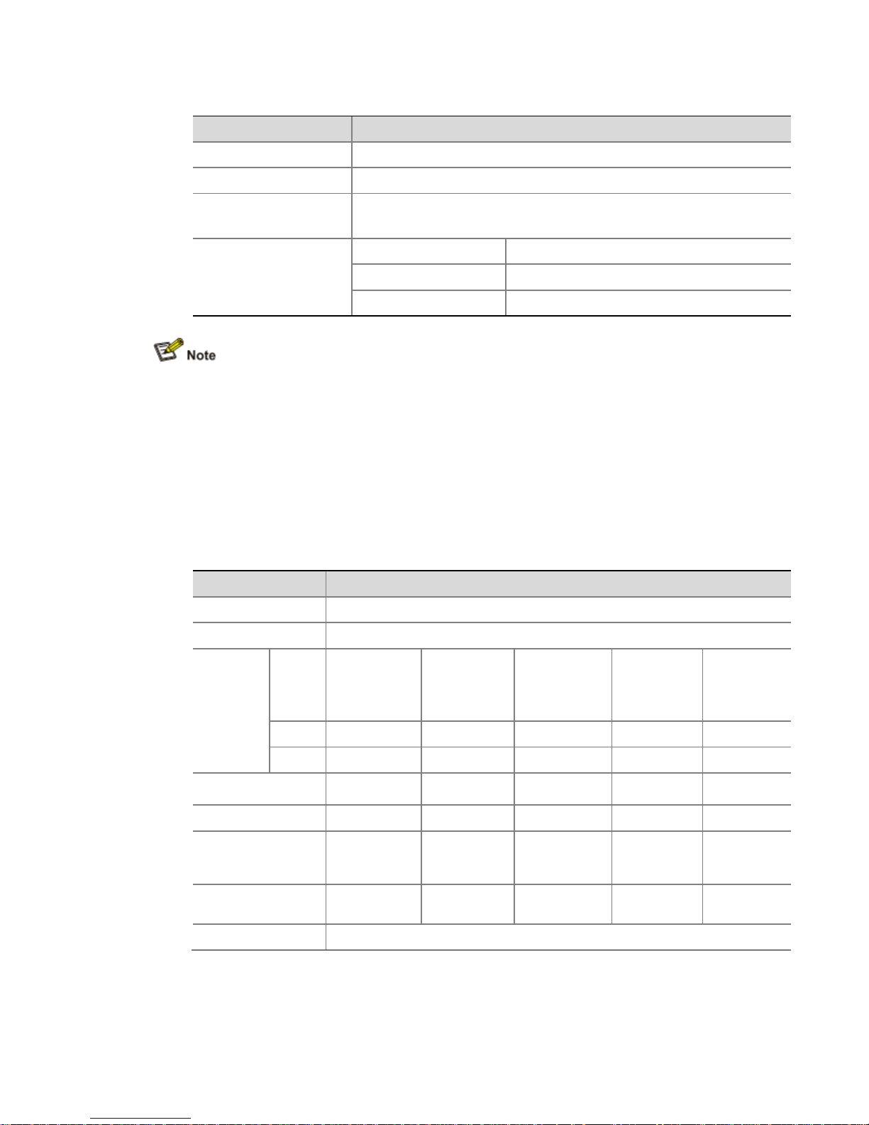
Table 1-15 Technical specifications for electrical Ethernet interfaces
Item Specification
Connector RJ-45
Interface Automatic MDI/MDI-X
Frame format
Ethernet_II
Ethernet_SNAP
Rate and duplex
10 Mbps Half/full-duplex auto-negotiation
100 Mbps Half/full-duplex auto-negotiation
1000 Mbps Full-duplex
The media dependent interface (MDI) standard is typically used on the Ethernet interface of
network adapters. The media dependent interface crossover (MDI-X) standard is typically used
on hubs or LAN switches.
When 10/100 Mbps and half duplex/full duplex are specified for an electrical Ethernet interface,
the electrical Ethernet interface operates in the forced mode. When 1000Mbps is specified or
the rate and the duplex mode are not simultaneously specified for an electrical Ethernet
interface, the electrical Ethernet interface operates in the auto-negotiation mode.
An electrical Ethernet interface supports automatic MDI/MDI-X in both the forced mode and the
auto-negotiation mode; namely, it supports both straight-through and crossover cables.
Technical specifications for optical Ethernet interfaces
Table 1-16 Technical specifications for 1000 Mbps optical Ethernet interfaces
Item Specification
Connector SFP/LC
Compliant standard 802.3, 802.3u, and 802.3ab
Optical
transmit
power
Type
Short-haul
multi-mode
optical module
(850 nm)
Medium-haul
single-mode
optical module
(1310 nm)
Long-haul
optical module
(1310 nm)
Long-haul
optical
module
(1550 nm)
Ultra-long
haul optical
module
Min –9.5 dBm –9 dBm –2 dBm –4 dBm –4 dBm
Max 0 dBm –3 dBm 5 dBm 1 dBm 2 dBm
Receiving sensitivity –17 dBm –20 dBm –23 dBm –21 dBm –22 dBm
Central wavelength 850 nm 1310 nm 1310 nm 1550 nm 1550 nm
Fiber type
62.5/125 μm
multi-mode
fiber
9/125 μm
single-mode
fiber
9/125 μm
single-mode
fiber
9/125 μm
single-mode
fiber
9/125 μm
single-mode
fiber
Maximum
transmission distance
0.55 km (0.34
miles)
10 km (6.21
miles)
40 km (24.86
miles)
40 km (24.86
miles)
70 km (43.50
miles)
Duplex 1000 Mbps in full-duplex
3) RJ-45 connector
Page 16

The 10/100/1000 Mbps electrical Ethernet interfaces of the
support automatic MDI/MDI-
X. Category
Figure 1-9
shows the appearance of an RJ
Figure 1-9 RJ-45 connector
4) LC connector
Optical fiber connectors are indispensable passive components in optical fiber communication
sy
stems. Their application enables the removable connection between optical channels, which
makes the optical system debugging and maintenance more convenient and the transit
dispatching of the system more flexible.
Some optical fiber connector types are as
LC: square optical fiber connector of the push
SC: standard optical fiber connector
FC: round optical fiber connector with screw thread
ST: round plug-
in optical fiber connector
MT-
RJ: square optical transceiver connector
Currently, the HP
SR6600 routers support only the LC
Figure 1-10 LC connector
Before using an optical fiber to connect a network device, make sure that the optical fiber
conn
ector matches the optical module.
Before connecting a fiber, make sure that the optical power at the receiving end does not
exceed the upper threshold of the optical receive power of the optical module. Otherwise, the
optical module may be dama
ged.5)Cable connecting a 1000 Mbps electrical Ethernet interface
Usually, you can use a category
interface to an Ethernet.
Figure 1
Figure 1-11 Ethernet cable
Ethernet cables
fall into the following two categories:
A6602 use RJ-
45 connectors and
-
5 twisted pair cables are used for RJ
-45 connector.
follows:
-pull snap-in type
-type connectors.
-
5 twisted pair cable to connect a 1000 Mbps electrical Ethernet
-11 shows an Ethernet cable.
-45 connectors.
Page 17

Standard cable: Also called straight-through cable. At both ends of a standard cable, wires are
crimped in the RJ-45 connectors in the same sequence. A straight-through cable is used to
connect a terminal (for example, PC or router) to a hub or LAN Switch. The cables delivered
with the A6602 are straight-through cables.
Crossover cable: At both ends of a crossover cable, wires are crimped in the RJ-45 connectors
in different sequences. A crossover cable is used to connect a terminal (for example, a PC or
router) to another terminal. You can make crossover cables by yourself as needed.
Table 1-17 Straight-through cable pinouts
RJ-45 pin Signal
Category-5
twisted pair
Signal direction RJ-45 pin
1 Tx+ White (Orange)
1
2 Tx– Orange
2
3 Rx+ White (Green)
3
4 — Blue — 4
5 — White (Blue) — 5
6 Rx– Green
6
7 — White (Brown) — 7
8 — Brown — 8
Table 1-18 Crossover cable pinouts
RJ-45 pin Signal direction
Category-5
twisted pair
Signal direction RJ-45 pin
1 Tx+ White (Orange)
3
2 Tx– Orange
6
3 Rx+ White (Green)
1
4 — Blue — 4
5 — White (Blue) — 5
6 Rx– Green
2
7 — White (Brown) — 7
8 — Brown — 8
You can refer to the table above when distinguishing between or preparing these two types of
Ethernet cables.
When preparing Ethernet cables, please follow the chromatogram given in the table to arrange
the wires. Otherwise communication quality will be affected even if the devices at both ends are
connected.
When preparing Ethernet cables, use shielded cables preferentially for electromagnetic
compatibility (EMC).
6) Fiber connecting a 1000 Mbps optical Ethernet interface
You can use a single-mode or multi-mode optical fiber to connect a 1000 Mbps optical Ethernet
interface to an Ethernet. You can select proper fibers for the installed 1000Base-FX SFP
transceiver (GE SFP for short). Since the optical interfaces on these SFP transceivers use LC
Page 18

optical connectors, you must use fibers with LC connectors. All SFP transceiver are hotswappable.
No SFP module is shipped with the A6602 unless ordered.
Use only the SFP modules provided by HP. The A6602 cannot identify SFP modules from other
manufacturers.
For the connection of electrical Ethernet interface or optical Ethernet interface cables, refer to
“Connecting Ethernet Cables” in Chapter 3 “Installing the Router”.
USB Interfaces
The universal serial bus (USB) interfaces can connect multiple types of devices and provide a
higher data transfer rate than common parallel interfaces and serial interfaces.
The A6602 fully supports USB 1.1. The USB interfaces on the router provide important storage
and security functions. For example, they provide large Flash memory space for application
programs, configuration files, and security VPN certificates to establish secure VPN connections
and secure the delivery of router configuration files.
In addition, USB interfaces provide a backup CF card mechanism to make file backup and
restoration very convenient and reliable.
Figure 1-12 USB Interfaces
(1) USB interface 0 (2) USB interface 1 (3) USB interface 1 LED
USB0
USB interface 0 on the A6602 is a USB 1.1-compliant type-A interface. USB interface 0 can be
connected to an external USB storage device to expand the router’s space for storing files and
logs and facilitate file transfer.
Insert and remove a USB storage device correctly. Otherwise, the software, hardware and file
system of the USB storage device may get damaged.
After you insert a USB storage device and information is displayed on the terminal, prompting
the USB storage device is inserted into the A6602, the LED on the USB storage device will be
on.
When the LED on the USB storage device is blinking, do not remove the USB storage device.
Before removing the USB storage device, execute the umount usba0: command in user view
to unmount the USB storage device. If information is displayed on the terminal, prompting the
USB storage device is successfully unmounted, you can remove the USB storage device. After
the USB storage device is removed, information will also be displayed on the terminal, showing
the USB storage device has been removed.
The A6602 only supports the USB storage devices provided by HP and may be incompatible
with those from other manufacturers.
For details about the umount command, refer to HP SR6600 Routers User Manual.
Page 19

USB1
USB interface 1 on the A6602 is a USB 1.1-compliant type-B interface. USB interface 1 can be
connected to a terminal or computer through a standard cable. After the interface is enabled,
the built-in CF card of the A6602 is recognized as an external storage device by the computer
and you can access the internal CF card quickly and perform file operations on it.
Table 1-19 describes the USB interface 1 LED.
Table 1-19 Description of USB interface 1 LED
Status Meaning
Solid green A link is present.
Blinking green Data is being received or transmitted. In this state, do not unplug the USB cable.
Interface Modules
The A6602 provides two HIM/MIM slots, in which you can insert a HIM and a MIM, or two HIMs,
or two MIMs. HIMs and MIMs are hot-swappable.
For the installation and removal of HIMs and MIMs, refer to Chapter 6 “Maintaining Hardware”.
“Hot-swapping” a module refers to first using the remove slot number command to stop the
module and then pulling it out manually, or inserting the module into its slot without powering off
the device.
RESET Button
To reset the router, you can press the RESET button.
The SYS LED goes off when the router is reset, flashes fast (at 8 Hz) when it is booting, and
flashes slowly (at 1 Hz) when it operates normally.
If you perform no save operation before resetting the router, the current system configuration
will not be saved after the router is reset.
Never press the RESET button when the router is booting (when the SYS LED is blinking fast).
Otherwise, the file system of the router may be damaged.
AC Power Input
Table 1-20 lists the AC input power specifications for the A6602.
Table 1-20 AC input power specifications for the A6602
Item Specification
Rated voltage range 100 VAC to 240 VAC; 50 Hz or 60 Hz
Maximum input current 2.5 A
Maximum power 150 W
Page 20

Clock
The A6602 router is designed with a clock module that provides the system time. You can set
the system time on the command line interface.
Use the clock datetime time date command in user view to set the system date and time. For
the description of the clock datetime command, refer to HP SR6600 Routers User Manual.
When a power failure occurs to the router, the clock module can continue working to ensure the
system time is correct next time the router boots. With the router powered off, the clock module
can work for at least 10 years.
When the router is powered on, pay attention to the following points:
Never replace the clock module battery.
The system time gets lost once the battery of the clock module is removed, and you need to set
the system time again on the command line interface. However, the system time will still get lost
after the router is powered off.
You can use the clock datetime, clock summer-time one-off (or clock summer-time
repeating), and clock time zone commands to set the system date and time. For details about
these commands, refer to HP SR6600 Routers User Manual.
RPS (Optional)
The redundancy power supply (RPS) can provide power supply to maintain the normal system
operation for a short period when the system power supply fails.
The RPS uses a control pin to control its output status. When the system power supply fails, it
sends a LOW signal to the control pin of the RPS. Upon receiving the LOW signal, the RPS
switches to the output status within 10 ms and starts to supply power to the router.
The A6602 supports AC power input and RPS input. They can guarantee the router to continue
working when one power supply fails, thus providing high reliability.
Table 1-21 Specifications for the RPS of the A6602
Specification Value
Rated output voltage 12 V
Maximum output current 14 A
Maximum output power 168 W
The RPS is an optional component not shipped with the router.
For the RPS installation, refer to “Connecting the RPS DC Power Cable” in Chapter 3 “Installing
the Router”.
Port Lightning Arrester (Optional)
Before connecting an outdoor Ethernet cable to an Ethernet port, you can install a port lightning
arrester to protect the router against lightning strokes.
The following port lightning arrester can be installed on the A6602. The specifications for the
port lightning arrester are as follows:
Port protective unit–single port, maximum discharge current (8/20μs waveform): 5 kA, output
voltage (10/700μs waveform): core-core < 40 V, core-ground < 600 V.
Page 21

For the installation of the port lightning arrester, refer to “Installing a Port Lightning Arrester
(Optional)” in Chapter 3 “Installing the Router”.
Power Lightning Arrester (Optional)
Before connecting an outdoor AC power supply to the router, you need to install a lightning
protection busbar at the AC power input end and then connect the AC power cord to the
lightning protection busbar to protect the router against lightning strokes. In a heavy lightning
area, you are recommended to install a power lightning arrester.
The following power lightning arrester can be installed on the A6602. The specifications for the
power lightning arrester are as follows:
Maximum discharge current: 6500 A, protection voltage: 220 VAC to 500 VAC.
For the installation of the power lightning arrester, refer to “Installing a Power Lightning Arrester
(Optional)” in Chapter 3 “Installing the Router”.
Signal Lightning Arrester (Optional)
Generally, you need to connect a signal lightning arrester (namely, a transient over-voltage
protection) before connecting a signal cable to the router. This can protect electronic devices
against surge over-voltage resulting from lightning strokes and other interferences, and
minimize impact on the router.
The A6602 supports three types of signal lightning arresters:
Voltage-limiting protection-signal lightning arrester-maximum discharge current
2.5KA/protection voltage 25V--SMB-75J/SMB-75J-1W-10Mbps.
Voltage-limiting protection-signal lightning arrester-maximum discharge current
2.5KA/protection voltage 25V-BNC-75K/BNC-75K-10Mbps.
Voltage-limiting protection-signal lightning arrester (U port)-maximum discharge current
3KA/common mode 400 V/differential mode 170V-RJ11.
For the installation of the signal lightning arrester, refer to “Installing a Signal Lightning Arrester
(Lightning Protection Busbar) (Optional)” in Chapter 3 “Installing the Router“.
System Software
The A6602 uses the Comware V5 software platform, HP's core software platform.
Based on the IPv4/IPv6 dual stack, the Comware V5 software platform integrates data
communications features such as link-layer protocols, Ethernet switching, intelligent resilient
framework (IRF), routing, Multi-Protocol Label Switching (MPLS), Virtual Private Network (VPN),
Quality of Service (QoS), security and multicast. It is one of the most mature network operating
systems. The Comware V5 software platform is scalable and portable because it adopts a
componentized architecture and effectively encapsulates and masks different operating
systems and hardware.
Page 22

2 Preparing for Installation
Environment Requirements
The A6602 is designed for indoor application. To ensure the normal operation and prolong the
service life, the installation site must meet the requirements mentioned hereunder.
Temperature and Humidity Requirements
The temperature and humidity in the equipment room shall be maintained at an appropriate
level.
A long-term high relative humidity will quite likely result in poor insulation
performance, electric leakage, mechanical property change, and corrosion.
A long-term low relative humidity will result in looseness of fastening screws owing
to shrinkage of insulation washers, or electrostatic discharge (ESD), which may
damage the CMOS circuit on the router.
A high temperature will speed up the aging of insulation materials, which greatly
lowers the router’s reliability and shortens the service life.
Table 2-1 lists the requirements on temperature and humidity for the A6602.
Table 2-1 Temperature and humidity requirements in the equipment room
Temperature Relative humidity
0°C to 45°C (32°F to 113°F) 10% to 95% (noncondensing)
Cleanness Requirements
Concentration limit of dust
Dust is harmful to the safe operation of the router. Dust on the chassis may result in static
adsorption, which causes poor contact between metal connectors or joints. The poor contact
may not only shorten the service life of the router, but also bring about communication
failures. Especially under the condition of low indoor humidity, dust is more likely to occur,
causing static adsorption.
Table 2-2 lists the requirements on the dust concentration and diameters in the equipment
room.
Table 2-2 Limitation on dust concentration and diameter in the equipment room
Diameter (μm) 0.5 1 3 5
Concentration limit
(particles/m3)
1.4×10
7
7×10
5
2.4×10
5
1.3×10
5
Page 23

Concentration limit of harmful gases
Besides, the contents of salt, acid, and sulfide in the equipment room of the router should be
strictly restricted. Harmful gases could accelerate the corrosion of metal parts and the aging of
some parts. Table 2-3 lists the concentration limit of SO2, H2S, NH3, and CI2in the equipment
room.
Table 2-3 Concentration limit of some harmful gases in the equipment room
Gas Max (mg/m3)
SO
2
0.2
H2S 0.006
NH
3
0.05
Cl
2
0.01
Ventilation Requirements
The fans of the A6602 draw air in through the inlet vents on the left and out through the
exhaust vents on the right.
Figure 2-1 Ventilation method for the A6602
Make sure that:
There is a minimum clearance of 10 cm (3.9 in) around the inlet vents and exhaust
vents for heat dissipation of the router chassis.
A ventilation system is available at the installation site.
Electrostatic Discharge Prevention
Generation and damage of static electricity
In the communication network to which the router is connected, static induction mainly
results from:
Page 24
External electrical fields such as outdoor high voltage power line or lightning
Indoor environment, flooring materials, and the router structure
Although many antistatic considerations have been given to the A6602, damage to board
circuits or even the router may still happen when the static electricity exceeds a certain limit.
Measures against ESD
To prevent electrostatic discharge (ESD),
Make sure that the router and the floor are well grounded.
Take dust-proof measures for the equipment room.
Maintain the humidity and temperature at a proper level, respectively.
Wear an ESD-preventive wrist strap when touching a circuit board or optical
interface module.
Place the removed memory module, CF card, or HIM/MIM on an antistatic
workbench, with the face upward, or put it into an antistatic bag.
Touch only the edges, instead of electronic components when observing or moving
a removed memory module, CF card, or HIM/MIM.
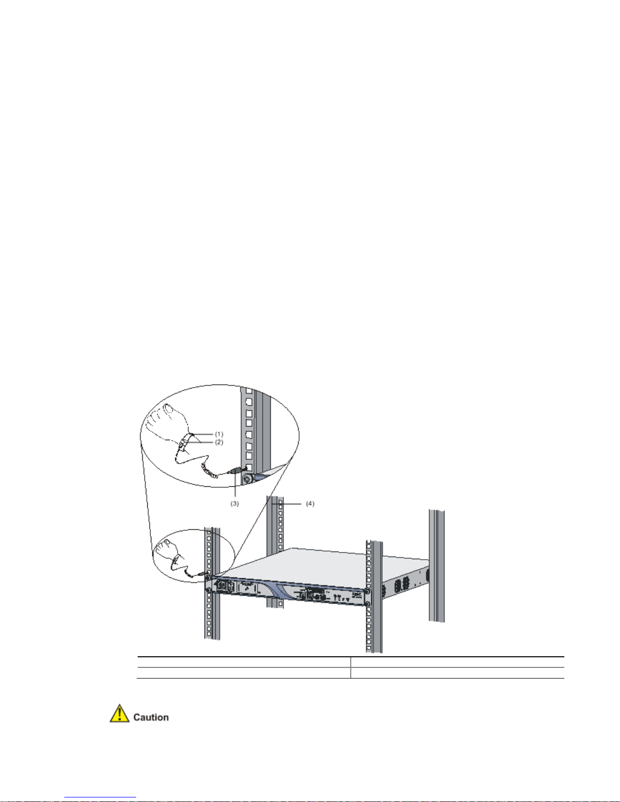
Connection of the ESD-preventive wrist strap
Follow these steps to connect the ESD-preventive wrist strap:
Step1 Put on the ESD-preventive wrist strap, ensuring the strap makes good skin
contact.
Step2 Attach the alligator clip to the rack.
Step3 Make sure that the rack is well grounded.
Figure 2-2 Connect the ESD-preventive wrist strap
(1) ESD-preventive wrist strap (2) Snap fastener
(3) Alligator clip (4) Rack
Page 25

For the sake of safety, check the resistance of the ESD-preventive wrist strap. The
resistance reading should be in the range of 1 to 10 megohms between human body and
the ground.
The ESD-preventive wrist strap is user-supplied.
Electromagnetic Interference Prevention
All possible interference sources, external or internal, affect the router in the way of
capacitance coupling, inductance coupling, electromagnetic radiation, and common
impedance (including the grounding system) coupling. To minimize the influence of
interference sources on the router, you should take the following into consideration:
Take effective measures to protect the power system from the power grid system.
Separate the protection ground of the router from the grounding device or lightning
protection grounding device of the power supply equipment as far as possible.
Keep the router far away from radio stations, radar, and high-frequency devices
working in high current.
Use electromagnetic shielding when necessary.
Lightning Protection
Although many measures have been taken to protect the A6602 from lightning, if the lightning
intensity exceeds a certain range, damage to the router may still happen. To protect the router
from lightning better, you are recommended to do as follows:
Ensure the PGND cable of the chassis is well grounded.
Ensure the grounding terminal of the AC power socket is well grounded.
Install a lightning arrester at the input end of the power supply to enhance the
lightning protection capability of the power supply.
Install a special lightning arrester at the input end of outdoor signal lines (for
example, E1/T1 line) to which interface modules of the router are connected to
enhance the lightning protection capability.
Refer to Chapter 3 “Installing the Router” for the connection of the PGND cable and the
installation of the power lightning arrester and signal lightning arrester.
Workbench Requirements
When installing the router on a workbench, make sure that:
The workbench is sturdy enough to support the weight of the router and installation
accessories.
The workbench is well grounded.
Cabinet-Mounting Requirements
When installing the router in a cabinet,
Page 26

Install the router in an open cabinet if possible. If you install the router in a closed
cabinet, make sure that the cabinet is equipped with a good ventilation system.
Make sure that the cabinet is sturdy enough to support the weight of the router and
installation accessories.
Make sure that the size of the cabinet is appropriate for the router, and that there is
enough clearance around the left and right panels of the router for heat dissipation.
For the sake of heat dissipation and device maintenance, it is recommended that
the front and rear of the cabinet should be at least 0.8 m (31.5 in.) away from walls
or other devices, and that the headroom in the equipment room should be no less
than 3 m (9.84 ft).
Safety Precautions
Installation and removal of the unit and its accessories must be carried out by qualified
personnel. You must read all of the Safety Instructions supplied with your device before
installation and operation.
Installation und Ausbau der Anlage und ihrer Zubehörteile müssen von qualifiziertem Personal
realisiert werden. Sie müssen vor der Installation oder Bedienung allen beiliegenden
Sicherheitshinweise lesen.
负责安装和日常维护本设备的人员必须具备安全操作基本技能。在操作本设备前,请务必认真阅
读和执行产品手册规定的安全规范。
Safety Signs
When reading this manual, pay attention to the following:
Means the reader be extremely careful. Improper operation may cause device
damage or bodily injury.
Means the reader be careful. Improper operation may cause device
malfunction.
General Safety Recommendations
Keep the router chassis and installation tools away from walk area.
Keep the router far away from a moist area and heat sources.
Unplug all external cables before moving the chassis.
Page 27

Electricity Safety
Locate the emergency power switch in the equipment room before installation and
maintenance so that you can switch the power off in case of an electrical accident. If
necessary, unplug the power cord immediately.
Make sure that the router has been correctly grounded.
Do not open or close the chassis cover when the router is powered on.
Connect the interface cables for the router correctly.
Use laser with caution. Do not directly stare into apertures or fiber-optic connectors
that emit laser radiation.
If you are not using the laser, cover the dust cover to avoid static adsorption, which
may cause damage to the laser.
Equip an uninterrupted power supply (UPS).
Disconnect the two power inputs to power off the router if there are two power
inputs.
Avoid maintaining the router alone when it is powered on.
Installation Tools, Meters and Devices
Installation Accessories Supplied with the Router
AC power cord
Console cable
PGND cable
Front and back rack-mounting ears
User supplied tools
Phillips screwdrivers: P1-100 mm, P2-150 mm, and P3-250 mm
Straight screwdriver: P4-75 mm
Screws with various specifications
Various meters and devices, such as hub, configuration terminal, optional modules,
and multimeter.
Optional cables
ESD-preventive glove, ESD-preventive wrist strap, antistatic bag or mat
Reference
When installing or maintaining the A6602, you can refer to the following documents shipped
with the A6602:
HP A6602 Router Installation Manual
HP SR6600 Routers Electronic Documentation
Or, you can obtain the latest documents from the documentation center on the website at
http://www.HP.com.
Checklist Before Installation
Table 2-4 Checklist before installation
Item Requirements
Installation site Ventilation
There is a minimum clearance of 10 cm (3.9 in.) around the inlet
vents and exhaust vents for heat dissipation of the router chassis.
Page 28

A ventilation system is available at the installation site.
Temperature 0°C to 45°C (32°F to 113°F)
Relative humidity 10% to 95% (noncondensing)
Cleanness Dust concentration ≤ 3 × 10⁴particles/m
3
ESD prevention
Theequipment and the floor are well grounded.
Theequipment room is dust-proof.
Thehumidity and temperature are at a proper level, respectively.
Wear an ESD-preventive wrist strap and uniform when touching a
circuit board.
Place the removed memory module, CF card, or HIM/MIM on an
antistatic workbench, with the face upward, or put it into an
antistatic bag.
Touch only the edges, instead of electronic components when
observing or moving a removed memory module, CF card, or
HIM/MIM.
EMI prevention
Take effective measures to protect the power system from the
power grid system.
Separate the protection ground of the router from the grounding
device or lightning protection grounding device as far as possible.
Keep the router far away from radio stations, radar and high-
frequency devices working in high current.
Useelectromagnetic shielding when necessary.
Lightning
protection
ThePGND cable of the chassis is well grounded.
Thegrounding terminal of the AC power socket is well grounded.
A port lightning arrester is installed. (Optional)
A power lightning arrester is installed. (Optional)
A signal lightning arrester is installed at the input end of an
external signal cable. (Optional)
Electricity safety
Equipan uninterrupted power supply (UPS).
In case of emergency during operation, switch off the external
power switch.
Workbench
Theworkbench is stable enough
Well grounding
Cabinet-mounting
requirements
Install the router in an open cabinet if possible. If you install the
router in a closed cabinet, make sure that the cabinet is equipped
with a good ventilation system.
The rack is sturdy enough to support the weight of the router and
installation accessories.
The size of the cabinet is appropriate for the router.
The front and rear of the cabinet are at least 0.8 m (31.50 in.)
away from walls or other devices.
Safety
precautions
The router is far away from any moist area and heat source.
The emergency power switch in the equipment room is located.
Tools
Installation accessories supplied with the router
User supplied tools
Reference
Documents shipped with the router
Online documents
Page 29

3
Installing the Router
Preparations
Before installing the router, make sure that:
You have read through Chapter 2 “Preparing for Installation”.
Make sure all the requirements mentioned in Chapter 2 “Preparing for
are satisfied.
Installation Flowchart
Figure 3-1
Installation flowchart for the
Installing the Router to the Specified Position
You can install the router on a workbench or in a rack.
A6602
Installation”
Page 30

Installing the Router on a Workbench
If a 19-in
ch rack is not available, you can install the router on a clean workbench. During
installation, make sure:
The length and width of the workbench are larger than the distance between the
feet of the router. See
Table 3-1
Dimensions of the
Dimensions without feet and mounting brackets (H ×
W × D)
The workbench is steady and well grounded.
The workbench is solid enough to support the weight of the router and installation
accessories.
There is a minimum clearance of 10 cm (3.9 in.) around the router for heat
dissipati
on of the router chassis.
No heavy object is placed on the router for fear of device damage and poor heat
dissipation.
Installation the Router in a Rack
Installing an N68 rack
The A6602
can be installed in an
N68 Cabinet Installation and Remodel Introduction
Installing mounting-
brackets onto the router
1)
Structure of the mounting
Figure 3-2
Structure of mounting
(1) Left front mounting-
bracket
(3) Left rear mounting-
bracket
2)
Install the front mounting
Before installing the router in the rack, fix the left and right front mounting
respectively to the
left and right sides of the front panel of the router.
install them.
Table 3-1 for the dimensions of the router.
A6602
Item
Description
44 × 442 × 460
mm (1.73 × 17.4 × 18.1 in.)
HP N68 rack. For the installation of
an N68 rack, refer to
.
-brackets
-brackets
(2) Right fro
nt mounting
(4) Right rear mounting
-brackets to the router
-
brackets
Figure 3
HP
-bracket
-bracket
-3 shows how to
Page 31

Figure 3-3 Install the front mounting-brackets to the router
Installing the router in a rack
Follow these steps to install the router in a rack:
Step1 Check the grounding and stability of the rack and use screws to fix the rear
mounting-brackets onto both sides of the rack.
Step2 After installing the front mounting-brackets, fix two screws on the upper central
part of the left and right sides of the router so that the router can be fixed on the rear
mounting-brackets.
Figure 3-4 Install a screw on the upper central part of each side of the router
Step3 Put the router on the rack and fix it with the left and right rear mounting-
brackets.
Figure 3-5 Install the router in the rack
(1) Rack
(2) Screw attached to the right rear mounting bracket for supporting the router
(3) Right rear mounting-bracket (4) Right front mounting-bracket
Page 32

Step4 Fix the router in the rack horizontally and firmly by fastening the mountingbrackets onto the rack posts with pan-head screws. The size of pan-head screws should
satisfy the installation requirements (maximally M6) and the surface of the screws should
be anti-rust.
Figure 3-6 Fix the front mounting-brackets
Installing Generic Modules
Generic modules include memory module, CF card, HIM, and MIM. For their installation
procedures, refer to Chapter 6 “Maintaining Hardware”.
PGND Cable Connection
Importance of the PGND Cable
The correct connection of the protection ground (PGND) cable on the router chassis is an
essential safeguard against the lightning strokes and EMI. You need to correctly connect the
PGND cable when installing or using the router.
The AC power input end of the A6602 is equipped with a noise filter. The neutral ground of the
power input end is directly connected to the chassis and is called PGND (also known as chassis
ground). You need to securely connect the PGND cable to the earth ground to safely lead
induced current and leakage current to the ground and reduce the EMS of the router. The
PGND cable can also protect the router against high lightning voltage resulting from external
network lines such as E1/T1.
Page 33

Connecting the PGND Cable
The grounding screw of the
A6602
and is marked with a grounding sign, as shown in
Figure 3-7
Connect the PGND cable
(1) Grounding screw
(3) Grounding screw hole
(5) PGND cable
Follow these steps to connect the PGND cable:
Step1
Remove the grounding screw from the router chassis.
Step2
Put the OT terminal of the supplied PGND cable on the grounding screw.
Step3
Fasten the grounding screw into the grounding screw hole with a screwdriver.
Step4
Connect the other en
cabinets installed in equipment rooms are equipped with a grounding bar.
If a grounding bar is available, you can connect the PGND cable of the router to the
grounding bar as follows: a) Use a cable stripper to strip off the insulation rubber
about 15 mm (0.59 in.) from the PGND cable. b) Wrap the naked part onto the
grounding post of the grounding bar. c) Fix the PGND cable onto the grounding post
with a hex nut.
If no grounding bar is available, connect the naked part of the PGND cable to the
ground directly.
Figure 3-8
Connect the PGND cable to the groun
(1) Hex nut
(3) Naked part of the PGND cable
is located on the lower left corner
of the rear chassis panel
Figure 3-7.
(2) OT terminal
(4) Grounding sign
d of the PGND cable to the ground. Generally, the
ding bar
(2) PGND cable
(4) Grounding post
Page 34

(5) Grounding bar
The resistance between the router chassis and the ground must be less than 5 ohms.
Use the PGND cable provided with the router to connect the ground bar in the equipment
room. Otherwise, the router may not be effectively grounded, which easily causes damage
to the router.
Installing a Port Lightning Arrester (Optional)
Only 10/100 Mbps RJ-45 Ethernet ports need to be equipped with port lightning arresters.
No port lightning arrester is shipped with the router unless ordered.
Before connecting an outdoor Ethernet cable to an Ethernet port, you can install a port
lightning arrester to protect the router against lightning strokes.
The following port lightning arrester can be installed on the A6602. The specifications for the
port lightning arrester are as follows:
Port protective unit–single port, maximum discharge current (8/20μs waveform): 5 kA, output
voltage (10/700μs waveform): core-core < 40 V, core-ground < 600 V.
Tools
Phillips or flathead screwdriver
Multimeter
Diagonal pliers
Installation Procedure
Follow these steps to install a port lightning arrester:
Step1 Use a double-faced adhesive tape to stick the port lightning arrester to the
router. The port lightning arrester should be as close to the grounding screw as possible.
Step2 Cut short the grounding cable of the port lightning arrester according to its
distance to the grounding screw. Then, fix the grounding cable onto the grounding screw
of the router.
Step3 Use the multimeter to check the connection between the grounding cable of the
port lightning arrester and the grounding screw of the router.
Step4 Follow the instructions to connect the port lightning arrester with a transit cable.
(Note that the external cable should be connected to the IN end while the transit cable
should be connected to the OUT end.) Check whether the LED on the interface module
is normal.
Page 35

Read the instructions carefully before installing the port lightning arrester.
Step5
Bundle the cables with nylon cable ties neatly.
Figure 3-9
Install a port lightning arrester
Precautions
Pay attention t
hat the performance of the port lightning arrester may be affected in the
following cases:
The IN and OUT ends of the port lightning arrester are connected incorrectly.
end should be connected to the external cable, while the OUT end shou
connected to the Ethernet port of the router.
The port lightning arrester is not well grounded.
of the port lightning arrester should be as short as possible and be well connected to
the grounding screw o
connection.
The installed port lightning arresters are not sufficient.
Ethernet cable is connected to the router, you need to install a port lightning arrester
fo
r each outdoor Ethernet cable.
Installing a Power Lightning Arrester (Lightning Protection
Busbar) (Optional)
No power lightning arrester is shipped with the router. You should purchase one if needed.
Before connecting an outdoor AC power supply to t
protection busbar at the AC power input end and then connect the AC power cord to a
Make sure that the grounding cable
f the router. You need to check with a multimeter after
When more than one outdoor
he router, you need to install a lightning
The IN
ld be
Page 36

lightning protection busbar to protect the router against lightning strokes. You can use cable
ties and screws to fasten the ligh
wall in the equipment room.
Figure 3-10
Install a power lightning arrester
Note that:
1)
Make sure that the protection wire (PE) terminal of the power lightning arrester is
well groun
ded before using it.
2)
After the AC power cord of the router is plugged into the multi
power lightning arrester (lightning protection busbar), if the green LED is ON and the
red LED is OFF, the lightning protection can functio
3)
Pay attention and clear the alarm if the red LED is ON. You should correctly tell
whether the grounding cable is not well connected or the live and zero wires are
connected reversely. When the red LED is ON, use a multimeter to examin
polarity at the multi
If the live and zero wires are on the left and right respectively (supposing that you
are facing the socket), the PE terminal of the power lightning arrester is not
grounded.
If the live and zero wires are on the right and left respec
are facing the socket), the polarity of the power socket of the power lightning
arrester is reversed. In this case, you should open the power socket to correct the
polarity. After that, if the red LED is still ON, you can make su
of the power lightning arrester is not grounded.
Installing a Signal Lightning Arrester (Optional)
No signal lightning arrester is shipped with the router. You should purchase one if needed.
tning protection busbar on the cabinet, the workbench, or the
-
purpose socket of the
n normally.
-purpose socket of the power lightning arrester.
tively (supposing that you
re that the PE terminal
e the
Page 37

Generally, you need to connect a signal lightning arrester (namely, a transient over-voltage
protection) before connecting a signal cable to the router. This can protect electronic devices
against surge over-voltage resulting from lightning strokes and other interferences, and
minimize impact on the router.
Because the signal lightning arrester is serially connected to a signal cable, the signal lightning
arrester must satisfy the requirements of network performance indexes such as data
transmission bandwidth, as well as the lightning protection performance requirement.
Therefore, before installing a signal lightning arrester, you need to consider such performance
indexes of the lightning arrester as lightning protection, bandwidth, transmission loss, and port
type.
The A6602 supports three types of signal lightning arresters:
Voltage-limiting protection – signal lightning arrester – maximum discharge current
2.5KA/protection voltage 25V--SMB-75J/ SMB-75J-1W-10Mbps
Voltage-limiting protection – signal lightning arrester – maximum discharge current
2.5KA/protection voltage 25V-BNC-75K/ BNC-75K-10Mbps
Voltage-limiting protection – signal lightning arrester (U port) - maximum discharge
current 3KA/common-mode 400V/differential mode 170V-RJ11
The signal lightning arrester should be grounded as near as possible. The grounding
resistance must be less than 4 ohms. The grounding resistance must be less than 1 ohm if
there are special grounding requirements.
Connect the grounding cable to the special-purpose grounding cable of the signal lightning
arrester and connect it to the earthing network, instead of connecting it to the lightning rod
or lightning belt.
Connecting the Power Cables
Power Supply Port and PGND Terminal
The A6602 only supports AC power input. The AC power socket and power switch are located
on the left of the front panel, as shown in Figure 3-11.
Figure 3-11 AC power socket
(1) Bail latch holder (2) AC power socket (100 VAC to 240 VAC; 50/60Hz; 2.5A)
(3) Power switch (ON/OFF)
Page 38

For the specifications for the AC power socket, see Table 3-2.
Table 3-2 Technical specifications for the AC power socket of the A6602
Item Specification
AC power socket 100 VAC to 240 VAC
Connecting the AC Power Cord
AC power supply
Rated voltage range: 100 VAC to 240 VAC, 50 Hz/60 Hz.
AC power socket
Use a three-terminal, single-phase power connector with a grounding contact
Ground the power supply reliably. Normally, the grounding contact of the power
supply system in a building was buried during construction and cabling.
Before connecting the AC power cord, make sure that the power supply of the
building is well grounded.
Connection procedure
Follow these steps to connect the AC power cord:
Step1 Make sure that the PGND terminal is securely connected to the ground.
Step2 Move the power switch to the OFF position.
Step3 Move the bail latch upward.
Step4 Connect one end of the supplied AC power cord to the power socket on the
router, and the other end to the power source.
Step5 Move the bail latch downward to hold the power cord in position.
Step6 Move the power switch to the ON position.
Step7 Check the status of the PWR LED on the front panel of the router. For the
status of the power LED, see Table 3-3.
Table 3-3 Status of the power LED
Color Status
OFF There is no power input.
ON The power module works abnormally.
Figure 3-12 Connect the AC power cord
(1) Bail latch holder (2) AC power plug
(3) Power switch (4) AC power socket (100 V to 240V; 50/60Hz; 2.5A)
(5) Bail latch (6) AC power cord
Page 39

Connecting the RPS DC Power Cable
Follow these steps to connect the RPS DC power cable:
Step1 Make sure that the power switch on the router and the RPS input power switch
are both off.
Step2 Rip off the adhesive tape from the RPS socket.
Step3 Loosen the screws on the RPS blank panel with a Phillips screw.
Figure 3-13 Loosen the screws on the RPS blank panel
Step4 Shake the blank panel slightly and then take it off. Now, you can see the RPS
socket.
Figure 3-14 RPS socket
Step5 Plug the RPS power cable into the RPS socket on the router.
Step6 Turn the screws on the RPS connector clockwise to make the connector
plugged in completely, and then fasten the two strain-relief screws on the RPS
connector.
Figure 3-15 Connect the RPS DC power cable to the router
Step7 Connect the other end of the RPS cable to the RPS DC output socket.
Page 40

Figure 3-16 Connect the RPS DC power cable to the RPS DC output socket
(1) RPS socket (2) Connector for the RPS socket
(3) RPS DC power cable (4) RPS AC input socket
(5) RPS power switch (ON/OFF) (6) Connector for the RPS DC output socket
(7) RPS DC output socket (8) RPS
Step8 Turn on the power switch on the router and the RPS power switch.
Step9 Check the status of the OK LED on the RPS front panel. If it is on, the RPS
power works normally.
Connecting Port Cables
Connecting the Console Cable
Follow these steps to connect the console cable:
Step1 Select a configuration terminal.
The configuration terminal can be a standard ASCII terminal with an RS232 serial port, or a
common PC.
Step2 Connect the console cable.
Disconnect the power supply to the router. Connect the RJ-45 connector of the console cable
to the console port on the router, and the DB-9 (female) connector to the serial port on the
configuration terminal.
Step3 Power on the router after verifying the connection.
Verify the connection and power on the router. The configuration terminal displays the startup
banner of the router if the connection is correct. For details, refer to “Router Power-on” in
Chapter 4 “Starting and Configuring the Router”.
Page 41

Figure 3-17 Connect the console cable
(1) Console port (2) DB-9 (female) connector
(3) Serial port on the configuration terminal (4) Console cable
(5) RJ-45 connector
When connecting a PC to the router with the console cable, first connect the DB-9 connector to
the serial port on the PC, and then the RJ-45 connector to the console port on the router.
Connecting the AUX Port to a Modem
The AUX port is usually used for remote configuration or dial backup. In this case, you need to
connect the local modem to the remote modem through PSTN and then to the remote device.
Follow these steps to connect the AUX port with an AUX cable.
Step1 Plug the RJ-45 connector of an AUX cable into the AUX port on the router.
Step2 Plug the DB-25 (male) or DB-9 (male) connector into the serial port on the
analog modem.
Page 42

Figure 3-18 Connect the AUX cable
(1) AUX port (2) RJ-45 connector
(3) AUX cable (4) Modem
(5) DB-25 (male) or DB-9 (male) connector
Connecting Ethernet Cables
Connecting an electrical Ethernet port
Step1 Connect one end of an Ethernet cable to an electrical Ethernet port on the
A6602 and the other end to the Ethernet port on the peer device. Because a 10BaseT/100Base-TX/1000Base-T fixed electrical Ethernet port supports MDI/MDIX autosensing, you can use a straight-through cable or crossover cable to connect the port.
Step2 Check the status of the LED of the fixed electrical Ethernet port after power-on.
For the status of the LED, see Table 3-4.
Table 3-4 Status of the LED
LED Color Status
GE0 to GE3
(yellow/green)
Off No link is present.
Solid green A 1000 Mbps link is present.
Flashing green Data is being transmitted/received at 1000 Mbps.
Solid yellow A 10/100 Mbps link is present.
Flashing yellow Data is being transmitted/received at 10/100 Mbps.
Connecting an optical Ethernet port
Follow these steps to connect a 1000 Mbps optical Ethernet port:
Step1 Remove the dust cover from the optical Ethernet port.
Page 43

Figure 3-19 Remove the dust cover
Step2 Align an SFP module with the optical SFP port, with the module handle facing
outward. Then insert it into the optical SFP port.
Figure 3-20 Insert an SFP module
Step3 Identify the Rx and Tx ports on the SFP module. Plug the LC connector at one
end of one fiber cable into the Rx port of the router and the LC connector at the other
end into the Tx port of the peer device. Plug the LC connector at one end of another fiber
cable into the Tx port of the router and the LC connector at the other end to the Rx port
of the peer device.
Page 44

Figure 3-21
Plug fiber connectors
Step4
View the SFP LED after power
5.
Table 3-5
Status of the SFP LED
LED
SFP0 to SFP3
(yellow/green)
Off
Solid green
Flashing green
Solid yellow
Note that:
Avoid excessi
vely bending optical fiber cables, with the curvature radius less than
10 cm (3.9 in.).
Ensure that the Tx and Rx ports of the SFP module are connected correctly.
Keep the end-
faces of optical fiber cables clean.
Never
stare into an open SFP interface on the interface module, because invisible rays
may be emitted from the SFP interface.
Cover the dust cover if no optical fiber connector is connected to the SFP interface.
-
on. For the status of the SFP LED, see
Color
Status
No optical link is present.
A 1000 Mbps optical link is present.
Data is being transmitted/received at a rate of 1000 Mbps.
The SFP module fails to be detected.
Table 3-
Page 45

Verifying Installation
Each time you power on the router during installation, you must verify that:
There is enough space around the router for heat-dissipation and the workbench is
stable enough.
The power supply matches the requirements of the router.
The PGND cable of the router is correctly connected.
The router is correctly connected to the configuration terminal and other devices.
It is very important to verify the installation because the stability and grounding of the router and
the power supply will directly affect the operation of the router.
Page 46

4 Starting and Configuring the Router
You can use only the console port to make initial configuration of the A6602.
Setting Up the Configuration Environment
Connecting the Router to a Configuration Terminal
For how to connect the router to the configuration terminal, refer to “Connecting the Console
Cable” in Chapter 3 “Installing the Router“.
Setting the Parameters for the Console Terminal
Step1 Create a HyperTerminal connection. Select Start > Programs > Accessories >
Communications > HyperTerminal, and enter a connection name in the Connection
Description dialog box, as shown below.
Figure 4-1 Create a connection
Step2 Select a connection port. Select a serial port from the Connect using drop-down list in the
Connect to dialog box, as shown below. Be sure to select the serial port to which the console
cable is actually connected.
Page 47

Figure 4-2 Select a port for local configuration connection
Step3 Set serial port parameters.
Set the properties of the serial port in the COM1 Properties dialog box, as shown in Figure 4-3.
Table 4-1 Set serial port parameters
Item Value
Bits per second 9600 bps (default)
Data bits 8
Parity None
Stop bits 1
Flow control None
To use the default settings, click Restore Defaults.
Page 48

Figure 4-3 Set serial port parameters
Step4 Click OK after setting the serial port parameters to enter the HyperTerminal window, as shown
below.
Figure 4-4 HyperTerminal window
Step5 Set HyperTerminal properties. In the HyperTerminal window, select File > Properties from the
menu, and select the Settings tab to enter the properties setting dialog box, as shown below.
Select VT100 or Auto detect from the Emulation drop-down list, and click OK to return to the
HyperTerminal window.
Page 49

Figure 4-5 Set the terminal type
Router Power-on
Checklist for Router Power-On
Before powering on the router, check that:
The power cord and ground cable are correctly connected.
The voltage of the power source conforms to voltage requirement of the router.
The console cable is correctly connected, the configuration terminal is powered on, and the
emulation program is properly configured.
If an external CF card is needed to store applications, the CF card is properly installed.
Before powering on the router, locate the position of the power switch for the equipment room
where you will operate so that you can switch off the power supply promptly in case of any
accident
Powering On the Router
Turn on the power source.
Turn on the power switch on the router.
Checklist/Operations after Router Power-on
After powering on the router, check that:
Page 50

1) The LEDs on the front panel are normal.
The following table describes normal LED states after the router is powered on.
Table 4-2 Normal LED states after router power-on
LED State Meaning
PWR (green) ON The power module is working normally.
RPS (yellow/green) Solid green
Both the AC input and DC output of the RPS are
normal.
SLOT1 (green) ON
A module is inserted in slot 1 and the module is
running normally.
SLOT2 (green) ON
A module is inserted in slot 2 and the module is
running normally.
SYS (green) Slow flashing (1 Hz) The system is working normally.
CF (green) Solid green
A CF card is in position and the host detects the
CF card. In this state, you can remove the CF
card.
USB1 (green) ON
The router is connected to a host. In this state,
you can remove the USB cable.
2) The fans work normally.
3) The buzzer beeps at power-on.
4) The configuration terminal displays information normally. You can see the startup window on
the local configuration terminal. For more information, see “Startup Process” on page 4-5.
5) After the power-on self-test (POST), the system prompts you to press Enter. When the
command line prompt appears, the router is ready to configure.
Startup Process
After power-on, the router initializes its memory, and then runs the extended BootWare. The
following information appears on the terminal screen:
System start booting...
Booting Normal Extend BootWare....
The Extend BootWare is self-decompressing...................
Done!
************************************************************
* *
* HP A6602 BootWare, Version 1.18 *
* *
************************************************************
Copyright (c) 2004-2009 Hangzhou HP Technologies Co., Ltd.
Compiled Date : Jan 9 2008
CPU Type : XLR732
CPU L1 Cache : 32KB
CPU Clock Speed : 1000MHz
Memory Type : DDR2 SDRAM
Memory Size : 1024MB
Memory Speed : 533MHz
Page 51

BootWare Size : 1024KB
Flash Size : 4MB
cfa0 Size : 495MB
CPLD Version : 135.0
PCB Version : Ver.B
BootWare Validating...
Press Ctrl+B to enter extended boot menu...
Press Ctrl+B at this prompt to enter the extended BootWare menu. Otherwise, the system
starts to read and decompress the application program.
To enter the extended BootWare menu, press Ctrl+B as prompted within four seconds.
Otherwise, the system will read and decompress the application program.
If you want to enter the extended BootWare menu after the system starts application
decompression, you need to restart the router.
The system defines three types of application files, namely, main application file, backup
application file and secure application file. For details about these three types of application
files, refer to Chapter 5 “Maintaining Software“.
For the convenience of reading and understanding, the extended BootWare menu is referred to
as the main BootWare menu unless otherwise specified.
Starting to get the main application file--cfa0:/A6602.bin!..................
......................................................
The main application file is self-decompressing
..........................................................................
..........................................................................
.......
Done!
System is starting.....
User interface con0 is available
Press ENTER to get started.
Press Enter. The screen will display:
<HP>
This prompt indicates that the router has entered user view and is ready to configure.
Configuration Fundamentals
In general, the configuration steps are as follows:
Step1 Before configuring the router, you should summarize the networking requirements, including
the networking objective, role of the router in the network, division of subnets, WAN type and
transmission medium, network security policy and network reliability.
Step2 Based on the above requirements, draw a clear, complete network diagram.
Step3 Configure the WAN interface of the router. First, configure the physical operating parameters
(for example, the operating mode, baud rate and synchronous clock in the case of a serial
interface) of the interface according to the transmission medium of the WAN. Then, configure
the data link layer protocol encapsulated on the interface and related operating parameters.
Step4 Configure the IP addresses of all the interfaces on the router according to the division of the
subnets.
Page 52

Step5 Configure routes. If it is necessary to enable a dynamic routing protocol, you need to configure
related operating parameters of the protocol.
Step6 Perform security configuration for the router if necessary.
Step7 Perform reliability configuration for the router if necessary.
For the configuration details of the protocols or functions of the router, refer to HP SR6600
Routers User Manual.
Command Line Interface
Features of the Command Line Interface
The command line interface (CLI) of the A6602 provides a number of configuration commands,
which enable you to configure and manage the router.
The CLI provides the following functions:
Allows you to perform local configuration through the console port.
Allows you to perform the local or remote configuration and directly log in to and manage other
routers by using the telnet command.
Provides online help, which is available by entering “?”.
Provides network diagnostic tools, such as Tracert and Ping, for quick diagnosis of network
connectivity.
Provides all kinds of detailed debugging information to help diagnose network faults.
Supports the auto-complete function. If you enter a conflict-free part of a command, the
command will be interpreted. For example, you just need to enter dis for the display command.
Supports the suggest function. For example, if you type dis and press Tab , all the commands
started with “dis” will be displayed.
Command Line Interface
The command line interface of the A6602 provides plenty of configuration commands. All the
commands are grouped in system view. Each group corresponds to a view. You can switch
between different configuration views by using the corresponding commands. In general, only
certain commands can be executed in a particular view. However, some commonly used
commands, such as ping and display current-configuration, can be executed in any view.
Page 53

5 Maintaining Software
Software Components and Functions
Files
Three types of files need to be managed on the A6602. They are:
BootWare program file
Application file
Configuration file
BootWare Program File
The BootWare program file is used for booting the application when the router starts, and is
stored in the flash memory.
The entire BootWare program consists of a basic section and extended section.
The basic section is used for the basic initialization of the system.
The extended section provides abundant human-computer interaction (HCI) functions and is
used to initialize interfaces and update the applications and the boot system.
After the basic section is loaded, you can load and update the extended section through the
menu of the basic section.
Application Files
The A6602 supports the Dual Image function. By default, the system defines three types of
application files for boot.
Main application file (with the attribute of M)
Backup application file (with the attribute of B)
Secure application file (with the attribute of S)
These three types of application files are stored in a CF card. By default, they are written into
the built-in CF card before delivery.
If you have uploaded all the three types of application files into the built-in CF card, the system
will boot using these three files in order. For more information about application files, refer to
"Maintaining Application and Configuration Files” on page 5-27.
The following gives the default names and types of the application files and their priorities for
system boot.
Main application file. The default name is main.bin. It is the default application file used for
system boot.
Backup application file. The default name is backup.bin. When booting with the main
application file fails, the system boots using the backup application file.
Secure application file. The default name is secure.bin. When booting with the main and
backup application files fails, the system boots using the secure application file. If booting with
the secure application file fails, the system prompts a boot failure.
Note that:
An application file with the attribute of M, B, or S can be used to boot the system, but one with
an attribute denoted by N/A (that is, an application file without a specific attribute assigned to it)
cannot.
You can modify the name of an application file using a command after the application boots.
Page 54

You can modify the attribute of application files on the BootWare menu or at the command line
interface (CLI) after the application is started.
As the secure application file is the last resort for system boot, you cannot change its attribute,
or turn another type of application file into a secure application file by means of attribute
modification. You can only download it on the BootWare menu.
Only one apllication file of the same type (M, B, or S) can exist in the CF card. For instance, if
an application file in the CF card has both M and B attributes, no other applcation file with the
attribute of M or B can exist in the CF card. If the attribute of another application file is changed
from N/A to B, the existing file that has both M and B attributes will lose its B attribute.
Configuration Files
The configuration files are used to store the configuration information of the router and load the
configuration information at system boot. The system supports the main and backup attributes
of configuration files, it defines three types of configuration files by default:
Main configuration file (with the attribute of M)
Backup configuration file (with the attribute of B)
Default configuration file (with the attribute of S)
The main and backup configuration files are used as follows:
If the main configuration file is damaged or lost, the backup configuration file is used for loading
the configuration information. This double protection mechanism enhances the reliability of the
file system.
When saving the current configuration, you can specify to save it to the main configuration file,
the backup configuration file, or a configuration file with the attribute denoted by N/A, namely a
configuration file without a specific attribute assigned to it.
When deleting a configuration file, you can specify to delete the main or backup configuration
file. For a configuration file with both M and B attributes, you can specify its M or B attribute to
remove.
You can define a configuration file as the one to be used at the next boot by changing its
attribute to M.
The secure configuration file is used when the system fails to boot using the main, and then the
backup configuration file. Currently the system does not support boot with the secure
configuration file.
The system will select the configuration files in order to load configuration information at startup:
Uses the main configuration file to initialize the configuration if the main file exists.
Uses the backup configuration file to initialize the configuration if the main file does not exist.
Boots using the null configuration (default settings) if the backup file does not exist either.
For more information about configuration files, refer to “Setting the Application File Attributes“
on page 5-28.
Note that:
You can rename a configuration file through the CLI after the application program is loaded.
You can modify file attributes on the BootWare menu or at the CLI after the application program
is loaded. For detailed information, refer to “Setting the Application File Attributes“ on page 5-
28.
A configuration file can have both M and B attributes; but there is only one file of the same
attribute on the device at a time.
Page 55

The configuration file name containing a drive identifier and a string terminator cannot be longer
than 64 characters. If the drive identifier is “cfa0:/”, the file name without drive identifier and
string terminator can be at most [ 64 – 1 – 6 ] = 57 characters in length.
If the file name without drive identifier and string terminator contains more than 57 characters,
errors will occur in file operation. Typically, the file name without drive identifier and string
terminator is recommended to contain no more than 16 characters.
At BootWare boot, the names of the configuration files will be displayed, but the types will still
be displayed as N/A.
For details about the startup saved-configuration cfgfile command, refer to HP SR6600
Routers User Manual.
Software Maintenance Methods
You can maintain software of the A6602 in the following two methods:
Update BootWare and applications using the Xmodem protocol through a serial interface.
Update applications using FTP/TFTP through an Ethernet interface on the BootWare menu or
at the CLI.
Note that:
When updating the application file, if you select to overwrite the existing application file, make
sure to secure the power supply during this process; any power failure during this process will
cause application update to fail and will damage the existing application file. In this case, if there
was only one application file for booting the system, the device will be unable to start normally.
When updating the basic BootWare section, make sure to secure power supply during this
process; any power failure during this process will damage the basic BootWare section,
resulting in failure of device startup.
When updating the extended BootWare section, you only update part of the BootWare
program. Once an error occurs, you can retry updating the extended BootWare section.
The BootWare program is updated together with the Comware application. You do not need to
update the BootWare separately. After you update the Comware application to the latest version
and restart the device, the system checks whether the current BootWare version is consistent
with the one in the host application. If not, the system automatically updates the BootWare
program.
Check the current versions of the BootWare and the Comware application before updating
them. For the association between the Comware application version and the BootWare program
version, refer to the hardware and software compatibility matrix in Release Notes.
Page 56

Figure 5-1
BootWare and Comware updating flow
BootWare Menu
Main Menu
When the router is powered on, it first initializes the memory. After the initialization, the system
runs the extended segment of the BootWare, and the following i
configuration terminal:
System start booting...
Booting Normal Extend BootWare....
The Extend BootWare is self
Done!
************************************************************
*
* HP A6602
BootWare, Version 1.18
*
************************************************************
nformation is displayed on the
-decompressing...................
*
*
*
Page 57

Copyright (c) 2004-2009 Hangzhou HP Technologies Co., Ltd.
Compiled Date : Jan 9, 2008
CPU Type : XLR732
CPU L1 Cache : 32KB
CPU Clock Speed : 1000MHz
Memory Type : DDR2 SDRAM
Memory Size : 1024MB
Memory Speed : 533MHz
BootWare Size : 1024KB
Flash Size : 4MB
cfa0 : 495MB
CPLD Version : 135.0
PCB Version : Ver.B
BootWare Validating...
Press Ctrl+B to enter extended boot menu...
Press Ctrl+B to enter the extended BootWare menu. Otherwise, the system starts to read and
decompress the main application file.
You must press Ctrl+B in four seconds when “Press Ctrl+B to enter extended boot menu”
appears. Otherwise, the system will enter the application decompression process, instead of the
extended BootWare menu.
After the system enters the application decompression process, if you want to enter the
extended BootWare menu, you need to reboot the router.
The extended BootWare menu is referred to as the main menu in this manual unless otherwise
specified.
Press Ctrl+B when “Press Ctrl+B to enter extended boot menu...” appears, and the system
prompts:
Please input BootWare password:
After you type the correct BootWare password, the system will display:
The initial BootWare password is null.
You have three chances to enter the correct BootWare password. If you fail to enter the correct
password three times in a row, the system will be halted and you need to restart the router to
enter the correct password.
You can enter the extended BootWare menu only after you enter the correct BootWare
password.
Note: The current operating device is cfa0
Enter < Storage Device Operation > to select device.
==================<EXTEND-BOOTWARE MENU>================================
|<1> Boot System |
|<2> Enter Serial SubMenu |
|<3> Enter Ethernet SubMenu |
|<4> File Control |
|<5> Modify BootWare Password |
Page 58

|<6> Skip Current System Configuration |
|<7> BootWare Operation Menu |
|<8> Clear Super Password |
|<9> Storage Device Operation |
|<0> Reboot |
========================================================================
Enter your choice(0-9):
The menu is described in the following table.
Table 5-1 Main menu
Menu item Description
<1> Boot System Boot system applications from a CF card
<2> Enter Serial Sub-menu
Enter the serial sub-menu.
For detailed information, refer to “Serial Sub-menu” on page 5-7.
<3> Enter Ethernet Sub-menu
Enter the Ethernet sub-menu.
For detailed information, refer to “Ethernet Sub-menu” on page 5-8.
<4> File Control
File control sub-menu.
For detailed information, refer to “File Control Sub-menu” on page 5-8.
<5> Modify BootWare Password Modify the BootWare password.
<6> Skip Current System
Configuration
Boot the system with the system configuration ignored.
This operation is valid this time, and you need to configure it next time.
This option is generally used when you lose the password.
<7> BootWare Operation Menu
BootWare operation sub-menu.
For detailed information, refer to 'BootWare Operation Sub-menu” on
page 5-9.
<8> Clear Super Password
Clear the super password.
The super password is used in user level switching.
No super password is set by default.
This setting is valid for the first reboot of the router only. The super
password will be restored after a second reboot.
<9> Storage Device Operation
Device control sub-menu, used to select the application in a storage
medium to boot the system.
<0> Reboot Reboot the router.
In the A6602, the built-in CF card is identified with cfa0, while the external CF card is identified
with cfb0.
If an application is stored on the external CF card, you need to select 9 from the main menu
and then choose to load the application from cfb0.
Serial Sub-menu
Select 2 from the main menu to enter the serial sub-menu, where you can update application
files and the BootWare program through Xmodem.
The system displays:
======================<Enter Serial SubMenu>==============================
Page 59

|Note:the operating device is cfa0 |
| <1> Download Application Program To SDRAM And Run |
| <2> Update Main Application File |
| <3> Update Backup Application File |
| <4> Update Secure Application File |
| <5> Modify Serial Interface Parameter |
| <0> Exit To Main Menu |
==========================================================================
Enter your choice(0-5):
Items on this sub-menu are described in Table 5-2.
Table 5-2 BootWare serial sub-menu
Menu item Description
<1> Download Application Program To SDRAM And
Run
Download an application to the SDRAM through the
serial interface and run the program.
<2> Update Main Application File Update the main application file.
<3> Update Backup Application File Update the backup application file.
<4> Update Secure Application File Update the secure application file.
<5> Modify Serial Interface Parameter Modify serial interface parameters.
<0> Exit To Main Menu Return to the main menu.
Ethernet Sub-menu
Select 3 from the main menu to enter the Ethernet sub-menu, where you can update application
files and the BootWare program using FTP/TFTP.
The system displays:
====================<Enter Ethernet SubMenu>===============================
|Note:the operating device is cfa0 |
| <1> Download Application Program To SDRAM And Run |
| <2> Update Main Application File |
| <3> Update Backup Application File |
| <4> Update Secure Application File |
| <5> Modify Ethernet Parameter |
| <0> Exit To Main Menu |
| < Ensure The Parameter Be Modified Before Downloading! > |
==========================================================================
Enter your choice(0-5):
Items in Ethernet sub-menu are described in the following table:
Table 5-3 Ethernet sub-menu
Menu item Description
<1> Download Application Program To SDRAM And
Run
Download an application to the SDRAM and run the
program.
<2> Update Main Application File Update the main application file.
<3> Update Backup Application File Update the backup application file.
<4> Update Secure Application File Update the secure application file.
Page 60

Menu item Description
<5> Modify Ethernet Parameter Modify Ethernet interface parameters.
<0> Exit To Main Menu Return to the main menu.
File Control Sub-menu
Select 4 from the main menu to enter the file control sub-menu, where you can view the
application files, modify file attributes, and delete files.
The system displays:
========================<File CONTROL>====================================
|Note:the operating device is cfa0 |
| <1> Display All File(s) |
| <2> Set Application File type |
| <3> Set Configuration File type
| <4> Delete File |
| <0> Exit To Main Menu |
==========================================================================
Enter your choice(0-4):
Items on this sub-menu are described in the following table:
Table 5-4 File control sub-menu
Menu item Description
<1> Display All File(s) Display all files
<2> Set Application File type Set the application file type
<3> Set Configuration File type Set the configuration file type.
<4> Delete File Delete a file
<0> Exit To Main Menu Return to the main menu.
BootWare Operation Sub-menu
Select 7 from the main menu to enter the BootWare operation sub-menu:
=====================<BootWare Operation Menu>=============================
|Note:the operating device is cfa0 |
| <1> Backup Full BootWare |
| <2> Restore Full BootWare |
| <3> Update BootWare By Serial |
| <4> Update BootWare By Ethernet |
| <0> Exit To Main Menu |
==========================================================================
Enter your choice(0-4):
Items on this sub-menu are described in the following table:
Table 5-5 BootWare operation sub-menu
Menu item Description
<1> Backup Full BootWare Backup the entire BootWare.
Page 61

Menu item Description
<2> Restore Full BootWare Restore the entire BootWare.
<3> Update BootWare By Serial Update BootWare through a serial interface
<4> Update BootWare By Ethernet Update BootWare through Ethernet
<0> Exit To Main Menu Return to the main menu.
Device Control Sub-menu
Select 9 from the main menu to enter the device control sub-menu.
===========================<DEVICE CONTROL>==========================
|<1> Display All Available Nonvolatile Storage Device(s) |
|<2> Set The Operating Device |
|<3> Set The Default Boot Device |
|<0> Exit To Main Menu |
=====================================================================
Enter your choice(0-3):
Items on this sub-menu are described in the following table:
Table 5-6 Device control sub-menu
Menu item Description
<1> Display All Available Nonvolatile Storage
Device(s)
Display all available nonvolatile storage device(s)
<2> Set The Operating Device Configure the operating device
<3> Set The Default Boot Device Configure the default boot device
<0> Exit To Main Menu Return to the main menu
Updating an Application and BootWare Through a Serial
Interface
Introduction to Xmodem
Use Xmodem when updating an application and BootWare through a serial interface.
Xmodem is a file transfer protocol that is widely used due to its simplicity and high performance.
Xmodem transfers files through a serial interface. It supports two types of data packets (128
bytes and 1 KB), two check methods (checksum and CRC), and error packet retransmission
mechanism (generally the maximum number of retransmission attempts is 10).
The XMODEM transmission procedure is completed by the cooperation of a receiving program
and a sending program. The receiving program sends a negotiation character to negotiate a
packet check method. After the negotiation, the sending program starts to transmit data
packets. When receiving a complete packet, the receiving program checks the packet using the
agreed method.
If the check succeeds, the receiving program sends an acknowledgement character and the
sending program proceeds to send another packet.
If the check fails, the receiving program sends a negative acknowledgement character and the
sending program retransmits the packet.
Page 62

Modifying Serial Interface Parameters
In actual applications, you need to make the serial interface baud rate higher to save updating
time or make it lower to guarantee transmission reliability. This section introduces how to adjust
the serial interface baud rate.
Enter the main menu and select 2 to enter the serial interface sub-menu, and then select 5 from
the sub-menu to modify the baud rate. The system displays the following:
========================<BAUDRATE SET>====================================
|Note:'*'indicates the current baudrate |
| Change The HyperTerminal's Baudrate Accordingly |
|--------------------<Baudrate Available>------------------ -|
| <1> 9600(Default) * |
| <2> 19200 |
| <3> 38400 |
| <4> 57600 |
| <5> 115200 |
| <0> Exit |
=================================================================
Enter your Choice(0-5):
Select a proper baud rate. For example, select 5 for a baud rate of 115200 bps and the system
displays the following information:
Baudrate has been changed to 115200 bps.
Please change the terminal's baudrate to 115200 bps, press ENTER when ready.
At this time, the baud rate of the serial interface of the router is modified to 115200 bps, while
that of the terminal is still 9600 bps. The router and the terminal cannot communicate with each
other. Therefore, you need to make the baud rate on the terminal consistent with that on the
router.
Perform the following operations on the terminal:
Figure 5-2 Disconnect the terminal
Step1 Select File > Properties, and then click Configure… to change the bits per second to 115200.
Page 63

Figure 5-3 Modify the baud rate on the terminal
Step2 Select Call > Call to establish a new connection.
Figure 5-4 Re-establish a call connection
Then, press the Enter key, and the system will prompt the current baud rate and return to the
previous menu.
The system displays:
The current baudrate is 115200 bps
After you download files to update applications by changing the baud rate, restore the baud rate
in the HyperTerminal to 9600 bps in time, so as to ensure the normal display on the console
screen when the system boots or reboots.
Updating an Application
The application updating through a serial interface is implemented on the serial sub-menu.
Select 2 from the main menu to enter the serial sub-menu. For detailed description on this sub-
menu, refer to “Serial Sub-menu” on page 5-7.
The following example shows how to update the main application file main.bin:
To improve the updating speed, you can modify the serial port baud rate before updating the
main application file (refer to “Modifying Serial Interface Parameters” on page 5-10). Select 2
from the serial port sub-menu, and the system prompts:
Please Start To Transfer File, Press <Ctrl+C> To Exit.
Waiting...CCCCCCCCCCCCCCCCC
Step1 Select Transfer > Send file… in the terminal window. The following dialog box appears:
Page 64

Figure 5-5
Send File dialog box
Step2 Click Browse…
to select the application to be downloaded, and select
Protocol drop-
down list. Then click
Figure 5-6
Sending file dialog box
After the file is downloaded, the following informatio
Download successfully!
11673728 bytes downloaded!
The system prompts you to enter the name of application file to be downloaded to the current
storage medium.
Input the File Name:
1) If the file name is different
from that of any existing file on the storage medium, the application
file will be saved as this file name, for example,
Input the File Name:main.bin
Updating File cfa0:/main.bin...........................................
.................................
..........................................................................
.....................................................................Done!
After that, you need to return to the main menu, enter the file
application file as the default boot program. The system will use this program for next system
boot. For description of the default boot program, refer to “
on page 5-28.
2)
If the file name already exists
The file is exist,will you recover it? [Y/N]
If you enter Y
, the existing application file will be overwritten and successfully updated. The
system will use the new application file for next system boot.
Xmodem
Send
and the following dialog box appears:
n appears on the terminal interface:
.........................................
control sub-
menu, and set the
Setting the Application File Attributes
on the storage medium, the system prompts:
from the
”
Page 65

If you enter N
, the system prompts:
Cancel to overwrite the file.Failed!
In
this case, the existing application file will not be overwritten and the file updating will fail.
The size of an application is often over 10 MB. Even if the baud rate is 115200 bps, it usually
takes about 30 minutes to update the application through
recommended to update the application through an Ethernet interface.
Updating BootWare
Enter the main menu, refer to “
operation sub-
menu, where you can perform all BootWare operations. F
on this sub-menu, refer to “
BootWare Operation Sub
The following example shows how to update the entire BootWare:
To update the entire BootWare, you need to first update the basic segment and then the
extended segment.
Select 3 from the m
ain menu and the system displays:
=================<BOOTWARE OPERATION SERIAL SUB
|<1> Update Full BootWare
|<2> Update Extend BootWare
|<3> Update
Basic BootWare
|<4> Modify Serial Interface Parameter
|<0> Exit To Main Menu
==========================================================
Enter your choice(0-4):
To improve the updating speed, select
bps. Meanwhile, set the baud rate of the terminal to 115200 bps. Otherwise, communication
between them will fail. For the mod
Serial Interface Parameters
” on page 5
After setting the baud rate, return to the BootWare operation sub
system displays the following:
Waiting ...CCCCCCCCCCCCCCCCCCCCCCCCC...
Step1 Select Transfer >
Send file…
Figure 5-7
Send File dialog box
Step2 Click Br
owse… to select the application file to be downloaded, and select Xmodem from the
Protocol drop-
down list. Then clic
a serial interface. Therefore, you are
Main Menu“ on page 5-5. Select 7
to enter the BootWare
or detailed description
-menu“ on page 5-9.
-
MENU>================
===========
4
to set the baud rate of the serial interface to 115200
ification of the baud rate of the terminal, refer to “
-10.
-
menu and select
in the terminal window. The following dialog box appears:
k Send
and the following dialog box appears:
|
|
|
|
|
Modifying
1. The
Page 66

Figure 5-8
Sending file dialog box
After the file is downloaded, the following information appears on the terminal interface,
indicating the success of BootWare update:
Download successfully!
11673728 bytes
downloaded!
Updating Basic BootWare? [Y/N]
1) If you enter N
, the system displays:
Not update the Basic!
Updating Extend BootWare? [Y/N]
The system stops updating the basic segment and asks you whether to update the extended
segment or not.
2) If you enter Y
, the system updates the basic segment:
Updating Basic BootWare...............Done!
Updating Extend BootWare? [Y/N]Y
The basic segment is successfully updated and the system asks you whether to update the
extended segment:
If you enter N
, the system stops updating the extended segment.
If you enter Y
, the system continues to update the extended segment:
Updating Extend BootWare.................Done!
The extended segment is successfully updated.
By now,
the entire BootWare has been updated successfully.
The BootWare program is updated together with the Comware application. You do not need to
update the BootWare separately. After the Comware is updated to the latest version, the system
autom
atically updates the BootWare program to the latest version when the system reboots.
The file name, size and path in the above figures may vary. Check the current BootWare and
Comware application versions before updating them.
Updating an Ap
plication Using TFTP
When the application file is large, you can update it using TFTP to save update and
maintenance time.
Page 67

Trivial File Transfer Protocol (TFTP), a protocol in the TCP/IP protocol suite, is used for trivial
file transfer between client and
services. TFTP provides unreliable data transfer services over UDP and does not provide any
access authorization and authentication mechanism. It employs timeout and retransmission to
guarantee
successful data delivery.
The A6602
router can serve as the TFTP client. Therefore the file server serves as the TFTP
server. You can upload/download the application file on the router to/from the file server.
There are two approaches to updating applic
Using the BootWare menu
Using the CLI.
Updating an Application Using TFTP on the BootWare Menu
1)
Set up a TFTP update environment
Figure 5-9
Set up a TFTP update environment
Router serves as the TFTP client, and
Connect Ethernet interface GigabitEthernet 0/0 on the router to the PC using a crossover
Ethernet cable. Ensure the connectivity between the router and the PC. In the example, the IP
address of GigabitEthernet 0/0
Enable TFTP Server on PC and set the path where the application file is stored.
The TFTP server is not installed on the
yourself.
You can update the applications of the
2)
Configure Ethernet interface parameters on the BootWare menu.
Enter the main menu and select
enter the Ethernet Parameter Set sub
=======================<ETHERNET PARAMETER SET>======================
|Note:
'.' = Clear field.
| '-' = Go
to previous field.
| Ctrl+D = Quit.
====================================================================
Protocol (FTP or TFTP):tftp
server. It provides not-so-
complex and low
ation files using TFTP:
PC serves as the TFTP server.
is 192.168.80.10, and that of the PC is 192.168.80.200.
A6602
, by default. You need to purchase and install it
A6602
through GigabitEthernet 0/0 only.
3 to enter the Ethernet sub-
menu, where you can se
-
menu to set the Ethernet interface parameters.
-cost file transfer
lect 5 to
|
|
|
Page 68

Load File Name :main.bin
:main.bin
Target File Name :main.bin
:main.bin
Server IP Address :192.168.80.200
Local IP Address :192.168.80.10
Gateway IP Address :
FTP User Name :
FTP User Password :
Table 5-7 Description on the display information of setting Ethernet interface parameters
Display information Description
'.' = Clear field
Shortcut key . is used to clear the current input.
'-' = Go to previous field
Shortcut key - is used to return to the previous field.
Ctrl+D = Quit
Shortcut key Ctrl+D is used to quit the parameter setting page.
Protocol (FTP or TFTP) Choose to update application programs using FTP/TFTP
Load File Name
Name of the download file, which needs to be the same as that of the actual file
to be downloaded.
At the same time, you need to set the download path in FTP/TFTP.
Note that:
The first “main.bin” is the file name automatically remembered by the system at
the last update;
The second “main.bin” is the source file name set by the user.
An application file name including the extension such as .bin, cannot exceed 50
characters.
Target File Name
Name of the target file after the file is downloaded to the router. The extension
of the target file needs to be same as that of the downloaded file.
Note that:
The first “main.bin” is the file name automatically remembered by the system at
the last update;
The second “main.bin” is the source file name set by the user.
An application file name including the extension such as .bin, cannot exceed 50
characters.
Server IP Address IP address of the FTP/TFTP server.
Local IP Address IP address of the interface connected with the FTP/TFTP server.
Gateway IP Address IP address of the gateway. You need not configure this IP address.
FTP User Name
FTP username, which will be used in FTP download. TFTP download needs no
username.
FTP User Password
FTP user password, which will be used in FTP download. TFTP needs no
password.
To use the default parameter after the colon, press Enter directly.
If the Ethernet port parameter settings fail to pass CRC check, the system adopts the default
settings and displays “Check net params crc error, use the default value.”
3) After the above configuration, the system will automatically return to the Ethernet Parameter
Set sub-menu, where you can select 2 to update the main application file.
Page 69

Loading............................... .... done
11673608 bytes downloaded!
Updating File cfa0:/main.bin
.........done
4) After the update is finished, select 0 to return to the main menu, where you can select 1 to
reboot the system from the CF card.
If the input application file name already exists on the CF card, the system prompts “The file is
exist, will you recover it? [Y/N]”. If you enter Y, the input application file will overwrite the one on
the CF card. The updated application file will directly replace the existing one and become the
only application file.
Make sure the available space on the CF card is sufficient. Or, the system prompts “The free
space isn't enough!”
Refer to “Software Components and Functions” on page 5-1 for detailed description on file
types.
Updating and Backing Up an Application Using TFTP at the CLI
1) Set up a TFTP updating environment.
Router serves as the TFTP client, and PC serves as the TFTP server.
For the procedure for setting up an updating environment, refer to "Updating an Application
Using TFTP on the BootWare Menu“ on page 5-16.
Run the terminal emulation program on the PC, and then configure the IP addresses of the
client and sever to be on the same network segment. Ensure the connectivity between the
router and the PC. In the example, the IP address of the GigabitEthernet 0/0 is 192.168.80.10,
and that of PC is 192.168.80.200.
You can use the ping command to check whether the connection is successful.
You can update the application programs of the A6602 through GigabitEthernet 0/0 only.
2) View the files saved in the storage medium and its available space.
Use the dir command on the console terminal to view the files contained in the current file
system, and the available space of the storage device.
<HP> dir
Directory of cfa0:/
0 -rw- 10867848 Nov 13 2007 13:21:20 main.bin
1 -rw- 4722 Apr 26 2007 12:55:42 config.cfg
2 -rw- 1128 Oct 27 2007 11:07:24 startup.cfg
3 -rw- 10129712 Oct 27 2007 10:26:02 update.bin
4 drw- - Jun 02 2007 18:28:14 logfile
62472 KB total (41855.5 KB free)
File system type of cfa0: FAT16
<HP>
Page 70

Table 5-8 dir command output description
Display information Description
Directory of cfa0:/ Name of the current directory.
62472 KB total (41855.5 KB free)
Used space of the CF card (available space)
If no sufficient space is available in the CF card, the update
will fail.
File system type of cfa0 File system type of the CF card.
3) Update an application.
Using TFTP, you can download an application file from the PC to the router, and overwrite the
original main application file to implement the application program update. The updated
application file takes effect when the router reboots.
# Download application file main.bin from the PC to the router.
<HP> tftp 192.168.80.200 get main.bin main.bin
The file main.bin exists. Overwrite it? [Y/N]:y
Verifying server file...
Deleting the old file, please wait...
File will be transferred in binary mode
Downloading file from remote TFTP server, please wait...\
TFTP: 11673608 bytes received in 24 second(s)
File downloaded successfully.
When you download an application file, if the file name already exists on the router, the system
prompts whether to overwrite the file on the router. You need to enter Y or N for confirmation.
For details about the tftp command, refer to HP SR6600 Routers User Manual.
You can update a configuration file in the way you update an application file. A configuration file
can be modified by a text editor. You can modify a configuration file and then download the
modified configuration file to the router, and the modification takes effect after the router
reboots.
4) Back up an application file
Using TFTP, you can back up an application file by uploading it to the PC.
# Upload file main.bin on the router to the server, and save it as main.bin.
<HP> tftp 192.168.80.200 put main.bin main.bin
File will be transferred in binary mode
Sending file to remote TFTP server. Please wait...\
TFTP: 11673608 bytes sent in 18 second(s).
File uploaded successfully.
When you back up an application file, if the file name already exists on the server, the system
overwrites the file on the server directly, without any prompt.
For details about the tftp command, refer to HP SR6600 Routers User Manual.
You can back up a configuration file in the way you back up an application file.
Page 71

Updating an Application Using FTP
When the application file is large, you can also update it using FTP to save update and
maintenance time.
File Transfer Protocol (FTP) is an application layer protocol in the TCP/IP suite. It is mainly used
for file transfer between remote hosts. FTP provides reliable and connection
transfer service over TCP. Compared with TFTP, the FTP
There are two approaches to updating an application file using FTP:
On the BootWare menu. In this approach, the router can serve as the FTP client only.
At the CLI. In this approach, the router can serve as the FTP server or the FTP client.
Updating an Application Using FTP on the BootWare Menu
1)
Set up an FTP update environment.
Figure 5-10
Set up an FTP update environment
The router serves as the FTP client and the PC serves as the FTP server.
Connect the Ethernet interface GigabitEthernet 0/0 on the router to the PC
Ethernet cable. Ensure the connectivity between the router and the PC. In the example, the IP
address of GigabitEthernet 0/0 is 192.168.80.10, and that of the PC is 192.168.80.200.
Enable FTP server on the PC and set the path
Set the FTP username and password.
The FTP server is not installed on the
You can update the applications of the
For step 2 through step 4, refer to the corresponding steps in “
TFTP on the BootWare Menu
Updating and Backing Up an Application Using FTP at the CLI
Router serving as the FTP client and PC serving as the FTP se
1)
Set up the updating environment, refer to “
Menu” on page 5-21.
software is much bigger.
using a crossover
where the application file is stored.
A6602
. You need to purchase and install it yourself.
A6602 through G
igabitEthernet 0/0 only.
Updating an Application Using
” on page 5-16
rver
Updating an Application Using FTP on the BootWare
-oriented data
using a crossover
Page 72

2) Use the dir command on the console terminal to view the files contained in the current file
system, and the available space of the storage device. For details, refer to step 2 in “Updating
and Backing Up an Application Using TFTP at the CLI” on page 5-19.
3) Start FTP server on the PC and set the path where the application file is stored, the FTP
username, and the password. In the example, the FTP username is guest and the password is
123456.
4) Log into the FTP server.
<HP>ftp 192.168.80.200
Trying 192.168.80.200 ...
Press CTRL+K to abort
Connected to 192.168.80.200.
220 HP 3CDaemon FTP Server Version 2.0
User(192.168.80.200:(none)):guest
331 User name ok, need password
Password:
230 User logged in
[ftp]
After you log into the server, you can update and backup an application file at the CLI.
Table 5-9 Description on the information displayed when the FTP client logs in to the
FTP server
Display information Description
ftp 192.168.80.200 Log into the FTP server, and enter FTP client view.
User(192.168.80.200:(none)) Input the username configured on the FTP server.
331 User name ok, need password The user name is correct. Input the password.
230 User logged in You have logged into the FTP server successfully.
5) Update an application file.
Using FTP, you can download an application file from the server to the router, and overwrite the
original main application file to implement the application update. The updated application file
takes effect when the router reboots.
# Download file main.bin from the PC to the router, and save it as main.bin.
[ftp] get main.bin main.bin
cfa0:/main.bin has been existing. Overwrite it? [Y/N]:y
227 Entering passive mode (192,168,80,200,4,206)
125 Using existing data connection
226 Closing data connection; File transfer successful.
FTP: 11673608 byte(s) received in 120.735 second(s), 96.00K byte(s)/sec
When you download an application file, if the file name already exists on the router, the system
prompts whether to overwrite the file on the router. You need to choose Y or N for confirmation.
For details about the get command, refer to HP SR6600 Routers User Manual.
You can update a configuration file in the way you update an application file. A configuration file
can be modified by a text editor. You can modify a configuration file and then download the
modified configuration file to the router, and the modification takes effect after the router
reboots.
6) Back up an application file.
Using FTP, you can back up an application file by uploading it to the server.
Page 73

# Upload file main.bin on the router to the PC, and save it as main.bin.
[ftp] put main.bin main.bin
227 Entering passive mode (192,168,80,200,4,221)
125 Using existing data connection
226 Closing data connection; File transfer successful.
FTP: 11673608 byte(s) sent in 7.648 second(s), 1526.00Kbyte(s)/sec
[ftp] quit
221 Service closing control connection
When you back up an application file, if the file name already exists on the server, the system
overwrites the file on the server directly, without any prompt.
For details about the put command, refer to HP SR6600 Routers User Manual.
You can back up a configuration file in the way you back up an application file.
Table 5-10 Description on the information displayed when you update and back up an
application file on the router
Display information Description
[ftp] get main.bin main.bin Download the file used for updating
cfa0:/main.bin has been existing. Overwrite it?
[Y/N]:y
The system prompts whether to overwrite the existing
file.
FTP: 11673608 byte(s) received in 120.735
second(s), 96.00K byte(s)/sec
Download and updating of the application file is
finished.
[ftp] put main.bin main.bin Upload the file from the router to the PC.
FTP:11673608 byte(s) sent in 7.648 second(s),
1526.00Kbyte(s)/sec
Upload and backup of the application file is finished.
[ftp]quit Quit FTP client view.
221 Service closing control connection Close the service control connection.
Router serving as the FTP server and PC serving as the FTP client
1) Set up an FTP updating environment.
Page 74

Figure 5-11
Set up an FTP updating environment
Connect the Ethernet interface GigabitEthernet 0/0 on the router to the PC using a crossover
Ethernet cable.
Configure the IP addresses of the server and client to be on the same network segment. In this
example, the IP address of in
192.168.80.200.
You can use the ping
command to check whether the connection is successful.
You can update the applications of the
2) Enable the FTP service.
# Enable FTP server.
<HP> system-view
[HP] ftp server enable
# Add FTP username and password.
[HP] local-user guest
[HP-luser-guest] service-
type ftp
[HP-luser-
guest] password simple 123456
[HP-luser-guest]
authorization
Table 5-11
Description on the display information of enabling the FTP service
Display information
ftp server enable
local-user guest
service-type ftp
password simple 123456
authorization-
attribute level 3
terface GigabitEthernet 0/0 is 192.168.80.10, and that of the PC is
A6602
through GigabitEthernet 0/0 only.
-attribute level 3
Description
Enable the FTP server function.
Create a local user, and enter user view.
Set the service type that can be used locally to
Configure the user password.
Set the user level to 3.
FTP.
Page 75

The FTP service is enabled after the authentication and authorization of the FTP server are
configured. The FTP server supports multi-client access. A remote FTP client sends a request
to the FTP server. The FTP server executes an action accordingly and returns the execution
result to the client.
After you configure the FTP server authentication and authorization, you need to set the user
level to 3. Otherwise, the system prompts that “You have no rights to store files” when you
restore the backed-up file to the router. For configurations of user levels, refer to HP SR6600
Routers User Manual.
3) Enable the FTP client program on the PC.
In the following example, the FTP client program is the built-in Windows XP FTP client:
Enter ftp in the DOS window:
C:\Documents and Settings\Administrator>ftp
ftp>
ftp> open 192.168.80.10
Connected to 192.168.80.10.
220 FTP service ready.
User (192.168.80.10:(none)): guest
331 Password required for guest
Password:
230 User logged in.
Table 5-12 Description on the display information of enabling FTP client
Display information Description
C:\Documents and
Settings\Administrator>ftp
Enable the FTP client program on the PC.
ftp> open 192.168.80.10 In FTP client view, log into the IPv4 FTP server.
User (192.168.80.10:(none)) Input the username configured on the FTP server.
331 Password required for guest Input the password.
230 User logged in You have logged into the FTP server successfully.
4) Update an application file.
Using FTP, you can upload an application file from the client to the server, and overwrite the
original main application file to implement the application updating. The updated application file
takes effect when the router reboots.
# Upload file main_bac.bin from the PC to the router, and saves it as main.bin.
ftp> binary
200 Type set to I.
ftp> lcd d:\update
Local directory now D:\update.
ftp> put main.bin main.bin
200 Port command okay.
150 Opening BINARY mode data connection for /main.bin.
226 Transfer complete.
Page 76

When you update an application file, if the file name already exists on the server, the system
overwrites the file on the server directly, without any prompt.
For details about the put command, refer to HP SR6600 Routers User Manual.
You can update a configuration file in the way you update an application file. A configuration file
can be modified by a text editor. You can modify a configuration file and then download the
modified configuration file to the router, and the modification takes effect after the router
reboots.
5) Back up an application file.
Using FTP, you can back up an application file by downloading it from the server to the client.
# Download file main.bin from the router to the PC, and save it as main.bin.
ftp> get main.bin main.bin
200 Port command okay.
150 Opening BINARY mode data connection for /main.bin.
226 Transfer complete.
When you update an application file, if the file name already exists on the server, the system
overwrites the file on the server directly, without any prompt.
For details about the get command, refer to HP SR6600 Routers User Manual.
You can back up a configuration file using the same method as backing up an application file.
Table 5-13 Description on the display information of enabling FTP server
Display information Description
ftp> binary
Change the transmission mode to binary.
The ASCII mode is adopted by default.
ftp> lcd d:\update Change the local directory.
ftp> put main.bin main.bin Upload the file from the PC to the router.
ftp> get main.bin main.bin Download the file from the router to the PC.
Maintaining Application and Configuration Files
You can modify and display a file type on the file control sub-menu.
Select 4 from the main menu to enter the file control sub-menu. The system displays:
==========================<File CONTROL>=============================
|Note:the operating device is cfa0 |
| <1> Display All File(s) |
| <2> Set Application File type |
| <3> Set Configuration File type |
| <4> Delete File |
| <0> Exit To Main Menu |
=====================================================================
Enter your choice(0-4):
Page 77

Displaying All Files
Displaying all files on the BootWare menu
Select 1 from the file control sub-menu, and the system displays:
Display all file(s) in cfa0:
'M' = MAIN 'B' = BACKUP 'S' = SECURE 'N/A' = NOT ASSIGNED
=====================================================================
|NO. Size(B) Time Type Name |
|1 11673608 Nov/15/2007 05:39:50 B cfa0:/main.bin |
|2 1227 May/11/2007 16:25:52 N/A cfa0:/startup.cfg |
|3 2294 May/11/2007 14:47:32 N/A cfa0:/~/startup.cfg |
|4 2094 May/11/2007 13:47:34 N/A cfa0:/~/startup_bac.cfg |
=====================================================================
Displaying all files at the CLI
<HP>dir
Directory of cfa0:/
0 drw- - Nov 11 2007 19:09:42 logfile
1 -rw- 11673608 Nov 15 2007 13:21:20 main.bin
2 -rw- 1128 Nov 27 2061 11:07:24 startup.cfg
3 -rw- 558 Nov 11 2007 20:20:38 config.cfg
4 -rw- 558 Nov 11 2007 20:23:10 config_bac.cfg
506336 KB total (476704 KB free)
File system type of cfa0: FAT16
Table 5-14 Description on the display information of the dir command
Display information Description
Directory of cfa0:/ Name of the current directory.
506336 KB total (476704 KB free) Used space of the CF card (available space)
File system type of cfa0 File system type of the CF card.
For details about the dir command, refer to HP SR6600 Routers User Manual.
Setting the Application File Attributes
Setting application file attributes on the BootWare menu
You can modify the attributes of the main, backup, and N/A application files on the BootWare
menu or using commands after the application files boot; however, you cannot modify the
attribute of an application file of type S. For details about application file attributes, refer to
“Application Files” on page 5-1.
Select 2 from the file control sub-menu, and the system displays:
'M' = MAIN 'B' = BACKUP 'S' = SECURE 'N/A' = NOT ASSIGNED
=====================================================================
|NO. Size(B) Time Type Name |
|1 11673608 Nov/15/2007 05:39:50 B cfa0:/main.bin |
Page 78

12 11673608 Nov/15/2007 05:39:50 M cfa0:/main_bak.bin |
|0 Exit |
=====================================================================
Enter file No:
Enter the file number, select 1, and the system displays:
Modify the file attribute:
=====================================================================
|<1> +Main |
|<2> -Main |
|<3> +Backup |
|<4> -Backup |
|<0> Exit |
=====================================================================
Enter your choice(0-4):
You can set the file type to M (main) or B (backup) or cancel the setting by selecting a choice
from 1 to 4. For details of each type of files, refer to “Software Components and Functions” on
page 5-1.
In the example, 1 is selected and the system changes the attribute of the file main.bin from of B
to M + B.
Set the file attribute success!
Now, the attribute of the file main_bak.bin automatically changes from M to N/A.
Setting application file attributes at the CLI
In the following description the files main.bin and main_bak.bin mentioned above are taken as
examples.
# Change the attribute of the file main.bin from B to M + B.
<HP> boot-loader file main.bin main
This command will set the boot file. Continue? [Y/N]:y
The specified file will be used as the main boot file at the next reboot!
Now the attribute of the file main.bin has changed from B to M + B and the file will be used as
the main application file at the next boot, while the attribute of another existing file main_bak.bin
has automatically changed from the original M to N/A.
You can verify the changes of the file attributes by viewing all the files through the file control
sub-menu.
Select 2 from the file control sub-menu. The system displays the following information:
'M' = MAIN 'B' = BACKUP 'S' = SECURE 'N/A' = NOT ASSIGNED
=====================================================================
|NO. Size(B) Time Type Name |
|1 11673608 Nov/15/2007 05:39:50 M+B cfa0:/main.bin |
12 11673608 Nov/15/2007 05:39:50 N/A cfa0:/main_bak.bin |
|0 Exit |
=====================================================================
Enter file No:
For details about the boot-loader command, refer to HP SR6600 Routers User Manual.
Setting Configuration File Attributes
Setting configuration file attributes on the BootWare menu
You can modify the file attributes on the BootWare menu. For details about configuration file
attributes, refer to “Configuration Files” on page 5-2.
Page 79

Select 3 from the file control sub-menu. The system displays the following information:
'M' = MAIN 'B' = BACKUP 'S' = SECURE 'N/A' = NOT ASSIGNED
=========================================================================
|NO. Size(B) Time Type Name |
|1 734 Dec/17/2007 11:47:20 N/A cfa0:/startup.cfg |
|2 760 Dec/17/2007 18:49:50 N/A cfa0:/startup_bak2.cfg |
|3 810 Dec/17/2007 18:49:26 M cfa0:/startup_bak1.cfg |
|4 850 Dec/17/2007 18:50:08 N/A cfa0:/startup_bak3.cfg |
|0 Exit |
=========================================================================
Enter file No:
Select a file number, which is 1 in this example. The following information appears:
Modify the file attribute:
=========================================================================
|<1> +Main |
|<2> -Main |
|<3> +Backup |
|<4> -Backup |
|<0> Exit |
=========================================================================
Enter your choice(0-4):
You can set the file attribute to M (main) or B (backup), or cancel the setting by selecting a
choice from 1 to 4.
In this example, 1 is selected and the system changes the file startup.cfg from type N/A to type
M.
Set the file attribute success!
Now, the attribute of the file startup_bak1.cfg has automatically changed from M to N/A.
After selecting 3 from the file control sub-menu, if you select 0 to exit the menu, the system
enters the default mode for the main and backup configuration files, namely the files
cfa0:/main.cfg and/or cfa0:/backup.cfg, if any, are automatically assigned the M and/or B
attributes respectively.
Setting configuration file attributes at the CLI
You can use the startup saved-configuration cfgfile [ backup | main ] command to define the
configuration file to be used for the next boot and its attribute. In this command, use cfgfile
argument to specify the configuration file name.
Note that:
You can use the startup saved-configuration cfgfile main command to change the attribute of
an N/A-type configuration file to M.
You can use the startup saved-configuration cfgfile backup command to change the
attribute of an N/A-type configuration file to B.
You can use the startup saved-configuration cfgfile backup command to change the
attribute of an M-type configuration file to M + B.
You can use the startup saved-configuration cfgfile main command to change the attribute of
a B-type configuration file to M + B.
If you use neither main nor backup in your command, you assign the M attribute to the
specified configuration file.
If you assign the M attribute to a configuration file, the attribute of the existing main
configuration file, if any, is automatically erased, because there can be only one main
configuration file in the system at a time.
Page 80

If you assign the B attribute to a configuration file, the attribute of the existing backup
configuration file, if any, is automatically erased, because there can be only one backup
configuration file in the system at a time.
You can use the undo startup saved-configuration command to erase the main and backup
attributes of the configuration files. Namely, the system has no longer a main, nor a backup
configuration file after this command.
# Define the file startup.cfg as the backup configuration file for the next system boot.
<HP> startup saved-configuration startup.cfg backup
Please wait......Done!
For details about the startup saved-configuration cfgfile command, refer to HP SR6600
Routers User Manual.
Deleting a File
Deleting a file on the BootWare menu
Select 3 from the file control sub-menu, and the system displays:
Deleting the file in cfa0:
'M' = MAIN 'B' = BACKUP 'S' = SECURE 'N/A' = NOT ASSIGNED
=====================================================================
|NO. Size(B) Time Type Name |
|1 11673608 Nov/15/2007 05:39:50 B cfa0:/main.bin |
|2 1227 Nov/11/2007 16:25:52 N/A cfa0:/startup.cfg |
|3 2294 Nov/11/2007 14:47:32 N/A cfa0:/~/startup.cfg |
|4 2094 Nov/11/2007 13:47:34 N/A cfa0:/~/startup_bac.cfg |
|0 Exit |
=====================================================================
Enter file No:
Enter the file number, select 4, and the system prompts:
The file you selected is cfa0:/~/startup_bac.cfg,Delete it? [Y/N]
Enter Y.
If the system displays the following information, the file is successfully deleted:
Deleting.........
Done!
Deleting a file at the CLI
You can delete a file using the delete [ /unreserved ] file-url command in user view. In the
command, /unreserved deletes a file permanently, and file-url specifies the file to be deleted.
# Delete test.txt file in the root directory.
<HP> delete test.txt
Delete cfa0:/test.txt?[Y/N]:y
%Delete file cfa0:/test.txt...Done.
At this time, the test.txt file is moved to the recycle bin. If you want to restore the file, you can
use the undelete command.
# Restore the test.txt file in the recycle bin.
<HP> undelete test.txt
Undelete cfa0:/test.txt? [Y/N]:y
% Undeleted file cfa0:/test.txt.
Page 81

For details about the delete and undelete commands, refer to HP SR6600 Routers User
Manual.
Dealing With Password Loss
When the BootWare password, user password or super password is lost, resort to the following
methods:
BootWare Password Loss
Contact the agent or the technical support personnel to set a new password in the event of
BootWare password loss.
The BootWare password is modified on the main menu. Select 5 from the main menu to modify
the BootWare password.
The configuration terminal displays:
please input old password:
Enter the old password.
please input old password: ******
If the old password is incorrect, the system will prompt “Wrong password, Please input
password again:”.
You have three chances to enter the correct old BootWare password. If you fail to enter the
correct password three times in a row, the system will be halted and prompt “Wrong password,
system halt.”
After you enter the correct old password, the system prompts you to enter a new password
twice.
Please input new password: ******
Please input new password again: ******
If the system displays the following information, the password is successfully modified.
Password Set Successfully.
The BootWare password you entered is displayed in the form of asterisks.
The BootWare password can contain up to 32 characters. If you enter more than 32 characters
to set the BootWare password, the system will automatically use the first 32 characters.
User Password Loss
If you lose your password, you cannot enter the system. In this case, you can boot the system
by ignoring the system configuration. Perform the following operations:
1) Enter the main menu, and select 6 to boot the system by ignoring the system configuration.
The system prompts:
Flag Set Success.
The system prompts that the setting succeeds.
2) When the main menu appears again, select 0 to reboot the system.
System is rebooting now.
Page 82

System start booting...
Booting Normal Extend BootWare....
3) Set a new password in system view after system reboot.
<HP> system-view
[HP] user-interface console 0
[HP-ui-console0] authentication-mode password
[HP-ui-console0] set authentication password simple 123456
The above information indicates that the password authentication is adopted on the console
interface and the password is set to 123456 and stored in plain text.
Set the password by using the set authentication password { cipher | simple } password
command.
If the cipher keyword is specified, the password is stored in cipher text. You cannot view the
password by using the display current-configuration command.
If the simple keyword is specified, the password is stored in plain text. You can use the
display current-configuration command to view the password in the current configuration.
After reboot, the system runs with the initial default configuration, but the original configuration
file is still stored in the storage medium. To restore the original configuration, you can use the
display saved-configuration command to display the configuration, and then copy and
execute the configuration.
If the password is stored in plain text, you can use the display current-configuration
command to view the password in the current configuration. If the password 123456 is set with
the set authentication password cipher command, the password is stored in cipher text.
4) Save the new password.
[HP] save
Execute the save command after modifying the user password to save the new password.
You are recommended to save the modification as the default configuration file.
Super Password Loss
The super password enables you to switch between four super levels. In the case of super
password loss, you cannot perform higher level operations.
You can clear the super password by selecting 8 on the main menu.
========================<EXTEND-BOOTWARE MENU>========================
|<1> Boot System |
|<2> Enter Serial SubMenu |
|<3> Enter Ethernet SubMenu |
|<4> File Control |
|<5> Modify BootWare Password |
|<6> Skip Current System Configuration |
|<7> BootWare Operation Menu |
|<8> Clear Super Password |
|<9> Storage Device Operation |
|<0> Reboot |
======================================================================
Enter your choice(0-9):8
Page 83

The system displays the following information indicating that you have successfully cleared the
super password.
Clear Application Password Success
Select option 8, quit the menu, reboot the router, and then you can enter system view directly.
This setting (password clearing) is valid only for the first reboot of the router. The super
password will be restored after a second reboot.
Backing Up and Restoring BootWare
You can back up and restore BootWare on the BootWare operation sub-menu.
Select 7 from the main menu to enter the BootWare operation sub-menu. Refer to “BootWare
Operation Sub-menu” on page 5-9 for details.
Backing Up the Entire BootWare
To back up the entire BootWare, you need to first back up the basic segment and then the
extended segment.
Select 1 from the BootWare operation sub-menu, and the system prompts:
Will you backup the Basic BootWare? [Y/N]
Enter Y:
Begin to backup the Basic BootWare....................Done!
At this moment, backup for the basic segment is finished.
The system continues to prompt:
Will you backup the Extend BootWare? [Y/N]
Enter Y:
Begin to backup the Extend BootWare.................. Done!.
At this moment, backup for the extended segment is finished.
Both the basic and extended BootWare segments are backed up to the Flash.
Restoring the Entire BootWare
Select 2 from the BootWare operation sub-menu to overwrite the BootWare in the system with
the BootWare stored in the Flash. To restore the entire BootWare, you need to first restore the
basic segment and then the extended segment.
Will you restore the Basic BootWare? [Y/N]
Enter Y:
Begin to restore Normal Basic BootWare...................Done!
At this moment, restoration of the basic segment is finished.
The system continues to prompt:
Will you restore the Extend BootWare? [Y/N]
Enter Y:
Begin to restore Normal Extend BootWare....................Done!
At this moment, restoration of the extended segment is finished.
Page 84

6 Maintaining Hardware
Preparing Tools
Phillips screwdrivers: P1-100mm, P2-150mm, P3-250mm
Flat-blade screwdrivers: P4-75mm
ESD-preventive wrist straps, ESD-preventive gloves
Antistatic bags, antistatic pads
None of the above-mentioned tools are shipped with the A6602.
Precautions
1) Maintain the router hardware under the guidance of the local dealer or technical support
engineers appointed by HP.
2) To avoid injuries, ensure that all power sources to the router are disconnected before
maintaining any hardware modules of the router.
3) Always wear an ESD-preventive wrist strap or ESD-preventive gloves when maintaining the
router hardware. For more information, refer to “Electrostatic Discharge Prevention” in Chapter
2 “Preparing for Installation”.
4) When operating a demountable module, such as a HIM/MIM, a memory module, or a CF card,
note that:
Ensure good alignment with the slot and use uniform force to avoid damage to the module
during installation or removal.
Avoid touching any components on the PCB during observation or moving.
Put the removed module on an antistatic workbench with the PCB side facing upward or place
them in antistatic bags.
5) Run the corresponding commands before hot-swapping the following boards Use the remove
slot slotnumber subslot subslot-number command before hot-swapping a HIM/MIM. If you
have run this command but do not want to remove the HIM/MIM, use the undo remove slot
slotnumber subslot subslot-number command to cancel the operation.
For details about the remove slot slotnumber and remove slot slotnumber subslot subslot-
number commands, refer to Device Management in the System Volume of HP SR6600 Routers
User Manual.
Opening/Closing the Chassis Cover
One of the screws fixing the router chassis is covered with an HP dismantlement-preventive
seal. Before providing services on your router, your local dealer requires that the factory seal be
unbroken. Therefore, please contact your local dealer for permission before opening the router
chassis, and follow your local dealer’s instructions. A broken factory seal will result in
unavailability of router services by your local sales agent.
Page 85

Follow these steps to open the chassis cover:
Step1
Power off the router and unplu
Step2
Unplug all cables from the interface modules on the rear panel while keeping the ground cable
connected, and remove the fastening screws on both sides and the top of the router.
Figure 6-1
Remove screws at both sides and on
Step3 As shown in Figure 6-2
, insert two flat
the chassis, and gently rotate the screwdrivers until the top and bottom sections separate
slightly.
Figure 6-2
Insert a screwdriver into one key ho
Step4
With the front panel of the router facing you, pull the chassis cover about five centimeters.
Figure 6-3
Pull the chassis cover about five centimeters
g the power cord.
the top of the router
-
blade screwdrivers into the key holes on both sides of
le and rotate the screwdriver
Page 86

Step5
Lift the end of the chassis cover and then
the chassis, as shown below.
Figure 6-4
Remove the chassis cover
Interior Structure
With the chassis cover removed, you can see the interior components of the
Figure 6-5
Interior stru
(1) Slot 1
(3) Fan
(5) Built-in CF card
Installing and Removing Blank Panels
Blank Panel Structure
Installed in Slot 1 or Slot 2 of the
entering the router chassis.
pull the chassis cover away from the bottom part of
A6602
cture of the A6602
(2) Slot 2
(4) Memory slot
(6) Power supply
A6602
rear panel, a blank panel can prevent dust f
router.
rom
Page 87

Figure 6-6
Structure of a blank panel
(1) Front view of a blank panel
(3) Back view of a blank panel
Removing a Blank Panel
Follow these steps to remove a blank panel:
Step1
Position the router so that the rear panel of the router faces you.
Step2
Select the slot where you will install a HIM or MIM.
In the case that you need to install a HIM, remove both the upper and lower blank panels in
Slot 1 or Slot 2.
In the case that you need to install a MIM, remove the lower blank panel in Slot 1 or Slot 2.
Step3 Remove the fasten
ing screws on the blank panel with a Philips screwdriver.
Figure 6-7
Remove a blank panel
Place the removed blank panel(s) and screws in a safe place for later use.
Installing a Blank Panel
After a HIM or MIM is removed from the router, you are r
blank panels to prevent dust from entering the chassis if you do not install any interface module
in the slot.
Follow these steps to install a blank panel:
Step1
Position the router so that the rear panel of the route
Step2
Remove the HIM or MIM from a slot. For the removal procedure, refer to “
page 6-7 or “
Removing a MIM
Step3
Install one or two blank panels in the slot.
(2) Side view of a blank panel
(4) EMI gasket
ecommended to install one or two
r faces you.
Removing a HIM
” on page 6-8.
” on
Page 88

In the case that a HIM is removed, install two blank panels.
In the cas
e that a MIM is removed, install one blank panel.
Step4
Tighten the fastening screws with a Phillips screwdriver.
Figure 6-8
Install a blank panel
Installing and Removing a HIM
Installing a HIM
Follow these steps to install a HIM:
Step1 Po
sition the router so that the rear panel faces you.
Step2
Remove the two blank panels from the slot where you will install the HIM. For the removal
procedure, refer to “
Removing a Blank Panel
Step3
Gently push the HIM into the slot along the slide rails,
to lock the HIM in position.
Figure 6-9
Install a HIM
Step4
Fasten the captive screws on the HIM with a flat
Figure 6-10
Fix the HIM
Step5
Check the corresponding slot LED on
on, the HIM is correctly installed and operates normally; if the LED is off, the HIM failed the self
test.
” in Page 6-5.
and then push the ejector levers inward
-blade screwdriver.
the front panel. After the HIM is initialized, if the LED is
-
Page 89

Removing a HIM
Follow these steps to remove a HIM:
Step1 Position the router so t
hat the rear panel of the router faces you.
Step2
Loosen the captive screws on the HIM with a flat
Figure 6-11
Loosen the captive screws on a HIM
Step3
Grasping the two ejector levers with both hands, pivot the ejector le
Step4 Pull the HIM out of the slot.
Figure 6-12
Remove the HIM
Before pulling a HIM out of a slot, loosen the two captive screws. Otherwise, the panel of the
HIM may be seriously deformed.
After removing a HI
M, place it in an antistatic bag.
If you do not install a new interface module where the HIM was removed, install two blank
panels to prevent dust from entering the chassis. For the installation procedure, refer to
“Installing a Blank Panel
” in Page 6
Installing an
d Removing a MIM
Installing a MIM
Follow these steps to install a MIM:
Step1
Position the router so that the rear panel faces you.
Step2
Remove the lower blank panel from the slot where you will install the MIM. For the removal
procedure, refer to “
Removing a Blank Pan
Step3
Gently push the MIM into the slot along the slide rails.
-blade screwdriver.
vers outward.
-5.
el” in Page 6-5.
Page 90

Figure 6-13 Insert a MIM into a slot
Step4 Fasten the captive screws on the MIM with a flat-blade screwdriver.
Figure 6-14 Fix the MIM
Step5 Check the corresponding slot LED on the front panel. After the MIM is initialized, if the LED is
on, the MIM is correctly installed and operates normally; if the LED is off, the MIM failed the selftest.
Removing a MIM
Follow these steps to remove a MIM:
Step1 Position the router so that the rear panel of the router faces you.
Step2 Loosen the captive screws on the MIM with a flat-blade screwdriver.
Figure 6-15 Loosen the captive screws on a MIM
Step3 Pull the MIM out of the slot along the slide rails.
Page 91

Figure 6-16
Pull the MIM out of the slot
After removing a MIM, place it in an antistatic bag.
If you do not install a new interface module where the MIM was removed, install a blank panel
to prevent dust from enter
ing the chassis.
Inserting and Removing a CF Card
Installing a CF Card
Follow these steps to install a CF card:
Step1
Make sure that the CF card LED is not blinking before proceeding with the next step.
Step2
Press the CF card eject button
Step3
Insert the CF card into the slot and push it all the way in until it is firmly seated.
Figure 6-17
Insert the CF card into the slot
If the application program for booting the router
the right CF card has been correctly installed in the slot; otherwise the router will fail to boot.
Removing a CF Card
Follow these steps to remove a CF card:
Step1
Make sure that the CF card LED is
Step2
Press the CF card eject button so that the eject button projects from the panel.
in and make sure it does not project from the panel.
is stored in an external CF card, make sure that
not blinking before proceeding with the next step.
Page 92

Figure 6-18
Eject the CF card
Step3
Press the eject button again to eject the CF card part
out of the slot.
Figure 6-19
Press the eject button to eject the CF card
To avoid hardware damage, do not remove the CF card when the router is booting or the CF
LED is blinking.
To protect
the CF card, place it into an antistatic bag.
Replacing a Memory Module
When to Replace a Memory Module
Memory modules are removable components on the main board.
Generally, you need to replace a memory module in the following situations:
Mo
re memory is needed to upgrade the application program.
The router needs to maintain a large routing table or support other highly memory consuming
operations.
An existing memory module is damaged.
-way out
of the slot, and then pull the card
Page 93

Use the memory modu
les provided by Hangzhou
the router may be unable to operate normally.
For the specific specifications for memory modules supported by the
1.4.1 “Processor and Storages” in Chapte
Flow of Replacing a Memory Module
Figure 6-20
shows the memory module replacement flowchart.
Figure 6-20
Memory module replacement flowchart
HP
Technologies Co., Ltd. only. Otherwise,
A6602
r 1 “Router Overview”.
router, refer to
Page 94

Memory Module Structure
Figure 6-21
Structure of a memory module used in the
(1) Connector edge
(3) Latch notch
Memory Module Slot
Figure 6-22
Memory module slot
(1) Left release latch
(3) Right release latch
Removing a Memory Module
Follow these steps to remove a memory module:
Step1 Make sure
all power supplies to the router are disconnected.
Step2
Pull the release latches away from the memory module at both ends so that the memory
module is lifted from the memory module slot.
Step3
Remove the memory module by holding its non
A6602
(2) Po
larization notch
(2) Memory module slot
-conductive edge.
Page 95

Figure 6-23 Remove the memory module
Do not touch the surface-mounted components of the memory module directly with your hands.
Hold the memory module only at its non-conductive edge. Because a memory module is
vulnerable to ESD, improper operation may damage it.
Do not use excessive force in operation. Otherwise, the release latches at both ends will get
damaged.
To protect the removed memory module, place it in an antistatic bag.
Installing a Memory Module
Follow these steps to install a memory module:
Step1 Make sure all power supplies to the router are disconnected.
Step2 Align the polarization notch of the memory module with the key in the memory module slot.
Step3 Position the memory module so that it is perpendicular to the main board and insert the
memory module into the memory module slot.
Step4 Carefully and firmly press the memory module at both ends until you hear a click. This indicates
the memory module is seated in the memory module slot.
Step5 Check that the release latches have firmly locked the memory module in position.
Figure 6-24 Install the memory module
Do not touch the surface-mounted components of the memory module directly with your hands.
Hold the memory module only at its non-conductive edge. Because a memory module is
vulnerable to ESD, improper operation may damage it.
Page 96

7 Troubleshooting
The barcode stuck on the router chassis contains information about production and
servicing. Before you return a faulty router for serving, please provide the barcode
information of the router to your local sales agent.
An HP tamper-proof label is stuck on a mounting screw on the router chassis. The local
sales agent requires intactness of the tamper-proof label when maintaining the router.
Therefore, before you open the chassis cover, please contact your local sales agent to ask
for permission or follow the instruction as provided by the agent; otherwise, the user takes
full responsibility for own operation if any maintenance failure occurs.
Troubleshooting the Power System
Symptom
The router cannot be powered on. The power LED on the front panel is off.
Solution
Follow these steps to troubleshoot the power system:
Turn off the power switch.
Remove the chassis cover.
Check whether the power cord is properly and firmly connected.
Check whether the power cord is not damaged.
If the cause cannot be located in the steps above and the problem persists, contact your local
sales agent.
Troubleshooting Fans
Symptom
After the router is booted, the following information appears:
%Jun 22 16:11:37:485 2007 HP DEV/4/FAN FAILED:
Fan 1 failed.
Solution
Follow these steps to troubleshoot fans:
Turn off the power switch.
Remove the chassis cover.
Check whether fans are in position.
Check whether any fan has stopped running. If yes, contact your local sales agent
to have the fan replaced.
If the cause cannot be located in the steps above and the problem persists, contact your local
sales agent.
Page 97

Troubleshooting the Configuration System
If the system runs normally after the router is powered on, the booting information is
displayed on the configuration terminal. If the configuration system is faulty, the terminal
screen may display nothing or illegible characters.
No Display on the Terminal Screen
Symptom
After the router is powered on, the configuration terminal displays nothing.
Solution
Check that:
The power supply is normal.
The console cable is properly connected.
If the cause cannot be located in the steps above, the possible reasons are as follows:
The serial port to which the console cable is connected is not the one configured in
the emulation program.
Terminal settings are incorrect. The required settings are as follows: 9600 bits per
second, 8 data bits, 1 stop bit, no flow control, and VT100 for terminal emulation
type.
The configuration cable is not in good condition.
Illegible Characters on the Terminal Screen
Symptom
After the router is powered on, the configuration terminal displays illegible characters.
Solution
If the “Data bits” field is set to 5 or 6 in the emulation program, illegible characters
appear on the screen. Set this field to the default value 8.
Make sure that the work mode of the AUX port is flow when using the AUX port as
the backup console port. For more information, refer to “Using the AUX Port as
Backup Console Port” on page 7-3.
Serial Port Response Failure
Symptom
The serial port gives no response.
Solution
Check that the cable is in good condition and the serial port settings are correct.
For more information about serial port settings, refer to “Modifying Serial Interface Parameters”
in Chapter 5 “Maintaining Software”.
Page 98

Using the AUX Port as Backup Console Port
Symptom
When the console port is faulty, you can use the AUX port as the backup console port to
complete router configuration.
Solution
Make sure that the work mode of the AUX port is flow.
Power off the router, connect the RJ-45 connector of the console cable to the AUX
port, and then connect the DB-9 (female) connector to the serial port of the
configuration terminal.
Power on the router.
The AUX port can only be used normally after user level and password are configured.
The AUX port can work in the flow or protocol mode. The AUX port can be used as the
backup console port only when it works in the flow mode.
The AUX port works in the flow mode by default.
Use the async mode { flow | protocol } command to switch between the flow mode and
the protocol mode. For more information, refer to HP SR6600 Routers User Manual.
Password Loss
If you have lost the BootWare password, user password, or super password, refer to “Dealing
With Password Loss” in Chapter 5 “Maintaining Software”.
Troubleshooting the Cooling System
Symptom
The temperature inside the router exceeds 45°C (113°F).
Solution
Check whether the fans are running normally.
Check whether the working environment of the router is well ventilated.
If the temperature inside the router exceeds 75°C (167°F), the following information
appears on the configuration terminal:
%Jun 28 10:27:27:653 2007 HP DRVMSG/3/Temp2High:
Environment temperature too high in Slot 0, index is 1.
#Jun 28 10:27:28:432 2007 HP DEV/1/BOARD TEMPERATURE UPPER:
Trap 1.3.6.1.4.1.2011.2.23.1.12.1.16<hwBoaardTemperatureHigher>:frameIndex
is
0, slotIndex 0.0
%Jun 28 10:27:28:433 2007 HP DEV/4/BOARD TEMP TOOHIGH:
Board temperature is too high on Frame 0 Slot 0, type is RPU.
Use the display environment command to check whether the temperature in the
router keeps rising. If the temperature inside the router exceeds 90°C (194°F),
power off the router immediately and contact your local sales agent.
Page 99

For more information about the display environment command, refer to HP SR6600 Routers
User Manual.
Troubleshooting Interface Modules, Cables and
Connections
Symptom
After an HIM/MIM is installed and the router is powered on, the LEDs on the HIM/MIM panel
indicate abnormal operation.
Solution
Check that:
The HIM/MIM cable was correctly selected.
The HIM/MIM cable is correctly connected.
The interface has been correctly configured and is working normally (use the
display command).
 Loading...