

Page 1

HP A1896A and HP A1897A Cabinet
Installation Guide
for
HP 9000 D-Class Enterprise Servers
Part No. A3262-90012
Edition 2- August 1997
E0897
Printed in: USA
Page 2

Legal Notices
The information in this document is subject to change without notice.
Hewlett-Pac kard makes no warranty of any kind with regard to this manual, including , but
not limited to, the implied warranties of merchantability and fitness for a particular
purpose. Hewlett-Packard shall not be held liable for errors contained herein or direct,
indirect, special, incidental or consequential damages in connection with the furnishing,
performance, or use of this material.
Restricted Rights Legend. Use, duplication or disclosure by the U.S. Government is
subject to restrictions as set forth in subparagraph (c) (1) (ii) of the Rights in Technical
Data and Computer Software clause at DFARS 252.227-7013 for DOD agencies, and
subparagraphs (c) (1) and (c) (2) of the Commercial Computer Software Restricted Rights
clause at FAR 52.227-19 for other agencies.
HEWLETT -PACKARD COMP ANY 3000 Hanover Street P alo Alto, California 94304 U.S.A.
Copyright Notices. ©copyright 1983-97 Hewlett-Packard Company, all rights reserved.
Reproduction, adaptation, or translation of this document without prior written
permission is prohibited, except as allowed under the copyright laws.
Trademark Notices. UNIX is a registered trademark in the United States and other
countries, licensed exclusively through X/Open Company Limited.
ii
Page 3

Printing History
The manual printing date and part number indicate its current edition. The printing date
will change when a new edition is printed. Minor changes may be made at reprint without
changing the printing date. the manual part number will change when extensive changes
are made.
Manual updates may be issued between editions to correct errors or document product
changes. To ensure that you receive the updated or new editions, you should subscribe to
the appropriate product support service. See your HP sales representative for details.
First Edition: January, 1997
Second Edition: August, 1997
NOTE Reader Comments. We welcome your comments about our documentation.
If you have editorial suggestions or recommended improvements for this
document, please write to us. You can reach us through e-mail at:
hardwaredocs@cup.hp.com or by sending your letter to: Documentation
Manager, M/S 5657, Hewlett-Packard Company, 8000 Foothills Blvd.,
Roseville, CA 95747-6588 USA. Please include the following information in
your message:
• Title of the manual you are referencing.
• Manual part number (from the title page).
• Edition number or publication date (from the title page).
• Your name.
• Your company’s name.
SERIOUS ERRORS, such as technical inaccuracies that may render a
program or a hardware device inoperative, should be reported to your HP
Response Center or directly to a Support Engineer.
iii
Page 4

Contents
1. Introduction
Inspecting the Shipment . . . . . . . . . . . . . . . . . . . . . . . . . . . . . . . . . . . . . . . . . . . . . . . . . . . . . . .1-1
Claims Procedure. . . . . . . . . . . . . . . . . . . . . . . . . . . . . . . . . . . . . . . . . . . . . . . . . . . . . . . . . . . . .1-1
Cabinet Configurations . . . . . . . . . . . . . . . . . . . . . . . . . . . . . . . . . . . . . . . . . . . . . . . . . . . . . . . .1-2
Required Tools . . . . . . . . . . . . . . . . . . . . . . . . . . . . . . . . . . . . . . . . . . . . . . . . . . . . . . . . . . . . . . .1-3
2. Site Requirements
3. Unpacking and Installation
Unpacking the Cabinet Assembly. . . . . . . . . . . . . . . . . . . . . . . . . . . . . . . . . . . . . . . . . . . . . . . .3-2
Cabinet Inspection . . . . . . . . . . . . . . . . . . . . . . . . . . . . . . . . . . . . . . . . . . . . . . . . . . . . . . . . . . . .3-6
Cabinet Installation. . . . . . . . . . . . . . . . . . . . . . . . . . . . . . . . . . . . . . . . . . . . . . . . . . . . . . . . . . .3-6
PowerTrust UPS Option . . . . . . . . . . . . . . . . . . . . . . . . . . . . . . . . . . . . . . . . . . . . . . . . . . . . . . .3-7
Repackaging the Cabinet for Shipment . . . . . . . . . . . . . . . . . . . . . . . . . . . . . . . . . . . . . . . . . . .3-7
4. Cabinet Operation
Turning On the Computer System (Without UPS) . . . . . . . . . . . . . . . . . . . . . . . . . . . . . . . . . .4-1
Turning On the Computer System (with UPS) . . . . . . . . . . . . . . . . . . . . . . . . . . . . . . . . . . . . .4-2
Turning Off the Computer System (Without UPS) . . . . . . . . . . . . . . . . . . . . . . . . . . . . . . . . . .4-2
Turning Off the Computer System (With UPS) . . . . . . . . . . . . . . . . . . . . . . . . . . . . . . . . . . . . .4-3
5. Removal and Replacement Procedures
Removal and Replacement Procedures. . . . . . . . . . . . . . . . . . . . . . . . . . . . . . . . . . . . . . . . . . . .5-4
Rear Door . . . . . . . . . . . . . . . . . . . . . . . . . . . . . . . . . . . . . . . . . . . . . . . . . . . . . . . . . . . . . . . . . . .5-4
Top Cap. . . . . . . . . . . . . . . . . . . . . . . . . . . . . . . . . . . . . . . . . . . . . . . . . . . . . . . . . . . . . . . . . . . . .5-4
Side Cover. . . . . . . . . . . . . . . . . . . . . . . . . . . . . . . . . . . . . . . . . . . . . . . . . . . . . . . . . . . . . . . . . . .5-5
Forehead Assembly . . . . . . . . . . . . . . . . . . . . . . . . . . . . . . . . . . . . . . . . . . . . . . . . . . . . . . . . . . .5-5
Base Cover . . . . . . . . . . . . . . . . . . . . . . . . . . . . . . . . . . . . . . . . . . . . . . . . . . . . . . . . . . . . . . . . . .5-6
Rear Door Hinge. . . . . . . . . . . . . . . . . . . . . . . . . . . . . . . . . . . . . . . . . . . . . . . . . . . . . . . . . . . . . .5-6
Fan Assembly. . . . . . . . . . . . . . . . . . . . . . . . . . . . . . . . . . . . . . . . . . . . . . . . . . . . . . . . . . . . . . . .5-7
Fan . . . . . . . . . . . . . . . . . . . . . . . . . . . . . . . . . . . . . . . . . . . . . . . . . . . . . . . . . . . . . . . . . . . . . . . .5-8
PDU. . . . . . . . . . . . . . . . . . . . . . . . . . . . . . . . . . . . . . . . . . . . . . . . . . . . . . . . . . . . . . . . . . . . . . . .5-9
Cabinet Leveler or Caster . . . . . . . . . . . . . . . . . . . . . . . . . . . . . . . . . . . . . . . . . . . . . . . . . . . . . .5-9
Lock and Latch. . . . . . . . . . . . . . . . . . . . . . . . . . . . . . . . . . . . . . . . . . . . . . . . . . . . . . . . . . . . . .5-10
Door Bumper . . . . . . . . . . . . . . . . . . . . . . . . . . . . . . . . . . . . . . . . . . . . . . . . . . . . . . . . . . . . . . .5-11
6. System Servicing
Readying the System for Servicing. . . . . . . . . . . . . . . . . . . . . . . . . . . . . . . . . . . . . . . . . . . . . . .6-1
Removing the System for Servicing . . . . . . . . . . . . . . . . . . . . . . . . . . . . . . . . . . . . . . . . . . . . . .6-3
System Replacement . . . . . . . . . . . . . . . . . . . . . . . . . . . . . . . . . . . . . . . . . . . . . . . . . . . . . . . . . .6-5
Rack Mount Assemblies. . . . . . . . . . . . . . . . . . . . . . . . . . . . . . . . . . . . . . . . . . . . . . . . . . . . . . . .6-6
iv
Page 5

Figures
Figure 1-1 Cabinet Configuration Examples . . . . . . . . . . . . . . . . . . . . . . . . . . . . . . . . . . . . .1-2
Figure 2-1 Receptacle Types. . . . . . . . . . . . . . . . . . . . . . . . . . . . . . . . . . . . . . . . . . . . . . . . . . .2-2
Figure 3-1 Removing the Cardboard Container. . . . . . . . . . . . . . . . . . . . . . . . . . . . . . . . . . .3-2
Figure 3-2 Removing the Ramp and Packing Material. . . . . . . . . . . . . . . . . . . . . . . . . . . . .3-3
Figure 3-3 Removing Shipping Clamp . . . . . . . . . . . . . . . . . . . . . . . . . . . . . . . . . . . . . . . . . .3-4
Figure 3-4 Removing the Shipping Block. . . . . . . . . . . . . . . . . . . . . . . . . . . . . . . . . . . . . . . .3-5
Figure 5-1 Cabinet Exploded View Front . . . . . . . . . . . . . . . . . . . . . . . . . . . . . . . . . . . . . . . .5-1
Figure 5-2 Cabinet Exploded View Rear. . . . . . . . . . . . . . . . . . . . . . . . . . . . . . . . . . . . . . . . .5-2
Figure 5-3 Fan Assembly . . . . . . . . . . . . . . . . . . . . . . . . . . . . . . . . . . . . . . . . . . . . . . . . . . . . .5-7
Figure 5-4 Fan Diagram. . . . . . . . . . . . . . . . . . . . . . . . . . . . . . . . . . . . . . . . . . . . . . . . . . . . . .5-8
Figure 6-1 Removing the front bezel. . . . . . . . . . . . . . . . . . . . . . . . . . . . . . . . . . . . . . . . . . . .6-1
Figure 6-2 Opening the pivot support bracket.. . . . . . . . . . . . . . . . . . . . . . . . . . . . . . . . . . . .6-2
Figure 6-3 Support Brackets . . . . . . . . . . . . . . . . . . . . . . . . . . . . . . . . . . . . . . . . . . . . . . . . . .6-3
Figure 6-4 Positioning the System. . . . . . . . . . . . . . . . . . . . . . . . . . . . . . . . . . . . . . . . . . . . . .6-4
Figure 6-5 Rack Mount Kit Assemblies. . . . . . . . . . . . . . . . . . . . . . . . . . . . . . . . . . . . . . . . . .6-7
v
Page 6

Tables
Table 2-1 Physical Specifications . . . . . . . . . . . . . . . . . . . . . . . . . . . . . . . . . . . . . . . . . . . . . .2-1
Table 2-2 Power Requirements . . . . . . . . . . . . . . . . . . . . . . . . . . . . . . . . . . . . . . . . . . . . . . . .2-1
Table 5-1 Rack-mount Cabinet Replaceable Parts. . . . . . . . . . . . . . . . . . . . . . . . . . . . . . . . .5-3
vi
Page 7

Introduction
Inspecting the Shipment
1 Introduction
The HP 9000/D2xx and D3xx Class of servers can be mounted into a cabinet to consolidate
the pieces of the core system. The cabinet is available in a 1.1 meter (44.3 inches) size
(A1896A) and a 1.6 meter (63.8 inches) size (A1897A). Both cabinets have a usable depth of
.905 meter (35.6 inches). The cabinets have mounting columns to receive equipment with
EIA standard 19 inch mounting flanges.
Inspecting the Shipment
When the shipment arrives, make sure the cabinet has been received as specified by the
carrier's bill of lading. Inspect the shipping container for evidence of mishandling during
transit. If the container is damaged or water-stained, ask that the carrier's agent be
present when the cabinet is unpacked. Refer to the instructions described in the Claims
Procedure section. If everything appears to be in satisfactory condition, proceed with the
unpacking instructions.
NOTE Do not discard or destroy the shipping container or the packaging material. If
it becomes necessary to repackage the cabinet, these items will be needed. HP
also suggests that you keep this manual, in case you later have to repackage
the cabinet for shipment.
Claims Procedure
If the shipment is incomplete or if the equipment is damaged or fails to meet specifications,
notify the nearest Hewlett-Packard Sales and Support Office. If damage occurred in
transit, notify the carrier as well. Hewlett-Packard will arrange for replacement or repair
without waiting for settlement of claims against the carrier. If the shipment was damaged
in transit, keep the shipping containers and packaging material for inspection.
Chapter 1 1-1
Page 8
Introduction
Cabinet Configurations
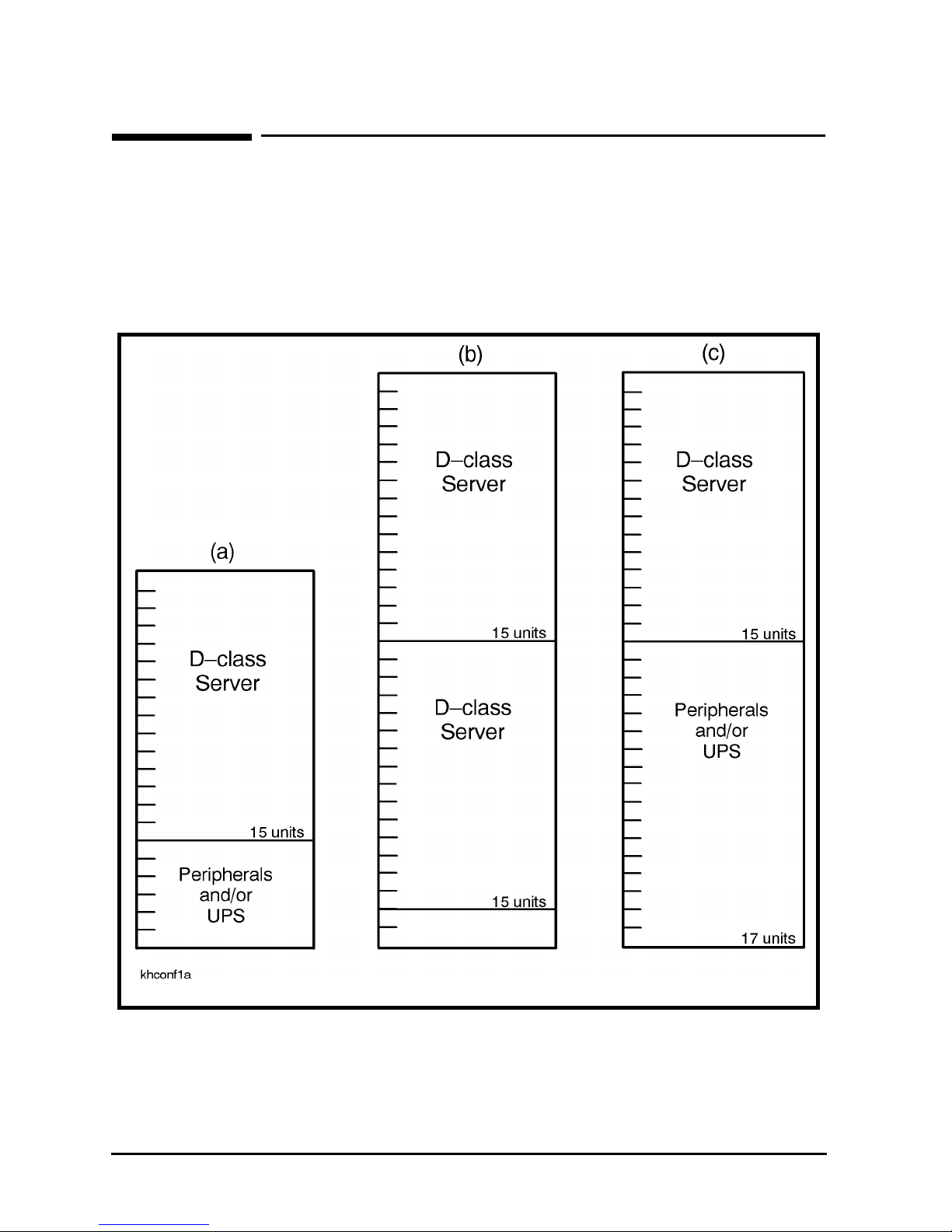
Cabinet Configurations
Although the cabinets are designed to accommodate a variety of components mounted in
just about any configuration, there are some basic rules that apply to mounting a computer
system. These rules allow for weight distribution, accessibility of the components, and
cable management inside the rack-mount cabinet. Figure 1-1shows some example
configurations.
Figure 1-1 Cabinet Configuration Examples
1-2 Chapter 1
Page 9

Required Tools
Required Tools
Before beginning the installation process, make sure you have the necessary tools.
1. Standard hand tools (including Torx-drive set and voltmeter).
2. Flat-blade screwdriver, 3/16-inch by 9 inches long.
3. Open-ended 9/16-inch wrench.
Introduction
Chapter 1 1-3
Page 10

Introduction
Required Tools
1-4 Chapter 1
Page 11
Site Requirements
2 Site Requirements
This chapter describes the site requirements for the installation of an HP A1896A or HP
A1897A cabinet. There is no HP site preparation required for the rack-mount cabinets.
There are some customer site preparation requirements. The customer is responsible for
having the proper type and amount of electrical outlets at the cabinet site. The customer
must also be aware of any system site requirements that the computer in the cabinet may
have. Be sure to check all site requirements before installing any equipment. Refer to
Table 2-1 for the cabinet physical specifications, and Table 2-2 for the cabinet electrical
requirements. T able 2-1 shows the types of receptacles that are needed to match the power
cords for specific cabinet power configurations.
NOTE There are no special environmental site requirements for the HP A1896A or
HP A1897A cabinets, or the computer systems contained in them.
Table 2-1 Physical Specifications
Cabinet specifications
All Models Width: 600 mm (23.6 in)
Depth: 905 mm (35.6 in)
Cooling and access space: 610 mm (24 in), front and rear
A1897A Height: 1.6 meter (63.8 inches)
A1896A Height: 1.1 meter (44.3 inches)
Table 2-2 Power Requirements
Cabinet PDU V/A Plug Type Receptacle Type
A1896A
(1.1 meter)
A1897A
(1.6 meter)
US 100-129V/50/60HZ, 16A max NEMA 5-20P NEMA 5-15 6
US 208-240V/50/60Hz, 16A max NEMA L6-20P NEMA L6-20R 10
Europe 230V/50/60Hz, 16A max Cable no plug Country dependent 10
US 208-240V/50/60Hz,16A max NEMA L6-20P NEMA L6-20R 10
Europe 230V/50/60Hz,16A max Cable no plug Country dependent 10
# IEC 320
Outlets
Refer to Figure 2-1 for the type of receptacle required to accommodate the cabinet power
cords.
Chapter 2 2-1
Page 12

Site Requirements
NOTE The cabinets that are sold in Europe are shipped without a power plug on the
end of the PDU cable. It is the responsibility of the customer to supply the
correct plug and receptacle for the particular country and electrical code, or
have the power cord wired to the power outlet.
Figure 2-1 Receptacle Types
CAUTION Ensure external power connection matches voltage settings of all products in
this cabinet.
2-2 Chapter 2
Page 13

Unpacking and Installation
3 Unpacking and Installation
This chapter describes how to unpack the A1896A or A1897A cabinet assembly. Both
cabinets are shipped on a pallet. The instructions for unpacking are the same for both the
A1896A and A1897A cabinet.
It is the customer's responsibility to inspect the shipping package for shipping damage.
It is the Hewlett-Packard Customer Engineer’s responsibility to remove the cabinet
assembly from the shipping pallet.
NOTE Do not discard or destroy the shipping container or the packaging material. If
it becomes necessary to repackage the cabinet, these items will be needed. HP
also suggests that you keep this manual, in case you later have to repackage
the cabinet for shipment.
Chapter 3 3-1
Page 14
Unpacking and Installation
Unpacking the Cabinet Assembly
Unpacking the Cabinet Assembly
All cabinet types are packaged the same way. Be sure to read the unpacking instructions
before proceeding.
WARNING A fully configured 1.6 meter cabinet (A1897A) can weigh up to
approximately 362.8 kg (800 lbs). Be very careful when unpacking the
cabinet.
To unpack an A series cabinet, perform the following steps:
1. Cut the plastic polystrap bands around the shipping container.
WARNING Wear protective glasses while cutting the plastic bands around the
shipping container. These bands are under tension. When cut, they
can spring back and cause serious eye injury.
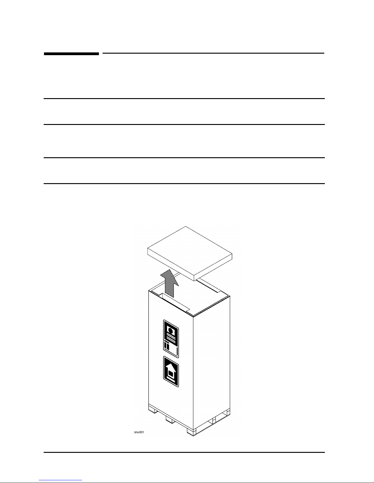
2. Lift the cardboard top cap off of the shipping box. See Figure 3-1.
Figure 3-1 Removing the Cardboard Container
3-2 Chapter 3
Page 15

Unpacking and Installation
Unpacking the Cabinet Assembly
3. Remove the clam shell box from the pallet.
4. Remove the ramp and packing material (1) from the top of the cabinet. See Figure 3-2.
Figure 3-2 Removing the Ramp and Packing Material
5. Remove the shrink wrap (2) from around the cabinet. This also holds the bezel
protective packing (3) on the front corners of the cabinet. Remove the bezel corner
packing (3). See Figure 3-2.
Chapter 3 3-3
Page 16

Unpacking and Installation
Unpacking the Cabinet Assembly
6. Carefully open the rear door (1). Remove the screw holding the rear door support (2) in
place and pull the block out. See Figure 3-3. Then close the rear door.
7. Remove the two (one on each side) shipping clamps from the bottom of the frame. They
are bolted to the pallet, remove the bolt (1) and then remove the clamp (2). See Figure
3-3.
Figure 3-3 Removing Shipping Clamp
8. Remove the pallet shipping block (2) from the rear of the pallet. Remove the two bolts
(1), one on each corner, and pull the block (2) out from under the cabinet. See Figure 3-4.
3-4 Chapter 3
Page 17

Figure 3-4 Removing the Shipping Block
Unpacking and Installation
Unpacking the Cabinet Assembly
9. Position the ramp so that the block of wood under the ramp locks into the edge of the
pallet with the strip of wood forming a lip. This holds the ramp in place while the
cabinet is moved across the pallet and down the ramp. See Figure 3-4.
10.Raise the cabinet leveling feet to their highest position.
WARNING Make sure that the leveling feet on the cabinet are raised before you
roll the cabinet down the ramp. If the leveling feet are not raised,
they can catch on the ramp and cause the cabinet to tip over.
11.Carefully roll the cabinet (3) down the ramp, as shown in Figure 3-4.
Chapter 3 3-5
Page 18

Unpacking and Installation
Cabinet Inspection
Cabinet Inspection
Once the cabinet is off the shipping pallet, and before it is placed in the installation site,
inspect the internal and external condition of the cabinet.
Exterior:
Check the cabinet exterior for signs of shipping damage:
1. Look at the top and sides for dents, warpage, or scratches.
2. Check the front bezels for alignment, scratches, and that they open and close normally.
3. Check any filler panels on the front of the cabinet, for proper fit.
4. Check the forehead assembly for any signs of damage.
5. Check the rear door for dents, scratches , proper fit, and operation. Also visually inspect
the fit of the door when it is closed.
Interior: Open the rear door and inspect the inside of the cabinet.
1. Inspect all cables, make sure they are secure.
2. Inspect all rails for signs of damage.
3. Check all mounting screws for tightness.
4. Check all components for signs of shifting during shipment or any signs of damage.
If any damage is found, follow the claims procedures described in Chapter 1. Some damage
may be repaired by replacing a damaged part, if that part is replaceable. Refer to Chapter
5 for a list of field replaceable parts for the cabinet. For internal component damage, refer
to the Service Manual for replaceable parts and procedures.
If extensive damage is found, it may be necessary to return the entire cabinet to HP. Refer
to the Repacking instructions listed in this chapter.
Cabinet Installation
The installation of the pre-loaded cabinets consist of the following steps:
1. Move the cabinet to installation site.
2. Lower the leveling feet. (This will prevent excessive wear on the casters.)
CAUTION It is strongly urged that the cabinet stabilizers also be extended as an
additional safeguard against overturning the cabinet during installation. The
stabilizer is an extendable slide located at the bottom front of the cabinet.
3. Connect the system console to the server.
3-6 Chapter 3
Page 19

Unpacking and Installation
PowerTrust UPS Option
4. Connect all user terminals to the server.
5. Connect all system peripherals to the server.
NOTE Attaching cables while the rails are extended fully forward will ensure
sufficient slack for later maintenance.
6. Connect the cabinet power cord to the appropriate wall outlet.
NOTE If the cabinet being installed contains a PowerTrust UPS option, perform the
steps under PowerTrust UPS Option.
7. Be sure all peripherals outside the cabinet are connected to wall outlets.
The cabinet/server system assembly is now ready for the power up process. Refer to
Chapter 4 for operating instructions.
PowerTrust UPS Option
Unpack the PowerTrust UPS and read all the installation information in the PowerTrust
System Guide part number 5961-8383. Once all the procedures listed in the UPS guide are
complete, perform the following steps to complete the UPS installation with the cabinet.
1. Position the UPS next to the cabinet on the floor.
2. Remove the jumper cord from the SPU to the PDU inside the cabinet.
3. Install one of the convenience cords (output cord) that came with the UPS into the AC
receptacle in the back of the SPU.
4. Place the other end of that cord into one of the Output outlets in the back of the UPS.
5. The other convenience cord is connected between the UPS and the system console.
6. Locate the appropriate input line cord for the UPS in the supplemental package
shipped with the UPS.
7. Plug the UPS into the appropriate wall outlet.
8. The system should now be ready for power up.
Repackaging the Cabinet for Shipment
Use the original packing material to repackage the cabinet for shipment. If the packing
material is not available, contact your local Hewlett-Packard Sales and Support Office
regarding shipment.
Chapter 3 3-7
Page 20

Unpacking and Installation
Repackaging the Cabinet for Shipment
Before shipment, place a tag on the container (or equipment) to identify the owner and the
service to be performed. Include the equipment model number and the full serial number,
if applicable. The label showing the model number and the full serial number is located on
the outside of the rear door.
Due to the weight of a fully loaded cabinet, it may require two people to push the cabinet
up the ramp onto the pallet.
WARNING Repackaging a loaded cabinet can be hazardous. This is due to the
weight of the loaded cabinet. Use caution when moving the cabinet
and positioning the cabinet on the pallet. Check the condition of the
loading/unloading ramp before use. If the ramp appears damaged,
DO NOT attempt to push the loaded cabinet up the ramp onto the
pallet. Contact your local Hewlett-Packard Sales and Support Office
regarding shipment.
To repackage the cabinet, follow the repacking checklist and refer to the unpacking
instructions for detail.
Repacking Checklist:
1. Assemble the HP packing materials that came with the cabinet.
2. Connect the loading ramp to the pallet.
3. Raise the cabinet levelers before moving the cabinet.
4. Push the cabinet up the ramp onto the pallet. Be sure to position the cabinet so the
front goes up the ramp first.
5. Secure the cabinet to the pallet with the shipping clamps, shipping block, and rear door
support.
6. Place the anti-static bag over the cabinet.
7. Place bezel support packing on the front corners of the cabinet. Secure it with some sort
of wrap.
8. Place the top cap packing material and loading/unloading ramp on top of the cabinet.
9. Wrap the clam shell box around the cabinet.
10. Put the box top on the box and secure the assembly to the pallet.
Be sure to follow the labeling instructions mentioned earlier. The cabinet is now ready for
shipment.
3-8 Chapter 3
Page 21

Cabinet Operation
Turning On the Computer System (Without UPS)
4 Cabinet Operation
Once you have the computer system installed in the rack-mount cabinet and all the
peripherals connected, you are ready to turn on the system. The power up sequence for the
computer in the cabinet is controlled by the ON/OFF switch on the cabinet, unless you
have installed a PowerTrust UPS.
Turning On the Computer System (Without UPS)
When turning on the computer in the cabinet, remember that includes all the components
mounted in the cabinet turn on at the same time. The basic steps for the power up
sequence are listed below, refer to the documentation that comes with the computer for
specific details concerning the operating system software for your computer.
CAUTION Ensure external power connection matches voltage setting of all products in
this cabinet.
1. Turn on all the external equipment connected to the computer first.
2. Check all READY or ONLINE indicators on the external equipment to be sure that they
are powered up and ready.
NOTE If any of the external equipment has been OFF due to environmental
problems such as heating or air conditioning failure, or outside storage
conditions (such as a loading dock), allow approximately 30 minutes for the
temperature of the equipment to stabilize before turning on the computer.
3. Be sure that all the cabinet-mounted component ON/OFF switches are in the ON
position.
4. When all external equipment indicate READY or ONLINE, put the cabinet ON/OFF
switch in the ON position. All components mounted in the cabinet are going to power up
at the same time.
Chapter 4 4-1
Page 22

Cabinet Operation
Turning On the Computer System (with UPS)
Turning On the Computer System (with UPS)
When turning on the cabinet power, remember that all the components mounted in the
cabinet turn on at the same time, except the SPU. The basic steps for the power up
sequence are listed below.
1. Turn on all the external equipment connected to the computer.
2. Check all READY or ONLINE indicators on the external equipment to be sure that they
are powered up and ready.
NOTE If any of the external equipment has been OFF due to any environmental
problem, such as heating or air conditioning failure, or outside storage
conditions (such as a loading dock) allow approximately 30 minutes for the
temperature of the equipment to stabilize before turning on the computer.
3. Except for the SPU, put all the ON/OFF switches, of the components mounted in the
cabinet, in the ON position. Leave the SPU ON/OFF switch in the OFF position.
4. When all external equipment indicates READY or ONLINE, put the cabinet ON/OFF
switch in the ON position. All components mounted in the cabinet are going to power up
at the same time (except for the SPU).
5. Put the UPS Output switch in the ON (|) position. This applies power to the SPU and
console line cords.
6. Put the SPU and console switches in the ON position.
7. The computer system should now be powered up and executing the power-on selftests in
preparation for a normal bootup procedure.
Turning Off the Computer System (Without UPS)
The computer has no remote turn off sensor for AC power. If the cabinet switch is put in
the OFF position before turning off the computer switch, the computer senses that as an
AC power fail condition.
1. Put the computer power switch in the OFF position.
2. Put the cabinet power switch in the OFF position. This removes AC from all the
components mounted in the cabinet, including the computer.
3. At this point, other components in the cabinet can be turned off, if necessary.
4-2 Chapter 4
Page 23

Cabinet Operation
Turning Off the Computer System (With UPS)
Turning Off the Computer System (With UPS)
If the cabinet ON/OFF switch is put in the OFF position, all components connected to the
cabinet PDU will be turned off. This does not turn off the computer.
1. Put the computer power switch in the OFF position.
2. Put the console power switch in the OFF position.
3. Put the UPS Output switch in the OFF (O) position.
4. Put the cabinet power switch in the OFF position. This removes AC from all the
components mounted in the cabinet, except the computer.
5. At this point, other components in the cabinet can be turned off if necessary.
Chapter 4 4-3
Page 24

Cabinet Operation
Turning Off the Computer System (With UPS)
4-4 Chapter 4
Page 25

Removal and Replacement Procedures
5 Removal and Replacement Procedures
This chapter lists all the parts of the HP A1896A, and HP A1897A rack-mount cabinet
that can be replaced if damaged. It also provides the procedures for accomplishing the
replacement of a damaged part. Refer to Figure 5-1 for an exploded view of the cabinet and
Table 5-1 for a list of the cabinet parts that can be replaced if damaged.
The A1896A cabinet does not come with a fan assembly. Otherwise, the procedures for
parts removal and replacement are the same.
Refer to Figure 5-1 and Figure 5-2 while performing the procedures outlined in this
chapter.
Figure 5-1 Cabinet Exploded View Front
Chapter 5 5-1
Page 26

Removal and Replacement Procedures
Figure 5-2 Cabinet Exploded View Rear
5-2 Chapter 5
Page 27

Table 5-1 Rack-mount Cabinet Replaceable Parts
No. Part No. Description
1 C2786-60016 Rear door assembly, 1.6 meter
3110-0197 Lock
E3661-00010 Latch Catch
0403-0780 Door Bumper
3 C2786-00012 Rear hinge
4 C2786-60015 Vented top cap
5 C2785-60007 Non-vented top cap
6/7 C2786-60014 Side cover, 1.6 meter
8 C2786-60004 Forehead assembly (with On/Off Switch)
5181-8713 On/Off Switch 120V
Removal and Replacement Procedures
5181-8714 On/Off Switch 220V
9 C2786-00014 Base cover, 1.6 meter
11 C2786-60018 Rail assembly
C2786-00019 Rear Stop Bracket
12 C2786-60024 230V Fan assembly
3160-0378 230V Fan
13 C2786-60005 115V Fan assembly
3160-0228 115V Fan
14 E4456-63001 US 208-240V PDU, 1.6 meter
15 E4457-63001 INT’L 230V PDU, 1.6 meter
18 C2786-00021 PDU Support Bracket
19 1492-0159 Caster
0535-0096 Nut-Wiz, M8 x 1.25 (caster)
20 0403-0778 Leveler
21 C2786-60017 Ballast assembly
0590-0804 Nut- Tinnerman 10/32
1
2680-0278 Screw, T15 10/32 w/washer
2680-0281 Screw, T25 10/32
C2786-60001 1U Filler assembly
Chapter 5 5-3
Page 28

Removal and Replacement Procedures
Removal and Replacement Procedures
No. Part No. Description
8120-5470 Rack device Power cord, 20 inches
8120-1396 Rack device power cord, 30 inches
C2786-00036
1. Ballast assembly is not provided on all configurations
Removal and Replacement Procedures
The following procedures are for the HP Field Replaceable Units (FRUs) contained in the
HP A1896A or HP A1897A rack-mount cabinets.
Rear Door
Refer to Figure 5-1 while performing these procedures.
Rear Door Removal:
1. Remove the rear door of the cabinet by opening the door.
2. Disconnect the bonding wire from the door.
3. Grasp the rear door support and lift the door straight up and away from the cabinet.
Rear Door Replacement:
1. Hold the rear door by the support column, in an open position.
2. Align the door hinge pins over the cabinet hinge holes.
3. Lower the door onto the cabinet hinge.
4. Reconnect the bonding wire to the door.
Top Cap
Refer to Figure 5-1 while performing these procedures.
Top Cap Removal:
1. Turn the cabinet power switch off and unplug the cabinet power cord.
2. Open the rear door all the way.
3. Remove the two outside mounting screws at the top rear of the cabinet.
4. From the rear of the cabinet, pull the top cap toward the back a few inches.
5. Lift the top cap off the cabinet.
Top Cap Replacement:
5-4 Chapter 5
Page 29

Removal and Replacement Procedures
Removal and Replacement Procedures
1. From the rear of the cabinet, place the top cap between the side covers and slide it
forward until it stops.
2. Insert the two mounting screws at the top rear. Tighten the screws.
3. Close the rear door. Plug the cabinet power cord into the wall outlet and power up the
computer system.
Side Cover
Refer to Figure 5-1 while performing these procedures.
Side Cover Removal:
1. Remove the two mounting screws at the bottom of the cabinet.
2. On the right side cover, open the rear door and remove the two mounting screws on the
upper door hinge (that secure the hinge to the side panel).
3. Grasp the sides of the side cover (pulling the bottom of the panel away from the cabinet
offers a better grip), then lift up and away.
Side Cover Replacement:
1. Grasp the side cover by the left and right edges and align it with the cabinet at an angle
with the bottom out and the top toward the top of the cabinet.
2. Lower the side onto the top edge of the cabinet side so the top of the side cover hooks
onto the top of the cabinet.
3. With the side cover flush with the cabinet frame, insert the two mounting screws in the
bottom. Tighten the screws.
4. On the right side cover, insert the mounting screws through the upper door hinge into
the side panel and tighten screws.
Forehead Assembly
To remove the forehead assembly, the power has to be turned off and the top cap has to be
removed first. Refer to Figure 5-1 while performing these procedures.
Forehead Assembly Removal:
1. Turn the power off (refer to Chapter 4 for power off procedures).
2. Unplug the cabinet power cord.
3. Remove the top cap (refer to top cap removal).
4. Unplug the PDU harness from the back of the ON/OFF switch.
5. Remove the three mounting screws behind the forehead assembly.
6. Pull the forehead assembly away from the cabinet frame.
Forehead Assembly Replacement:
Chapter 5 5-5
Page 30

Removal and Replacement Procedures
Removal and Replacement Procedures
1. Align the forehead assembly at the top of the cabinet frame, so the three mounting
holes match the frame holes, and the mounting hooks on each side engage the mounting
slots.
2. Insert the three mounting screws through the frame into the forehead assembly.
Tighten the screws.
3. Attach the PDU harness to the ON/OFF switch lugs as indicated:
Red: switch terminal 1
Black: switch terminal 2
White: switch terminal 6
4. Replace the top cap (refer to top cap replacement).
5. Plug the cabinet power cord into the wall outlet.
Base Cover
Refer to Figure 5-1 while performing these procedures.
Base Cover Removal:
1. Remove the mounting screw located on the top edge, center, of the base cover.
2. Pull the base cover away from the bottom of the cabinet.
Base Cover Replacement:
1. Align the base cover hooks on the bottom of the cabinet frame and roll the base cover
until the mounting holes in the cabinet and base cover align.
2. Insert the mounting screw. Tighten the screw.
Rear Door Hinge
Refer to Figure 5-1 while performing these procedures.
Rear Door Hinge Removal:
1. Remove the rear door (refer to rear door removal).
2. Remove the two mounting screws from the cabinet column (on the upper hinge, also
remove the two mounting screws in the side panel), and lift the door hinge away.
Rear Door Hinge Replacement:
1. Align door hinge with the pressed nuts in the rear cabinet column.
2. Insert the two mounting screws through the hinge into the column (on the upper hinge
insert the two mounting screws into the side panel). Tighten the screws.
5-6 Chapter 5
Page 31

Removal and Replacement Procedures
Removal and Replacement Procedures
Fan Assembly
Refer to Figure 5-3 and Figure 5-2 while performing these procedures.
NOTE The fan assembly is not present in the 1.1 meter cabinet.
Fan Assembly Removal:
1. Turn off the cabinet power. Refer to the power off procedures in Chapter 5.
2. Open the rear door.
3. disconnect the fan power cord from the PDU.
4. Remove the one mounting screw at the top rear cabinet frame bar.
5. Grasp the fan assembly from the bottom and pull toward the rear of the cabinet.
6. The fan assembly should release from the cabinet, and can be lowered out of the
cabinet.
Fan Assembly Replacement:
1. Raise the fan assembly into the rear cabinet frame opening.
2. Slide the fan assembly forward engaging the tabs on the fan assembly into the slots in
the cabinet frame.
3. Insert the mounting screw. Tighten the screw.
4. Connect the fan power cord from the fan assembly to the PDU.
5. The rear door can now be closed and the system powered up.
Figure 5-3 Fan Assembly
Chapter 5 5-7
Page 32

Removal and Replacement Procedures
Removal and Replacement Procedures
Fan
Refer to Figure 5-4 while performing these procedures.
Fan Removal:
1. Remove the fan assembly (refer to fan assembly removal).
2. Remove the power cable connectors from the fan.
3. Remove the two mounting screws and nuts holding the fan to the fan tray.
4. The fan bracket stays with the fan tray.
Fan Replacement:
1. Position the fan over the fan bracket/tray mounting holes so that the power lugs are at
the rear of the fan tray, and on the right side of the fan (as viewed from the back of the
assembly). Also verify the air flow arrow points up.
2. Insert the mounting screws up through the bottom of the fan tray/bracket and fan.
3. Attach mounting nuts/washers on the mounting screw. Tighten screws and nuts.
4. Attach power cord lugs to spades on the fan (polarity does not matter).
5. Replace fan assembly (refer to fan assembly replacement).
Figure 5-4 Fan Diagram
5-8 Chapter 5
Page 33

Removal and Replacement Procedures
Removal and Replacement Procedures
PDU
Refer to Figure 5-2 while performing these procedures.
PDU Removal:
1. Turn OFF the power switch on the front of the cabinet.
2. Unplug the cabinet power cord from the wall outlet.
3. Remove the top cap (refer to top cap removal).
4. Unplug the PDU harness from the back of the ON/OFF switch.
5. Unclip the PDU harness from the cable clamps on the cabinet frame top and pull the
PDU harness down through the top frame.
6. Remove all component power cords from the PDU.
7. Remove the four (two on each bracket) mounting screws from the PDU mounting
brackets that attach to the frame columns.
8. Lift the PDU up to disengage the PDU mounting bracket hooks from the frame column.
9. Pull the PDU out of the cabinet.
NOTE The PDU mounting brackets could be removed at this point if necessary.
PDU Replacement:
1. Align the PDU (with the brackets attached) on the right rear column of the cabinet
frame.
2. Insert the PDU bracket hooks into the column holes and lower the PDU until it rests on
the column.
3. Insert the PDU mounting screws through the brackets into the column with slip nuts
attached.
4. Route the PDU harness up through the top of the cabinet and through the cable clamps.
5. Plug the PDU harness onto the ON/OFF switch.
6. Replace the top cap (refer to top cap replacement).
7. Reconnect all the cabinet components to the PDU.
8. Plug the power cord into the wall outlet.
9. The cabinet and computer are ready to be powered up.
Cabinet Leveler or Caster
Refer to Figure 5-1 while performing these procedures.
Leveler or Caster Removal:
1. Turn Off the cabinet power switch.
Chapter 5 5-9
Page 34

Removal and Replacement Procedures
Removal and Replacement Procedures
2. Unplug the cabinet power cord from the wall outlet.
3. Carefully move the cabinet to an area with enough room to allow the cabinet to be laid
on its side.
4. Remove all computer components mounted in the cabinet.
5. Carefully lay the cabinet over on one of its sides.
6. Unscrew the desired leveler. Or, remove the desired caster by removing four mounting
nuts and pulling the caster off.
Leveler or Caster Replacement:
1. With the cabinet still on its side, screw in the leveler. Or, place the caster over the four
mounting studs, and attach the four mounting nuts. Tighten the nuts.
2. Carefully lift the cabinet back up to an upright position.
3. Install all computer components that were removed previously.
4. Carefully move the cabinet to its install site.
5. Plug the cabinet power cord into the wall outlet.
6. The cabinet is now ready for operation.
Lock and Latch
The lock and latch are located in the rear door.
Lock and Latch Removal:
1. Open the rear door.
2. Grasp the bracket supporting the lock and latch mechanism.
3. Remove the screw and star washer in the center of the bracket. The bracket will slide
off, and the lock and latch mechanism will slide out from the rear door.
4. Carefully note the position of the two screws attaching the latch catch to the cabinet
frame (the middle holes in segment 7 and 8 along the right rear cabinet frame). You will
need to mount the latch catch in the same position when replacing the mechanism.
5. Remove the two screws securing the latch catch to the cabinet frame.
Lock and Latch Replacement:
1. Align the two screw holes in the rear of the latch catch with the hole positions noted in
the removal process.
2. Attach the latch catch to the frame with two screws.
3. Slide the lock and latch mechanism through the hole in the outside of the rear door,
with the lock facing out.
4. Open the rear door and place the bracket over the latch mechanism, centering the hole
in the bracket over the hole in the lock mechanism.
5-10 Chapter 5
Page 35

Removal and Replacement Procedures
Removal and Replacement Procedures
5. Attach the bracket to the lock mechanism by inserting and tightening the screw and
star washer.
Door Bumper
The rear door bumpers (one top and one bottom) are self-adhesive rubber bumpers stuck to
the rear door. To remove, pry it off with a flat blade screwdriver. To put a bumper on, peel
off the adhesive cover, and press the bumper on the appropriate corner of the rear door.
Chapter 5 5-11
Page 36

Removal and Replacement Procedures
Removal and Replacement Procedures
5-12 Chapter 5
Page 37

System Servicing
Preparing the System for Servicing
6 System Servicing
This section provides servicing information for the rack-mounted Class D system.
Preparing the System for Servicing
WARNING It is strongly recommended that you fully extend the cabinet
stabilizer to reduce cabinet instability while servicing the system.
The cabinet may otherwise overturn and cause damage to the
equipment or possible injury.
1. Ensure that all power is disconnected from the system.
2. Remove the front bezel by grasping the detents on either side and pulling the bezel
toward you. Refer to Figure 6-1.
Figure 6-1 Removing the front bezel.
Chapter 6 6-1
Page 38

System Servicing
Preparing the System for Servicing
3. Remove the three screws on each side of the support brackets which attach the bracket
to the cabinet frame (refer to callout (1) in Figure 6-2).
4. Grasp the system just below the front center of the support brackets and pull toward
you, extending the system fully forward on its rails.
5. Using a T15 TORX screwdriver, remove the three screws in the pivot support bracket
(refer to callout (2) in Figure 6-2).
6. Swing the pivot support bracket around to the right and secure it by pressing it against
the fixed support bracket. The pivot support bracket will click into place.
Figure 6-2 Opening the pivot support bracket.
7. To access the interior of the system for service , refer to the System Service Manual, part
number A3262-90011.
6-2 Chapter 6
Page 39

System Servicing
Removing the System for Servicing
Removing the System for Servicing
If it is necessary to remove the system from the cabinet for further servicing, follow these
steps:
1. Remove any cables attached to the rear of the system.
NOTE Tag the cables, if necessary.
2. Remove the three screws shown by callout (1) in Figure 6-3. Remove the pivot support
bracket.
3. Remove the eight screws shown by callout (2) in Figure 6-3. Remove the fixed support
bracket.
Figure 6-3 Support Brackets
Chapter 6 6-3
Page 40

System Servicing
Removing the System for Servicing
4. Remove the three screws connecting the rear of the base plate assembly to the rear of
the component chassis (see Figure 6-4).
Figure 6-4 Positioning the System
5. Lift and remove the system from the base assembly.
CAUTION The system weighs as much as 100 lbs and may cause strain if lifted by one
person. Use two people to lift and remove the system.
6. Perform additional servicing as required.
7. Replace the system in the cabinet (see “System Replacement”).
6-4 Chapter 6
Page 41

System Servicing
Removing the System for Servicing
System Replacement
1. Extend the cabinet base assembly fully forward.
2. Position the system onto the base assembly as shown in Figure 6-4, aligning and setting
the system onto the guide pins (callout (1)) in the base plate assembly.
CAUTION The system weighs as much as 100 lbs and may cause strain if lifted by one
person. Use two people to lift and align the system.
3. Secure the fixed support bracket with the eight screws as shown in callout (2) of Figure
6-3.
4. Secure the pivot support bracket with the three screws as shown in callout (1) of Figure
6-3.
5. Replace the three screws along the rear of the assembly (refer to Figure 6-4).
6. Attach any new (or previously detached) cables to the system.
NOTE Attaching the cables while the rails are extended fully forward will ensure
sufficient slack for later maintenance.
CAUTION If the power supply was changed, ensure that the voltage setting of the switch
on the power supply matches the voltage of the cabinet PDU or UPS, if
present.
Chapter 6 6-5
Page 42

System Servicing
Rack Mount Assemblies
Rack Mount Assemblies
The following list shows the assemblies included in the rack mount assembly kit. Figure
6-5 displays the assembly pieces.
Part Number Description
A2362-60024 Base Assembly
A3262-60025 Fixed Support Assembly
A3262-60026 Pivot Support Assembly
A3262-60028 Slide Rail Assembly, Right
A3262-60029 Slide Rail Assembly, Left
A3262-60032 Bottom Bracket Assembly
A3262-00060 Top Bracket
A3262-00062 Short Ballast
A3262-60036 Rack Bezel Assembly
(Depicted in Figure 6-1)
Hardware and Miscellaneous
3020-0042 3/8-16 X 4 Bolt (2)
2190-0762 Flat Washer (2)
2190-0929 Lock Washer (2)
0590-0804 Tinnerman Nut (16)
2680-0278 10-32 Screw (14)
2680-0323 10-32 Screw (2)
0624-0719 6-32 Screw (14)
A3262-60043 Rack Door Kit
A3262-82008 Nameplate
A3262-81028 Label
A3262-90012 Cabinet Installation Guide
6-6 Chapter 6
Page 43

Figure 6-5 Rack Mount Kit Assemblies
System Servicing
Rack Mount Assemblies
Chapter 6 6-7
Page 44

System Servicing
Rack Mount Assemblies
6-8 Chapter 6
 Loading...