

Page 1

HP VISUALIZE Personal Workstation
User’s Guide
P- Class (A6034) and X-Class (A1280) Workstations
Printed in USA June 2000
Manufacturing Part Number: A1280-90002
Edition E0600
© Copyright 2000 Hewlett-Packard Company
Page 2

Notice
The information contained in this document is subject to change without
notice.
Hewlett-Packard makes no warranty of any kind with regard to this
material, including, but not limited to, the implied warranties of
merchantability and fitness for a particular purpose. Hewlett-Packard
shall not be liable for errors contained herein or for incidental or
consequential damages in connection with the furnishing, performance,
or use of this material.
Hewlett-Packard assumes no responsibility for the use or reliability of its
software on equipment that is not furnished by Hewlett-Packard.
This document contains proprietary information that is protected by
copyright. All rights reserved. No part of this document may be
photocopied, reproduced or translated to another language without the
prior written consent of Hewlett-Packard Company.
Trademark Acknowledgments
Adobe® Reader © 1987-1997 Adobe Systems Incorporated. All rights
reserved. Adobe and Acrobat are trademarks of Adobe Systems
Incorporated.
Microsoft® is a U.S. registered trademark of Microsoft Corporation.
WindowsTMis a trademark of Microsoft Corporation.Windows NT® is a
registered trademark of Microsoft Corporation.
Netscape® is a trademark of Netscape Communications Corporation.
PentiumTM is a trademark of Intel Corporation.
HP Printing Division:
Hewlett-Packard Company
3404 E. Harmony Road
Fort Collins, CO 80528-9599
USA
2
Page 3

Contents
1. Using Your Personal Workstation
X- and P-Class Product Description . . . . . . . . . . . . . . . . . . . . . . . . . . . . .22
X- and P-Class Workstation Physical Characteristics. . . . . . . . . . . . .24
Your Personal Workstation’s Hardware Control Panel . . . . . . . . . . . . . .25
HP MaxiLife and Its Display. . . . . . . . . . . . . . . . . . . . . . . . . . . . . . . . .25
Control Panel Lights . . . . . . . . . . . . . . . . . . . . . . . . . . . . . . . . . . . . . . .25
System Rear Panel Connectors. . . . . . . . . . . . . . . . . . . . . . . . . . . . . . . . .26
USB Connectors . . . . . . . . . . . . . . . . . . . . . . . . . . . . . . . . . . . . . . . . . . .27
Serial Connector. . . . . . . . . . . . . . . . . . . . . . . . . . . . . . . . . . . . . . . . . . .27
PS/2 Connectors . . . . . . . . . . . . . . . . . . . . . . . . . . . . . . . . . . . . . . . . . . .27
Audio Connectors . . . . . . . . . . . . . . . . . . . . . . . . . . . . . . . . . . . . . . . . . .28
Parallel IEEE 1284 I/O Connector . . . . . . . . . . . . . . . . . . . . . . . . . . . .28
LAN Connector. . . . . . . . . . . . . . . . . . . . . . . . . . . . . . . . . . . . . . . . . . . .29
Power Cord Connector . . . . . . . . . . . . . . . . . . . . . . . . . . . . . . . . . . . . . .29
Memory. . . . . . . . . . . . . . . . . . . . . . . . . . . . . . . . . . . . . . . . . . . . . . . . . . . .29
Monitors. . . . . . . . . . . . . . . . . . . . . . . . . . . . . . . . . . . . . . . . . . . . . . . . . . .29
Operating System Overview . . . . . . . . . . . . . . . . . . . . . . . . . . . . . . . . . . .30
Using Your Multimedia Keyboard . . . . . . . . . . . . . . . . . . . . . . . . . . . . . .31
Description of Softkeys on the Keyboard . . . . . . . . . . . . . . . . . . . . . . .31
Setting Up Your HP Multimedia Keyboard . . . . . . . . . . . . . . . . . . . . .34
The Euro Symbol . . . . . . . . . . . . . . . . . . . . . . . . . . . . . . . . . . . . . . . . . .37
HP Support Services . . . . . . . . . . . . . . . . . . . . . . . . . . . . . . . . . . . . . . .37
Using Your HP Mouse . . . . . . . . . . . . . . . . . . . . . . . . . . . . . . . . . . . . . . . .38
Starting and Stopping Your Personal Workstation . . . . . . . . . . . . . . . . .39
Starting Your Personal Workstation for the First Time. . . . . . . . . . . .39
Starting Your Personal Workstation. . . . . . . . . . . . . . . . . . . . . . . . . . .39
Initializing Your Software . . . . . . . . . . . . . . . . . . . . . . . . . . . . . . . . . . .40
Stopping Your Personal Workstation . . . . . . . . . . . . . . . . . . . . . . . . . .41
3
Page 4

Contents
Setting Your Password. . . . . . . . . . . . . . . . . . . . . . . . . . . . . . . . . . . . . . . 41
Setting the Administrator Password . . . . . . . . . . . . . . . . . . . . . . . . . . 41
Setting a User Password. . . . . . . . . . . . . . . . . . . . . . . . . . . . . . . . . . . . 42
Using Power Management. . . . . . . . . . . . . . . . . . . . . . . . . . . . . . . . . . . . 43
Connecting SCSI Accessories. . . . . . . . . . . . . . . . . . . . . . . . . . . . . . . . . . 44
Connecting an External SCSI Accessory. . . . . . . . . . . . . . . . . . . . . . . 45
Connecting Internal SCSI Accessories . . . . . . . . . . . . . . . . . . . . . . . . 48
Additional Information and Help . . . . . . . . . . . . . . . . . . . . . . . . . . . . . . 51
Recycling an Old HP Personal Workstation . . . . . . . . . . . . . . . . . . . . . . 52
2. Opening Your Personal Workstation and Installing Accessories
Supported HP Field Replaceable Units (FRUs) . . . . . . . . . . . . . . . . . . . 55
Removing and Replacing the Left-Side and Front Panels. . . . . . . . . . . 56
Removing the Left-Side Panel . . . . . . . . . . . . . . . . . . . . . . . . . . . . . . . 56
Removing the Front Panel . . . . . . . . . . . . . . . . . . . . . . . . . . . . . . . . . . 59
Replacing the Front Panel . . . . . . . . . . . . . . . . . . . . . . . . . . . . . . . . . . 64
Replacing the Left-Side Panel . . . . . . . . . . . . . . . . . . . . . . . . . . . . . . . 68
Installing and Removing Memory. . . . . . . . . . . . . . . . . . . . . . . . . . . . . . 71
Installing Additional Memory . . . . . . . . . . . . . . . . . . . . . . . . . . . . . . . 72
Removing Memory . . . . . . . . . . . . . . . . . . . . . . . . . . . . . . . . . . . . . . . . 75
Removable Media Devices . . . . . . . . . . . . . . . . . . . . . . . . . . . . . . . . . . . . 77
IDE and FDD Cable and Connector Information . . . . . . . . . . . . . . . . 77
Installing and Removing a CD Device. . . . . . . . . . . . . . . . . . . . . . . . . 79
Installing and Removing a Floppy Disk Drive . . . . . . . . . . . . . . . . . . 89
Hard Disk Drives . . . . . . . . . . . . . . . . . . . . . . . . . . . . . . . . . . . . . . . . . . . 95
Installing a Hard Disk Drive . . . . . . . . . . . . . . . . . . . . . . . . . . . . . . . . 95
Removing a Hard Disk Drive . . . . . . . . . . . . . . . . . . . . . . . . . . . . . . . 103
Installing and Removing Accessory Boards . . . . . . . . . . . . . . . . . . . . . 109
4
Page 5

Contents
AGP Pro Accessory Board Slot . . . . . . . . . . . . . . . . . . . . . . . . . . . . . .111
Installing I/O Cards . . . . . . . . . . . . . . . . . . . . . . . . . . . . . . . . . . . . . . .112
Removing I/O Cards. . . . . . . . . . . . . . . . . . . . . . . . . . . . . . . . . . . . . . .115
Installing and Removing a Processor. . . . . . . . . . . . . . . . . . . . . . . . . . .118
Removing the Processor. . . . . . . . . . . . . . . . . . . . . . . . . . . . . . . . . . . .119
Installing a Processor. . . . . . . . . . . . . . . . . . . . . . . . . . . . . . . . . . . . . .123
Installing and Removing a Voltage Regulator Module (VRM) . . . . . . .128
Removing a Voltage Regulator Module . . . . . . . . . . . . . . . . . . . . . . . .129
Installing a Voltage Regulator Module . . . . . . . . . . . . . . . . . . . . . . . .131
Installing Drivers and Utilities . . . . . . . . . . . . . . . . . . . . . . . . . . . . . . .134
3. Troubleshooting Your Personal Workstation
Solving Problems. . . . . . . . . . . . . . . . . . . . . . . . . . . . . . . . . . . . . . . . . . .136
HP Summary Screen . . . . . . . . . . . . . . . . . . . . . . . . . . . . . . . . . . . . . .136
HP Diagnostics . . . . . . . . . . . . . . . . . . . . . . . . . . . . . . . . . . . . . . . . . . .136
If Your Personal Workstation Does Not Start Properly. . . . . . . . . . . . .137
Display is Blank and There Are No Error Messages . . . . . . . . . . . . .137
If you are Unable to Change any Values in Setup . . . . . . . . . . . . . . .139
If a POST Error Message is Displayed . . . . . . . . . . . . . . . . . . . . . . . .140
If You Cannot Turn Off Your Personal Workstation . . . . . . . . . . . . . . .142
If Your Personal Workstation Has a Hardware Problem. . . . . . . . . . . .143
Display Does Not Work Properly. . . . . . . . . . . . . . . . . . . . . . . . . . . . .143
If Your Keyboard Does Not Work. . . . . . . . . . . . . . . . . . . . . . . . . . . . .144
If Your Mouse Does Not Work . . . . . . . . . . . . . . . . . . . . . . . . . . . . . . .144
If Your Local Printer Does Not Work . . . . . . . . . . . . . . . . . . . . . . . . .145
If the Floppy Disk Drive Does Not Work. . . . . . . . . . . . . . . . . . . . . . .146
If the Hard Disk Drive Does not Work . . . . . . . . . . . . . . . . . . . . . . . .146
If the CD-ROM Drive Has a Problem . . . . . . . . . . . . . . . . . . . . . . . . .147
If an Accessory Board Does not Work . . . . . . . . . . . . . . . . . . . . . . . . .149
5
Page 6

Contents
If Your Personal Workstation Has a Software Problem . . . . . . . . . . . . 150
If You Have Forgotten Your Password . . . . . . . . . . . . . . . . . . . . . . . . 150
If You Can’t Start the Setup Program . . . . . . . . . . . . . . . . . . . . . . . . 151
If the Date and Time Are Incorrect . . . . . . . . . . . . . . . . . . . . . . . . . . 151
If Your Application Software Does Not Work . . . . . . . . . . . . . . . . . . 151
If You Have a Network Problem. . . . . . . . . . . . . . . . . . . . . . . . . . . . . 152
If Your Personal Workstation Has an Audio Problem. . . . . . . . . . . . 152
Using HP MaxiLife to Diagnose Problems . . . . . . . . . . . . . . . . . . . . . . 153
Pre-Boot Checks . . . . . . . . . . . . . . . . . . . . . . . . . . . . . . . . . . . . . . . . . 154
POST Phase. . . . . . . . . . . . . . . . . . . . . . . . . . . . . . . . . . . . . . . . . . . . . 155
Operating System Boot Phase . . . . . . . . . . . . . . . . . . . . . . . . . . . . . . 155
Run-Time Errors. . . . . . . . . . . . . . . . . . . . . . . . . . . . . . . . . . . . . . . . . 156
Main Menu . . . . . . . . . . . . . . . . . . . . . . . . . . . . . . . . . . . . . . . . . . . . . 157
HP Hardware Diagnostics Utility. . . . . . . . . . . . . . . . . . . . . . . . . . . . . 162
Recovering Your Personal Workstation’s Operating System . . . . . . . . 164
4. Hewlett-Packard Support and Information Services
Introduction . . . . . . . . . . . . . . . . . . . . . . . . . . . . . . . . . . . . . . . . . . . . . . 166
Your HP-Authorized Reseller . . . . . . . . . . . . . . . . . . . . . . . . . . . . . . . . 167
Hewlett-Packard Information Services. . . . . . . . . . . . . . . . . . . . . . . . . 168
HP Forum on CompuServe. . . . . . . . . . . . . . . . . . . . . . . . . . . . . . . . . 168
HP Forum on America Online . . . . . . . . . . . . . . . . . . . . . . . . . . . . . . 169
HP World Wide Web Site . . . . . . . . . . . . . . . . . . . . . . . . . . . . . . . . . . 169
Ordering Drivers and BIOS on Diskette. . . . . . . . . . . . . . . . . . . . . . . . 170
HP Support Services . . . . . . . . . . . . . . . . . . . . . . . . . . . . . . . . . . . . . . . 172
Hewlett-Packard Telephone Support . . . . . . . . . . . . . . . . . . . . . . . . . . 173
Lifeline Telephone Support . . . . . . . . . . . . . . . . . . . . . . . . . . . . . . . . . . 175
Summary . . . . . . . . . . . . . . . . . . . . . . . . . . . . . . . . . . . . . . . . . . . . . . . . 176
6
Page 7

Contents
Hewlett-Packard Marketing Headquarters. . . . . . . . . . . . . . . . . . . . . .178
A. Regulatory Information and Warranty
Regulatory Information. . . . . . . . . . . . . . . . . . . . . . . . . . . . . . . . . . . . . .181
FCC (for USA only). . . . . . . . . . . . . . . . . . . . . . . . . . . . . . . . . . . . . . . .181
HP Hardware Warranty . . . . . . . . . . . . . . . . . . . . . . . . . . . . . . . . . . . . .184
HP Year 2000 Warranty. . . . . . . . . . . . . . . . . . . . . . . . . . . . . . . . . . . .184
Three Year Limited Hardware Warranty . . . . . . . . . . . . . . . . . . . . . .185
Limitation of Warranty . . . . . . . . . . . . . . . . . . . . . . . . . . . . . . . . . . . .186
Limitation of Liability and Remedies . . . . . . . . . . . . . . . . . . . . . . . . .186
Obtaining On-Site Warranty Service . . . . . . . . . . . . . . . . . . . . . . . . .187
Customer Responsibilities . . . . . . . . . . . . . . . . . . . . . . . . . . . . . . . . . .188
Obtaining Parts Warranty Service . . . . . . . . . . . . . . . . . . . . . . . . . . .188
HP Telephone Support Services . . . . . . . . . . . . . . . . . . . . . . . . . . . . .188
HP Software Product License Agreement and
Software Product Limited Warranty . . . . . . . . . . . . . . . . . . . . . . . . .189
HP Software Product License Agreement. . . . . . . . . . . . . . . . . . . . . .189
HP Software Product Limited Warranty. . . . . . . . . . . . . . . . . . . . . . .191
7
Page 8

Contents
8
Page 9

Figures
Figure 1-1. Front Panel Controls . . . . . . . . . . . . . . . . . . . . . . . . . . . . . . .25
Figure 1-2. System Unit Rear Panel Connectors. . . . . . . . . . . . . . . . . . .26
Figure 1-3. Audio Connectors . . . . . . . . . . . . . . . . . . . . . . . . . . . . . . . . . .28
Figure 1-4. HP’s Multimedia Keyboard . . . . . . . . . . . . . . . . . . . . . . . . . .34
Figure 1-5. Connecting HP’s Multimedia Keyboard . . . . . . . . . . . . . . . .34
Figure 1-6. Connecting the Microphone and Headset to the Keyboard .36
Figure 1-7. HP Three-Button Mouse . . . . . . . . . . . . . . . . . . . . . . . . . . . .38
Figure 1-8. Adaptec SCSI Card. . . . . . . . . . . . . . . . . . . . . . . . . . . . . . . . .44
Figure 1-9. Terminating the SCSI Accessory. . . . . . . . . . . . . . . . . . . . . .46
Figure 1-10. Connecting the Personal Workstation to the SCSI Accessory
46
Figure 1-11. Adaptec SCSI Card Internal Connectors . . . . . . . . . . . . . .48
Figure 2-1. Removing the Left-Side Panel Thumb Screws . . . . . . . . . . .57
Figure2-2.SlidingtheLeft-SidePaneltotheRearofthePersonalWorkstation
58
Figure 2-3. Removing the Left-Side Panel. . . . . . . . . . . . . . . . . . . . . . . .58
Figure 2-4. Lifting Up on the Top Section’s Retainer Tabs. . . . . . . . . . .60
Figure 2-5. View of the Top Section of the Front Panel Swung Outward. .
60
Figure 2-6. View of the Top Section’s Hinge Slots . . . . . . . . . . . . . . . . . .61
Figure 2-7. Lifting Up on the Bottom Section’s Retainer Tabs . . . . . . . .62
Figure2-8. View of the Bottom Section of the Front Panel Swung Outward
63
Figure 2-9. View of the Bottom Section’s Hinge Slots. . . . . . . . . . . . . . .63
Figure 2-10. View of the Bottom Section’s Hinge Slots. . . . . . . . . . . . . .64
9
Page 10

Figures
Figure 2-11. Connecting the Bottom Section to the Personal Workstation
65
Figure 2-12. Closing the Bottom Section . . . . . . . . . . . . . . . . . . . . . . . . 65
Figure 2-13. View of the Top Sections Hinge Slots. . . . . . . . . . . . . . . . . 66
Figure 2-14. Connecting the Top Section to the Personal Workstation. 67
Figure 2-15. Closing the Top Section. . . . . . . . . . . . . . . . . . . . . . . . . . . . 67
Figure 2-16. Inside View of the Left-Side Panel. . . . . . . . . . . . . . . . . . . 68
Figure 2-17. Replacing the Left-Side Panel . . . . . . . . . . . . . . . . . . . . . . 69
Figure 2-18. Left-Side Panel Showing the Half-Inch Gap. . . . . . . . . . . 69
Figure 2-19. Sliding the Left-Side Panel into Place. . . . . . . . . . . . . . . . 70
Figure 2-20. Replacing the Left-Side Panel Thumb Screws . . . . . . . . . 70
Figure 2-21. Personal Workstation Memory Slots . . . . . . . . . . . . . . . . . 71
Figure 2-22. Preparing the Memory Slot Ejector Tabs . . . . . . . . . . . . . 73
Figure 2-23. Installed DIMM Card . . . . . . . . . . . . . . . . . . . . . . . . . . . . . 74
Figure 2-24. Keyed DIMM Card . . . . . . . . . . . . . . . . . . . . . . . . . . . . . . . 74
Figure 2-25. Pressing Downward on the Memory Slot Ejector Tabs. . . 75
Figure 2-26. Lifting the DIMM Card Out of the Personal Workstation 76
Figure 2-27. IDE Cable . . . . . . . . . . . . . . . . . . . . . . . . . . . . . . . . . . . . . . 77
Figure 2-28. FDD Cable. . . . . . . . . . . . . . . . . . . . . . . . . . . . . . . . . . . . . . 78
Figure 2-29. System Board Connectors for the IDE and FDD Cables . 78
Figure 2-30. Removing the Front Panel CD Drive Blank . . . . . . . . . . . 80
Figure 2-31. Removing the Metal Blank from the Accessory Chassis. . 81
Figure 2-32. Attaching the Guide Rail to the CD Drive. . . . . . . . . . . . . 82
Figure 2-33. Properly Installed Guide Rail. . . . . . . . . . . . . . . . . . . . . . . 82
10
Page 11

Figures
Figure 2-34. Install the CD Drive into the Top Shelf . . . . . . . . . . . . . . .83
Figure 2-35. Connect the CD Drive Audio Cable. . . . . . . . . . . . . . . . . . .83
Figure 2-36. Connect CD Drive IDE Cable . . . . . . . . . . . . . . . . . . . . . . .84
Figure 2-37. Connect the CD Drive Power Cable. . . . . . . . . . . . . . . . . . .84
Figure 2-38. Disconnect the CD Drive Power Cable . . . . . . . . . . . . . . . .85
Figure 2-39. Disconnect CD Drive IDE Cable . . . . . . . . . . . . . . . . . . . . .85
Figure 2-40. Disconnect the CD Drive Audio Cable . . . . . . . . . . . . . . . .86
Figure 2-41. Remove the CD Drive into the Top Shelf . . . . . . . . . . . . . .86
Figure 2-42. Removing the Front Panel CD Drive Blank . . . . . . . . . . . .87
Figure 2-43. Replacing the Metal Blank into the Accessory Chassis. . .88
Figure 2-44. Floppy Disk Drive and Guide Rails. . . . . . . . . . . . . . . . . . .90
Figure 2-45. Attaching the Guide Rails to the Floppy Disk Drive . . . . .90
Figure 2-46. Install the Floppy Disk Drive into Its Shelf . . . . . . . . . . . .91
Figure 2-47. Connect the Floppy Disk Drive Power Cable . . . . . . . . . . .91
Figure 2-48. Connect Floppy Disk Drive FDD Cable. . . . . . . . . . . . . . . .92
Figure 2-49. Disconnect the Floppy Disk Drive FDD Cable . . . . . . . . . .93
Figure 2-50. Disconnect Floppy Disk Drive Power Cable . . . . . . . . . . . .93
Figure 2-51. Remove the Floppy Disk Drive from Its Shelf . . . . . . . . . .94
Figure 2-52. Hard Disk Drive and Guide Rails . . . . . . . . . . . . . . . . . . . .96
Figure 2-53. Attaching the Guide Rails to the Hard Disk Drive . . . . . .96
Figure 2-54. Install the Hard Disk Drive into Its Shelf . . . . . . . . . . . . .97
Figure 2-55. Connect the Hard Disk Drive Interface Cable . . . . . . . . . .97
Figure 2-56. Connect Hard Disk Drive Power Cable. . . . . . . . . . . . . . . .98
11
Page 12

Figures
Figure 2-57. Installing the Hard Disk Drive in its Mounting Bracket . 99
Figure2-58.AttachingGuideRailsontheHardDiskDriveMountingBracket
99
Figure 2-59. Install the Hard Disk Drive into Its CD Drive Shelf . . . 100
Figure 2-60. Connect the Hard Disk Drive Interface Cable . . . . . . . . 101
Figure 2-61. Connect Hard Disk Drive Power Cable . . . . . . . . . . . . . . 101
Figure 2-62. Disconnect the Hard Disk Drive Interface Cable . . . . . . 103
Figure 2-63. Disconnect Hard Disk Drive Power Cable. . . . . . . . . . . . 104
Figure 2-64. Remove the Hard Disk Drive from Its Shelf . . . . . . . . . . 104
Figure 2-65. Disconnect the Hard Disk Drive Interface Cable . . . . . . 105
Figure 2-66. Disconnect Hard Disk Drive Power Cable. . . . . . . . . . . . 105
Figure 2-67. Remove the Hard Disk Drive From Its CD Drive Shelf . 106
Figure2-68.RemovingtheHardDiskDriveGuideRailsandMountingScrews
106
Figure 2-69. Removing the Hard Disk Drive from Its Mounting Bracket
107
Figure2-70.ReplacingtheHardDisk Drive Mounting BracketGuideRails
107
Figure 2-71. Install the Hard Disk Drive Mounting Bracket . . . . . . . 108
Figure 2-72. I/O Card Slots and their Capabilities . . . . . . . . . . . . . . . 109
Figure 2-73. Card Guides for the Full-Size I/O Cards . . . . . . . . . . . . . 110
Figure 2-74. HP Visualize fx AGP Connector that is Not Supported . 111
Figure 2-75. Removing the T-15 Torx Screw and Bulkhead . . . . . . . . 112
Figure 2-76. Installing the I/O Card . . . . . . . . . . . . . . . . . . . . . . . . . . . 113
Figure 2-77. Completing the I/O Card Installation . . . . . . . . . . . . . . . 114
12
Page 13

Figures
Figure 2-78. Removing the I/O Card’s T-15 Torx Screw . . . . . . . . . . . .115
Figure 2-79. Removing the I/O Card. . . . . . . . . . . . . . . . . . . . . . . . . . . .116
Figure 2-80. Replacing the Bulkhead Blank . . . . . . . . . . . . . . . . . . . . .116
Figure 2-81. Processor Connectors and Terminator . . . . . . . . . . . . . . .118
Figure 2-82. Disconnect the Power Cable for the Processor’s Fan . . . .120
Figure 2-83. Remove the Fan Mount from the Processor Connectors .121
Figure 2-84. Remove the Processor. . . . . . . . . . . . . . . . . . . . . . . . . . . . .122
Figure 2-85. Installing the Processor . . . . . . . . . . . . . . . . . . . . . . . . . . .124
Figure 2-86. Placing the Fan Mount Over the Processors. . . . . . . . . . .125
Figure 2-87. Installing the Processor Fan Mount . . . . . . . . . . . . . . . . .126
Figure 2-88. Connect the Power Cable for the Processor’s Fan. . . . . . .126
Figure 2-89. Voltage Regulator Module (VRM) Slots. . . . . . . . . . . . . . .128
Figure 2-90. Ejector Tabs in the Downward Position . . . . . . . . . . . . . .130
Figure 2-91. Removing the Voltage Regulator Module (VRM) . . . . . . .131
Figure 2-92. Ejector Tabs in the Downward Position . . . . . . . . . . . . . .132
Figure 2-93. Installing the Voltage Regulator Module (VRM) . . . . . . .133
Figure 2-94. Installed Voltage Regulator Module (VRM) . . . . . . . . . . .133
13
Page 14

Figures
14
Page 15

Tables
Table 1-1. X- and P-Class Features. . . . . . . . . . . . . . . . . . . . . . . . . . . . . .22
Table 1-2. X- and P-Class Characteristics . . . . . . . . . . . . . . . . . . . . . . . .24
Table 1-3. Audio Electrical Specifications . . . . . . . . . . . . . . . . . . . . . . . .28
Table 1-4. Low-Voltage Differential SCSI Cables . . . . . . . . . . . . . . . . . .47
Table 2-1. Supported HP Field Replaceable Units. . . . . . . . . . . . . . . . . .55
Table 3-1. Actions to Take and Where to Find Help . . . . . . . . . . . . . . .138
Table 3-2. Pre-Boot Messages. . . . . . . . . . . . . . . . . . . . . . . . . . . . . . . . .154
Table 3-3. POST Phase Message. . . . . . . . . . . . . . . . . . . . . . . . . . . . . . .155
Table 3-4. Operating System Boot Phase Message . . . . . . . . . . . . . . . .155
Table 3-5. Run-Time Error Messages. . . . . . . . . . . . . . . . . . . . . . . . . . .156
Table 3-6. System Info. Messages . . . . . . . . . . . . . . . . . . . . . . . . . . . . . .159
Table 3-7. Example of Boot Steps Message . . . . . . . . . . . . . . . . . . . . . .159
Table 3-8. Test Component Messages. . . . . . . . . . . . . . . . . . . . . . . . . . .160
Table 4-1. HP Information Services . . . . . . . . . . . . . . . . . . . . . . . . . . . .166
Table 4-2. CompuServe On-line Service Numbers. . . . . . . . . . . . . . . . .168
Table 4-3. Lifeline Telephone Support Numbers . . . . . . . . . . . . . . . . . .175
15
Page 16

Tables
16
Page 17

Preface
This owner’s guide describes how to use your HP VISUALIZE P-Class
(A6034) or X-Class (A1280) Personal Workstation.
It is intended for the Personal Workstation user who wants to:
• Set up the Workstation for the first time.
• Configure the Workstation.
• Troubleshoot problems on the Workstation.
• Add accessories to the Workstation.
• Find out where to get more information and support.
17
Page 18

Important Safety Information
WARNING If you have any doubt that you can lift the HP VISUALIZE Personal
Workstation or display safely, do not try to move it without help.
For your safety, always connect the equipment to a grounded
wall outlet. Always use a power cord with a properly grounded
plug, such as the one provided with this equipment, or one in
compliance with you national regulations. This HP VISUALIZE
Personal Workstation is disconnected from the power by
removing the power cord from the power outlet. This means the
Personal Workstation must be located close to a power outlet
that is easily accessible.
For your safety, never remove the HP VISUALIZE Personal
Workstation’s cover without first removing the power cord from
the power outlet, and any connection to the telecommunications
network. Always replace the cover on the Personal Workstation
before switching it on.
To avoid electric shocks, do not open the power supply. There
are no user-serviceable parts inside.
This HP VISUALIZE Personal Workstation is a class 1 laser
product. Do not attempt to make any adjustment to the laser
units.
Important Ergonomic Information
It is strongly recommended that you read the ergonomic information
before using your HP VISUALIZE Personal Workstation. If you are using
Windows NT, open the Start menu in the task bar and select Help. Then
double-click the help topic “Working in Comfort.”
18
Page 19

Installation Notice
Products designated in the applicable Hewlett-Packard price list as
customer-installable can be installed by computer-knowledgeable
customers who carefully read and follow the instructions provided.
Customers who elect to have the product installed by our field personnel
are charged the applicable field installation charge, as covered under the
standard terms and conditions. For more information, please contact
your local sales representative.
Revision History
The revision history for each edition of the manual is listed below:
Edition Revision History
E0600 First Printing
Problems, Questions, and Suggestions
If you have any problems or questions with our hardware, software, or
documentation, please contact either your HP Response Center or your
local HP representative. If you have access to a web browser, you can get
the latest software and hardware patches at the following URL:
http://www.hp.com/visualize/support
19
Page 20

Documentation Conventions
Unless otherwise noted in the text, this guide uses the following symbolic
conventions.
user-supplied values
screen display Information that the system displays,
Enter Keycaps are presented with a special keycap
Italic words or characters in syntax and
command descriptions represent values that
you must supply. Italics are also used in text
for emphasis.
commands that you must use literally, and path
names appear in this typeface.
font as shown in the left column. (In this
document, we refer to the Enter key. On your
keyboard, the key may be labeled either Enter
or Return.)
Electrostatic Discharge (ESD) Precautions
Electrostatic charges can damage the integrated circuits on printed
circuit boards. To prevent such damage from occurring, observe the
following precautions during board unpacking and installation:
• Stand on a static-free mat.
• Wear a static strap to ensure that any accumulated electrostatic
charge is discharged from your body to ground.
• Create a common ground for the equipment you are working on by
connecting the static-free mat, static strap, and peripheral units to
that piece of equipment.
• Keep uninstalled printed circuit boards in their protective antistatic
bags.
• Handle printed circuit boards by their edges, once you have removed
them from their protective antistatic bags.
20
Page 21

Using Your Personal Workstation
1 Using Your Personal
Workstation
Chapter 1 21
Page 22

Using Your Personal Workstation
X- and P-Class Product Description
HP Visualize Personal Workstations are offered in two configurations the X-Class (A1280) and the P-Class (A6034). The major difference
between these configurations is maximum memory availability. The
P-Class is upgradeable to 2 GBytes (SDRAM) and the X-Class is
upgradeable to 4 GBytes (SDRAM).
X- and P-Class Product Description
To gain a better understanding of the HP VISUALIZE Personal
Workstations, see Table 1-1. This table lists the Personal Workstation’s
key features.
Table 1-1 X- and P-Class Features
Feature: Description:
Processor (standard) Intel Pentium III with 256 KB cache memory
and 133 MHz FSB
Main memory (size) Upgradeable to 4 GBytes (SDRAM) - X-Class
Upgradeable to 2 GBytes (SDRAM) - P-Class
Video (AGP Pro slot) HP VISUALIZE fx graphics cards (with/without
Texture Module), ELSA GLoria II graphics card
and ELSA Synergy II graphics card
LAN Ethernet 10BT/100TX LAN on the system board
Audio Integrated 16-bit high fidelity with high-end
mixing capability and SigmaDelta converters
22 Chapter1
Page 23
Using Your Personal Workstation
X- and P-Class Product Description
Table 1-1 X- and P-Class Features
Feature: Description:
Rear connectors • PS/2 mouse
• PS/2 keyboard
• 25-pin parallel
• 9-pin serial
• Two USB connectors
• LINE IN jack (3.5 mm)
• LINE OUT jack (3.5 mm)
• MIC IN jack (3.5 mm)
• Headset jack (3.5 mm)
Disk drive shelves Seven mass storage shelves supporting:
• Two front-access, 3.5-inch bays
• Three front-access, 5.25 in. bays
• Two internal hard disk drive bays
System board connectors • One flexible disk drive connector
• Two IDE connectors (for up to four IDE
devices)
• One CD-ROM audio connector
• Internal speaker connector
• One external start connector
Accessory slots • One AGP Pro (Accelerated Graphics Port)
slot
• Three 32-bit, 33 MHz, 5V PCI slots
• Two 64-bit, 66 MHz, 3.3V PCI slots
Chapter 1 23
Page 24
Using Your Personal Workstation
X- and P-Class Product Description
X- and P-Class Workstation Physical Characteristics
Table 1-2 X- and P-Class Characteristics
Characteristics: Description:
Weight (excl. keyboard and display) 15.93 kilograms (35.11 pounds).
Dimensions 47.3 cm (max.) (D) by 20.9 cm (W)
by 48.3 cm (H)
(18.62 inches by 8.22 inches
by 19.02 inches).
Footprint
Storage temperature −40˚C to +70˚C (−40˚F to +158 ˚F).
Storage humidity 8% to 90% (relative).
Operating temperature +5˚C to +35˚C (+41˚F to +95˚F).
Operating humidity 15% to 80% (relative).
0.099 m2 (1.06 sq ft).
24 Chapter1
Page 25
Your Personal Workstation’s Hardware Control Panel
Your Personal Workstation’s Hardware
Control Panel
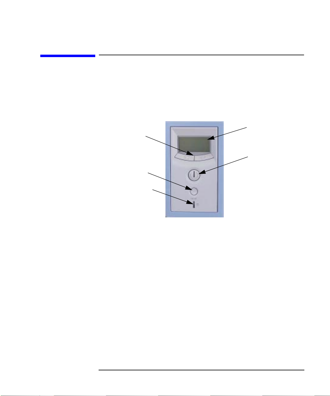
The hardware control panel is located on the front of your Personal
Workstation. See Figure 1-1.
Figure 1-1 Front Panel Controls
LCD Control
Buttons
Reset Button
Hard Disk Drive
Indicator Light
Using Your Personal Workstation
LCD
Power Button
and Indicator
Light
HP MaxiLife and Its Display
HP MaxiLife and its LCD helps you diagnose problems with your
Personal Workstation and provides system information you may need to
obtain support. Press one of the LCD control buttons to display the
menu.
Use ▲▼ to scroll through the menu items and ↵ to select the item
required. For more information on using the LCD, refer to the section
“Using HP MaxiLife to Diagnose Problems” in the chapter
“Troubleshooting Your Personal Workstation.”
Control Panel Lights
There are two lights on your Personal Workstation’s control panel. The
light in the middle of the on/off button glows when the system is on. The
other light is the hard disk drive indicator light, which glows when the
disk is active.
Chapter 1 25
Page 26
Using Your Personal Workstation
System Rear Panel Connectors
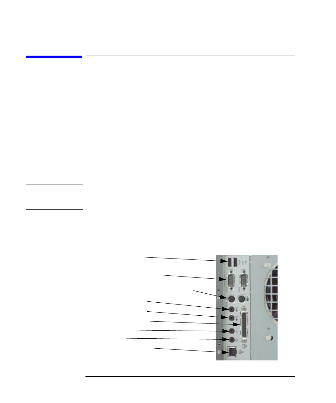
System Rear Panel Connectors
This section describes the following connectors on the system unit’s rear
panel:
• USB connectors
• Serial connectors
• PS/2 keyboard and mouse connectors
• Audio connectors (including headset and microphone)
• Parallel IEEE 1284 I/O connector
• LAN connector
• Power cord connector.
NOTE To maintain FCC/EMI compliance, verify that all cables are fully seated
and properly fastened.
Figure 1-2 shows the locations of the connectors on the system’s rear
panel.
Figure 1-2 System Unit Rear Panel Connectors
USB Connectors
Serial Port Connectors
Keyboard and Mouse Connectors
Line Input Jack
Line Output Jack
Parallel Connector
Microphone
Headset
LAN Connector
26 Chapter1
Page 27

Using Your Personal Workstation
System Rear Panel Connectors
USB Connectors
There are two Universal Serial Bus (USB) connectors located on the rear
panel of your Personal Workstation. These connectors support several
USB devices. Note that you should consult the documentation that
accompanies each device for specific information concerning its use.
For more information on the Universal Serial Bus, use your browser and
the following URL:
http://www.usb.org
Serial Connector
You can attach a variety of pointing devices (such as, a mouse or
trackball), or peripheral devices (such as, printer, plotters, and modems)
to the serial ports on this Personal Workstation. Consult the
documentation that accompanies each pointing or peripheral device for
specific information concerning its use.
PS/2 Connectors
There are two PS/2 connectors located on the rear panel of the Personal
Workstation. One PS/2 connector is labeled with a mouse and the other
connector is labeled with a keyboard.
Chapter 1 27
Page 28
Using Your Personal Workstation
System Rear Panel Connectors
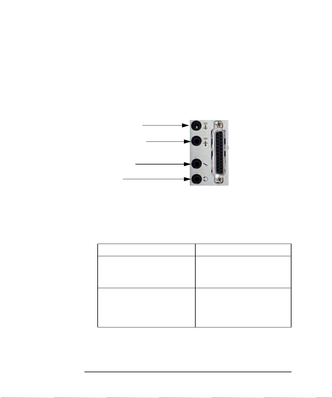
Audio Connectors
Your Personal Workstation has audio input and output capability
through external input and output connectors on the rear panel and
through an internal speaker. The rear panel contains the Line IN, Line
OUT, Mic IN, and Headset OUT connectors. See Figure 1-3.
Figure 1-3 Audio Connectors
Line Input Jack
Line Output Jack
Microphone
Headset
The audio connectors are standard stereo audio mini-jacks. For a
summary of the computer audio electrical specifications, see Table 1-3.
Note that the audio electrical specifications meet PC99 and AC97
requirements.
Table 1-3 Audio Electrical Specifications
Frequency Response 20 Hz to 20k Hz
Max Input Sensitivity/Impedance
Line in
Microphone
Max Output Level/Impedance
Line out
Headset
Speaker (internal)
2.0Vrms/10Kohms
100mVrms/47Kohm
1.5Vrms/40Kohms
1.0Vrms/32ohms
n.a.
Parallel IEEE 1284 I/O Connector
The 25-pin parallel I/O interface uses IEEE 1284 I/O interface protocols.
28 Chapter1
Page 29

Using Your Personal Workstation
Memory
LAN Connector
Your Personal Workstation has a built-in Twisted Pair (TP) connector for
the 802.3 (ETHERNET) or 10 BaseT/100 BaseT network. Your Personal
Workstation will automatically select the correct network setting.
Power Cord Connector
A 120V/240V AC power cord with three prong connectors for plugging
into the rear panel of the Personal Workstation and for the wall outlet.
Note that you can select between 120 volts AC and 240 volts AC using
the selector switch on back of the Personal Workstation.
Memory
The main memory for an HP VISUALIZE Personal Workstation can vary from a minimum of 256 MBytes and a maximum of 4 GBytes for the
X-Class and a 128 MByte minimum to a 2GByte maximum for the
P-Class. When you install the memory, you have to use matched pairs
(for example, two 128 MByte DIMM cards installed sequentially
according to the memory loading order). Note that there are four memory
slots for the X-Class and eight memory slots for the X-Class.
To learn how to install DIMM cards in your Personal Workstation, follow
the procedure in the section “Installing Memory” in the chapter
“Opening Your Personal Workstation and Installing Accessories.”
Monitors
You can use any PC monitor with your Personal Workstation.
Before using your monitor, you should become familiar with its controls,
connectors and indicators. For information on these controls and
indicators and on using your monitor, see the documentation that came
with the monitor.
Chapter 1 29
Page 30

Using Your Personal Workstation
Operating System Overview
Operating System Overview
Your Personal Workstation uses the Windows NT operating system. This
system comes pre-loaded on your system unit’s hard disk drive. When
you turn your system on, it will automatically boot-up into an NT
operating system.
If your system fails to boot-up, please read the chapter “Troubleshooting
Your Personal Workstation” before calling your HP support person.
Taking this action first could save you valuable time.
30 Chapter1
Page 31

Using Your Personal Workstation
Using Your Multimedia Keyboard
Using Your Multimedia Keyboard
The HP multimedia keyboard includes soft keys you can use to:
• Display and configure the actions assigned to keys.
• Perform one-touch shortcuts to start applications, open files, or open
sites on the World-Wide Web.
• Launch the Internet browser supplied with your system.
• Lock your Personal Workstation.
• Access HP TopTools and customer information.
• Mute or adjust the volume of the audio system.
This keyboard also includes audio and headset cables to plug into the
rear panel jacks of the Personal Workstation.
Description of Softkeys on the Keyboard
This section provides a description of softkeys you will find on your
multimedia keyboard.
Menu Key
Pressing the Menu soft key displays the soft key section of the HP
enhanced keyboard on your screen. Click any of the keys on the screen to
display the action assigned to an individual key or to change or assign an
action to a key. Shortcut keys are provided specifically for user-defined
actions.
Shortcut Keys
The Shortcut soft keys can be used to start an application, open a
document, or open a site on the Internet. Actions can be assigned to the
Shortcut keys by pressing the Menu key and clicking the key you want to
configure in the keyboard displayed on you screen.
Internet Key
This soft key is used to start the Netscape™ Communicator 4.0 browser
configured on the Personal Workstation (default setting). The MicroSoft®
Internet Explorer is also available.
Chapter 1 31
Page 32

Using Your Personal Workstation
Using Your Multimedia Keyboard
Lock Key
The action of the Lock key is configured by pressing the Menu Key, and
then clicking on Configure, the Extended Keys tab and the on-screen
Lock button. With HP Lock installed, the actions you can specify for the
Lock/Suspend key are:
• Launch screen saver
• Lock the front panel
HP TopTools
Pressing this soft key opens HP TopTools. This application helps you
manage and reduce overall ownership costs and provides advanced
Personal Workstation management tools that can, for example, be used
for remote BIOS updates and security management.
NOTE Before using HP TopToolsfor the first time, you must install it as follows:
• Select Programs from the Start menu.
• Select the submenu HP DMI.
• Select Setup from this menu.
The System Health window of the HP TopTools hardware monitoring
facility provides information on:
• Fan Control in the HP cooling system
• System Temperature for Personal Workstation components
• ECC Error Notification (only when ECC DIMMs are installed)
• Voltage Monitoring for components
Mute and Volume Keys
Pressing the Mute key mutes the audio, or restores the audio if it has
been muted. The Volume keys can be used to control the volume level.
For more information on controlling audio on your system, see the Using
Sound guide preloaded on your Personal Workstation.
32 Chapter1
Page 33

Using Your Personal Workstation
Using Your Multimedia Keyboard
Microphone and Headset Connectors
This multimedia keyboard has microphone and headset indicator lights
above the function keys, and just below these indicator lights on the
backside of the multimedia keyboard are plug-in jacks for the
microphone and headset. This feature allows you more flexibility for
locating your Personal Workstation other places than on top ofyour desk.
HP Customer Information
This soft key accesses HP Customer Information, which includes
information regarding:
• Product features
• Preloaded software on the system
• How to configure the HP enhanced keyboard
• How to configure the World-Wide Web browser
• HP support information
• Links to the HP Personal Workstation web site.
Chapter 1 33
Page 34

Using Your Personal Workstation
Using Your Multimedia Keyboard
Setting Up Your HP Multimedia Keyboard
This section provides a procedure that explains how to set up your
multimedia keyboard.
1. Shut down your Personal Workstation and connect the HP
multimedia keyboard to the Personal Workstation. See Figure 1-4
and Figure 1-5. The microphone and headset are not supplied with
the Personal Workstation.
Figure 1-4 HP’s Multimedia Keyboard
Figure 1-5 Connecting HP’s Multimedia Keyboard
Keyboard
Connector
Microphone
Connector
34 Chapter1
Mouse
Connector
Headset
Connector
Page 35

Using Your Personal Workstation
Using Your Multimedia Keyboard
NOTE When you connect the keyboard jack to the rear of the Personal
Workstation, the Personal Workstation’s internal speaker is deactivated.
You can then connect a headset or speakers to the rear of the multimedia
keyboard to get sound.
NOTE Toavoid discomfort from unexpected noise, always turn the volume down
before connecting headphones or speakers.
Listening to loud sounds for prolonged periods of time may permanently
damage your hearing. Before putting on your headset, place them
around your neck and turn the volume down. When you put on your
headset, slowly increase the volume until you find a comfortable
listening level, and leave the volume control at that position.
Chapter 1 35
Page 36

Using Your Personal Workstation
Using Your Multimedia Keyboard
2. Connect the microphone and headset to the rear of the multimedia
keyboard as shown in Figure 1-6. The microphone and headset are
one unit in this example. These devices can be separate units. Note
that speakers can be plugged into the headset jacket instead of a
headset.
Figure 1-6 Connecting the Microphone and Headset to the Keyboard
Microphone
Connector
Keyboard
Cable
Headset and
Speaker
Connector
NOTE Your Personal Workstation may have a CD or DVD drive. Even though
these drives may have a headset socket and a volume control, use the
keyboard sockets as described in this section. This will ensure that you
use all your Personal Workstation’s multimedia features.
36 Chapter1
Page 37

Using Your Personal Workstation
Using Your Multimedia Keyboard
The Euro Symbol
This section only applies if your keyboard comes with the Euro symbol
key (only available with certain language models).
Your keyboard’s Euro symbol key can only be used with Operating
Systems and applications that support this feature.
• Not all applications support the Euro symbol.
• Not all fonts contain the Euro character.
Windows NT 4.0 Euro Support
Windows NT 4.0 does not provide integrated support. For more
information on how to enable support of the Euro symbol, refer to
Microsoft’s web site at:
www.microsoft.com/windows/euro.asp
Configuring Your Keyboard for the Euro Symbol
To configure your keyboard, follow this procedure:
1. Select the Start button on the system status bar and select the menu
item Settings. While in the submenu, click on the item Control
Panel.
2. Double-click on the folder Keyboard in the “Folder Contents” frame
of the window.
3. Select the Language or Input Locales tab in the “Keyboard
Properties” window.
4. Click on Add and select the country that corresponds with your
keyboard, and click OK.
5. Click OK to exit the Control Panel.
HP Support Services
You can get help with solving problems with HP VISUALIZE accessories
from the following HP support web site:
www.hp.com/visualize/support
Chapter 1 37
Page 38

Using Your Personal Workstation
Using Your HP Mouse
Using Your HP Mouse
The mouse that is shipped with your system is an HP Three-Button
Mouse. See Figure 1-7.
Using your systems mouse software you can configure the mouse for a
left-handed or right-handed person. What this means is you can select
either the left or right mouse button to be the normal select and drag
button. In either case, the other outside button becomes the context
menu and special drag button. The middle button is used for pasting text
that has been saved on the system clipboard.
To configure your three-button mouse, follow these steps:
1. Click on the Start button.
2. Select the Settings menu, and then select the Control Panel
submenu.
3. Double-click on the Mouse icon and select the Buttons tab and
choose the appropriate settings.
Figure 1-7 HP Three-Button Mouse
Three-Button
Mouse
38 Chapter1
PS/2 Connector
Page 39

Using Your Personal Workstation
Starting and Stopping Your Personal Workstation
Starting and Stopping Your Personal
Workstation
Starting Your Personal Workstation for the First Time
If your Personal Workstation has preinstalled software, it is initialized
the first time you start the Personal Workstation. The software
initialization process takes a few minutes. This process sets up the
software in your language and sets up your software to use the hardware
installed in your computer (you can change the settings after the
software has been initialized).
Starting Your Personal Workstation
1. Before you start your Personal Workstation,turn on the display. If the
Personal Workstation is already turned on, save your data and exit
all programs, then restart the Personal Workstation.
2. Start your Personal Workstation in one of these ways:
• Press the power button on the front panel.
• Press the keyboard space bar. The keyboard power-on feature will
work only if Space-bar is enabled and you have a HP keyboard.
When you switch on the computer, it carries out the Power-On-Self-Test
(POST) while the HP VISUALIZE Workstation’s logo is displayed. If you
wish to view the POST details,press Esc to get the HP Summary Screen.
If there is an error in the POST, the error will automatically be
displayed.
Chapter 1 39
Page 40

Using Your Personal Workstation
Starting and Stopping Your Personal Workstation
Initializing Your Software
NOTE Do NOT switch OFF the Personal Workstation while the software is
being initialized—this could cause unexpected results.
To initialize your software:
1. Turn on the display first, and then turn on the Personal Workstation.
When the Personal Workstation is switched on, the HP VISUALIZE
Workstation’s logo is displayed. The Personal Workstation performs a
Power-On-Self-Test (POST). Press Esc if you want to view the POST
details in the HP Summary Screen.
If an error is detected during the Power-On-Self-Test, the Personal
Workstation will automatically display the error. You may be
prompted to press F2 to start the Setup program to correct the error.
2. The software initialization routine starts. It displays the software
license agreement, gives you an opportunity to read “Working in
Comfort” (ergonomic advice for computer users), and then asks
questions about the Personal Workstation. For example:
• The name of the person who will use the Personal Workstation
and your company name. (If necessary, the user name can be
modified later.)
• The current date and time.
• The type of printer (for example, HP LaserJet 5L). This is shown
on the front of the printer. You also need to enter the connection
used by the printer.
3. While the initialization program is running, you can complete the
Warranty Registration card that came with this manual.
4. When the initialization routine has finished, click OK and the
Personal Workstation will restart.
40 Chapter1
Page 41

Using Your Personal Workstation
Setting Your Password
Stopping Your Personal Workstation
To stop the Personal Workstation, make sure that you have exited all
programs and the operating system (if necessary), and then press the
On/Off button on the control panel.
Setting Your Password
You can set two passwords, the administrator (or supervisor) password
and the user password, to provide two levels of protection for your
Personal Workstation. You set both passwords using the Security menu
in the Setup program.
Setting the Administrator Password
Set the administrator password to protect the Personal Workstation’s
configuration in Setup. An administrator password can provide a
power-onpassword prompt thatprevents you Personal Workstation from
being started or used in your absence.
If you have set both an administrator password and user password, and
you enter the Setup program using the user password, you will be
restricted in your ability to change Setup items. If you enter the Setup
program with an administrator password, you will have no restrictions.
To set an administrator password:
1. Start the Setup program by pressing the F2 key during boot-up.
2. Select the Security menu.
3. Select the Supervisor Password submenu.
4. Choose the Set Supervisor Password setup item. You will be asked
to enter your password twice. When you see the Setup Notice
message, press any key to continue. Save your changes when you exit
the Setup program by selecting Exit, then Exit Saving Changes.
Toremove the password, follow the same procedure as to set a password.
You will be asked to enter the existing password first. Then, for the new
password, leave the password field blank and press Enter. To confirm
Chapter 1 41
Page 42

Using Your Personal Workstation
Setting Your Password
your choice, press Enter a second time.
Setting a User Password
A user password can only be set if an administrator password has
already been set using the Setup program.
Set a user password to provide a power-on password prompt. This will
prevent your Personal Workstation from being started or used in your
absence.
If you have set both an administrator password and user password, and
you enter the Setup program using the user password, you will be
restricted in your ability to change setup items. If you enter the Setup
program with and administrator password, you will have no restrictions.
To set a user password:
1. Start the Setup program by pressing the F2 key during boot-up.
2. Select the Security menu.
3. Select the User Password submenu.
4. Choose the Set User Password setup item. You will be asked to
enter your password twice. When you see the Confirmation
message, select Yes tocontinue. Once the password has been selected,
it is saved even if you choose Exit without Saving.
Toremove the password, follow the same procedure as to set a password.
You will be asked to enter the existing password first. Then, for the new
password, leave the password field blank and press Enter. To confirm
your choice, press Enter a second time.
NOTE If you forget your password, refer to the section “If You Have Forgotten
Your Password” in the chapter “Troubleshooting Your Personal
Workstation.”
42 Chapter1
Page 43

Using Your Personal Workstation
Using Power Management
Using Power Management
Power management enables you to reduce your Personal Workstation’s
overall power consumption by slowing down the Personal Workstation’s
activity when it is idle. To configure power management, refer to the
Power menu in the Setup program.
Refer to your operating system documentation for detailed information
about the capability of your operating system to implement power
management.
Chapter 1 43
Page 44

Using Your Personal Workstation
Connecting SCSI Accessories
Connecting SCSI Accessories
Your Personal Workstation is equipped with an Ultra 160/m SCSI card.
This section covers the connection of internal and external SCSI
accessories.
The Adaptec SCSI card is capable of connecting to Low-Voltage
Differential (LVD) SCSI devices (for example, Ultra2 and Ultra 160/m)
and Single-Ended (SE) SCSI devices (for example, Ultra SCSI, Fast
SCSI, SCSI-1, etc.). Examples of single ended devices include: DAT
drives, Scanners, and older hard disk drives.
Figure 1-8 Adaptec SCSI Card
Connector
Connector
Connector
Here is a description of connectors one through four as seen in Figure
1-8.
Connector 1 68-pin external connector for LVD SCSI devices
Connector 2 68-pin internal connector for LVD SCSI devices
Connector 3 68-pin internal connector for Wide SE SCSI devices
Connector 4 50-pin internal connector for Narrow SE SCSI devices
1
2
3
Connector
4
44 Chapter1
Page 45

Using Your Personal Workstation
Connecting SCSI Accessories
While SE SCSI devices will work when attached to connector 1 or 2, this
will limit all devices to single-ended mode. For example, this would
result in the Ultra 160/m hard disk drive performance being limited from
160 MB/second to 40 MB/second. Therefore, it is recommended that you
connect only LVD SCSI devices to connectors 1 and 2.
Connecting an External SCSI Accessory
The intended use of the external SCSI connector is to connect
Low-Voltage Differential SCSI devices to your Personal Workstation.
An external SCSI device is connected as follows:
1. Assign an unused SCSI address to the accessory. SCSI addresses
range from 0 to 15 for wide 16-bit SCSI devices. The SCSI address 0 is
reserved for the first SCSI hard disk drive and SCSI address 7 is
reserved for the SCSI controller (the default for narrow and wide
SCSI devices).
Refer to the manual provided with the SCSI accessory for
instructions on selecting a SCSI address.
NOTE You do not need to set a SCSI address for Plug-and-Play SCSI devices
(SCSI devices that support the SCAM protocol).
Chapter 1 45
Page 46

Using Your Personal Workstation
Connecting SCSI Accessories
2. Make sure the SCSI accessory is terminated correctly—either
internally or by a terminating resistor (refer to the manual provided
with the SCSI accessory). See Figure 1-9.
Figure 1-9 Terminating the SCSI Accessory
SCSI accessory is
properly terminated
3. Connect the SCSI accessory to your Personal Workstation’s external
68-pin SCSI connector with a shielded SCSI cable. See Figure 1-10.
Figure 1-10 Connecting the Personal Workstation to the SCSI Accessory
4. Refer to the manual provided with the SCSI accessory to learn how to
install any software that may be necessary for using it.
46 Chapter1
Page 47

Using Your Personal Workstation
Connecting SCSI Accessories
NOTE The total length of the external SCSI cable should not exceed 10 meters
(approximately 32 feet) and there must be at least eight inches of cable
separating each device.
Contact you dealer to order shielded HP SCSI cables to connect external
SCSI accessories.
CAUTION Low-voltage differential SCSI is very sensitive to noise, and therefore, all
cables on the SCSI bus must be exceptionally high quality cables.
Examples of these are given in Table 1-4.
Please make sure that any external hard disk enclosures are rated for
low-voltage differential SCSI use.
Table 1-4 Low-Voltage Differential SCSI Cables
Cable Number Cable Length Description
C2978A 0.5m
C2979A 1.5m
C2911B 1.0m
C2924B 2.5m
C2361A 1.0m
C2362A 2.5m
C2363A 10.0m
C2365A 5.0m
1. High Density Thumbscrew (HDTS)
2. Very High Density Cabled Interconnect (VHDCI)
Chapter 1 47
68-pin HDTS1 to 68-pin HDTS
68-pin VHDCI2 to 68-pin HDTS
Page 48

Using Your Personal Workstation
Connecting SCSI Accessories
Connecting Internal SCSI Accessories
There are three internal SCSI connectors located on the Adaptec SCSI
card. See Figure 1-11. Your Personal Workstation comes with a LVD
SCSI cable for connecting internal LVD SCSI devices. To connect
internally Wide SE and Narrow SE SCSI devices, you will need to
purchase a cable for them.
NOTE While SE SCSI devices will work when attached to the LVD SCSI
connector, this will limit all devices to single-ended mode.
To learn how to install you internal SCSI device, read the chapter
“Opening Your Personal Workstation and Installing Accessories.” For
additional installation information, read the subsequent sections.
Figure 1-11 Adaptec SCSI Card Internal Connectors
Wide (68-pin) LVD SCSI Connector
Wide (68-pin) SE SCSI Connector
Narrow (50-pin)
SE SCSI
Connector
48 Chapter1
Page 49

Using Your Personal Workstation
Connecting SCSI Accessories
Connecting LVD SCSI Accessories
The intended use for the internal LVD SCSI connector is to connect
internal Low-Voltage Differential SCSI devices to your Personal
Workstation.
An internal LVD SCSI devices is connected as follows:
1. Assign an unused SCSI address to the accessory. SCSI addresses
range from 0 to 15 for wide 16-bit SCSI devices. The SCSI address 0 is
reserved for the first SCSI hard disk drive and SCSI address 7 is
reserved for the SCSI controller (the default for narrow and wide
SCSI devices).
Refer to the manual provided with the SCSI accessory for
instructions on selecting a SCSI address.
2. Connect the SCSI accessory to your Personal Workstation’s internal
68-pin LVD SCSI connector with the SCSI cable shipped with your
system.
3. Refer to the manual that was provided with you SCSI accessory to
learn how to install any software that may be necessary for using it.
Chapter 1 49
Page 50

Using Your Personal Workstation
Connecting SCSI Accessories
Connecting SE SCSI Accessories
The intended use for the internal Wide SE SCSI and Narrow SE SCSI
connectors is to connect internal Wide and Narrow single-ended SCSI
devices to your Personal Workstation.
An internal Wide or Narrow single-ended SCSI device can be connected
as follows:
1. Assign an unused SCSI address to the accessory. SCSI addresses
range from 0 to 15 for wide 16-bit SCSI devices and 0 to 8 for narrow
8-bit SCSI devices. The SCSI address 0 is reserved for the first SCSI
hard disk drive and SCSI address 7 is reserved for the SCSI
controller (the default for narrow and wide SCSI devices).
Refer to the manual provided with the SCSI accessory for
instructions on selecting a SCSI address.
2. Connect the SCSI accessory to your Personal Workstation’s internal
68-pin wide SE SCSI connector or 50-pin narrow SE SCSI connector
with the SCSI cable you purchased.
3. Refer to the manual that was provided with you SCSI accessory to
learn how to install any software that may be necessary for using it.
50 Chapter1
Page 51

Using Your Personal Workstation
Additional Information and Help
Additional Information and Help
Additional information about your Personal Workstation is preloaded on
the Personal Workstation’s hard disk drive. This information includes:
• New features—what is new and special about your Personal
Workstation
• Working in comfort—guidance on ergonomics issues
• Using Sound—provides guidance on audio issues
• Network Administrator’s Guide—provides instructions on setting up
your Personal Workstation for a LAN connection
• Glossary.
Users of Windows NT 4.0 can access this information by opening the
Start menu in the task bar and selecting Programs>HPInfo.
Chapter 1 51
Page 52

Using Your Personal Workstation
Recycling an Old HP Personal Workstation
Recycling an Old HP Personal Workstation
HP has a strong commitment towards the environment. This HP
Personal Workstation has been designed to respect the environment as
much as possible.
HP can take an old computer back for recycling when it reaches the end
of its useful life.
In several countries, HP has a product take-back program. Collected
equipment is sent to one of HP’s recycling facilities in Europe or the
United States. As many parts as possible are reused, the remainder are
recycled. Special care is taken with batteries and other potentially toxic
substances, which are reduced to non-harmful components through a
special chemical process.
If you require more details about HP’s product take-back program,
contact your dealer or your nearest HP Sales Office.
52 Chapter1
Page 53

2 Opening Your Personal
Workstation and Installing
Accessories
This chapter explains how to open your Personal Workstation and install
accessories, such as extra memory, I/O boards and additional disk drives.
53
Page 54

Opening Your Personal Workstation and Installing Accessories
If you will be either installing or removing accessories from your
Personal Workstation, you will need to have the proper tools for these
tasks:
• A light-duty flat-blade screwdriver with a 150mm (6 inch) shaft. The
flat blade should be of the proper width to fit in the slot on a T-15 Torx
screw.
• A T-15 Torx screwdriver. Note that the screws these screwdrivers are
used on have a recessed slot for use with a flat-bladed screwdriver.
WARNING Always unplug the Personal Workstation power cord from the
electrical outlet or power source before opening the Personal
Workstation.
54 Chapter2
Page 55

Opening Your Personal Workstation and Installing Accessories
Supported HP Field Replaceable Units (FRUs)
Supported HP Field Replaceable Units (FRUs)
Table 2-1 provides you with a list of the supported hard disk drives, CD
drives, memory cards, floppy disk drives and I/O cards.
Table 2-1 Supported HP Field Replaceable Units
Type of FRU Description
Hard Disk Drive 18 GByte, 10 K rpm Ultra 160/m Wide Low-Voltage
Differential SCSI
9 GByte, 10 K rpm Ultra 160/m Wide Low-Voltage
Differential SCSI
CD Drive CD-ROM, ATAPI controller
DVD-ROM, ATAPI controller
CD-RW, ATAPI controller
Floppy disk Drive 1.44 MByte Floppy Disk Drive
Memory Cards 64 MByte DIMM (P-Class only)
128 MByte DIMM
256 MByte DIMM
512 MByte DIMM
I/O Cards Three 32-bit, 33 MHz, 5V PCI slots
Two 64 bit, 66 MHz, 3.3V PCI slots
One AGP Pro slot
Chapter 2 55
Page 56

Opening Your Personal Workstation and Installing Accessories
Removing and Replacing the Left-Side and Front Panels
Removing and Replacing the Left-Side and
Front Panels
This section explains how to remove your Personal Workstation’s
left-side panel and its front panel. This section also explains how to
replace the front and left-side panels of your Personal Workstation. Note
that it is important to be able to remove the left-side panel and front
panel in order to gain access to accessory shelves, memory slots, I/O slots,
and the system processor.
Removing the Left-Side Panel
The procedure in this section explains how to remove the left-side panel
of your Personal Workstation (use the Personal Workstation’s front panel
as the reference).
Top Section
of Front Panel
Left-Side Panel
Bottom Section
of Front Panel
56 Chapter2
Page 57

Opening Your Personal Workstation and Installing Accessories
Removing and Replacing the Left-Side and Front Panels
WARNING Turn the Personal Workstation off and unplug the power cord
before replacing or removing the left-side panel.
1. Remove the left-side panel’s two thumb screws. See Figure 2-1.
Figure 2-1 Removing the Left-Side Panel Thumb Screws
Thumb Screws
Chapter 2 57
Page 58

Opening Your Personal Workstation and Installing Accessories
Removing and Replacing the Left-Side and Front Panels
2. Slide the left-side panel toward the rear of the Personal Workstation
approximately 0.5 inches as shown in Figure 2-2.
Figure 2-2 Sliding the Left-Side Panel to the Rear of the Personal
Workstation
This gap is approximately
0.5 inches.
3. Remove the left-side panel by grasping the rear part of the panel as
shown in Figure 2-3 and pulling the panel outward. Next, lift the
panel up and away from the Personal Workstation, and place it where
its exterior surface cannot be damaged.
Figure 2-3 Removing the Left-Side Panel
58 Chapter2
Page 59

Opening Your Personal Workstation and Installing Accessories
Removing and Replacing the Left-Side and Front Panels
Removing the Front Panel
The front panel can only be removed after you have removed the left-side
panel. The front panel is divided into a top and bottom section. Removing
the top section of the front panel allows you access to the accessory
shelves (for example, CD drive and floppy disk drive), and removing the
bottom section allows you access to the control panel module.
NOTE The bottom section of the front panel can only be removed after the top
section of the front panel is removed.
Top Section Removal
The procedure in this section explains how to remove the top section of
the front panel. Removing the top section of the front panel gives you
access to the Personal Workstation’s accessory shelves. These shelves are
the 5.25 inch shelves (bay area for CD drives and hard disk drives) and
the 3.5 inch shelves (bay area for floppy disk drive and other floppy disk
size devices).
1. Remove the left-side panel as explained in the section “Removing the
Left-Side Panel” in this chapter.
Chapter 2 59
Page 60

Opening Your Personal Workstation and Installing Accessories
Removing and Replacing the Left-Side and Front Panels
2. Lift up on both retainer tabs of the top section of the front panel.
While holding the tabs, swing this section outward 15 degrees in the
direction of the arrow. See Figure 2-4.
Figure 2-4 Lifting Up on the Top Section’s Retainer Tabs
Retainer Tabs
for the Front
Panel Top
Section
View from
the top
Your front panel’s top section will look like the one in Figure 2-5 when
you have completed this step.
Figure 2-5 View of the Top Section of the Front Panel Swung Outward
Front Panel’s
Top Section
View from
the top
60 Chapter2
Front Panel’s
Top Section
Push
15˚
Page 61

Opening Your Personal Workstation and Installing Accessories
Removing and Replacing the Left-Side and Front Panels
3. Hold the top section of the front panel in one hand and push this
section in the direction of the “Push” arrow as shown in Figure 2-5.
This will release the top section’s hinge tabs from their hinge slots
and the top section will be freed from the system chassis. See Figure
2-6.
Figure 2-6 View of the Top Section’s Hinge Slots
Hinge Slots
Chapter 2 61
Page 62

Opening Your Personal Workstation and Installing Accessories
Removing and Replacing the Left-Side and Front Panels
Bottom Section Removal
The procedure in this section explains how to remove the bottom section
of the front panel. Removing the bottom section of the front panel gives
you access to the Personal Workstation’s control module.
1. Remove the left-side panel as explained in the section “Removing the
Left-Side Panel” in this chapter, and remove the top section of the
front panel as explained in the section “Top Section Removal” in this
chapter.
2. Lift up on both retainer tabs of the bottom section of the front panel.
While holding the tabs, swing this section outward 15 degrees in the
direction of the arrow. See Figure 2-7.
Figure 2-7 Lifting Up on the Bottom Section’s Retainer Tabs
View from
the top
15˚
Retainer Tabs
for the Front
Panel Bottom
Section
62 Chapter2
Page 63

Opening Your Personal Workstation and Installing Accessories
Removing and Replacing the Left-Side and Front Panels
Your front panel’s bottom section will look like the one in Figure 2-8
when you have completed this step.
Figure 2-8 View of the Bottom Section of the Front Panel Swung Outward
Front Panel’s
Bottom section
Front Panel’s
View from
the top
3. Hold the bottom section of the front panel in one hand and push this
section in the direction of the “Push” arrow as shown in Figure 2-8.
This will release the bottom section’s hinge tabs from their hinge slots
and the bottom section will be freed from the system chassis. See
Figure 2-9.
Bottom Section
Push
Figure 2-9 View of the Bottom Section’s Hinge Slots
Chapter 2 63
Hinge Slots
Page 64

Opening Your Personal Workstation and Installing Accessories
Removing and Replacing the Left-Side and Front Panels
Replacing the Front Panel
After you have completed your accessory installation or control module
repair, you will need to replace the front panel. This section explains how
to perform this task.
NOTE The bottom section of the front panel must be replaced before replacing
the top section. Also, note that the left-side panel must be off the
Personal Workstation before you can replace the front panel sections.
Bottom Section Replacement
The procedure in this section explains how to replace the bottom section
of the front panel.
1. Locate the bottom section hinge slots and tabs. See Figure 2-10.
Figure 2-10 View of the Bottom Section’s Hinge Slots
Hinge Slots
64 Chapter2
Page 65

Opening Your Personal Workstation and Installing Accessories
Removing and Replacing the Left-Side and Front Panels
2. Place the hinge tabs of the bottom section into the hinge slots. To
complete this step, hold the bottom section of the front panel at a 15
degree angle to the front of the Personal Workstation and pull in the
direction of the arrow. See Figure 2-11.
Figure 2-11 Connecting the Bottom Section to the Personal Workstation
View from
the top
3. Close the bottom section by pushing it inward in the direction of the
arrow. See Figure 2-12. The retainer tabs should snap into place.
Figure 2-12 Closing the Bottom Section
Retainer Tabs
for the Front
Panel Bottom
Section
15˚
Pull
View from
the top
15˚
Push
Chapter 2 65
Page 66

Opening Your Personal Workstation and Installing Accessories
Removing and Replacing the Left-Side and Front Panels
Top Section Replacement
The procedure in this section explains how to replace the top section of
the front panel.
1. Locate the top section hinge slots and tabs. See Figure 2-13. Note that
the bottom section of the front panel should already be installed.
Figure 2-13 View of the Top Sections Hinge Slots
Hinge Slots
66 Chapter2
Page 67

Opening Your Personal Workstation and Installing Accessories
Removing and Replacing the Left-Side and Front Panels
2. Place the hinge tabs of the top section into the hinge slots. To
complete this step, hold the top section of the front panel at a 15
degree angle to the front of the Personal Workstation and pull in the
direction of the arrow. See Figure 2-14.
Figure 2-14 Connecting the Top Section to the Personal Workstation
View from
the top
3. Close the top section by pushing it inward in the direction of the
arrow. See Figure 2-15. The retainer tabs should snap into place.
Figure 2-15 Closing the Top Section
Retainer Tabs
for the Front
Panel Top
Section
View from
the top
15˚
Pull
15˚
Push
Chapter 2 67
Page 68

Opening Your Personal Workstation and Installing Accessories
Removing and Replacing the Left-Side and Front Panels
Replacing the Left-Side Panel
This section explains how to replace the left-side panel of your Personal
Workstation. The inside view of this panel is shown in Figure 2-16 to
help you with the panel’s nomenclature.
Figure 2-16 Inside View of the Left-Side Panel
Panel Hook (there are four)
Lock Latch
Rear Edge of Panel
Left-Side Panel
Panel Guide
WARNING Turn the Personal Workstation off and unplug the power cord
before replacing or removing the left-side panel.
68 Chapter2
Page 69

Opening Your Personal Workstation and Installing Accessories
Removing and Replacing the Left-Side and Front Panels
To replace the left-side panel, follow this procedure:
1. Place the panel guide over the system’s inside-bottom edge, leaving a
half-inch gap between the front edge of the panel and the front of the
chassis. See Figure 2-17 and Figure 2-18.
Figure 2-17 Replacing the Left-Side Panel
Hook Slot (There are
four of them on this
edge. The four panel
hooks fit into these
slots.)
Panel Guide
System’s inside-bottom edge
Figure 2-18 Left-Side Panel Showing the Half-Inch Gap
Chapter 2 69
0.5 inch gap
Page 70

Opening Your Personal Workstation and Installing Accessories
Removing and Replacing the Left-Side and Front Panels
2. Locate the four hook slots on the top edge of the system and align
these slots with the four panel hooks on the left-side panel. Next,
push the left-side panel inward (in the direction of the arrow). See
Figure 2-19. Note that in some cases you might have to lift up slightly
on the panel to get the panel hooks to fit in the slots.
Figure 2-19 Sliding the Left-Side Panel into Place
3. Screw the left-side panel thumb screws in place to complete the
left-side panel replacement on the Personal Workstation. See Figure
2-20.
Gap is approx.
0.5 inches
Figure 2-20 Replacing the Left-Side Panel Thumb Screws
70 Chapter2
Thumb Screws
Page 71

Opening Your Personal Workstation and Installing Accessories
Installing and Removing Memory
Installing and Removing Memory
This section contains information on how to install and remove memory
(DIMM cards).
NOTE The memory must be loaded in pairs, and you can have a minimum of
256 MBytes to a maximum of 4 GBytes of memory for the X-Class
(128MBytes to 2GBytes for the P-Class). When you install the memory,
you have to use matchedpairs (for example,two 128 MByte DIMM cards
installed sequentially according to the memory loading order).
When expanding the memory in your Personal Workstation, you can
obtain maximum performance by keeping the size of all memory cards
the same.
The X-Class system board has eight memory card slots; the P-Class has
four. Figure 2-21 shows the eight X-Class memory slots and how they’re
numbered. The four P-Class slots are 1A, 2A, 1B and 2B.
Figure 2-21 Personal Workstation Memory Slots
Memory Controller
Slots
4B
Bank B
Bank A
Chapter 2 71
3B
2B
1B
4A
3A
2A
1A
Page 72

Opening Your Personal Workstation and Installing Accessories
Installing and Removing Memory
Installing Additional Memory
Perform the following steps to add memory (DIMM cards) to your
Personal Workstation.
WARNING Turn the Personal Workstation off and unplug the power cord
before installing or removing memory.
1. Open the left-side panel of your Personal Workstation as explained in
the section “Removing the Left-Side Panel” in this chapter.
2. Position the memory slots as show in Figure 2-21. The memory slots
are divided into two banks. Bank A consists of slots 1A through 4A (or
1A through 2A, if it is a P-Class) and Bank B consists of slots 1B
through 4B (2B for P-Class). Note that the memory must be loaded in
matching pairs (banks are interleaved) for example, if you load a card
in slot 1A, you must also load a card in slot 1B of equal size.
72 Chapter2
Page 73

Opening Your Personal Workstation and Installing Accessories
Installing and Removing Memory
3. Press downward on the ejector tabs that are associated with the
memory slots where you will install the DIMM cards.See Figure 2-22.
Figure 2-22 Preparing the Memory Slot Ejector Tabs
Memory Slot 1B
Ejector Tab
Memory Slot 1A
Ejector Tab
NOTE: Figure 2-22 shows memory slots for an X-Class configuration.
There are only 4 slots available for the P-Class.
Chapter 2 73
Page 74

Opening Your Personal Workstation and Installing Accessories
Installing and Removing Memory
4. Insert the DIMM card into its appropriate memory slots by aligning
the left and right edges of the card with the guides on the memory
card slot. Then push downward until the DIMM card is firmly seated
in place, and the ejector tabs lock in place. See Figure 2-24. The
DIMM cards are keyed for proper installation. See Figure 2-23. Note
that this step showed the installation of the DIMM card in memory
slot 1A. Its matching DIMM card would be place in memory slot 1B.
Figure 2-23 shows the eight X-Class memory slots.
Figure 2-23 Installed DIMM Card
Figure 2-24 Keyed DIMM Card
Left edge
5. Replace the left-side panel as explained in the section “Replacing the
Left-Side Panel” in this chapter.
74 Chapter2
Keys
Right Edge
Page 75

Opening Your Personal Workstation and Installing Accessories
Installing and Removing Memory
Removing Memory
Perform the following steps to remove memory (DIMM cards) from your
Personal Workstation.
WARNING Turn the Personal Workstation off and unplug the power cord
before installing or removing memory.
1. Open the left-side panel of your Personal Workstation as explained in
the section “Removing the Left-Side Panel” in this chapter.
2. Position the memory slots as show in Figure 2-25. The memory slots
are divided into two banks. Bank A consists of slots 1A through 4A
(2A for P-Class) and bank B consists of slots 1B through 4B (2B for
P-Class). Note that the memory must be removed in matching pairs
(banks are interleaved) for example, if you remove a card from slot
1A, you must also remove a card from slot 1B of equal size.
3. Press downward on the ejector tabs that are associated with the
memory slots of the DIMM cards you want to remove. See Figure 2-25
which shows the eight X-Class slots.
Figure 2-25 Pressing Downward on the Memory Slot Ejector Tabs
Chapter 2 75
Page 76

Opening Your Personal Workstation and Installing Accessories
Installing and Removing Memory
4. Remove the DIMM cards from their memory slots by holding the left
and right edges of the DIMM cards and lifting them out of their slots.
See Figure 2-26. You should store these cards in an anti-static bag.
Note that this step showed the removal of the DIMM card in memory
slot 1A. Its matching DIMM card should also be removed from
memory slot 1B.
Figure 2-26 Lifting the DIMM Card Out of the Personal Workstation
Note: The above Figure shows the eight X-Class slots. The P-Class
has four slots.
5. Replace the left-side panel as explained in the section “Replacing the
Left-Side Panel” in this chapter.
76 Chapter2
Page 77

Opening Your Personal Workstation and Installing Accessories
Removable Media Devices
Removable Media Devices
This section discusses the installation and removal of removable media
devices. There are two types of removable media devices allowed in your
Personal Workstation:
• CD devices (for example, CD-ROM drives and CD-RW drives)
• Floppy disk drives
There is one shelf available for a floppy disk drive and three shelves
available for CD devices.
NOTE The guide rails mentioned in this section that are used on the floppy disk
drives are color coded green. The blue guide rails are used on the hard
disk drives, and the black guide rails are used on the CD drives.
IDE and FDD Cable and Connector Information
Before you install or remove a CD drive or floppy disk drive, you should
read this section. This section provides information regarding cable
connector locations on the system board and the types of cables that are
required for the various devices.
The IDE cable is used for IDE hard disk drives and CD drives. The IDE
cables have two connectors on them plus a connector for the system
board. See Figure 2-27.
Figure 2-27 IDE Cable
System Board Connector Device Connectors
Chapter 2 77
Page 78

Opening Your Personal Workstation and Installing Accessories
Removable Media Devices
The FDD cable is used for the floppy disk drive. This cable has one
connector for the device and one for the system board. See Figure 2-28.
Figure 2-28 FDD Cable
System Board Connector
The system board connectors for the IDE and FDD cables are shown in
Figure 2-29.
Figure 2-29 System Board Connectors for the IDE and FDD Cables
FDD Connector
Device Connector
Secondary IDE Connector
(for CD Drive)
Note that the connectors on the system board and the cables are keyed so
they can be connected properly.
78 Chapter2
Primary IDE Connector
(for Hard Disk Drive)
Page 79

Opening Your Personal Workstation and Installing Accessories
Removable Media Devices
Installing and Removing a CD Device
This section explains how to install and remove your CD device.
WARNING Turn the Personal Workstation off and unplug the power cord
before installing or removing the CD drive.
CAUTION CD drives are susceptible to mechanical and electrical shock. When
handling the drive, always wear the static-grounding strap that came
with the CD drive kit. Always handle the drive carefully.
Installing a CD Drive
This procedure explains how to install your CD drive in your Personal
Workstation. Note that this procedure uses the top shelf of the CD drive
bay area for demonstrating how to install a CD drive. In this case, there
is no blank to remove from the front panel and you may skip step 2. If
you do desire to install a CDdrive into shelf two or three, you will need to
complete step 2.
1. Remove the left-side panel and the top part of the front cover as
explained in the sections “Removing the Left-Side Panel” and
“Removing the Front Panel” in this chapter.
Chapter 2 79
Page 80

Opening Your Personal Workstation and Installing Accessories
Removable Media Devices
2. Perform this step if you already have a CD drive installed in the top
shelf of your Personal Workstation’s accessory chassis, and you want
to install an additional CD drive.
a. Remove any blank that would prevent access to the CD drive from
the front panel. Note to remove the blank you need to press
inward on its plastic-retainer tab as shown in Figure 2-30.
Figure 2-30 Removing the Front Panel CD Drive Blank
Retainer Tab
CD Drive Blank
Reverse side of
the Front Panel’s
Top Section
80 Chapter2
Page 81

Opening Your Personal Workstation and Installing Accessories
Removable Media Devices
b. Remove the metal blank from the accessory chassis by placing
your thumb into the hole on the left-side of the metal blank and
pulling outward. See Figure 2-31.
Figure 2-31 Removing the Metal Blank from the Accessory Chassis
Chapter 2 81
Page 82

Opening Your Personal Workstation and Installing Accessories
Removable Media Devices
3. Attach the guide rails to both sides of the CD Drive. The pins of the
guide rail should be placed in the lower holes on the side of the CD
drive. See Figure 2-32 and Figure 2-33.
NOTE The CD drive guide rails are color coded black. They are located on the
chassis of the CD drive bay area.
Figure 2-32 Attaching the Guide Rail to the CD Drive
CD Drive Top
CD Drive
Front
Lower Pin Hole
Guide Rail
Figure 2-33 Properly Installed Guide Rail
Guide Rail
82 Chapter2
Retainer Pin
CD Drive Top
CD Drive
Front
Ejector Tab
(on both sides)
Page 83

Opening Your Personal Workstation and Installing Accessories
4. Install the CD drive into the top shelf of the Personal Workstation’s
chassis as shown in Figure 2-34.
Figure 2-34 Install the CD Drive into the Top Shelf
5. Connect the audio, IDE and power cables to the connectors on the
back of the CD drive. See the Figure 2-35, Figure 2-36 and Figure
2-37.
Removable Media Devices
Figure 2-35 Connect the CD Drive Audio Cable
Audio Cable
Chapter 2 83
Page 84

Opening Your Personal Workstation and Installing Accessories
Removable Media Devices
Figure 2-36 Connect CD Drive IDE Cable
IDE Cable
Figure 2-37 Connect the CD Drive Power Cable
Power Cable
6. Ensure all cables internal to the Personal Workstation are clear of
any sharp edges or hot components. Next replace the top section of
the front panel and the left-side panel of the Personal Workstation as
explained in the sections “Replacing the Front Panel” and “Replacing
the Left-Side Panel” in this chapter.
84 Chapter2
Page 85

Opening Your Personal Workstation and Installing Accessories
Removing a CD Drive
This procedure explains how to remove your CD drive from your
Personal Workstation.
1. Remove the left-side panel and the top part of the front cover as
explained in the sections “Removing the Left-Side Panel” and
“Removing the Front Panel” in this chapter.
2. Disconnect the power, IDE and audio cables from the connectors on
the back of the CD drive. See the Figure 2-38, Figure 2-39 and Figure
2-40.
Figure 2-38 Disconnect the CD Drive Power Cable
Power Cable
Removable Media Devices
Figure 2-39 Disconnect CD Drive IDE Cable
IDE Cable
Chapter 2 85
Page 86

Opening Your Personal Workstation and Installing Accessories
Removable Media Devices
Figure 2-40 Disconnect the CD Drive Audio Cable
Audio Cable
3. Remove the CD drive from the top shelf of the Personal Workstation’s
chassis as shown in Figure 2-41. You will need to press the black tabs
on each guide rail against the CD drive and at the same time pull
outward on the guide rails.
Figure 2-41 Remove the CD Drive into the Top Shelf
86 Chapter2
Page 87

Opening Your Personal Workstation and Installing Accessories
Removable Media Devices
4. Perform this step if you already have a CD drive installed in the top
shelf of your Personal Workstation’s accessory chassis, and you are
removing a CD drive other than the one located in the top accessory
shelf.
a. Replace any blank that was removed from the CD drive’s front
panel. To replace the blank you need to press inward on its
plastic-retainer tabs, and then place the blank into the front panel
opening as shown in Figure 2-42.
Figure 2-42 Removing the Front Panel CD Drive Blank
Retainer Tab
CD Drive Blank
Reverse side of
the Front Panel’s
Top Section
Retainer Tab
Chapter 2 87
Page 88

Opening Your Personal Workstation and Installing Accessories
Removable Media Devices
b. Replace the metal blank in the accessory chassis where you
removed the CD drive. To do this, you need insert your thumb into
the hole on the left side of the metal blank. Then insert the metal
tab on the right side of the metal blank into its slot on the
accessory chassis and push inward on the metal blank until it
locks in place. See Figure 2-43.
Figure 2-43 Replacing the Metal Blank into the Accessory Chassis
Tab Slot
Metal Tab
5. Ensure all cables internal to the Personal Workstation are clear of
any sharp edges or hot components. Next replace the top section of
the front panel and the left-side panel of the Personal Workstation as
explained in the sections “Replacing the Front Panel” and “Replacing
the Left-Side Panel” in this chapter.
88 Chapter2
Page 89

Opening Your Personal Workstation and Installing Accessories
Removable Media Devices
Installing and Removing a Floppy Disk Drive
This section explains how to install and remove your floppy disk drive.
Since a floppy disk drive comes installed in your Personal Workstation,
the only time you will need to install a floppy disk drive is when you need
to replace a faulty one.
WARNING Turn the Personal Workstation off and unplug the power cord
before installing or removing the floppy disk drive.
CAUTION Floppy disk drives are susceptible to mechanical and electrical shock.
When handling the drive, always wear the static-grounding strap that
came with the floppy disk drive kit. Always handle the drive carefully.
Installing a Floppy Disk Drive
This procedure explains how to install your floppy disk drive in your
Personal Workstation.
1. Remove the left-side panel and the top part of the front cover as
explained in the sections “Removing the Left-Side Panel” and
“Removing the Front Panel” in this chapter.
2. Remove the old floppy disk drive as explained in the subsequent
section “Removing a Floppy Disk Drive” in this chapter.
Chapter 2 89
Page 90

Opening Your Personal Workstation and Installing Accessories
Removable Media Devices
3. Attach the guide rails to both sides of the floppy disk drive. See
Figure 2-44 and Figure 2-45.
NOTE The Floppy disk drive guide rails are color coded green. They are located
on the chassis of the CD drive bay area.
Figure 2-44 Floppy Disk Drive and Guide Rails
Guide Rail
Floppy Disk
Drive Front
Guide Rail
Figure 2-45 Attaching the Guide Rails to the Floppy Disk Drive
Floppy Disk
Drive Top
Guide Rail
Pin
Guide Rail
Ejector Tab
(on both sides)
Floppy Disk
Drive Top
Floppy Disk
Drive Front
90 Chapter2
Page 91

Opening Your Personal Workstation and Installing Accessories
Removable Media Devices
4. Install the floppy disk drive into the fifth-internal shelf down from
the top of the Personal Workstation’s chassis as shown in Figure 2-46.
Note that there is a metal blank that can be removed from the floppy
disk drive bay area for an additional floppy-size device to be installed.
Figure 2-46 Install the Floppy Disk Drive into Its Shelf
Metal Blank
5. Connect the power and IDE cables to the connectors on the back of
the floppy disk drive. See the Figure 2-47 and Figure 2-48.
Figure 2-47 Connect the Floppy Disk Drive Power Cable
Power Cable
Chapter 2 91
Page 92

Opening Your Personal Workstation and Installing Accessories
Removable Media Devices
Figure 2-48 Connect Floppy Disk Drive FDD Cable
FDD Cable
6. Ensure all cables internal to the Personal Workstation are clear of
any sharp edges or hot components. Next replace the top section of
the front panel and the left-side panel of the Personal Workstation as
explained in the sections “Replacing the Front Panel” and “Replacing
the Left-Side Panel” in this chapter.
92 Chapter2
Page 93

Opening Your Personal Workstation and Installing Accessories
Removable Media Devices
Removing a Floppy Disk Drive
This procedure explains how to remove your floppy disk drive from your
Personal Workstation.
1. Remove the left-side panel and the top part of the front cover as
explained in the sections “Removing the Left-Side Panel” and
“Removing the Front Panel” in this chapter.
2. Disconnect the IDE and power cables from the connectors on the back
of the floppy disk drive. See the Figure 2-49 and Figure 2-50.
Figure 2-49 Disconnect the Floppy Disk Drive FDD Cable
FDD Cable
Figure 2-50 Disconnect Floppy Disk Drive Power Cable
Power Cable
Chapter 2 93
Page 94

Opening Your Personal Workstation and Installing Accessories
Removable Media Devices
3. Remove the floppy disk drive from the fifth-internal shelf down from
the top of the Personal Workstation’s chassis. To do this, press inward
on the guide rail’s retainer tabs and slide the floppy disk drive
outward as shown in Figure 2-51.
Figure 2-51 Remove the Floppy Disk Drive from Its Shelf
4. Ensure all cables internal to the Personal Workstation are clear of
any sharp edges or hot components. Next replace the top section of
the front panel and the left-side panel of the Personal Workstation as
explained in the sections “Replacing the Front Panel” and “Replacing
the Left-Side Panel” in this chapter.
94 Chapter2
Page 95

Opening Your Personal Workstation and Installing Accessories
Hard Disk Drives
Hard Disk Drives
This section describes how to install and remove your Personal
Workstation’s hard disk drives. There is also a section on how to
complete your hard disk drive installation.
Your Personal Workstation can have a maximum of three internal SCSI
hard disk drives installed in the Personal Workstation. Two drives can
be installed in the internal shelves of the hard disk drive bay area, and
one of the hard disk drives can be install in an empty shelf of the CD
drive bay area. You can only install a maximum of two IDE hard disk
drive in the Personal Workstation, and both of these hard disk drives
must be installed in the hard disk drive bay area. The IDE cable for the
IDE hard disk drive must be connected to the primary IDE connector on
the system board. Note that IDE and SCSI hard disk drives cannot be
mixed.
Forthe purpose of this discussion, the SCSI and IDE cables will be called
the interface cables.
NOTE The hard disk drive guide rails are color coded blue. They are located on
the chassis of the CD drive bay area.
CAUTION Hard disk drives are susceptible to mechanical and electrical shock.
When handling the drive, always wear the static-grounding strap that
came with the hard disk drive kit. Always handle the drive carefully.
Installing a Hard Disk Drive
This procedure explains how to install your hard disk drive in your
Personal Workstation. Since you can install a hard disk drive in the CD
drive bay area, this section provides a procedure for doing this.
Chapter 2 95
Page 96

Opening Your Personal Workstation and Installing Accessories
Hard Disk Drives
WARNING Turn the Personal Workstation off and unplug the power cord
before installing or removing the hard disk drive.
Installing a Hard Disk Drive in the Standard Hard Disk Drive
Bay Area
1. Remove the left-side panel as explained in the section “Removing the
Left-Side Panel” in this chapter.
2. Attach the guide rails to both sides of the hard disk drive. See Figure
2-52 and Figure 2-53. Note that the narrow blue plastic guide rails
located on the chassis of the CD drive bay area are used on the hard
disk drives.
Figure 2-52 Hard Disk Drive and Guide Rails
Hard Disk Drive Top
Left
Guide Rail
Ejector Tab
Figure 2-53 Attaching the Guide Rails to the Hard Disk Drive
Guide Rail
Hard Disk Drive Back
Hard Disk Drive Top
Hard Disk Drive Back
Guide Pin
Right
Guide Rail
Ejector Tab
96 Chapter2
Page 97

Opening Your Personal Workstation and Installing Accessories
3. Install the hard disk drive into the internal hard disk drive shelf. See
Figure 2-54.
Figure 2-54 Install the Hard Disk Drive into Its Shelf
Hard Disk Drives
4. Connect the interface and power cables to the connectors on the back
of the hard disk drive. See the Figure 2-55 and Figure 2-56.
Figure 2-55 Connect the Hard Disk Drive Interface Cable
Interface Cable
Chapter 2 97
Page 98

Opening Your Personal Workstation and Installing Accessories
Hard Disk Drives
Figure 2-56 Connect Hard Disk Drive Power Cable
Power Cable
5. Ensure all cables internal to your Personal Workstation are clear of
any sharp edges or hot components.Next replace the left-side panel of
the Personal Workstation as explained in the section “Replacing the
Left-Side Panel” in this chapter.
98 Chapter2
Page 99

Opening Your Personal Workstation and Installing Accessories
Hard Disk Drives
Installing a Hard Disk Drive in the CD Drive Bay Area
1. Remove the left-side panel and top front panel as explained in the
sections “Removing the Left-Side Panel” and “Top Section Removal”
in this chapter.
2. Install the hard disk drive in the special mounting bracket for the CD
drive bay area using the four mounting screws if it has not already
been installed. See Figure 2-57. Note that the mounting bracket is
part of the hard disk drive kit.
Figure 2-57 Installing the Hard Disk Drive in its Mounting Bracket
Slotted Mounting Screws (there are two on the other side)
3. Attach guide rails to both sides of the hard disk drive mounting
bracket. See Figure 2-58. Note that the black plastic guide rails
located on the CD drive bay area are used on the hard disk drive
bracket.
Figure 2-58 Attaching Guide Rails on the Hard Disk Drive Mounting Bracket
Hard Disk Drive Top
Guide Rail
Chapter 2 99
Hard Disk Drive Bracket
Hard Disk Drive
Metal Blank
Ejector Tab
(on both sides)
Page 100

Opening Your Personal Workstation and Installing Accessories
Hard Disk Drives
4. Install the hard disk drive into the third-internal shelf down from the
top of the CD drive bay area. See Figure 2-59.
Figure 2-59 Install the Hard Disk Drive into Its CD Drive Shelf
Hard Disk Drive
Hard Disk
Drive Metal
Blank
100 Chapter2
 Loading...