

HP 97060 Handbook
HP
9000
Series
500
Computers
97060
CE Handbook
Part No. 97060-90039
E
0184
Requires Binder No. 9282-0683
Flin-
HEWLETT
~a111
PACKARD
Printed in
USA
First Edition. January 1984
97060
CE
Handbook
c COPYright 1984, Hewlett-Packard Company
This document contains
proprietary Information which
IS
protected
by
copyright. All rights are reserved. No part of this
document may
be
photocopied, reproduced or translated to another language without the prior written consent of
Hewlett-Packard Company. The
Information contained
In
this document
IS
subject
to
change without notice
Restricted Rights Legend
Use, duplication, or disclosure by the Government
IS
sublect to restrictions as
se1
forth
in
paragraph (b)(3)(B) of the
Rights
In
Technical Data and Software clause
in
DAR 7-104 9(a)
Hewlett-Packard
Company
3404 East Harmony Road, Fort Collins, Colorado 80525
Chaptpr
I
97060A
PTOdllct
Information
Chapter
2
l)7060A
Fm'IHlllnH'lltClI IllstClllatioll PM
Chapt(:'r 3
97060A
Configuration
Chapter
4
97060A
Troubleshooting
ChdptL'r 5
<-}7060A
()ia~Jnostics
Chapter
6
97060A
Adjustments
Chaptpr
7
97060A
Peripherals
Chapt(:'r S
97060A
Replaceable
Pents
Chapter
9
970bOA
Diagrams
Chapter
10
97060A
Referencps
Chapter
11
97060A
Service
Notps
ii
Printing History
The manual printing date
and
part number indicate
its
current edition. The printing date
will
change
when a new edition
is
printed. Minor changes may be made at reprint without changing the printing
date. The manual part number
will
change when extensive changes are made.
Manual updates may
be
issued between editions to correct errors or document product changes. To
ensure that you receive these updates or new editions, you should subscribe to the appropriate
product support service.
See
your
HP
sales representative
for
details.
January 1984
...
First Edition
1-1
Chapter 1
97060A
Product Information
Features
• LSIIVLSI bipolar
and
MOS technology
• Eight planes of 1024 X 1024 pixels
• 33 Hz
or
60 Hz display
mode
refresh rate
• 256 colors displayed
out
of 16.7 million available
• 110V
or
220V
• Extensive self-test capability
Resolution:
Horizontal Scan Rate:
Host Interface:
Tablet Interface:
Reset:
Rated
line
Voltage:
Frequency Range:
Power Dissipated:
Supply Ratings:
Fuse:
Video:
Functional Specifications
1024
x 768 @
33
Hz
interlaced
736
x
552
(i:l
60
Hz
non-interlaced
Other options are soft programmable, such as 640 x 480,
30
Hz,
RS-170
28.3
kHz
at
33
Hz
vertical
35.4
kHz
at 60
Hz
vertical
Compatible with
HP
27112A General Purpose 1I0 (GPIO) Interface Card with
Option 001 interface cable
Compatible with
HP
9111A Data Tablet
Power up causes
full
self test
Host reset causes
full
self test
Electrical Characteristics
Low Range:
High Range:
47
to 66
Hz
90
to 132
Vac
180 to
264
Vac
<100W; 85W typical
+5V
@ 20A
-5V
@ 12A
4A
Low Voltage Range, fast blow
2A
High Voltage Range, fast blow
RS-343 compatible; IV p-p with sync on Green; 0.7V video, 0.3V sync within
5%
1-2 97060A Product Information
Configuration
• Interfaces with HP
9000
Series
500
computer via HP 27112A GPIO interface card.
• Interfaces with HP 13279B Color Monitor or any other RS-343-compatible 19-inch color
monitor which can support the
97060A horizontal scan rate.
• Has built-in HP-IB interface which can communicate
with
the HP 9111A Graphics Tablet.
€}
N L
Australia Denmark
Europe
~
N L
~
Switzerland
United States
South
Africa
120V
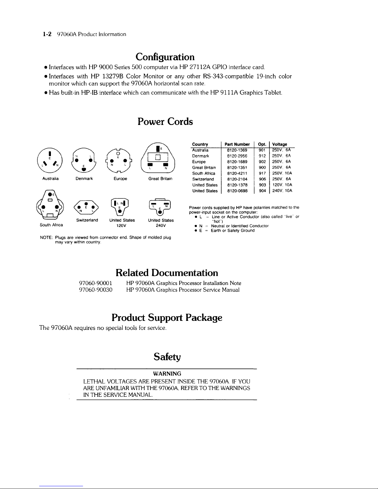
Power Cords
&§)
[QJ
••
L N
Great Britain
Q
L N
E
•
United States
240V
Country Part Number
Opt.
Voltage
Australia 8120-1369
901
250V, 6A
Denmark
8120·2956
912
250V, 6A
Europe 8120-1689
902
250V,
6A
Great Britain 8120-1351
900
250V,
6A
South Africa 8120-4211
917
250V,10A
Switzerland 8120-2104 906
250V.
6A
United
States 8120-1378 903
120V,10A
United States
8120-0698
904
240V,10A
Power cords supplied by HP have polarities matched
to
the
power-input socket on the computer:
• L = Line or Active Conductor (also called "live" or
"hot")
• N Neutral or Identified Conductor
•
E = Earth or Safety Ground
NOTE: Plugs are viewed from connector end. Shape of molded plug
may vary within country.
97060-90001
97060-90030
Related Documentation
HP
97060A Graphics Processor Installation Note
HP
97060A Graphics Processor Service Manual
Product Support Package
The 97060A requires no special tools
for
selVice.
Safety
WARNING
LETHAL
VOLTAGES ARE PRESENT INSIDE THE 97060A.
IF
YOU
ARE UNFAMILIAR
WITH
THE 97060A.
REFER
TO THE WARNINGS
IN
THE
SERVICE MANUAL.
Dimensions:
Temperature:
Humidity:
Altitude:
EM!:
Safety:
2-1
Chapter 2
97060A
Environmental/Installation/
Preventive Maintenance
Environmental Specifications
Width: 17 inches
Height:
5.25
inches
Length: 21 inches
-
40°C to + 75°C non-operating
O°C
to + 55°C operating
+ 40°C @
95%
non-condensing operating
50,000
feet, 0-55°C, non-operating
15,000 feet, 0-55°C, operating
VDE
Class A
FCC Class A
ULl14
(Office Machines)
UL478 (EDP)
CSA154 (EDP)
IEC380 (Office
Machines with
Amendment 1)
IEC435
(EDP 1982)
E1
2-2 97060A Environmental Installation,PM
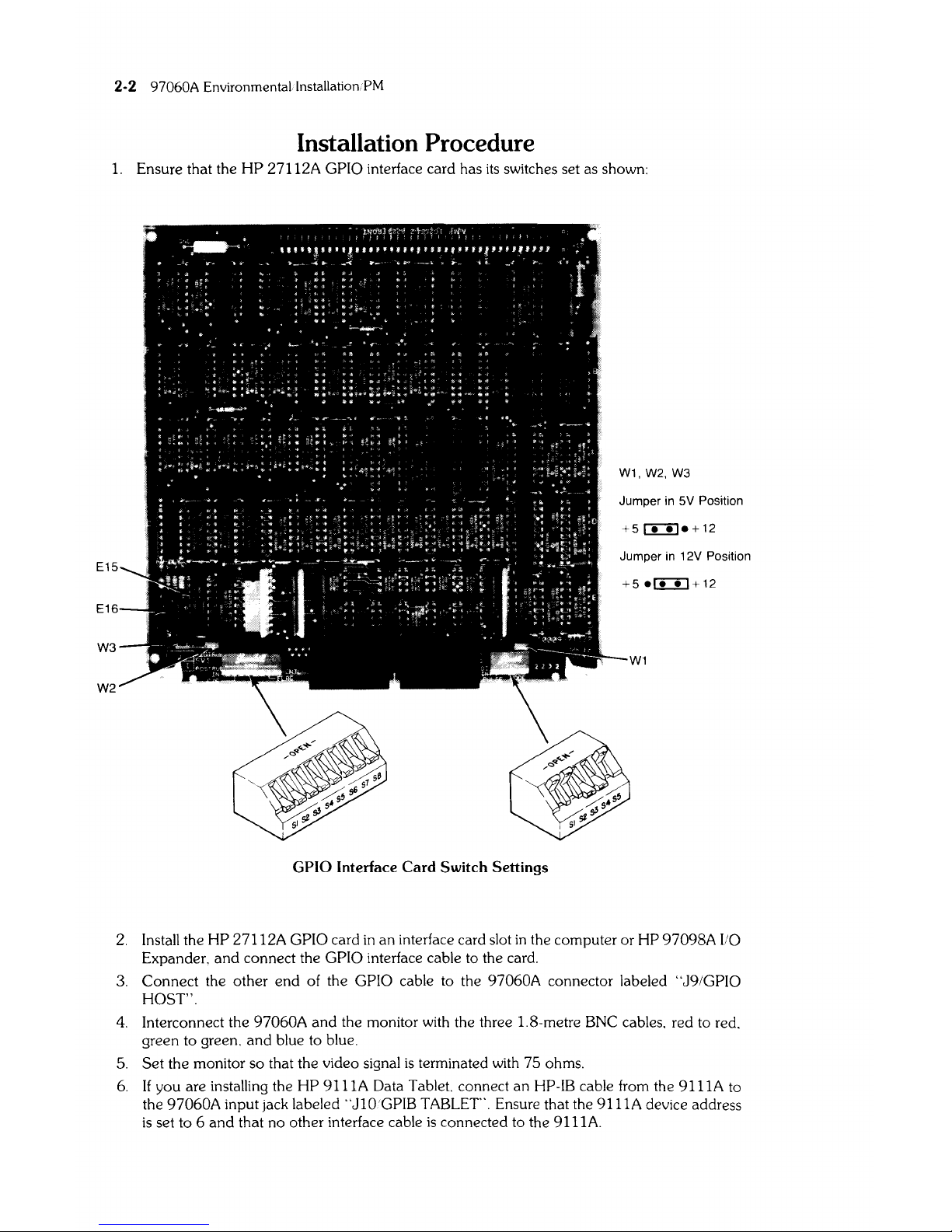
Installation Procedure
1.
Ensure that the
HP
27II2A
GPIO interface card has
its
switches set as shown:
W1,
W2,
W3
Jumper in 5V Position
+5
r:i:!le + 12
Jumper in 12V Position
+5
e£I:!J+12
W1
GPIO Interface Card Switch Settings
2.
Install the HP
27II2A
GPIO card
in
an interface card slot
in
the computer or HP 97098A
I/O
Expander. and connect the GPIO interface cable to the card.
3.
Connect the other
end
of the GPIO cable to the 97060A connector labeled "J9/GPIO
HOST".
4.
Interconnect the 97060A
and
the monitor with the three 1.8-metre BNC cables. red to red.
green to green.
and
blue to blue.
5.
Set the monitor so that the video signal
is
terminated
with
75 ohms.
6.
If you are installing the HP
911IA
Data Tablet. connect an HP-IB cable from the
9I11A
to
the
97060A input jack labeled
"JI0'GPIB
TABLET'. Ensure that the
9IIIA
device address
is
set to 6
and
that no other interface cable
is
connected to the
9IIIA.
97060A Environmental/Installation/PM 2-3
CAUTION
ENSURE
THAT
THE 97060A
IS
CONFIGURED
TO
MATCH THE
INPUT LINE VOLTAGE.
7.
Connect power cords to the 97060A, the monitor, and optionally to the 9111A.
8. Turn on power to the computer,
97060A, monitor,
and
optionally the 9111A.
9.
If the computer
is
a Model 520, load the System Integrity Test
and
run the
97060
test.
10.
If necessary, adjust the monitor's horizontal and/or vertical hold to get a stable picture.
Preventive Maintenance
There are no preventive maintenance procedures. Clean case parts as required according to the
following instructions.
CAUTION
CHEMICAL SPRAY -ON CLEANERS USED FOR APPLIANCES AND
OTHER HOUSEHOLD APPLICATIONS MAY DAMAGE THE FINISH. THESE
OR
OTHER CHEMICAL CLEANERS SHOULD NOT BE
USED. DO NOT USE DETERGENTS THAT CONTAIN AMMONIA,
BENZENES, CHLORIDES,
OR
ABRASIVES.
Clean case parts by wiping with a clean, lint-free cloth which has been dampened with a solution of
clean water and mild soap. A solution of
80% water and 20% isopropyl alcohol may be used for
heavily soiled areas.

2-4
97060A
Environmental InstaIJationPM
3-1
Chapter 3
97060A Configuration
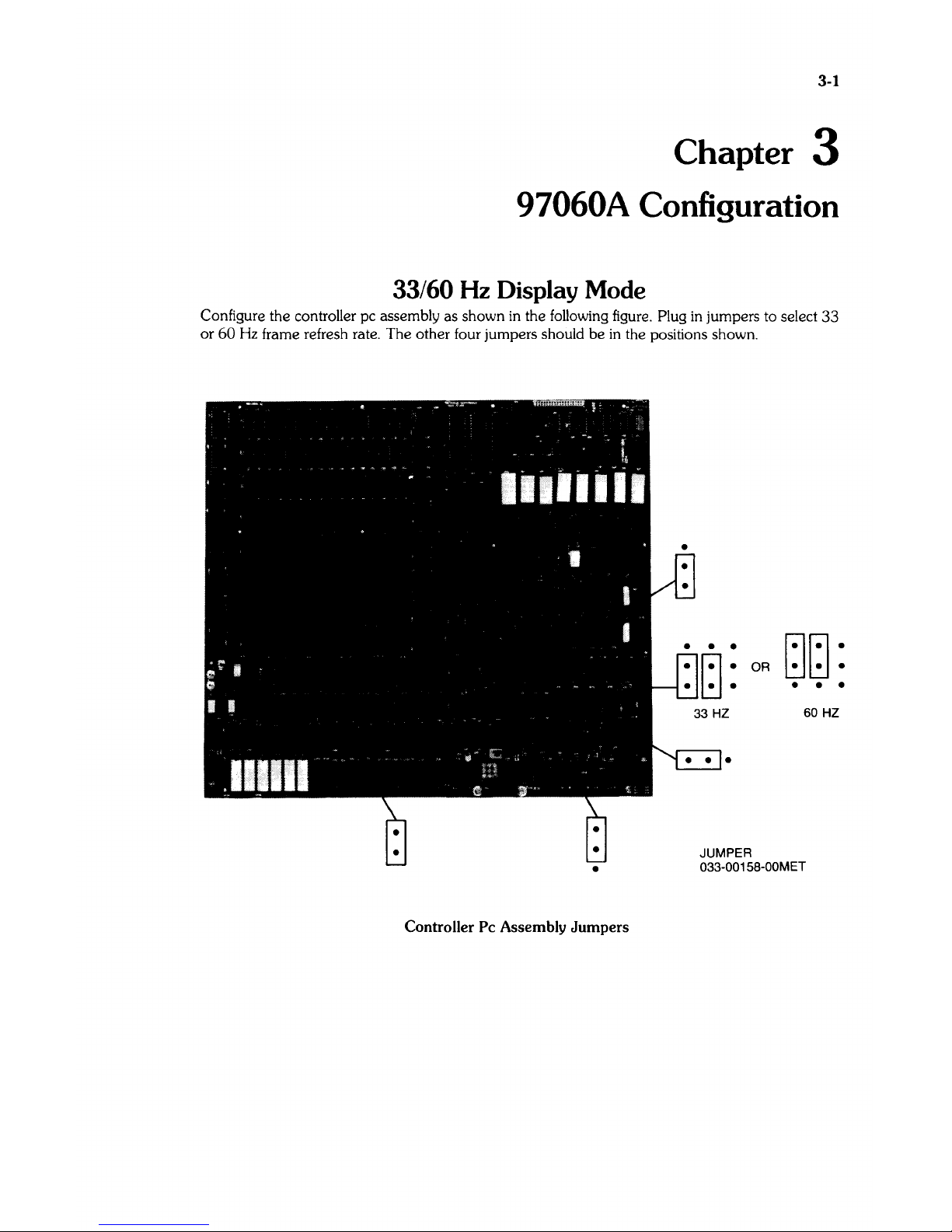
33/60
Hz
Display
Mode
Configure the controller pc assembly as shown
in
the following figure. Plug
in
jumpers to select
33
or
60
Hz
frame refresh rate. The other four jumpers should
be
in
the positions shown.
Controller Pc Assembly Jumpers
OR
~~:
• • •
60
HZ
•
JUMPER
033-001S8-00MET
 Loading...