

Page 1

advanced
configuration and
management guide
hp procurve routing switches
9304m, 9308m, and 6308m-sx
and the hp procurve switch
6208m-sx
www.hp.com/go/hpprocurve
(software release
6.6.x and 7.1.
x)
Page 2

Book 2:
Advanced Configuration and
Management Guide
for the HP ProCurve Routing Switches
9304M, 9308M, 6308M-SX
and the HP ProCurve Switch 6208M-SX
(Software Releases 6.6.X and 7.1.X)
Page 3

Copyright 2000
Hewlett-Packard Company
All rights reserved. Reproduction, adaptation or
translation without prior written permission is
prohibited, except as allowed under the copyright
laws.
Publication number
5969-2363
December 2000
Applicable Products
HP J4138A, HP J4139A, HP J4840A, HP J4841A
Trademark Credits
Microsoft
Internet Explorer
®
, Windows®, Microsoft Windows NT® and
®
are U.S. trademarks of Microsoft
Corporation. Netscape® Navigator is a U.S.
trademark of Netscape Communications
Corporation. Cisco® is a trademark of Cisco
Systems Inc.
Disclaimer
The information contained in this document is
subject to change without notice.
HEWLETT-PACKARD COMPANY MAKES NO
WARRANTY OF ANY KIND WITH REGARD TO
THIS MATERIAL, INCLUDING BUT NOT LIMITED
TO, THE IMPLIED WARRANTIES OF
MERCHANTABILITY AND FITNESS FOR A
PARTICULAR PURPOSE.
Hewlett-Packard shall not be liable for errors
contained herein or for incidental or consequential
damages in connection with the furnishing,
performance or use of this material.
Hewlett-Packard assumes no responsibility for the
use or reliability of its software on equipment that is
not furnished by Hewlett-Packard.
A copy of the specific warranty terms applicable to
your HP product and replacement parts can be
obtained from your HP Sales and Service Office or
authorized dealer.
Warranty
See the Customer Support and Warranty booklet
included with the product.
A copy of the specific warranty terms applicable to
your Hewlett-Packard products and replacement
parts can be obtained from your HP Sales and
Service Office or authorized dealer.
Safety Considerations
Prior to the installation and use of this product,
review all safety markings and instructions.
Instruction Manual Symbol.
If the product is marked with the above symbol, refer
to the product manual to protect the product from
damage.
WARNING Denotes a hazard that can cause injury.
CAUTION Denotes a hazard that can damage
equipment or data.
Do not proceed beyond a WARNING or CAUTION
notice until you have understood the hazard and
have taken appropriate precautions.
Use of control, adjustments or performance
procedures other than those specified herein may
result in hazardous radiation exposure.
Grounding
This product provides a protective earthing terminal.
There must be an uninterrupted safety earth ground
from the main power source to the product’s input
wiring terminals, power cord or supplied power cord
set. Whenever it is likely that the protection has
been impaired, disconnect the power cord until the
ground has been restored.
If your LAN covers an area served by more than one
power distribution system, be sure their safety
grounds are securely interconnected.
LAN cables may occasionally be subject to
hazardous transient voltages (such as lightning or
disturbances in the electrical utilities power grid).
Handle exposed metal components of the network
with caution.
For more safety information, see “Safety and EMS
Regulatory Statements” in the Installation and
Getting Started Guide.
Servicing
There are no user-serviceable parts inside the userinstallable modules comprising the product. Any
servicing, adjustment, maintenance or repair must
be performed only by service-trained personnel.
ii
Page 4

Organization of Product Documentation
Read Me First
The “Read Me First” document includes software release information, a brief “Getting Started” section, an
accessory parts list, troubleshooting tips, operating notes, and other information that is not included elsewhere in
the product documentation.
NOTE: HP periodically updates Read Me First. The latest version is available at
http://www.hp.com/go/hpprocurve. (Click on Technical Support, then Manuals.)
Main Product Coverage
The main product documentation for your switch or routing switch includes:
• Book 1: Installation and Getting Started Guide. Book 1 contains the product Safety and EMC Regulatory
statements as well as installation, security, and basic configuration information. A printed copy of this guide is
included with your HP product. An electronic copy is also included as a PDF (Portable Document Format) file
on the CD shipped with your HP product.
• Book 2: Advanced Configuration and Management Guide. Book 2 (this manual) contains advanced
configuration information for routing protocols, Spanning Tree Protocol (STP), Quality of Service (QoS), and
Virtual LANs (VLANs). In addition, appendixes in this guide contain reference information for network
monitoring, policies and filters, and software and hardware specifications. This manual is included in a PDF
(Portable Document Format) file on the CD shipped with your HP product.
• Book 3: Command Line Interface Reference. Book 3 provides a dictionary of CLI commands and syntax. An
electronic copy of this reference is included as a PDF (Portable Document Format) file on the CD shipped
with your HP product.
These documents also are available in PDF file format on HP's ProCurve website.
NOTE: In Book 2, most of the chapters apply only to the HP 9304M, HP 9308M, and HP 6308M-SX routing
switches (and not the HP 6208M-SX switch). However, the QoS, ACL, STP, and VLAN chapters, and appendixes
A and B apply to the HP 6208M-SX switch as well as the routing switches.
Product CD: A Tool for Finding Specific Information and/or Printing Selected Pages
This CD is shipped with your HP product and provides the following:
• A README.txt file (or README.pdf file) describing the CD contents and use, including easy instructions on
how to search the book files for specific information
• A contents.pdf file to give you easy access to Book 1, Book 2, and the CLI Reference on the CD
• Separate PDF files of the individual chapters and appendixes in Book 1 and Book 2, enabling you to easily
print individual chapters, appendixes, and selected pages
• Single PDF files for each of the books, enabling you to use the Adobe® Acrobat® Reader to easily search for
detailed information
• An Adobe Acrobat Reader (in case you don't already have a reader installed on your PC)
• Additional files. These may include such items as a copy of the device software (OS), additional Readme
files, and updates to network management software (HP TopTools for Hubs & Switches).
Supplements and Release Notes
These documents describe features that became available between revisions of the main product documentation.
Depending on when new features are released, you may or may not receive any supplements or release notes
with your HP product. New releases of such documents will be available on HP's ProCurve website. To register
to receive email notice from HP when a new software release is available, go to
http://www.hp.com/go/hpprocurve and click on Technical Support, then Software.
iii
Page 5

iv
Page 6

Contents
GETTING STARTED...................................................................................... 1-1
INTRODUCTION ...........................................................................................................................................1-1
A
UDIENCE ..................................................................................................................................................1-1
N
OMENCLATURE .........................................................................................................................................1-1
ERMINOLOGY ............................................................................................................................................1-2
T
R
ELATED PUBLICATIONS .............................................................................................................................1-2
W
HAT’S NEW IN THIS EDITION? ...................................................................................................................1-3
NHANCEMENTS ADDED IN SOFTWARE RELEASE 06.6.X .......................................................................1-3
E
E
NHANCEMENTS ADDED IN SOFTWARE RELEASE 07.1.X .......................................................................1-3
S
UPPORT AND WARRANTY INFORMATION .....................................................................................................1-5
QUALITY OF SERVICE (QOS)....................................................................... 2-1
THE QUEUES ..............................................................................................................................................2-1
UTOMATIC QUEUE MAPPING FOR IP TYPE OF SERVICE (TOS) VALUES ...............................................2-2
A
Q
UEUING METHODS ....................................................................................................................................2-3
S
ELECTING THE QUEUING METHOD .......................................................................................................2-3
ONFIGURING THE QUEUES ..................................................................................................................2-4
C
D
ISPLAYING THE QOS PROFILE CONFIGURATION .......................................................................................2-10
A
SSIGNING QOS PRIORITIES TO TRAFFIC ..................................................................................................2-11
HANGING A PORT’S PRIORITY ...........................................................................................................2-11
C
C
HANGING A LAYER 2 PORT-BASED VLAN’S PRIORITY .......................................................................2-12
R
EASSIGNING 802.1P PRIORITIES TO DIFFERENT QUEUES ...................................................................2-14
SSIGNING STATIC MAC ENTRIES TO PRIORITY QUEUES ....................................................................2-16
A
A
SSIGNING IP AND LAYER 4 SESSIONS TO PRIORITY QUEUES .............................................................2-17
A
SSIGNING APPLETALK SOCKETS TO PRIORITY QUEUES .....................................................................2-25
ONFIGURING A UTILIZATION LIST FOR AN UPLINK PORT ............................................................................2-26
C
D
ISPLAYING UTILIZATION PERCENTAGES FOR AN UPLINK ...........................................................................2-28
USING ACCESS CONTROL LISTS (ACLS)..................................................... 3-1
OVERVIEW ..................................................................................................................................................3-1
v
Page 7

Advanced Configuration and Management Guide
USAGE GUIDELINES FOR ACCESS CONTROL LISTS (ACLS) ..........................................................................3-2
ACL S
UPPORT ON THE HP PRODUCTS .................................................................................................3-2
ACL ID
D
C
S AND ENTRIES .........................................................................................................................3-2
EFAULT ACL ACTION .........................................................................................................................3-3
ONTROLLING MANAGEMENT ACCESS TO THE DEVICE ..........................................................................3-3
ACL LOGGING .....................................................................................................................................3-3
ISABLING OR RE-ENABLING ACCESS CONTROL LISTS (ACLS) ....................................................................3-4
D
E
NABLING ACL MODE ..........................................................................................................................3-4
DISABLING ACL MODE .........................................................................................................................3-5
ONFIGURING STANDARD ACLS .................................................................................................................3-5
C
S
TANDARD ACL SYNTAX ......................................................................................................................3-6
CONFIGURING EXTENDED ACLS ..................................................................................................................3-9
F
ILTERING ON IP PRECEDENCE AND TOS VALUES ..............................................................................3-10
XTENDED ACL SYNTAX ....................................................................................................................3-11
E
CONFIGURING NAMED ACLS .....................................................................................................................3-18
M
ODIFYING ACLS .....................................................................................................................................3-19
PPLYING AN ACL TO A SUBSET OF PORTS ON A VIRTUAL INTERFACE .......................................................3-21
A
E
NABLING STRICT TCP OR UDP MODE ....................................................................................................3-21
E
NABLING STRICT TCP MODE ............................................................................................................3-22
NABLING STRICT UDP MODE ...........................................................................................................3-22
E
D
ISPLAYING ACLS ....................................................................................................................................3-23
D
ISPLAYING THE LOG ENTRIES ..................................................................................................................3-23
OLICY-BASED ROUTING (PBR) ................................................................................................................3-24
P
C
ONFIGURING PBR ............................................................................................................................3-25
E
NABLING PBR ..................................................................................................................................3-27
ONFIGURATION EXAMPLES ...............................................................................................................3-27
C
RATE LIMITING............................................................................................ 4-1
FIXED RATE LIMITING ..................................................................................................................................4-1
H
OW FIXED RATE LIMITING WORKS ......................................................................................................4-1
C
ONFIGURING FIXED RATE LIMITING .....................................................................................................4-2
ISPLAYING FIXED RATE LIMITING INFORMATION ...................................................................................4-3
D
A
DAPTIVE RATE LIMITING ............................................................................................................................4-4
E
XAMPLES OF ADAPTIVE RATE LIMITING APPLICATIONS .........................................................................4-5
DAPTIVE RATE LIMITING PARAMETERS ................................................................................................4-8
A
H
OW ADAPTIVE RATE LIMITING WORKS ..............................................................................................4-10
C
ONFIGURING ADAPTIVE RATE LIMITING .............................................................................................4-13
OMPLETE CLI EXAMPLES .................................................................................................................4-18
C
D
ISABLING RATE LIMITING EXEMPTION FOR CONTROL PACKETS ..........................................................4-20
CONFIGURING SPANNING TREE PROTOCOL (STP) ....................................... 5-1
CONFIGURING STANDARD STP PARAMETERS ..............................................................................................5-1
STP P
ARAMETERS AND DEFAULTS .......................................................................................................5-2
NABLING OR DISABLING THE SPANNING TREE PROTOCOL (STP) .........................................................5-3
E
C
HANGING STP BRIDGE AND PORT PARAMETERS .................................................................................5-4
D
ISPLAYING STP INFORMATION ............................................................................................................5-7
vi
Page 8

CONFIGURING ADVANCED FEATURES ........................................................................................................5-13
F
AST PORT SPAN ...............................................................................................................................5-13
F
AST UPLINK SPAN ............................................................................................................................5-15
INGLE SPANNING TREE ....................................................................................................................5-17
S
PVST/PVST+ C
OMPATIBILITY ............................................................................................................5-20
ENABLING PVST/PVST+ STATICALLY ................................................................................................5-21
ISPLAYING PVST INFORMATION ........................................................................................................5-22
D
CONFIGURING IP......................................................................................... 6-1
BASIC CONFIGURATION ...............................................................................................................................6-1
O
VERVIEW ..................................................................................................................................................6-2
IP INTERFACES ....................................................................................................................................6-2
IP P
ACKET FLOW THROUGH A ROUTING SWITCH ..................................................................................6-3
OUTE EXCHANGE PROTOCOLS .......................................................................................................6-7
IP R
IP MULTICAST PROTOCOLS ..................................................................................................................6-7
IP I
NTERFACE REDUNDANCY PROTOCOLS .............................................................................................6-7
ETWORK ADDRESS TRANSLATION .......................................................................................................6-8
N
A
CCESS CONTROL LISTS AND IP ACCESS POLICIES ..............................................................................6-8
B
ASIC IP PARAMETERS AND DEFAULTS – ROUTING SWITCHES .....................................................................6-9
HEN PARAMETER CHANGES TAKE EFFECT .........................................................................................6-9
W
IP G
LOBAL PARAMETERS – ROUTING SWITCHES .................................................................................6-10
IP I
NTERFACE PARAMETERS – ROUTING SWITCHES ............................................................................6-14
ASIC IP PARAMETERS AND DEFAULTS – HP 6208M-SX ..........................................................................6-16
B
IP G
LOBAL PARAMETERS – HP 6208M-SX ........................................................................................6-16
I
NTERFACE IP PARAMETERS – HP 6208M-SX ....................................................................................6-17
ONFIGURING IP PARAMETERS – ROUTING SWITCHES ..............................................................................6-18
C
C
ONFIGURING IP ADDRESSES ............................................................................................................6-18
C
ONFIGURING DOMAIN NAME SERVER (DNS) RESOLVER ....................................................................6-21
ONFIGURING PACKET PARAMETERS ..................................................................................................6-23
C
C
HANGING THE ROUTER ID ................................................................................................................6-25
S
PECIFYING A SINGLE SOURCE INTERFACE FOR TELNET, TACACS/TACACS+, OR RADIUS PACKETS ...6-
26
ONFIGURING ARP PARAMETERS ......................................................................................................6-27
C
C
ONFIGURING FORWARDING PARAMETERS .........................................................................................6-32
ISABLING ICMP MESSAGES .............................................................................................................6-34
D
D
ISABLING ICMP REDIRECTS .............................................................................................................6-36
C
ONFIGURING STATIC ROUTES ...........................................................................................................6-36
ONFIGURING A DEFAULT NETWORK ROUTE .......................................................................................6-46
C
C
ONFIGURING IP LOAD SHARING ........................................................................................................6-48
O
PTIMIZING THE IP FORWARDING CACHE ............................................................................................6-60
ONFIGURING IRDP ...........................................................................................................................6-62
C
C
ONFIGURING RARP .........................................................................................................................6-64
C
ONFIGURING UDP BROADCAST AND IP HELPER PARAMETERS ..........................................................6-67
ONFIGURING BOOTP/DHCP FORWARDING PARAMETERS ..................................................................6-70
C
C
ONFIGURING IP PARAMETERS – HP 6208M-SX ......................................................................................6-73
C
ONFIGURING THE MANAGEMENT IP ADDRESS AND SPECIFYING THE DEFAULT GATEWAY ....................6-73
vii
Page 9

Advanced Configuration and Management Guide
CONFIGURING DOMAIN NAME SERVER (DNS) RESOLVER ....................................................................6-74
C
HANGING THE TTL THRESHOLD ........................................................................................................6-76
C
ONFIGURING DHCP ASSIST .............................................................................................................6-76
ISPLAYING IP CONFIGURATION INFORMATION AND STATISTICS .................................................................6-80
D
C
HANGING THE NETWORK MASK DISPLAY TO PREFIX FORMAT ............................................................6-80
DISPLAYING IP INFORMATION – ROUTING SWITCHES ...........................................................................6-80
ISPLAYING IP INFORMATION – HP 6208M-SX .................................................................................6-100
D
CONFIGURING RIP ...................................................................................... 7-1
ICMP HOST UNREACHABLE MESSAGE FOR UNDELIVERABLE ARPS .......................................................7-1
RIP P
ARAMETERS AND DEFAULTS ...............................................................................................................7-1
RIP GLOBAL PARAMETERS ...................................................................................................................7-1
RIP I
NTERFACE PARAMETERS ..............................................................................................................7-3
ONFIGURING RIP PARAMETERS ................................................................................................................7-3
C
ENABLING RIP .....................................................................................................................................7-3
C
HANGING THE RIP TYPE ON A PORT ...................................................................................................7-4
ONFIGURING METRIC PARAMETERS ....................................................................................................7-5
C
C
HANGING THE ADMINISTRATIVE DISTANCE ..........................................................................................7-6
C
ONFIGURING REDISTRIBUTION ............................................................................................................7-7
ONFIGURING ROUTE LEARNING AND ADVERTISING PARAMETERS .........................................................7-9
C
C
HANGING THE ROUTE LOOP PREVENTION METHOD ...........................................................................7-12
S
UPPRESSING RIP ROUTE ADVERTISEMENT ON A VRRP OR VRRPE BACKUP INTERFACE ...................7-13
ONFIGURING RIP ROUTE FILTERS ....................................................................................................7-13
C
D
ISPLAYING RIP FILTERS ..........................................................................................................................7-16
CONFIGURING OSPF .................................................................................. 8-1
OVERVIEW OF OSPF ..................................................................................................................................8-1
D
ESIGNATED ROUTERS IN MULTI-ACCESS NETWORKS ...........................................................................8-2
ESIGNATED ROUTER ELECTION ..........................................................................................................8-3
D
OSPF RFC 1583
R
EDUCTION OF EQUIVALENT AS EXTERNAL LSAS .................................................................................8-4
YNAMIC OSPF ACTIVATION AND CONFIGURATION ...............................................................................8-6
D
D
YNAMIC OSPF MEMORY ....................................................................................................................8-6
C
ONFIGURING OSPF ..................................................................................................................................8-7
ONFIGURATION RULES .......................................................................................................................8-7
C
OSPF P
E
A
A
A
M
B
A
M
D
M
ARAMETERS ............................................................................................................................8-7
NABLE OSPF ON THE ROUTING SWITCH .............................................................................................8-8
SSIGN OSPF AREAS ..........................................................................................................................8-9
SSIGNING AN AREA RANGE (OPTIONAL) ............................................................................................8-15
SSIGNING INTERFACES TO AN AREA ..................................................................................................8-16
ODIFY INTERFACE DEFAULTS ...........................................................................................................8-18
LOCK FLOODING OF OUTBOUND LSAS ON SPECIFIC OSPF INTERFACES ...........................................8-20
SSIGN VIRTUAL LINKS ......................................................................................................................8-20
ODIFY VIRTUAL LINK PARAMETERS ...................................................................................................8-23
EFINE REDISTRIBUTION FILTERS .......................................................................................................8-24
ODIFY DEFAULT METRIC FOR REDISTRIBUTION .................................................................................8-27
AND 2178 COMPLIANCE ...........................................................................................8-4
viii
Page 10

ENABLE ROUTE REDISTRIBUTION ........................................................................................................8-28
D
ISABLE OR RE-ENABLE LOAD SHARING .............................................................................................8-30
C
ONFIGURE EXTERNAL ROUTE SUMMARIZATION .................................................................................8-31
ONFIGURE DEFAULT ROUTE ORIGINATION .........................................................................................8-32
C
M
ODIFY SPF TIMERS .........................................................................................................................8-33
MODIFY REDISTRIBUTION METRIC TYPE ..............................................................................................8-33
ODIFY ADMINISTRATIVE DISTANCE ....................................................................................................8-34
M
C
ONFIGURE OSPF GROUP LINK STATE ADVERTISEMENT (LSA) PACING .............................................8-34
MODIFY OSPF TRAPS GENERATED ....................................................................................................8-35
ODIFY OSPF STANDARD COMPLIANCE SETTING ...............................................................................8-36
M
M
ODIFY EXIT OVERFLOW INTERVAL ....................................................................................................8-37
MODIFY THE MAXIMUM NUMBER OF ROUTES .......................................................................................8-37
M
ODIFY LSDB LIMITS ........................................................................................................................8-38
ISPLAYING OSPF INFORMATION ..............................................................................................................8-39
D
DISPLAYING GENERAL OSPF CONFIGURATION INFORMATION ..............................................................8-39
D
ISPLAYING OSPF AREA INFORMATION ..............................................................................................8-40
ISPLAYING OSPF NEIGHBOR INFORMATION ......................................................................................8-41
D
D
ISPLAYING OSPF INTERFACE INFORMATION ......................................................................................8-43
D
ISPLAYING OSPF ROUTE INFORMATION ............................................................................................8-43
ISPLAYING OSPF EXTERNAL LINK STATE INFORMATION ....................................................................8-45
D
D
ISPLAYING OSPF LINK STATE INFORMATION .....................................................................................8-46
D
ISPLAYING THE DATA IN AN LSA .......................................................................................................8-46
ISPLAYING OSPF VIRTUAL NEIGHBOR INFORMATION .........................................................................8-47
D
D
ISPLAYING OSPF VIRTUAL LINK INFORMATION ..................................................................................8-47
D
ISPLAYING OSPF ABR AND ASBR INFORMATION .............................................................................8-48
ISPLAYING OSPF TRAP STATUS .......................................................................................................8-48
D
CONFIGURING IP MULTICAST PROTOCOLS................................................... 9-1
OVERVIEW OF IP MULTICASTING .................................................................................................................9-1
M
ULTICAST TERMS ...............................................................................................................................9-1
C
HANGING GLOBAL IP MULTICAST PARAMETERS .........................................................................................9-2
HANGING IGMP PARAMETERS ............................................................................................................9-2
C
E
NABLING HARDWARE FORWARDING FOR ALL FRAGMENTS OF IP MULTICAST PACKETS .........................9-4
PIM D
ENSE OVERVIEW ...............................................................................................................................9-4
NITIATING PIM MULTICASTS ON A NETWORK ........................................................................................9-4
I
P
RUNING A MULTICAST TREE ...............................................................................................................9-4
G
RAFTS TO A MULTICAST TREE ............................................................................................................9-6
ONFIGURING PIM .....................................................................................................................................9-7
C
E
NABLING PIM ON THE ROUTING SWITCH AND AN INTERFACE ...............................................................9-7
M
ODIFYING PIM GLOBAL PARAMETERS ................................................................................................9-8
ODIFYING PIM INTERFACE PARAMETERS ..........................................................................................9-11
M
PIM S
PARSE OVERVIEW ...........................................................................................................................9-12
PIM S
PARSE ROUTER TYPES .............................................................................................................9-12
ATHS AND SPT PATHS ...............................................................................................................9-13
RP P
C
ONFIGURING PIM SPARSE ......................................................................................................................9-13
L
IMITATIONS IN THIS RELEASE ............................................................................................................9-13
ix
Page 11

Advanced Configuration and Management Guide
CONFIGURING GLOBAL PARAMETERS ..................................................................................................9-14
C
ONFIGURING PIM INTERFACE PARAMETERS ......................................................................................9-14
C
ONFIGURING PIM SPARSE GLOBAL PARAMETERS .............................................................................9-15
TATICALLY SPECIFYING THE RP ........................................................................................................9-16
S
C
HANGING THE SHORTEST PATH TREE (SPT) THRESHOLD .................................................................9-17
CHANGING THE PIM JOIN AND PRUNE MESSAGE INTERVAL .................................................................9-17
ISPLAYING PIM SPARSE CONFIGURATION INFORMATION AND STATISTICS ...........................................9-18
D
C
ONFIGURING MULTICAST SOURCE DISCOVERY PROTOCOL (MSDP) .........................................................9-29
PEER REVERSE PATH FORWARDING (RPF) FLOODING ........................................................................9-30
OURCE ACTIVE CACHING ..................................................................................................................9-31
S
C
ONFIGURING MSDP .........................................................................................................................9-31
DISPLAYING MSDP INFORMATION .......................................................................................................9-32
C
LEARING MSDP INFORMATION .........................................................................................................9-38
DVMRP O
VERVIEW ..................................................................................................................................9-39
INITIATING DVMRP MULTICASTS ON A NETWORK ...............................................................................9-39
P
RUNING A MULTICAST TREE .............................................................................................................9-39
RAFTS TO A MULTICAST TREE ..........................................................................................................9-41
G
C
ONFIGURING DVMRP .............................................................................................................................9-42
E
NABLING DVMRP ON THE ROUTING SWITCH AND INTERFACE ............................................................9-42
ODIFYING DVMRP GLOBAL PARAMETERS ........................................................................................9-43
M
M
ODIFYING DVMRP INTERFACE PARAMETERS ...................................................................................9-47
C
ONFIGURING AN IP TUNNEL ....................................................................................................................9-50
ONFIGURING A STATIC MULTICAST ROUTE ..............................................................................................9-51
C
T
RACING A MULTICAST ROUTE ..................................................................................................................9-53
D
ISPLAYING ANOTHER MULTICAST ROUTER’S MULTICAST CONFIGURATION ................................................9-55
CONFIGURING BGP4 ................................................................................ 10-1
OVERVIEW OF BGP4 ................................................................................................................................10-1
ELATIONSHIP BETWEEN THE BGP4 ROUTE TABLE AND THE IP ROUTE TABLE ....................................10-2
R
H
OW BGP4 SELECTS A PATH FOR A ROUTE .......................................................................................10-3
BGP4 M
ASIC CONFIGURATION AND ACTIVATION FOR BGP4 .................................................................................10-6
B
N
OTE REGARDING DISABLING BGP4 ..................................................................................................10-6
BGP4 P
W
M
EMORY CONSIDERATIONS .......................................................................................................................10-9
M
ONFIGURING BGP4 ..............................................................................................................................10-10
C
B
ASIC CONFIGURATION TASKS ................................................................................................................10-11
E
NABLING BGP4 ON THE ROUTING SWITCH ......................................................................................10-11
HANGING THE ROUTER ID ..............................................................................................................10-11
C
S
ETTING THE LOCAL AS NUMBER .....................................................................................................10-12
A
DDING A LOOPBACK INTERFACE ......................................................................................................10-13
DDING BGP4 NEIGHBORS ..............................................................................................................10-14
A
A
DDING A BGP4 PEER GROUP ........................................................................................................10-19
O
PTIONAL CONFIGURATION TASKS ..........................................................................................................10-23
ESSAGE TYPES .....................................................................................................................10-4
ARAMETERS .................................................................................................................................10-7
HEN PARAMETER CHANGES TAKE EFFECT .......................................................................................10-9
EMORY CONFIGURATION OPTIONS OBSOLETED BY DYNAMIC MEMORY ............................................10-10
x
Page 12

CHANGING THE KEEP ALIVE TIME AND HOLD TIME ............................................................................10-23
E
NABLING FAST EXTERNAL FALLOVER ..............................................................................................10-24
C
HANGING THE MAXIMUM NUMBER OF PATHS FOR BGP4 LOAD SHARING .........................................10-25
PECIFYING A LIST OF NETWORKS TO ADVERTISE .............................................................................10-26
S
C
HANGING THE DEFAULT LOCAL PREFERENCE ..................................................................................10-28
ADVERTISING THE DEFAULT INFORMATION ORIGINATE .......................................................................10-29
HANGING THE DEFAULT MED (METRIC) USED FOR ROUTE REDISTRIBUTION ....................................10-29
C
C
HANGING ADMINISTRATIVE DISTANCES ...........................................................................................10-30
CONFIGURING THE ROUTING SWITCH TO ALWAYS COMPARE MULTI-EXIT DISCRIMINATORS (MEDS) ....10-31
YNCHRONIZING ROUTES .................................................................................................................10-32
S
A
UTOMATICALLY SUMMARIZING SUBNET ROUTES INTO CLASS A, B, OR C NETWORKS .......................10-32
CONFIGURING ROUTE REFLECTION PARAMETERS .............................................................................10-33
C
ONFIGURING CONFEDERATIONS ......................................................................................................10-36
GGREGATING ROUTES ADVERTISED TO BGP4 NEIGHBORS .............................................................10-39
A
MODIFYING REDISTRIBUTION PARAMETERS .......................................................................................10-41
F
ILTERING SPECIFIC IP ADDRESSES .................................................................................................10-44
ILTERING AS-PATHS .......................................................................................................................10-46
F
F
ILTERING COMMUNITIES ..................................................................................................................10-51
D
EFINING IP PREFIX LISTS ...............................................................................................................10-55
EFINING NEIGHBOR DISTRIBUTE LISTS ............................................................................................10-57
D
D
EFINING ROUTE MAPS ...................................................................................................................10-59
U
SING A TABLE MAP TO SET THE TAG VALUE ...................................................................................10-68
ONFIGURING ROUTE FLAP DAMPENING .................................................................................................10-69
C
G
LOBALLY CONFIGURING ROUTE FLAP DAMPENING ..........................................................................10-69
U
SING A ROUTE MAP TO CONFIGURE ROUTE FLAP DAMPENING FOR SPECIFIC ROUTES ....................10-71
SING A ROUTE MAP TO CONFIGURE ROUTE FLAP DAMPENING FOR A SPECIFIC NEIGHBOR ..............10-76
U
R
EMOVING ROUTE DAMPENING FROM A ROUTE ................................................................................10-78
D
ISPLAYING AND CLEARING ROUTE FLAP DAMPENING STATISTICS .....................................................10-79
TATICALLY ALLOCATING MEMORY FOR THE HP 6308M-SX ROUTING SWITCH ........................................10-80
S
C
HANGING THE MAXIMUM NUMBER OF NEIGHBORS ...........................................................................10-80
C
HANGING THE MAXIMUM NUMBER OF ROUTES ................................................................................10-81
HANGING THE MAXIMUM NUMBER OF ROUTE-ATTRIBUTE ENTRIES ...................................................10-82
C
D
ISPLAYING BGP4 INFORMATION ............................................................................................................10-84
D
ISPLAYING SUMMARY BGP4 INFORMATION .....................................................................................10-84
ISPLAYING THE ACTIVE BGP4 CONFIGURATION ..............................................................................10-87
D
D
ISPLAYING SUMMARY NEIGHBOR INFORMATION ...............................................................................10-88
D
ISPLAYING BGP4 NEIGHBOR INFORMATION .....................................................................................10-90
ISPLAYING SUMMARY ROUTE INFORMATION ..................................................................................10-102
D
D
ISPLAYING THE BGP4 ROUTE TABLE ............................................................................................10-102
D
ISPLAYING BGP4 ROUTE-ATTRIBUTE ENTRIES ..............................................................................10-109
ISPLAYING THE ROUTES BGP4 HAS PLACED IN THE IP ROUTE TABLE ...........................................10-111
D
D
ISPLAYING ROUTE FLAP DAMPENING STATISTICS ..........................................................................10-111
D
ISPLAYING THE ACTIVE ROUTE MAP CONFIGURATION ....................................................................10-113
LEARING TRAFFIC COUNTERS .............................................................................................................10-113
C
C
LEARING ROUTE FLAP DAMPENING STATISTICS ...................................................................................10-114
U
PDATING ROUTE INFORMATION AND RESETTING A NEIGHBOR SESSION ................................................10-114
xi
Page 13

Advanced Configuration and Management Guide
DYNAMICALLY REQUESTING A ROUTE REFRESH FROM A BGP4 NEIGHBOR ......................................10-114
C
LOSING OR RESETTING A NEIGHBOR SESSION ..............................................................................10-116
R
EMOVING ROUTE FLAP DAMPENING ....................................................................................................10-117
LEARING DIAGNOSTIC BUFFERS ..........................................................................................................10-118
C
NETWORK ADDRESS TRANSLATION ........................................................... 11-1
PORT ADDRESS TRANSLATION ..................................................................................................................11-3
M
AXIMUM NUMBER OF ADDRESSES ....................................................................................................11-4
PROTOCOLS SUPPORTED FOR NAT ..........................................................................................................11-4
ONFIGURING NAT ..................................................................................................................................11-4
C
C
ONFIGURING STATIC ADDRESS TRANSLATIONS ..................................................................................11-5
CONFIGURING DYNAMIC NAT PARAMETERS ........................................................................................11-5
E
NABLING NAT ..................................................................................................................................11-7
HANGING TRANSLATION TABLE TIMEOUTS .........................................................................................11-7
C
DISPLAYING THE ACTIVE NAT TRANSLATIONS ...........................................................................................11-8
D
ISPLAYING NAT STATISTICS ...................................................................................................................11-9
LEARING TRANSLATION TABLE ENTRIES ................................................................................................11-11
C
NAT D
EBUG COMMANDS ........................................................................................................................11-12
C
ONFIGURATION EXAMPLES ....................................................................................................................11-14
RIVATE NAT CLIENTS CONNECTED TO THE ROUTING SWITCH BY A SWITCH ......................................11-14
P
P
RIVATE NAT CLIENTS CONNECTED DIRECTLY TO THE ROUTING SWITCH ...........................................11-16
CONFIGURING VRRP AND VRRPE ........................................................... 12-1
OVERVIEW ................................................................................................................................................12-2
O
VERVIEW OF VRRP .........................................................................................................................12-2
VERVIEW OF VRRPE .......................................................................................................................12-6
O
C
OMPARISON OF VRRP, VRRPE, AND SRP .............................................................................................12-8
VRRP ...............................................................................................................................................12-8
VRRPE .............................................................................................................................................12-8
SRP ..................................................................................................................................................12-8
ARCHITECTURAL DIFFERENCES ...........................................................................................................12-8
AND VRRPE PARAMETERS ............................................................................................................12-9
VRRP
C
ONFIGURING BASIC VRRP PARAMETERS ..............................................................................................12-12
C
ONFIGURING THE OWNER ...............................................................................................................12-12
ONFIGURING A BACKUP ..................................................................................................................12-12
C
C
ONFIGURATION RULES FOR VRRP .................................................................................................12-12
C
ONFIGURING BASIC VRRPE PARAMETERS ............................................................................................12-13
ONFIGURATION RULES FOR VRRPE ...............................................................................................12-13
C
N
OTE REGARDING DISABLING VRRP OR VRRPE ....................................................................................12-13
C
ONFIGURING ADDITIONAL VRRP AND VRRPE PARAMETERS .................................................................12-13
ORCING A MASTER ROUTER TO ABDICATE TO A STANDBY ROUTER ........................................................12-18
F
D
ISPLAYING VRRP AND VRRPE INFORMATION .......................................................................................12-19
D
ISPLAYING SUMMARY INFORMATION ................................................................................................12-19
ISPLAYING DETAILED INFORMATION ................................................................................................12-21
D
D
ISPLAYING STATISTICS ...................................................................................................................12-26
C
LEARING VRRP OR VRRPE STATISTICS ........................................................................................12-30
xii
Page 14

CONFIGURATION EXAMPLES ....................................................................................................................12-30
VRRP E
VRRPE E
XAMPLE ..............................................................................................................................12-30
XAMPLE ............................................................................................................................12-34
CONFIGURING SRP................................................................................... 13-1
OVERVIEW OF STANDBY ROUTER PROTOCOL (SRP) .................................................................................13-2
SRP S
A
TRACK PORTS ....................................................................................................................................13-3
I
D
DIFFERENCES BETWEEN SRP AND VRRP .................................................................................................13-7
C
ONFIGURING SRP ..................................................................................................................................13-7
C
ENABLE SRP ON THE ROUTING SWITCH .............................................................................................13-8
A
A
A
M
C
UPPORT ON VIRTUAL INTERFACES ............................................................................................13-3
CTIVE AND STANDBY ROUTERS .........................................................................................................13-3
NDEPENDENT OPERATION OF RIP AND OSPF ....................................................................................13-6
YNAMIC SRP CONFIGURATION .........................................................................................................13-6
ONFIGURATION RULES FOR SRP ......................................................................................................13-8
SSIGN VIRTUAL ROUTER IP ADDRESSES ...........................................................................................13-9
SSIGN THE TRACK PORT(S) ............................................................................................................13-10
SSIGNING THE ACTIVE ROUTER ......................................................................................................13-10
ODIFY PORT PARAMETERS (OPTIONAL) ...........................................................................................13-11
ONFIGURING SRP ON VIRTUAL INTERFACES ...................................................................................13-14
CONFIGURING IPX .................................................................................... 14-1
OVERVIEW OF IPX ....................................................................................................................................14-1
M
ULTIPLE IPX FRAME TYPE SUPPORT PER INTERFACE .......................................................................14-1
C
ONFIGURING IPX ....................................................................................................................................14-1
YNAMIC IPX CONFIGURATION ...........................................................................................................14-2
D
E
NABLE IPX ......................................................................................................................................14-2
E
NABLE NETBIOS .............................................................................................................................14-3
SSIGN IPX NETWORK NUMBER, FRAME TYPE, ENABLE NETBIOS ON AN INTERFACE ...........................14-3
A
D
EFINE AND ASSIGN A FORWARD FILTER AND GROUP .........................................................................14-5
D
EFINE AND ASSIGN AN IPX/RIP FILTER AND GROUP .........................................................................14-7
ONFIGURING IPX SAP ACCESS CONTROL LISTS (ACLS) ...................................................................14-9
C
E
NABLE ROUND-ROBIN GNS REPLIES ..............................................................................................14-10
F
ILTER GNS REPLIES ......................................................................................................................14-10
ISABLE GNS REPLIES ....................................................................................................................14-11
D
M
ODIFY MAXIMUM SAP AND RIP ROUTE ENTRIES ............................................................................14-11
M
ODIFY RIP AND SAP HOP COUNT INCREMENT ...............................................................................14-12
ODIFY THE RIP ADVERTISEMENT PACKET SIZE ...............................................................................14-13
M
M
ODIFY THE SAP ADVERTISEMENT PACKET SIZE ..............................................................................14-13
M
ODIFY THE RIP ADVERTISEMENT INTERVAL ....................................................................................14-14
ODIFY THE SAP ADVERTISEMENT INTERVAL ...................................................................................14-14
M
M
ODIFY THE AGE TIMER FOR LEARNED IPX ROUTES ........................................................................14-15
M
ODIFY THE AGE TIMER FOR LEARNED SAP ENTRIES ......................................................................14-15
ISPLAYING IPX CONFIGURATION INFORMATION AND STATISTICS .............................................................14-16
D
D
ISPLAYING GLOBAL IPX CONFIGURATION INFORMATION ..................................................................14-16
D
ISPLAYING IPX INTERFACE INFORMATION ........................................................................................14-17
xiii
Page 15

Advanced Configuration and Management Guide
DISPLAYING THE IPX FORWARDING CACHE .......................................................................................14-19
D
ISPLAYING THE IPX ROUTE TABLE ..................................................................................................14-20
D
ISPLAYING THE IPX SERVER TABLE ................................................................................................14-21
ISPLAYING IPX TRAFFIC STATISTICS ...............................................................................................14-22
D
CONFIGURING APPLETALK........................................................................ 15-1
OVERVIEW OF APPLETALK ........................................................................................................................15-1
A
DDRESS ASSIGNMENT ......................................................................................................................15-1
NETWORK COMPONENTS ....................................................................................................................15-1
ONE FILTERING ................................................................................................................................15-2
Z
N
ETWORK FILTERING .........................................................................................................................15-3
SEED AND NON-SEED ROUTERS .........................................................................................................15-3
A
PPLETALK COMPONENTS SUPPORTED ON THE HP 9304M, HP 9308M, AND HP 6308M-SX ROUTING SWITCHES
15-3
ESSION LAYER SUPPORT ..................................................................................................................15-3
S
T
RANSPORT LAYER SUPPORT .............................................................................................................15-3
ETWORK LAYER SUPPORT ................................................................................................................15-4
N
D
ATA LINK SUPPORT ..........................................................................................................................15-4
D
YNAMIC APPLETALK ACTIVATION AND CONFIGURATION .....................................................................15-4
ONFIGURING APPLETALK ROUTING .........................................................................................................15-4
C
E
NABLE APPLETALK ...........................................................................................................................15-4
C
ONFIGURING A SEED APPLETALK ROUTER ........................................................................................15-5
ONFIGURING A NON-SEED APPLETALK ROUTER ................................................................................15-7
C
E
NABLING APPLETALK ROUTING AT THE GLOBAL (SYSTEM) LEVEL ......................................................15-7
E
NABLE APPLETALK ROUTING ON AN INTERFACE ................................................................................15-8
ODIFYING APPLETALK INTERFACE CONFIGURATIONS .........................................................................15-9
M
F
ILTERING APPLETALK ZONES AND NETWORKS .......................................................................................15-10
D
EFINING ZONE FILTERS ..................................................................................................................15-10
EFINE ADDITIONAL ZONE FILTERS ...................................................................................................15-12
D
N
ETWORK FILTERING .......................................................................................................................15-13
R
OUTING BETWEEN APPLETALK VLANS USING VIRTUAL INTERFACES ......................................................15-13
ODIFYING APPLETALK GLOBAL PARAMETERS ........................................................................................15-16
M
A
PPLETALK ARP AGE ......................................................................................................................15-17
A
PPLETALK ARP RETRANSMIT COUNT .............................................................................................15-17
PPLETALK ARP RETRANSMIT INTERVAL ..........................................................................................15-18
A
A
PPLETALK GLEAN PACKETS ...........................................................................................................15-18
A
PPLETALK QOS SOCKET ................................................................................................................15-19
PPLETALK RTMP UPDATE INTERVAL ..............................................................................................15-19
A
A
PPLETALK ZIP QUERY INTERVAL ....................................................................................................15-19
D
ISPLAYING APPLETALK INFORMATION ....................................................................................................15-20
LEARING APPLETALK INFORMATION .......................................................................................................15-21
C
CONFIGURING VLANS .............................................................................. 16-1
OVERVIEW ................................................................................................................................................16-1
T
YPES OF VLANS ..............................................................................................................................16-1
D
EFAULT VLAN .................................................................................................................................16-5
xiv
Page 16

802.1P TAGGING ...............................................................................................................................16-5
S
PANNING TREE PROTOCOL (STP) ....................................................................................................16-7
V
IRTUAL INTERFACES .........................................................................................................................16-8
AND VIRTUAL INTERFACE GROUPS ...........................................................................................16-8
VLAN
D
YNAMIC, STATIC, AND EXCLUDED PORT MEMBERSHIP .......................................................................16-9
SUPER AGGREGATED VLANS ...........................................................................................................16-11
RUNK GROUP PORTS AND VLAN MEMBERSHIP ...............................................................................16-11
T
S
UMMARY OF VLAN CONFIGURATION RULES ....................................................................................16-11
ROUTING BETWEEN VLANS (ROUTING SWITCHES ONLY) .........................................................................16-12
IRTUAL INTERFACES (ROUTING SWITCHES ONLY) ............................................................................16-12
V
B
RIDGING AND ROUTING THE SAME PROTOCOL SIMULTANEOUSLY ON THE SAME DEVICE (ROUTING SWITCHES
ONLY) .......................................................................................................................................16-12
R
OUTING BETWEEN VLANS USING VIRTUAL INTERFACES (ROUTING SWITCHES ONLY) ......................16-12
SSIGNING A DIFFERENT VLAN ID TO THE DEFAULT VLAN ..............................................................16-13
A
ASSIGNING TRUNK GROUP PORTS ....................................................................................................16-13
C
ONFIGURING PORT-BASED VLANS .................................................................................................16-13
ODIFYING A PORT-BASED VLAN ....................................................................................................16-17
M
C
ONFIGURING IP SUB-NET, IPX NETWORK AND PROTOCOL-BASED VLANS .............................................16-20
R
OUTING BETWEEN VLANS USING VIRTUAL INTERFACES
OUTING SWITCHES ONLY) .............................................................................................................16-21
(R
C
ONFIGURING APPLETALK CABLE VLANS ...............................................................................................16-29
C
ONFIGURATION GUIDELINES ...........................................................................................................16-29
ONFIGURATION EXAMPLE ...............................................................................................................16-30
C
C
ONFIGURING PROTOCOL VLANS WITH DYNAMIC PORTS .......................................................................16-32
A
GING OF DYNAMIC PORTS ..............................................................................................................16-32
ONFIGURATION GUIDELINES ...........................................................................................................16-33
C
C
ONFIGURING AN IP, IPX, OR APPLETALK PROTOCOL VLAN WITH DYNAMIC PORTS ..........................16-33
C
ONFIGURING AN IP SUB-NET VLAN WITH DYNAMIC PORTS .............................................................16-33
ONFIGURING AN IPX NETWORK VLAN WITH DYNAMIC PORTS .........................................................16-34
C
C
ONFIGURING UPLINK PORTS WITHIN A PORT-BASED VLAN ...................................................................16-35
C
ONFIGURING THE SAME IP SUB-NET ADDRESS ON MULTIPLE PORT-BASED VLANS ...............................16-35
ONFIGURING VLAN GROUPS AND VIRTUAL INTERFACE GROUPS ............................................................16-39
C
C
ONFIGURING A VLAN GROUP .........................................................................................................16-39
C
ONFIGURING A VIRTUAL INTERFACE GROUP ....................................................................................16-40
ISPLAYING THE VLAN GROUP AND VIRTUAL INTERFACE GROUP INFORMATION ................................16-41
D
A
LLOCATING MEMORY FOR MORE VLANS OR VIRTUAL INTERFACES ..................................................16-41
C
ONFIGURING SUPER AGGREGATED VLANS ...........................................................................................16-43
ONFIGURING AGGREGATED VLANS ................................................................................................16-45
C
C
OMPLETE CLI EXAMPLES ...............................................................................................................16-47
C
ONFIGURING VLANS USING THE WEB MANAGEMENT INTERFACE ...........................................................16-50
ONFIGURING A PORT-BASED VLAN ................................................................................................16-50
C
C
ONFIGURING A PROTOCOL-BASED VLAN ........................................................................................16-51
C
ONFIGURING AN IP SUB-NET VLAN ...............................................................................................16-53
ONFIGURING AN IPX NETWORK VLAN ............................................................................................16-54
C
C
ONFIGURING AN APPLETALK CABLE VLAN .....................................................................................16-55
D
ISPLAYING VLAN INFORMATION ............................................................................................................16-57
xv
Page 17

Advanced Configuration and Management Guide
DISPLAYING SYSTEM-WIDE VLAN INFORMATION ...............................................................................16-57
D
ISPLAYING VLAN INFORMATION FOR SPECIFIC PORTS ....................................................................16-58
ROUTE HEALTH INJECTION........................................................................ 17-1
CONFIGURATION EXAMPLE ........................................................................................................................17-1
HTTP HEALTH CHECK ALGORITHM ...........................................................................................................17-3
ONFIGURATION CONSIDERATIONS ............................................................................................................17-4
C
CLI S
YNTAX .............................................................................................................................................17-4
GLOBAL CONFIG LEVEL ....................................................................................................................17-4
EAL SERVER LEVEL .........................................................................................................................17-4
R
I
NTERFACE LEVEL ..............................................................................................................................17-5
CONFIGURING THE HTTP HEALTH CHECK ON THE ROUTING SWITCH .........................................................17-5
CLI C
OMMANDS FOR 6308M-SX R1 .................................................................................................17-5
OMMANDS FOR 9308M R2 ........................................................................................................17-6
CLI C
CLI COMMANDS FOR 6308M-SX R3 ..................................................................................................17-7
D
ISPLAYING SERVER AND APPLICATION PORT INFORMATION ......................................................................17-7
ISPLAYING SERVER INFORMATION .....................................................................................................17-7
D
D
ISPLAYING KEEPALIVE INFORMATION .................................................................................................17-8
NETWORK MONITORING ..............................................................................A-1
RMON SUPPORT ...................................................................................................................................... A-1
S
TATISTICS (RMON GROUP 1) ............................................................................................................ A-1
ISTORY (RMON GROUP 2) ............................................................................................................... A-2
H
A
LARM (RMON GROUP 3) .................................................................................................................. A-2
E
VENT (RMON GROUP 9) ................................................................................................................... A-3
IEWING SYSTEM INFORMATION ................................................................................................................. A-3
V
V
IEWING CONFIGURATION INFORMATION ..................................................................................................... A-3
V
IEWING PORT STATISTICS ........................................................................................................................ A-4
IEWING STP STATISTICS .......................................................................................................................... A-4
V
C
LEARING STATISTICS ...............................................................................................................................A-5
PROTECTING AGAINST DENIAL OF SERVICE ATTACKS..................................B-1
PROTECTING AGAINST SMURF ATTACKS ..................................................................................................... B-1
A
VOIDING BEING AN INTERMEDIARY IN A SMURF ATTACK ...................................................................... B-2
VOIDING BEING A VICTIM IN A SMURF ATTACK .................................................................................... B-2
A
P
ROTECTING AGAINST TCP SYN ATTACKS ................................................................................................ B-3
D
ISPLAYING STATISTICS ABOUT PACKETS DROPPED BECAUSE OF DOS ATTACKS ........................................ B-4
POLICIES AND FILTERS ...............................................................................C-1
SCOPE ...................................................................................................................................................... C-2
EFAULT FILTER ACTIONS ......................................................................................................................... C-3
D
P
OLICY AND FILTER PRECEDENCE .............................................................................................................. C-4
Q
OS ................................................................................................................................................... C-4
RECEDENCE AMONG FILTERS ON DIFFERENT LAYERS ........................................................................ C-4
P
P
RECEDENCE AMONG FILTERS ON THE SAME LAYER ........................................................................... C-4
P
OLICIES ................................................................................................................................................... C-5
xvi
Page 18

QUALITY-OF-SERVICE POLICIES ........................................................................................................... C-5
L
AYER 3 POLICIES ...............................................................................................................................C-6
L
AYER 4 POLICIES ...............................................................................................................................C-9
ILTERS .................................................................................................................................................. C-11
F
L
AYER 2 FILTERS .............................................................................................................................. C-12
LAYER 3 FILTERS .............................................................................................................................. C-16
AYER 4 FILTERS .............................................................................................................................. C-28
L
INDEX .......................................................................................................... I-1
xvii
Page 19

Advanced Configuration and Management Guide
xviii
Page 20

Introduction
This guide describes how to install, configure, and monitor the following devices:
• HP ProCurve Routing Switch 9308M
• HP ProCurve Routing Switch 9304M
Chapter 1
Getting Started
• HP ProCurve Routing Switch 6308M-SX
• HP ProCurve Switch 6208M-SX
This guide also describes how to monitor these products using statistics and summary screens.
Audience
This guide assumes that you have a working knowledge of Layer 2 and Layer 3 switching and routing. You also
should be familiar with the following protocols if applicable to your network—IP, RIP, OSPF, BGP4, IGMP, PIM,
DVMRP, IPX, AppleTalk, SRP, and VRRP.
Nomenclature
This guide uses the following typographical conventions:
Italic highlights the title of another publication and occasionally emphasizes a word or phrase.
Bold highlights a CLI command.
Bold Italic highlights a term that is being defined.
Underline
Capitals highlights field names and buttons that appear in the Web management interface.
NOTE: A note emphasizes an important fact or calls your attention to a dependency.
highlights a link on the Web management interface.
WARNING: A warning calls your attention to a possible hazard that can cause injury or death.
CAUTION: A caution calls your attention to a possible hazard that can damage equipment.
1 - 1
Page 21

Installation and Getting Started Guide
Terminology
The following table defines basic product terms used in this guide.
Product Terms
Term Definition
chassis
or
Chassis device
fixed-port device A device that contains a fixed configuration of ports, instead of swappable
routing switch
or
router
switch A Layer 2 device that switches network traffic.
HP9300
or
HP6208
or
HP6308
Related Publications
A switch or routing switch that accepts optional modules or power supplies.
modules. e HP 6208M-SX switch and HP 6308M-SX routing switch are
fixed-port devices.
A Layer 2 and Layer 3 device that switches and routes network traffic. The
term router is sometimes used in this document in descriptions of a routing
switch’s Layer 3 routing protocol features.
An example Command Line Interface (CLI) prompt. Actual prompts show
the product number for the device, such as HP9304.
Th
The following product documentation is available for your HP switch or routing switch:
• Read Me First for the HP ProCurve Routing Switches 9304M, 9308M, and 6308M-SX, and the HP ProCurve
Switch 6208M-SX—This document includes software update information, the parts list for your HP ProCurve
device, and other product information. Updates to this document are published on the World Wide Web from
time to time, and may include additional troubleshooting, errata, and operating notes. To check for the latest
version of Read Me First, go to www.hp.com/go/hpprocurve, select Technical Support, and then Manuals.
• Book 1: Installation and Getting Started Guide. Book 1 contains the product Safety and EMC Regulatory
statements as well as installation, security, and basic configuration information. A printed copy of this guide is
included with your HP product. An electronic copy is also included as a PDF (Portable Document Format) file
on the CD shipped with your HP product.
• Book 2: Advanced Configuration and Management Guide. Book 2 contains advanced configuration
information for routing protocols, Spanning Tree Protocol (STP), Quality of Service (QoS), and Virtual LANs
(VLANs). In addition, appendixes in this guide contain reference information for network monitoring, policies
and filters, and software and hardware specifications. This manual is included in a PDF (Portable Document
Format) file on the CD shipped with your HP product.
• Book 3: HP ProCurve Command Line Interface Reference. The Command Line Interface Reference
provides a dictionary of CLI commands and syntax. An electronic copy of this reference is included as a PDF
(Portable Document Format) file on the CD shipped with your HP product.
• Documentation CD for the HP ProCurve Routing Switches 9304M, 9308M, 6308M-SX, and the HP
ProCurve Switch 6208M-SX—This CD contains PDF files for Book 1, Book 2, and Book 3, and provides a
1 - 2
Page 22

Getting Started
method for electronically searching either individual chapters or an entire manual for specific topics. For a
brief description of the CD contents and how to use the CD to save time, do the following:
1. Insert the CD in your PC’s CD-ROM drive.
2. Using the file manager in your PC, select the drive containing the CD and display the CD’s directory.
3. Use a compatible text editor to display the README.txt file in the CD’s root directory.
• Manual Supplement—These documents are included with your HP device if the software shipped with the
device includes feature upgrades that were added after the last revision of the manual. They are also
included with software upgrades when available on the World Wide Web. To check for the latest software
version, go to www.hp.com/go/hpprocurve and click on Technical Support, then Software.
• Support is as Close as the World Wide Web!
document is a guide to HP support services and also provides information on your HP networking product
warranty.
—Included with your HP switch or routing switch, this
What’s New in this Edition?
This edition and the October 2000 editions of the Installation and Getting Started Guide and Command Line
Interface Reference contain descriptions of the new features listed below. (For features added in later, minor
releases – after November, 2000 – see the latest release notes in the Technical Support | Manuals area at
http://www.hp.com/go/hpprocurve.)
Enhancements Added in Software Release 06.6.X
The following enhancements are new in software release 06.6.X and higher. All of these enhancements also are
present in software release 07.1.X.
System-Level Enhancement
• Secure management access based on VLAN ID
Enhancements Added in Software Release 07.1.X
The following enhancements are new in software release 07.1.X. These enhancements are present only in
software release 07.1.X. They are not supported in software release 06.6.X.
Layer 3 Enhancements
• Support for up to 10,000 static ARP entries
• Aggregate default network routes
• Host-based IP load sharing for specific destination networks
• ICMP Router Discovery Protocol (IRDP) enhancements
• Option to disable ICMP redirect
• RIP offset lists
• More flexible IP multicast interface numbering
• Hardware forwarding for all fragments of IP multicast packets
• Multicast Source Discovery Protocol (MSDP)
• Dynamic OSPF memory
• Support for up to 32 OSPF area ranges in each area
• Support for up to 25,000 External LSAs
• OSPF group Link State Advertisement (LSA) pacing
• External LSA reduction
1 - 3
Page 23

Installation and Getting Started Guide
• BGP4 re-advertises BGP routes even when OSPF or RIP routes to the same destination have a lower cost
• Redistribution changes take place immediately
• Option to redistribute Internal BGP (IBGP) routes into RIP and OSPF
• Dynamic BGP4 route refresh
• BGP4 route reflection updated to RFC 2796
• Change to route map processing of ACL or other filtering deny statements
• Option to clear BGP4 neighbor sessions based on a specific Autonomous System (AS) number.
• You can specify a route map name when configuring BGP4 network information
• Enhancements to set metric command in route maps
• Enhancements to show ip bgp commands
• Enhancement to BGP4 Syslog message
• Network Address Translation (NAT)
• Virtual Router Redundancy Protocol Extended (VRRPE)
• ICMP Router Discovery Protocol (IRDP) is disabled by default
• Policy-Based Routing (PBR)
• Support for standard static IP routes and interface or null static routes to the same destination
• Dynamic memory for BGP4
• BGP4 peer groups
• New BGP4 show commands
• Enhanced BGP4 show commands for neighbor information
Layer 2 Enhancements
• Updated STP port Path Cost defaults
• Compatibility with Cisco Systems’ Per VLAN Spanning Tree (PVST)
System-Level Enhancements
• Enhanced software version information
• New strict mode for ACL processing of UDP traffic
• Fixed Rate Limiting
• Adaptive Rate Limiting
• Denial of Service (DoS) protection for TCP SYN and ICMP transit traffic
• Authorization and Accounting support for RADIUS and TACACS+
• TACACS+ password prompt support
• VLAN-based management access control
• RSA authentication for SSH
• SCP support for secure file transfers
• Automatic load re-distribution following a healed trunk link
• Support for up to 4095 VLANs and up to 4095 virtual interfaces (VEs)
• VLAN and virtual interface groups
• Enhanced CLI for managing redundant management modules
1 - 4
Page 24

• Super Aggregated VLANs
• Support for simultaneous Telnet configuration by multiple users
• New CLI command for displaying dynamic memory utilization
• SNMP V2 view
• Enhancement to show default values command
• CLI enhancements to the startup-config and running-config files
• Page display is configurable for individual CLI management sessions
• CLI enhancement to display the idle time for open CLI sessions
• New CLI command for displaying TACACS+ or RADIUS information
• Enhancement to the show web command
• New option for setting the timeout for Telnet sessions
• Enhancements to show interface command
• ACL configuration supported in the Web management interface
• Greeting banners are displayed at the beginning of a Web management session
• Increasing the Syslog buffer size does not clear entries
Getting Started
• The newline character does not appear in Syslog and SNMP trap messages
• New MIB tables for Adaptive Rate Limiting
• Support for Secure Shell (SSH) for remote access to the CLI
• Support up to 12 trunk groups on 24-port 10/100 modules
• Strict ACL TCP mode
• Support for per-port ACL assignment within a virtual interface’s VLAN
• New commands for copying files between a device’s flash memory and a TFTP server
• Change to the IP address used when you enable the routing switch to use a single IP address on the device
as the source for all Telnet, RADIUS, or TACACS/TACACS+ packets originated by the device
• Option to suppress Telnet connection rejection message
• Configurable block size for TFTP file transfers
Support and Warranty Information
Refer to Support is as Close as the World Wide Web, which was shipped with your HP switch or routing switch.
1 - 5
Page 25

Installation and Getting Started Guide
1 - 6
Page 26

Chapter 2
Quality of Service (QoS)
Software release 06.6.X provides the following enhancements to QoS on the HP 9304M, HP 9308M, and HP
6208M-SX routing switches.
• You can choose between a strict queuing method and a weighted queuing method.
• You can modify the minimum guaranteed percentage of bandwidth for each queue.
• You can apply a QoS profile (one of the four queues) to 802.1q tagged VLAN packets.
• You can display the percentage of an uplink’s bandwidth that each of a given set of ports uses. This is
especially useful in environments where collocated customers on different, isolated ports share common
uplink ports.
These new features add flexibility to the QoS features in earlier software releases but do not replace them.
The Queues
HP 9304M, HP 9308M, and HP 6208M-SX routing switches use the following queues:
• qosp3 – The highest priority queue. This queue corresponds to 802.1p prioritization levels 6 and 7 and HP
priority levels 6 and 7.
• qosp2 – The second-highest priority queue. This queue corresponds to 802.1p prioritization levels 4 and 5
and HP priority levels 4 and 5.
• qosp1 – The third-highest priority queue. This queue corresponds to 802.1p prioritization levels 2 and 3 and
HP priority levels 2 and 3.
• qosp0 – The lowest priority queue. This queue corresponds to 802.1p prioritization levels 0 and 1 and HP
priority levels 0 and 1.
The queue names listed above are the default names. You can rename the queues if you want, as described in
“Renaming the Queues” on page 2-4”.
2 - 1
Page 27

Advanced Configuration and Management Guide
• You can classify packets and assign them to specific queues based on the following criteria:
• Incoming port (sometimes called ingress port)
• IP source and destination addresses
• Layer 4 source and destination information (for all IP addresses or specific IP addresses)
• Static MAC entry
• AppleTalk socket number
• Layer 2 port-based VLAN membership
• 802.1q tag
By default, all the traffic types listed above except the 802.1q tagged packets are in the best effort queue, which is
the lowest priority queue. The 802.1q tagged packets are assigned to a queue based on the priority level (0 – 7)
in the packet’s tag. The default mapping of the priority levels to the queues is as follows.
Priority Level Queue
6, 7 qosp3
4, 5 qosp2
2, 3 qosp1
0, 1 qosp0
In cases where a packet matches more than one traffic type, the highest queue level among the traffic type is
used. For example, if a tagged packet arrives on a tagged port and the 802.1p priority is 4 (qosp2) but the packet
contains IP source and destination information that matches an IP access policy configured to assign the traffic to
priority 7 (qosp3), the device places the packet in qosp3 of the outbound port.
Automatic Queue Mapping for IP Type Of Service (TOS) Values
HP devices that support QoS automatically examine the first two bits in the Type of Service (TOS) header in each
IP packet as it enters the device on a 10/100 port. The device then places the packet in the QoS queue that
corresponds to the TOS value.
The TOS value in the first two bits can be one of the following.
TOS value (binary) Queue
11 qosp3
10 qosp2
01 qosp1
00 qosp0
As the packet moves through the system, if the packet matches other QoS allocations you have configured, the
packet is moved into a higher queue accordingly. For example, if the TOS values place the packet in qosp1, but
the packet is part of a port-based VLAN that is in qosp3, the packet enters queue qosp3. Packets can enter
higher queues but never enter lower queues as they move through the system.
2 - 2
Page 28

Quality of Service (QoS)
Queuing Methods
In software release 06.6.X and higher, you can configure the device to use one of the following queuing methods:
• Weighted – A weighted fair queuing algorithm is used to rotate service among the four queues. The rotation
is based on the weights you assign to each queue. This is the default queuing method and uses a default set
of queue weights. This method rotates service among the four queues, forwarding a specific number of
packets in one queue before moving on to the next one.
The number of packets serviced during each visit to a queue depends on the percentages you configure for
the queues. The software automatically converts the percentages you specify into weights for the queues.
• Strict – The software assigns the maximum weights to each queue, to cause the queuing mechanism to serve
as many packets in one queue as possible before moving to a lower queue. This method biases the queuing
mechanism to favor the higher queues over the lower queues. For example, strict queuing processes as
many packets as possible in qosp3 before processing any packets in qosp2, then processes as many
packets as possible in qosp2 before processing any packets in qosp1, and so on.
Selecting the Queuing Method
The HP 9304M, HP 9308M, and HP 6208M-SX routing switches and the HP 6208M-SX switch use the weighted
fair queuing method of packet prioritization by default. To change the method to strict queuing or back to weighted
fair queuing, use one of the following methods.
USING THE CLI
To change the queuing method from weighted fair queuing to strict queuing, enter the following commands:
HP9300(config)# qos mechanism strict
HP9300(config)# write memory
Syntax: [no] qos mechanism strict | weighted
To change the method back to weighted fair queuing, enter the following commands:
HP9300(config)# qos mechanism weighted
HP9300(config)# write memory
USING THE WEB MANAGEMENT INTERFACE
1. Log on to the device using a valid user name and password for read-write access. The System configuration
dialog is displayed.
2. Click on the Weighted or Strict radio button next to QoS.
3. Click the Apply button to save the change to the device’s running-config file.
4. Select the Save
change to the startup-config file on the device’s flash memory.
link at the bottom of the dialog, then select Yes when prompted to save the configuration
2 - 3
Page 29
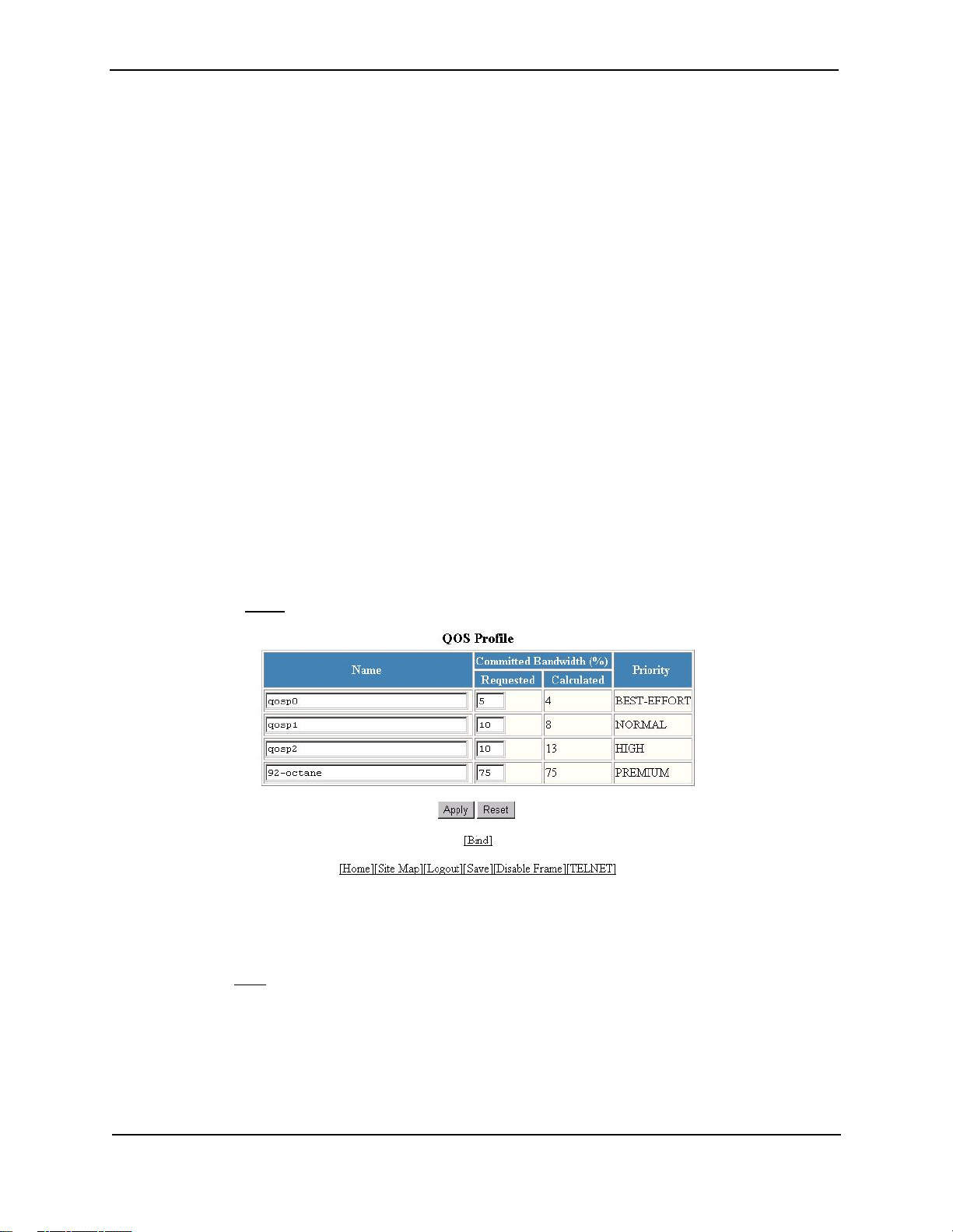
Advanced Configuration and Management Guide
Configuring the Queues
Each of the four queues has the following configurable parameters:
• The queue name
• The minimum percentage of a port’s outbound bandwidth guaranteed to the queue.
Renaming the Queues
The default queue names are qosp3, qosp2, qosp1, and qosp0. You can change one or more of the names if
desired. To do so, use one of the following methods.
USING THE CLI
To rename queue qosp3 (the premium queue) to “92-octane”, enter the following commands:
HP9300(config)# qos name qosp3 92-octane
HP9300(config)# write memory
Syntax: qos name <old-name> <new-name>
The <old-name> parameter specifies the name of the queue before the change.
The <new-name> parameter specifies the new name of the queue. You can specify an alphanumeric string up to
32 characters long.
USING THE WEB MANAGEMENT INTERFACE
1. Log on to the device using a valid user name and password for read-write access. The System configuration
dialog is displayed.
2. Click on the plus sign next to Configure in the tree view to expand the list of configuration options.
3. Click on the plus sign next to QoS in the tree view to expand the list of QoS option links.
4. Click on the Profile
5. Edit the strings name the Name fields for the queue(s) you want to rename. In this example, the premium
queue is renamed from “qosp3” to “92-octane”.
6. Click the Apply button to save the change to the device’s running-config file.
7. Select the Save
change to the startup-config file on the device’s flash memory.
link to display the QoS Profile configuration panel, as shown in the following figure.
link at the bottom of the dialog, then select Yes when prompted to save the configuration
2 - 4
Page 30

Quality of Service (QoS)
Changing the Minimum Bandwidth Percentages of the Queues
If you are using the weighted fair queuing mechanism instead of the strict mechanism, you can change the
weights for each queue by changing the minimum percentage of bandwidth you want each queue to guarantee for
its traffic.
By default, the four QoS queues receive the following minimum guaranteed percentages of a port’s total
bandwidth.
Queue Default Minimum Percentage of Bandwidth
qosp3 80%
qosp2 15%
qosp1 3.3%
qosp0 1.7%
NOTE: The percentages are guaranteed minimum bandwidth percentages. Thus, they apply when a port is fully
utilized. When a port is not fully utilized, it is possible for queues to receive more than the configured percentage
of bandwidth. You cannot specify a maximum bandwidth percentage for a queue. Any queue can get more than
its committed share when other queues are idle.
When the queuing method is weighted fair queuing, the software internally translates the percentages into
weights. The weight associated with each queue controls how many packets are processed for the queue at a
given stage of a cycle through the weighted fair queuing algorithm.
For example, the default percentages shown above translate into the following weights.
Queue Default Minimum Percentage
of Bandwidth
qosp3 80% 4
qosp2 15% 3
qosp1 3.3% 2
qosp0 1.7% 1
A queue’s weight specifies how many packets are sent from the queue each time the queue is serviced. Thus,
when the default bandwidth percentages are used, four packets are sent from queue qosp3 each time the queue
is serviced, while three packets are sent from queue qosp2 each time it is serviced, and so on. The queuing
mechanism interleaves the queues during the cycle so that queue qosp3 is serviced after each visit to any other
queue. For example, using the default percentages (and thus the default weights), queue qosp3 receives 12 visits
for every one visit to queue qosp0.
Queue Weight
2 - 5
Page 31

Advanced Configuration and Management Guide
The following table shows one full queue cycle using the default bandwidth percentages.
qosp3
bandwidth % = 80
weight = 4
Total visits Total
packets
1 1
2 2
3 2 1 3
4 6 1
5 0 4
6 4 5
7 8 2 6
8 2 1 2
9 6 7
10 40 8
11 44 3 9
12 48 1 1
4
8
1
1
2
2
2
3
3
Total visits Total
qosp2
bandwidth % = 15
weight = 3
packets
qosp1
bandwidth % = 3.3
weight = 2
Total visits Total
packets
qosp0
bandwidth % = 1.7
weight = 1
Total visits Total
packets
2 - 6
Page 32

Figure 2.1 illustrates a cycle through the queues.
q0
q2
q3
q3
q3
q3
q3
q3
q3
q3
q2
q3
q3
Quality of Service (QoS)
q3
q3
q2
q3
q3
q3
q3
q2
q2
q3
q3
q3
q3
q3
q3
q3
q3
q1
q3
q3
q3
q3
q2
Begin here
q3
q3
q3
q3
q2
q3
q3
q3
q3
q2
q3
q3
q3
q3
q3
q3
q3
q3
q2
q1
q3
q3
q3
q3
Queue 3: weight=4, minimum percentage=80%
Queue 2: weight=3, minimum percentage=15%
Queue 1: weight=2, minimum percentage=3.3%
Queue 0: weight=1, minimum percentage=1.7%
Figure 2.1 Example of a QoS cycle using the default weights
If you change the percentages for the queues, the software changes the weights, which changes the number of
visits a queue receives during a full queue cycle and also the number of packets sent from each queue during
each visit. For example, if you change the percentages so that queue qosp3 receives a weight of 5, then the
system processes five packets in that queue during each visit to the queue.
NOTE: The weighted fair queuing method is based on packet-level scheduling. As a result, a queue’s bandwidth
percentage does not necessarily reflect the exact bandwidth share the queue receives. This is due to the effects
of variable size packets.
2 - 7
Page 33

Advanced Configuration and Management Guide
USING THE CLI
To change the minimum guaranteed bandwidth percentages of the queues, enter commands such as the
following. Note that this example uses the default queue names.
HP9300(config)# qos profile qosp3 75 qosp2 10 qosp1 10 qosp0 5
Profile qosp3 : PREMIUM bandwidth requested 75% calculated 75%
Profile qosp2 : HIGH bandwidth requested 10% calculated 13%
Profile qosp1 : NORMAL bandwidth requested 10% calculated 8%
Profile qosp0 : BEST-EFFORT bandwidth requested 5% calculated 4%
HP9300(config)# write memory
Notice that the CLI displays the percentages you request and the percentages the device can provide based on
your request. The values are not always the same, as explained below.
Syntax: [no] qos profile <queue> <percentage> <queue> <percentage> <queue> <percentage>
<queue> <percentage>
Each <queue> parameter specifies the name of a queue. You can specify the queues in any order on the
command line, but you must specify each queue.
The <percentage> parameter specifies a number for the percentage of the device’s outbound bandwidth that are
allocating to the queue.
NOTE: The percentages you enter must equal 100. Also, the percentage for the premium queue (the highest
priority queue) must be at least 50.
If you enter percentages that are less than the minimum percentages supported for a queue, the CLI recalculates
the percentages to fall within the supported minimums. Here is an example. In this example, the values entered
for all but the best-effort queue (the lowest priority queue) are much lower than the minimum values supported for
those queues.
HP9300(config)# qos qosp3 1 qosp2 1 qosp1 2 qosp0 96
Warning - qosp3 bandwidth should be at least 50%
bandwidth scheduling mechanism: weighted priority
Profile qosp3 : PREMIUM bandwidth requested 1% calculated 50%
Profile qosp2 : HIGH bandwidth requested 1% calculated 25%
Profile qosp1 : NORMAL bandwidth requested 2% calculated 13%
Profile qosp0 : BEST-EFFORT bandwidth requested 96% calculated 12%
This example shows the warning message that is displayed if you enter a value that is less than 50% for the
premium queue. This example also shows the recalculations performed by the CLI. The CLI must normalize the
values because the weighted fair queuing algorithm and queue hardware require specific minimum bandwidth
allocations. You cannot configure the hardware to exceed the weighted fair queuing limitations.
The CLI normalizes the percentages you enter by increasing the percentages as needed for queues that have
less than the minimum percentage, converting the percentages to weights (which the weighted fair queuing
algorithm uses), and applying the following equations to calculate the percentages:
qosp3 = w3 / (w3 + 1)
qosp2 = (1 – qosp3) * w2 / (w2 + 1)
qosp1 = (1 – qosp3 – qosp2) * w1 / (w1 + 1)
qosp0 = 1 – qosp3 – qosp2 – qosp1
The value “w” stands for “weight”. Thus, these calculations determine the weights that the weighted fair queuing
algorithm will use for each queue.
For results that do not differ widely from the percentages you enter, enter successively lower percentages for each
queue, beginning with the premium queue. If you enter a higher percentage for a particular queue than you enter
for a higher queue, the normalized results can vary widely from the percentages you enter.
2 - 8
Page 34

Quality of Service (QoS)
USING THE WEB MANAGEMENT INTERFACE
1. Log on to the device using a valid user name and password for read-write access. The System configuration
dialog is displayed.
2. Click on the plus sign next to Configure in the tree view to expand the list of configuration options.
3. Click on the plus sign next to QoS in the tree view to expand the list of QoS option links.
4. Click on the Profile
5. Edit the values in the Requested fields for the queue(s) you want to change. In this example, the following
minimum bandwidths are requested:
• qosp0 – 5%
• qosp1 – 10%
• qosp2 – 10%
• 92-octane – 75%
link to display the QoS Profile configuration panel, as shown in the following figure.
NOTE: The percentages you enter must equal 100. Also, the percentage for the premium queue (the
highest priority queue) must be at least 50.
6. Click the Apply button to save the changes to the device’s running-config file. Notice that the device
calculates the minimum bandwidth percentages that can be allocated to each of the queues based on your
percentage requests, and displays the actual percentages in the Calculated column. Here is an example.
2 - 9
Page 35

Advanced Configuration and Management Guide
7. Select the Save
change to the startup-config file on the device’s flash memory.
link at the bottom of the dialog, then select Yes when prompted to save the configuration
Resetting the Minimum Bandwidth Percentages to Their Defaults
You can use either of the following CLI commands to reset the QoS queues to their default bandwidth percentages
(and therefore to their default weights).
USING THE CLI
Enter either of the following commands at the global CONFIG level:
• qos mechanism weighted
• no qos profile
USING THE WEB MANAGEMENT INTERFACE
You cannot reset the queue profiles to the default bandwidth percentages using the Web management interface.
Displaying the QoS Profile Configuration
To display the QoS settings, use either of the following methods.
USING THE CLI
To display the QoS settings for all the queues, enter the following command from any level of the CLI:
HP9300(config)# show qos-profiles all
bandwidth scheduling mechanism: weighted priority
Profile qosp3 : PREMIUM bandwidth requested 75% calculated 75%
Profile qosp2 : HIGH bandwidth requested 10% calculated 13%
Profile qosp1 : NORMAL bandwidth requested 10% calculated 8%
Profile qosp0 : BEST-EFFORT bandwidth requested 5% calculated 4%
Syntax: show qos-profiles all | <name>
The all parameter displays the settings for all four queues. The <name> parameter displays the settings for the
specified queue.
USING THE WEB MANAGEMENT INTERFACE
1. Log on to the device using a valid user name and password for read-write access. The System configuration
dialog is displayed.
2. Click on the plus sign next to Configure in the tree view to expand the list of configuration options.
3. Click on the plus sign next to QoS in the tree view to expand the list of QoS option links.
4. Click on the Profile
link to display the QoS Profile configuration panel.
2 - 10
Page 36

Quality of Service (QoS)
Assigning QoS Priorities to Traffic
By default, traffic of the following categories is forwarded using the best-effort queue (qosp0):
• Incoming port (sometimes called the ingress port)
• Port-based VLAN membership
• Static destination MAC entry
• Layer 3 and Layer 4 information (IP and TCP/UDP source and destination information)
• AppleTalk socket
NOTE: Tagged VLAN traffic is placed in a queue corresponding to the 802.1p priority in the tag by default. Thus,
if a tagged packet contains priority 7 in the tag (corresponding to the premium queue), the device places this
packet in the premium queue of the packet’s outbound port. You can change or remove the effect of the 802.1p
priority in the tags by reassigning the priority levels to different queues. See “Reassigning 802.1p Priorities to
Different Queues” on page 2-14.
Although it is possible for a packet to qualify for an adjusted QoS priority based on more than one of the criteria
above, the system always gives a packet the highest priority for which it qualifies. Thus, if a packet is entitled to
the premium queue because of its IP source and destination addresses, but is entitled only to the high queue
because of its incoming port, the system places the packet in the premium queue on the outgoing port.
When you apply a QoS priority to one of the items listed above, you specify a number from
0 – 7. The number specifies the IEEE 802.1 equivalent to one of the four HP QoS queues. The numbers
correspond to the queues as follows.
Priority Level Queue
6, 7 qosp3
4, 5 qosp2
2, 3 qosp1
0, 1 qosp0
The following sections describe how to change the priority for each of the items listed above.
Changing a Port’s Priority
To change a port’s QoS priority, use one of the following methods. The priority applies to outbound traffic on the
port.
USING THE CLI
To change the QoS priority of port 1/1 to the high queue (qosp2), enter the following commands:
HP9300(config)# interface ethernet 1/1
HP9300(config-if-1/1)# priority 5
HP9300(config-if-1/1)# write memory
Syntax: [no] priority <num>
The <num> parameter can be from 0 – 7 and specifies the IEEE 802.1 equivalent to one of the four QoS queues.
2 - 11
Page 37

Advanced Configuration and Management Guide
USING THE WEB MANAGEMENT INTERFACE
1. Log on to the device using a valid user name and password for read-write access. The System configuration
dialog is displayed.
2. Click on the Port
3. Scroll down to the port for which you want to change the QoS level, then click on the Modify button to the right
of the port information to display the Port configuration panel, as shown in the following example.
4. Select a QoS level from 0 – 7 from the QoS field’s pulldown menu.
5. Click the Apply button to save the change to the device’s running-config file.
link to display the Port table.
6. Select the Save
change to the startup-config file on the device’s flash memory.
link at the bottom of the dialog, then select Yes when prompted to save the configuration
Changing a Layer 2 Port-Based VLAN’s Priority
By default, VLANs have priority 0 (the best effort queue, qosp0). To change a port-based VLAN’s QoS priority,
use one of the following methods. The priority applies to outbound traffic on ports in the VLAN.
NOTE: Tagged packets also contain a priority value in the 802.1q tag. If you use the default priority for a VLAN, a
tagged packet that exits on that VLAN can be placed into a higher priority queue based on the port priority, the
priority in the 802.1q tag, and so on. If you do not want the device to make priority decisions based on 802.1q
tags, you can change the priority for 802.1q tags on a VLAN basis. See “Reassigning 802.1p Priorities to Different
Queues” on page 2-14”.
USING THE CLI
To change the QoS priority of port-based VLAN 20 to the premium queue (qosp3), enter the following commands:
HP9300(config)# vlan 20
HP9300(config-vlan-20)# priority 7
HP9300(config-vlan-20)# write memory
Syntax: [no] priority <num>
The <num> parameter can be from 0 – 7 and specifies the IEEE 802.1 equivalent to one of the four QoS queues.
2 - 12
Page 38

Quality of Service (QoS)
USING THE WEB MANAGEMENT INTERFACE
1. Log on to the device using a valid user name and password for read-write access. The System configuration
dialog is displayed.
2. Click on the plus sign next to Configure in the tree view to expand the list of configuration options.
3. Click on the plus sign next to VLAN in the tree view to expand the list of VLAN option links.
4. Click on the Port
• If you are adding a new port-based VLAN, click on the Add Port VLAN
configuration panel, as shown in the following example.
• If you are modifying an existing port-based VLAN, click on the Modify button to the right of the row
describing the VLAN to display the Port VLAN configuration panel, as shown in the following example.
5. Select a QoS level from 0 – 7 from the QoS field’s pulldown menu.
6. If you are adding a new VLAN, click the Select Port Members button to display the Port Members dialog, as
shown in the following example.
link to display the Port VLAN panel.
link to display the Port VLAN
7. Select the ports you are placing in the VLAN. To select a row, click on the checkbox next to the row number,
then click on the Select Row button.
8. When you finish selecting the ports, click on the Continue button to return to the Port VLAN configuration
dialog.
9. Click the Add button (to add a new VLAN) or the Modify button (if you are modifying an existing VLAN) to
save the change to the device’s running-config file.
10. Select the Save
change to the startup-config file on the device’s flash memory.
link at the bottom of the dialog, then select Yes when prompted to save the configuration
2 - 13
Page 39

Advanced Configuration and Management Guide
Reassigning 802.1p Priorities to Different Queues
Tagged priority applies to tagged packets that come in from tagged ports. These packets have a tag in the header
that specifies the packet’s VLAN ID and its 802.1p priority tag value, which is 3 bits long.
By default, an HP device interprets the prioritization information in the 3-bit priority tag as follows.
Priority Level Queue
6, 7 qosp3
4, 5 qosp2
2, 3 qosp1
0, 1 qosp0
This is the HP default interpretation for the eight prioritization values in every context (VLAN, static MAC entry, IP
access policy, and so on). If the VLAN for the packet uses the default priority (0, equal to the qosp0 queue), then
the HP device uses the priority information in the packet to assign the packet to a queue on its incoming port.
However, if the VLAN or the incoming port itself has a higher priority than the packet’s 802.1p priority, the HP
device uses the VLAN priority or incoming port priority, whichever is higher.
You can specify how the HP device interprets the 3-bit priority information by reassigning the priority levels to
other queues. For example, if you want the device to disregard the 802.1p priority and instead assign the priority
based on other items (VLAN, port, and so on), configure the device to set all the 802.1p priorities to the best-effort
queue (qosp0). If a tagged packet’s 802.1p priority level is always in the qosp0 queue, then the packet’s outbound
queue is affected by other items such as incoming port, VLAN, and so on.
To reassign the priorities to different queues, use either of the following methods.
USING THE CLI
To reassign all 802.1p priority levels 2 – 7 to the best-effort queue (qosp0), enter the following commands:
HP9300(config)# qos tagged-priority 2 qosp0
HP9300(config)# qos tagged-priority 3 qosp0
HP9300(config)# qos tagged-priority 4 qosp0
HP9300(config)# qos tagged-priority 5 qosp0
HP9300(config)# qos tagged-priority 6 qosp0
HP9300(config)# qos tagged-priority 7 qosp0
HP9300(config)# write memory
Syntax: [no] qos tagged-priority <num> <queue>
The <num> parameter can be from 0 – 7 and specifies the IEEE 802.1 equivalent to one of the four QoS queues.
The <queue> parameter specifies the queue to which you are reassigning the priority level. You must specify one
of the named queues. The default names are qosp3, qosp2, qosp1, and qosp0. The example above reassigns
the 802.1p levels to queue qosp0. (There is no need to reassign levels 0 and 1 in this case, because they are
already assigned to qosp0 by default.)
USING THE WEB MANAGEMENT INTERFACE
1. Log on to the device using a valid user name and password for read-write access. The System configuration
dialog is displayed.
2. Click on the plus sign next to Configure in the tree view to expand the list of configuration options.
3. Click on the plus sign next to QoS in the tree view to expand the list of QoS option links.
2 - 14
Page 40

Quality of Service (QoS)
4. Click on the Bind
following figure.
5. For each priority level, select the QoS queue to which you want to reassign the profile by selecting the queue
name from the Profile field’s pulldown list. For example, to reassign priority 7 to QoS queue qosp0, select
qosp0 from the Profile Name field’s pulldown list in the row for priority 7.
6. Click the Apply button to save the change to the device’s running-config file.
link to display the QoS 802.1p to QoS Profile Binding configuration panel, as shown in the
7. Select the Save
change to the startup-config file on the device’s flash memory.
link at the bottom of the dialog, then select Yes when prompted to save the configuration
Displaying the Queue Assignments for the 802.1p Priorities
To display the queues to which the 802.1p priorities are assigned, use either of the following methods.
USING THE CLI
To display the queue assignments for all the priorities, enter the following command at any level of the CLI:
HP9300(config)# show priority-mapping all
802.1p priority 0 mapped to qos profile qosp0
802.1p priority 1 mapped to qos profile qosp0
802.1p priority 2 mapped to qos profile qosp1
802.1p priority 3 mapped to qos profile qosp1
802.1p priority 4 mapped to qos profile qosp2
802.1p priority 5 mapped to qos profile qosp2
802.1p priority 6 mapped to qos profile qosp3
802.1p priority 7 mapped to qos profile qosp3
In this example, the priorities still have their default queue assignments.
Syntax: show priority-mapping all | <num>
The all parameter displays the queue assignments for all the priorities. Alternatively, you can display the
assignment for a particular level by specifying the level number, as shown in the following example.
HP9300(config)# show priority-mapping 1
802.1p priority 1 mapped to qos profile qosp0
2 - 15
Page 41

Advanced Configuration and Management Guide
USING THE WEB MANAGEMENT INTERFACE
1. Log on to the device using a valid user name and password for read-write access. The System configuration
dialog is displayed.
2. Click on the plus sign next to Configure in the tree view to expand the list of configuration options.
3. Click on the plus sign next to QoS in the tree view to expand the list of QoS option links.
4. Click on the Bind
assignments are listed for each of the eight priority levels.
link to display the QoS 802.1p to QoS Profile Binding configuration panel. The queue
Assigning Static MAC Entries to Priority Queues
By default, all MAC entries are in the best effort queue (qosp0). When you configure a static MAC entry, you can
assign the entry to a higher QoS level using either of the following methods.
USING THE CLI
To configure a static MAC entry and assign the entry to the premium queue, enter commands such as the
following:
HP9300(config)# vlan 9
HP9300(config-vlan-9)# static-mac-address 1145.1163.67FF e12 priority 7
HP9300(config)# write memory
Syntax: [no] static-mac-address <mac-addr> ethernet <portnum> [priority <num>]
[host-type | router-type]
The <num> parameter can be from 0 – 7 and specifies the IEEE 802.1 equivalent to one of the four QoS queues.
NOTE: On a routing switch, the static-mac-address command is at the port VLAN configuration level. On an HP
6208M-SX, the static-mac-address command is at the global CONFIG level.
USING THE WEB MANAGEMENT INTERFACE
1. Log on to the device using a valid user name and password for read-write access. The System configuration
dialog is displayed.
2. Click on the plus sign next to Configure in the tree view to expand the list of configuration options.
3. Select the Static Station
• If the system already contains static MAC addresses and you are adding a new static MAC address, click
on the Add Static Station link to display the Static Station Table configuration panel, as shown in the
following example.
• If you are modifying an existing static MAC address, click on the Modify button to the right of the row
describing the static MAC address to display the Static Station Table configuration panel, as shown in the
following example.
link to display the Static Station Table.
2 - 16
Page 42

Quality of Service (QoS)
4. Enter or edit the MAC address, if needed. Specify the address in the following format:
xx-xx-xx-xx-xx-xx.
5. Change the VLAN number if needed by editing the value in the VLAN ID field.
6. Select the port number from the Slot (for Chassis devices) and Port pulldown lists.
7. Select a QoS level from 0 – 7 from the QoS field’s pulldown menu.
8. Click the Add button (to add a new static MAC entry) or the Modify button (if you are modifying an existing
entry) to save the change to the device’s running-config file.
9. Click the Apply button to save the change to the device’s running-config file.
10. Select the Save
change to the startup-config file on the device’s flash memory.
link at the bottom of the dialog, then select Yes when prompted to save the configuration
Assigning IP and Layer 4 Sessions to Priority Queues
You can assign specific traffic flows to queues by configuring IP access policies. IP access policies allow you to
assign flows to priority queues based on any combination of the following criteria:
• Source IP address
• Destination IP address
• Layer 4 type (TCP or UDP)
• TCP or UDP port number
You configure IP access policies globally, then apply them to specific ports. QoS policies apply only to outbound
traffic, so you must apply the QoS polices to a port’s outbound direction instead of the port’s inbound direction.
To configure an IP access policy for assigning a traffic flow to a priority queue, use either of the following methods.
USING THE CLI
The CLI syntax differs between routing switches and switches. Examples and syntax are shown for both types of
devices.
Routing Switch Syntax
To assign a priority of 4 to all HTTP traffic on port 3/12 on an HP 9304M or HP 9308M routing switch, enter the
following:
HP9300(config)# ip access-policy 1 priority 4 any any tcp eq http
HP9300(config)# int e 3/12
HP9300(config-if-3/12)# ip access-policy-group out 1
Here is the syntax for routing switches.
Syntax: [no] ip access-policy <num> priority <0-7> <ip-addr> <ip-mask> | any
<ip-addr> <ip-mask> | any icmp | igmp | igrp | ospf | tcp | udp | <num> [<operator> [<tcp/udp-port-num>]]
Syntax: ip access-policy-group in | out <policy-list>
The <num> parameter is the policy number.
The priority <0-7> parameter specifies the QoS priority level. The default is 0 (best effort, qosp0). The highest
priority is 7 (premium, qosp3).
The <ip-addr> <ip-mask> | any <ip-addr> <ip-mask> | any parameters specify the source and destination IP
addresses. If you specify a particular IP address, you also need to specify the mask for that address. If you
specify any to apply the policy to all source or destination addresses, you do not need to specify any again for the
mask. Make sure you specify a separate address and mask or any for the source and destination address.
The icmp | igmp | igrp | ospf | tcp | udp | <num> parameter specifies the Layer 4 port to which you are applying
the policy. If you specify tcp or udp, you also can use the optional <operator> and <tcp/udp-port-num>
parameters to fine-tune the policy to apply to specific TCP or UDP ports.
2 - 17
Page 43

Advanced Configuration and Management Guide
The <operator> parameter applies only if you use the tcp or udp parameter above. Use the <operator>
parameter to specify the comparison condition for the specific TCP or UDP ports. For example, if you are
configuring QoS for HTTP, specify tcp eq http. You can enter one of the following operators:
• eq – The policy applies to the TCP or UDP port name or number you enter after eq.
• gt – The policy applies to TCP or UDP port numbers greater than the port number or the numeric equivalent
of the port name you enter after gt.
• lt – The policy applies to TCP or UDP port numbers that are less than the port number or the numeric
equivalent of the port name you enter after lt.
• neq – The policy applies to all TCP or UDP port numbers except the port number or port name you enter after
neq.
• range – The policy applies to all TCP or UDP port numbers that are between the first TCP or UDP port name
or number and the second one you enter following the range parameter. The range includes the port names
or numbers you enter. For example, to apply the policy to all ports between and including 23 (Telnet) and 53
(DNS), enter the following: range 23 53. The first port number in the range must be lower than the last
number in the range.
• established – This operator applies only to TCP packets. If you use this operator, the QoS policy applies to
TCP packets that have the ACK (Acknowledgment) or RST (Reset) bits set on (set to “1”) in the Control Bits
field of the TCP packet header. Thus, the policy applies only to established TCP sessions, not to new
sessions. See Section 3.1, “Header Format”, in RFC 793 for information about this field.
The in parameter applies the policy to packets received in the port.
The out parameter applies the policy to packets sent on the port.
NOTE: To apply the policy to traffic in both directions, enter two ip access-policy-group commands, one
specifying the in parameter, and the other specifying the out parameter.
The <policy-list> parameter is a list of policy IDs.
NOTE: The device applies the policies in the order you list them, so make sure you order them in such a away
that you receive the results you expect. Once a packet matches a policy, the device takes the action specified in
that policy and stops comparing the packet to the policies in the list.
2 - 18
Page 44

Quality of Service (QoS)
Figure 2.2 and Figure 2.3 show the CLI syntax for configuring a Layer 4 QoS policy on an HP routing switch.
ip access-policy
icmp
igmp
igrp
ospf
<num>
tcp
<num> priority <num> <src-ip-addr> <ip-mask>|any <dst-ip-addr> <ip-mask>|any
<CR>
<CR>
<CR>
<CR>
<CR>
eq
gt
lt
neq
range
bgp | dns |
ftp | http |
imap4 | ldap |
nntp | pop2 |
pop3 | smtp |
ssl | telnet |
<num>
bgp | dns |
ftp | http |
imap4 | ldap |
nntp | pop2 |
pop3 | smtp |
ssl | telnet |
<num>
<CR>
bgp | dns |
ftp | http |
imap4 | ldap |
nntp | pop2 |
pop3 | smtp |
ssl | telnet |
<num>
<CR>
udp
eq
established
<CR>
gt
lt
neq
range
<CR>
see the next page...
bgp | dns |
ftp | http |
imap4 | ldap |
nntp | pop2 |
pop3 | smtp |
ssl | telnet |
<num>
bgp | dns |
ftp | http |
imap4 | ldap |
nntp | pop2 |
pop3 | smtp |
ssl | telnet |
<num>
<CR>
bgp | dns |
ftp | http |
imap4 | ldap |
nntp | pop2 |
pop3 | smtp |
ssl | telnet |
<num>
Figure 2.2 QoS IP policy syntax for an HP routing switch (1 of 2)
<CR>
2 - 19
Page 45

Advanced Configuration and Management Guide
continued from previous page
udp
ip access-policy-group
eq
gt
lt
neq
range
bootpc | bootps |
dns | tftp |
ntp | radius |
radius-old | rip |
snmp | snmp-trap |
<num>
bootpc | bootps |
dns | tftp |
ntp | radius |
radius-old | rip |
snmp | snmp-trap |
<num>
in
out
<CR>
bootpc | bootps |
dns | tftp |
ntp | radius |
radius-old | rip |
snmp | snmp-trap |
<num>
<policy-list>
<CR>
<CR>
Figure 2.3 QoS IP policy syntax for an HP routing switch (2 of 2)
Switch Syntax
To assign a priority of 7 to FTP traffic on all ports on an HP 6208M-SX switch, enter the following commands:
HP6208(config)# ip policy 1 7 tcp ftp global
HP6208(config)# write memory
To assign a priority of 7 to HTTP traffic on ports 1 and 2 only, enter the following commands:
HP6208(config)# ip policy 2 7 tcp http local
HP6208(config)# int ethernet 1
HP6208(config-if-1)# ip-policy 2
HP6208(config-if-1)# int ethernet 2
HP6208(config-if-2)# ip-policy 2
HP6208(config)# write memory
Syntax: policy <num> priority <0-7> tcp | udp <tcp/udp-port-num> global | local
[no] ip-policy <num>
The <num> parameter is the policy number.
The priority <0-7> parameter specifies the QoS priority level. The default is 0 (best effort queue, qosp0). The
highest priority is 7 (premium, qosp3).
The tcp | udp <tcp/udp-port-num> parameter specifies the TCP or UDP port to which you are applying the policy.
The global and local parameters specify the scope of the policy:
• If you specify global, the policy applies to all ports.
• If you specify local, the policy will apply to the ports you specify. Use the following command on the Interface
level of the CLI to apply the policy to a port: ip-policy <num>
2 - 20
Page 46

Quality of Service (QoS)
Figure 2.4 shows the CLI syntax for configuring a QoS policy on an HP switch. The value “<CR>” means
“carriage return”, also known as the Enter key.
ip policy
<num> priority
<num>
tcp
udp
bgp
dns
ftp
http
imap4
ldap
nntp
pop2
pop3
smtp
ssl
telnet
<num>
bootpc
bootps
dns
tftp
ntp
radius
radius-old
rip
snmp
snmp-trap
<num>
global
local
global
local
<CR>
<CR>
ip-policy
<num>
<CR>
Figure 2.4 QoS IP policy syntax for an HP switch
NOTE: The ip policy command allows you to configure global or local QoS policies. Use the ip-policy command
(note the difference between “ip policy” and “ip-policy”) at the Interface level of the CLI to apply a local policy to
a specific interface.
USING THE WEB MANAGEMENT INTERFACE
The Web management options for assigning QoS priorities to traffic flows differ between routing switches and
switches. Examples are shown for both types of devices.
2 - 21
Page 47

Advanced Configuration and Management Guide
Routing Switch
To assign a priority of 4 to all HTTP traffic on port 3/12 on an HP 9304M or HP 9308M routing switch, perform the
following steps:
1. Log on to the device using a valid user name and password for read-write access. The System configuration
dialog is displayed.
2. Click on the plus sign next to Configure in the tree view to expand the list of configuration options.
3. Click on the plus sign next to IP in the tree view to expand the list of IP option links.
4. Click on the Access Policy link to display the IP Access Policy panel.
• If the system already contains IP access policies and you are adding a new one, click on the Add IP
Access Policy link to display the IP Access Policy configuration panel, as shown in the following
example.
• If you are modifying an existing IP access policy, click on the Modify button to the right of the row
describing the IP access policy to display the IP Access Policy configuration panel, as shown in the
following example.
5. Enter the ID for the policy in the ID field.
6. Select the QoS radio button next to Action.
7. Select a QoS level from 0 – 7 from the QoS field’s pulldown menu. In this example, select 4.
8. Enter the source IP address and network mask in the Source Address and Source Mask fields. To specify
“any” for a field, leave all four zeros in the field. In this example, leave the zeros.
9. Enter the destination IP address and network mask in the Destination Address and Destination Mask fields.
To specify “any” for a field, leave all four zeroes in the field. In this example, leave the zeros.
10. If you want the policy to apply only to packets containing specific types of Layer 4 traffic, enter the protocol in
the Protocol field. You can enter the protocol’s Layer 4 port number or one of the following well-known
names:
• icmp
• igmp
• igrp
2 - 22
Page 48

Quality of Service (QoS)
• ospf
• tcp
• udp
In this example, enter tcp.
11. If you entered tcp or udp, you also can select one of the following comparison operators from the Operator
field.
• Equal – The policy applies to the TCP or UDP port name or number you enter in the TCP/UDP port field.
In this example, select Equal.
• Greater – The policy applies to TCP or UDP port numbers greater than the port number or the numeric
equivalent of the port name you enter in the TCP/UDP port field.
• Less – The policy applies to TCP or UDP port numbers that are less than the port number or the numeric
equivalent of the port name you enter in the TCP/UDP port field.
• Not Equal – The policy applies to all TCP or UDP port numbers except the port number or port name you
enter in the TCP/UDP port field.
12. If you entered tcp or udp in the Protocol field, enter the TCP or UDP port number in the TCP/UDP port field.
In this example, enter 80 (the well-known port for HTTP).
13. If you entered tcp in the Protocol field and you want the policy to apply to TCP sessions that are already in
effect, click on the checkbox next to Established. If you select this option, the QoS policy applies to TCP
packets that have the ACK (Acknowledgment) or RST (Reset) bits set on (set to “1”) in the Control Bits field of
the TCP packet header. Thus, the policy applies only to established TCP sessions, not to new sessions. See
Section 3.1, “Header Format”, in RFC 793 for information about this field.
NOTE: This option applies only to destination TCP ports, not to source TCP ports.
14. Click the Add button (to add a new policy) or the Modify button (if you are modifying an existing policy) to save
the policy to the device’s running-config file.
15. Select the Access Policy Group link to display the Access Policy Group panel.
• If the system already contains IP access policy groups and you are adding a new one, click on the Add IP
Access Policy Group link to display the IP Access Policy Group configuration panel, as shown in the
following example.
• If you are modifying an existing IP access policy, click on the Modify button to the right of the row
describing the IP access policy group to display the IP Access Policy Group configuration panel, as
shown in the following example.
16. Select the port number from the Slot (for Chassis devices) and Port pulldown lists. In this example, select 3/
12.
2 - 23
Page 49

Advanced Configuration and Management Guide
17. Click the checkbox next to In Filter, Out Filter, or next to both options to indicate the traffic direction to which
you are applying the policy.
• The In Filter option applies the policy to packets received in the port.
• The Out Filter option applies the policy to packets sent on the port.
• If you select both, the policy applies to traffic in both directions.
In this example, select Out Filter.
18. Enter the policy IDs in the Filter ID List field.
NOTE: The device applies the policies in the order you list them, so make sure you order them in such a
way that you receive the results you expect. Once a packet matches a policy, the device takes the action
specified in that policy and stops comparing the packet to the policies in the list.
19. Click the Add button to apply the change to the device’s running-config file.
20. Select the Save link at the bottom of the dialog, then select Yes when prompted to save the configuration
change to the startup-config file on the device’s flash memory.
NOTE: You also can access the dialog for saving configuration changes by clicking on Command in the tree
view, then clicking on
Save to Flash.
Switch
To assign a priority of 7 to FTP traffic on all ports on an HP 6208M-SX switch, perform the following steps:
1. Log on to the device using a valid user name and password for read-write access. The System configuration
dialog is displayed.
2. Select the Layer 4 QoS link to display the QoS panel.
3. Enter the ID for the policy in the ID field.
4. Select the Switch or Port radio button next to Scope to indicate whether the policy applies globally or only to
certain ports.
5. Select a QoS level from 0 – 7 from the QoS field’s pulldown menu. In this example, select 7.
6. Select the UDP or TCP radio button next to Protocol to specify the type of traffic to which the QoS policy
applies.
7. Select a well-known TCP or UDP port name (depending on whether you selected TCP or UDP) from the TCP/
UDP Port field’s pulldown list. To enter a port number instead, click on the User Define button to change the
field into an entry field, then enter the port number. For this example, select FTP.
8. Click the Add button to apply the change to the device’s running-config file.
9. If you selected Port in step 4, click on Port QoS to display the Port QoS panel. Otherwise, go to step 13.
10. Select the port number from the Slot (for Chassis devices) and Port pulldown lists.
11. Enter the policy IDs in the QoS ID List field.
NOTE: The device applies the policies in the order you list them, so make sure you order them in such a
away that you receive the results you expect. Once a packet matches a policy, the device takes the action
specified in that policy and stops comparing the packet to the policies in the list.
12. Click the Add button to apply the change to the device’s running-config file.
13. Select the Save
change to the startup-config file on the device’s flash memory.
2 - 24
link at the bottom of the dialog, then select Yes when prompted to save the configuration
Page 50

Quality of Service (QoS)
Assigning AppleTalk Sockets to Priority Queues
By default, all AppleTalk sockets are in the best effort queue (qosp0). To assign an AppleTalk socket to a higher
priority queue, use either of the following methods.
USING THE CLI
To assign socket 123 to the premium queue, enter the following commands:
HP9300(config)# appletalk qos socket 123 priority 7
HP9300(config)# write memory
Syntax: [no] appletalk qos socket <num> priority <num>
The first <num> parameter specifies the socket number.
The second <num> parameter can be from 0 – 7 and specifies the IEEE 802.1 equivalent to one of the four QoS
queues.
USING THE WEB MANAGEMENT INTERFACE
1. Log on to the device using a valid user name and password for read-write access. The System configuration
dialog is displayed.
2. If AppleTalk is not already enabled, enable it by selecting the Enable radio button next to AppleTalk, then
clicking Apply.
3. Click on the plus sign next to Configure in the tree view to expand the list of configuration options.
4. Click on the plus sign next to AppleTalk in the tree view to expand the list of AppleTalk option links.
5. Click on the Socket QoS
6. Edit the socket number in the Socket field if needed.
7. Select a QoS level from 0 – 7 from the QoS field’s pulldown menu.
8. Click on the Apply button to apply the new QoS setting to the socket number specified in the Socket field or
click on the Apply To All Sockets button to apply the new QoS setting to all AppleTalk sockets.
9. Select the Save
change to the startup-config file on the device’s flash memory.
link at the bottom of the dialog, then select Yes when prompted to save the configuration
link to display the AppleTalk Socket QoS panel, as shown in the following example.
2 - 25
Page 51

Advanced Configuration and Management Guide
Configuring a Utilization List for an Uplink Port
You can configure uplink utilization lists that display the percentage of a given uplink port’s bandwidth that is used
by a specific list of downlink ports. The percentages are based on 30-second intervals of RMON packet statistics
for the ports. Both transmit and receive traffic is counted in each percentage.
NOTE: This feature is intended for ISP or collocation environments in which downlink ports are dedicated to
various customers’ traffic and are isolated from one another. If traffic regularly passes between the downlink
ports, the information displayed by the utilization lists does not provide a clear depiction of traffic exchanged by the
downlink ports and the uplink port.
Each uplink utilization list consists of the following:
• Utilization list number (1, 2, 3, or 4)
• One or more uplink ports
• One or more downlink ports
Each list displays the uplink port and the percentage of that port’s bandwidth that was utilized by the downlink
ports over the most recent 30-second interval.
You can configure up to four bandwidth utilization lists. To do so, use either of the following methods.
USING THE CLI
To configure an uplink utilization list, enter commands such as the following. The commands in this example
configure a link utilization list with port 1/1 as the uplink port and ports 1/2 and 1/3 as the downlink ports.
HP9300(config)# relative-utilization 1 uplink eth 1/1 downlink eth 1/2 to 1/3
HP9300(config)# write memory
Syntax: [no] relative-utilization <num> uplink ethernet <portnum> [to <portnum> | <portnum>…]
downlink ethernet <portnum> [to <portnum> | <portnum>…]
The <num> parameter specifies the list number. You can configure up to four lists. Specify a number from 1 – 4.
The uplink ethernet parameters and the port number(s) you specify after the parameters indicate the uplink
port(s).
The downlink ethernet parameters and the port number(s) you specify after the parameters indicate the downlink
port(s).
USING THE WEB MANAGEMENT INTERFACE
1. Log on to the device using a valid user name and password for read-write access. The System configuration
dialog is displayed.
2. Click on the plus sign next to Configure in the tree view to expand the list of configuration options.
3. Click on the Port
link to display the Port Configuration panel.
2 - 26
Page 52

Quality of Service (QoS)
4. Click on the Relative Utilization
as shown in the following example:
5. Enter the ID for the link utilization list in the ID field. You can specify a number from 1 – 4.
6. Click the Select Uplink Port Members button. A Port Members panel similar to the following is displayed.
link at the top of the panel to display the Port Uplink Relative Utilization panel,
7. Select the boxes next to the ports you want to include in the uplink list. When you have finished, click
Continue.
8. On the Port Uplink Relative Utilization panel, click the Select Downlink Port Members button to display a Port
Members panel for downlink ports.
9. Select the boxes next to the ports you want to include in the downlink list. When you have finished, click
Continue.
10. On the Port Uplink Relative Utilization panel, click the Add button create the uplink utilization list.
11. Select the Save
change to the startup-config file on the device’s flash memory.
link at the bottom of the dialog, then select Yes when prompted to save the configuration
2 - 27
Page 53

Advanced Configuration and Management Guide
Displaying Utilization Percentages for an Uplink
After you configure an uplink utilization list, you can display the list to observe the percentage of the uplink’s
bandwidth that each of the downlink ports used during the most recent 30-second port statistics interval. The
number of packets sent and received between the two ports is listed, as well as the ratio of each individual
downlink port’s packets relative to the total number of packets on the uplink.
To display uplink utilization percentages, use either of the following methods.
USING THE CLI
To display an uplink utilization list, enter a command such as the following at any level of the CLI:
HP9300(config)# show relative-utilization 1
uplink: ethe 1
30-sec total uplink packet count = 3011
packet count ratio (%)
1/ 2:60 1/ 3:40
In this example, ports 1/2 and 1/3 are sending traffic to port 1/1. Port 1/2 and port 1/3 are isolated (not shared by
multiple clients) and typically do not exchange traffic with other ports except for the uplink port, 1/1.
Syntax: show relative-utilization <num>
The <num> parameter specifies the list number.
NOTE: The example above represents a pure configuration in which traffic is exchanged only by ports 1/2 and
1/1, and by ports 1/3 and 1/1. For this reason, the percentages for the two downlink ports equal 100%. In some
cases, the percentages do not always equal 100%. This is true in cases where the ports exchange some traffic
with other ports in the system or when the downlink ports are configured together in a port-based VLAN.
In the following example, ports 1/2 and 1/3 are in the same port-based VLAN.
HP9300(config)# show relative-utilization 1
uplink: ethe 1
30-sec total uplink packet count = 3011
packet count ratio (%)
1/ 2:100 1/ 3:100
Here is another example showing different data for the same link utilization list.
connected to a hub and is sending traffic to port 1/1. Port 1/3 is unconnected.
HP9300(config)# show relative-utilization 1
uplink: ethe 1
30-sec total uplink packet count = 2996
packet count ratio (%)
1 /2:100 1/ 3:---
In this example, port 1/2 is
2 - 28
Page 54

Quality of Service (QoS)
USING THE WEB MANAGEMENT INTERFACE
1. Log on to the device using a valid user name and password for read-write access. The System configuration
dialog is displayed.
2. Click on the plus sign next to Configure in the tree view to expand the list of configuration options.
3. Click on the Port
link to display the Port Configuration panel.
4. Click on the Relative Utilization
5. Click on the Show
6. Click on the ID of an uplink utilization list to display utilization percentages for the ports in the list.
This panel displays a graph of the percentage of the uplink’s bandwidth that each of the downlink ports used
during the most recent 30-second port statistics interval.
link. A panel listing the configured uplink utilization lists is displayed:
link at the top of the panel to display the Port Uplink Relative Utilization panel.
2 - 29
Page 55

Advanced Configuration and Management Guide
2 - 30
Page 56

Chapter 3
Using Access Control Lists (ACLs)
Access control lists (ACLs) enable you to permit or deny packets based on source and destination IP address,
IP protocol information, or TCP or UDP protocol information. You can configure the following types of ACLs:
• Standard – Permits or denies packets based on source IP address. Valid standard ACL IDs are 1 – 99 or a
string.
• Extended – Permits or denies packets based on source and destination IP address and also based on IP
protocol information. Valid extended ACL IDs are a number from 100 – 199 or a string.
This chapter also describes Policy-Based Routing (PBR), a feature that allows you to use ACLs and route maps to
selectively modify and route IP packets based on their source IP address.
NOTE: This chapter describes IP forwarding ACLs and management access ACLs only. For information about
ACLs used for BGP4 filtering, see
NOTE: For optimal performance, apply deny ACLs to inbound ports instead of outbound ports. This way, traffic
is dropped as it tries to enter the HP device, instead of being dropped after it has been forwarded internally to the
outbound port.
NOTE: Outbound ACLs do not filter broadcast traffic or any traffic (including ICMP replies) generated by the HP
device itself.
“Configuring BGP4” on page 10-1.
Overview
The following section describes ACLs. To configure ACLs, go to the following sections:
• “Disabling or Re-Enabling Access Control Lists (ACLs)” on page 3-4
• “Configuring Standard ACLs” on page 3-5
• “Configuring Extended ACLs” on page 3-9
• “Configuring Named ACLs” on page 3-18
• “Modifying ACLs” on page 3-19
• “Applying an ACL to a Subset of Ports on a Virtual Interface” on page 3-21
• “Enabling Strict TCP or UDP Mode” on page 3-21
• “Displaying ACLs” on page 3-23
3 - 1
Page 57

Installation and Getting Started Guide
• “Displaying the Log Entries” on page 3-23
• “Policy-Based Routing (PBR)” on page 3-24
Usage Guidelines for Access Control Lists (ACLs)
This section provides some guidelines for implementing ACLs to ensure wire-speed ACL performance.
For optimal ACL performance, use the following guidelines:
• Apply ACLs to inbound traffic rather than outbound traffic.
• Use the default filtering behavior as much as possible. For example, if you are concerned with filtering only a
few specific addresses, create deny entries for those addresses, then create a single entry to permit all other
traffic. For tighter control, create explicit permit entries and use the default deny action for all other
addresses.
• Use deny ACLs sparingly. When a deny ACL is applied to an interface, the software sends all packets sent or
received on the interface (depending on the traffic direction of the ACL) to the CPU for examination.
• Adjust system resources if needed:
• If IP traffic is going to be high, increase the size of the IP forwarding cache to allow more routes. To do
so, use the system-max ip-cache <num> command at the global CONFIG level of the CLI.
• If much of the IP traffic you are filtering is UDP traffic, increase the size of the session table to allow more
ACL sessions. To do so, use the system-max session-limit <num> command at the global CONFIG
level of the CLI.
Avoid the following implementations when possible:
• Do not apply ACLs to outbound traffic. The system creates separate inbound ACLs to ensure that an
outbound ACL is honored for traffic that normally would be forwarded to other ports.
• Do not enable the strict TCP ACL mode unless you need it for tighter security.
• Avoid ICMP-based ACLs where possible. If you are interested in providing protection against ICMP Denial of
Service (DoS) attacks, use HP’s DoS protection features. See
on page B-1.
If the IP traffic in your network is characterized by a high volume of short sessions, this also can affect ACL
performance, since this traffic initially must go to the CPU. All ICMP ACLs go to the CPU, as do all TCP SYN,
SYN/ACK, FIN, and RST packets and the first UDP packet of a session.
“Protecting Against Denial of Service Attacks”
ACL Support on the HP Products
HP ACLs have two basic types of uses:
• Filtering forwarded traffic through the device – described in this chapter
• Controlling management access to the device itself – described in the “Securing Access” chapter in the
Installation and Getting Started Guide
ACL IDs and Entries
ACLs consist of ACL IDs and ACL entries:
• ACL ID – An ACL ID is a number from 1 – 99 (for a standard ACL) or 100 – 199 (for an extended ACL) or a
character string. The ACL ID identifies a collection of individual ACL entries. When you apply ACL entries to
an interface, you do so by applying the ACL ID that contains the ACL entries to the interface, instead of
applying the individual entries to the interface. This makes applying large groups of access filters (ACL
entries) to interfaces simple.
3 - 2
NOTE: This is different from IP access policies. If you use IP access policies, you apply the individual
policies to interfaces.
Page 58

Using Access Control Lists (ACLs)
• ACL entry – An ACL entry is a filter command associated with an ACL ID. The maximum number of ACL
entries you can configure is a system-wide parameter and depends on the device you are configuring. You
can configure up to the maximum number of entries in any combination in different ACLs. The total number of
entries in all ACLs cannot exceed the system maximum.
NOTE: Up to 1024 entries are supported on routing switches.
You configure ACLs on a global basis, then apply them to the incoming or outgoing traffic on specific ports. You
can apply only one ACL to a port’s inbound traffic and only one ACL to a port’s outbound traffic. The software
applies the entries within an ACL in the order they appear in the ACL’s configuration. As soon as a match is found,
the software takes the action specified in the ACL entry (permit or deny the packet) and stops further comparison
for that packet.
Default ACL Action
The default action when no ACLs are configured on a device is to permit all traffic. However, once you configure
an ACL and apply it to a port, the default action for that port is to deny all traffic that is not explicitly permitted on
the port.
• If you want to tightly control access, configure ACLs consisting of permit entries for the access you want to
permit. The ACLs implicitly deny all other access.
• If you want to secure access in environments with many users, you might want to configure ACLs that consist
of explicit deny entries, then add an entry to permit all access to the end of each ACL. The software permits
packets that are not denied by the deny entries.
NOTE: The software generates log entries only when packets are explicitly denied by ACLs. The software does
not generate log entries for explicitly permitted entries or for entries that are implicitly denied.
NOTE: Do not apply an empty ACL (an ACL ID without any corresponding entries) to an interface. If you
accidentally do this, the software applies the default ACL action, deny all, to the interface and thus denies all
traffic.
Controlling Management Access to the Device
You can use standard ACLs to control Telnet, Web, and SNMP access to a device. See the “Securing Access”
chapter in the Installation and Getting Started Guide.
ACL Logging
ACL logging is disabled by default. However, when you configure an ACL entry, you can enable logging for that
entry by adding the log parameter to the end of the CLI command for the entry.
When you enable logging for an ACL entry, statistics for packets that match the deny conditions of the ACL entry
are logged. For example, if you configure a standard ACL entry to deny all packets from source address
209.157.22.26, statistics for packets that are explicitly denied by the ACL entry are logged in the HP device’s
Syslog buffer and in SNMP traps sent by the device.
The first time an ACL entry denies a packet, the software immediately generates a Syslog entry and SNMP trap.
The software also starts a five-minute timer. The timer keeps track of all packets explicitly denied by the ACL
entries. After five minutes, the software generates a single Syslog entry for each ACL entry that has denied a
packet. The message indicates the number of packets denied by the ACL entry during the previous five minutes.
If no ACL entries explicitly deny packets during an entire five-minute timer interval, the timer stops. The timer
restarts when an ACL entry explicitly denies a packet.
NOTE: The timer for logging packets denied by Layer 2 filters is separate.
The following sections describe how to configure standard and extended ACLs.
3 - 3
Page 59

Installation and Getting Started Guide
NOTE: The following sections describe how to configure ACLs using the HP device’s CLI. You also can create
and modify ACLs using a text editor on a file server, then copy them to the device’s running-config file. In fact, this
method is a convenient way to reorder individual ACL entries within an ACL. See
“Modifying ACLs” on page 3-19.
Disabling or Re-Enabling Access Control Lists (ACLs)
A routing switch cannot actively use both IP access policies and ACLs for filtering IP traffic. When you boot a
routing switch with software release 06.6.x or higher, the software checks the device’s startup-config file for ip
access-policy-group commands, which associate IP access policies with ports. If the software finds an ip
access-policy-group command in the file, the software disables all packet-forwarding ACLs (those associated
with specific ports) and also prevents you from applying an ACL to a port.
The next time you save the startup-config file, the software adds the following command near the top of the file,
underneath the ver (software version) statement:
ip dont-use-acl
This command disables all packet-forwarding ACLs (those associated with specific ports) and also prevents you
from associating an ACL with a port. However, the command does not remove existing ACLs from the startupconfig file. In addition, the command does not affect ACLs used for controlling management access to the device.
Enabling ACL Mode
If you try to apply an ACL to a port when the ACL mode is disabled (when the ip dont-use-acl command is in
effect), a message is displayed, as shown in the following CLI example:
HP9300(config-if-e1000-1/1)# ip access-group 1 out
Must enable ACL mode first by using no ip dont-use-acl command and removing all ip
access-policy-group commands from interfaces, write memory and reload
As the message states, if you want to use ACLs, you must first enable the ACL mode. To do so, use either of the
following methods.
USING THE CLI
To enable the ACL mode, enter the following commands:
HP9300(config-if-e1000-1/1)# exit
HP9300(config)# no ip dont-use-acl
HP9300(config)# write memory
HP9300(config)# end
HP9300# reload
The write memory command removes the ip dont-use-acl command from the startup-config file. The reload
command reloads the software. When the software finishes loading, you can apply ACLs to ports.
The commands that configure the IP access policies and apply them to ports remain in the startup-config file in
case you want to use them again, but they are disabled. If you later decide you want to use the IP access policies
again instead of ACLs, you must disable the ACL mode again. See the following section.
USING THE WEB MANAGEMENT INTERFACE
1. Log on to the device using a valid user name and password for read-write access. The System configuration
panel is displayed.
2. Click on the plus sign next to Configure in the tree view to expand the list of configuration options.
3. Click on the plus sign next to IP in the tree view to expand the list of IP option links.
4. Click on the General
5. Select the Enable radio button next to Access Control List.
6. Click the Apply button to save the change to the device’s running-config file.
3 - 4
link to display the IP configuration panel.
Page 60

Using Access Control Lists (ACLs)
7. Select the Save
to the startup-config file on the device’s flash memory.
link at the bottom of the dialog. Select Yes when prompted to save the configuration change
Disabling ACL Mode
If the ACL mode is enabled, a message is displayed when you try to apply an IP access policy to a port, as shown
in the following CLI example:
HP9300(config-if-e1000-1/1)# ip access-policy-group 1 in
Must disable ACL mode first by using ip dont-use-acl command, write memory and
reload
To use the IP access policies, you first must disable the ACL mode using either of the following methods.
USING THE CLI
To disable the ACL mode, enter the following commands:
HP9300(config-if-e1000-1/1)# exit
HP9300(config)# ip dont-use-acl
HP9300(config)# write memory
HP9300(config)# end
HP9300# reload
USING THE WEB MANAGEMENT INTERFACE
1. Log on to the device using a valid user name and password for read-write access. The System configuration
panel is displayed.
2. Click on the plus sign next to Configure in the tree view to expand the list of configuration options.
3. Click on the plus sign next to IP in the tree view to expand the list of IP option links.
4. Click on the General
5. Select the Disable radio button next to Access Control List.
6. Click the Apply button to save the change to the device’s running-config file.
7. Select the Save
to the startup-config file on the device’s flash memory.
link to display the IP configuration panel.
link at the bottom of the dialog. Select Yes when prompted to save the configuration change
Configuring Standard ACLs
This section describes how to configure standard ACLs with numeric IDs.
• For configuration information on named ACLs, see “Configuring Named ACLs” on page 3-18.
• For configuration information on extended ACLs, see “Configuring Extended ACLs” on page 3-9.
Standard ACLs permit or deny packets based on source IP address. You can configure up to 99 standard ACLs.
You can configure up to 1024 individual ACL entries on a device. There is no limit to the number of ACL entries an
ACL can contain except for the system-wide limitation of 1024 total ACL entries.
USING THE CLI
To configure a standard ACL and apply it to outgoing traffic on port 1/1, enter the following commands.
HP9300(config)# access-list 1 deny host 209.157.22.26 log
HP9300(config)# access-list 1 deny 209.157.29.12 log
HP9300(config)# access-list 1 deny host IPHost1 log
HP9300(config)# access-list 1 permit any
HP9300(config)# int eth 1/1
HP9300(config-if-1/1)# ip access-group 1 out
HP9300(config)# write memory
3 - 5
Page 61

Installation and Getting Started Guide
The commands in this example configure an ACL to deny packets from three source IP addresses from being
forwarded on port 1/1. The last ACL entry in this ACL permits all packets that are not explicitly denied by the first
three ACL entries.
Standard ACL Syntax
Syntax: [no] access-list <num> deny | permit <source-ip> | <hostname> <wildcard> [log]
or
Syntax: [no] access-list <num> deny | permit <source-ip>/<mask-bits> | <hostname> [log]
Syntax: [no] access-list <num> deny | permit host <source-ip> | <hostname> [log]
Syntax: [no] access-list <num> deny | permit any [log]
Syntax: [no] ip access-group <num> in | out
The <num> parameter is the access list number and can be from 1 – 99.
The deny | permit parameter indicates whether packets that match a policy in the access list are denied
(dropped) or permitted (forwarded).
The <source-ip> parameter specifies the source IP address. Alternatively, you can specify the host name.
NOTE: To specify the host name instead of the IP address, the host name must be configured using the HP
device’s DNS resolver. To configure the DNS resolver name, use the ip dns server-address… command at the
global CONFIG level of the CLI.
The <wildcard> parameter specifies the mask value to compare against the host address specified by the
<source-ip> parameter. The <wildcard> is a four-part value in dotted-decimal notation (IP address format)
consisting of ones and zeros. Zeros in the mask mean the packet’s source address must match the <source-ip>.
Ones mean any value matches. For example, the <source-ip> and <wildcard> values 209.157.22.26 0.0.0.255
mean that all hosts in the Class C sub-net 209.157.22.x match the policy.
If you prefer to specify the wildcard (mask value) in CIDR format, you can enter a forward slash after the IP
address, then enter the number of significant bits in the mask. For example, you can enter the CIDR equivalent of
“209.157.22.26 0.0.0.255” as “209.157.22.26/24”. The CLI automatically converts the CIDR number into the
appropriate ACL mask (where zeros instead of ones are the significant bits) and changes the non-significant
portion of the IP address into ones. For example, if you specify 209.157.22.26/24 or 209.157.22.26 0.0.0.255,
then save the changes to the startup-config file, the value appears as 209.157.22.0/24 (if you have enabled
display of sub-net lengths) or 209.157.22.0 0.0.0.255 in the startup-config file.
If you enable the software to display IP sub-net masks in CIDR format, the mask is saved in the file in
“/<mask-bits>” format. To enable the software to display the CIDR masks, enter the ip show-subnet-length
command at the global CONFIG level of the CLI. You can use the CIDR format to configure the ACL entry
regardless of whether the software is configured to display the masks in CIDR format.
NOTE: If you use the CIDR format, the ACL entries appear in this format in the running-config and startup-config
files, but are shown with sub-net mask in the display produced by the
show access-list and show ip access-list commands.
The host <source-ip> | <hostname> parameter lets you specify a host IP address or name. When you use this
parameter, you do not need to specify the mask. A mask of all zeros (0.0.0.0) is implied.
The any parameter configures the policy to match on all host addresses.
The log argument configures the device to generate Syslog entries and SNMP traps for packets that are denied
by the access policy.
3 - 6
Page 62

Using Access Control Lists (ACLs)
NOTE: You can enable logging on ACLs and filters that support logging even when the ACLs and filters are
already in use. To do so, re-enter the ACL or filter command and add the log parameter to the end of the ACL or
filter. The software replaces the ACL or filter command with the new one. The new ACL or filter, with logging
enabled, takes effect immediately.
The in | out parameter specifies whether the ACL applies to incoming traffic or outgoing traffic on the interface to
which you apply the ACL. You can apply the ACL to an Ethernet port or virtual interface.
NOTE: If the ACL is for the inbound traffic direction on a virtual routing interface, you also can specify a subset of
ports within the VLAN containing that interface when assigning an ACL to the interface. See “Configuring Named
ACLs” on page 3-18.
USING THE WEB MANAGEMENT INTERFACE
To configure a standard ACL:
1. Log on to the device using a valid user name and password for read-write access. The System configuration
dialog is displayed.
2. Click on the plus sign next to Configure in the tree view to display the list of configuration options.
3. Click on the plus sign next to System or IP to display more configuration options. You can access the ACL
configuration panels from either location.
4. Select the Standard ACL
link.
• If the device does not already have some standard ACLs, the Standard ACL configuration panel is
displayed, as shown in the following example.
• Otherwise, if the device already has some standard ACLs, the Standard ACL table is displayed. This
table lists the configured ACLs. Select the Add Standard ACL
configuration panel, as shown in the following example.
5. Change the ACL number in the Standard ACL Number field or use the ACL number displayed in the field.
NOTE: You cannot specify a name.
link to display the Standard ACL
6. Select the ACL action. You can select Permit or Deny:
• Permit – Forwards traffic or allows management access for the specified IP source.
• Deny – Drops traffic or denies management access for the specified IP source.
3 - 7
Page 63

Installation and Getting Started Guide
NOTE: If the ACL is a forwarding ACL, the action forwards or drops the traffic. If the ACL is a management
access ACL, the action permits or denies management access.
7. Enter the source information. You can enter the source IP address and network mask or the host name.
• If you enter the address, you also must enter the network mask. To specify “any”, enter “0.0.0.0”.
• If you enter a host name instead of an IP address, when you click Add to add the ACL, the Web
management interface sends a DNS query for the address. For the query to be successful, the device
must have network access to a DNS server and the server must have an Address record for the host. In
addition, the device must be configured with a DNS domain name and the IP address of the DNS server.
8. If you specified the Deny action, optionally enable logging by selecting the Log checkbox. If you enable
logging for this ACL entry, the software generates Syslog entries for traffic that the ACL denies.
9. Select the IP Access Group
• If the device does not already have some ACLs applied to interfaces, the IP Access Group configuration
panel is displayed, as shown in the following example.
• Otherwise, if the device already has some ACLs applied to interfaces, the IP Access Group table is
displayed. Select the Add
following example.
link from the tree view.
link to display the IP Access Group configuration panel, as shown in the
10. Select the Slot (if you are configuring a Chassis device) and port from the Slot and Port pulldown menus.
11. Specify the traffic direction to which the ACL applies. You can select one or both of the following:
• In Bound – The ACL applies to traffic received on the port from other devices.
• Out Bound – The ACL applies to traffic this HP device queues for transmission on the port.
12. Enter the ACL number in the ACL Number field.
NOTE: You cannot specify a named ACL.
13. Click the Add button to save the ACL and the association of the ACL with an interface to the device’s runningconfig file.
14. Select the Save
to the startup-config file on the device’s flash memory.
NOTE: You also can access the dialog for saving configuration changes by clicking on Command in the tree
view, then clicking on
3 - 8
link at the bottom of the dialog. Select Yes when prompted to save the configuration change
Save to Flash.
Page 64

Using Access Control Lists (ACLs)
Configuring Extended ACLs
This section describes how to configure extended ACLs.
• For configuration information on named ACLs, see “Configuring Named ACLs” on page 3-18.
• For configuration information on standard ACLs, see “Configuring Standard ACLs” on page 3-5.
Extended ACLs let you permit or deny packets based on the following information:
• IP protocol
• Source IP address or host name
• Destination IP address or host name
• Source TCP or UDP port (if the IP protocol is TCP or UDP)
• Destination TCP or UDP port (if the IP protocol is TCP or UDP)
The IP protocol can be one of the following well-known names or any IP protocol number from
0 – 255:
• Internet Control Message Protocol (ICMP)
• Internet Group Management Protocol (IGMP)
• Internet Gateway Routing Protocol (IGRP)
• Internet Protocol (IP)
• Open Shortest Path First (OSPF)
• Transmission Control Protocol (TCP)
• User Datagram Protocol (UDP)
For TCP and UDP, you also can specify a comparison operator and port name or number. For example, you can
configure a policy to block web access to a specific website by denying all TCP port 80 (HTTP) packets from a
specified source IP address to the website’s IP address.
USING THE CLI
To configure an extended access list that blocks all Telnet traffic received on port 1/1 from IP host 209.157.22.26,
enter the following commands.
HP9300(config)# access-list 101 deny tcp host 209.157.22.26 any eq telnet log
HP9300(config)# access-list 101 permit ip any any
HP9300(config)# int eth 1/1
HP9300(config-if-1/1)# ip access-group 101 in
HP9300(config)# write memory
Here is another example of commands for configuring an extended ACL and applying it to an interface. These
examples show many of the syntax choices. Notice that some of the entries are configured to generate log entries
while other entries are not thus configured.
HP9300(config)# access-list 102 perm icmp 209.157.22.0/24 209.157.21.0/24
HP9300(config)# access-list 102 deny igmp host rkwong 209.157.21.0/24 log
HP9300(config)# access-list 102 deny igrp 209.157.21.0/24 host rkwong log
HP9300(config)# access-list 102 deny ip host 209.157.21.100 host 209.157.22.1 log
HP9300(config)# access-list 102 deny ospf any any log
HP9300(config)# access-list 102 permit ip any any
The first entry permits ICMP traffic from hosts in the 209.157.22.x network to hosts in the 209.157.21.x network.
The second entry denies IGMP traffic from the host device named “rkwong” to the 209.157.21.x network.
The third entry denies IGRP traffic from the 209.157.21.x network to the host device named “rkwong”.
3 - 9
Page 65

Installation and Getting Started Guide
The fourth entry denies all IP traffic from host 209.157.21.100to host 209.157.22.1 and generates Syslog entries
for packets that are denied by this entry.
The fifth entry denies all OSPF traffic and generates Syslog entries for denied traffic.
The sixth entry permits all packets that are not explicitly denied by the other entries. Without this entry, the ACL
would deny all incoming or outgoing IP traffic on the ports to which you assign the ACL.
The following commands apply ACL 102 to the incoming and outgoing traffic on port 1/2 and to the incoming traffic
on port 4/3.
HP9300(config)# int eth 1/2
HP9300(config-if-1/2)# ip access-group 102 in
HP9300(config-if-1/2)# ip access-group 102 out
HP9300(config-if-1/2)# exit
HP9300(config)# int eth 4/3
HP9300(config-if-4/3)# ip access-group 102 in
HP9300(config)# write memory
Here is another example of an extended ACL.
HP9300(config)# access-list 103 deny tcp 209.157.21.0/24 209.157.22.0/24
HP9300(config)# access-list 103 deny tcp 209.157.21.0/24 eq ftp 209.157.22.0/24
HP9300(config)# access-list 103 deny tcp 209.157.21.0/24 209.157.22.0/24 lt telnet
neq 5
HP9300(config)# access-list 103 deny udp any range 5 6 209.157.22.0/24 range 7 8
HP9300(config)# access-list 103 permit any any
The first entry in this ACL denies TCP traffic from the 209.157.21.x network to the 209.157.22.x network.
The second entry denies all FTP traffic from the 209.157.21.x network to the 209.157.22.x network.
The third entry denies TCP traffic from the 209.157.21.x network to the 209.157.22.x network, if the TCP port
number of the traffic is less than the well-known TCP port number for Telnet (23), and if the TCP port is not equal
to 5. Thus, TCP packets whose TCP port numbers are 5 or are greater than 23 are allowed.
The fourth entry denies UDP packets from any source to the 209.157.22.x network, if the UDP port number from
the source network is 5 or 6 and the destination UDP port is 7 or 8.
The fifth entry permits all packets that are not explicitly denied by the other entries. Without this entry, the ACL
would deny all incoming or outgoing IP traffic on the ports to which you assign the ACL.
The following commands apply ACL 103 to the incoming and outgoing traffic on ports 2/1 and 2/2.
HP9300(config)# int eth 2/1
HP9300(config-if-2/1)# ip access-group 103 in
HP9300(config-if-2/1)# ip access-group 103 out
HP9300(config-if-2/1)# exit
HP9300(config)# int eth 2/2
HP9300(config-if-2/2)# ip access-group 103 in
HP9300(config-if-2/2)# ip access-group 103 out
HP9300(config)# write memory
Filtering on IP Precedence and TOS Values
To configure an extended IP ACL that matches based on IP precedence, enter commands such as the following:
HP9300(config)# access-list 103 deny tcp 209.157.21.0/24 209.157.22.0/24 precedence
internet
HP9300(config)# access-list 103 deny tcp 209.157.21.0/24 eq ftp 209.157.22.0/24
precedence 6
HP9300(config)# access-list 103 permit any any
The first entry in this ACL denies TCP traffic from the 209.157.21.x network to the 209.157.22.x network, if the
traffic has the IP precedence option “internet” (equivalent to “6”).
3 - 10
Page 66

Using Access Control Lists (ACLs)
The second entry denies all FTP traffic from the 209.157.21.x network to the 209.157.22.x network, if the traffic
has the IP precedence value “6” (equivalent to “internet”).
The third entry permits all packets that are not explicitly denied by the other entries. Without this entry, the ACL
would deny all incoming or outgoing IP traffic on the ports to which you assign the ACL.
To configure an IP ACL that matches based on TOS, enter commands such as the following:
HP9300(config)# access-list 104 deny tcp 209.157.21.0/24 209.157.22.0/24 tos normal
HP9300(config)# access-list 104 deny tcp 209.157.21.0/24 eq ftp 209.157.22.0/24 tos
13
HP9300(config)# access-list 104 permit any any
The first entry in this IP ACL denies TCP traffic from the 209.157.21.x network to the 209.157.22.x network, if the
traffic has the IP TOS option “normal” (equivalent to “0”).
The second entry denies all FTP traffic from the 209.157.21.x network to the 209.157.22.x network, if the traffic
has the IP precedence value “13” (equivalent to “max-throughput”, “min-delay”, and “min-monetary-cost”).
The third entry permits all packets that are not explicitly denied by the other entries. Without this entry, the ACL
would deny all incoming or outgoing IP traffic on the ports to which you assign the ACL.
Extended ACL Syntax
Syntax: access-list <num> deny | permit <ip-protocol> <source-ip> | <hostname> <wildcard> [<operator>
<source-tcp/udp-port>] <destination-ip> | <hostname> <wildcard> [<operator> <destination-tcp/udp-port>]
[precedence <name> | <num>] [tos <name> | <num>] [log]
Syntax: [no] access-list <num> deny | permit host <ip-protocol> any any [log]
Syntax: [no] ip access-group <num> in | out
The <num> parameter indicates the ACL number and be from 100 – 199 for an extended ACL.
The deny | permit parameter indicates whether packets that match the policy are dropped or forwarded.
The <ip-protocol> parameter indicates the type of IP packet you are filtering.
• icmp
• igmp
• igrp
• ip
• ospf
• tcp
• udp
• <protocol-number>
The <source-ip> | <hostname> parameter specifies the source IP host for the policy.
match on all source addresses, enter any.
The <wildcard> parameter specifies the portion of the source IP host address to match against. The <wildcard> is
a four-part value in dotted-decimal notation (IP address format) consisting of ones and zeros. Zeros in the mask
mean the packet’s source address must match the <source-ip>. Ones mean any value matches. For example,
the <source-ip> and <wildcard> values 209.157.22.26 0.0.0.255 mean that all hosts in the Class C sub-net
209.157.22.x match the policy.
If you prefer to specify the wildcard (mask value) in Classless Interdomain Routing (CIDR) format, you can enter a
forward slash after the IP address, then enter the number of significant bits in the mask. For example, you can
enter the CIDR equivalent of “209.157.22.26 0.0.0.255” as “209.157.22.26/24”. The CLI automatically converts
the CIDR number into the appropriate ACL mask (where zeros instead of ones are the significant bits) and
changes the non-significant portion of the IP address into zeros. For example, if you specify 209.157.22.26/24 or
You can specify one of the following:
If you want the policy to
3 - 11
Page 67

Installation and Getting Started Guide
209.157.22.26 0.0.0.255, then save the changes to the startup-config file, the value appears as 209.157.22.0/24
(if you have enabled display of sub-net lengths) or 209.157.22.0 0.0.0.255 in the startup-config file.
If you enable the software to display IP sub-net masks in CIDR format, the mask is saved in the file in
“/<mask-bits>” format. To enable the software to display the CIDR masks, enter the ip show-subnet-length
command at the global CONFIG level of the CLI. You can use the CIDR format to configure the ACL entry
regardless of whether the software is configured to display the masks in CIDR format.
NOTE: If you use the CIDR format, the ACL entries appear in this format in the running-config and startup-config
files, but are shown with sub-net mask in the display produced by the show access-list and show ip access-list
commands.
The <destination-ip> | <hostname> parameter specifies the destination IP host for the policy. If you want the
policy to match on all destination addresses, enter any.
The <operator> parameter specifies a comparison operator for the TCP or UDP port number. This parameter
applies only when you specify tcp or udp as the IP protocol. For example, if you are configuring an entry for
HTTP, specify tcp eq http. You can enter one of the following operators:
• eq – The policy applies to the TCP or UDP port name or number you enter after eq.
• gt – The policy applies to TCP or UDP port numbers greater than the port number or the numeric equivalent
of the port name you enter after gt.
• lt – The policy applies to TCP or UDP port numbers that are less than the port number or the numeric
equivalent of the port name you enter after lt.
• neq – The policy applies to all TCP or UDP port numbers except the port number or port name you enter after
neq.
• range – The policy applies to all TCP or UDP port numbers that are between the first TCP or UDP port name
or number and the second one you enter following the range parameter. The range includes the port names
or numbers you enter. For example, to apply the policy to all ports between and including 23 (Telnet) and 53
(DNS), enter the following: range 23 53. The first port number in the range must be lower than the last
number in the range.
• established – This operator applies only to TCP packets. If you use this operator, the policy applies to TCP
packets that have the ACK (Acknowledgment) or RST (Reset) bits set on (set to “1”) in the Control Bits field of
the TCP packet header. Thus, the policy applies only to established TCP sessions, not to new sessions. See
Section 3.1, “Header Format”, in RFC 793 for information about this field.
NOTE: This operator applies only to destination TCP ports, not source TCP ports.
The <tcp/udp-port> parameter specifies the TCP or UDP port number or well-known name. The device
recognizes the following well-known names. For other ports, you must specify the port number.
NOTE: The following lists are organized alphabetically. In the CLI, these port names are listed according to
ascending port number.
• TCP port names recognized by the software:
• bgp
• dns
3 - 12
• ftp
• http
• imap4
• ldap
• nntp
Page 68

• pop2
• pop3
• smtp
• ssl
• telnet
• UDP port names recognized by the software:
• bootps
• bootpc
• dns
• ntp
• radius
• radius-old
• rip
• snmp
• snmp-trap
Using Access Control Lists (ACLs)
• tftp
The in | out parameter specifies whether the ACL applies to incoming traffic or outgoing traffic on the interface to
which you apply the ACL. You can apply the ACL to an Ethernet port or virtual interface.
NOTE: If the ACL is for the inbound traffic direction on a virtual routing interface, you also can specify a subset of
ports within the VLAN containing that interface when assigning an ACL to the interface. See “Configuring Named
ACLs” on page 3-18.
The precedence <name> | <num> parameter of the ip access-list command specifies the IP precedence. The
precedence option for of an IP packet is set in a three-bit field following the four-bit header-length field of the
packet’s header. You can specify one of the following:
• critical or 5 – The ACL matches packets that have the critical precedence. If you specify the option number
instead of the name, specify number 5.
• flash or 3 – The ACL matches packets that have the flash precedence. If you specify the option number
instead of the name, specify number 3.
• flash-override or 4 – The ACL matches packets that have the flash override precedence. If you specify the
option number instead of the name, specify number 4.
• immediate or 2 – The ACL matches packets that have the immediate precedence. If you specify the option
number instead of the name, specify number 2.
• internet or 6 – The ACL matches packets that have the internetwork control precedence. If you specify the
option number instead of the name, specify number 6.
• network or 7 – The ACL matches packets that have the network control precedence. If you specify the option
number instead of the name, specify number 7.
• priority or 1 – The ACL matches packets that have the priority precedence. If you specify the option number
instead of the name, specify number 1.
• routine or 0 – The ACL matches packets that have the routine precedence. If you specify the option number
instead of the name, specify number 0.
The tos <name> | <num> parameter of the ip access-list command specifies the IP TOS.
3 - 13
Page 69

Installation and Getting Started Guide
You can specify one of the following:
• max-reliability or 2 – The ACL matches packets that have the maximum reliability TOS. The decimal value
for this option is 2.
• max-throughput or 4 – The ACL matches packets that have the maximum throughput TOS. The decimal
value for this option is 4.
• min-delay or 8 – The ACL matches packets that have the minimum delay TOS. The decimal value for this
option is 8.
• min-monetary-cost or 1 – The ACL matches packets that have the minimum monetary cost TOS. The
decimal value for this option is 1.
• normal or 0 – The ACL matches packets that have the normal TOS. The decimal value for this option is 0.
• <num> – A number from 0 – 15 that is the sum of the numeric values of the options you want. The TOS field
is a four-bit field following the Precedence field in the IP header. You can specify one or more of the following.
To select more than one option, enter the decimal value that is equivalent to the sum of the numeric values of
all the TOS options you want to select. For example, to select the max-reliability and min-delay options, enter
number 10. To select all options, select 15.
The log parameter enables SNMP traps and Syslog messages for packets denied by the ACL.
NOTE: You can enable logging on ACLs and filters that support logging even when the ACLs and filters are
already in use. To do so, re-enter the ACL or filter command and add the log parameter to the end of the ACL or
filter. The software replaces the ACL or filter command with the new one. The new ACL or filter, with logging
enabled, takes effect immediately.
USING THE WEB MANAGEMENT INTERFACE
To configure an extended ACL:
1. Log on to the device using a valid user name and password for read-write access. The System configuration
dialog is displayed.
2. Click on the plus sign next to Configure in the tree view to display the list of configuration options.
3. Click on the plus sign next to System or IP to display more configuration options. You can access the ACL
configuration panels from either location.
4. Select the Extended ACL
• If the device does not already have some extended ACLs, the Extended ACL configuration panel is
displayed, as shown in the following example.
• Otherwise, if the device already has some extended ACLs, the Extended ACL table is displayed. This
table lists the configured ACLs. Select the Add Extended ACL
configuration panel, as shown in the following example.
link.
link to display the Extended ACL
3 - 14
Page 70

Using Access Control Lists (ACLs)
5. Change the ACL number in the ACL Number field or use the ACL number displayed in the field.
NOTE: You cannot specify a name.
6. Select the ACL action. You can select Permit or Deny:
• Permit – Forwards traffic that matches the ACL.
• Deny – Drops traffic that matches the ACL.
7. Enter the source IP information. You can enter the source IP address and network mask or the host name.
• If you enter the address, you also must enter the network mask. To specify “all”, enter “0.0.0.0”.
• If you enter a host name instead of an IP address, when you click Add to add the ACL, the Web
management interface sends a DNS query for the address. For the query to be successful, the device
3 - 15
Page 71

Installation and Getting Started Guide
must have network access to a DNS server and the server must have an Address record for the host. In
addition, the device must be configured with a DNS domain name and the IP address of the DNS server.
8. Enter the destination IP information. The options and requirements are the same as those for entering the
source IP information.
9. Select the IP precedence from the IP Precedence pulldown menu (optional). The precedence option for of an
IP packet is set in a three-bit field following the four-bit header-length field of the packet’s header. You can
select one of the following:
• routine – The ACL matches packets that have the routine precedence.
• priority – The ACL matches packets that have the priority precedence.
• immediate – The ACL matches packets that have the immediate precedence.
• flash – The ACL matches packets that have the flash precedence.
• flash-override – The ACL matches packets that have the flash override precedence.
• critical – The ACL matches packets that have the critical precedence.
• internet – The ACL matches packets that have the internetwork control precedence.
• network – The ACL matches packets that have the network control precedence.
• none – The ACL does not use the IP precedence as part of the comparison when filtering.
10. Select the Type of Service (TOS) from the TOS menu (optional). You can select one or more of the following:
• normal – The ACL matches packets that have the normal TOS.
• min-monetary-cost or – The ACL matches packets that have the minimum monetary cost TOS.
• max-reliability – The ACL matches packets that have the maximum reliability TOS.
• max-throughput – The ACL matches packets that have the maximum throughput TOS.
• min-delay – The ACL matches packets that have the minimum delay TOS.
NOTE: To select more than one TOS option, hold the CTRL key while selecting each option.
11. If you specified the Deny action, optionally enable logging by selecting the Log checkbox. If you enable
logging for this ACL entry, the software generates Syslog entries for traffic that the ACL denies.
12. Specify the IP protocol. You can specify the protocol by name or by number.
• To specify the IP protocol by name, select the By Name radio button, then select the protocol from the
pulldown menu. You can select one of the following: icmp, igmp, igrp, ip, ospf, tcp, udp.
• To specify the IP protocol by number, select the By Number radio button, then enter the decimal number
of the protocol.
13. If you specified “tcp” or “udp” for the IP protocol, use the following steps to configure the source and
destination TCP or UDP options. Otherwise, go to Step 18.
14. Select the Established checkbox if you selected the TCP protocol and you want the ACL to apply to
established TCP sessions after you apply the ACL to an interface. Specifically, if you select this option, the
ACL applies to TCP packets that have the ACK (Acknowledgment) or RST (Reset) bits set on (set to “1”) in
the Control Bits field of the TCP packet header. If you do not select this option, the ACL applies only to
sessions that begin after you apply the ACL to an interface.
15. Select the comparison operator for the source TCP or UDP port. You can select one of the following:
• Equal – The ACL applies to the TCP or UDP port you specify in the next step.
3 - 16
• NotEqual – The ACL applies to all TCP or UDP ports except the port you specify in the next step.
• LessThan – The ACL applies to TCP or UDP ports whose numbers are less than the number of the port
you specify in the following step.
Page 72

Using Access Control Lists (ACLs)
• GreaterThan – The ACL applies to TCP or UDP ports whose numbers are greater than the number of the
port you specify in the following step.
NOTE: The comparison operators apply only when you are filtering on individual source and destination
TCP or UDP ports. If you are filtering on a range of ports, the operators do not apply. Instead, the ACL
matches on any TCP or UDP port that is equal to a port within the specified range.
16. Specify the source TCP or UDP port. You can specify a single port or a range of ports.
• To specify a single port, select the radio button next to Single Port. Enter the port number in the Port
field. Alternatively, you can select a well-known port name. To do so, select the Source Port System
Defined button to change the port number entry field into a pulldown menu containing well-known port
names. Select the port from the pulldown menu.
• To specify a port range, select the radio button next to Port Range. Enter the low port number in the
range in the Low Port field and the high port number in the HighPort field. Alternatively, select the Source
Range System Defined button to change the entry fields into pulldown menus containing well-known
names. Even if you specify the ports by name, you still must select the lower-numbered port first, then
select the higher-numbered port.
17. Specify the destination TCP or UDP port. You can specify a single port or a range of ports. The procedures
and requirements are the same as those for selecting the source TCP or UDP port. See the previous step.
18. Select the IP Access Group
• If the device does not already have some ACLs applied to interfaces, the IP Access Group configuration
panel is displayed, as shown in the following example.
• Otherwise, if the device already has some ACLs applied to interfaces, the IP Access Group table is
displayed. Select the Add
following example.
19. Select the Slot (if you are configuring a Chassis device) and port from the Slot and Port pulldown menus.
20. Specify the traffic direction to which the ACL applies. You can select one or both of the following:
• In Bound – The ACL applies to traffic received on the port from other devices.
• Out Bound – The ACL applies to traffic this HP device queues for transmission on the port.
link from the tree view.
link to display the IP Access Group configuration panel, as shown in the
21. Enter the ACL number in the ACL Number field.
NOTE: You cannot specify a named ACL.
22. Click the Add button to save the ACL and the association of the ACL with an interface to the device’s runningconfig file.
23. Select the Save
to the startup-config file on the device’s flash memory.
link at the bottom of the dialog. Select Yes when prompted to save the configuration change
3 - 17
Page 73

Installation and Getting Started Guide
NOTE: You also can access the dialog for saving configuration changes by clicking on Command in the tree
view, then clicking on
Save to Flash.
Configuring Named ACLs
When you configure an IP ACL, you can refer to the ACL by a numeric ID or by a name.
• If you refer to the ACL by a numeric ID, you can use 1 – 99 for a standard ACL or 100 – 199 for an extended
ACL.
• If you refer to the ACL by a name, you specify whether the ACL is a standard ACL or an extended ACL, then
specify the name.
You can configure up to 100 named standard IP ACLs and 100 named extended IP ACLs. You also can configure
up to 100 standard ACLs and 100 extended ACLs by number. Regardless of how many ACLs you have, the
device can have a maximum of 1024 ACL entries, associated with the ACLs in any combination. (On HP 9304M
or HP 9308M Chassis devices with Management II modules, the maximum is 2048.)
To configure a named IP ACL, use the following CLI method.
USING THE CLI
The commands for configuring named ACL entries are different from the commands for configuring numbered
ACL entries. The command to configure a numbered ACL is access-list. The command for configuring a named
ACL is ip access-list. In addition, when you configure a numbered ACL entry, you specify all the command
parameters on the same command. When you configure a named ACL, you specify the ACL type (standard or
extended) and the ACL number with one command, which places you in the configuration level for that ACL. Once
you enter the configuration level for the ACL, the command syntax is the same as the syntax for numbered ACLs.
The following examples show how to configure a named standard ACL entry and a named extended ACL entry.
Configuration Example for Standard ACL
To configure a named standard ACL entry, enter commands such as the following.
HP9300(config)# ip access-list standard Net1
HP9300(config-std-nac1)# deny host 209.157.22.26 log
HP9300(config-std-nac1)# deny 209.157.29.12 log
HP9300(config-std-nac1)# deny host IPHost1 log
HP9300(config-std-nac1)# permit any
HP9300(config-std-nac1)# exit
HP9300(config)# int eth 1/1
HP9300(config-if-1/1)# ip access-group Net1 out
The commands in this example configure a standard ACL named “Net1”. The entries in this ACL deny packets
from three source IP addresses from being forwarded on port 1/1. Since the implicit action for an ACL is “deny”,
the last ACL entry in this ACL permits all packets that are not explicitly denied by the first three ACL entries. For
an example of how to configure the same entries in a numbered ACL, see
page 3-5.
Notice that the command prompt changes after you enter the ACL type and name. The “std” in the command
prompt indicates that you are configuring entries for a standard ACL. For an extended ACL, this part of the
command prompt is “ext“. The “nacl” indicates that are configuring a named ACL.
Syntax: ip access-list extended | standard <string> | <num>
The extended | standard parameter indicates the ACL type.
The <string> parameter is the ACL name. You can specify a string of up to 256 alphanumeric characters. You can
use blanks in the ACL name if you enclose the name in quotation marks (for example, “ACL for Net1”). The
<num> parameter allows you to specify an ACL number if you prefer. If you specify a number, you can specify
from 1 – 99 for standard ACLs or 100 – 199 for extended ACLs.
“Configuring Standard ACLs” on
3 - 18
Page 74

Using Access Control Lists (ACLs)
NOTE: For convenience, the software allows you to configure numbered ACLs using the syntax for named ACLs.
The software also still supports the older syntax for numbered ACLs. Although the software allows both methods
for configuring numbered ACLs, numbered ACLs are always formatted in the startup-config and running-config
files in using the older syntax, as follows.
access-list 1 deny host 209.157.22.26 log
access-list 1 deny 209.157.22.0 0.0.0.255 log
access-list 1 permit any
access-list 101 deny tcp any any eq http log
The options at the ACL configuration level and the syntax for the ip access-group command are the same for
numbered and named ACLs and are described in “Configuring Standard ACLs” on page 3-5.
Configuration Example for Extended ACL
To configure a named extended ACL entry, enter commands such as the following.
HP9300(config)# ip access-list extended “block Telnet”
HP9300(config-ext-nac1)# deny tcp host 209.157.22.26 any eq telnet log
HP9300(config-ext-nac1)# permit ip any any
HP9300(config-ext-nac1)# exit
HP9300(config)# int eth 1/1
HP9300(config-if-1/1)# ip access-group “block Telnet” in
The options at the ACL configuration level and the syntax for the ip access-group command are the same for
numbered and named ACLs and are described in “Configuring Extended ACLs” on page 3-9.
USING THE WEB MANAGEMENT INTERFACE
You cannot configure IP ACLs using the Web management interface.
Modifying ACLs
NOTE: This section applies to standard ACLs and to extended ACLs.
When you use the HP device’s CLI or Web management interface to configure an ACL, the software places the
ACL entries in the ACL in the order you enter them. For example, if you enter the following entries in the order
shown below, the software always applies the entries to traffic in the same order.
HP9300(config)# access-list 1 deny 209.157.22.0/24
HP9300(config)# access-list 1 permit 209.157.22.26
Thus, if a packet matches the first ACL entry in this ACL and is therefore denied, the software does not compare
the packet to the remaining ACL entries. In this example, packets from host 209.157.22.26 will always be
dropped, even though packets from this host match the second entry.
You can use the CLI to reorder entries within an ACL by individually removing the ACL entries and then re-adding
them. To use this method, enter “no” followed by the command for an ACL entry, and repeat this for each ACL
entry in the ACL you want to edit. After removing all the ACL entries from the ACL, re-add them.
This method works well for small ACLs such as the example above, but can be impractical for ACLs containing
many entries. Therefore, HP devices provide an alternative method. The alternative method lets you upload an
ACL list from a TFTP server and replace the ACLs in the device’s running-config file with the uploaded list. Thus,
to change an ACL, you can edit the ACL on the file server, then upload the edited ACL to the device. You then can
save the changed ACL to the device’s startup-config file.
ACL lists contain only the ACL entries themselves, not the assignments of ACLs to interfaces. You must assign
the ACLs on the device itself.
3 - 19
Page 75

Installation and Getting Started Guide
NOTE: The only valid commands that are valid in the ACL list are the access-list and end commands. The HP
device ignores other commands in the file.
To modify an ACL by configuring an ACL list on a file server:
1. Use a text editor to create a new text file. When you name the file, use 8.3 format (up to eight characters in
the name and up to three characters in the extension).
NOTE: Make sure the HP device has network access to the TFTP server.
2. Optionally, clear the ACL entries from the ACLs you are changing by placing commands such as the following
at the top of the file:
no access-list 1
no access-list 101
When you load the ACL list into the device, the software adds the ACL entries in the file after any entries that
already exist in the same ACLs. Thus, if you intend to entirely replace an ACL, you must use the
no access-list <num> command to clear the entries from the ACL before the new ones are added.
3. Place the commands to create the ACL entries into the file. The order of the separate ACLs does not matter,
but the order of the entries within each ACL is important. The software applies the entries in an ACL in the
order they are listed within the ACL. Here is an example of some ACL entries:
access-list 1 deny host 209.157.22.26 log
access-list 1 deny 209.157.22.0 0.0.0.255 log
access-list 1 permit any
access-list 101 deny tcp any any eq http log
The software will apply the entries in ACL 1 in the order shown and stop at the first match. Thus, if a packet is
denied by one of the first three entries, the packet will not be permitted by the fourth entry, even if the packet
matches the comparison values in this entry.
4. Enter the command “end” on a separate line at the end of the file. This command indicates to the software
that the entire ACL list has been read from the file.
5. Save the text file.
6. On the HP device, enter the following command at the Privileged EXEC level of the CLI:
copy tftp running-config <tftp-ip-addr> <filename>
NOTE: This command will be unsuccessful if you place any commands other than access-list and end (at
the end only) in the file. These are the only commands that are valid in a file you load using the copy tftp
running-config… command.
7. To save the changes to the device’s startup-config file, enter the following command at the Privileged EXEC
level of the CLI:
write memory
Here is a complete example of an ACL configuration file.
no access-list 1
no access-list 101
access-list 1 deny host 209.157.22.26 log
access-list 1 deny 209.157.22.0 0.0.0.255 log
access-list 1 permit any
access-list 101 deny tcp any any eq http log
end
3 - 20
Page 76

Using Access Control Lists (ACLs)
NOTE: Do not place other commands in the file. The HP device reads only the ACL information in the file and
ignores other commands, including ip access-group commands. To assign ACLs to interfaces, use the CLI.
Applying an ACL to a Subset of Ports on a Virtual Interface
You can apply an ACL to a virtual routing interface. The virtual interface is used for routing between VLANs and
contains all the ports within the VLAN. If the ACL is for the inbound traffic direction, you also can specify a subset
of ports within the VLAN containing a specified virtual interface when assigning an ACL to that virtual interface.
Use this feature when you do not want the ACLs to apply to all the ports in the virtual interface’s VLAN or when
you want to streamline ACL performance for the VLAN.
NOTE: This feature applies only to a virtual interface’s inbound direction. You cannot use this feature to specify
a subset of ports for a virtual interface’s outbound direction.
To apply an ACL to a subset of ports within a virtual interface, enter commands such as the following:
HP9300(config)# vlan 10 name IP-subnet-vlan
HP9300(config-vlan-10)# untag ethernet 1/1 to 2/12
HP9300(config-vlan-10)# router-interface ve 1
HP9300(config-vlan-10)# exit
HP9300(config)# access-list 1 deny host 209.157.22.26 log
HP9300(config)# access-list 1 deny 209.157.29.12 log
HP9300(config)# access-list 1 deny host IPHost1 log
HP9300(config)# access-list 1 permit any
HP9300(config)# interface ve 1
HP9300(config-vif-1)# ip access-group 1 in ethernet 1/1 ethernet 1/3 ethernet 2/1 to
2/4
The commands in this example configure port-based VLAN 10, add ports 1/1 – 2/12 to the VLAN, and add virtual
routing interface 1 to the VLAN. The commands following the VLAN configuration commands configure ACL 1.
Finally, the last two commands apply ACL 1 to a subset of the ports associated with virtual interface 1.
Syntax: [no] ip access-group <num> in ethernet <portnum> [<portnum>...] to <portnum>
Enabling Strict TCP or UDP Mode
By default, when you use ACLs to filter TCP or UDP traffic, the HP device does not compare all TCP or UDP
packets against the ACLs.
• TCP – By default, the device compares TCP control packets against the ACLs, but not data packets. Control
packets include packet types such as SYN (Synchronization) packets, FIN (Finish) packets, and RST (Reset)
packets
• UDP – By default, the device compares the source and destination information against entries in the session
table. The session table contains forwarding entries based on Layer 3 and Layer 4 information.
• If the session table contains a matching entry, the device forwards the packet, assuming that the first
packet the device received that contains the same address information was permitted by the ACLs.
• If the session table does not contain a matching entry, the device sends the packet to the CPU, where
the software compares the packet against the ACLs. If the ACLs permit the packet (explicitly by a permit
ACL entry or implicitly by the absence of a deny ACL entry), the CPU creates a session table entry for
the packet’s forwarding information and forwards the packet.
For tighter access or forwarding control, you can enable the device to perform strict TCP or UDP ACL processing.
Strict ACL processing causes every TCP or UDP packet to go to the CPU for examination. The following sections
describe the strict modes in more detail.
3 - 21
Page 77

Installation and Getting Started Guide
Enabling Strict TCP Mode
By default, when you use ACLs to filter TCP traffic, the HP device does not compare all TCP packets against the
ACLs. Instead, the device compares TCP control packets against the ACLs, but not data packets. Control
packets include packet types such as SYN (Synchronization) packets, FIN (Finish) packets, and RST (Reset)
packets.
In normal TCP operation, TCP data packets are present only if a TCP control session for the packets also is
established. For example, data packets for a session never occur if the TCP SYN for that session is dropped.
Therefore, by filtering the control packets, the HP device also implicitly filters the data packets associated with the
control packets. This mode of filtering optimizes forwarding performance for TCP traffic by forwarding data
packets without examining them. Since the data packets are present in normal TCP traffic only if a corresponding
TCP control session is established, comparing the packets for the control session to the ACLs is sufficient for
filtering the entire session including the data.
However, it is possible to generate TCP data packets without corresponding control packets, in test or research
situations for example. In this case, the default ACL mode does not filter the data packets, since there is no
corresponding control session to filter. To filter this type of TCP traffic, use the strict ACL TCP mode. This mode
compares all TCP packets to the configured ACLs, regardless of whether the packets are control packets or data
packets.
Regardless of whether the strict mode is enabled or disabled, the device always compares TCP control packets
against the configured ACLs.
To enable the strict ACL TCP mode, use the following CLI method.
NOTE: If the device’s configuration currently has ACLs associated with interfaces, remove the ACLs from the
interfaces before changing the ACL mode.
To enable the strict ACL TCP mode, enter the following command at the global CONFIG level of the CLI:
HP9300(config)# ip strict-acl-tcp
Syntax: [no] ip strict-acl-tcp
This command configures the device to compare all TCP packets against the configured ACLs before forwarding
them.
To disable the strict ACL mode and return to the default ACL behavior, enter the following command:
HP9300(config)# no ip strict-acl-tcp
Enabling Strict UDP Mode
By default, when you use ACLs to filter UDP traffic, the HP device does not compare all UDP packets against the
ACLs. Instead, the device does the following:
• Compares the source and destination information against entries in the session table. The session table
contains forwarding entries based on Layer 3 and Layer 4 information.
• If the session table contains a matching entry, the device forwards the packet, assuming that the first
packet the device received that contains the same address information was permitted by the ACLs.
• If the session table does not contain a matching entry, the device sends the packet to the CPU, where
the software compares the packet against the ACLs. If the ACLs permit the packet (explicitly by a permit
ACL entry or implicitly by the absence of a deny ACL entry), the CPU creates a session table entry for
the packet’s forwarding information and forwards the packet.
For tighter control, the software provides the strict ACL UDP mode. When you enable strict UDP processing, the
device sends every UDP packet to the CPU and compares the packet against the configured ACLs.
To enable the strict ACL UDP mode, use the following CLI method.
3 - 22
Page 78

Using Access Control Lists (ACLs)
NOTE: If the device’s configuration currently has ACLs associated with interfaces, remove the ACLs from the
interfaces before changing the ACL mode.
To enable the strict ACL UDP mode, enter the following command at the global CONFIG level of the CLI:
HP9300(config)# ip strict-acl-udp
Syntax: [no] ip strict-acl-udp
This command configures the device to compare all UDP packets against the configured ACLs before forwarding
them.
To disable the strict ACL mode and return to the default ACL behavior, enter the following command:
HP9300(config)# no ip strict-acl-udp
Displaying ACLs
To display the ACLs configured on a device, use the following method.
USING THE CLI
To display detailed information for the ACLs and their entries, enter the following command at any level of the CLI.
HP9300(config)# show access-list
Access-list = 101
TCP applicable filters
Port 80
den y M:209.157.22.26:255.255.255.255
M:209.157.22.26:255.255.255.255, tcp eq 80 log
Any other por t applicable filters
UDP applicable filters
Any other por t applicable filters
ICMP applicable filters
Othe r protocol applicable filters
Syntax: show access-list [<num>]
To display the syntax for the entries in the ACLs, enter the show ip access-lists command. Here is an example:
HP9300(config)# show access-list
Extended IP access list 101
d eny tcp host 209.157.22.26 host 209.157.22.26 eq http log
Syntax: show ip access-lists [<num>]
Displaying the Log Entries
The first time an entry in an ACL denies a packet and logging is enabled for that entry, the software generates a
Syslog message and an SNMP trap. Messages for packets denied by ACLs are at the warning level of the Syslog.
When the first Syslog entry for a packet denied by an ACL is generated, the software starts a five-minute ACL
timer. After this, the software sends Syslog messages every five minutes. The messages list the number of
packets denied by each ACL during the previous five-minute interval. If an ACL entry does not deny any packets
during the five-minute interval, the software does not generate a Syslog entry for that ACL entry.
NOTE: For an ACL entry to be eligible to generate a Syslog entry for denied packets, logging must be enabled
for the entry. The Syslog contains entries only for the ACL entries that deny packets and have logging enabled.
3 - 23
Page 79

Installation and Getting Started Guide
To display Syslog entries, use one of the following methods.
USING THE CLI
Enter the following command from any CLI prompt:
HP9300(config)# show log
Syslog logging: enabled (0 messages dropped, 0 flushes, 0 overruns)
B uffer logging: level ACDMEINW, 38 messages logged
l evel code: A=alert C=critical D=debugging M=emergency E=error
I=inf ormational N=notification W=warning
Log Buffer (50 entries):
21d07h02m40s:warning:list 101 denied tcp 209.157.22.191(0)(Ethernet 4/18
0010.5a1f.77ed) -> 198.99.4.69(http), 2 packets
00d07h03m30s:warning:list 101 denied tcp 209.157.22.26(0)(Ethernet 4/18
0010.5a1f.77ed) -> 198.99.4.69(http), 2 packets
00d06h58m30s:warning:list 101 denied tcp 209.157.22.198(0)(Ethernet 4/18
0010.5a1f.77ed) -> 198.99.4.69(http), 1 packets
In this example, the two-line message at the bottom is the first entry, which the software immediately generates
the first time an ACL entry permits or denies a packet. In this case, an entry in ACL 101 denied a packet. The
packet was a TCP packet from host 209.157.22.198 and was destined for TCP port 80 (HTTP) on host
198.99.4.69.
When the software places the first entry in the log, the software also starts the five-minute timer for subsequent log
entries. Thus, five minutes after the first log entry, the software generates another log entry and SNMP trap for
denied packets.
In this example, the software generates the second log entry five minutes later. The second entry indicates that
the same ACL denied two packets.
The time stamp for the third entry is much later than the time stamps for the first two entries. In this case, no ACLs
denied packets for a very long time. In fact, since no ACLs denied packets during the five-minute interval following
the second entry, the software stopped the ACL log timer. The software generated the third entry as soon as the
ACL denied a packet. The software restarted the five-minute ACL log timer at the same time. As long as at least
one ACL entry permits or denies a packet, the timer continues to generate new log entries and SNMP traps every
five minutes.
USING THE WEB MANAGEMENT INTERFACE
1. Select the Show
2. Select the System Log
link to display the Show Statistics panel.
link.
Policy-Based Routing (PBR)
Policy-Based Routing (PBR) allows you to use ACLs and route maps to selectively modify and route IP packets
based on their source IP address.
NOTE: PBR is supported only on chassis routing switches.
NOTE: Source routing occurs in the CPU, not in the ASICs.
You can configure the routing switch to perform the following types of PBR based on a packet’s Layer 3 and Layer
4 information:
• Select the next-hop gateway. (See “Configuration Examples” on page 3-27 for a complete configuration
example.)
3 - 24
Page 80

Using Access Control Lists (ACLs)
• Specify the default next-hop IP address if there is no explicit next-hop selection for the packet.
• Send the packet to the null interface (null0).
HP’s PBR routing is based on standard and extended ACLs and route-maps. The ACLs classify the traffic. Route
maps that match on the ACLs set routing attributes for the traffic. HP's implementation of PBR uses high
performance switching algorithms including route caches and route tables.
Configuring PBR
To configure PBR:
• Configure ACLs that contain the source IP addresses for the IP traffic to which you want to apply PBR.
• Configure a route map that matches on the ACLs and sets route information.
• Apply the route map globally or to individual interfaces.
NOTE: All the procedures in the following sections are for the CLI.
Configure the ACLs
PBR uses route maps to change the routing attributes in IP traffic. This section shows an example of how to
configure a standard ACL to identify the source sub-net for IP traffic.
To configure a standard ACL to identify a source sub-net, enter a command such as the following:
HP9300(config)# access-list 1 permit 209.157.23.0 0.0.0.255
The command in this example configures a standard ACL that permits traffic from sub-net 209.157.23.0/24. After
you configure a route map that matches based on this ACL, the software uses the route map to set route attributes
for the traffic, thus enforcing PBR.
NOTE: Do not use an access group to apply the ACL to an interface. Instead, use a route map to apply the ACL
globally or to individual interfaces for PBR, as shown in the following sections.
Syntax: [no] access-list <num> deny | permit <source-ip> | <hostname> <wildcard> [log]
or
Syntax: [no] access-list <num> deny | permit <source-ip>/<mask-bits> | <hostname> [log]
Syntax: [no] access-list <num> deny | permit host <source-ip> | <hostname> [log]
Syntax: [no] access-list <num> deny | permit any [log]
The <num> parameter is the access list number and can be from 1 – 99.
The deny | permit parameter indicates whether packets that match a policy in the access list are denied
(dropped) or permitted (forwarded).
NOTE: If you are configuring the ACL for use in a route map, always specify permit. Otherwise, the routing
switch drops the traffic instead of further processing the traffic using the route map.
The <source-ip> parameter specifies the source IP address. Alternatively, you can specify the host name.
NOTE: To specify the host name instead of the IP address, the host name must be configured using the HP
device’s DNS resolver. To configure the DNS resolver name, use the ip dns server-address… command at the
global CONFIG level of the CLI.
The <wildcard> parameter specifies the mask value to compare against the host address specified by the
<source-ip> parameter. The <wildcard> is a four-part value in dotted-decimal notation (IP address format)
consisting of ones and zeros. Zeros in the mask mean the packet’s source address must match the <source-ip>.
Ones mean any value matches. For example, the <source-ip> and <wildcard> values 209.157.22.26 0.0.0.255
mean that all hosts in the Class C sub-net 209.157.22.x match the policy.
3 - 25
Page 81

Installation and Getting Started Guide
If you prefer to specify the wildcard (mask value) in CIDR format, you can enter a forward slash after the IP
address, then enter the number of significant bits in the mask. For example, you can enter the CIDR equivalent of
“209.157.22.26 0.0.0.255” as “209.157.22.26/24”. The CLI automatically converts the CIDR number into the
appropriate ACL mask (where zeros instead of ones are the significant bits) and changes the non-significant
portion of the IP address into zeros. For example, if you specify 209.157.22.26/24 or 209.157.22.26 0.0.0.255,
then save the changes to the startup-config file, the value appears as 209.157.22.0/24 (if you have enabled
display of sub-net lengths) or 209.157.22.0 0.0.0.255 in the startup-config file.
If you enable the software to display IP sub-net masks in CIDR format, the mask is saved in the file in
“/<mask-bits>” format. To enable the software to display the CIDR masks, enter the ip show-subnet-length
command at the global CONFIG level of the CLI. You can use the CIDR format to configure the ACL entry
regardless of whether the software is configured to display the masks in CIDR format.
NOTE: If you use the CIDR format, the ACL entries appear in this format in the running-config and startup-config
files, but are shown with sub-net mask in the display produced by the show access-list and show ip access-list
commands.
The host <source-ip> | <hostname> parameter lets you specify a host IP address or name. When you use this
parameter, you do not need to specify the mask. A mask of all zeros (0.0.0.0) is implied.
The any parameter configures the policy to match on all host addresses.
The log argument configures the device to generate Syslog entries and SNMP traps for packets that are permitted
or denied by the access policy.
NOTE: You can enable logging on ACLs and filters that support logging even when the ACLs and filters are
already in use. To do so, re-enter the ACL or filter command and add the log parameter to the end of the ACL or
filter. The software replaces the ACL or filter command with the new one. The new ACL or filter, with logging
enabled, takes effect immediately.
Configure the Route Map
After you configure the ACLs, you can configure a PBR route map that matches based on the ACLs and sets
routing information in the IP traffic.
For example, to configure a PBR route map named “test-route”, you would enter the following commands:
HP9300(config)# route-map test-route permit 1
HP9300(config-routemap test-route)# match ip address 1
HP9300(config-routemap test-route)# set ip next-hop 192.168.2.1
HP9300(config-routemap test-route)# exit
The commands in this example configure an entry in a route map named “test-route”. The match statement
matches on IP information in ACL 1. The set statement changes the next-hop IP address for packets that match
to 192.168.2.1.
Syntax: route-map <map-name> permit | deny <num>
The <map-name> is a string of characters that names the map. Map names can be up to 32 characters in length.
You can define up 50 route maps on the routing switch.
The permit | deny parameter specifies the action the routing switch will take if a route matches a match
statement.
• If you specify deny, the routing switch does not advertise or learn the route.
• If you specify permit, the routing switch applies the match and set statements associated with this route map
instance.
The <num> parameter specifies the instance of the route map you are defining. Each route map can have up to
50 instances. Routes are compared to the instances in ascending numerical order. For example, a route is
compared to instance 1, then instance 2, and so on.
Syntax: match ip address <ACL-num-or-name>
3 - 26
Page 82

Using Access Control Lists (ACLs)
The <ACL-num> parameter specifies a standard or extended ACL number or name.
Syntax: set ip [default] next hop <ip-addr>
This command sets the next-hop IP address for traffic that matches a match statement in the route map.
If you specify default, the route map sets the next-hop gateway only if the routing switch does not already have
explicit routing information for the traffic.
Syntax: set [default] interface null0
This command redirects the traffic to the specified interface. You can send the traffic to the null0 interface, which
is the same as dropping the traffic.
If you specify default, the route map redirects the traffic to the specified interface only if the routing switch does
not already have explicit routing information for the traffic.
Enabling PBR
After you configure the ACLs and route map entries, you can enable PBR globally, on individual interfaces, or both
as described in this section. To enable PBR, you apply a route map you have configured for PBR globally or
locally.
Enabling PBR Globally
To enable PBR globally, enter a command such as the following at the global CONFIG level:
HP9300(config)# ip policy route-map test-route
This command applies a route map named “test-route” to all interfaces on the device for PBR.
Syntax: ip policy route-map <map-name>
Enabling PBR Locally
To enable PBR locally, enter commands such as the following:
HP9300(config)# interface ve 1
HP9300(config-vif-1)# ip policy route-map test-route
The commands in this example change the CLI to the Interface level for virtual interface 1, then apply the “test-
route” route map to the interface. You can apply a PBR route map to Ethernet ports or virtual interfaces.
Syntax: ip policy route-map <map-name>
Configuration Examples
The following sections provide configuration examples for the following uses of PBRs:
• Setting the next hop
• Setting the next hop, if the routing switch does not have an explicit next hop configured for the traffic
• Discarding traffic by sending it to a null interface
Setting the Next Hop
The following commands configure the routing switch to apply PBR to traffic from IP sub-nets 209.157.23.x,
209.157.24.x, and 209.157.25.x. In this example, route maps specify the next-hop gateway for packets from each
of these sub-nets.
• Packets from 209.157.23.x are sent to 192.168.2.1.
• Packets from 209.157.24.x are sent to 192.168.2.2.
• Packets from 209.157.25.x are sent to 192.168.2.3.
The following commands configure three standard ACLs. Each ACL contains one of the ACLs listed above. Make
sure you specify permit instead of deny in the ACLs, so that the routing switch permits the traffic that matches the
3 - 27
Page 83

Installation and Getting Started Guide
ACLs to be further evaluated by the route map. If you specify deny, the routing switch denies the traffic from
further evaluation and instead drops the packets. Notice that these ACLs specify any for the destination address.
HP9300(config)# access-list 1 permit 209.157.23.0 0.0.0.255
HP9300(config)# access-list 2 permit 209.157.24.0 0.0.0.255
HP9300(config)# access-list 3 permit 209.157.25.0 0.0.0.255
The following commands configure three entries in a route map called “test-route”. The first entry (permit 1)
matches on the IP address information in ACL 1 above. For IP traffic from sub-net 209.157.23.0/24, this route
map entry sets the next-hop IP address to 192.168.2.1.
HP9300(config)# route-map test-route permit 1
HP9300(config-routemap test-route)# match ip address 1
HP9300(config-routemap test-route)# set ip next-hop 192.168.2.1
HP9300(config-routemap test-route)# exit
The following commands configure the second entry in the route map. This entry (permit 2) matches on the IP
address information in ACL 2 above. For IP traffic from sub-net 209.157.24.0/24, this route map entry sets the
next-hop IP address to 192.168.2.2.
HP9300(config)# route-map test-route permit 2
HP9300(config-routemap test-route)# match ip address 2
HP9300(config-routemap test-route)# set ip next-hop 192.168.2.2
HP9300(config-routemap test-route)# exit
The following commands configure the third entry in the test-route route map. This entry (permit 3) matches on
the IP address information in ACL 3 above. For IP traffic from sub-net 209.157.25.0/24, this route map entry sets
the next-hop IP address to 192.168.2.3.
HP9300(config)# route-map test-route permit 3
HP9300(config-routemap test-route)# match ip address 3
HP9300(config-routemap test-route)# set ip next-hop 192.168.2.3
HP9300(config-routemap test-route)# exit
The following command enables PBR by globally applying the test-route route map to all interfaces.
HP9300(config)# ip policy route-map test-route
Alternatively, you can enable PBR on specific interfaces, as shown in the following example. The commands in
this example configure IP addresses in the three source sub-nets identified in ACLS 1, 2, and 3, then apply route
map test-route the interface.
HP9300(config)# interface ve 1
HP9300(config-vif-1)# ip address 209.157.23.1/24
HP9300(config-vif-1)# ip address 209.157.24.1/24
HP9300(config-vif-1)# ip address 209.157.25.1/24
HP9300(config-vif-1)# ip policy route-map test-route
Setting the Next Hop When no Next Hop Is Explicitly Configured
The following commands configure a PBR to set the next-hop gateway for traffic, but only if the routing switch
does not already have a next-hop gateway specified for the traffic. In this example, a route map specifies the
next-hop gateway for packets from sub-net 192.168.1.x.
The following command configures a standard ACL for the sub-net.
HP9300(config)# access-list 4 permit 192.168.1.0 0.0.0.255 any
The following commands configure an entry in a route map called “test-route-if-no-gateway”. The first entry
(permit 4) matches on the IP address information in ACL 4 above. For IP traffic from sub-net 192.168.1.0/24, this
route map entry sets the next-hop IP address to 192.111.1.1, but only if the routing switch does not already have a
gateway configured for the sub-net.
HP9300(config)# route-map test-route-if-no-gateway permit 4
HP9300(config-routemap test-route-if-no-gateway)# match ip address 4
HP9300(config-routemap test-route-if-no-gateway)# set ip default next-hop
192.111.1.1
3 - 28
Page 84

Using Access Control Lists (ACLs)
HP9300(config-routemap test-route-if-no-gateway)# exit
The following command enables PBR by globally applying the route map to all interfaces.
HP9300(config)# ip policy route-map test-route-if-no-gateway
Alternatively, you can enable PBR on specific interfaces, as shown in the following example. The commands in
this example configure IP addresses in the source sub-net identified in ACL 4, then apply route map test-route-ifno-gateway to the interface.
HP9300(config)# interface ve 2
HP9300(config-vif-1)# ip address 192.168.1.34/24
HP9300(config-vif-1)# ip policy route-map test-route-if-no-gateway
Setting the Output Interface to the Null Interface
The following commands configure a PBR to send all traffic from 192.168.1.204/32 to the null interface, thus
dropping the traffic instead of forwarding it.
HP9300(config)# access-list 6 permit 209.168.1.204 0.0.0.0
The following commands configure an entry in a route map called “file-13”. The first entry (permit 6) matches on
the IP address information in ACL 6 above. For IP traffic from the host 209.168.1.204/32, this route map entry
sends the traffic to the null interface instead of forwarding it, thus sparing the rest of the network the unwanted
traffic.
HP9300(config)# route-map file-13 permit 6
HP9300(config-routemap file-13)# match ip address 6
HP9300(config-routemap file-13)# set interface null0
HP9300(config-routemap file-13)# exit
The following command enables PBR by globally applying the route map to all interfaces.
HP9300(config)# ip policy route-map file-13
Alternatively, you can enable the PBR on specific interfaces, as shown in the following example. The commands
in this example configure IP addresses in the source sub-net identified in ACL 6, then apply route map file-13 to
the interface.
HP9300(config)# interface ethernet 3/11
HP9300(config-if-3/11)# ip address 192.168.1.204/32
HP9300(config-if-3/11)# ip policy route-map file-13
3 - 29
Page 85

Installation and Getting Started Guide
3 - 30
Page 86

Chapter 4
Rate Limiting
HP’s rate limiting enables you to control the amount of bandwidth specific Ethernet traffic uses on specific
interfaces, by limiting the amount of data the interface receives or forwards for traffic. You can configure the
following types of rate limiting:
• Fixed Rate Limiting – Enforces a strict bandwidth limit. The device forwards traffic that is within the limit but
drops all traffic that exceeds the limit.
• Adaptive Rate Limiting – Enforces a flexible bandwidth limit that allows for bursts above the limit. You can
configure Adaptive Rate Limiting to forward, modify the IP precedence of and forward, or drop traffic based on
whether the traffic is within the limit or exceeds the limit.
Rate limiting is supported on the HP 9304M and HP 9308M.
Fixed Rate Limiting
Fixed Rate Limiting allows you to specify the maximum number of Ethernet bytes a given port can send or receive.
The port drops bytes that exceed the limit you specify. You can configure a Fixed Rate Limiting policy on a port’s
inbound or outbound direction. The rate limit applies only to the direction you specify.
Fixed Rate Limiting applies to all types of traffic on the port.
When you specify the maximum number of bytes, you specify it in bits per second (bps). The Fixed Rate Limiting
policy applies to one-second intervals and allows the port to send or receive the number of bytes you specify in
the policy, but drops additional bytes.
NOTE: HP recommends that you do not use Fixed Rate Limiting on ports that send or receive route control traffic
or Spanning Tree Protocol (STP) control traffic. If the port drops control packets due to the Fixed Rate Limiting
policy, routing or STP can be disrupted.
How Fixed Rate Limiting Works
Fixed Rate Limiting counts the number of bytes that a port either sends or receives, in one second intervals. The
direction that the software monitors depends on the direction you specify when you configure the rate limit on the
port. If the number of bytes exceeds the maximum number you specify when you configure the rate, the port
drops all further packets for the rate-limited direction, for the duration of the one-second interval.
Once the one-second interval is complete, the port clears the counter and re-enables traffic.
Figure 4.1 shows an example of how Fixed Rate Limiting works. In this example, a Fixed Rate Limiting policy is
applied to a port to limit the inbound traffic to 500000 bits (62500 bytes) a second. During the first two one-second
4 - 1
Page 87

Advanced Configuration and Management Guide
intervals, the port receives less than 500000 bits in each interval. However, the port receives more than 500000
bits during the third and fourth one-second intervals, and consequently drops the excess traffic.
The Fixed Rate Limiting policy
allows up to 500000 bits
(62500 bytes) of inbound traffic
during each one-second interval.
Once the maximum rate is reached,
all additional traffic within the
one-second interval is dropped.
500000 bps (62500 bytes)
Zero bps
Beginning of
one-second
interval
Figure 4.1 Fixed Rate Limiting
One-second
interval
One-second
interval
One-second
interval
One-second
interval
NOTE: The software counts the bytes by polling statistics counters for the port every 10 milliseconds, which
provides 100 readings each second. Due to the polling interval, the Fixed Rate Limiting policy has an accuracy of
within 1% of the port’s line rate. It is therefore possible for the policy to sometimes allow more traffic than the limit
you specify, but the extra traffic is never more than 1% of the port’s line rate.
Configuring Fixed Rate Limiting
To configure a Fixed Rate Limiting policy, enter a command such as the following at the configuration level for a
port:
HP9300(config-if-1/1)# rate-limiting input fixed 500000
This command configures a Fixed Rate Limiting policy that allows port 1/1 to receive a maximum of 500000 bps
(62500 bytes per second). If the port receives additional bytes during a given one-second interval, the port drops
all inbound packets on the port until the next one-second interval starts.
Syntax: [no] rate-limiting input | output fixed <rate>
The input | output parameter specifies whether the rate limit applies to inbound or outbound traffic on the port.
The <rate> parameter specifies the maximum rate for the port. Specify the rate in bits per second. You can
specify from 1 up to any number. There is no default.
NOTE: If you specify a number that is larger than the port’s line rate, the traffic will never cause the policy to go
into effect.
4 - 2
Page 88

Rate Limiting
Displaying Fixed Rate Limiting Information
To display configuration information and statistics for Fixed Rate Limiting, enter the following command at any
level of the CLI:
HP9300(config)# show rate-limiting fixed
Total rate-limited interface count: 6.
P ort Input rate RX Enforced Output rate TX Enforced
1/1 500000 3
2/1 1234567 100
2/2 2222222 3
2/3 1234567 15
2/4 1238888 12
2/5 1238888 7
Syntax: show rate-limiting fixed
This display shows the following information.
Table 4.1: CLI Display of Fixed Rate Limiting Information
This Field... Displays...
Total rate-limited interface count The total number of ports that are configured for Fixed Rate Limiting.
Port The port number.
Input rate The maximum rate allowed for inbound traffic. The rate is measured
in bits per second (bps).
RX Enforced The number of one-second intervals in which the Fixed Rate Limiting
policy has dropped traffic received on the port.
Output rate The maximum rate allowed for outbound traffic. The rate is measured
in bps.
TX Enforced The number of one-second intervals in which the Fixed Rate Limiting
policy has dropped traffic queued to be sent on the port.
4 - 3
Page 89

Advanced Configuration and Management Guide
Adaptive Rate Limiting
The Adaptive Rate Limiting enables you to configure rate policies that enforce bandwidth limits for Ethernet traffic.
The features allows you to specify how much Ethernet traffic of a given type a specific port can send or receive,
and also allows you to either change the IP precedence of the traffic before forwarding it or drop the traffic.
You can apply rate policies to the following types of interfaces, in the inbound or outbound direction:
• Individual ports
• Trunk groups
• Virtual interfaces (used for routing by VLANs)
• Layer 2 port-based VLANs
You can apply up to 20 rate policy rules to an interface for inbound traffic and up to 20 more rules for outbound
traffic. The interface can have up to 20 rules for each traffic direction. The device applies the rules in the order
you apply them to the interface.
NOTE: Adaptive Rate Limiting applies only to version 4 IP traffic.
NOTE: On Layer 2 devices and Layer 3 devices, you cannot apply rate limiting to a port if that port belongs to a
VLAN that has a virtual interface. On Layer 3 devices, you cannot apply rate limiting to a port unless that port
already has an IP address configured.
You can configure rate policies for the following types of traffic:
• Layer 3 IP traffic
• Specific source or destination IP addresses or networks
• Specific source or destination TCP or UDP application ports
• Specific MAC addresses
• Specific IP precedence values or Diffserv control points
NOTE: Rate limiting for Diffserv is not supported in the current release.
The rate policies you apply to an interface affect only the traffic types you specify and allows other traffic to be sent
or received without rate limiting.
The rate policy rules allow to specify the action you want the HP device to take depending on whether the traffic is
conforming to the policy. You can specify one of the following actions for each case:
• Forward the traffic
• Drop the traffic
• Change the IP precedence or Diffserv control point and forward the traffic
• Change the IP precedence or Diffserv control point, then continue comparing the traffic to the rate policy rules
• Continue comparing the traffic to the rate policy rules without changing the IP precedence or Diffserv control
point
The following sections provide examples of Adaptive Rate Limiting, an explanation of how the feature works, and
configuration procedures.
4 - 4
Page 90

Rate Limiting
Examples of Adaptive Rate Limiting Applications
The following sections show some examples of how you can use Adaptive Rate Limiting. The CLI commands for
implementing each application are shown in “Complete CLI Examples” on page 4-18.
Adaptive Rate Policies For an Uplink
Figure 4.2 shows an example of how you can use the Adaptive Rate Limiting. In this example, four rate policies
are applied to the device’s uplink to the Internet. In this case, the uplink is a trunk group consisting of two oneGigabit Ethernet ports.
Internet
Rate Policies on Trunk Group (por ts 1/1 and 1/2)
=====================================
Inbound TCP traffic
-Normal Burst - set IP precedence to 5 and forward
-Excess Burst - set IP precedence to 0 and forward
Inbound FTP traffic
-Normal Burst - set IP precedence to 5 and forward
-Excess Burst - drop
Outbound DNS traffic
-Normal Burst - set IP precedence to 5 and forward
-Excess Burst - drop
All other IP traffic
-Normal Burst - set IP precedence to 5 and forward
-Excess Burst - drop
Rate policies are applied
to a trunk group of two oneGigabit ports (ports 1/1 and 1/2)
Internet
access router
Figure 4.2 Adaptive Rate Limiting applied to uplink
4 - 5
Page 91

Advanced Configuration and Management Guide
The rate policy rules are for three TCP/UDP applications: HTTP (web), FTP, and DNS. The fourth rule is for all
other Ethernet traffic (traffic that is not for one of the three applications). The device applies rate policy rules in the
order in which you apply them to an interface. In this case, the rules are applied in the following order:
• Inbound TCP traffic
• Inbound FTP traffic
• Outbound DNS traffic
• All other inbound Ethernet traffic
Notice that each rule is associated with a traffic direction. You can apply a given rate policy rule to traffic received
on an interface, sent on an interface, or both.
For each rule, the device counts the bytes that apply to the rule during each Committed Time Interval (time
interval, which can be from 1/10th second up to one second). The device takes the conform action, which is
action specified by the rule for Normal Burst Size, so long as the number of bytes for the traffic is within the Normal
Burst Size value. Once the number of bytes exceeds the Normal Burst Size and thus enters the Excess Burst
Size, the device takes the exceed action.
byte counters for the Normal Burst Size and Excess Burst Size are incremented.
Each rule incudes one of the following actions depending on whether the traffic is conforming with the Normal
Burst Size or has exceeded the Normal Burst Size:
• Forward the traffic
• Drop the traffic
“How Adaptive Rate Limiting Works” on page 4-10 describes how the
• Change the IP precedence or Diffserv control point and forward the traffic
• Change the IP precedence or Diffserv control point, then continue comparing the traffic to the rate policy rules
• Continue comparing the traffic to the rate policy rules without changing the IP precedence or Diffserv control
point
In Figure 4.2, all of the policies set the IP precedence to 5 (critical) for in traffic that conforms to the Normal Burst
Size. In other words, for all packets up to the maximum number of bytes specified by the Normal Burst Size, the
device sets the precedence in each packet to 5.
The policies take different actions for traffic in the Excess Burst Size. Some policies set the precedence and
forward the traffic while other policies drop the traffic. In Figure 4.2, the rule for HTTP traffic sets the precedence
to zero (routine) for traffic in the Excess Burst Size. The other policies drop the traffic.
In all cases, after the maximum number of bytes for the Normal Burst Interval and the Excess Burst Size match a
given rule, the software drops additional bytes that match the rule until the burst size counters are reset.
4 - 6
Page 92

Rate Limiting
Adaptive Rate Policy for a Specific MAC Address
Figure 4.3 shows an example of a rate policy consisting of one rule applied to a virtual routing interface (“virtual
interface” or “VE”). A virtual interface enables ports in a VLAN to route to other VLANs. In this example, the
VLAN contains three ports, attached to three hosts. The hosts use virtual interface ve2 for routing.
The rate policy in this example forwards all conforming traffic from the host with MAC address aaaa.bbbb.cccc but
drops all additional traffic from the host. Conforming traffic is traffic within the Normal Burst Size specified in the
rate policy. Within a given Committed Time Interval, if the host sends more bytes than the number of bytes
allowed by the Normal Burst Size, the policy drops the excess bytes.
The other hosts in the VLAN do not have rules. As a result, their bandwidth is not limited.
Internet
Internet
access router
Rate Policy for ve2
==============
Inbound IP traffic to MAC address aaaa.bbbb.cccc
-Normal Burst - set IP precedence to 5 and forward
-Excess Burst - set IP precedence to 0 and forward
The hosts are in a VLAN that
uses routing interface ve2.
MAC address
aaaa.bbbb.cccc
Figure 4.3 Adaptive Rate Limiting applied to virtual routing interface
The rule could be applied to the port attached to the host for the same results. However, since the rule is
associated with the virtual interface instead of a physical port, the policy remains in effect even if the host moves
to another port within the VLAN.
4 - 7
Page 93

Advanced Configuration and Management Guide
Adaptive Rate Policy for a Port-Based VLAN
Figure 4.4 shows a rate policy applied to a VLAN. When you apply a rate policy to a VLAN, the policy applies to
all the ports in the VLAN. The rate policy in this example performs the following actions on traffic received on
ports in the VLAN:
• For conforming traffic, sets the precedence to 5
• For excess traffic, sets the precedence to 0
Internet
Internet
access router
Rate Policy for VLAN 2
=================
Inbound IP traffic
-Normal Burst - set IP precedence to 5 and forward
-Excess Burst - set IP precedence to 0 and forward
The hosts are in
port-based VLAN 2.
Figure 4.4 Adaptive Rate Limiting applied to a VLAN
NOTE: The rate policy in this example applies at Layer 2, while the policies in Figure 4.2 on page 4-5 and Figure
4.3 on page 4-7 apply at Layer 3. You cannot use ACLs for rate policies applied to directly to a VLAN. However,
you can use ACLs if you apply the rate policy to a VLAN’s virtual interface instead.
Adaptive Rate Limiting Parameters
The application examples in “Examples of Adaptive Rate Limiting Applications” on page 4-5 describe the rate
policies but do not describe the parameters used to configure the policies. The parameters specify the portion of
an interface’s bandwidth you are allocating to specific traffic, the conforming and excess quantities of bytes for the
traffic, and the granularity of the Adaptive Rate Limiting.
4 - 8
Page 94

Rate Limiting
Adaptive Rate Limiting uses the following parameters:
• Average Rate
• Normal Burst Size
• Excess Burst Size
• Committed Time Interval
When you apply Adaptive Rate Limiting policies to an interface, you specify the first three of these parameters.
The fourth parameter is derived from the first two.
NOTE: When you configure these parameters, express the Average Rate in bits. Express the Normal Burst Size
and Excess Burst Size in bytes.
Average Rate
The Average Rate is a percentage of an interface's line rate (bandwidth), expressed as a number representing bits
per second (bps). The value can be from 256Kbps up to the maximum line rate of the port. For example, for a
100Mbps port, the maximum value is 100,000,000 bps. If the interface contains multiple ports (for example, a
trunk group or a virtual interface), the maximum value is the combined line rate of all the ports in the interface.
Normal Burst Size
The Normal Burst Size is the maximum number of bytes that specific traffic can send on a port within the
Committed Time Interval, and still be within that traffic's rate limit. The minimum value is 3277 or 1/10th of the
Average Rate (whichever is higher), and the maximum value is the Average Rate.
Excess Burst Size
The Excess Burst Size is the maximum number of additional bytes (bytes over the Normal Burst Size) within the
Committed Time Interval that can be transmitted. The Excess Burst Size can be a value equal to or greater than
the Normal Burst Size up to the maximum number of bytes the interface can forward within the Committed Time
Interval (explained below).
Depending on how the rate limiting is configured, the device can take different actions for traffic within the Normal
Burst Size and traffic that falls into the Excess Burst Size. For example, you can forward all traffic in the Normal
Burst Size and reset the precedence to a lower priority for all Excess Burst Size traffic, or even just drop that
traffic.
NOTE: Do not set the Excess Burst Size to a value greater than the maximum number of bytes the interface can
forward within the Committed Time Interval. Even if the software allows you to specify a higher value, the
interface cannot forward more data than its line rate supports.
Committed Time Interval
The Committed Time Interval is a value representing a slice of time on the interface where you apply the Adaptive
Rate Limiting. The slice of time can be from 1/10th second up to one second. This parameter establishes the
granularity of the Adaptive Rate Limiting. This parameter also determines the maximum value of the Excess Burst
Size.
The Normal Burst Size counter increments during this slice of time, then reverts to zero when the next slice of time
starts. The Excess Burst Time counter increments during every two Committed Time Intervals, then reverts to
zero. See “How Adaptive Rate Limiting Works” on page 4-10.
The Committed Time Interval is not directly configurable, but is instead derived from the following formula:
• Normal Burst Size / Average Rate = Committed Time Interval
For example, you can configure parameters for a port as follows:
• Average Rate (in bits) = 10000000
• Normal Burst Size (in bytes) = 12500 (1000000 bits), which is 1/10th the Average Rate. 1/10th is the
minimum value.
4 - 9
Page 95

Advanced Configuration and Management Guide
Thus, the Committed Time Interval is 1000000 bits / 10000000 bits = 0.1 seconds. This means that the Adaptive
Rate Limiting parameters apply to time slices of bandwidth 0.1 seconds long.
To determine the maximum Excess Burst Size you can specify, use the Average Rate and Normal Burst Size you
specified to calculate the Committed Time Interval. Then divide the interface’s maximum line rate by the
Committed Time Interval. Here are some examples:
• Assume that the interface is a 100Mbps port. The maximum line rate is therefore 100,000,000 bits per
second, which is 12,500,000 bytes per second. Also assume that you specify an Average Rate of 40,000
bytes (320,000 bits / 8 = 40,000 bytes) and a Normal Burst Size of 4000 bytes. These values result in a
Committed Time Interval of 0.1 (1/10th second). Multiply the interface’s full line rate (12,500,000) by 0.1 to
get 1,250,000. In this case, the maximum Excess Burst Size is 1250000 (1,250,000 bytes).
• Assume the same interface line rate, but specify an Average Rate of 80,000 bytes (640,000 bits / 8 = 80,000
bytes) and a Normal Burst Size of 8000 bytes. In this case, the Committed Time Interval is still 0.1 and the
maximum Excess Burst Size is still 1,250,000 bytes.
Notice that in both of these examples, the Normal Burst Size is 1/10th the Average Rate, which in each case
means the Committed Time Interval is 1/10th second. Because the interface’s full line rate and the Committed
Time Interval are the same in each case, the maximum Excess Burst Size is also the same in each case.
However, the ratio of the Normal Burst Size to the Excess Burst Size in the examples is quite different.
How Adaptive Rate Limiting Works
HP’s Adaptive Rate Limiting polices bandwidth usage on specific interfaces for specific Ethernet traffic, and takes
the actions you specify based on whether the traffic is within the amount of bandwidth you have allocated for the
traffic or has exceeded the bandwidth allocation.
Adaptive Rate Limiting provides this service by counting the number of Ethernet traffic bytes sent or received on
an interface, then taking a specific action depending on whether the count is within the normal bandwidth
allocation (Normal Burst Size) or has exceeded the allocation (Excess Burst Size).
Normal Burst Size and Excess Burst Size Counters
The Adaptive Rate Limiting counts bytes within each Committed Time Interval, which is a slice of time (and thus a
portion of the line rate) on the interface.
• Normal Burst Size counter – The byte counter for the Normal Burst Size increments during each Committed
Time Interval, and is reset to zero at the next interval. Thus, the policy takes the action for conforming traffic
for all the Ethernet traffic’s bytes up to the number of bytes specified by the Normal Burst Size.
• Excess Burst Size counter – The byte counter for the Excess Burst Size increments during each two
Committed Time Intervals, and is reset to zero after every second interval. The policy takes the action for
exceeding traffic for all the Ethernet traffic’s bytes past the maximum Normal Burst Size and up to the
maximum Excess Burst Size. The device drops traffic once the number of bytes exceeds the maximum
Excess Burst Size. The device continues dropping the packets until the next Committed Time Interval, at
which time the Normal Burst Size is reset to zero.
4 - 10
Page 96

Rate Limiting
Figure 4.5 shows an example of the Normal Burst Size and Excess Burst Size counters. This example shows two
Committed Time Intervals.
Line rate = 1,000,000,000 bps (one Gigabit)
Average Rate = 500,000,000 bits
Normal Burst Size = 62,500,000 bytes (500,000,000 bits)
Excess Burst Size = 93,750,000 bytes (750,000,000 bits)
Committed Time Interval = 1 second
1000Mbps port
Excess Burst packets - received after
maximum number of Normal Burst
packets are received within the Committed
Time Interval. The Exceed action applies to
these packets.
Excess Burst Counter restarts at zero at
the beginning of every second Committed
Time Interval.
Normal Burst packets - The Conform action
applies to these packets.
Normal Burst Counter restarts at zero at
the beginning of each Committed Time Interval.
One second
Zero - 500,000,000
bits of packet data
300,000,000 bits received
in this Committed Time
Interval
500,000,001 - 750,000,000
bits of packet data
None received in first
Committed Time Interval
175,000,000 bits received in
second Committed Time
Interval
One second
Zero - 500,000,000
bits of packet data
500,000,000 bits received
in this Committed Time
Interval
Figure 4.5 Normal and Excess Burst Size Counters
Notice that the counter for the Normal Burst Size counter restarts at the beginning of each Committed Time
Interval, whereas the counter for the Excess Burst Size restarts after every two Committed Time Intervals. In this
example, the policy rule on the interface matches 300,000,000 bits of Ethernet traffic data during the first
Committed Time Interval. Therefore, all the traffic conformed to the policy rule and the software took the action
specified for conforming traffic.
During the second Committed Time Interval, the policy rule on the interface matches 675,000,000 bits of Ethernet
traffic data. Since the Normal Burst Size is 500,000,000, the software takes the conforming action for the first
500,000,000 bits. However, the software takes the exceed action for the remaining traffic. In this example, the
action for conforming traffic is to set the IP precedence to 5, then forward the traffic. The action for exceed traffic
is to set the IP precedence to 0, then forward the traffic.
4 - 11
Page 97

Advanced Configuration and Management Guide
Figure 4.6 shows an example of two Committed Time Intervals. In this example, the policy rule matches the
maximum number of conforming bytes (Normal Burst Size bytes) in each interval.
Line rate = 1,000,000,000 bps (one Gigabit)
Average Rate = 500,000,000 bits
Normal Burst Size = 62,500,000 bytes (500,000,000 bits)
Excess Burst Size = 93,750,000
Committed Time Interval = 1 second
bytes (750,000,000 bits)
One second
1000Mbps port
Excess Burst packets - received after
maximum number of Normal Burst
packets are received within the Committed
Time Interval. The Exceed action applies to
these packets.
Excess Burst Counter restarts at zero at
the beginning of every second Committed
Time Interval.
Normal Burst packets - The Conform action
applies to these packets.
Normal Burst Counter restarts at zero at
the beginning of each Committed Time Interval.
Once maximum Excess Burst Size
is reached, traffic is dropped.
Zero - 500,000,000
bits of packet data
500,000,000 received in
this Committed Time
Interval
500,000,001 - 750,000,000
bits of packet data
175,000,000 bits received in
first Committed Time Interval
75,000,000 bits received in
second Committed Time
Interval
Additional packets received
in second Committed Time
interval are dropped.
Figure 4.6 Excess Burst Size increments over every two Committed Time Intervals
One second
Zero - 500,000,000
bits of packet data
500,000 received in
this Committed Time
Interval
Packets received
here are dropped.
The rule matches additional bytes in each interval, and thus applies the exceed action. The counter for the
Excess Burst Size increments over the span of the two intervals. Thus, the number of Excess Burst Size bytes
available for the second interval is the amount that remains after the first Committed Time Interval. In this
example, the rule matches 175,000,000 bits of additional (Excess Burst Size) data in the first Committed Time
Interval. The Excess Burst Size in the rule is set to 250,000,000 bits. As a result, only 75,000,000 Excess Burst
Size bits are available for use by the traffic that matches the rule in the second Committed Time Interval.
After the rule matches the maximum number of Normal Burst Size bytes in the second Committed Time Interval,
the rule matches an additional 75,000,000 bits. The software drops all bytes received in the second Committed
Time Interval after the Excess Burst Size maximum is reached.
Regardless of the actions for conforming and exceed traffic, the interface drops all traffic that matches a rule after
the rule has matched the maximum number bytes for the rule’s Normal Burst Size and Excess Burst Size.
4 - 12
Page 98

Rate Limiting
Figure 4.7 shows an example of eight Committed Time Intervals. The software drops traffic in the second and
eighth intervals because the interface receives traffic that matches the rule after the rule has already matched the
maximum number of bytes for the Normal Burst Size and Excess Burst Size.
In the third and fourth Committed Time Intervals, the rule matches the maximum number of bytes for the Normal
Burst Size, and then matches additional bytes. However, the total number of excess bytes that match the rule
over these two Committed Time Intervals is not greater than the Excess Burst Size. Therefore, the software does
not drop any of the matching traffic.
In the fifth and sixth Committed Time Intervals, the rule matches bytes but does not match even the maximum
number of Normal Burst Size bytes in either interval. As a result, the rule does not need to apply the exceed
action to any of the traffic that matches the rule in these intervals.
Normal action = change IP precedence
Exceed action = change IP precedence
Once maximum Excess Burst Size
is reached, traffic is dropped.
to 5 and forward
to 0 and forward
Committed Time
Intervals 1 and 2
Committed Time
Intervals 3 and 4
Committed Time
Intervals 5 and 6
Committed Time
Intervals 7 and 8
Figure 4.7 Traffic after the Excess Burst Size is reached is always dropped
Committed Time Interval
The Committed Time Interval specifies the granularity of the rate policing. The Committed Time Interval can be
from 1/10th second up to one second. The length depends on the ratio of the Average Rate to the Normal Burst
Size, parameters you specify when you configure a rate policy rule. The examples in the previous section all use
a Committed Time Interval of one second. Since the Normal Burst Size is equal to the Average Rate, the ratio is
1:1. Therefore, the Committed Time Interval is one second.
The one-second interval is the least granular. The 1/10th-second interval is the most granular. To obtain the
1/10th-second interval, specify a Normal Burst Size that is 1/10th the Average Rate.
Configuring Adaptive Rate Limiting
To configure Adaptive Rate Limiting, perform the following steps:
• Characterize the traffic you want to manage. You can apply Adaptive Rate Limiting to any of the following:
• All traffic (the default)
• Traffic with certain precedence values sent or received on a specific interface
• Traffic for specific source or destination IP host or network addresses
• Traffic for specific TCP/UDP applications
• Traffic from specific MAC addresses
4 - 13
Page 99

Advanced Configuration and Management Guide
NOTE: To characterize the traffic, configure ACLs. You can use ACLs for rate policy rules applied to IP
interfaces or to virtual interfaces, but not for rate policy rules applied directly to port-based VLANs. When you
apply a rate policy rule to a port-based VLAN, the policy applies to all Ethernet traffic.
• Specify how much bandwidth you want to allow the traffic for normal service, and whether you want the
device to change the precedence for the traffic before forwarding it.
• For bandwidth above the normal service, specify the action you want the device to take. For example, you
can configure the device to drop all traffic that exceeds the normal bandwidth allocation, or change the
traffic’s precedence or Diffserv control point, and so on.
• Apply the traffic characterization, the bandwidth limits, and the actions to incoming or outgoing traffic on a
specific IP interface, virtual interface, or port-based VLAN.
Characterizing the Traffic
You can use the following types of ACLs to characterize traffic. When you configure a rate policy rule on an
interface, you can refer to the ACLs. In this case, the rate policy rule applies to the traffic that matches the ACLs.
• Standard IP ACL – Matches packets based on source IP address.
• Extended IP ACL – Matches packets based on source and destination IP address and also based on IP
protocol information. If you specify the TCP or UDP IP protocol, you also match packets based on source or
destination TCP or UDP application port.
• Rate limit ACL – Matches packets based on source MAC address, IP precedence or Diffserv control points, or
a set of IP precedence values.
You can configure a rate policy rule without using an ACL. In this case, the rule applies to all types of Ethernet
traffic. In fact, you cannot use ACLs in a rate policy rule you apply to a port-based VLAN. A rate policy rule you
apply to a port-based VLAN applies to all types of Ethernet traffic.
To configure the ACLs used by the rate policy in Figure 4.2 on page 4-5, enter the following commands:
HP9300(config)# access-list 101 permit tcp any any eq http
HP9300(config)# access-list 102 permit tcp any any eq ftp
HP9300(config)# access-list 103 permit udp any any eq dns
These ACLs match on all Ethernet packets whose TCP application port is HTTP, FTP, or DNS.
To configure the rate limit ACL used in
HP9300(config)# access-list rate-limit 100 aaaa.bbbb.cccc
The configuration in Figure 4.4 on page 4-8 applies a rate policy rule directly to a port-based VLAN and does not
use ACLs.
Here is the syntax for standard ACLs.
Syntax: [no] access-list <num> deny | permit <source-ip> | <hostname> <wildcard> [log]
or
Syntax: [no] access-list <num> deny | permit <source-ip>/<mask-bits> | <hostname> [log]
Syntax: [no] access-list <num> deny | permit host <source-ip> | <hostname> [log]
Syntax: [no] access-list <num> deny | permit any [log]
NOTE: The deny option is not applicable to rate limiting. Always specify permit when configuring an ACL for
use in a rate limiting rule.
Figure 4.3 on page 4-7, enter the following command:
Here is the syntax for extended ACLs.
Syntax: access-list <num> deny | permit <ip-protocol> <source-ip> | <hostname> <wildcard> [<operator>
<source-tcp/udp-port>] <destination-ip> | <hostname> <wildcard> [<operator> <destination-tcp/udp-port>]
[precedence <num> | <num>] [tos <name> | <num>] [log]
4 - 14
Page 100

Rate Limiting
NOTE: The deny option is not applicable to rate limiting. Always specify permit when configuring an ACL for
use in a rate limiting rule.
Syntax: [no] access-list <num> deny | permit host <ip-protocol> any any [log]
NOTE: For complete syntax descriptions for standard and extended ACLs, see “Using Access Control Lists
(ACLs)” on page 3-1.
Here is the syntax for rate limit ACLs.
Syntax: [no] access-list rate-limit <num> <mac-addr> | <precedence> | mask <precedence-mask>
The <num> parameter specifies the ACL number.
The <mac-addr> | <precedence> | mask <precedence-mask> parameter specifies a MAC address, an IP
precedence, or a mask value representing a set of IP precedence values or a Diffserv control point.
To specify a MAC address, enter the address in the following format: xxxx.xxxx.xxxx.
To specify an IP precedence, specify one of the following:
• 0 – The ACL matches packets that have the routine precedence.
• 1 – The ACL matches packets that have the priority precedence.
• 2 – The ACL matches packets that have the immediate precedence.
• 3 – The ACL matches packets that have the flash precedence.
• 4 – The ACL matches packets that have the flash override precedence.
• 5 – The ACL matches packets that have the critical precedence.
• 6 – The ACL matches packets that have the internetwork control precedence.
• 7 – The ACL matches packets that have the network control precedence.
To specify a mask value for a set of IP precedence values, enter mask followed by a two-digit hexadecimal
number for the precedence values.
The precedence values are in an 8-bit field in the IP packet header. To calculate the hexadecimal number for a
combination of precedence values, write down the values for the entire field to create the binary number for the
mask value, then convert the number to hexadecimal. For example, to specify a mask for precedences 2, 4, and
5, write down the following values for the precedence field:
Bit position 8
Precedence 7
Bit pattern 0
Then, reading the digits from right to left, convert the number to hexadecimal. In this case, 00110100 binary
becomes 0x34. Enter the mask as mask 34.
For simplicity, you can convert the digits in groups of four bits each.
1 2 3 4 5 6 7
0 1 2 3 4 5 6
0 0 1 0 1 1 0
For example, you can convert bits 1 – 4 (binary 0100) to get hexadecimal “4” for the right digit. Then convert bits
5 – 8 (binary 0011) to get hexadecimal “3” for the left digit. The result is “34”.
Alternatively, you can enter the entire eight-bit binary number in a calculator, then convert the number to
hexadecimal. For example, you can enter the binary number “00110100” and convert it to hexadecimal to get
“34”. (Without the leading zeros, enter “110100”.)
4 - 15
 Loading...