

Page 1

HP 9250C Digital Sender
Service Manual
Page 2

Page 3

HP Digital Sender 9250c
Service Manual
Page 4

Copyright information
Trademark Credits
© 2007 Copyright Hewlett-Packard
Development Company, L.P.
Reproduction, adaptation, or translation
without prior written permission is prohibited,
except as allowed under the copyright laws.
The information contained herein is subject
to change without notice.
The only warranties for HP products and
services are set forth in the express warranty
statements accompanying such products
and services. Nothing herein should be
construed as constituting an additional
warranty. HP shall not be liable for technical
or editorial errors or omissions contained
herein.
Part number: CB472-90938
Edition 1, 3/2007
Linux is a U.S. registered trademark of Linus
Torvalds.
Microsoft
®
, Windows®, and Windows NT
®
are U.S. registered trademarks of Microsoft
Corporation.
Page 5

Table of contents
1 Device information
Chapter contents .................................................................................................................................. 1
Device information ................................................................................................................................ 2
Where to get more information ............................................................................................ 2
Features ............................................................................................................................................... 4
Software features ................................................................................................................................. 5
Device parts ......................................................................................................................................... 6
Use the control panel ........................................................................................................................... 8
Control-panel layout ............................................................................................................. 8
Device software .................................................................................................................................. 10
Digital-sender software ...................................................................................................... 10
Paper handling ................................................................................................................................... 11
2 Installation and configuration
Chapter contents ................................................................................................................................ 13
Prepare the site .................................................................................................................................. 14
System requirements ......................................................................................................................... 14
Unpack the device .............................................................................................................................. 15
3 Maintenance
Chapter contents ................................................................................................................................ 17
Replace supplies and parts ................................................................................................................ 18
Replace the mylar sheet .................................................................................................... 18
Replace the ADF Maintenance Kit ..................................................................................... 19
Clean the device ................................................................................................................................. 20
Clean the exterior .............................................................................................................. 20
Clean the glass .................................................................................................................. 20
Clean the touchscreen ....................................................................................................... 20
Clean the ADF delivery system ......................................................................................... 20
Clean the ADF rollers ........................................................................................................ 22
4 Theory of operation
Chapter contents ................................................................................................................................ 25
Basic operation ................................................................................................................................... 26
Sequence of operation (scanner) ...................................................................................... 26
Formatter system ............................................................................................................................... 27
Sleep mode ........................................................................................................................ 27
CPU ................................................................................................................................... 27
ENWW iii
Page 6

Memory .............................................................................................................................. 28
Control panel ..................................................................................................................... 28
Keyboard ........................................................................................................................... 28
Scanner controller board ................................................................................................... 28
Engine control system ........................................................................................................................ 28
Engine power supply circuit ............................................................................................... 28
Flatbed unit and ADF system ............................................................................................................. 29
Electrical system ................................................................................................................ 29
Motors and fans ................................................................................................................. 30
Optical assembly ............................................................................................................... 30
ADF feed system ............................................................................................................... 32
Jam detection .................................................................................................................... 33
5 Removal and replacement
Removal and replacement strategy .................................................................................................... 36
Required tools .................................................................................................................... 36
Before performing service .................................................................................................. 36
After completing service .................................................................................................... 37
Screws that are used in the digital sender ......................................................................... 37
User-replaceable parts ....................................................................................................................... 38
Separation pad .................................................................................................................. 39
Pickup-roller cover ............................................................................................................. 41
Pickup roller assembly ....................................................................................................... 43
Mylar-holder assembly ....................................................................................................... 44
ADF mylar shield ............................................................................................................... 46
Control panel ..................................................................................................................... 47
Control-panel overlays ....................................................................................................... 48
Formatter assemblies ........................................................................................................ 49
Hinge flaps ......................................................................................................................... 53
Paper input tray ................................................................................................................. 54
External components and covers ....................................................................................................... 55
Keyboard ........................................................................................................................... 56
Control-panel lower cover .................................................................................................. 58
Control-panel upper cover ................................................................................................. 59
Control-panel cover assembly ........................................................................................... 60
External control-panel cable .............................................................................................. 63
Output bin base cover or output bin extender .................................................................... 64
Output bin paper lever ....................................................................................................... 65
ADF right cover .................................................................................................................. 66
ADF right-corner cover ...................................................................................................... 68
ADF left cover .................................................................................................................... 69
ADF left-corner cover ......................................................................................................... 71
ADF rear cover .................................................................................................................. 72
Scanner right cover ............................................................................................................ 73
Scanner left cover .............................................................................................................. 74
Scanner front cover ........................................................................................................... 75
Scanner rear cover ............................................................................................................ 76
Right hinge cover ............................................................................................................... 77
Left hinge cover ................................................................................................................. 78
Upper hinge cover ............................................................................................................. 79
iv ENWW
Page 7

Internal components ........................................................................................................................... 80
ADF assembly ................................................................................................................... 81
ADF jam access latch ........................................................................................................ 83
Right hinge guide ............................................................................................................... 84
Left hinge guide ................................................................................................................. 85
Damper cover, left damper spring, right damper spring, or damper base cover ............... 86
White mylar backing or white mylar backing spring ........................................................... 87
Fan filter ............................................................................................................................. 88
ADF cable .......................................................................................................................... 89
Separation pad case .......................................................................................................... 92
Clear plastic paper guide ................................................................................................... 93
White scan background ..................................................................................................... 94
Scanner controller board ................................................................................................... 95
Flatbed scanner assembly ................................................................................................. 96
Power supply ..................................................................................................................... 99
Keyboard cable ................................................................................................................ 102
Power-switch assembly ................................................................................................... 105
Scanner base fan ............................................................................................................. 106
Power plug ....................................................................................................................... 108
SCB cable ........................................................................................................................ 109
Internal control-panel cable ............................................................................................. 110
6 Troubleshooting
Troubleshooting process .................................................................................................................. 112
Control-panel messages .................................................................................................................. 114
Operational issues ............................................................................................................................ 122
LEDs ................................................................................................................................................. 126
Clear jams ........................................................................................................................................ 127
Calibrate the scanner ....................................................................................................................... 129
Resolve e-mail problems .................................................................................................................. 133
Resolve network-connectivity problems ........................................................................................... 135
Service-mode functions .................................................................................................................... 140
Initial troubleshooting checklist ........................................................................................ 112
Power-on checks ............................................................................................................. 113
Control-panel message types .......................................................................................... 114
Resolve control-panel messages ..................................................................................... 114
HP Jetdirect LEDs ........................................................................................................... 126
Formatter LED ................................................................................................................. 126
Solve repeated jams ........................................................................................................ 128
To print the calibration target ........................................................................................... 129
To calibrate the scanner .................................................................................................. 130
Calibrating the control panel ............................................................................................ 131
Finding the LDAP server address .................................................................................... 133
Verifying an LDAP address .............................................................................................. 133
Troubleshooting the LDAP Find Settings process ........................................................... 133
Finding an SMTP server address .................................................................................... 134
Verifying an SMTP address ............................................................................................. 134
Embedded LAN troubleshooting ...................................................................................... 135
Verifying communication over the network ...................................................................... 139
Cold reset ........................................................................................................................ 140
ENWW v
Page 8

NVRAM initialization ........................................................................................................ 140
Disk initialization .............................................................................................................. 141
Service menu ................................................................................................................................... 142
Troubleshooting tools ....................................................................................................................... 143
Embedded Web server .................................................................................................... 143
HP Web Jetadmin software ............................................................................................. 145
Diagnostic tools ................................................................................................................................ 146
Scanner tests ................................................................................................................... 146
Control-panel tests ........................................................................................................... 146
Upgrade the firmware ....................................................................................................................... 148
Determine the current level of firmware ........................................................................... 148
Download new firmware from the HP Web site ............................................................... 148
Use FTP to upgrade the firmware on a direct network connection .................................. 148
Use HP Web Jetadmin to upgrade the firmware ............................................................. 150
Upgrade the HP Jetdirect Inside firmware ....................................................................... 150
Troubleshooting diagrams ................................................................................................................ 152
Digital-sender wiring diagram .......................................................................................... 152
Scanner controller board diagram ................................................................................... 153
Parts used in troubleshooting .......................................................................................... 154
7 Parts and diagrams
Ordering parts and supplies ............................................................................................................. 158
How to use the parts diagrams and lists .......................................................................................... 158
Screws that are used in the digital sender ....................................................................................... 159
Related documentation and software ............................................................................................... 160
Customer-replaceable components ................................................................................................. 162
ADF components .............................................................................................................................. 170
Scanner and bottom assemblies ...................................................................................................... 186
Alphabetical parts list ....................................................................................................................... 202
Numerical parts list ........................................................................................................................... 208
Appendix A Service and support
Hewlett-Packard limited warranty statement .................................................................................... 215
Customer self repair warranty service .............................................................................................. 216
Hewlett-Packard limited warranty statement for software ................................................................ 217
Availability of support and service .................................................................................................... 218
HP maintenance agreements ........................................................................................................... 218
Next-Day Onsite Service ................................................................................................. 218
Appendix B Specifications
Physical specifications ..................................................................................................................... 220
Electrical specifications .................................................................................................................... 220
Power consumption specifications ................................................................................................... 220
Environmental specifications ........................................................................................................... 221
Acoustic emissions ........................................................................................................................... 221
Appendix C Regulatory information
FCC regulations ............................................................................................................................... 224
Environmental Product Stewardship program .................................................................................. 225
vi ENWW
Page 9

Protecting the environment .............................................................................................. 225
Ozone production ............................................................................................................ 225
Power consumption ......................................................................................................... 225
Plastics ............................................................................................................................ 225
Material restrictions .......................................................................................................... 225
Disposal of waste equipment by users in private households in the European Union .... 226
Material Safety Data Sheet (MSDS) ................................................................................ 226
For more information ....................................................................................................... 226
Declaration of conformity .................................................................................................................. 227
Country-/region-specific safety statements ...................................................................................... 228
Canadian DOC regulations .............................................................................................. 228
VCCI statement (Japan) .................................................................................................. 228
EMI statement (Korea) ..................................................................................................... 228
Index ................................................................................................................................................................. 229
ENWW vii
Page 10

viii ENWW
Page 11

List of tables
Table 5-1 Common fasteners that are used in this digital sender .................................................................... 37
Table 6-1 Control-panel messages ................................................................................................................ 114
Table 7-1 Common fasteners ......................................................................................................................... 159
Table 7-2 Related documentation and software ............................................................................................ 161
Table 7-3 Customer-replaceable components ............................................................................................... 163
Table 7-4 Control-panel overlays ................................................................................................................... 165
Table 7-5 Maintenance kits ............................................................................................................................ 167
Table 7-6 Memory .......................................................................................................................................... 169
Table 7-7 ADF Assembly ............................................................................................................................... 171
Table 7-8 ADF base assembly ....................................................................................................................... 173
Table 7-9 Separation pad case ...................................................................................................................... 175
Table 7-10 Pickup roller assembly ................................................................................................................. 177
Table 7-11 Control-panel cover assembly ...................................................................................................... 179
Table 7-12 Control-panel assembly ............................................................................................................... 181
Table 7-13 ADF left cover .............................................................................................................................. 183
Table 7-14 ADF input tray assembly .............................................................................................................. 185
Table 7-15 Scanner assembly ........................................................................................................................ 187
Table 7-16 Bottom unit assembly ................................................................................................................... 189
Table 7-17 Power plug ................................................................................................................................... 191
Table 7-18 Top formatter ................................................................................................................................ 193
Table 7-19 Fan assembly ............................................................................................................................... 195
Table 7-20 Keyboard assembly ...................................................................................................................... 197
Table 7-21 Lower cover assembly ................................................................................................................. 199
Table 7-22 Scanner rear cover ....................................................................................................................... 201
Table 7-23 Alphabetical parts list ................................................................................................................... 202
Table 7-24 Numerical parts list ....................................................................................................................... 208
Table B-1 Physical specifications ................................................................................................................... 220
Table B-2 Electrical specifications .................................................................................................................. 220
Table B-3 Power consumption (average, in watts) ........................................................................................ 220
Table B-4 Environmental specifications ........................................................................................................ 221
Table B-5 Acoustic emissions ........................................................................................................................ 221
ENWW ix
Page 12

x ENWW
Page 13

List of figures
Figure 1-1 Control-panel layout .......................................................................................................................... 8
Figure 4-1 Scanner assembly electrical structure ............................................................................................ 29
Figure 4-2 Scan carriage components ............................................................................................................. 30
Figure 4-3 Optical assembly ............................................................................................................................. 31
Figure 4-4 ADF paper path and sensors .......................................................................................................... 32
Figure 5-1 Removing the separation pad (1 of 3) ............................................................................................ 39
Figure 5-2 Removing the separation pad (2 of 3) ............................................................................................ 39
Figure 5-3 Removing the separation pad (3 of 3) ............................................................................................ 40
Figure 5-4 Removing the paper input tray (1 of 2) ........................................................................................... 41
Figure 5-5 Removing the pickup roller assembly (2 of 3) ................................................................................. 41
Figure 5-6 Removing the pickup-roller cover (2 of 2) ....................................................................................... 42
Figure 5-7 Removing the pickup roller assembly (1 of 3) ................................................................................. 43
Figure 5-8 Removing the pickup roller assembly (2 of 3) ................................................................................. 43
Figure 5-9 Removing the pickup roller assembly (3 of 3) ................................................................................. 43
Figure 5-10 Removing the mylar-holder assembly (1 of 3) .............................................................................. 44
Figure 5-11 Removing the mylar-holder assembly (2 of 3) .............................................................................. 44
Figure 5-12 Removing the mylar-holder assembly (3 of 3) .............................................................................. 45
Figure 5-13 Replacing the ADF mylar shield (4 of 7) ....................................................................................... 46
Figure 5-14 Replacing the ADF mylar shield (5 of 7) ....................................................................................... 46
Figure 5-15 Removing the control panel (1 of 2) .............................................................................................. 47
Figure 5-16 Removing the control panel (2 of 2) .............................................................................................. 47
Figure 5-17 Removing the control-panel overlays ........................................................................................... 48
Figure 5-18 Removing the formatter cage ........................................................................................................ 49
Figure 5-19 Removing the hard drive (1 of 2) .................................................................................................. 50
Figure 5-20 Removing the hard drive (2 of 2) .................................................................................................. 50
Figure 5-21 Removing the hard-disk drive cables (1 of 2) ............................................................................... 51
Figure 5-22 Removing the hard-disk drive cables (2 of 2) ............................................................................... 51
Figure 5-23 Removing the memory DIMM ....................................................................................................... 52
Figure 5-24 Removing the hinge flaps ............................................................................................................. 53
Figure 5-25 Removing the pickup-roller cover (1 of 2) ..................................................................................... 54
Figure 5-26 Removing the paper input tray (2 of 2) ......................................................................................... 54
Figure 5-27 Removing the keyboard (1 of 3) ................................................................................................... 56
Figure 5-28 Removing the keyboard (2 of 3) ................................................................................................... 56
Figure 5-29 Removing the keyboard (3 of 3) ................................................................................................... 57
Figure 5-30 Removing the control-panel lower cover ...................................................................................... 58
Figure 5-31 Removing the control-panel upper cover ...................................................................................... 59
Figure 5-32 Removing the control-panel cover assembly (1 of 6) ................................................................... 60
Figure 5-33 Removing the control-panel cover assembly (2 of 6) ................................................................... 60
Figure 5-34 Removing the control-panel cover assembly (3 of 6) ................................................................... 61
ENWW xi
Page 14

Figure 5-35 Removing the control-panel cover assembly (4 of 6) ................................................................... 61
Figure 5-36 Removing the control-panel cover assembly (5 of 6) ................................................................... 62
Figure 5-37 Removing the control-panel cover assembly (6 of 6) ................................................................... 62
Figure 5-38 Removing the external control-panel cable .................................................................................. 63
Figure 5-39 Removing the output bin base cover or output bin extender ........................................................ 64
Figure 5-40 Removing the output bin paper lever ............................................................................................ 65
Figure 5-41 Removing the ADF right cover (1 of 3) ......................................................................................... 66
Figure 5-42 Removing the ADF right cover (2 of 3) ......................................................................................... 66
Figure 5-43 Removing the ADF right cover (3 of 3) ......................................................................................... 67
Figure 5-44 Removing the ADF right-corner cover .......................................................................................... 68
Figure 5-45 Removing the ADF left cover (1 of 3) ............................................................................................ 69
Figure 5-46 Removing the ADF left cover (2 of 3) ............................................................................................ 69
Figure 5-47 Removing the ADF left cover (3 of 3) ............................................................................................ 70
Figure 5-48 Removing the ADF left-corner cover ............................................................................................. 71
Figure 5-49 Removing the ADF rear cover ...................................................................................................... 72
Figure 5-50 Removing the scanner right cover ................................................................................................ 73
Figure 5-51 Removing the scanner left cover .................................................................................................. 74
Figure 5-52 Removing the scanner front cover ................................................................................................ 75
Figure 5-53 Removing the scanner rear cover ................................................................................................. 76
Figure 5-54 Removing the right hinge cover .................................................................................................... 77
Figure 5-55 Removing the left hinge cover ...................................................................................................... 78
Figure 5-56 Removing the upper hinge cover .................................................................................................. 79
Figure 5-57 Removing the ADF assembly (1 of 3) ........................................................................................... 81
Figure 5-58 Removing the ADF assembly (2 of 3) ........................................................................................... 81
Figure 5-59 Removing the ADF assembly (3 of 3) ........................................................................................... 82
Figure 5-60 Removing the jam access latch .................................................................................................... 83
Figure 5-61 Removing the right hinge guide .................................................................................................... 84
Figure 5-62 Removing the left hinge guide ...................................................................................................... 85
Figure 5-63 Removing the damper cover ......................................................................................................... 86
Figure 5-64 Removing the white mylar backing or white mylar backing spring (1 of 2) ................................... 87
Figure 5-65 Removing the white mylar backing or white mylar backing spring (2 of 2) ................................... 87
Figure 5-66 Removing the fan filter .................................................................................................................. 88
Figure 5-67 Removing the ADF cable (1 of 5) .................................................................................................. 89
Figure 5-68 Removing the ADF cable (2 of 5) .................................................................................................. 89
Figure 5-69 Removing the ADF cable (3 of 5) .................................................................................................. 90
Figure 5-70 Removing the ADF cable (4 of 5) .................................................................................................. 90
Figure 5-71 Removing the ADF cable (5 of 5) .................................................................................................. 91
Figure 5-72 Removing the separation pad case .............................................................................................. 92
Figure 5-73 Removing the clear plastic paper guide (1 of 2) ........................................................................... 93
Figure 5-74 Removing the clear plastic paper guide (2 of 2) ........................................................................... 93
Figure 5-75 Removing the white scan background .......................................................................................... 94
Figure 5-76 Removing the scanner controller board (1 of 2) ........................................................................... 95
Figure 5-77 Removing the scanner controller board (2 of 2) ........................................................................... 95
Figure 5-78 Removing the flatbed scanner assembly (1 of 4) ......................................................................... 96
Figure 5-79 Removing the flatbed scanner assembly (2 of 4) ......................................................................... 97
Figure 5-80 Removing the flatbed scanner assembly (3 of 4) ......................................................................... 97
Figure 5-81 Removing the flatbed scanner assembly (4 of 4) ......................................................................... 98
Figure 5-82 Removing the power supply (1 of 6) ................................................................................
Figure 5-83 Removing the power supply (2 of 6) ............................................................................................. 99
Figure 5-84 Removing the power supply (3 of 6) ........................................................................................... 100
............. 99
xii ENWW
Page 15

Figure 5-85 Removing the power supply (5 of 6) ........................................................................................... 100
Figure 5-86 Removing the power supply (6 of 6) ........................................................................................... 101
Figure 5-87 Removing the keyboard cable (1 of 5) ........................................................................................ 102
Figure 5-88 Removing the keyboard cable (2 of 5) ........................................................................................ 103
Figure 5-89 Removing the keyboard cable (3 of 5) ........................................................................................ 103
Figure 5-90 Removing the keyboard cable (4 of 5) ........................................................................................ 104
Figure 5-91 Removing the keyboard cable (5 of 5) ........................................................................................ 104
Figure 5-92 Removing the power-switch assembly ........................................................................................ 105
Figure 5-93 Removing the scanner base fan (1 of 2) ..................................................................................... 106
Figure 5-94 Removing the scanner base fan (2 of 2) ..................................................................................... 107
Figure 5-95 Removing the power plug (1 of 2) ............................................................................................... 108
Figure 5-96 Removing the power plug (2 of 2) ............................................................................................... 108
Figure 5-97 Removing the SCB cable ............................................................................................................ 109
Figure 5-98 Removing the internal control-panel cable (1 of 2) ..................................................................... 110
Figure 5-99 Removing the internal control-panel cable (2 of 2) ..................................................................... 110
Figure 6-1 Digital-sender LEDs ...................................................................................................................... 126
Figure 6-2 Scanner calibration target ............................................................................................................. 130
Figure 6-3 Digital sender wiring diagram ........................................................................................................ 152
Figure 6-4 Scanner controller board ............................................................................................................... 153
Figure 6-5 ADF troubleshooting parts ............................................................................................................ 154
Figure 6-6 ADF internal troubleshooting parts ............................................................................................... 155
Figure 6-7 Flatbed base troubleshooting parts .............................................................................................. 156
Figure 6-8 Rear troubleshooting parts ........................................................................................................... 156
Figure 7-1 Related documentation and software ........................................................................................... 160
Figure 7-2 Customer-replaceable components .............................................................................................. 162
Figure 7-3 Control-panel overlays .................................................................................................................. 164
Figure 7-4 Maintenance kits ........................................................................................................................... 166
Figure 7-5 Memory ......................................................................................................................................... 168
Figure 7-6 ADF Assembly .............................................................................................................................. 170
Figure 7-7 ADF base assembly ...................................................................................................................... 172
Figure 7-8 Separation pad case ..................................................................................................................... 174
Figure 7-9 Pickup roller assembly .................................................................................................................. 176
Figure 7-10 Control-panel cover assembly .................................................................................................... 178
Figure 7-11 Control-panel assembly .............................................................................................................. 180
Figure 7-12 ADF left cover ............................................................................................................................. 182
Figure 7-13 ADF input tray assembly ............................................................................................................. 184
Figure 7-14 Scanner assembly ...................................................................................................................... 186
Figure 7-15 Bottom unit assembly .................................................................................................................. 188
Figure 7-16 Power plug .................................................................................................................................. 190
Figure 7-17 Top formatter .............................................................................................................................. 192
Figure 7-18 Fan assembly .............................................................................................................................. 194
Figure 7-19 Keyboard assembly .................................................................................................................... 196
Figure 7-20 Lower cover assembly ................................................................................................................ 198
Figure 7-21 Scanner rear cover ..................................................................................................................... 200
ENWW xiii
Page 16

xiv ENWW
Page 17

1 Device information
Chapter contents
Device information
●
Features
●
Software features
●
Device parts
●
Use the control panel
●
Device software
●
Paper handling
●
ENWW Chapter contents 1
Page 18

Device information
The HP Digital Sender 9250c converts black-and-white and color documents, drawings, and
photographs into an electronic form and then distributes them directly to several kinds of destinations.
You can also install the included HP Digital Sending Software (HP DSS) program to use advanced digital
sending features such as send-to-workflow with optical character recognition (OCR).
Installing the device is simply a matter of connecting it to your network and configuring the digital-sending
features. The digital sender operates as a standalone unit on the network and does not require network
privileges for administration.
Where to get more information
The following table outlines the digital sending features that are available, and where to find more
information about these features. All of the documentation listed in this table can be found on the
documentation CD that came in the box with the device.
Feature Description For more information
Scan to E-mail Scan a document and send it to any e-mail
address.
Scan to Folder Scan a document to a network folder. More
than one folder destination can be
configured.
Address Book for E-mail and
Fax
User PIN Authentication Enter names and personal identification
LDAP Addressing Configure the device to search an LDAP
LDAP Authentication Configure the device to require user
Enter names and e-mail addresses or names
and fax numbers for e-mail and fax recipients
into the device's address book. This feature
can also be used to manage the fax speed
dials list.
numbers (PIN) so that only authorized users
can use specific features of the device.
(Lightweight Directory Access Protocol)
directory for names and e-mail addresses.
This feature makes the addressing of send to
e-mail jobs easier.
authentication to use specific device
features. This feature relies on an existing
LDAP infrastructure, and can be configured
to support LDAP over a Secure Sockets
Layer (SSL).
User guide or DSS support guide
Embedded Web Server (EWS) user guide
User guide
●
EWS user guide (for detailed
●
information)
DSS support guide
●
EWS user guide
EWS user guide or DSS support guide
EWS user guide
Kerberos Authentication Configure the device to require user
authentication to use specific features of the
device. This feature relies on an existing
Kerberos Realm infrastructure. A Microsoft
Windows Domain environment supports
Kerberos natively.
DSS LAN Fax Use the device to route fax jobs via an
existing local area network (LAN) fax
infrastructure.
EWS user guide
DSS support guide
2 Chapter 1 Device information ENWW
Page 19

Feature Description For more information
DSS Send to Folder Scan a document to a network folder. More
than one folder destination can be
configured.
DSS Workflow Scan a document and capture information
about the scanned document by prompting
the user. The document can then be routed
to another application. This feature can be
configured to use OCR (optical character
recognition).
DSS Windows Negotiated
Authentication
DSS LDAP Authentication Configure the device to require user
Configure the device to require user
authentication to use specific features of the
device. This feature relies on an existing
Microsoft Windows domain infrastructure.
authentication to use specific features of the
device. This feature relies on an existing
LDAP infrastructure.
DSS support guide
DSS support guide
DSS support guide
DSS support guide
ENWW Device information 3
Page 20

Features
The digital sender includes the following features:
●
●
●
●
●
●
●
Digital sending—Send scanned files to e-mail addresses and network folders. Advanced digitalsending functions are carried out by the HP Digital Sending Software (HP DSS), which is included
with the device.
ADF(automatic document feeder)—The legal-size ADF accepts up to 50 pages, and includes builtin duplexing for scanning both sides of a double-sided document.
Interactive touchscreen control panel—Intuitive onscreen menus and wizards help you to
complete digital-sending tasks.
Flatbed scanner—The letter/A4-size scanner can scan in both black-and-white and color, with the
ability to scan up to 1 mm (0.04 inch) from the paper edge.
Memory—The device comes standard with 256 megabytes (MB) of random access memory
(RAM).
Hard disk—The device includes a 40-gigabyte (GB) internal hard drive for storing documents and
settings.
Connectivity—The device provides a 10/100Base-T port, through Jetdirect Inside an HP Jetdirect
Fast Ethernet port, and an enhanced input/output (EIO) expansion slot for connectivity.
4 Chapter 1 Device information ENWW
Page 21

Software features
The HP DSS program supports the digital sender by providing the following features:
Send to e-mail—Scan a document and send it to one or more e-mail recipients in the form of
●
a .PDF, .JPEG, .TIFF, or .MTIFF file.
Send to secondary (secure) e-mail—Send a document by using a secure third-party e-mail
●
solution.
Send to fax—Scan a document and send it to a local area network (LAN) fax, Internet fax, or
●
Windows® 2000 fax destination. (This device does not have analog fax capability.)
Send to workflow—Scan a document and save it to a network folder or file transfer protocol (FTP)
●
site along with a file containing additional information about the document. A third-party software
program can then retrieve and decipher the information, and perform the appropriate operation on
the scanned image. A printer can also be set up as a workflow destination, so that scanned
documents can be printed.
Send to network folder—Scan a document and send it to a folder on the network.
●
ENWW Software features 5
Page 22
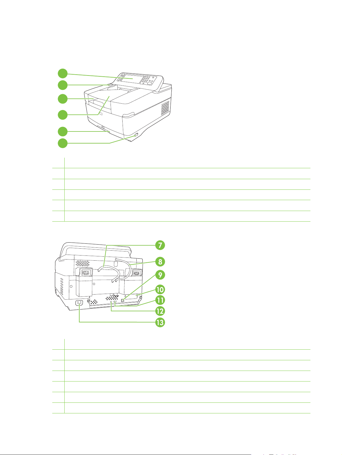
Device parts
Before using the digital sender, familiarize yourself with its parts.
1
2
3
4
5
6
1 Control panel
2 Jam release button
3 Output bin
4 ADF input bin
5 Keyboard (pull to open)
6 On/off switch
7 ADF cable
8 Control-panel cable
9 10/100Base-T network port
10 EIO slot
11 USB host port (for third-party devices only)
12 USB device port (for firmware upgrades only)
13 Power connector
6 Chapter 1 Device information ENWW
Page 23

14
14 Scanner lock
15 Serial number
16 Scanner glass
15
16
ENWW Device parts 7
Page 24
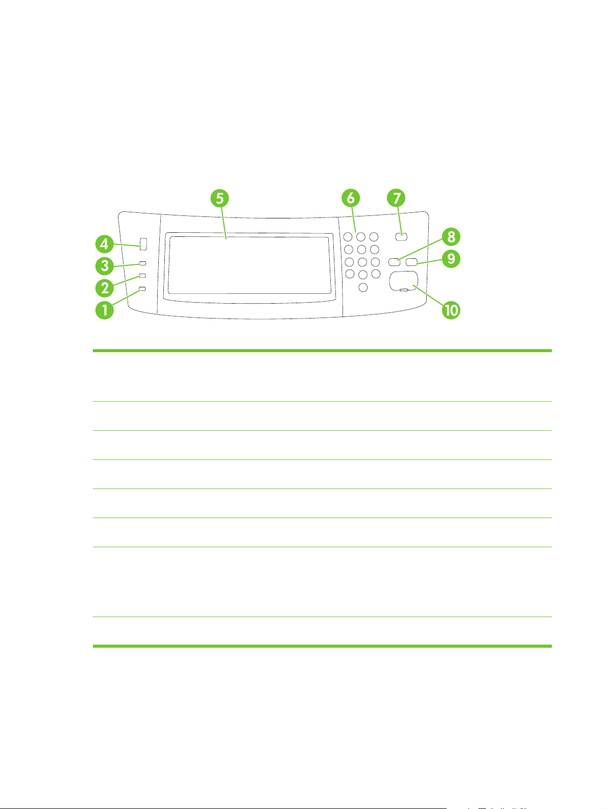
Use the control panel
The control panel has a VGA touchscreen that provides access to all device functions. Use the buttons
and numeric keypad to control jobs and the device status. The LEDs indicate overall device status.
Control-panel layout
The control panel includes a touchscreen graphical display, job-control buttons, a numeric keypad, and
three light-emitting diode (LED) status lights.
Figure 1-1 Control-panel layout
1 Attention light The Attention light indicates that the
2 Data light The Data light indicates that the device is
3 Ready light The Ready light indicates that the device
4 Brightness-adjustment dial Turn the dial to control the brightness of
5 Touchscreen graphical display Use the touchscreen to open and set up
6 Numeric keypad Use the keypad to type numeric values,
7 Sleep button and light If the device is inactive for a long period
8 Reset button Resets the job settings to factory or user-
device has a condition that requires
intervention, such as an error message
on the touchscreen.
receiving data.
is ready to begin processing a job.
the touchscreen.
all device functions.
such as a fax number.
of time, it automatically enters Sleep
mode. To place the device into Sleep
mode or to reactivate the device, press
the Sleep button. When the light is
glowing, the device is in Sleep mode.
defined default values.
8 Chapter 1 Device information ENWW
Page 25

9 Stop button Stops the active job. While stopped, the
control panel shows the options for the
stopped job (for example, if you press
Stop while the device is processing an e-
mail job, the control panel message
prompts you to cancel or resume the
job).
10 Start button and light Starts digital sending, or resumes a job
that has been interrupted. When the light
is glowing, the device is ready to start
scanning.
ENWW Use the control panel 9
Page 26

Device software
Digital-sender software
To take advantage of advanced digital-sender features such as scanning with OCR or sending to a
workflow, you can install the HP Digital Sending Software Version 4.0 (HP DSS) that is provided on a
CD-ROM with the device. This software runs as a service on a network server. It is not necessary to
install any software or drivers on individual user's computers.
See the HP Digital Sending Software Support Guide on the documentation CD for software installation
and configuration instructions.
The most recent software updates are available on the Internet at
www.hp.com/support/dss.
10 Chapter 1 Device information ENWW
Page 27

Paper handling
The HP Digital Sender 9250c supports the following standard media sizes:
Letter: 215.9 x 279 mm (8.5 x 11 inches)
●
Executive: 190 x 254 mm (7.5 x 10 inches)
●
A4: 210 x 297 mm (8.3 x 11.7 inches)
●
A5: 148 x 210 mm (5.83 x 8.27 inches)
●
B5: 176 x 250 mm (6.9 x 9.8 inches)
●
Legal (from the ADF only): 215.9 x 355.6 mm (8.5 x 14 inches)
●
Paper weight: 60 to 120 g/m2 (16 to 32 lb)
Up to 50 sheets of paper can be stacked in the ADF, up to a maximum height of 5 mm (0.2 inch).
ENWW Paper handling 11
Page 28

12 Chapter 1 Device information ENWW
Page 29

2 Installation and configuration
Chapter contents
Prepare the site
●
System requirements
●
Unpack the device
●
ENWW Chapter contents 13
Page 30
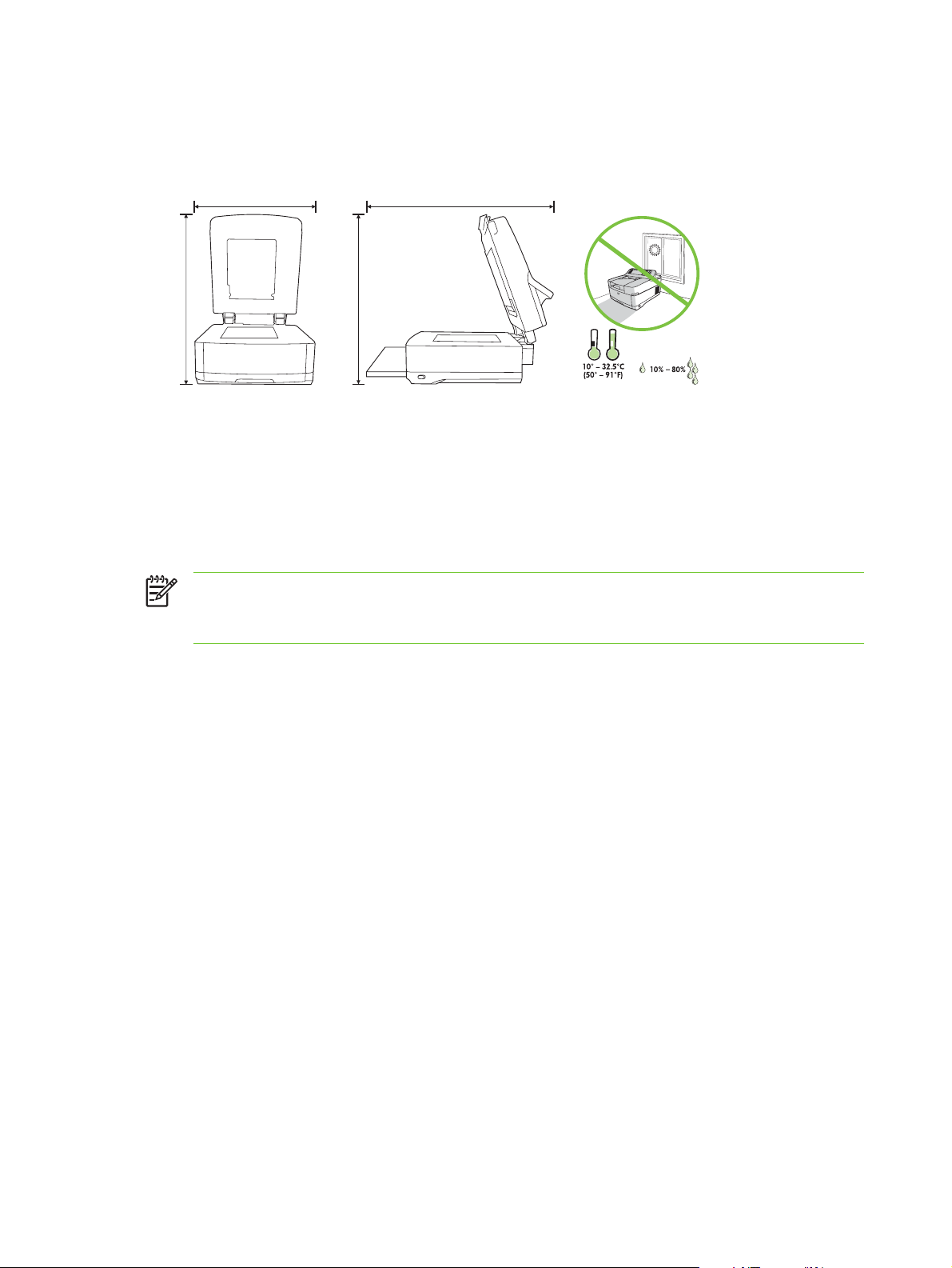
Prepare the site
720.85 mm
(28.38 inches)
720.85 mm
(28.38 inches)
452.62 mm
(17.82 inches)
724.20 mm
(28.51 inches)
Select a well-ventilated, dust-free area to install the device. Place the device on a sturdy surface.
452.62 mm
(17.82 inches)
720.85 mm
(28.38 inches)
720.85 mm
(28.38 inches)
System requirements
To install the HP Digital Sender 9250c, the computer system must have the following features:
Fast Ethernet 100Base-TX or Ethernet 10Base-T
●
Access to an SMTP e-mail gateway
●
NOTE: HP highly recommends establishing SMTP gateway on your own local area network.
However, the device can be configured for e-mail functionality even if mail services are provided
by an outside Internet service provider (ISP) over a digital subscription line (DSL).
724.20 mm
(28.51 inches)
14 Chapter 2 Installation and configuration ENWW
Page 31

Unpack the device
Remove all shipping bags, tape, and packing material.
1
2
3
4
5
1 Getting started guide (use the getting started guide for installation)
2 Digital sender documentation and HP DSS optional software
3 Digital sender
4 Control-panel overlays (if included)
5 Power cord
6 Calibration sheet
6
ENWW Unpack the device 15
Page 32

16 Chapter 2 Installation and configuration ENWW
Page 33

3 Maintenance
Chapter contents
Replace supplies and parts
●
Clean the device
●
ENWW Chapter contents 17
Page 34

Replace supplies and parts
Replace the mylar sheet
If you start to see vertical streaks on the scanned images, you might need to replace the mylar sheet at
the base of the ADF. The device ships with an envelope containing three extra mylar sheets and
installation instructions. The envelope is in a pocket behind the ADF vinyl backing, as shown in the
following figure.
C
B
A
a
A
a
A
a
A
a
A
a
c
b
b
B
C
c
C
B
c
b
C
B
c
b
C
B
c
b
Follow the instructions that come in the envelope to replace the mylar sheet.
NOTE: If necessary, you can order extra mylar sheet replacement kits from your HP sales
representative. The HP product number is Q6496A.
18 Chapter 3 Maintenance ENWW
Page 35

Replace the ADF Maintenance Kit
The device notifies you when it is time to replace the ADF Maintenance Kit by showing a message on
the control-panel display. You can view the remaining life of the Maintenance Kit at any time by pressing
the Supplies Status button on the control panel or visiting the EWS Supplies Status page (see the
embedded Web server guide on the device CD).
The ADF Maintenance Kit includes the following items:
One pickup roller assembly
●
One separation pad
●
One mylar sheet kit
●
An instruction booklet
●
Follow the instructions that come with the kit to install it.
After replacing the kit, reset the New Document Feeder Kit setting.
1. On the Home screen, touch Administration.
2. Scroll down and touch Resets.
3. Touch Reset Supplies.
4. Touch New Document Feeder Kit.
5. Touch Yes, and then touch Save.
ENWW Replace supplies and parts 19
Page 36

Clean the device
During the scanning process, paper and dust particles can accumulate inside the device. Over time,
this buildup can cause problems, such as specks on scanned documents.
Clean the exterior
Use a soft, damp, lint-free cloth to wipe dust, smudges, and stains off of the exterior of the device.
Clean the glass
Clean the glass only if dirt is visible, or if you see poor scan quality (such as streaking).
●
Clean the glass surface by wiping it gently with a clean, damp, lint-free cloth. Use an ammonia-
●
based surface cleaner to dampen the cloth.
CAUTION: Do not pour or spray liquids directly onto the glass. Do not press hard on the glass
surface, as this could break the glass.
Clean the touchscreen
Clean the touchscreen when needed to clear away fingerprints or dust build-up. To clean it, wipe the
touchscreen gently with a clean, water-dampened, lint-free cloth.
CAUTION: Use water only. Solvents or cleaners can damage the touchscreen. Do not pour or
spray water directly onto the touchscreen.
Clean the ADF delivery system
1. Open the scanner lid.
2. Locate the white, vinyl ADF backing.
20 Chapter 3 Maintenance ENWW
Page 37

3. Locate the white, vinyl calibration strips.
4. Clean the ADF backing and the calibration strips by wiping them with a clean, damp, lint-free cloth.
Use an ammonia-based surface cleaner to dampen the cloth.
5. Close the scanner lid.
ENWW Clean the device 21
Page 38

Clean the ADF rollers
You should clean the rollers in the ADF if you are experiencing misfeeds or if your originals show marks
as they exit the ADF.
CAUTION: Cleaning the rollers too frequently could introduce dust into the device.
1. Open the scanner lid.
2. Locate the rollers near the vinyl calibration strips.
3. Wipe the rollers gently with a clean, water-dampened, lint-free cloth.
CAUTION: Do not pour water directly onto the rollers. Doing so might damage the device.
4. Close the scanner lid.
5. Push the release button to open the ADF cover.
22 Chapter 3 Maintenance ENWW
Page 39

6. Locate the rollers.
7. Wipe the rollers with a clean, water-dampened, lint-free cloth.
CAUTION: Do not pour water directly onto the rollers. Doing so might damage the device.
8. Locate the separation pad.
9. Wipe the pad with a clean, water-dampened, lint-free cloth.
10. Close the ADF cover.
ENWW Clean the device 23
Page 40

24 Chapter 3 Maintenance ENWW
Page 41

4 Theory of operation
Chapter contents
Basic operation
●
Formatter system
●
Engine control system
●
Flatbed unit and ADF system
●
ENWW Chapter contents 25
Page 42

Basic operation
All high-level digital sender processes are routed through the formatter, which processes images and
communicates with other devices.
The basic digital sender operation can be divided into three systems:
The engine control system, which includes the power supply and the scanner controller board
●
The pickup-and-feed system, which consists of various rollers and transports the media through
●
the ADF
The scanner system, which scans documents and sends them to the formatter in the form of data
●
Sequence of operation (scanner)
Period (sequence) Description
Power on The period of time from when the digital sender power is turned on until the main motor begins
to rotate.
Initialization The period of time after the initial power-on sequence and before the digital sender is ready
to scan. During this time, the scanner and ADF initialization is completed, scanner calibration
is performed, and the ADF checks for media in the input tray.
Standby The period of time from the end of the initialization sequence until a request for a scan. During
this time, the scan carriage is in the Home position and the digital sender might go into Sleep
mode.
Scan The period of time immediately following a request for a scan. The scanner fan turns on, the
scan start position is adjusted, the digital sender performs the scan, and data is sent to the
formatter.
26 Chapter 4 Theory of operation ENWW
Page 43

Formatter system
The formatter is responsible for the following procedures:
Controlling Sleep mode
●
Receiving and processing scan data
●
Monitoring control-panel functions and relaying digital-sender status information (through the
●
control panel and the network)
Developing and coordinating data placement and timing with the scanner controller board
●
Communicating over the network
●
The formatter provides the electrical interface and mounting locations for one EIO card, one memory
DIMM, and the hard-disk drive. The formatter also provides two internal USB host ports (for third-party
devices), one external USB host port, and one external USB device port.
Sleep mode
This feature conserves power after the digital sender has been idle for an adjustable period of time.
When the digital sender is in Sleep mode, the control-panel backlight is turned off, but the digital sender
retains all settings. The default setting is for Sleep mode to be enabled, and the digital sender enters
the Sleep mode after a 30-minute idle time. Sleep mode can also be turned off from the
Administration menu.
CPU
The digital sender exits Sleep mode and enters the warm-up cycle when any of the following occurs:
A PML or PJL command is received
●
You touch the control-panel touchscreen or press a key on the keyboard or a button on the control
●
panel
The top cover is opened
●
Media is placed in the input tray
●
NOTE: Digital-sender error messages override the Sleep message. The digital sender enters
Sleep mode at the appropriate time, but the error message continues to appear.
The formatter incorporates a 480 MHz RISC processor.
ENWW Formatter system 27
Page 44

Memory
The formatter system contains the digital sender memory, which is divided into several components.
This section describes each memory component.
NOTE: If the digital sender encounters a problem when managing available memory, a
clearable warning message appears on the control panel.
Hard-disk drive. The digital sender comes standard with a hard disk that has a capacity of 40 GB
●
or greater. The hard disk is used to store settings.
Random-access memory on the formatter. The random-access memory (RAM) contains the
●
scanned image. Memory capacity can be increased by adding a dual inline memory module (DIMM)
to the formatter or replacing an existing DIMM with a larger DIMM. In most cases, additional
memory might be required to use the digital sender with certain other devices, such as third-party
devices. Typically, adding memory will not increase the performance of the device.
Nonvolatile memory. The digital sender uses nonvolatile memory (NVRAM) to store I/O
●
information and other permanent information, such as page counts and serial number. The
contents of NVRAM are retained when the digital sender is turned off or disconnected.
Control panel
The control panel contains both touchscreen and hard keys, and sends user commands to the formatter.
Keyboard
The keyboard tray contains a keyboard for entering e-mail addresses and other data.
Scanner controller board
The scanner controller board sends data to the formatter and receives commands from the formatter.
The scanner controller board controls motors, fans, and sensors.
Engine control system
Engine power supply circuit
The power supply consists of a low-voltage circuit. The low-voltage circuit provides uninterrupted 5 volt
(V) and 3.3 V power to the formatter, and provides 24 V, 5 V, and 3.3 V power to the scanner controller
board.
28 Chapter 4 Theory of operation ENWW
Page 45

Flatbed unit and ADF system
Electrical system
The scanner-assembly electrical system consists of the following components:
The charged-coupled device (CCD) PCA (optical assembly)
●
The inverter
●
The scanner controller board
●
The ADF intermediate board
●
Figure 4-1 Scanner assembly electrical structure on page 29 shows the scanner-assembly electrical
structure.
Scanner/controller
board
Fan drive circuit
Motor drive circuit
Motor drive circuit
Motor drive circuit
Solenoid drive circuit
Fan drive circuit
Inverter
PCA
Carriage home sensor
ADF open sensor
Flatbed fan
Carriage motor
Feed motor
Read motor
Solenoid
ADF intermediate
PCA
Carriage (Optical scan unit)
CCD
Scanning
Lamp
Image
scanner
ADF
ADF fan
Cover open sensor
Empty sensor
Registration sensor
Read sensor
Exit sensor
Bin full sensor
Paper detect
Formatter
SENPWR
Figure 4-1 Scanner assembly electrical structure
ENWW Flatbed unit and ADF system 29
+24V
Page 46

Motors and fans
The scanner assembly has three motors and three fans. The motors are stepping motors, which drive
the components inside the scanner assembly. The fans cool various motors and components in the
system.
Name Purpose Type Rotation Failure detection
Scanner motor (flatbed
motor)
Feed motor Drives the pickup, the
Read motor Drives the feed and
Scanner base fan Cools the power supply Fan Exhaust No
Scanner motor fan Cools the scanner lamp
ADF fan Cools the feed motor
Optical assembly
The optical assembly contains the lamp, five mirrors, a lens, and the charged coupled device (CCD).
Inverter
circuit
Drives the scanner
carriage unit
separation, and
registration rollers
delivery rollers
and the CCD
and the read motor
Scanning lamp
Stepping motor Varies No
Stepping motor Varies No
Stepping motor Varies No
Fan Intake Yes
Fan Exhaust Yes
Document
reflector Fourth mirror
Third mirror
Glass
Fifth mirror
Lens
CCD
CPU
Scanner
First mirror
Second mirror
Controller
Figure 4-2 Scan carriage components
The scanner lamp illuminates a small strip of the document that is called the raster line. The mirrors
direct the light through the lens to the CCD. The CCD senses and records the light, creating an analog
representation of the raster line. If the ADF is being used, the document then advances in the ADF to
the next raster line. If the flatbed is being used, the carriage advances to the next raster line. This
advancing and collection process continues to the end of the sheet.
30 Chapter 4 Theory of operation ENWW
Page 47

Optical unit home position
detection sensor
Sensor flag
MOTOR CONTROL
signals
CPU
Optical unit
motor drive circuit
MOTOR DRIVE
signals
Motor rotates in
the reverse direction
Unit moves backward carriage
Optical unit
Motor rotates in
the normal direction
Unit moves forward
glass
Motor
Optical unit motor
Figure 4-3 Optical assembly
The image data is collected on the scanner controller board, where it is processed and sent to the
formatter.
ENWW Flatbed unit and ADF system 31
Page 48

ADF feed system
The ADF has built-in duplexing capability for scanning two-sided documents. Pages from the original
document enter the ADF from the ADF input tray. A separation roller and separation pad work together
to separate the top sheet from the stack. The page passes through a set of registration rollers and two
sets of feed rollers that advance the page. A set of delivery rollers delivers the page to the ADF output
bin. A bin-full sensor detects when the ADF output bin is full and stops the feed mechanism until the bin
is emptied.
Read Motor
Registration sensor
Registration roller
Feed roller
Read sensor
Scanning position
Figure 4-4 ADF paper path and sensors
Separation roller
Empty sensor
Separation pad
Exit sensor
Optical unit
Cover open sensor
Pickup roller
Delivery roller
ADF input tray
Delivery tray
Bin full sensor
Feed Motor
glass
Carriage
Motor
32 Chapter 4 Theory of operation ENWW
Page 49

Jam detection
When the sensors inside the ADF detect a jam, the feed and read motors immediately stop. A signal is
sent to the scanner controller board, which notifies the formatter. An error message appears on the
control-panel display.
To clear a jam, open the jam-access cover and remove the media. When sensors do not detect media
after entering the jam state, the jam message is cleared from the control-panel display.
Residual-media jam
During the initialization sequence or after the ADF jam cover has been opened and closed, if the
registration sensor, read sensor, or exit sensor detects the presence of media, the scanner controller
board determines that a residual-media jam has occurred.
ADF pickup jam
If the leading edge of the media did not reach the registration sensor within a specific period of time, the
scanner controller board determines that an ADF pickup jam has occurred.
ADF jam
ADF jams can occur in three places inside the ADF.
Registration-sensor jam
If the registration sensor does not detect the trailing edge of the media after the leading edge reaches
the scan-ready position, the scanner-controller board determines that an ADF jam has occurred.
Also, when the scanner duplexer is in use, if the registration sensor does not detect the leading edge
of the media after a specific period of time after media enters the duplexer, the scanner-controller board
determines that an ADF jam has occurred.
Read-sensor jam
If the read sensor does not detect the leading edge of the media within a specific period of time, or if
the read sensor does not detect the trailing edge of the media within a specific period of time after it
detects the leading edge, the scanner-controller board determines that an ADF jam has occurred.
Exit-sensor jam
If the exit sensor does not detect the leading edge of the media within a specific period of time after the
leading edge reaches the read sensor, or if the exit sensor does not detect the trailing edge of the media
within a specific period of time after the read sensor detects the trailing edge, the scanner-controller
board determines that an ADF jam has occurred.
ADF cover-open jam
If the ADF jam-access cover is opened while media is feeding through the ADF, a jam occurs.
ADF open jam
If the ADF is opened while media is feeding through the ADF, a jam occurs.
ENWW Flatbed unit and ADF system 33
Page 50

34 Chapter 4 Theory of operation ENWW
Page 51

5 Removal and replacement
This chapter contains information about the following topics:
Removal and replacement strategy
●
User-replaceable parts
●
External components and covers
●
Internal components
●
ENWW 35
Page 52

Removal and replacement strategy
This chapter describes how to remove, replace, and reassemble the major assemblies of the digital
sender. Replacement is generally the reverse of removal.
WARNING! Unplug the power cord from the power outlet (at the wall receptacle) before
attempting to service the digital sender. If you do not follow this warning, severe injury can result.
Certain functional checks during troubleshooting might require power to be supplied to the digital
sender. However, all power should be turned off and the product should be unplugged when you
remove any digital sender assemblies or components. Never operate or service the digital sender
when the protective cover is removed from the laser/scanner assembly. The reflected beams,
although invisible, can damage your eyes.
CAUTION: The product contains components that are sensitive to electrostatic discharge
(ESD). Always perform service work at an ESD-protected workstation. If an ESD-protected
workstation is not available, discharge body static by grasping the digital sender chassis before
touching an ESD-sensitive component. Ground the digital sender chassis before servicing the
digital sender.
NOTE: To identify the left side and right side of the digital sender, face the control panel.
Required tools
#1 Phillips screwdriver
●
#2 Phillips screwdriver
●
#2 Phillips screwdriver with a shaft diameter of 6 mm (0.25 inch) or less
●
Short #2 Phillips screwdriver shaft length of 76 mm (3.0 inches)
●
Right-angle #2 Phillips screwdriver
●
Small flat-blade screwdriver
●
Needle-nose pliers
●
ESD mat (if available; see the preceding ESD caution)
●
Penlight (optional)
●
Tape (optional)
●
CAUTION: A pozidriv screwdriver can damage screw heads on the product. Use a #2 Phillips
screwdriver.
Before performing service
If possible, go to the digital sender embedded Web server and print the configuration page.
●
36 Chapter 5 Removal and replacement ENWW
Page 53

After completing service
Reconnect all cables to the product.
●
Replace all of the accessories.
●
Verify that the most recent firmware is installed. See
●
Screws that are used in the digital sender
This table describes the screws that are used in the digital sender and provides guidelines to help
determine where each type of screw is used. The screws can vary in length depending on the thickness
of the material that is being fastened. Always note where each type of screw is located and replace each
one in its original location.
NOTE: When you are disassembling the product, place the screws into the chassis holes from
which they were removed. This prevents their loss, and ensures that the proper type and length
of screw for each location is used when the product is reassembled
Table 5-1 Common fasteners that are used in this digital sender
Drawing and description Purpose
This screw is used to fasten metal to metal when good electrical contact is needed.
This screw also provides high resistance to loosening.
Phillips-head machine screw with captive
star washer
This screw is used to fasten sheet metal or plastic to plastic frames. The deep,
coarsely spaced threads provide an increased holding capability while decreasing
the possibility of stripping the target hole.
Upgrade the firmware on page 148.
Phillips-head screw with self-tapping
threads
Phillips washer-head machine screw with
a broad, flat washer attached to the screw
head
Screw measurement guide
NOTE: To install a self-tapping screw, first turn it counterclockwise to
align it with the existing thread pattern, and then carefully turn it clockwise
to tighten it. You will feel resistance and hear the screw click when it
engages the existing threads in the hole. Do not overtighten the screw. If
a self-tapping screw-hole becomes stripped, repair the screw-hole or
replace the affected assembly.
This screw is used to fasten sheet metal parts to the sheet metal chassis. It spans
large clearance holes and distributes the load by increasing the bearing surface.
ENWW Removal and replacement strategy 37
Page 54

User-replaceable parts
Separation pad
●
Pickup-roller cover
●
Pickup roller assembly
●
Mylar-holder assembly
●
ADF mylar shield
●
Control panel
●
Control-panel overlays
●
Formatter assemblies
●
Hinge flaps
●
Paper input tray
●
38 Chapter 5 Removal and replacement ENWW
Page 55

Separation pad
1. Open the ADF top cover.
Figure 5-1 Removing the separation pad (1 of 3)
2. Raise the separation pad frame assembly.
2
1
Figure 5-2 Removing the separation pad (2 of 3)
ENWW User-replaceable parts 39
Page 56

3. Push the bottom edge of the separation pad away from the frame.
Figure 5-3 Removing the separation pad (3 of 3)
4. Remove the separation pad.
40 Chapter 5 Removal and replacement ENWW
Page 57

Pickup-roller cover
1. Open the ADF top cover.
1
Figure 5-4 Removing the paper input tray (1 of 2)
2. Open the pickup-roller cover by pressing the locking tab and rotating the top of the assembly away
from the ADF.
2
Figure 5-5 Removing the pickup roller assembly (2 of 3)
ENWW User-replaceable parts 41
Page 58

3. Release two clips (callout 1) to remove the cover.
1
Figure 5-6 Removing the pickup-roller cover (2 of 2)
42 Chapter 5 Removal and replacement ENWW
Page 59

Pickup roller assembly
1. Open the ADF top cover.
1
Figure 5-7 Removing the pickup roller assembly (1 of 3)
2. Open the pickup-roller cover by pressing the locking tab and rotating the top of the assembly away
from the ADF.
2
Figure 5-8 Removing the pickup roller assembly (2 of 3)
3. Pull the left side (gear end) of the roller-assembly drive shaft to disengage it, and then slide the
assembly toward the left of the device to remove it.
1
2
Figure 5-9 Removing the pickup roller assembly (3 of 3)
ENWW User-replaceable parts 43
Page 60

Mylar-holder assembly
1. Open the ADF/scanner assembly and release the locking tabs on the mylar-holder assembly.
Figure 5-10 Removing the mylar-holder assembly (1 of 3)
The mylar-holder assembly should drop open.
Figure 5-11 Removing the mylar-holder assembly (2 of 3)
44 Chapter 5 Removal and replacement ENWW
Page 61

2. Remove the mylar-holder assembly by unclipping two clips (callout 1) and pulling the assembly
toward you.
1
Figure 5-12 Removing the mylar-holder assembly (3 of 3)
ENWW User-replaceable parts 45
Page 62

ADF mylar shield
1. Remove the mylar-holder assembly. See Mylar-holder assembly on page 44.
2. Carefully unhook the mylar shield from the four tabs on the mylar-holder assembly, and then
remove and discard the mylar shield.
Figure 5-13 Replacing the ADF mylar shield (4 of 7)
3. Use a dry cloth to clean the white strips inside of the mylar-holder assembly.
4. Insert a new mylar shield, and clip it onto the four tabs on the mylar-holder assembly.
NOTE: Make sure that you do not leave fingerprints on the new mylar shield.
Figure 5-14 Replacing the ADF mylar shield (5 of 7)
46 Chapter 5 Removal and replacement ENWW
Page 63

Control panel
1. Turn the two latches (callout 1) counterclockwise 90° until they click.
Figure 5-15 Removing the control panel (1 of 2)
1
2. Rotate the top of the control panel away from the device and disconnect one connector to free the
control panel from the device.
Figure 5-16 Removing the control panel (2 of 2)
3. Remove the control panel.
ENWW User-replaceable parts 47
Page 64

Control-panel overlays
Use a small flatblade screwdriver to release the two control-panel overlays.
Figure 5-17 Removing the control-panel overlays
48 Chapter 5 Removal and replacement ENWW
Page 65

Formatter assemblies
Formatter cage
Unscrew the thumb screws at the back of the device and use them to pull the formatter cage out of the
unit.
Figure 5-18 Removing the formatter cage
ENWW User-replaceable parts 49
Page 66

Hard-disk drive
WARNING! The product contains components that are sensitive to electrostatic discharge
(ESD). Always perform service work at an ESD-protected workstation. If an ESD-protected
workstation is not available, discharge body static by grasping the device chassis before touching
an ESD-sensitive component. Ground the device chassis before servicing the product.
1. Remove the formatter cage (see Formatter cage on page 49), open the formatter-cage door, and
then disconnect the hard-disk drive cables (callout 1) from the hard-disk drive.
1
Figure 5-19 Removing the hard drive (1 of 2)
2. Slide the hard-disk drive to the right to remove it.
Figure 5-20 Removing the hard drive (2 of 2)
50 Chapter 5 Removal and replacement ENWW
Page 67

Hard-disk drive cables
WARNING! The product contains components that are sensitive to electrostatic discharge
(ESD). Always perform service work at an ESD-protected workstation. If an ESD-protected
workstation is not available, discharge body static by grasping the device chassis before touching
an ESD-sensitive component. Ground the device chassis before servicing the product.
1. Remove the formatter cage (see Formatter cage on page 49), open the formatter-cage door, and
then disconnect the hard-disk drive cables from the hard-disk drive (callout 1).
1
Figure 5-21 Removing the hard-disk drive cables (1 of 2)
2. Disconnect the hard-disk-drive cables from the formatter (callout 2).
2
Figure 5-22 Removing the hard-disk drive cables (2 of 2)
ENWW User-replaceable parts 51
Page 68

Memory DIMM
1. Push down on the two tabs (callout 1) to release the memory DIMM.
Figure 5-23 Removing the memory DIMM
1
2. Lift the DIMM out of the formatter.
52 Chapter 5 Removal and replacement ENWW
Page 69

Hinge flaps
Slide a small flat blade screwdriver between the hinge flaps (callout 1) and their housing and then gently
pry the flaps away from the device.
Figure 5-24 Removing the hinge flaps
ENWW User-replaceable parts 53
Page 70

Paper input tray
1. Open the ADF top cover.
Figure 5-25 Removing the pickup-roller cover (1 of 2)
2. Pull the hinge out of its hole on the left side of the paper input tray, and then slide the tray toward
the left side of the device to remove the tray.
2
1
Figure 5-26 Removing the paper input tray (2 of 2)
54 Chapter 5 Removal and replacement ENWW
Page 71

External components and covers
Keyboard
●
Control-panel lower cover
●
Control-panel upper cover
●
Control-panel cover assembly
●
External control-panel cable
●
Output bin base cover or output bin extender
●
Output bin paper lever
●
ADF right cover
●
ADF right-corner cover
●
ADF left cover
●
ADF left-corner cover
●
ADF rear cover
●
Scanner right cover
●
Scanner left cover
●
Scanner front cover
●
Scanner rear cover
●
Right hinge cover
●
Left hinge cover
●
Upper hinge cover
●
ENWW External components and covers 55
Page 72

Keyboard
1. Pull out the keyboard tray.
2. Use a small flat blade screwdriver to slide four tabs (callout 1) toward the keys.
1
Figure 5-27 Removing the keyboard (1 of 3)
3. Use the screwdriver to lift the keyboard slightly, and then slowly rotate the keyboard away from the
tray.
Figure 5-28 Removing the keyboard (2 of 3)
56 Chapter 5 Removal and replacement ENWW
Page 73

4. Turn the keyboard over, disconnect one cable (callout 2), and then lift the keyboard away from the
device.
2
Figure 5-29 Removing the keyboard (3 of 3)
ENWW External components and covers 57
Page 74

Control-panel lower cover
1. Remove the control panel. See Control panel on page 47.
2. Remove four screws (callout 1).
1
Figure 5-30 Removing the control-panel lower cover
3. Remove the control-panel lower cover.
58 Chapter 5 Removal and replacement ENWW
Page 75

Control-panel upper cover
1. Remove the following items:
Control panel. See
●
Control-panel lower cover. See
●
2. Remove five screws (callout 1) in the back of the control panel, and pull two plastic tabs (callout 2)
toward you to release the control-panel upper cover.
Control panel on page 47.
Control-panel lower cover on page 58.
1
2
Figure 5-31 Removing the control-panel upper cover
3. Remove the control-panel upper cover.
ENWW External components and covers 59
Page 76

Control-panel cover assembly
1. Remove the control panel. See Control panel on page 47.
2. Remove three screws (callout 1).
1
Figure 5-32 Removing the control-panel cover assembly (1 of 6)
3. Slide the rear control-panel cover past the latches and remove the cover.
4. Remove two screws (callout 2).
2
Figure 5-33 Removing the control-panel cover assembly (2 of 6)
60 Chapter 5 Removal and replacement ENWW
Page 77

5. At the back of the device, use a flat blade screwdriver to pry two tabs (callout 3) toward you at the
bottom ends of the tabs.
Figure 5-34 Removing the control-panel cover assembly (3 of 6)
6. Unhook the white plastic arm by gently pulling the tab toward you.
Figure 5-35 Removing the control-panel cover assembly (4 of 6)
7. Lift the control-panel cover assembly off of the device, rotate the front of the assembly toward the
back of the device, and then set the assembly down on the work surface.
ENWW External components and covers 61
Page 78

8. Remove one screw (callout 4).
Figure 5-36 Removing the control-panel cover assembly (5 of 6)
9. Remove the scanner rear cover by firmly pulling the cover toward you.
10. Remove one screw (callout 5) to release the metal wire clip, open two cable guides (callout 6), and
then disconnect one cable (callout 7) to release the control-panel cover assembly from the device.
5
6
7
Figure 5-37 Removing the control-panel cover assembly (6 of 6)
62 Chapter 5 Removal and replacement ENWW
Page 79

External control-panel cable
1. Perform steps 1 through 3 of removing the control panel cover assembly. See Control-panel cover
assembly on page 60.
2. Remove two screws (callout 1).
1
Figure 5-38 Removing the external control-panel cable
3. Perform steps 7 through 9 of removing the control panel cover assembly.
4. Remove the external control-panel cable.
NOTE: During reinstallation, make sure that the cable is routed correctly.
ENWW External components and covers 63
Page 80

Output bin base cover or output bin extender
1. Remove the mylar replacement kit (envelope).
2. Gently peel back the white scan background far enough to uncover four screws (callout 1).
NOTE: The foam backing should not tear if the white scan background is peeled back
gently.
3. Remove four screws (callout 1) and remove the output bin base cover or the output bin base
extender.
1
Figure 5-39 Removing the output bin base cover or output bin extender
64 Chapter 5 Removal and replacement ENWW
Page 81

Output bin paper lever
1. Remove the output bin base cover or the output bin extender. See Output bin base cover or output
bin extender on page 64.
2. Remove the output bin paper lever.
Figure 5-40 Removing the output bin paper lever
ENWW External components and covers 65
Page 82

ADF right cover
1. Open the ADF top cover.
Figure 5-41 Removing the ADF right cover (1 of 3)
2
1
2. Remove the paper input tray. See
3. Remove one screw (callout 1).
Paper input tray on page 54.
1
Figure 5-42 Removing the ADF right cover (2 of 3)
66 Chapter 5 Removal and replacement ENWW
Page 83

4. Open the ADF, remove two screws (callout 2), and release one tab (callout 3).
2
3
Figure 5-43 Removing the ADF right cover (3 of 3)
5. Lift off the ADF right cover.
NOTE: During reinstallation make sure that the rear corner of the ADF right cover is positioned
first.
ENWW External components and covers 67
Page 84

ADF right-corner cover
1. Remove the ADF right cover. See ADF right cover on page 66.
2. Release two tabs (callout 1).
1
Figure 5-44 Removing the ADF right-corner cover
3. Remove the ADF right-corner cover.
68 Chapter 5 Removal and replacement ENWW
Page 85

ADF left cover
1. Open the ADF top cover.
Figure 5-45 Removing the ADF left cover (1 of 3)
2. Remove one screw (callout 1) and release the arm (callout 2).
2
1
2
1
Figure 5-46 Removing the ADF left cover (2 of 3)
ENWW External components and covers 69
Page 86

3. Open the ADF and remove two screws (callout 3).
3
Figure 5-47 Removing the ADF left cover (3 of 3)
4. Lift off the ADF left cover.
70 Chapter 5 Removal and replacement ENWW
Page 87

ADF left-corner cover
1. Remove the ADF left cover. See ADF left cover on page 69.
2. Release two tabs (callout 1).
1
Figure 5-48 Removing the ADF left-corner cover
3. Remove the ADF left-corner cover.
ENWW External components and covers 71
Page 88

ADF rear cover
1. Remove the following covers:
Control panel cover assembly. See
●
ADF right cover. See
●
ADF left cover. See
●
2. Remove three screws (callout 1).
ADF right cover on page 66.
ADF left cover on page 69.
Control-panel cover assembly on page 60.
1
Figure 5-49 Removing the ADF rear cover
3. Remove the ADF rear cover.
72 Chapter 5 Removal and replacement ENWW
Page 89

Scanner right cover
1. Remove three screws (callout 1).
Figure 5-50 Removing the scanner right cover
1
2. Remove the scanner right cover.
ENWW External components and covers 73
Page 90

Scanner left cover
1. Remove three screws (callout 1).
Figure 5-51 Removing the scanner left cover
1
2. Remove the scanner left cover.
74 Chapter 5 Removal and replacement ENWW
Page 91

Scanner front cover
1. Remove the following covers:
Scanner right cover. See
●
Scanner left cover. See
●
2. Remove three screws (callout 1).
Scanner right cover on page 73.
Scanner left cover on page 74.
1
Figure 5-52 Removing the scanner front cover
3. Remove the scanner front cover.
ENWW External components and covers 75
Page 92

Scanner rear cover
1. Remove one screw (callout 1).
Figure 5-53 Removing the scanner rear cover
1
2. Remove the scanner rear cover by firmly pulling the cover toward you and slightly to the left. Slide
the scanner rear cover slightly left to clear the ridge on the right side.
76 Chapter 5 Removal and replacement ENWW
Page 93

Right hinge cover
1. Remove the scanner rear cover. See Scanner rear cover on page 76.
2. Remove two screws (callout 1).
1
Figure 5-54 Removing the right hinge cover
3. Remove the right hinge cover.
ENWW External components and covers 77
Page 94

Left hinge cover
1. Remove the scanner rear cover. See Scanner rear cover on page 76.
2. Remove two screws (callout 1).
1
Figure 5-55 Removing the left hinge cover
3. Remove the left hinge cover.
78 Chapter 5 Removal and replacement ENWW
Page 95

Upper hinge cover
Firmly pry off the upper hinge cover (callout 1).
Figure 5-56 Removing the upper hinge cover
1
ENWW External components and covers 79
Page 96

Internal components
ADF assembly
●
ADF jam access latch
●
Right hinge guide
●
Left hinge guide
●
Damper cover, left damper spring, right damper spring, or damper base cover
●
White mylar backing or white mylar backing spring
●
Fan filter
●
ADF cable
●
Separation pad case
●
Clear plastic paper guide
●
White scan background
●
Scanner controller board
●
Flatbed scanner assembly
●
Power supply
●
Keyboard cable
●
Power-switch assembly
●
Scanner base fan
●
Power plug
●
SCB cable
●
Internal control-panel cable
●
80 Chapter 5 Removal and replacement ENWW
Page 97

ADF assembly
1. Remove the scanner rear cover. See Scanner rear cover on page 76.
2. Remove one screw (callout 1) from the metal cable-retaining bracket, and then remove the bracket.
1
Figure 5-57 Removing the ADF assembly (1 of 3)
3. Unclip three wire clips (callout 2) and release the wires.
2
Figure 5-58 Removing the ADF assembly (2 of 3)
ENWW Internal components 81
Page 98

4. Remove one grounding screw and wire (callout 3), and disconnect three cable connectors
(callout 4).
3
4
Figure 5-59 Removing the ADF assembly (3 of 3)
5. Remove the ADF assembly by lifting it up and lifting the rear hinges out of their sockets.
NOTE: Make sure you calibrate the scanner when necessary.
82 Chapter 5 Removal and replacement ENWW
Page 99

ADF jam access latch
1. Remove the following covers:
Control panel cover assembly. See
●
ADF right cover. See
●
ADF left cover. See
●
ADF rear cover. See
●
2. Using your fingers or a flatblade screwdriver, separate two clips (callout 1) and shift the latch to
the right so that the notches are aligned.
ADF right cover on page 66.
ADF left cover on page 69.
ADF rear cover on page 72.
Control-panel cover assembly on page 60.
1
Figure 5-60 Removing the jam access latch
3. Remove the ADF jam access latch.
ENWW Internal components 83
Page 100

Right hinge guide
1. Remove the following covers:
ADF rear cover. See
●
Right hinge cover. See
●
2. Remove five screws (callout 1).
ADF rear cover on page 72.
Right hinge cover on page 77.
1
Figure 5-61 Removing the right hinge guide
3. Lift the ADF up to release the right hinge guide.
84 Chapter 5 Removal and replacement ENWW
 Loading...