

Page 1

Owning and Operating the HP 8410 Network
Analyzer
Mark Kahrs, KB2VSQ
9 Everitt Place
Maplewood, NJ 07040A
kahrs@caip.rutgers.edu
http://www.caip.rutgers.edu/kahrs
September 8, 2000
Abstract
The HP 8410 Network Analyzer offersthecheapestand most cost effective solution for network analysis (particularly scattering parameters) above
6 GHz. The paper details the various parts of the 8410 along with the various
trials and tribulations of building an automated 8410 system.
1 Introduction
Kurokawa[1] introduced the generalized scattering parameter (S-parameter) in
1965. S-parameters are extremely useful for all types of microwave circuit design including amplifiers and oscillators[2]. Therefore, when the HP 8410 was
introduced in 1967, it revolutionizedmicrowave design.
It used the new 1430A sampler together with a superheterodyne receiver architecture to produce a calibrated microwavereceiver. Together with the test sets,
it can measure transmission and reflection coefficients for any two port device.
Subsequent offerings from HP (and others) have concentrated on the lower end as
shown in the following table:
As can be seen, the only analyzers that cover above 3 GHz (without internal
doublers) are the 8410, the 8510Aand the 8720. The 8510A/B/C and 8720A are
1
Page 2
Model Freq. Range(GHz) Std. Source Test set Comments
Test Set
Oscillator
Sweep
Mixer/
Display Unit
8410
MainframeSampler
8407A 0.001-0.110 8601A none Compatible with 8410 plugins
8410ABC .11-18 8620C Many: 874x Needs display plugins
8505A 0.0005-1.3 internal 8503A 8501A normalizer
8510ABC 0.045-26 8341A 851x The gold standard of analyzers
8712ABC 0.0003-3 internal internal production use
8720ABCD 0.045-26 internal internal “Improved” version of 8510A
8753ABCD 0.003-3 internal 85046B,47A option 006 goes to 6 GHz
8754A 0.004-1.3 internal 850xx H26 option goes to 2.6 GHz
Table 1: HP network analyzers
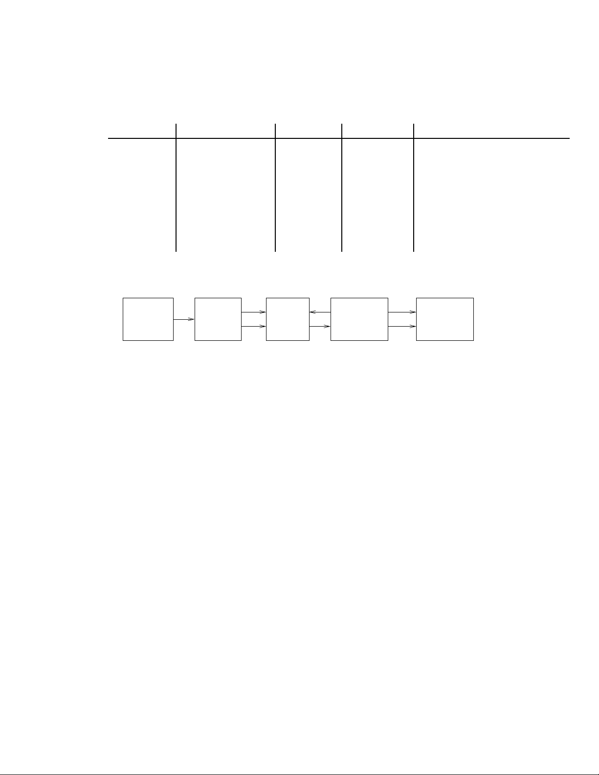
Figure 1: 8410 Block diagram
still out of the reach of all but the most well funded of amateurs. That leaves the
8410.
The paper discusses the various parts of the 8410 as well as the complications
of trying to automate it. Also included is a discussion of the woes of calibration.
2 Principles of operation
Before discussing the various parts and components of the 8410, it will be useful
to see how they fit into the whole scheme. The overall schematic is shown in
Figure 1. Here, the swept signal source introduces an RF signal into the test set.
The RF signal is divided into test and reference signals. The reference signal is
passed directly to the first mixer stage. The test signal goes through the unit under
test and then to the mixer. Most test sets permit the selection of a particular Sparameter set-up by engaging the RF relays inside the set. The 8411A harmonic
converter(shown in Figure 2) contains a sampler for each channel. The mainframe
tries to maintain phase lock between the sampler and the sweep oscillator. It also
downconverts the input to a 278 KHz IF. This is given to the display unit(s).
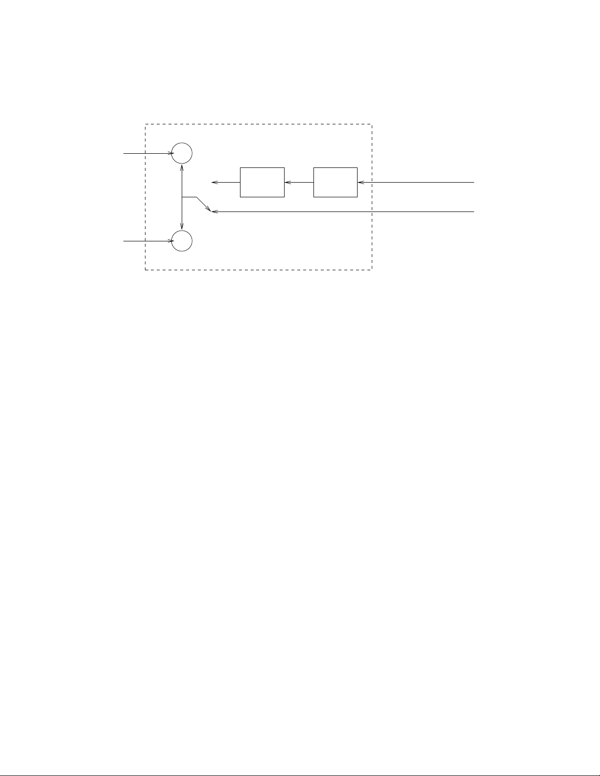
The inside of the 8411A harmonic converter is shown in Figure 2. The first
2
Page 3
X
X
SRD
external VCO
From 8410 mainframe
T
R
VCO
Figure 2: 8411A Block diagram
RF mixer (a Grove sampler[3]) is inside the 8411A harmonic converter; a Step
Recovery Diode, driven by a VCO inside the 8411A generates harmonics which
are used to down sample the input signal to 20.278 MHz. The Phase Lock Loop
(PLL) inside the 8410 mainframe tries to maintain lock by controlling the VCO.
The 20.278 Mhz signals are then downconvertedagain by heterodyning with a 20
MHz reference resulting in a 278 KHz IF. This signal is the output signal of the
mainframe to the display units.
3 The 8410 receiver
The 8410 receiver comes in 3 models:A, B and C. The major change occurred
from A to B when many changes were made to the phase lock circuits. The C
model introduces the changes made to “option H17” for the B as well as placing
the 8411A connector on the rear of the instrument. When it comes to trying to
automate the 8410, you must have a B model with the H17 option or the C model.
The H17 option introduces the wiring necessary to provide external injection of
the RF signal for the 8411; this will be explained in the automation section.
4 The 8411A harmonic converter
The 8411A is the most tempermental unit of the 8410 components. The diodes in
the sampler are delicate and sensitive to static. And of course, they are no longer
available. The plug of the 8411A is a unique HP design (shared by the 4815A).
3
Page 4

It packages several RF coax into one connector1. The 8411A comes with an
option 018, which means that the diodes in the sampler were selected for 18 GHz
operation. It must be noted that many early 8411s do not have the full complement
of pins; these units are unsuitable for automation (but not for diodes!).
5 The display units
The 8410A has a half bay for the display module. There are three choices: a
rectangular display for magnitude and phase, a meter and a polar display suitable
for Smith charts.
5.1 The 8412A rectangular display
The 8412A comes in A and B. The B revision has a connector on the rear for
connection to the 8750A storage normalizer. The test amplitude output from the
8410 mainframe is detected and then given to a log amp; this is used for dB
conversion along with the test channel phase. The same operation can be applied
to the reference channel. A multiplexor can choose between the two outputs.
5.2 The 8413A meter
Meter pin mashers will want the 8413A, however, it is seldom used but can be
used for calibration if desired.
5.3 The 8414A polar display
The 8414A also comes in a B revision with a separate vertical blanking connector
on the rear. The 8414A/B provides a
and
conversion for polar display.
6 The test sets
As discussed earlier, the test sets provide a way to measure reflection (S11 and
S22) as well as transmission (S12 and S21) parameters. The test sets are typically
controlled via a 59306A relay actuator.
1
Why didn’t HP use the standard D shell?
4
Page 5

6.1 The 8740A,41A,42A,43A reflection/transmissiontest sets
The 8740A, 8741A and 8742A are the earliest test sets. The 8740A is a reflection
test set, the 8741A and 8742A are transmission test sets. All of these units must
be considered obsolete and marginally useful because they required the user to
disconnect the Device Under Test (DUT) and reverse it.
The 8743A on the other hand is a switched reflection and transmission test
set. The external relay controls expect a 12 volt negative true signal. The 8743A
comes in a B model and also includes an option 018 for 18 GHz operation. The
11610B was a semirigid cable designed for use with the 8743A/B.
6.2 The 8745A,46A,47A,48A S-parameter test sets
The 8745A is the low frequency (0.1 to 2 GHz) S parameter test set. It can be
used with the 11600A and 11601A transistor fixtures. The 8746A is the higher
frequency set (also comes with option 018) and uses the 11608A fixture. Both of
these sets can be used with flexible arms (the 11604A and 11605A respectively).
Also included is the 11607A small signal adapter.
The 8747A series are waveguide reflection and transmission test sets. The
X8747A and P8747 are for X and P band respectively. The R8747A and K8747A
are for R and K bands respectively. They differ from the X and P band versions
since they use an external mixer and an addition CW oscillator to mix down to a
lower (2-4 GHz) band. A similar set-up for V band was described by Yamaguchi
et al. [4].
2
6.3 The 85040
The 85040A was the last test set designed for the 8410. It was part of the 8409A
analyzer system. It features more modern relays and controls and is designed to
be externally controlled by the 11713A relay controller.
7 Auxiliary units
These units are useful but not required.
2
It must be noted that the the flexible arms have been replaced by coaxial cables made by Gore
and others.
5
Page 6

7.1 The 8418A auxiliary power unit
So what do you do if you want both rectangular and polar display and you don’t
want to keep pulling one out? You need an extra power supply: the 8418A. The
8418A may also include option 70 which adds an internal 70 dB attenuator.
7.2 The 8419 interface
Imagine a day before integrated A/D converters. The 8419A/B/C is an A/D converter and 8418A power supply rolled into one. The 8419 forms an integral part
of the 8542A automated system.
7.3 The 8709A synchronizer
In order to phase lock the injected RF with the sweeper, you need an external
phase lock loop to control the external synthesizer via the FM input. The 8709A
synchronizer does this by duplicating the 8410 phase lock. The use of the 8709A
will be discussed further in section 10.2.
7.4 The 8717A bias power supply
The 8717A is a small powersupply designed expresslyfor the 8410A system (yes,
it can be used as a standalone powersupply). It is designed to be connected to the
bias connectors on the S-parameter test sets. Option 001 permits external control
of the voltages (via a D/A Converter).
7.5 The 8750A storage normalizer
The sweep rates generated by the 8410 can be very slow which leads to an annoying display. The 8750A permits storage of the 8412B display for redisplay. Note
that the 8750A can also be used for spectrum analyzers because the 8750A has
personality cards.
8 Test fixtures
For measuring coaxial components, you must use a test fixture. The 11601A
and 11602A are cute fixtures designed to mount on the 8745A . They measure
6
Page 7

transistors in the TO-18 and TO-5 packages. The fixtures also include shorts and
opens, so you can calibrate the analyzer. For more complex circuits, such as SMT
devices, the 11608A fixture is needed. It was designed to fit in the 8746A/B.
For more complex packages, the 85041A fixtures must be considered. But for
measuring “boxes” rather than components, cabling is needed.
9 Historical units
These units are of little practical use and are discussed here for completeness.
9.1 The 8327A switch
Since each test set requires an 8411A, you need multiple 8411s to cover all the
bands. Or you can switch between them. That’s what an 8327A does; these are
very rare.
9.2 The 8705A multiplexor and 8707A RF unit holder
The original RF source for the 8410A was the 8690A sweeper. Therefore, you
needed multiple BWOs for sources. The 8707A provided a way to control multiple RF units for thesweeper mainframe. The 8705A multiplexedthe outputs from
the various 8690A plugins into one RF output.
9.3 The 8710A tracking filter
Due to the harmonics present in the 5105A frequency synthesizer output3, a “filter” is needed to clean up the signal. The 8710A tracks the sweeping signal and
has its own clean VCO which is injected into the 8411A .
10 Automation
It would seem at first glance that just building an 8410 system would suffice to
have an accurate instrument. Unfortunately, this is not the case. The test sets add
additional complexity because they are part of the circuit being measured. Since
3
Recall the 5105A was before the 8660A
7
Page 8

this is no longer a lumped domain, these must be removed from the measurement. To do so requires de-embedding. So, toget the values for the de-embedding
equations, you need to digitize the output of the 8410. Originally, HP used the
8419A/B/C discrete A/D converter as discussed earlier; subsequently, they used
the 59313A A/D converter to digitize the 8414A (and also the magnitude of the
8412A due to isolation problems in the 8414A).
After de-embedding, the results need to be displayed. In the 8542A system,
they are converted back to analog via a D/A and routed via the 8414. This is not
really needed when you have a computer display at your service.
There are additional areas for automation besides digitization.
10.1 The source
The source for the 8410 system should ideally be broadband and controlled by the
same computer. The 8620C sweep oscillator is ideal, but only if you get option
011, the GPIB/HPIB option. Or, if you have more money, you can get an HP
8350A/B. Or perhaps an EIP 931.
10.2 Phase locking and harmonic skipping
As mentioned above, the 8411A uses an SRD to generate harmonics up and down
the band; it is locked via the 8410. However, the 8410A can exhibit false lock-
ing, i.e., lock onto the wrong harmonic. This, of course, leads to a measurement
error. To eliminate this problem, HP introduced external injection of the sampler
frequency controlled by an external RF synthesizer. As mentioned earlier, this
synthesizer is in turn locked via the 8709A option H17. So, this is another opportunity for computer control. With computer control, the frequency accuracy will
increase from
required to raise the level of the synthesizer to drive the SRD harmonic generator
(HP used the 8447 series of amplifiers).
MHz for the 8620C to
kHz. A power amplifier may be
11 Errors
In the ideal world, the perfect network analyzer would have infinite dynamic
range, perfect channel isolation, coupling without loss and impedance mismatches
with flat frequency response. However, we live in an inaccurate world. Random
8
Page 9

errors can of course, not be corrected (but can be averaged). Other (repeatable)
errors, such as those enumerated above, can be corrected.
These corrections can be realized by drawing the flow graph for each parameter measurement and including all the errors as well as the measurement paths.
These flow graphs can be written as equations and when combined will give a set
of equations for corrected measurements. Full details are given in HP’s application note 221[5].
12 Calibration
In order to calibrate the 8410, you need a large collection of coaxial components
including a short, a load, an open, airlines and converters from 7 mm to SMA, 7
mm to N, 7mm to 3.5 mm and so forth. A sliding load isn’t harmful either.
And, as long as you’re calibrating, you might consider a gage to check your 7
mm connectors...
13 Extensions
The sampling mixer of the 8411A has considerable loss. If you desire more dynamic range, you can replace the 8411A with external mixers (assuming you can
take the IF and put it back into the mainframe) if you use an external LO for the
mixers. This was used by a group at NASA[6] for a far field antenna range.
14 Conclusion
The 8410 is still the only networkanalyzer that is affordableand operational above
the limit set by the 8753. This paper has related some of the trials and tribulations
a system builder will encounter when buildingup such a system. As an indication,
just consider the number of cables required...
9
Page 10

References
[1] K. Kurokawa. Power waves and the scattering matrix. IEEE Trans. MTT,
pages 194–202, March 1965.
[2] R. W. Anderson. S-parameters techniques for faster, more accurate network
design. HP Journal,February 1967.
[3] W. M. Grove. Sampling for oscilloscopes and other systems: through-band.
IEEE Trans. Microwave Theory and Technique, MTT-14(12):629–635, December 1966.
[4] G. M. Yamaguchi, L. T. Yuan, and J. E. Raue. V-band network analyzer /
reflection test unit. IEEE Trans. IM, 25(4):424–431, December 1976.
[5] Hewlett-Packard. Semi-automatic measurements using the 8410b microwave
network analyzer. (221), 1977.
[6] J. D. Terry and R. R. Kunath. Using a Modified Hewlett Packard 8410 Net-
work Analyzer as an Automated Farfield Antenna Range Receiver. (NASATM-103700), 1990.
10
 Loading...