

Page 1
User’s Guide
Page 2

HP part number:
Printed in USA
March 1996
This manual applies directly to instruments with serial prefix
and
below.
This manual also applies to Ermware revision 2.0 and above. For Ermware
revisions below 2.0 contact your nearest Hewlett-Packard service center for a
Ermware upgrade.
The information contained in this document is subject to change without
notice.
Hewlett-Packard makes no warranty of any kind with regard to this material,
including but not limited to, the implied warranties of merchantability and
Etness for a particular purpose. Hewlett-Packard shall not be liable for errors
contained herein or for incidental or consequential damages in connection
with the furnishing, performance, or use of this material.
@Copyright Hewlett-Packard Company 1993, 1996
All Rights Reserved. Reproduction, adaptation, or translation without prior
written permission is prohibited, except as allowed under the copyright laws.
1400 Fountaingrove Parkway, Santa Rosa, CA 95403, USA
Page 3
The HP 8375lA/B and HP
Synthesized Sweepers
The HP 83751AA and HP
“sweepers” throughout this manual) provide continuous analog or digital
stepped sweep capability. The HP
2 to 20
to 20
high power output (approximately + 17
sweepers are SCPI and
for drop-in replacement of an HP 8350 sweep oscillator. The sweepers are
designed for optimum use with HP 8757 scalar analyzers. For specillcation
and option information, refer to Chapter 17, “Specilkations and Options,” in
this manual.
This User’s Guide is written to provide operating information to the user who
is comfortable with the front panel layout and basic operation of the sweeper.
For installation and basic sweeper operation, refer to the HP
HP
provided with your shipment.
while the HP
The “B” versions of both the HP 83751 and HP 83752 provide
programmable, with HP 8350 HP-IB mnemonics
S~thesized Sweepers Installation and Quick Start Guide,
synthesized sweepers (referred to as
provides a frequency range of
provides a frequency range of 10 MHz
maximum leveled power). The
and
111
Page 4
The Synthesized Sweeper at a Glance
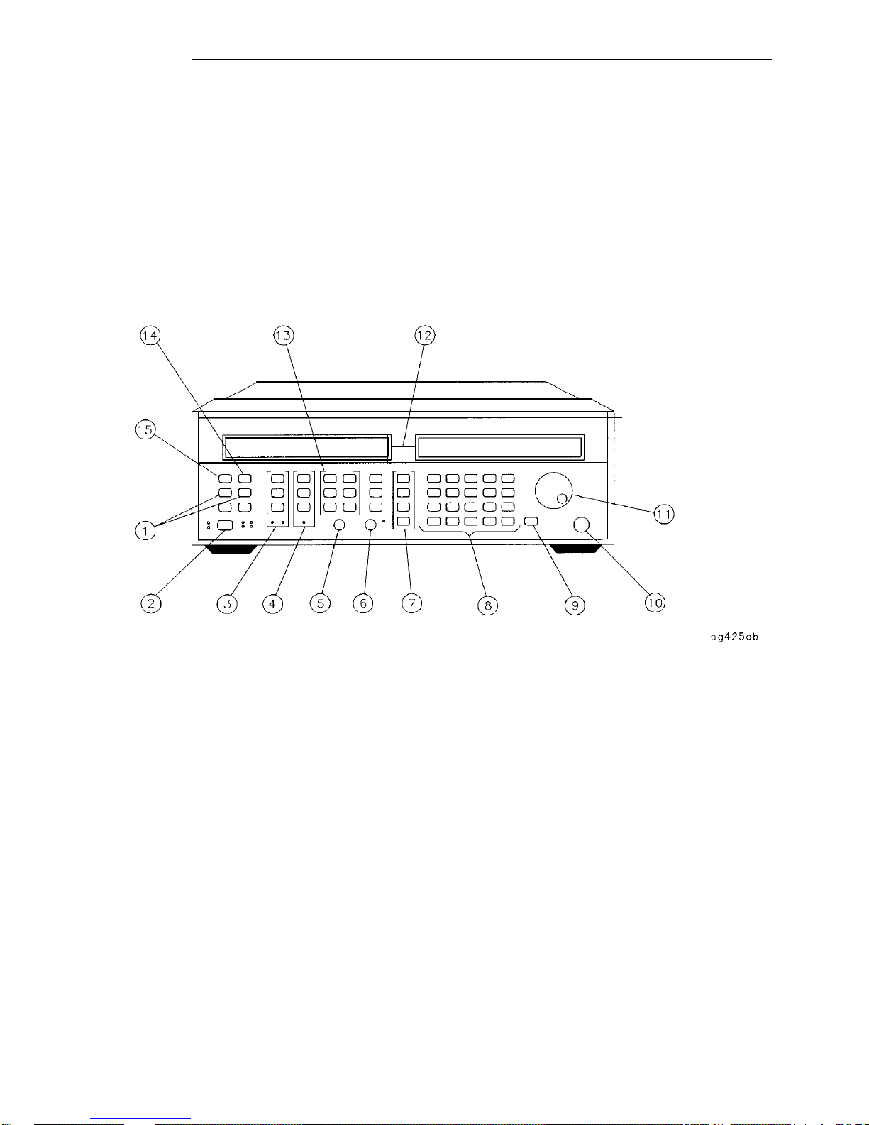
The following Egure and accompanying text explain some features of the
sweeper.
iv
The Synthesized Sweeper
Page 5
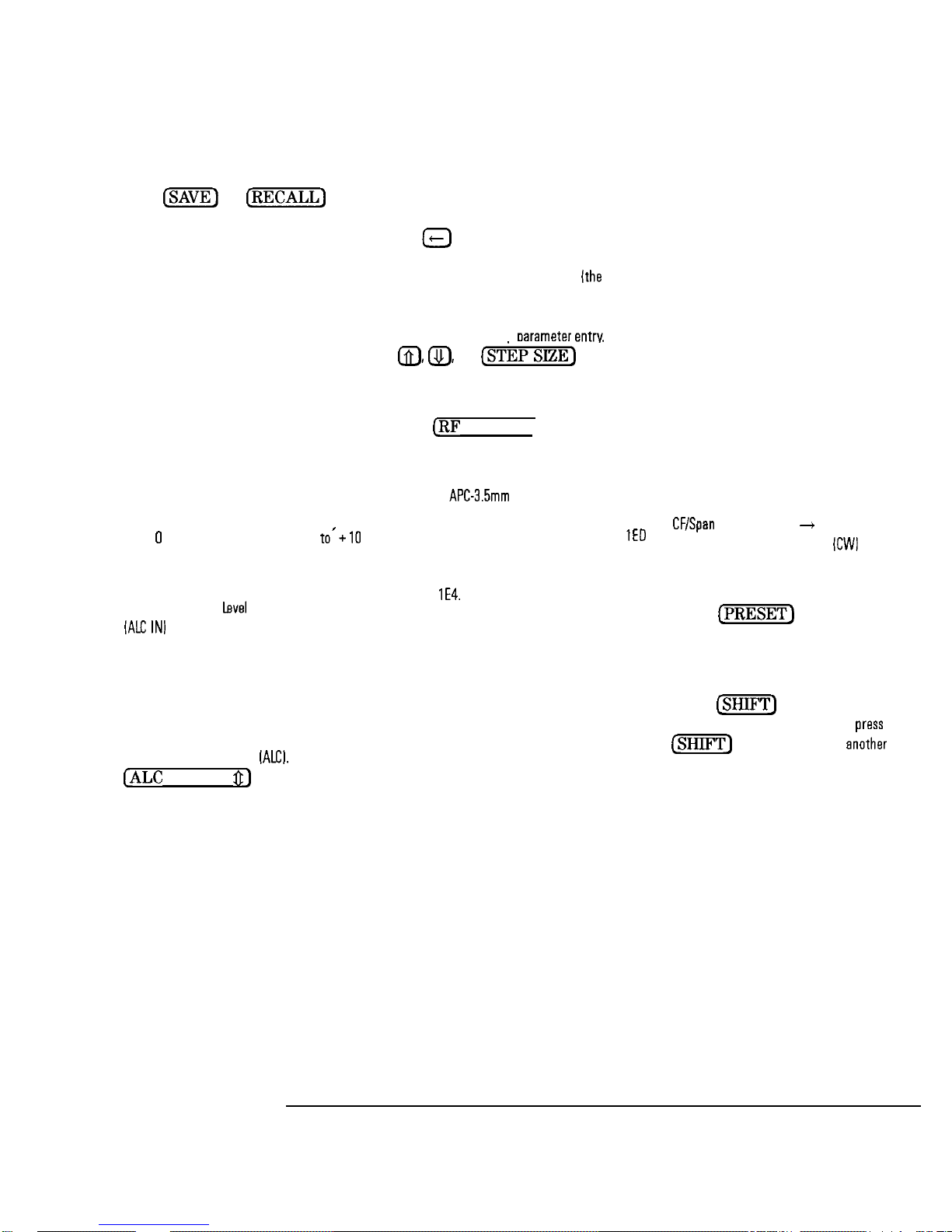
1. The
are used to save and subsequently recall
sweeper operating parameters from one of
nine nonvolatile register locations.
2. The line POWER switch turns the sweeper
to either on or standby.
3. The Marker keys allow selection of up to
ten markers to be set anywhere within the
current frequency range. Marker A
measurements are made using these keys as
well.
4. The Modulation keys allow selection of
pulse, AM, or FM modulation.
6. The SWEEP OUT BNC connector provides
voltage proportional to the sweep ranging
from
V et the start of a sweep
at the end of the sweep, regardless of sweep
width.
6. The Automatic
connector is used as the feedback
path to the sweeper when its RF output
power level is being leveled externally.
7. The Power keys allow selection of the RF
output power level of the sweeper, as well
as other power related functions, such as
Automatic Level Control
MODE
the method used to regulate the sweeper
output power level. Either internal leveling or
external leveling [with a diode, power meter,
or source module] can be selected. Additional
equipment is required when external leveling
is used.
and
Control voltage input
The
key is used to select
keys
V
6. The date entry keys are used to enter
and/or modify various sweeper parameters.
The
erroneous parameter entry before it has been
terminated. The terminator keys
rightmost column of keys) are used to choose
the units for the entered parameter as well
as to terminate the oarameter entry. The
used to increase or decrease a parameter in
predetermined steps.
9. The
toggle the RF output power on and off.
key cancels all or part of an
and
ON/OFF) key is used to
keys are
10. The RF OUTPUT connector mates with
a female
standard instruments. The connector metes
with a type-N male connector on option
instruments. The RF OUTPUT connector will
be found on the rear panel of sweepers with
option
precision connector on
11. The front panel knob is used to increase
or decrease active parameters under the
pointers, and is used in manual frequency and
power sweeps.
12. The displays show the current values of
sweeper parameters as well as the status of
many of the sweeper functions. The left-hand
display shows the current frequency status,
whether it be swept or CW. The right-hand
display shows current marker, modulation end
sweep status parameters when they are
selected, as well as the current output power
level. The annunciators that appear below
the parameters are only visible when their
associated function is active. For example, the
STEP annunciator will only be visible when
operating in stepped sweep mode.
13. The Frequency keys are used to set the
various frequency parameters for the sweeper.
Swept frequency selections include Start/Stop,
and Marker 1
functions. Continuous Wave
also be selected for- outputting single
frequencies.
14. The
the instrument into a known state. There are
two preset modes: the factory mode, and a
user-defined mode.
15. The
of some of the kevs. When vou
key and then press
the sweeper performs the function printed in
blue above the key.
Marker 2
mode may
key is used to put
key changes the function
the
key,
Sweeper rear panel features are depicted and described in detail in Chapter 7,
“Front/Rear Panel” in this manual.
V
Page 6

In This Book
This book is divided into two sections: the task reference and the dictionary
reference. These sections are subdivided into chapters. The task reference
section (identified by light blue tabs) provides step-by-step instructions for
many of the tasks that you perform with your sweeper. The chapters in the
task reference section are as follows:
Chapter 1
Chapter 2
Chapter 3
“Performing the Operator’s Check,
assuring you that your instrument is operating correctly.
“Externally Leveling the Sweeper,
steps necessary to externally level your sweeper with
detectors/couplers/splitters, power meters, and source
modules.
“Generating a Stepped Sweep,” explains how to set up the
instrument to generate a stepped sweep.
contains a procedure for
provides the
Chapter 4 “Generating a Millimeter Signal,” illustrates the setups for
using a millimeter head with your option
Chapter 5
Chapter 6
The dictionary reference section (identified by dark blue tabs) provides
information about instrument features and functions. Information is divided
into chapters as follows:
“Creating User Flatness Arrays,” explains how to create user
flatness correction arrays, which calibrate the power level at
a remote test port.
“Operating a Master/Slave Setup,
to configure two sweepers for two-tone measurement
capabilities.
shows the steps necessary
sweeper.
Chapter 7
Chapter 8
Chapter 9 “Marker Keys,
vi
“Front/Rear Panel,
aspects of the sweeper front and rear panel. (For example,
you turn to this chapter for information on the sweepers
various connectors).
“Instrument State Keys,” explains the functions of the keys
in the Instrument State group.
Markers group.
contains entries that explain different
explains the functions of the keys in the
Page 7

Chapter 10
“Modulation Keys,’ explains the functions of the keys in the
Mod group.
Chapter 11
Chapter 12
Chapter 13
Chapter 14
Chapter 15
Chapter 16
Chapter 17
Chapter 18
“Frequency Keys,” explains the functions of the keys in the
Frequency group.
“Sweep Keys,” explains the functions of the keys in the
Sweep group.
“Power Keys,
explains the functions of the keys in the
Power group.
“Entry Keys,” explains the functions of the keys in the Entry
group.
“Special Functions,
explains the various selections in the
special functions menu, which is accessed by selecting
SPECIAL.
“Error Messages,” contains lists of the error messages that
might be generated during use of the instrument.
“Specifications and Options,” contains a list of the sweeper’s
warranted performance specifications and typical operating
parameters, as well as the various mechanical, electrical,
warranty, and documentation options that are available.
“Safety and Regulatory information,
contains required
regulatory and safety information that is not included
elsewhere in the instrument documentation.
Vii
Page 8
Certification
Hewlett-Packard Company certihes that this product met its published
specifications at the time of shipment from the factory. Hewlett-Packard
further certifies that its calibration measurements are traceable to the United
States National Institute of Standards and Technology, to the extent allowed
by the Institute’s calibration facility, and to the calibration facilities of other
International Standards Organization members.
The “Safety and Regulatory Information” chapter contains regulatory
information.
Page 9

Warranty
This Hewlett-Packard instrument product is warranted against defects in
material and workmanship for a period of one year from date of shipment.
During the warranty period, Hewlett-Packard Company will, at its option,
either repair or replace products which prove to be defective.
For warranty service or repair, this product must be returned to a service
facility designated by Hewlett-Packard. Buyer shall prepay shipping charges
to Hewlett-Packard and Hewlett-Packard shall pay shipping charges to return
the product to Buyer. However, Buyer shall pay all shipping charges, duties,
and taxes for products returned to Hewlett-Packard from another country.
Hewlett-Packard warrants that its software and
Hewlett-Packard for use with an instrument will execute its programming
instructions when properly installed on that instrument. Hewlett-Packard
does not warrant that the operation of the instrument, or software, or
firmware will be uninterrupted or error-free.
LIMITATION OF WARRANTY
The foregoing warranty shall not apply to defects resulting from improper
or inadequate maintenance by Buyer, Buyer-supplied software or
interfacing, unauthorized modihcation or misuse, operation outside of the
environmental specifications for the product, or improper site preparation
or maintenance.
NO OTHER WARRANTY IS EXPRESSED OR IMPLIED. HEWLETT-PACKARD
SPECIFICALLY DISCLAIMS THE IMPLIED WARRANTIES OF
MERCHANTABILITY AND FITNESS FOR A PARTICULAR PURPOSE.
EXCLUSIVE REMEDIES
THE REMEDIES PROVIDED HEREIN ARE BUYER’S SOLE AND EXCLUSIVE
REMEDIES. HEWLETT-PACKARD SHALL NOT BE LIABLE FOR ANY
DIRECT, INDIRECT, SPECIAL, INCIDENTAL, OR CONSEQUENTIAL
DAMAGES, WHETHER BASED ON CONTRACT, TORT, OR ANY OTHER
LEGAL THEORY.
designated by
ix
Page 10

Assistance
Product maintenance agreements and other customer assistance agreements
are available
Hewlett-Packard products.
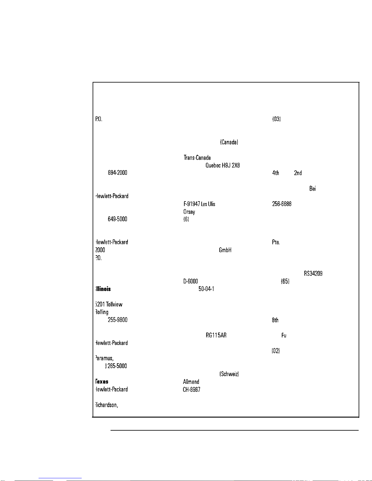
any assistance, contact your nearest
to the list of Sales and Service 0me.s
Sales and Service
on
the following page.
X
Page 11
Hewlett-Packard Sales and Service Offices
IN THE UNITED STATES
California
Hewlett-Packard Co.
1421 South Manhattan Ave
Box 4230
Fullerton, CA 92631
17141 999-6700
Hewlett-Packard Co.
301 E. Evelyn
Mountain View, CA 94039
14151
Colorado
Co.
24 Inverness Place, East
Englewood, CO 80112
3031
Georgia
Co.
Box 105005
Atlanta, GA 30339
4041 955-1500
iewlett-Packard Co.
Drive
Meadows, IL 60008
3121
Yew Jersey
Co.
120 W. Century Road
NJ 07653
201
Co.
130 E. Campbell Rd.
TX 75081
2141 231-6101
IN AUSTRALIA
Hewlett-Packard Australia Ltd.
31-41 Joseph Street
Blackburn, Victoria 3130
895-2895
IN CANADA
Hewlett-Packard
17500 South Service Road
Highway
Kirkland,
15141 697-4232
Ltd.
IN FRANCE
Hewlett-Packard France
Ulis Cedex
IN GERMAN FEDERAL
REPUBLIC
Hewlett-Packard
Vertriebszentrale Frankfurt
Berner Strasse 117
Postfach 560 140
Frankfurt 56
1061 II
IN GREAT BRITAIN
Hewlett-Packard Ltd.
King Street Lane
Winnersh, Wokingham
Berkshire
0734 784774
IN OTHER EUROPEAN
COUNTRIES
Hewlett-Packard
2
Widen [Zurich]
100411 57 31 21 11
AG
IN JAPAN
Yokogawa-Hewlett-Packard Ltd.
29-21 Takaido-Higashi, 3 Chome
Suginami-ku Tokyo 168
IN PEOPLE’S REPUBLIC
OF CHINA
China Hewlett-Packard, Ltd.
PO. Box 9610, Beijing
Watch Factory
Main Bldg.
Shuang Yu Shu,
Beijing, PRC
San Huan Rd.
IN SINGAPORE
Hewlett-Packard Singapore
Ltd.
1150 Depot Road
Singapore 0410
273 7388
Telex HPSGSO
Fax
2788990
IN TAIWAN
Hewlett-Packard Taiwan
Building
337 Fu Hsing North Road
Taipei
IN ALL OTHER LOCATIONS
Hewlett-Packard Inter-Americas
3495 Deer Creek Rd.
Palo Alto, California 94304
xi
Page 12
Safety Notes
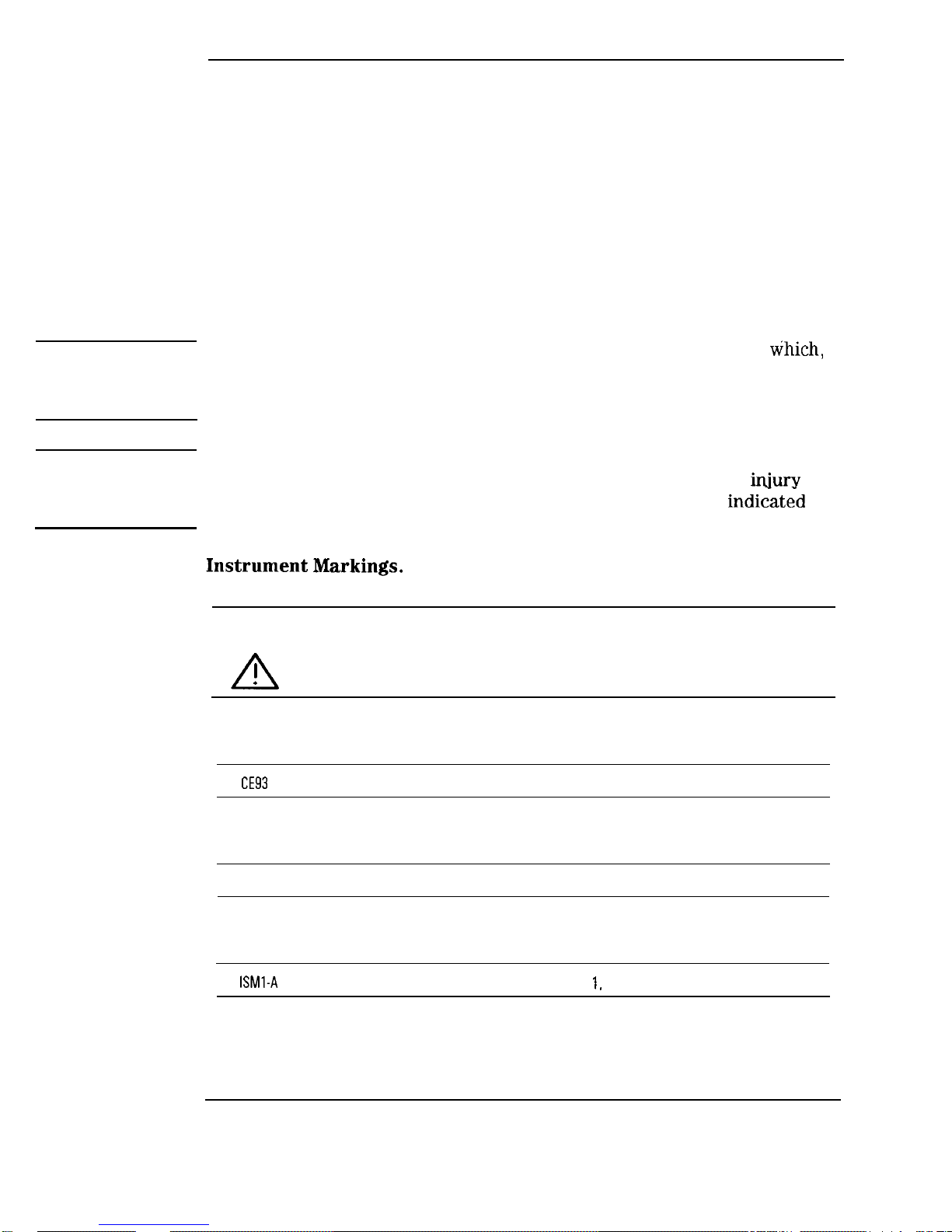
The following safety notes are used throughout this manual. Familiarize
yourself with each of the notes and its meaning before operating this
instrument.
CAUTION
WARNING
The caution note denotes a hazard. It calls attention to a procedure
if not correctly performed or adhered to, could result in damage to or
destruction of the instrument. Do not proceed beyond a caution note until
the indicated conditions are fully understood and met.
The warning note denotes a hazard. It calls attention to a procedure
which, if not correctly performed or adhered to, could result in
or
loss of life. Do not proceed beyond a warning note until the indicked
conditions are fully understood and met.
Markings.
Instruction
Manual
The
The instruction manual symbol. The product is marked with this symbol when it is necessary
for the user to refer to the instructions in the manual.
mark shows compliance with European Community 1993 standards.
The CSA mark is the Canadian Standards Association safety mark.
The
mark stands for Industrial Scientific and Medical Group
xii
Class A.
Page 13
General Safety Considerations
WARNING
WARNING
WARNING
CAUTION
Before this
switched on, make sure it has been properly
grounded through the protective conductor of the ac power cable to a
socket outlet provided with protective earth contact.
This is a Safety Class I product (provided with a protective earthing
ground incorporated in the power cord). Any interruption of the
protective (grounding) conductor, inside or outside the instrument, or
disconnection of the protective earth terminal can result in personal
injury.
No operator serviceable parts inside the instrument. Refer servicing to
qualified personnel. To prevent electrical shock, do not remove covers.
Any adjustments or service procedures that require operation of the
instrument with protective covers removed should be performed only by
trained service personnel.
For continued protection against fire hazard, replace line fuse only
with the same type and rating (F
The use of other fuses or
material is prohibited.
If this instrument is used in a manner not specihed by Hewlett-Packard Co.,
the protection provided by the instrument may be unpaired.
CAUTION
CAUTION
Always use the three-pronged ac power cord supplied with this instrument.
Failure to ensure adequate earth grounding by using this cord may cause
instrument damage.
This instrument has automatic selection input. Be sure the supply voltage is
within the speciEed range.
. . .
Page 14

How to Use This Guide
SHIFT FUNCTION
ANNUNCIATOR
This represents a key physically located on the
instrument.
This represents a shift function (blue text above
front panel keys).
Text in this font represents FREQUENCY,
MARKER/SWEEP/STATUS, and POWER displays.
Text in this font represents the annunciators that
are displayed in the lower portion of the sweeper
display.
Page 15
Performing
check
check
you
full
a
fails
power
1-5
check fails
1-6
step
also
a
also
1EE
also
Stepped Sweep
Millimeter Signal
(high power) sweepers ................
(standard power) sweepers
See also
.....................
a
..............
set up the sweeper ...............
set up the power meter
start the user flatness cal
a scalar analysis
set up
2-3
2-6
2-6
2-7
2-8
2-9
2-11
4-3
4-5
4-6
5-3
5-4
5-5
5-5
5-6
5-7
Page 16
set up
up
HP
5-7
5-8
5-8
7.
set up
set up
also
Also
Cables
slave
Setup
6-4
6-6
6-7
7-3
7-5
7-8
7-8
7-10
1EE
7-13
7-15
7-16
7-17
Display
7-18
7-23
7-25
7-26
7-26
7-27
Keys
8-3
8-4
8-6
8-8
8-11
Page 17
9.
Keys
........................
........................
.......................
(PULSE MODE
(FM MODE
(POWER LEVEL]
MODE
...................
....................
....................
. . . . . . . . . . . . . . . . . . . .
10-4
10-7
11-4
11-6
11-8
11-9
11-10
11-12
12-4
12-7
13-3
13-5
13-7
13-10
Keys
Keys
14-3
14-4
14-5
14-6
14-7
14-8
14-9
14-10
Page 18
Special
2
CW PEAKNG . . . . . . . .
ROSC
ROSC
FM
*SECURITY
FULL
LLIM
SCALE
15-6
15-7
15-8
15-9
15-10
Messages
The Error/Event Queue
Error numbers
Messages List
Messages
Command Error
Execution Error
Device-specific Error
Query Error
Specific
................
....................
...................
..................
................
....................
Messages
Self-test
16-3
16-4
16-5
16-7
16-7
16-13
16-19
16-21
16-23
16-23
16-24
16-25
16-28
16-32
16-32
16-33
16-35
16-36
Page 19
Mode
Sweep Mode
Leveled
Leveling
Options
Sweep
Power
(Level)
“C)
FM (0.05
kHz
Step
Page 20
1EE
1CP
AX2
W30
High
Source
Rack
Rack
Two
Output
Cover
W50
W52
W54
OB3
1BP
Regulatory
for
of
Service
Year
Year
Year MIL-STD
Noise
HP
Service
Service
Page 21

l-l. The UNLEV Annunciator Location ............. l-7
ALC Circuit Externally Leveled ..............
2-2. Typical Diode Detector Response at 25
.........
2-3. Leveling with a Power Meter ...............
2-4. Millimeter-wave Source Module Leveling ..........
2-5. Millimeter-wave Source Module Leveling Using a Microwave
4-1. Millimeter-wave Source Module Leveling ..........
4-2. Millimeter-wave Source Module Leveling Using a Microwave
Amplifier ......................
5-1. Creating a User Flatness Array ......... .....
5-2. Scalar Measurement System Setup ............
Master/Slave Setup ...................
Sweeper Connectors
7-2. Sweeper Connectors
Front Panel .............
Rear Panel .............
7-3. Auxiliary Interface Connector ...............
7-4. HP-B Connector and Cable ................
7-5. Interface Signals of the Source Module Connector ......
7-6. Sweeper Display ............... .....
7-7. Sweeper Display and LED Annunciators ..........
7-8. HP-B Address Switch Settings ..............
7-9. Instrument Language Switch Settings ...........
7-10. Clear Register Contents Settings .............
7-12. Power Cable and Line (Mains) Plug Part Numbers ......
Instrument State Group .................
The Markers Group ...................
12-1. The Sweep Group ....................
13-1. The Power Group ....................
14-1. The Entry Group ....................
15-1. The Instrument Group ..................
2-3
2-5
2-7
2-9
4-4
4-6
5-3
5-6
6-3
7-3
7-4
7-8
7-13
7-16
7-19
7-23
7-24
7-24
7-27
7-30
8-2
9-2
10-2
11-2
12-2
13-2
14-2
15-2
17-2. Typical Maximum Available Power ............
mode) .......................
17-6
17-7
Page 22

Contents
17-3. Typical Phase Noise (10
17-4. Dimensions
.......................
Carrier)
...........
17-12
17-17
Page 23

Pin Description of the Auxiliary Interface
Factory Preset Conditions
14-1. Step Sizes
.......................
................
.........
15-1. Special Functions for the HP 83750 Series Sweepers
15-2. FM Sensitivity When Using Source Modules
........
....
7-9
8-4
14-3
15-4
15-19
Page 24

1
Performing the Operator’s
Check
Page 25

Performing the Operator’s Check
The operator’s check consists of a series of tasks that, when completed, will
either assure you that your instrument is operating correctly, or will help
to point to problem areas if it is not. The operator’s check
performance to specifications.
The operator’s check should be performed on a weekly basis, or whenever
the integrity of the sweeper is in question.
To perform the operator’s check, the following tasks should be performed, in
order:
1. Run the full self-test.
2. Run peak power-tracking.
3. Check the maximum leveled power.
4. Check the output power.
not ensure
Page 26
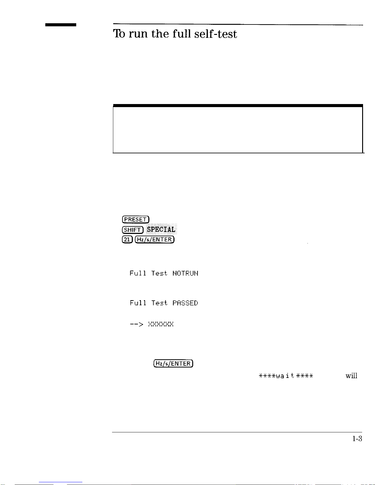
Attention!
All external cables [including HP-IB and BNC cables) must be disconnected from the sweeper prior to
running the full self-test. Failure to do so may cause self-test failures or lock-ups.
1. Disconnect all external cables prior to running the self-test.
2. Activate the FULL SELFTST special function by pressing the following
keys on the sweeper:
The message that appears in the MARKER/SWEEP/STATUS display is
one of the following:
Full self-test has not been performed
since the last time the line power was
turned on.
Full self-test has been performed and
passed all tests.
Full self-test has been performed, and
test XXXXXX was either the only test
that failed, or was the most significant
failure.
3. Press the
While the self-test
appear in the MARKER/SWEEP/STATUS display.
key again to initiate the self-test routine.
routine is running, a
message
Page 27

Performing the Operator’s Check
To run the full self-test
4. When the self-test routine is
a message will appear in the
MARKER/SWEEP/STATUS display. If the message does not say
refer to the section entitled “If You Have a
Problem” at the end of this chapter.
The full self-test is actually a series of tests performed to check different
instrument functions. If the sweeper fails just one test, the display shows the
title of the failed test. If the instrument fails more than one test, the test title
shown is the most signilicant failure.
1-4
Page 28
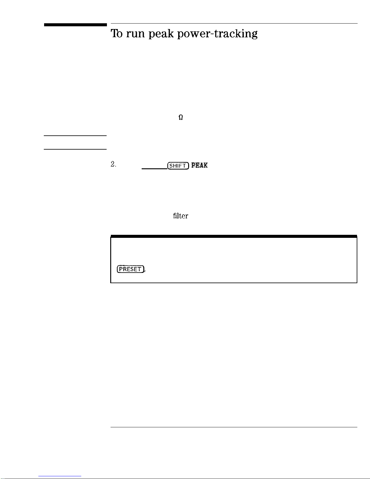
1. Before running peak power-tracking, make sure the RF OUTPUT is either
connected in a 50 0 system, or has a load on it, such as a power sensor or
attenuator.
CAUTION
For optimum power at all frequencies, do not run peak power-tracking with a
millimeter head connected to the sweeper.
Press (PRESET)
The MARKER/SWEEP/STATUS display shows the progression of the sweep
as the instrument adjusts the power-tracking.
When you run peak power-tracking (or autotracking), the instrument
optimizes its output power over the sweeper’s full frequency range by
tracking the output
NOTE
Peak power tracking takes approximately 1 to 3 minutes to complete, and can be aborted by pressing
if necessary.
P&W .
with the RF source output.
1-5
Page 29
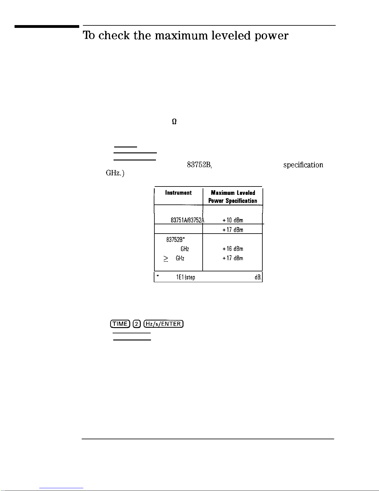
1. Before checking maximum leveled power, make sure the RF OUTPUT is
either connected in a 50
system, or has a load on it, such as a power
sensor or attenuator.
2. Press [PRESET).
3. Press [POWER LEVEL) and enter the specified maximum leveled power for
your instrument. (For an HP
set the power to the
< 2
for
HP
HP 837518”
HP
< 2
2
Option
[step attenuatorl, reduce by 1
4. Make sure the UNLEV annunciator is not lit at any time. The UNLEV
annunciator is located in the POWER display area. (See Figure l-l.)
5. Press
to change the sweep time to 2 seconds.
6. Press [SINGLE TRIG] and make sure the UNLEV annunciator does not come
on at any point during the sweep. (If the annunciator comes on, it
indicates the instrument is unleveled.) The UNLEV annunciator is located
in the POWER display area. (See Figure l-l.)
1-6
Page 30

Performing the Operator’s Check
To check the maximum leveled power
000 0 000 0 00000
00
00
The HP
7. Press the following keys to set a sweep range of 2
power level of 17
[POWER
8. Press @NGLE
0 0 000 0 00000
0 0 000 0 00000
Figure l-l. The UNLEV Annunciator location
83752B
000000
sweepers have a power specification that is split at 2
(or 16
(or
and make sure the UNLEV annunciator does not come
for instruments with option
0
to 20
and a
on at any point during the sweep. (If the annunciator comes on, it
indicates the instrument is unleveled.) The UNLEV annunciator is located
in the POWER display area. (See Figure l-l.)
Page 31

1. Connect the equipment as shown.
POWER METER
POWER SENSOR ADAPTER
Figure 1-2. Connections for Checking Output Power
2.
Press (PRESET_).
3. Press ccw)
4. Press
LEVEL) and enter the specified power for the CW frequency
SYNTHESIZED SWEEPER
you set. Refer to the following table. Terminate the power level entry by
pressing
Instrument
HP
HP 837518”
HP 837528”
< 2
2
Option
Maximum leveled
Power Specification
lstep attenuetorl, reduce by 1
Page 32

Performing the Operator’s Check
To check the output power
5. Set the power meter calibration factor to the value listed on the power
sensor that corresponds to the frequency you set.
6. Verify that the measured output power meets the instrument specification.
l If the measured value is less than the specihed power, turn the front
panel knob until the value measured is at least the speciEed power level.
l Make sure that the UNLEV annunciator doesn’t light. (If the annunciator
does light, this indicates an unleveled condition.)
7. Repeat steps 3 through 6 for the following setting(s):
2.5
1.5
50 MHz
for HP
for HP
instruments only
instruments only
Page 33

If you have a problem while performing the operator’s check, check the
following list of commonly encountered problems. If the problem you have
encountered is not here, contact the nearest Hewlett-Packard office for
assistance.
The self-test has failed if the message that appears when it is done, is
anything except
q Make sure all external cables are disconnected from the sweeper and run
the self-test again.
q If the test still fails, send the instrument to an HP service center for repair,
including a description of the failed test and any other error messages.
NOTE
If you need to ship your sweeper, remove the front handles (if so equipped) and use the original
packaging (or comparable).
Full Test.
Page 34

Performing the Operator’s Check
q Make sure that the RF OUTPUT connector was terminated before the peak
power-tracking sequence was run, and before the maximum leveled power
check.
q Make sure the power you entered in steps 2 and 5 of the maximum leveled
power check procedure are correct for your particular instrument.
q
the measured value of power in step 6 of “To check the output power” is
than the specified power, turn the front panel knob counterclockwise
until the value measured equals the specified power. Note the sweeper’s
front panel reading and use this value to repeat the maximum leveled
power check.
q If the check still fails, contact the nearest Hewlett-Packard office for
assistance.
NOTE
If you need to ship your sweeper, remove the front handles
packaging (or comparablel.
so equipped) and use the original
Page 35

2
Externally Leveling the
Sweeper
Page 36

Externally Leveling the Sweeper
In externally leveled operations, the output power from the sweeper is
detected by an external sensor. The output of this detector is returned to the
leveling circuitry, and the output power is automatically adjusted to keep
power constant at the point of detection.
2-2
Page 37

1. Connect the equipment as shown in Figure 2-1.
SYNTHESIZED SWEEPER
DIRECTIONAL COUPLER
OR POWER
SPLITTER)
Figure 2-1. ALC Circuit Externally leveled
2. Press
shows
MODE
repeatedly until the MARKER/SWEEP/STATUS display
Diode. Note that the EXT ALC annunciator is lit.
3. Enter the coupling factor by selecting
the desired number.
OUTPUT
EXT CAL and then entering
2-3
Page 38

Externally Leveling the Sweeper
leveling with detectorslcouplerslsplitters
NOTE
The coupling factor (in
leveled power
locations of P lev and P det. After the coupling factor has been entered, the front panel knob
may be used to fine tune the displayed power to equal the actual leveled output power (P levl.
Figure
illustrates a typical setup for external leveling. When externally
is defined by the equation
detected power
Refer to Figure ‘2-1 for
leveled, the power level feedback is taken from the external negative detector
input rather than the internal detector. This feedback voltage controls the
ALC system to set the desired RF output.
Figure 2-2 shows the input power versus output voltage characteristics for
typical
diode detectors. From the chart, the leveled power at the diode
detector input resulting from any external level voltage setting may be
determined. The ALC feedback voltage present at the output of the detector
must be between -0.2
corresponds to a detector input of approximately -35
and -0.5
For a typical
diode detector, this
to
(See
Figure 2-2.)
2-4
Page 39

Externally Leveling the Sweeper
leveling with detectors/couplers/splitters
dBV
dBV
dBV
dBV
dBV
dBV
dBV
dBV
dBV
DETECTOR INPUT POWER,
Figure 2-2. Typical Diode Detector Response at 25
dBV
dBV
2-5
Page 40

Externally leveling the Sweeper
leveling with detectors/couplers/splitters
Some external leveling applications require low output power from the
sweeper. The sweeper automatically uncouples the attenuator from the ALC
system for
the UNCPLD annunciator is lit.
For example, leveling the output of a 30
10
leveled. At some frequencies this level is beyond the range of the ALC
modulator alone. If so, the UNLEV warning message is displayed. Inserting 40
of attenuation results in an ALC level (power level + attenuator value) of
0
AM or other functions that vary the power level.
The ALC level should be greater than or equal to -10
sweepers (standard power), and -5
power). Adjust the attenuator so that the ALC level is within the specified
power range of your sweeper. For an “A” model sweeper, this is achieved by
using attenuation equal to the tens digit of output power. Example: for a
desired sweeper output power of -43
which is well within the range of the ALC. This gives a margin for
external leveling points. Note that in external leveling modes,
requires the output of the sweeper to be around -40
for “B” model sweepers (high
gain amplifier to a level of
do the following:
for “A” model
when
Press
2. Set the attenuator to 40
SPECIAL
press
To obtain flatness corrected power refer to the chapter entitled “Creating User
Flatness Correction Arrays,
2-6
later in this manual.
Page 41

Leveling with a power meter is similar to leveling with a diode detector.
1. Set up the equipment as shown in Figure 2-3. Be sure to set the power
meter to the correct manual range mode for the output power setting at
which you are leveling.
OUTPUT
POWER
METER
POWER SENSOR
I
Figure 2-3. leveling with a Power Meter
2. Press
shows
3. Select
MODE $J repeatedly until the MARKER/SWEEP/STATUS display
EXT CAL
Note that the EXT ALC annunciator is lit.
enter the coupling factor of the coupler.)
(If a directional coupler is used,
2-7
Page 42

Externally leveling the Sweeper
leveling with a power meter
The coupling factor is defined by the equation
leveled power
locations of P lev and P det. After the coupling factor has been entered, the front panel knob
may be used to fine tune the displayed power to equal the actual leveled output power fP lev).
detected power
Refer to Figure 2-1 for
4. If the power meter and the sweeper power setting don’t agree, set the
coupling factor step size to 10
and then use the
keys to adjust
the coupling factor up or down until the power meter and the sweeper
power setting agree.
5. Select the sweep tune by pressing
and then entering the desired
sweep rate.
Due to the settling time required by power meters, it is recommended to use a 40 second sweep rate.
Unlike detector leveling, power meter leveling provides calibrated power out
of the leveled RF port.
To obtain flatness corrected power refer to “Creating User Flatness Correction
Arrays,
2-8
later in this manual.
Page 43

Millimeter-wave source module leveling is similar to power meter leveling,
except that a slow sweep time is not required. Figure 2-4 and Figure 2-5
illustrate the setups for leveling with a mm-wave source module.
Figure 2-4 illustrates the setup that is used with the HP
HP
maximum specified power. The interface extender cable
5062-7202) allows the source module to be positioned in front of the sweeper.
(high power models). No external amplifier is required to obtain
and
part number
OUTPUT
ADAPTER
REQU
Figure 2-4. Millimeter-wave Source Module leveling
MM-WAVE SOURCE
MODULE
2-9
Page 44
Externally leveling the Sweeper
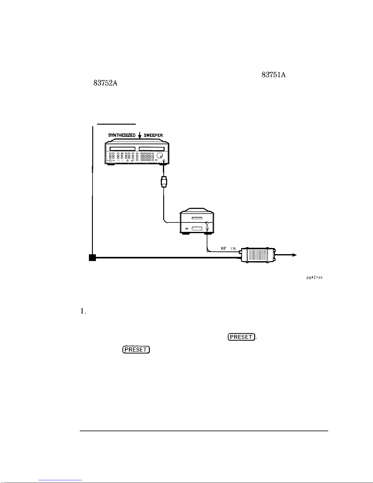
Figure 2-5 illustrates the setup that is used with the HP
HP
(standard power models). An external amplifier is required to
obtain maximum specified power.
SOURCE MODULE
I NSERFACE
RF OUTPUT
ADAPTER
(IF REQUIRED)
INTERFACE
EXTENDER
CABLE
MICROWAVE
AMPLIFIER
RF IN
RF OUT
W-WAVE SOURCE
MODULE
and
LEVELED
OUTPUT
Figure 2-5. Millimeter-wave Source Module leveling Using a Microwave Amplifier
Turn the sweeper line power off.
2. Set up the equipment as shown in Figure 2-4 or Figure 2-5.
3. Turn the sweeper line power on and press
4. When the
key is pressed, the sweeper configures itself for source
module operation, and all of the ALC data necessary to communicate
properly with the sweeper is exchanged via the rear panel SOURCE
MODULE INTERFACE. Note that the EXT ALC annunciator is lit, and that
the POWER display shows the millimeter head output power.
2-10
Page 45

Externally leveling the Sweeper
To obtain flatness corrected power refer to “Creating User Flatness Correction
Arrays,
later in this manual.
2-11
Page 46

3
Generating a Stepped
Sweep
Page 47

Generating a Stepped Sweep
To generate a stepped sweep, perform the following steps:
1. Press (PRESET).
2.
Select the desired
and IsTopl frequencies.
Select the desired number of points by pressing
entering the desired number.
Press
5. Press the
SWEEP MODE
.
key. The MARKER/SWEEP/STATUS display should read
and the STEP annunciator should be lit.
6. The instrument is now running in stepped sweep mode.
NOTE
The stepped sweep time is calculated by the following formula:
Time
stepped sweep time can be changed in one of two ways:
l By changing the dwell time. (Press
l By changing the number of points. (Press
Dwell Time *Number of Points. Therefore the
while in stepped sweep
POINTS and
3-2
Page 48

4
Generating a Millimeter
Signal
Page 49

Generating a Millimeter Signal
If your sweeper was ordered with Option lEE, you have the capability of
using HP 83550 series millimeter head source modules with the sweeper. The
interface extender cable (HP part number 5062-7202) that is provided with all
option
sweeper.
After a source module is connected to the sweeper via the SOURCE MODULE
INTERFACE connector, the sweep will automatically configure itself for source
module operation when the line power is cycled, when the sweeper is preset,
or when a register is recalled.
sweepers allows the source module to be positioned in front of the
4-2
Page 50

Figure
HP
Turn the sweeper line power off, and connect the equipment as shown in
Figure
2. Turn the sweeper on, and press
3. The sweeper automatically configures itself for source module operation
when the
shows the equipment setup for using a millimeter head with your
or HP
key is pressed.
4-3
Page 51

Generating a Millimeter Signal
Using millimeter heads with “B” model
OUTPUT
ADAPTER
(high power) sweepers
Figure
MM-WAVE SOURCE
MODULE
Source Module leveling
4-4
Page 52

Figure 4-2 shows the equipment setup for using a millimeter head with
your HP
maximum specihed power.
1. Turn the sweeper line power off, connect the equipment as shown in
Figure 4-1.
2. Turn the sweeper on, and press
3. The sweeper automatically configures itself for source module operation
when the (PRESET_) key is pressed.
or HP
An external amplifier is required to obtain
4-5
Page 53

Generating a Millimeter Signal
SOURCE MODULE
INTERFACE
RF OUTPUT
ADAPTER
(IF REQUIRED)
NTERFACE
MICROWAVE
AMPLIFIER
RF IN
SOURCE
MODULE
LEVELED
OUTPUT
Figure 4-2. Millimeter-wave Source Module leveling Using a Microwave Amplifier
To obtain flatness corrected power refer to “Creating User Flatness Correction
Arrays,” later in this section.
4-6
Page 54

5
Creating User Flatness
Arrays
Page 55

Creating User Flatness Arrays
This chapter explains how to create user flatness correction arrays, which
calibrate the power level at a remote test port. Two examples are provided:
l The first example shows the basic setup and steps to create a user flatness
array.
l The second example shows how to set up a scalar analysis measurement
using a user flatness correction array.
5-2
Page 56

In this example an HP
the interface bus
power meter controlled by the sweeper through
is used to enter the correction data into a flatness
array.
Figure 5-l shows a typical system setup. The setup shown assumes that if
the setup has an external leveling configuration, that the steps necessary to
correctly level have been taken. Refer to Chapter 2, “Externally Leveling the
Sweeper,
for information on external leveling.
IN
I
I
I
AND OTHER
i
RF
I
OUTPUT
INPUT
PORT
I
,
I
TEST
----------
Figure
TEST PORT
POWER SENSOR
Creating a User Flatness Array
5-3
Page 57

Creating User Flatness Arrays
Creating a user flatness array
Connect the equipment as shown in Figure 5-l. Do not connect the power
1.
sensor to the system yet. Press
If a frequency range other than the full range of the instrument is desired,
2.
use the
If external cables and/or devices are used between the sweeper leveling
3.
and
on the sweeper.
keys to input the desired frequency range.
point (the RF OUTPUT if internally leveled, or the coupler/splitter output
if externally leveled) and the remote test port, the nominal (average) loss
of these components should be entered as an offset. To enter the power
offset, press
nominal loss from the leveling point of the sweeper to the test port. (For
example, if there is a 6
port, enter a power offset of
OFFSET (in the POWER key group) and then enter the
loss from the leveling point to the remote test
Set the power level to the level desired at the test
4.
[POWER LEVEL) and entering the desired number.
5.
Select
SPECIAL
Use the @j
the type of power meter you will be using.
6.
Select (SHIFT) SPECIAL
Enter the HP-IB address of the
by pressing,
keys to select
for this example.)
power meter you will be using for the calibration. (Thirteen is the default
address for power meters.)
7.
Press
a. Select whether to calibrate over
FLTNESS
(correction points will be
linearly spaced over the selected Start/Stop frequency range, or
Bard (correction points will be linearly spaced over the full frequency
range of the instrument). Use the
keys to make your selection,
then press [Hz/s/ENTER).
b. Select the number of correction points, using the keypad for your entry
(valid entries range from 2 to Sol), then press
c. The MARKER/SWEEP/STATUS display should now read:
--
11
5-4
Page 58

Creating User Flatness Arrays
Creating a user flatness array
l Zero and calibrate the power meter/sensor.
l Enter the appropriate power sensor calibration factors into the power
meter.
l Enable the power meter/sensor
on the HP
l Connect the power sensor to the point where corrected
(See Figure
l
The MARKER/SWEEP/STATUS display should still read:
l Press
power meter refer to its operating and service manual.
1.)
PM -- ENTER.
to start the calibration. The display will show each
factor array. For operating information
is desired.
correction point’s frequency and power as it is measured.
l When the calibration is finished, the flatness correction is automatically
turned on, and the FLTNESS ON LED annunciator is lit on the front panel
of the sweeper. Power correction will be linearly interpolated between the
measured correction points. The POWER display will
the test
port power.
Attention!
Before doing anything else, save this calibration in one of the instrument’s registers. If the calibration
has not been saved, and the instrument is preset, a register is recalled, or the power offset is
changed, the calibration will be lost. To save the calibration, press
of the instrument register you wish to save it in.
and then enter the number
5-5
Page 59

Page 60

Creating User Flatness Arrays
Creating a user flatness array for use in a scalar analysis measurement
1. Connect equipment as shown in Figure 5-2. Do not connect the power
sensor to the system yet.
2. Press (PRESET) on the scalar analyzer (HP 8757).
3. If a frequency range other than the full range of the instrument is desired,
use the
frequency range.
4. If external cables and/or devices are used between the sweeper leveling
point (the RF OUTPUT if interrmlly leveled, or the coupler/splitter output
if externally leveled) and the remote test port, the nominal (average) loss
of these components should be entered as an offset. To enter the power
offset, press
nominal loss from the leveling point of the sweeper to the test port. (For
example, if there is a 6
port, enter a power offset of
and
OFFSET (in the POWER key group) and then enter the
keys on the sweeper to input the desired
loss from the leveling point to the remote test
5. Set the power level to the level desired at the tat port by pressing
(POWER LEVEL] and entering the desired number.
Select
the type of power meter you will be using.
Select (SHIFT)
power meter you will be using for the calibration. (Thirteen is the default
address for power meters.)
1. On the analyzer, set up the appropriate measurement (i.e. gain for an
amplifier). Calibrate the measurement (thru and short/open calibration).
Press
sweeper parameters in storage register 1.
SPECIAL (12)
(Hz/s/ENTER_). Enter the
(iJ on the analyzer to store the analyzer configuration and
Use the
keys to select
for this example.)
address of the
5-7
Page 61

Creating User Flatness Arrays
Creating a user flatness array for use in a scalar analysis measurement
Attention!
Do not proceed until the HP 8757 system interface is turned off by pressing
pressing softkeys, MORE,
1. Zero and calibrate the power meter/sensor.
2. Enter the appropriate power sensor calibration factors into the power
meter.
3. Enable the power meter/sensor cal factor array. For operating information
on the HP
power meter refer to its operating and service manual.
MODE, and
on the analyzer.
Then by
I
4. Connect the power sensor to the point where corrected power is desired.
(See Figure 5-2.)
1. On the sweeper, press
a. Select whether to calibrate over St>arSt.op (correction points will be
5-8
linearly spaced over the selected Start/Stop frequency range, or
(correction points will be linearly spaced over the full frequency
range of the instrument). Use the
then press (Hz/s/ENTER).
CAL
keys to make your selection,
11
Page 62

Creating User Flatness Arrays
b. Select the number of correction points, using the keypad for your entry.
Valid entries range from 2 to 801, then press
c. The MARKER/SWEEP/STATUS display should now read:
PM --
2. Press
to start the calibration. The display will show each
correction point’s frequency and power as it is measured.
3. When the calibration is finished, the flatness correction is automatically
turned on, and the FLTNESS ON LED annunciator is lit on the front panel
of the sweeper. Power correction will be linearly interpolated between the
measured correction points.
4. Save the calibration by pressing
Attention!
If the calibration is not saved in an instrument register, and the sweeper or analyzer is preset, a
register is recalled, or the power offset is changed, the calibration will be lost. Reactivating the
SYSINTF on the analyzer will also cause a preset and loss of the calibration. Be sure to save the
calibration as described in the previous step before continuing.
(iJ on the sweeper.
Press the softkey SYSINTF
preset.
2. Press
3. Devices can now be tested.
OFF on the analyzer and the sweeper will
(iJ to pull up the calibration.
5-9
Page 63

6
I
Operating a Master/Slave
Setup
Page 64

Operating a Master/Slave Setup
Two
capabilities. Two synchronously tracking sweepers can be configured as a
“master/slave” pair for mixer characterization or inter-modulation distortion
measurements. The swept frequency accuracy allows control of the sweepers
at Exed- or swept-frequency offsets.
To implement master/slave operation, configure the sweepers as shown in
Figure 6-l. The master sweeper generates the 10 MHz frequency reference
for both sources. The source synchronization cable (HP part no. 83750-60059)
must be connected between the auxiliary interface connectors on the rear
panels of the sweepers.
When conEguring a two-tone measurement system, the slave does not need
to interface with any instruments other than the master. The master should
interface with the display device (scalar analyzer or oscilloscope, for example)
as if it were a stand-alone sweeper.
83750 series sweepers can be configured for two-tone measurement
6-2
Page 65

Operating a Master/Slave Setup
Figure
“SLAVE”
SYNTHESIZED
SWEEPER
Master/Slave Setup
6-3
Page 66

1. Press
2. Activate the master mode by pressing
If the display does not read
once to set the control mode to master.
3. Set the desired frequencies by using the
keys, or the
NOTE
It is recommended that the master and slave sweepers frequencies not differ more than 5
point in the sweep. If this requirement is not met, it is possible for unlocks to occur. If frequency
offsets greater than 5
unlocks.
4. Set the desired power level using the (POWER LEVEL] key.
are required, it may be necessary to reduce the sweep speeds to eliminate
key.
(SPECIAL)
then press the
keys, the
key
at any
5. Set the desired sweep time using the (TIME) key. (The recommended
minimum sweep time for master/slave mode is 100 ms.)
NOTE
The master and slave sweepers must have identical sweep times. Therefore, the value entered here
must also be entered into the slave sweeper.
6-4
Page 67

Operating a Master/Slave Setup
To set up the master sweeper
Set the sweep mode to stepped by pressing
then pressing the
Set the number of points by pressing
SWEEP MODE $ , and
key until the display reads:
POINTS and entering the
desired number of points.
NOTE
The master and slave sweepers must have identical sweep mode, number of points, and sweep time
settings. Therefore, the values entered here must also be entered into the slave sweeper.
.
6-5
Page 68

1. Press (PRESET).
2. Activate the slave mode by pressing (SHIFT)
Press the
key until the display reads
t- 1
3. Set the desired frequencies by using the
NOTE
It is recommended that the master and slave sweepers frequencies not differ more than 5
point in the sweep. If this requirement is not met, it is possible for unlocks to occur. If frequency
offsets greater than 5
unlocks.
4. Set the desired power level using the
are required, it may be necessary to reduce the sweep speeds to eliminate
LEVEL] key.
keys, the
at any
5. Set the sweep time to the same value as the master sweeper using the
key. (The recommended minimum sweep time for master/slave
mode is 100 ms.)
Set the sweep mode to stepped by pressing (SHIFT)
then pressing the
7. Set the number of points to the same value as the master sweeper by
pressing
6-6
MODE
key until the display reads:
POINTS and entering the number of points.
, and
Page 69

For a
“Multi-pin Connectors” section of Chapter 7, “Front/Rear Panel.”
description of the source synchronization cable, see the
6-7
Page 70

7
Front/Rear Panel
Page 71

Front/Rear Panel
This chapter contains detailed information on various aspects of the sweeper
front and rear panel. Information on the following can be found in this
chapter:
Connectors
l Display
l HP-B Lang/Address Switch
l Knob
l Line Power Switch
l Power Cables
7-2
Page 72

00
00
00
0
0
0
0
la
,
Figure 7-1. Sweeper Connectors
OUTPUT
Front Panel
7-3
Page 73

Front/Rear Panel
Connectors
OUTPUT
1EE
7-4
Figure 7-2. Sweeper Connectors
Rear Panel
Page 74

Front/Rear Panel
Connectors
10 MHz REF IN
10 MHz REF
OUT
ALC IN
AM INPUT
FM
This rear panel female BNC connector accepts a -5 to + 10
signal from an external time base reference which is
within
MHz. The nominal input impedance is 50
ppm of 10 MHz or any sub-multiple down to 1
This connector
detects when a valid reference signal is connected to it and
automatically switches from internal to external reference
operation.
This rear panel female BNC connector provides a nominal
signal level of 0
and output impedance of 50
The
accuracy is determined by the tune base used.
This front panel female BNC connector is used for external
power meter leveling or external negative detector leveling.
The damage level is
The nominal input impedance is
100
This rear panel female BNC connector accepts the amplitude
modulating signal input when External AM is enabled. The
nominal input impedance is 3.5
The damage level is
v.
This rear panel female BNC connector accepts the frequency
modulating signal input when DC or AC FM is enabled. The
nominal input impedance is 1
The damage level is
v.
PULSE IN/OUT
This rear panel female BNC connector can be used as
either an external pulse input or output for internal pulse
modulation. In either case, it is TTL level compatible and
has a nominal impedance of 5
A TTL high level (>
enables the selected power level
The damage level is
to be at the RF OUTPUT connector, while a TTL low level
turns the RF off.
7-5
Page 75

Front/Rear Panel
Connectors
STOP SWEEP
SWEEP OUT
This rear panel female BNC connector causes a sweep to be
stopped when this input is pulled low. Retrace does not
occur, and the sweep resumes when this input is pulled
high. The open circuit voltage is TTL high and is internally
pulled low when the instrument stops its sweep. The
damage level is
+ 10 V or
-4
These front and rear panel female BNC connectors provide
a voltage range of 0 to + 10 V. When the instrument is
sweeping, the SWEEP OUT ranges from 0 V at the beginning
of the sweep and + 10 V at the end of the sweep regardless
of the sweep width. In CW mode, the SWEEP OUT ranges
from 0 V at the sweeper minimum frequency to + 10 V
at the specifled maximum frequency, with a proportional
voltage for frequencies between the specified minimum and
maximum. When the sweeper is in manual sweep operation,
the SWEEP OUT voltage is a percentage of the span. The
nominal output impedance is 100
into a high impedance load.
When used with the HP
The typical accuracy is
scalar analyzer in
ramp-sweep mode, the rear panel output is a series of 0 to
+ 10 V pulses similar to the Trigger Output.
TRIGGER
INPUT
TRIGGER
OUTPUT
OUTPUT
7-6
This rear panel female BNC input is activated on a TTL
rising edge. It is used to externally initiate an analog sweep
or to advance to the next point in stepped sweep mode. The
damage level is
This rear panel female BNC connector outputs a 1
+ 10 V or
-4
wide
negative-going TTL pulse at 1601 points evenly spaced
across an analog sweep, or at each point in stepped sweep
mode. When used with the HP
scalar analyzers, the
number of pulses per sweep (in analog sweep mode) is
determined by the number of HP 8757 trace points.
This rear panel female BNC connector supplies a voltage
that is proportional to the RF output frequency, which can
be configured to any desired sensitivity and offset within
a
minimum load impedance is 2
V range. The default setting is 0.5
The typical accuracy is
mV
The
Page 76

Front/Rear Panel
Connectors
AXIS
This rear panel female BNC connector supplies a positive
rectangular pulse (approximately
V into 2
during
the retrace and band switch of the RF output when the
instrument is sweeping. This output also supplies a -5
V pulse when the RF output is coincident with a marker
frequency.
7-7
Page 77

Front/Rear Panel
Connectors
AUXILIARY INTERFACE This connector provides special control signals used in master/slave interface
operation with another source, and in other special-purpose applications. This
connector is a
AUXILIARY INTERFACE
D-subminiature receptacle located on the rear panel.
SOURCE SYNCHRONIZATION
(HP P.N. 8375040059)
Figure 7-3. Auxiliary Interface Connector
CABLE
7-8
Page 78

Table 7-1. Pin Description of the Auxiliary Interface
Front/Rear Panel
Connectors
Pin
1
2 Z-Axis Blanking/Markers out
3
4
5
6
1
8
9
10 Rear Panel Control 1
11
12
13
14 Low Marker out
15
16
17 Rear Panel Control 2
18
19 Digital Ground
20 No Connection
21
22 No Connection
23 low Source Settled
24
25
Or
Alternate Sweep Out out
Spare
Rear Panel Control 3
low Stop Sweep
v out
Digital Ground
Low Divider-Sync
External Trigger
Rear Panel Control 0
Retrace
Alternate Sweep In
Stop Sweep
Rear Panel Control 4
Sweep Output
No Connection
low Source Settled
Spare
to 10 V pulses when used with a HP 87570 scalar analyzer.
Function
In
TTL
In
TTL
In
out
out TTL
TTL
out
In TTL
out
out
level
BlankMarker- -5 V
Gnd
to 10 V ramp”
Gnd
V
v
v
v
Page 79

Front/Rear Panel
Connectors
HP-II
This connector allows the sweeper to be connected to other instruments or
devices on the interface bus. Details of this cable are shown in Figure 7-4.
part numbers for various HPIB cables that are available are shown in the
table following the figure.
HP-IE
12
RL 1
0
Figure 7-4. HP-IB Connector and Cable
7-10
HP-IB Interface Cables Available
Page 80

Front/Rear Panel
Connectors
As many as 14 HP-B instruments can be connected to the sweeper (15
total instruments in the system). The cables can be interconnected in a star
pattern (one central instrument with the
cables emanating from that
instrument like spokes on a wheel), or in a linear pattern (like boxcars on a
train), or a combination of the two. There are certain restrictions that must
be followed when interconnecting instruments:
l Each instrument must have a unique HP-B address, ranging from 0 to 30
(decimal). Refer to
in the “Instrument State Keys” chapter for information on
Lang/Address Switch” later in this chapter, or
setting the sweeper HP-B address.
l In a two-instrument system that uses just one HP-B cable, the cable length
must not exceed 4 meters (13.2
l When more than two instruments are connected on the bus, the cable
length to each instrument must not exceed two meters (6.6 ft).
l The total cable length between all instruments must not exceed 20 meters
(65 ft).
Hewlett-Packard manufactures HPIB extender instruments (Models HP
and HP
that overcome the range limitations unposed by
the cabling rules. These extenders allow twin pair cable operation up to 1 km
(3,280
service offices can provide additional information on the
and telephone modem operation over any distance. HP sales and
extenders.
7-11
Page 81

Front/Rear Panel
Connectors
The codes next to the
connector, illustrated in Figure 7-4, describe
the HP-IB electrical capabilities of the synthesizer, using IEEE Std. 488-1978
mnemonics (HP-IB, GP-IB,
and RX-625 are all electrically
equivalent). Briefly, the mnemonics translate as follows:
Acceptor Handshake, complete capability.
Talker; capable of basic talker, serial poll, and unaddress if
MLA.
TEO
Extended address; no capability.
Listener, capable of basic listener, and unaddress if MTA.
LEO
Listener, Extended address; no capability.
Remote Local, complete capability.
Parallel Poll, no capability.
Device Clear, complete capability.
Device Trigger, complete capability.
CO, 1, 2, 3, 28
Controller capability options; CO, no capabilities; Cl, system
controller;
send IFC and take charge;
send REN;
send I. F. messages.
El
These codes are described completely in the IEEE Standard 488 (1978)
IEEE Standard Digital Interface
identical ANSI Standard MCl. 1.
7-12
Electrical specihcation indicating open collector outputs.
Programmable Instrumentation
or the
Page 82

Front/Rear Panel
Connectors
SOURCE MOOULE This connector sends and receives digital and analog signals to and from an
INTERFACE
Only)
HP 83550Series millimeter-wave source module. With the source module
connected, the sweeper assumes the characteristics of the source module.
RESERVED5
MOD
MOD
MOD Cl
DIG GND
Figure 7-5. Interface Signals of the Source Module Connector
The codes indicated in Figure 7-5 translate as follows:
MOD DO
Source module data line zero. Signals MOD DO through
MOD
are the millimeter source module data bus lines
(bidirectional).
RTN
SENSE
RESERVED
MOD
MOD D2
MOD D3
MOD CO
MOD Cl
Data line one.
Data line two.
Data line three.
Source module control line zero. Signals MOD CO and MOD
Cl are the control lines for the read/write to and from the
millimeter source module.
Control line one.
7-13
Page 83

Front/Rear Panel
Connectors
MOD SENSE
L MOD RF OFF
EXT
RET
EXT LVL
NOTE
Source module sense. A 1
current is injected on this line
by the millimeter source module to indicate its presence.
This signal always equals 0 V.
Low = RF off. Source module RF is turned off.
Source module external leveling return.
Source module external leveling input, from the millimeter
source module.
Internal
to the millimeter source module.
Power supply. Range is -14.25 to -15.45 V.
(See note below.)
Power supply. Range is + 14.25 to + 15.45 V.
(See note below.)
Power supply. Range is +7.50 to +8.45 V. (See note below.)
Power supply. Range is
to +5.40
(See note below.)
The values for the four power supplies above are valid when a millimeter head is connected. With no
load on the connector, the values would be:
15 v supply:
+ 15 v supply:
+
v supply:
+ 5 v supply:
DIG GND
RTN 0.5
ANLG GND
-14.4 to -15.45 v
v to
v to
v to
v
v
v
Digital ground.
return.
Analog ground return.
RET
7-14
Page 84

Front/Rear Panel
Connectors
The standard front panel RF OUTPUT connector is a precision 3.5 mm male
connector. When Option
is installed, this front panel connector is a
ruggedized Type-N connector. The nominal source impedance is 50
When making connections to this connector, carefully align the center
conductor elements, then rotate the knurled barrel while mating components
remain still. Tighten the barrel until Iirm contact is made.
care when working with this connector. If the connector is mechanically
degraded in any way, high frequency losses can occur. Refer to application
note 326, Coaxial
number
1566) for more information.
Principles of Microwave Connector Care
part
7-15
Page 85

The sweeper front panel display contains two areas (Frequency, and
Marker/Sweep/Status and Power) for displaying the current operating
parameters of the sweeper. Front panel annunciators show the status of
several of the sweeper functions and settings.
FREQUENCY DISPLAY
MARKER/SWEEP/STATUS
DISPLAY
Figure 7-6. Sweeper Display
POWER DISPLAY
Page 86

Front/Rear Panel
Display
The left-hand display is labelled FREQUENCY and is used exclusively to
show information about frequencies being generated. (Information about
markers is not pertinent to generated frequencies and is not displayed here.)
In Start/Stop and CF/Span sweep modes, the left display has two separate
fields of 11 characters each, whose contents depend on the instrument mode.
Two blank spaces separate the two fields. Frequencies are displayed using
eight signihcant digits, followed by a three-character frequency unit
MHz, or
number being displayed in the range of 1 to 999.99999, and digits below 1
resolution are not shown. Leading zeros are suppressed.
The decimal multiplier is changed automatically to keep the
In CW mode, there is one 24-character field. Frequencies are displayed using
up to 11 significant digits, followed by a three-character frequency unit
MHz, or
The decimal multiplier is changed automatically to keep the
number being displayed in the range of 1 to 999.99999, and digits below 1 Hz
resolution are not shown. Leading zeros are suppressed.
NOTE
or ,
The decimal separator (either .
to the “Special Functions” chapter for more information.
can be changed by selecting Special function number 18. Refer
7-17
Page 87

Front/Rear Panel
Display
The right-hand display is divided into two fields, although there is no physical
separation between them. (Normally, one blank space is inserted between
the left and right Eelds. When some features are accessed, however, all 24
characters of the right display can be used.)
The left Eeld is labelled MARKER/SWEEP/STATUS, and is used to show a
variety of information including marker frequencies, sweep time, and general
instrument status. Sixteen characters are reserved for this Eeld, including any
units displayed.
The right Eeld is labelled POWER, and displays the power level in
It is
seven character cells wide. Exed format.
NOTE
When operating the sweeper in a secure environment, the display can be blanked so that the sweeper
parameters and status cannot be viewed. For more information, refer to the “Special Functions”
chapter of this manual.
I
7-18
Page 88

DISPLAY
ANNUNCIATORS
Front/Rear Panel
Display
LED
ANNUNCIATORS
Figure 7-7. Sweeper Display and LED Annunciators
The front panel annunciators show the status of several of the sweeper
functions and settings. Refer to Figure 7-7. Notice that there are two types of
annunciators: display and LED.
A display annunciator is not visible if its associated function is not active or
selected. For example, if external pulse modulation is currently selected, the
EXTMOD annunciator will be lit, otherwise, it will not be visible.
The display annunciators that will appear in the left-hand (frequency)
display are SHIFT, START, CF, CW, MAN, SWEEP, EXT REF, ALT, STOP,
SPAN, MULT, and OFFSET. The display annunciators that will appear in
the right-hand (marker/sweep/status and power) display are MSG, MKRS,
EXTMOD, INTMOD, UNLOCK, STEP, UNCPLD, EXT ALC, PWR SWP,
SLOPE, UNLEV, and RF OFF.
7-19
Page 89

Front/Rear Panel
Display
The front panel LED annunciators (R, L, T, S, MKR A, Ml-+M2 SWP,
UNLOCKED FM, and FLTNESS ON) will be lit to show you that an
associated condition exists.
An explanation of each annunciator follows.
Display
Annunciators
SHIFT
This annunciator appears when
is pressed, and
goes off when any other key is pressed (or when
pressed again).
is
START
CF
cw
MAN
SWEEP
EXT REF
ALT
This annunciator appears when
and goes off when Icw),
or
This annunciator appears when
and turns off when Icw),
This annunciator appears when
off when
or
or [STOP) is pressed,
is pressed.
or
or
is pressed,
is pressed.
is pressed, and turns
is pressed.
This annunciator indicates that manual sweep mode has
been selected.
This annunciator indicates that the instrument is performing
a sweep. This annunciator appears only while the
instrument actually sweeps, not while it waits for a trigger
signal (even though it is in sweep mode). In continuous
sweep mode, the annunciator will blink with slow sweeps,
but remain on with fast sweeps.
This annunciator indicates that an external frequency
reference is in use.
This annunciator indicates that the alternate sweep mode is
active.
STOP
SPAN
7-20
This annunciator appears when
and turns off when Icw),
or
This annunciator appears when
turns off when Icw], (START), or
or
is pressed.
or
is pressed.
is pressed
is pressed and
This annunciator indicates that the displayed frequency is a
multiple of the actual RF output frequency.
Page 90

Front/Rear Panel
Display
OFFSET
MSG
MKRS
EXTMOD
INTMOD
UNLOCK
STEP
This annunciator indicates that the displayed frequency is
offset from the actual RF output frequency.
This annunciator indicates that the sweeper has a new
message that has not been displayed, such as an error
message or instrument failure message. Messages are viewed
by pressing the front panel
key.
This annunciator appears when any of the markers (0 to 9)
are on.
This annunciator appears under any of the following
conditions:
l AM Mode = External
l FM Mode = AC/Locked
l Pulse Mode = External
DC/Unlocked
This annunciator appears if Pulse Mode is set to Internal,
Scalar, or 1
square-wave.
This annunciator appears when any of the internal
synthesizer loops are unlocked.
This annunciator indicates that the Sweep Mode is set to
Stepped Sweep.
UNCPLD
EXT ALC
SLOPE
UNLEV
RF OFF
This annunciator indicates that automatic coupling between
the attenuator and the ALC reference level is turned off in
the Special area. (For Option
instruments only). This
mode is automatically selected whenever the ALC mode is
not in internal mode or unleveled mode.
This annunciator indicates that the ALC mode is set to
either Diode or Power meter.
This annunciator indicates that the Power Sweep function is
active.
This annunciator indicates that the Power Slope function is
active.
This annunciator indicates that the source is unable to
maintain the correct output power level for the current
output frequency, or that the ALC is turned off.
This annunciator indicates that the RF output is turned off.
7-21
Page 91

Front/Rear Panel
Display
LED
Annunciators
R
This LED annunciator is lit when the sweeper is in remote
operation.
L
This LED annunciator is lit when the sweeper is receiving
information or commands over HP-IB.
T
This LED annunciator is lit when the sweeper is transmitting
information over HP-IB.
S
This LED annunciator is lit when the sweeper is receiving
SRQ over HP-IB.
MKR A
This LED annunciator is lit if the marker delta mode is on.
This LED annunciator is lit when
SWEEP) is pressed.
UNLOCKED FM This LED annunciator is lit if the FM mode is set to
DC/Unlocked.
FLTNESS ON
This LED annunciator is lit if a power flatness correction
array is enabled.
7-22
Page 92
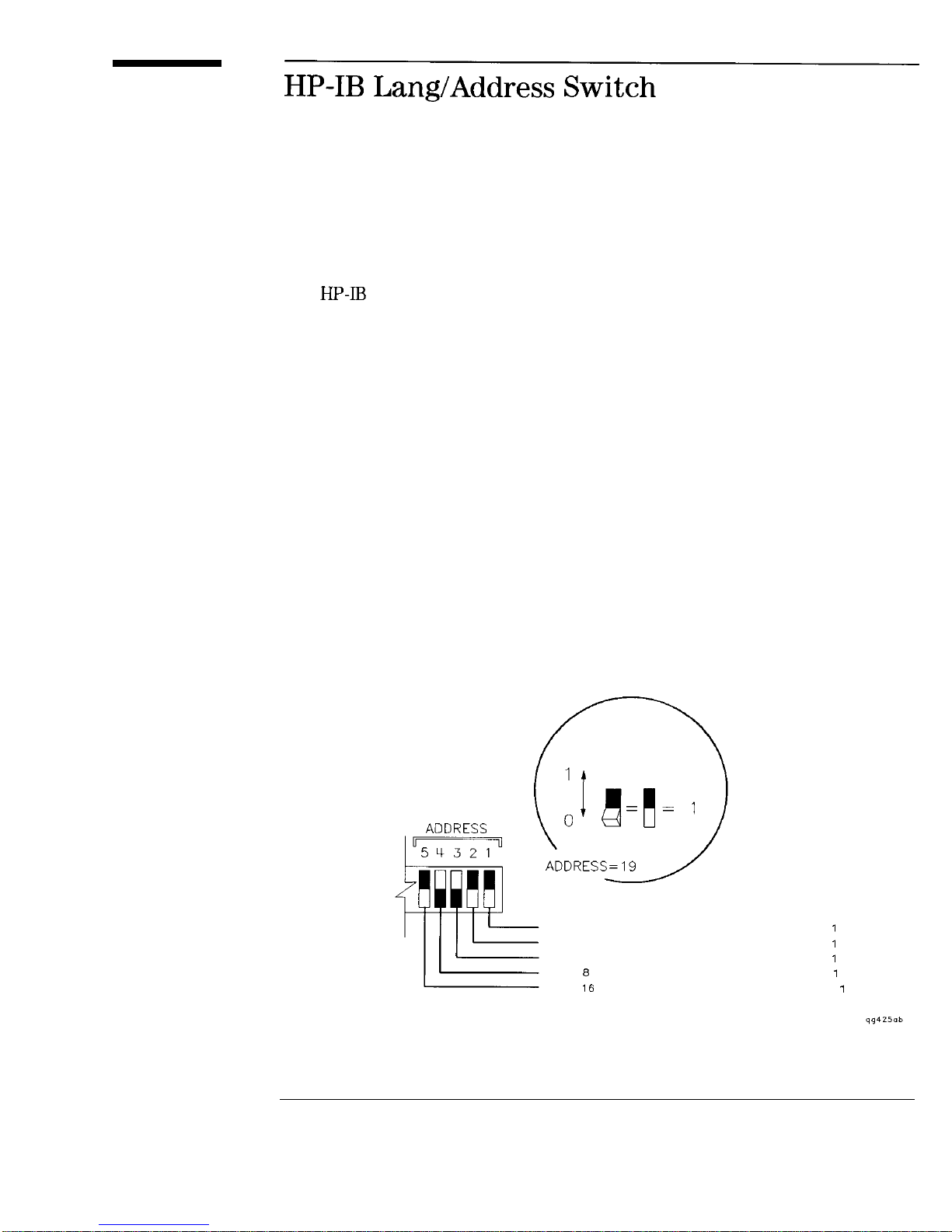
The HP-IR switch on the rear panel is used to select the sweeper language
and
selected via front panel operation.
Refer to Figure 7-8 for a pictorial explanation of the various switch settings
for the HP-IB address of the sweeper. The selected address depicted in this
figure represents an HP-IR address of 19.
When the HP-IR portion of the switch (switch positions 1 through 5) are all
set to 1, any address changes made from the front panel are retained through
a power cycle of the instrument. If you want your sweeper to default to a
particular address at power up, set the switch to the desired. address; you can
still make changes from the front panel, but they won’t be retained through a
power cycle.
address when you apply AC power. These parameters can also be
Refer to Figure 7-9 for a pictorial explanation of the switch settings for
instrument language.
Refer to Figure 7-10 for a pictorial explanation of how to set the switch for
clearing the register contents at power on.
SELECTED
POSITION
ADDS 1 TO ADDRESS IF SELECTED POSITION =
ADDS 2 TO ADDRESS IF SELECTED POSITION =
ADDS 4 TO ADDRESS IF SELECTED POSITION =
ADDS 8 TO ADDRESS IF SELECTED POSITION =
ADDS 16 TO ADDRESS IF SELECTED POSITION =
Figure 7-8. HP-IB Address Switch Settings
7-23
Page 93

Front/Rear Panel
Lang/Address Switch
= SCPI
1
1
0
Figure 7-9. Instrument language Switch Settings
7-24
Register Contents Are
Through An AC Power Cycle.
1
1
0
Register Contents Are Cleared
Through An AC Power Cycle.
Figure
0. Clear Register Contents Settings
Page 94

Front/Rear Panel
HP-IB Lang/Address Switch
“Instrument
For information on setting the
State Keys” panel of the sweeper.
Special
Functions”
For information on setting the language from the front panel
of the sweeper.
address from the front
7-25
Page 95

The front panel knob is used to increase or decrease parameter values.
Pointers (
over a parameter or numeric value in the display indicate
that the function is active and its value will be increased or decreased when
knob is rotated.
The front panel knob is used to give an analog feel to the setting of the
values. Any of the values that can be set through the numeric entry pad, or
the step keys, can also be set using the knob. However, the rate at which the
active parameter varies, for a given amount of knob rotation, is dependent on
the parameter that is being controlled.
If ENTRY OFF
Z/S/ENTER
has been enabled, the pointers will
disappear from the display and rotating the knob will have no affect on the
sweeper parameters until another function key is pressed.
The equivalent SCPI commands for knob rotation are SYST : KEY 6 1 which
simulates clockwise knob rotation, and SYST:KEY 62 which simulates
counterclockwise knob rotation.
7-26
Page 96

INSTRUMENT STATE
SHIFT
PRESET MODE
II
I--
II I
STANDBY LINE POWER SWITCH
Figure
1. The Sweeper line POWER Switch
The line POWER switch turns power to the sweeper to either on or standby.
The sweeper line POWER switch is located at the bottom left corner of the
front panel. Pressing the switch so that the button locks in the “in” position
turns the sweeper on and pressing the switch again so that it is in the “out”
position turns it to standby. When set to standby, most of the sweeper
circuitry is powered off, however, power to the internal timebase (Option
When the sweeper is on, the green LED indicator will be illuminated. When
the sweeper is in standby, the amber LED indicator will be illuminated.
7-27
Page 97

Front/Rear Panel
line POWER Switch
WARNING
Before turning the sweeper on, make sure that it is grounded through
the protective conductor of the power cable to a mains power receptacle
provided with protective earth contact. Any interruption of the
protective grounding conductor inside or outside of the sweeper or
disconnection of the protective earth terminal can result in personal
injury.
7-28
Page 98

The line power cable is supplied in one of several configurations, depending
on the destination of the original shipment.
Each instrument is equipped with a three-wire power cable. When connected
to an appropriate AC power receptacle, this cable grounds the instrument
chassis. The type of power cable shipped with each instrument depends on
the country of destination. See Figure 7-12, “Power Cable and Line (Mains)
Plug Part Numbers”, for the part numbers of these power cables. Cables
are available in different lengths and some with right-angle plugs to the
instrument. Check with your nearest Hewlett-Packard service center for
descriptions and part numbers for these cables.
NOTE
There is no line voltage selector switch on the instrument. The line module will automatically switch
between 110 and 220 Vat as needed.
7-29
Page 99

PLUG TYPE * *
NUMBER
PLUG
DESCRIPTION LENGTH COLOR
CABLE
CABLE
FOR USE
IN COUNTRY
8120-1703 90’
Straight*
8 120-0696
Straight*
90’
8120-1348 Straight*
8120-1378
8120-4753 Straight
8120-4754 90’
8120-5181
Straight”
Straight*
229 (90) Mint Gray
229 (90) Mint Gray Cyprus, Nigeria
201 (79)
221 (87)
201 (79)
201 (79) Mint Gray
203 (80) Block
203
203 (80)
230 (90)
203 (80)
230 (90)
200 (78)
200 (78)
Gray
Gray
Mint Gray
Black
Jade Gray
Gray
Jade
Jade Gray
Great Britain.
Singapore,
Zimbabwe
Argentina,
Australia.
New Zealand,
Mainland China
East and West
African Republic
United Arab
Republic
many nat
United States
Canada,
Japan (100
Colombia,
Philippines,
Taiwan
Israel
in
or
Part number for plug
HP Part Number for complete cable.
E = Earth Ground; L = Line; N = Neutral.
industry identifier for plug only. Number shown for cable
Figure 7-12. Power Cable and line (Mains) Plug Part Numbers
7-30
plug.
Page 100

Instrument State Keys
 Loading...