

Page 1

HP 8360 L-Series Swept CW Generator
(Including Options 001, 004, and 008)
User’s Guide
SERIAL NUMBERS
This manual applies directly to any swept CW generator with the
model and serial number prefix combination shown below. You
may have to modify this manual so that it applies directly to your
instrument version. Refer to the “Instrument History” chapter.
HP
83623L/3OL/4OL/5OL
3844A and below
Pii
HEWLETT
PACKARD
HP Part No. 08380-90134
Printed in USA
February 1999 Supersedes: September 1997
Page 2

Notice
Restricted Rights
Legend
The information contained in this document is subject to change
without notice.
Hewlett-Packard makes no warranty of any kind with regard to this
material, including but not limited to, the implied warranties of
merchantability and fitness for a particular purpose. Hewlett-Packard
shall not be liable for errors contained herein or for incidental
or consequential damages in connection with the furnishing,
performance, or use of this material.
Use, duplication, or disclosure by the U.S. Government is subject
to restrictions as set forth in subparagraph (c) (1) (ii) of the
Rights of Technical Data and Computer Software clause at DFARS
252.227-7013 for DOD agencies, and subparagraphs (c) (1) and
(c) (2) of the C
ommercial
Computer Software Restricted Rights
clause at FAR 52.227-19 for other agencies.
@
Copyright Hewlett-Packard Company 1996, 1997, 1999
All Rights Reserved. Reproduction, adaptation, or translation
without prior written permission is prohibited, except as allowed
under the copyright laws.
1400 Fountaingrove Parkway, Santa Rosa, CA 95403-1799, USA
Page 3

Certification
Hewlett-Packard Company certifies that this product met its
published specifications at the time of shipment from the factory.
Hewlett-Packard further certifies that its calibration measurements
are traceable to the United States National Institute of Standards
and Technology, to the extent allowed by the Institute’s calibration
facility, and to the calibration facilities of other International
Standards Organization members.
Warranty
This Hewlett-Packard instrument product is warranted against
defects in material and workmanship for a period of one year from
date of shipment. During the warranty period, Hewlett-Packard
Company will, at its option, either repair or replace products which
prove to be defective.
For warranty service or repair, this product must be returned to a
service facility designated by Hewlett-Packard. Buyer shall prepay
shipping charges to Hewlett-Packard and Hewlett-Packard shall pay
shipping charges to return the product to Buyer. However, Buyer
shall pay all shipping charges, duties, and taxes for products returned
to Hewlett-Packard from another country.
Hewlett-Packard warrants that its software and firmware designated
by Hewlett-Packard for use with an instrument will execute
its programming instructions when properly installed on that
instrument. Hewlett-Packard does not warrant that the operation
of the instrument, or software, or firmware will be uninterrupted or
error-free.
LIMITATION OF WARRANTY
The foregoing warranty shall not apply to defects resulting from
improper or inadequate maintenance by Buyer, Buyer-supplied
software or interfacing, unauthorized modification or misuse,
operation outside of the environmental specifications for the
product, or improper site preparation or maintenance.
NO OTHER WARRANTY IS EXPRESSED OR IMPLIED.
HEWLETT-PACKARD SPECIFICALLY DISCLAIMS THE
IMPLIED WARRANTIES OF MERCHANTABILITY AND
FITNESS FOR A PARTICULAR PURPOSE.
EXCLUSIVE REMEDIES
THE REMEDIES PROVIDED HEREIN ARE BUYER’S SOLE
AND EXCLUSIVE REMEDIES. HEWLETT-PACKARD SHALL
NOT BE LIABLE FOR ANY DIRECT, INDIRECT, SPECIAL,
INCIDENTAL, OR CONSEQUENTIAL DAMAGES, WHETHER
BASED ON CONTRACT, TORT, OR ANY OTHER LEGAL
THEORY.
. . .
III
Page 4

Assistance
Product maintenance agreements and other customer assistance
agreements are available for Hewlett-Packard products. For any
assistance, contact your nearest Hewlett-Packard Sales and Service
Ofice.
Safety Notes
The following safety notes are used throughout this manual.
Familiarize yourself with each of the notes and its meaning before
operating this instrument.
WARNING
Warning denotes a hazard. It calls attention to a procedure which, if
not correctly performed or adhered to, could result in injury or loss
of life. Do not proceed beyond a warning note until the indicated
conditions are fully understood and met.
CAUTION
Caution denotes a hazard. It calls attention to a procedure that, if
not correctly performed or adhered to, would result in damage to or
destruction of the instrument. Do not proceed beyond a caution sign
until the indicated conditions are fully understood and met.
iv
Page 5

General Safety
Considerations
WARNING
n
No operator serviceable parts inside. Refer servicing to qualified
personnel. To prevent electrical shock, do not remove covers.
n
For continued protection against fire hazard replace line fuse only
with same type and rating (F 5A/250V). The use of other fuses or
material is prohibited.
w
This is a Safety Class I product (provided with a protective earthing
ground incorporated in the power cord). The mains plug shall only
be inserted in a socket outlet provided with a protective earth
contact. Any interruption of the protective conductor, inside or
outside the instrument, is likely to make the instrument dangerous.
Intentional interruption is prohibited.
n
If this instrument is used in a manner not specified by
Hewlett-Packard Co., the protection provided by the instrument may
be impaired. This product must be used in a normal condition (in
which all means for protection are intact) only.
w
Position the instrument according to the enclosure protection
provided. This instrument does not protect against the ingress of
water. This instrument protects against finger access to hazardous
parts within the enclosure.
V
Page 6

CAUTION
n Before switching on this instrument, make sure that the line
voltage selector switch is set to the voltage of the power supply and
the correct fuse is installed.
n Always use the three-prong ac power cord supplied with this
instrument. Failure to ensure adequate earth grounding by not
using this cord may cause instrument damage.
n Before switching on this product, make sure that the line voltage
selector switch is set to the voltage of the power supply and
the correct fuse is installed. Assure the supply voltage is in the
specified range.
n Ventilation Requirements: When installing the instrument in a
cabinet, the convection into and out of the instrument must not be
restricted. The ambient temperature (outside the cabinet) must be
less than the maximum operating temperature of the instrument
by 4 “C for every 100 watts dissipated in the cabinet. If the total
power dissipated in the cabinet is greater than 800 watts, then
forced convection must be used.
n This product is designed for use in Installation Category II and
Pollution Degree 2 per IEC 1010 and 664, respectively.
Note
The detachable power cord is the instrument disconnecting device.
It disconnects the mains circuits from the mains supply before other
parts of the instrument. The front panel switch is only a standby
switch and is not a LINE switch.
vi
Page 7
PREFACE
This manual provides user information for the HP 8360 L-Series
Swept CW Generator.
Instruments Covered
This manual applies to instruments having a serial number prefix
By This Manual
listed on the title page (behind the “Documentation Map” tab).
Some changes may have to be made to this manual so that it
applies directly to each instrument; refer to Chapter 5, “Instrument
History”, to see what changes may apply to your instrument.
A serial number label (Figure O-l) is attached to the instrument’s
rear panel. A prefix (four digits followed by a letter), and a suffix
(five digits unique to each instrument), comprise the instrument
serial number.
SERIAL NUMBER
h
I \
PREFIX
SUFFIX
-A
SER
1234A 12345
\I
INSTALLED
OPTIONS
!
Figure O-l. Typical Serial Number Label
User’s Guide
Tabs divide the major chapters of this manual. The contents of each
Organization
chapter is listed in the Table of Contents.
HP 8360 L-Series
Documentation
Documentation Map
For a pictorial representation of the HP 8360 L-Series documentation,
see the ‘Documentation Map” at the front of this manual.
Ordering Manuals
A manual part number is listed on the title page of this manual.
You may use it to order extra copies of this manual. See
“Replaceable Parts” in HP 8360 B-Series Swept Signal Generator/
HP 8360 L-Series Swept CW Generator Service Guide for a complete
list of HP 8360 documentation and ordering numbers.
vii
Page 8

Typeface
Conventions
The following conventions are used in the HP 8360 L-Series
documentation:
Italics Italic type is used for emphasis, and for titles of manuals and
other publications.
Computer Computer type is used for information displayed on the
instrument. For example: In this sequence, POWER LEVEL is displayed.
(Hardkeys)
Instrument keys are represented in “key cap.” You are
instructed to press a
hardkey.
Softkeys
Softkeys are located just below the display, and their
functions depend on the current display. These keys are represented
in “softkey.” You are instructed to select a softkey.
Regulatory
Information
This product has been designed and tested in accordance with IEC
Publication 1010, Safety Requirements for Electronic Measuring
Apparatus, and has been supplied in a safe condition. The
instruction documentation contains information and warnings
which must be followed by the user to ensure safe operation and to
maintain the instrument in a safe condition.
. . .
VIII
Page 9

Manufacturer’s
Declaration
Note
This is to certify that this product meets the radio frequency
interference requirements of Directive FTZ 1046/1984. The German
Bundespost has been notified that this equipment was put into
circulation and has been granted the right to check the product type
for compliance with these requirements.
Note: If test and measurement equipment is operated with
unshielded cables and/or used for measurements on open set-ups, the
user must insure that under these operating conditions, the radio
frequency interference limits are met at the border of his premises.
Model HP 8360 L-Series Swept CW Generator
Note
Hiermit wird bescheinigt, dass dieses
Gerat/System
in
fibereinstimmung
mit den Bestimmungen von
Postverfiigung
1046/84
funkentst”rt
ist.
Der Deutschen Bundespost wurde das Inverkehrbringen dieses
Gerates/Systems
angezeight und die Berechtigung
zur Uberpriifung
der Serie auf Einhaltung der Bestimmungen
eingeraumt.
Zustzinformation fiir Mess-und Testgerate:
Werden Mess- und Testgerate mit ungeschirmten Kabeln
und/oder
in offenen Messaufbauten verwendet, so ist vom Betreiber
sicherzustellen, dass die Funk-Entst”rbestimmungen unter
Betriebsbedingungen an seiner Grundstiicksgrenze eingehalten
werden.
ix
Page 10
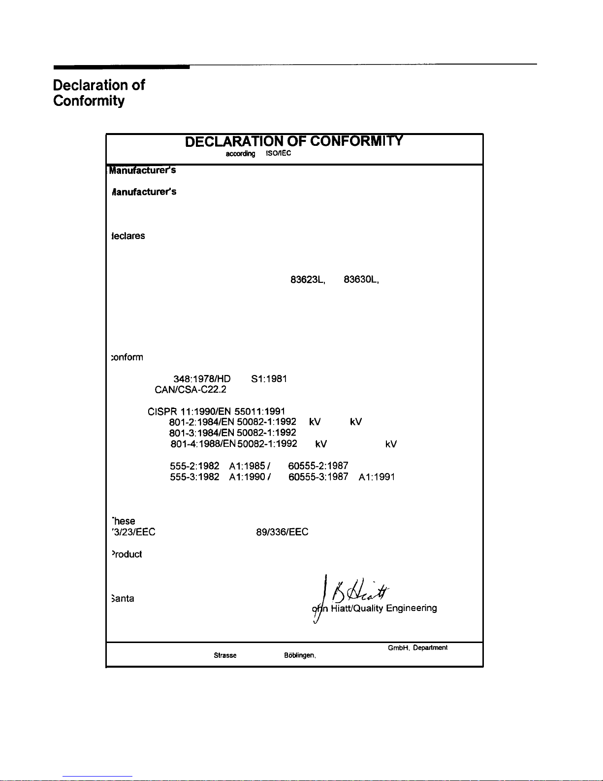
Declaration of
Conformity
DECLARATION OF CONFORMITY
aomrding
to
lSO/lEC
Guide 22 and EN 45014
hanufacturetis
Name:
Hewlett-Packard Co.
lanufactureh
Address:
declares
that the products
Microwave Instruments
Division
1400 Fountaingrove Parkway
Santa Rosa, CA 95403-1799
USA
Product Name:
Synthesized Sweeper
Model Numbers:
HP 83623L, HP
8363OL,
HP 836401.
HP 83650L
Product Options:
This declaration covers all options of the
above products.
:onform
to the following Product specifications:
Safety: IEC
348:1978/HD
401
S1:1981
CAN/CSA-C22.2 No. 231 (Series M-89)
EMC:
CISPR 11:1990/EN 55011:1991
Group I, Class A
IEC
801-2:1984/EN
50082-1:1992
4 kV
CD, 8
kV
AD
IEC
801-3:1984/EN
50082-1:1992
3
V/m, 27-500
MHz
IEC
801-4:1988/EN
50082-I:1992 0.5 kV Sig. Lines, 1 kV Power Lines
IEC
555-2:1982
+
Al:1985 I
EN
60555-2:1987
IEC
555-3:1982
+
Al:1990 /
EN
60555-3:1987
+ Al:1991
Supplementary Information:
-hese
products herewith comply with the requirements of the Low Voltage Directive
‘3/23/EEC and the EMC Directive 89/336/EEC and carry the CE-marking accordingly.
Voduct safety qualification testing for these products was performed prior to 1
December 1993.
Santa
Rosa, California, USA
19 Dec. 1996
J
Manager
European Contact: Your local Hewlett-Packard Sales and Service Office or Hewlett-Packard
GmbH.
Deparlment HQ-TRE.
Herrenbarger
Slrasse
130, D-71 034 BBblingen. Germany (FAX +497031-l 4-3143)
X
Page 11

Compliance with
This is to declare that this instrument is in conformance with the
German Noise
Requirements
German Regulation on Noise Declaration for Machines (Laermangabe
nach
der Maschinenlaermrerordnung -3.GSGV Deutschland).
I
Acoustic Noise Emmission/Geraeuschemission
I
LpA <70 dB
Operator position
Normal position
per IS) 7779
LpA <70 dB
am Arbeitsplatz
normaler Betrieb
nach
DIN 45635 t.19
Instrument Markings !
A
CC
“ISMl-A”
I
I
0
I
N
The instruction documentation symbol. The product is
marked with this symbol when it is necessary for the
user to refer to the instructions in the documentation.
The CE mark is a registered trademark of the European
Community.
The CSA mark is a registered trademark of the
Canadian Standards Association.
This is a symbol of an Industrial Scientific and Medical
Group 1 Class A product.
This is an ON symbol. The symbol ON is used to mark
the position of the instrument power line switch.
This is an ON symbol. The symbol ON is used to mark
the position of the instrument power line switch.
This is a STANDBY symbol. The STANDBY symbol is
used to mark the position of the instrument power line
switch.
This is an OFF symbol. The OFF symbol is used to
mark the position of the instrument power line switch.
This is an AC symbol. The AC symbol is used to
indicate the required nature of the line module input
power.
xi
Page 12
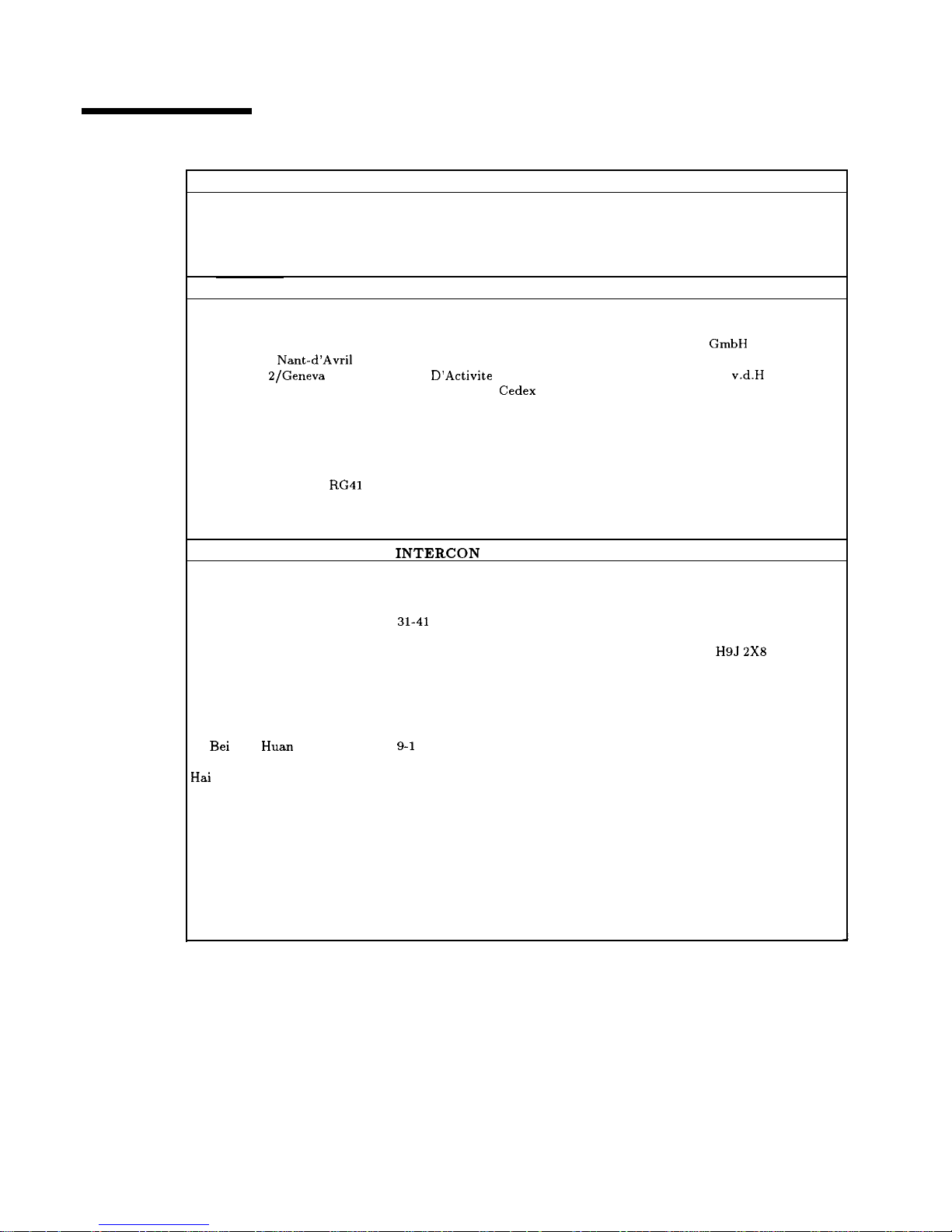
Table O-l. Hewlett-Packard Sales and Service Offices
UNITED STATES
Instrument Support Center
Hewlett-Packard Company
(800) 403-0801
EUROPEAN FIELD OPERATIONS
Headquarters
France
Hewlett-Packard S.A. Hewlett-Packard France
150, Route du Nant-d’Avri1
1 Avenue Du Canada
1217 Meyrin a/Geneva
Zone
D’Activite
De Courtaboeuf
Switzerland
F-91947 Les Ulis
Cedex
(41 22) 780.8111
France
(33 1) 69 82 60 60
Great Britain
Hewlett-Packard Ltd.
Eskdale Road, Winnersh Triangle
Wokingham, Berkshire RG41 5DZ
England
(44 734) 696622
Germany
Hewlett-Packard GmbH
Hewlett-Packard Strasse
61352 Bad Homburg v.d.H
Germany
(49 6172) 16-O
INTERCON
FIELD OPERATIONS
Headquarters
Hewlett-Packard Company
3495 Deer Creek Road
Palo Alto, California, USA
94304-1316
(415) 857-5027
China
China Hewlett-Packard Company
38
Bei
San
Huan
Xl Road
Shuang Yu Shu
Hai
Dian District
Beijing, China
(86 1) 2566888
Taiwan
Hewlett-Packard Taiwan
8th Floor, H-P Building
337 Fu Hsing North Road
Taipei, Taiwan
(886 2) 712-0404
Australia
Hewlett-Packard Australia Ltd.
31-41 Joseph Street
Blackburn, Victoria 3130
(61 3) 895-2895
Japan
Hewlett-Packard Japan, Ltd
9-1
Takakura-Cho, Hachioji
Tokyo 192, Japan
(81 426) 60-2111
Canada
Hewlett-Packard (Canada) Ltd.
17500 South Service Road
Trans-Canada Highway
Kirkland, Quebec
H9J
2X8
Canada
(514) 697-4232
Singapore
Hewlett-Packard Singapore (Pte.) Ltd.
150 Beach Road
#29-00 Gateway West
Singapore 0718
(65) 291-9088
xii
Page 13

Contents
Contents-l
1. Getting Started
What Is In This Chapter
............
How To Use This Chapter
............
Equipment Used In Examples
.........
Introducing the HP 8360 L-Series Swept CW
Generators
.................
Display Area
..................
Entry Area
..................
CW Operation and Start/Stop Frequency Sweep . .
CW Operation
................
Start/Stop Frequency Sweep
..........
Center Frequency/Span Operation
........
Power Level and Sweep Time Operation
......
Power Level Operation
............
Sweep Time Operation
............
Continuous, Single, and Manual Sweep Operation
.
Marker Operation
...............
Saving and Recalling an Instrument State
.....
Power Sweep and Power Slope Operation
.....
Power Sweep Operation
............
Power Slope Operation
............
Getting Started Advanced
............
Externally Leveling the Swept CW Generator ...
Leveling with Detectors/Couplers /Splitters ...
External Leveling Used With the Optional Step
Attenuator
...............
Leveling with Power Meters
..........
Leveling with MM-wave Source Modules
.....
Working with Mixers/Reverse Power Effects ....
Working with Spectrum Analyzers/Reverse Power
Effects
...................
Optimizing Swept CW Generator Performance ...
Creating and Applying the User Flatness Correction
Array
..................
Creating a User Flatness Array Automatically,
Example 1
...............
Creating a User Flatness Array, Example 2
. .
Swept mm-wave Measurement with Arbitrary
Correction Frequencies, Example 3 ....
Scalar Analysis Measurement with User Flatness
Corrections, Example 4
.........
Using Detector Calibration
..........
l-l
l-2
l-2
1-3
l-4
1-5
1-6
l-6
l-6
l-8
l-10
l-10
l-10
l-12
1-14
1-16
1-18
1-18
1-19
l-21
l-23
l-23
l-26
l-27
l-28
l-30
l-32
l-33
l-33
l-34
1-36
1-39
l-43
l-47
Page 14

Using the Tracking Feature ..........
Peaking ..................
Tracking .................
ALC Bandwidth Selection ............
Using Step Sweep ...............
Creating and Using a Frequency List .......
Using the Security Features ...........
Changing the Preset Parameters .........
Getting Started Programming ..........
HP-IB General Information ...........
Interconnecting Cables ............
Instrument Addresses .............
HP-IB Instrument Nomenclature ........
Listener ..................
Talker. ..................
Controller .................
Programming the Swept CW Generator .....
HP-IB Command Statements .........
Abort ...................
Remote ..................
Local Lockout ...............
Local ...................
Clear ...................
output ..................
Enter ...................
Getting Started with SCPI ...........
Definitions of Terms ..............
Standard Notation ..............
Command Mnemonics ...........
Angle Brackets ...............
How to Use Examples .............
Command Examples ............
Response Examples .............
Essentials for Beginners .............
Program and Response Messages .......
Forgiving Listening and Precise Talking ....
Types of Commands ............
Subsystem Command Trees ..........
The Command Tree Structure ........
Paths Through the Command Tree ......
Subsystem Command Tables ..........
Reading the Command Table ........
More About Commands ...........
Query and Event Commands ........
Implied Commands ............
Optional Parameters ...........
Program Message Examples .........
Parameter Types ..............
Numeric Parameters ...........
Extended Numeric Parameters .......
Discrete Parameters ...........
l-49
l-49
1-49
l-50
1-51
l-52
l-53
l-54
l-55
l-56
1-56
1-56
1-56
l-56
l-56
l-56
l-56
l-57
l-57
l-58
l-58
l-59
l-59
l-60
1-61
1-63
l-63
l-64
l-64
l-64
1-64
l-64
l-65
l-66
l-66
l-66
l-67
l-68
l-68
l-68
1-71
1-71
l-72
l-72
l-72
l-72
l-72
l-73
l-73
l-74
l-75
Contents-2
Page 15

Boolean Parameters
...........
Reading Instrument Errors
..........
Example Programs
..............
Example Program
.............
Description
...............
Program Listing
.............
Program Comments
...........
Details of Commands and Responses
.......
In This Subsection
..............
Program Message Syntax
...........
Subsystem Command Syntax
........
Common Command Syntax
.........
Response Message Syntax
...........
SCPI Data Types
..............
Parameter Types
..............
Numeric Parameters
...........
Extended Numeric Parameters
.......
Discrete Parameters
...........
Boolean Parameters
...........
Response Data Types
............
Real Response Data
...........
Integer Response Data
..........
Discrete Response Data
..........
String Response Data
...........
Programming Typical Measurements
.......
In This Subsection
..............
Using the Example Programs
.........
Use of the Command Tables
.........
HP-IB Check, Example Program 1
.......
Program Comments
............
Local Lockout Demonstration, Example Program 2
Program Comments
............
Setting Up A Typical Sweep, Example Program 3
Program Comments
............
Queries, Example Program 4
..........
Program Comments
............
Saving and Recalling States, Example Program 5 .
Program Comments
............
Looping and Synchronization, Example Program 6
Program Comments
............
Using the
*WA1
Command, Example Program 7 .
Program Comments
............
Using the User Flatness Correction Commands,
Example Program 8
............
Programming the Status System
.........
In This Subsection
..............
General Status Register Model
.........
Condition Register
.............
Transition Filter
..............
Event Register
...............
Enable Register
..............
l-75
l-76
1-77
l-77
l-77
l-77
l-78
l-80
l-80
l-80
1-81
1-81
l-82
l-83
l-83
l-83
l-84
l-85
l-85
l-85
l-85
1-86
l-86
l-86
1-87
l-87
l-87
l-88
l-90
l-90
l-91
l-92
l-93
l-93
l-95
l-95
l-97
l-97
l-99
1-99
l-101
l-101
l-103
l-106
l-106
l-106
l-106
l-107
l-107
l-107
Contents-3
Page 16

An Example Sequence ...........
Programming the Trigger System
.........
In This Subsection ..............
Generalized Trigger Model ...........
Overview .................
Details of Trigger States ...........
Inside the Idle State ...........
Inside the Initiate State ..........
Inside Event Detection States .......
Inside the Sequence Operation State ....
Common Trigger Configurations ........
The
INIT
Configuration ...........
The TRIG Configuration ..........
Description of Triggering in the HP 8360 L-Series
Swept CW Generators ...........
Advanced Trigger Configurations .......
Trigger Keyword Definitions ..........
ABORt
..................
IMMediate
................
ODELay
.................
SOURce ..................
Related Documents
...............
The International Institute of Electrical and
Electronics Engineers. ...........
Hewlett-Packard Company ...........
l-107
l-109
l-109
l-109
l-109
l-110
l-111
l-111
1-112
l-114
l-115
1-115
1-116
l-117
1-118
1-118
l-118
1-118
1-118
1-119
l-120
l-120
l-120
2. Operating and Programming Reference
How To Use This Chapter . . . . . . . . . . . .
2-1
A.
Address . . . . . . . . . . . . . . . . . . . .
A-l
Adrs
Menu . . . . . . . . . . . . . . . . . .
A-l
(ALC).
....................
A-3
ALC Bandwidth Select Auto
..........
A-10
ALC Bandwidth Select High
..........
A-10
ALC Bandwidth Select Low
..........
A-11
ALC3WMenu
.................
A-11
Altrnate Regs
................
A-12
Amp1
Markers
.................
A-13
ANALYZER STATUS REGISTER
........
A-13
Arrow Keys
..................
A-16
[ASSIGN).
....................
A-17
Auto Fill
Incr
................
A-18
Auto Fill #Pts
................
A-19
Auto Fill Start
...............
A-20
Auto Fill Stop
................
A-21
Auto Track
..................
A-22
Contents-4
Page 17

B.
BLankDisp
. . . . . . . . . . . . . . . . . .
B-l
C.
(CENTER)
.....................
C-l
Center=Marker
................
c-2
Clear Fault
.................
c-2
Clear Memory
.................
c-3
Clear Point
.................
c-4
CONNECTORS ................
c-4
(CONT)
.....................
c-10
CopyList
..................
c-11
CorPair
Disable
...............
c-11
Coupling Factor
...............
c-12
(cw
.....................
c-12
CW/CF
Coupled
................
c-13
D.
Dblr Amp Menu
................
D-l
Delete Menu
.................
D-2
Delete All
..................
D-2
Delete Current
................
D-3
Delete Undef
.................
D-3
DeltaMarker
.................
D-4
Delta Mkr Ref
................
D-5
Disp Status
.................
D-5
Doubler Amp Wode AUTO
............
D-7
Doubler
Amp
Mode Off
............
D-7
Doubler
Arap
Mode On
.............
D-8
Dwell Coupled
................
D-9
E.
8360Adrs
..................
EnterCorr
..................
EnterFreq..
................
Enter List Dwell
..............
Enter List Freq
...............
Enter List Offset
..............
ENTRY KEYS .................
ENTRY ON/OFF)
.................
ExtDet Cal
.................
E-l
E-l
E-2
E-2
E-3
E-4
E-4
E-5
E-5
Contents-5
Page 18
F.
Fault Menu
..................
F-l
Fault Info 1
.................
F-2
Fault Info 2
.................
F-3
Fault Info 3
.................
F-4
Fltness Menu
.................
F-5
(FLTNEss ON/OF)
................ F-10
Freq Cal Menu
................
F-11
Freq Follow .................
F-11
FREQUENCY
(e)
...............
F-12
Freq
Mult
.................. F-13
Freq Offset
.................
F-14
FullUsr
Cal
.................
F-14
G.
Global Dwell . . . . . . . . . . . . . . . . .
G-l
Global Offset . . . . . . . . . . . . . . . .
G-l
H.
HP-IB Address . . . . . . . . . . . . . . . . . H-l
HP-IB Menu . . . . . . . . . . . . . . . . . .
H-l
L.
Leveling
ModeALCof f
............. L-l
Leveling
ModeNorxtal
.............
L-2
Leveling
ModeSearch
.............
L-2
Leveling
PointExtDet
............
L-3
Leveling PointIntml
............
L-3
Leveling
PointModule
............
L-4
Leveling
PointPwrMtr
............
L-5
LINE SWITCH
................
L-5
ListMenu
..................
L-6
List
Mode
Pt
TrigAuto
............
L-8
List Mode Pt
TrigBus
............
L-9
List Mode Pt
TrigExt
............
L-9
(TEL-)
.....................
L-10
Contents-6
Page 19
MI--M2
Sweep . . . .
Manual Sweep . . . .
(MARKER) . . . . . .
Marker Mi . . . . .
Marker M2 . . . . .
Marker M3 . . . . .
Marker M4 . . . . .
Marker
M5
. . . . .
Markers All Off . .
Measure Corr All .
Measure Corr Current
Measure Corr Undef
Meter Adss . . . . .
INIOD)
. . . . . . . .
Module Menu . . . .
Module Select AUTO
Module Select Front
Module Select None
Module Select Rear
more n/m . . . . . .
Mtr
Meas
Menu . . .
P.
Peak RF Always . . .
. . . . . . . . . . . . .
Pulse
On/OffScal.ar
Pwr Mtr Range . . .
.............
.............
.............
.............
.............
.............
.............
.............
.............
.............
............
.............
.............
.............
.............
.............
.............
.............
.............
.............
.............
.............
.............
. . . . . . . . . . . . .
. . . . . . . . . . . . .
. . . . . . . . . . . . .
. . . . . . . . . . . . .
Analyzr
........
CIIL
..........
SCPI
. . . . . . . . . .
. . . . . . . . . . . . .
. . . . . . . . . . . . .
M-l
M-l
M-3
M-4
M-5
M-5
M-6
M-6
M-7
M-7
M-8
M-8
M-9
M-9
M-10
M-11
M-11
M-12
M-13
M-13
M-14
P-l
P-2
P-2
P-5
P-6
P-7
P-8
P-9
P-10
P-11
P-11
P-12
P-13
P-13
P-14
P-15
P-15
P-16
Contents-7
Page 20
R.
(RECALL)
....................
R-l
Ref Osc Menu
.................
R-l
@Eqz--
..................
R-2
ROTARY KNOB ................
R-2
S.
LSAVE)
.....................
S-l
SaveLock
..................
s-2
Save User Preset
..............
s-2
SCPI Conformance Information
.........
s-3
SCPI COMMAND SUMMARY
SCPI STATUS REGISTER
STRUbitiRi
. : : : :
s-12
S-48
Security Menu
................
s-50
Selftest
(Full)
...............
s-51
SetAtten
..................
s-51
[piEiF)
.....................
S-52
Software Rev
.................
S-52
@KJ
.....................
s-53
(START)
.....................
s-53
Start=Ml Stop=M2
..............
s-54
Start Sweep Trigger Auto
..........
s-55
Start Sweep Trigger Bus
...........
s-55
Start Sweep Trigger Ext
...........
S-56
Step Control Master
.............
S-56
Step Control Slave
.............
S-58
Step Dwell
..................
s-59
Step Points
.................
S-60
StepSize
..................
S-60
Step
Sup
Menu
................
S-61
Step
Sup
PtTrig Auto
............
S-62
Step
Sup
PtTrig Bus
.............
S-62
Step
Sup
PtTrig Ext
.............
S-63
ISTOP)
.....................
S-63
SWEEP
(MENU)
.................
S-64
Sweep Mode List
...............
S-65
Sweep Mode Ramp
...............
S-66
Sweep Mode Step
...............
S-66
Sup
Span
CalAlways
.............
S-67
Sup
Span
CalOnce
..............
S-67
(SWEEP TIME)
..................
S-68
SwpTime
Auto
.................
S-68
SYSTEM
(MENU)
.................
S-69
Contents-8
Page 21
m
1.
10
MHz Freq Std Auto
............
10
MHz Freq Std Extrnl
...........
10 MHz Freq Std Intrnl
...........
10 MHz Freq Std None
............
Tracking Menu
................
TrigOut
Delay
................
U.
Uncoupl Atten
......
Unlock Info
.......
Up/Down Power
......
Up/Dn Size CW
......
Up/Dn Size Swept
....
(USER)
..........
USER DEFINED
(FV1ENU)
. .
VsrKev
Clear
.......
*
UsrMenu Clear . . . . . .
. . . .
. . . .
. . . .
. . . .
. . . .
. . . .
. . . .
. . . .
. . . .
. . . .
. . . .
. . . .
. . . .
. . . .
. . . .
. . . .
. . . .
. . . .
. .
. .
. .
. .
. .
. .
. .
. .
. .
Zero Freq . . . . . . . . . . . . . . . . . .
z-1
Zoom . . . . . . . . . . . . . . . . . . . . .
z-1
2a. Error Messages
Introduction . . . . . . . . . . . . . . . . . .
Front Panel Error Messages in Alphabetical Order
.
SCPI Error Messages in Numerical Order . . . . .
Swept CW Generator Specific SCPI Error Messages
Universal SCPI Error Messages . . . . . . . .
Error Messages From -499 To -400 . . . . .
Error Messages From -399 To -300 . . . . .
Error Messages From -299 To -200 . . . . .
Error Messages From -199 to -100 . . . . . .
2b. Menu Maps
ALC Menu
..................
Frequency Menu
................
Marker Menu
.................
Modulation Menu
...............
Power Menu
..................
Service Menu
.................
Sweep Menu
..................
System Menu
.................
User Cal Menu
.................
T-l
T-l
T-2
T-2
T-3
T-3
U-l
U-l
u-2
u-2
u-3
u-4
u-4
u-5
u-5
2a-1
2a-1
2a-5
2a-5
2a-6
2a-6
2a-6
2a-6
2a-7
2b-3
2b-5
2b-7
2b-9
2b-11
2b-13
2b-15
2b-17
2b-19
Contents-9
Page 22
2c. Specifications
Frequency ...................
Range ....................
Resolution ..................
Frequency Bands (for CW signals)
.......
Frequency Modes: ..............
CW and Manual Sweep
............
Synthesized Step Sweep
............
Synthesized List Mode
............
Ramp Sweep Mode ..............
Internal 10 MHz Time Base
..........
RF Output ..................
Output Power ................
Accuracy ( dB)4
..............
Flatness
(dB)
...............
Analog Power Sweep .............
External Leveling ...............
Source Match ................
Spectral Purity .................
Spurious Signals ...............
Single-Sideband Phase Noise (dBc/Hz)
.....
Offset from Carrier .............
Residual FM (RMS, 50 Hz to 15 kHz bandwidth) .
General ....................
Environmental ................
Warm-Up Time ...............
Power Requirements .............
Weight & Dimensions .............
Adapters Supplied ..............
Inputs & Outputs ..............
Auxiliary Output ..............
RF Output ................
External ALC Input
............
Trigger Input ...............
Trigger Output ...............
10 MHz Reference Input
...........
10 MHz Reference Output
..........
Sweep Output ...............
Stop Sweep Input/Output
..........
Z-Axis Blanking/Markers Output
.......
Volts/GHz Output .............
Source Module Interface
...........
Auxiliary Interface .............
Models ...................
Options ...................
Option 001 Add Step Attenuator
.......
Option 004 Rear Panel RF Output
......
Option 008 1 Hz Frequency Resolution
....
Option 700 MATE System Compatibility
...
Option 806 Rack Slide Kit
..........
Option 908 Rack Flange Kit
.........
2c-2
2c-2
2c-2
2c-2
2c-2
2c-2
2c-3
2c-3
2c-3
2c-3
2c-4
2c-4
2c-5
2c-5
2c-6
2c-6
2c-6
2c-7
2c-7
2c-9
2c-9
2c-9
2c-10
2c-10
2c-10
2c-10
2c-10
2c-10
2c-11
2c-11
2c-11
2c-11
2c-11
2c-11
2c-11
2c-11
2c-11
2c-11
2c-12
2c-12
2c-12
2c-12
2c-12
2c-12
2c-12
2c-12
2c-12
2c-12
2c-13
2c-13
Contents- 10
Page 23

Option 910 Extra Operating & Service Guides .
Option 013 Rack Flange Kit
.........
Option W30 Two Years Additional Return-To-HP
Service
.................
3. Installation
Initial Inspection
................
Equipment Supplied
..............
Options Available
...............
Preparation for Use
...............
Power Requirements
.............
Line Voltage and Fuse Selection
........
Power Cable
.................
Language Selection
..............
How to View or Change a Language Selection from
the Front Panel
.............
How to Select a Language on a Swept CW
Generator without a Front Panel
.....
HP-IB Address Selection
...........
How to View or Change an HP-IB address from
the Front Panel
.............
How to Prevent a Front Panel Change to an HP-IB
Address
................
How to Set the HP-IB Address on a Swept CW
Generator without a Front Panel
.....
Mating Connectors
..............
10 MHz Frequency Reference Selection and Warmup
Time
..................
Operating Environment
............
Chassis Kits
..................
Rack Mount Slide Kit (Option 806)
.......
Installation Procedure
............
Rack Flange Kit for Swept CW Generators with
Handles Removed (Option 908)
.......
Installation Procedure
............
Rack Flange Kit for Swept CW Generators with
Handles Attached (Option 913)
.......
Installation Procedure
............
Storage and Shipment
..............
Environment
.................
Package the Swept CW Generator for Shipment
.
Converting HP 8340/41 Systems to HP 8360 L-Series
Systems
..................
Manual Operation
..............
Compatibility
...............
Front Panel Operation
...........
Instrument Preset Conditions
.......
System Connections
.............
The HP 8510 Network Analyzer
.......
The HP
8757C/E
Scalar Network Analyzer
. .
2c-13
2c-13
2c-13
3-l
3-2
3-2
3-3
3-3
3-3
3-4
3-6
3-6
3-6
3-7
3-8
3-8
3-8
3-8
3-8
3-9
3-10
3-10
3-11
3-13
3-14
3-15
3-16
3-17
3-17
3-18
3-19
3-20
3-20
3-20
3-20
3-21
3-21
3-22
Contents-l 1
Page 24

The HP 83550 Series Millimeter-wave Source
Modules . . . . . . . . . . . . . . .
The HP 8970B Noise Figure Meter . . . . .
Remote Operation . . . . . . . . . . . . .
Language Compatibility . . . . . . . . . .
Network Analyzer Language . . . . . . . .
Test and Measurement System Language . .
Control Interface Intermediate Language . .
Converting from Network Analyzer Language to
SCPI
. . . . . . . . . . . . . . . . .
Numeric Suffixes . . . . . . . . . . . . .
Status Bytes . . . . . . . . . . . . . . .
3-22
3-22
3-23
3-23
3-23
3-23
3-23
3-23
3-24
3-24
4. Operator’s Check and Routine Maintenance
Operator’s Checks
...............
Service Information
..............
Local Operator’s Check
.............
Description
.................
Preliminary Check
..............
Main Check
.................
Routine Maintenance
..............
How to Replace the Line Fuse
.........
How to Clean the Fan Filter
..........
How to Clean the Cabinet
...........
How to Clean the Display Filter
........
4-l
4-l
4-2
4-2
4-2
4-3
4-4
4-4
4-5
4-6
4-6
5. Instrument History
Index
Contents-12
Page 25

Figures
Contents-13
O-l. Typical Serial Number Label
..........
l-l. The HP 8360 L-Series Swept CW Generator
...
l-2. Display
...................
l-3. Entry Area
.................
l-4. CW Operation and Start/Stop Frequency Sweep .
l-5. Center Frequency and Span Operation
.....
l-6. Power Level and Sweep Time Operation
.....
l-7. Continuous, Single, and Manual Sweep Operation
l-8. Marker Operation
..............
l-9. Saving and Recalling an Instrument State
....
l-10. Power Sweep and Power Slope Operation
....
l-11. ALC Circuit Externally Leveled
........
1-12. Typical Diode Detector Response at 25°C
....
1-13. Leveling with a Power Meter
..........
1-14. MM-wave Source Module Leveling
.......
1-15. MM-wave Source Module Leveling Using a Microwave
Amplifier
.................
1-16. Reverse Power Effects, Coupled Operation with
-8dBm Output
..............
1-17. Reverse Power Effects, Uncoupled Operation with
-8dBm Output
..............
1-18. Creating a User Flatness Array Automatically . .
1-19. Creating a User Flatness Array
.........
l-20. Creating Arbitrarily Spaced Frequency-Correction
Pairs in a Swept mm-wave Environment ...
1-21. Scalar System Configuration
..........
l-22. Automatically Characterizing and Compensating for
a Detector
................
l-23. Decision Tree for ALC Bandwidth Selection
...
l-24. SCPI Command Types
............
l-25. A Simplified Command Tree
..........
l-26. Proper Use of the Colon and Semicolon
.....
l-27. Simplified
SWEep
Command Tree
.......
l-28. Voltage Controlled Oscillator Test
.......
l-29. Simplified Program Message Syntax
.......
l-30. Simplified Subsystem Command Syntax
.....
1-31. Simplified Common Command Syntax
.....
l-32. Simplified Response Message Syntax
......
l-33. Generalized Status Register Model
.......
l-34. Typical Status Register Bit Changes
......
l-35. Generalized Trigger Model
...........
l-36. Inside the Idle State
.............
vii
l-3
1-4
1-5
1-7
1-9
l-11
l-13
1-15
1-17
1-19
l-23
l-25
l-27
l-28
l-29
1-31
1-31
l-34
l-37
l-40
l-43
1-47
l-50
l-67
l-68
l-70
1-71
l-77
l-80
1-81
l-82
1-82
l-106
l-108
l-110
l-111
Page 26
l-37. Inside the Initiate State . . . . . . . . . . . .
l-38. Inside an Event Detection State . . . . . . . .
l-39.
Inside the Sequence Operation State . . . . . .
l-40.
The
INIT
Trigger Configuration . . . . . . . .
1-41.
The TRIG Trigger Configuration . . . . . . . .
l-42. HP 8360 Simplified Trigger Model . . . . . . .
A-l.
ALC System Simplified Block Diagram . . . . .
A-2.
Typical External Leveling Hookup . . . . . . .
C-l. Auxiliary Interface Connector . . . . . . . . .
c-2.
HP-IB Connector and Cable . . . . . . . . . .
c-3. Interface Signals of the Source Module Connector .
F-l.
Basic User Flatness Configuration Using an HP 437B
F-2.
F-3.
F-4.
Power Meter . . . . . . . . . . . . . . .
User Flatness Correction Table as Displayed by the
Swept CW Generator . . . . . . . . . . .
The Sources of ALC Calibration Correction Data .
Array Configuration when the Correction Data
Frequency Span is a Subset of the Swept CW
Generator Frequency Span . . . . . . . . .
P-l.
S-l.
How(PRIOR)Works . I
.-.
. . . . . . . . . .
Connections Required for a Two-Tone Scalar
2b-1.
2b-2.
2b-3.
2b-4.
2b-5.
2b-6.
2b-7.
2b-8.
2b-9.
3-l.
3-2.
3-3.
3-4.
3-5.
3-6.
4-l.
Network Analyzer Measurement System
...
ALC Menu
.................
Frequency Menu
.............
.,
.
Marker Menu
................
Modulation Menu
..............
Power Menu
.................
Service Menu
................
Sweep Menu
.................
System Menu
................
User Cal Menu
................
AC Power Cables Available
..........
Rear Panel HP-IB Switch
...........
Removing the Side Straps and Feet
.......
Chassis Slide Kit
...............
Rack Mount Flanges for Swept CW Generators with
Handles Removed
.............
Rack Mount Flanges for Swept CW Generators with
Handles Attached
.............
Replacing the Line Fuse
............
4-2. Removing the Fan Filter . . . . . . . . . . .
l-111
1-113
1-114
l-115
l-116
1-117
A-5
A-8
C-6
c-7
c-9
F-6
F-7
F-8
F-8
P-12
s-57
2b-3
2b-5
2b-7
2b-9
2b-11
2b-13
2b-15
2b-17
2b-19
3-5
3-7
3-11
3-12
3-14
3-16
4-4
4-5
Contents-14
Page 27

Tables
l-l. Keys Under Discussion in This Section
.....
l-2.
SWEep
Command Table
...........
l-3. SCPI Data Types
..............
l-4. Sample Swept CW Generator Commands
....
C-l. Pin Description of the Auxiliary Interface
....
D-l. Mnemonics used to Indicate Status
.......
S-l. HP 8360 SCPI COMMAND SUMMARY
....
3-l. Adapter Descriptions and Part Numbers Shipped
with Each Swept CW Generator Model
...
3-2. Language HP-IB Addresses
..........
3-3. Factory-Set HP-IB Addresses
.........
3-4. Rack Mount Slide Kit Contents
........
3-5. Rack Flange Kit for Swept CW Generators with
Handles Removed Contents
.........
3-6. Rack Flange Kit for Swept CW Generators with
Handles Attached Contents
.........
3-7. Instrument Preset Conditions for the HP
8360/8340/8341
..............
3-8. Numeric Suffixes ...............
3-9. Programming Language Comparison
......
4-l. Fuse Part Numbers
..............
1-21
1-71
l-83
l-88
C-6
D-6
S-16
3-2
3-6
3-7
3-10
3-13
3-15
3-20
3-24
3-25
4-4
Contents-15
Page 28

1
Getting Started
What Is In This
Chapter
This chapter contains information on how to use the
HP 8360 L-Series Swept CW Generator. The information is
separated into three sections.
Basic For the novice user unfamiliar with the
HP 8360 L-Series Swept CW Generator. This
section describes the basic features of the swept CW
generator.
Note
Advanced
Programming
For the user familiar with swept CW generators,
but not necessarily familiar with how to use the
special features of the HP 8360 L-Series Swept CW
Generator.
For the user wishing to program an HP 8360 L-Series
Swept CW Generator. This section contains
an introduction to Standard Commands
for Programmable Instruments language
(SCPI), Hewlett-Packard’s implementation of
IEEE-488.2-1987, and an introduction to the
Analyzer programming language.
If you are unpacking a new swept CW generator, refer to the
installation suggestions provided in Chapter 3, “Installation”.
Getting Started Introduction
l-1
Page 29

How To Use This
Chapter
To use this chapter effectively, refer to the tabbed section “Menu
Maps”. Menu maps can be folded out to be viewed at the same time
as the Getting Started information, as illustrated.
tl-
I
1
Equipment Used In
The following table lists the equipment used in the operation
Examples
examples shown in this chapter. You can substitute equipment, but
be aware that you may get different results than those shown.
Equipment Used In Examples
Equipment
Recommended
Model Numbers
I
Power Meter
HP
436A/437B
I
Power Sensor
I
HP 8485A
I
Oscilloscope
mm-Wave Source Module HP 83556A
I
Power Amplifier
HP 8349B
1
Detector
t
HP 8474D
1-2 Getting Started Introduction
Page 30
Getting Started Basic
Introducing the
HP 8360 L-Series
Swept CW
Generators
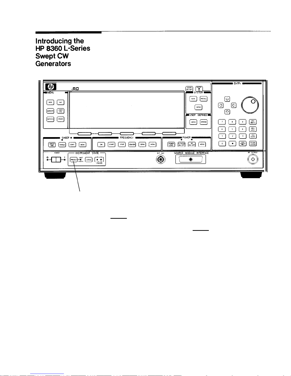
The HP 8360 L-Series Swept CW Generators are high performance,
broadband frequency swept CW generators.
HEWLETT
PACKP
rR0
.MENU
SELECT
,,-ENTRY-
IzEJm
J
SYSTEM
[YM]
@
u
cEil
%I@
USER
DrnNED
u
@1Lalc*l
pJ(TJm@J
rmrm
PRESET
Figure l-l. The HP 8360 L-Series Swept CW Generator
(PRESET) initializes the front panel settings and runs the swept CW
generator through a brief self-test. In the following examples, unless
stated otherwise, begin by pressing (PRESET).
Getting Started Basic l-3
Page 31

Display Area
\
SOFTKEYS
ACTIVE ENTRY AND
DATA DISPLAY AREA
J
-
MESSAGE LINE
1
SOFTKEY
LABEL AREA
Figure l-2. Display
Active Entry and Data Display Area: This area typically displays
the frequency and power information of the current instrument
state. When data entry is expected, the swept CW generator uses
all or part of this area to record the entries. The active entry
arrow (
-->)
indicates the active entry function and its current
value.
Message Line: This line is used to display:
ALC level status.
Unlock information.
Timebase
status.
RF output status.
Softkey
Label Area: This area displays the name of the softkey
directly below it.
Softkeys: These keys activate the functions indicated by the labels
directly above them.
l-4 Getting Started Basic
Page 32

Entry Area
All function values are changed via the rotary knob and/or keys of
the entry area.
ENTRY
ENTRY ON
ON/OFF
LED
ARROW KEYS
ROTARY KNOB
NUMkIC
NEGAti
SIGN/
ENTRY KEYS
BACKSPACE
Figure l-3. Entry Area
The following are active only when the swept CW generator expects
an input.
(ENTRY ON/OFF): This key lets you turn off or on the active entry
area. Turning off the entry area after a value is entered prevents
accidental changes.
ENTRY ON LED: This LED lights when the entry area is active.
Arrow Keys: The up/down arrow keys let you increase or decrease
a numeric value. The left/right arrow keys choose a significant
digit indicated by an underline.
Rotary Knob: The rotary knob increases or decreases a numeric
value. The rotary knob can be used in combination with the
left/right arrow keys to change the increment size.
Terminator Keys: After the numeric entry keys are used to enter a
value, these keys define the units.
Negative Sign/Backspace Key: If a data entry is in progress, this
key backspaces over the last digit entered, otherwise a negative
sign is entered.
Numeric Entry Keys: These keys enter specific numbers in the
active entry area and must be followed by one of the terminator
keys before the function value changes.
Getting Started Basic
l-5
Page 33
CW Operation and
Start/Stop
Frequency Sweep
CW Operation
CW operation is one of the major functions of the swept CW
generator, and is easy to do using front panel keys. In CW operation,
the swept CW generator produces a single, low-noise, synthesized
frequency. Try this example: Press
m (i-J @ (J @ @ (?J @ 0 @
@J.
Check the active entry area. It indicates:
-->
cw:
12345.678000 MHz
The data display area indicates CW operation and the frequency
that you entered. The ENTRY ON LED is lit and the green SWEEP
LED is off.
Try other frequencies. Experiment with the rotary knob and the
arrow keys as alternate methods of data entry.
Start/Stop Frequency
The swept CW generator can sweep a frequency span as wide as
Sweep
the frequency range of the instrument, or as narrow as 0 Hz (swept
CW).
In start/stop sweep operation, the swept CW generator produces
a sweep from the selected start frequency to the selected stop
frequency.
For example:
Press
[START) @ (J @ @ [GHz).
Press
ISTOP) 0 0 @ @ LGHz).
The data display area indicates the start frequency and the stop
frequency. The green SWEEP LED is on (periodically off when
sweep is retracing). Because this is the active function, the active
entry area indicates:
-->
STOP
FREqUENCY:
7890.000000 MHz
Any subsequent entries change the stop frequency. To change the
start frequency, press
[START),
which remains the active function until
you press a different function key.
1-6 Getting Started Basic
Page 34

HEWLETT
PACKARD
IMENU
SELECT
FREQUENCY
SWEEP LED
cw
START
STOP
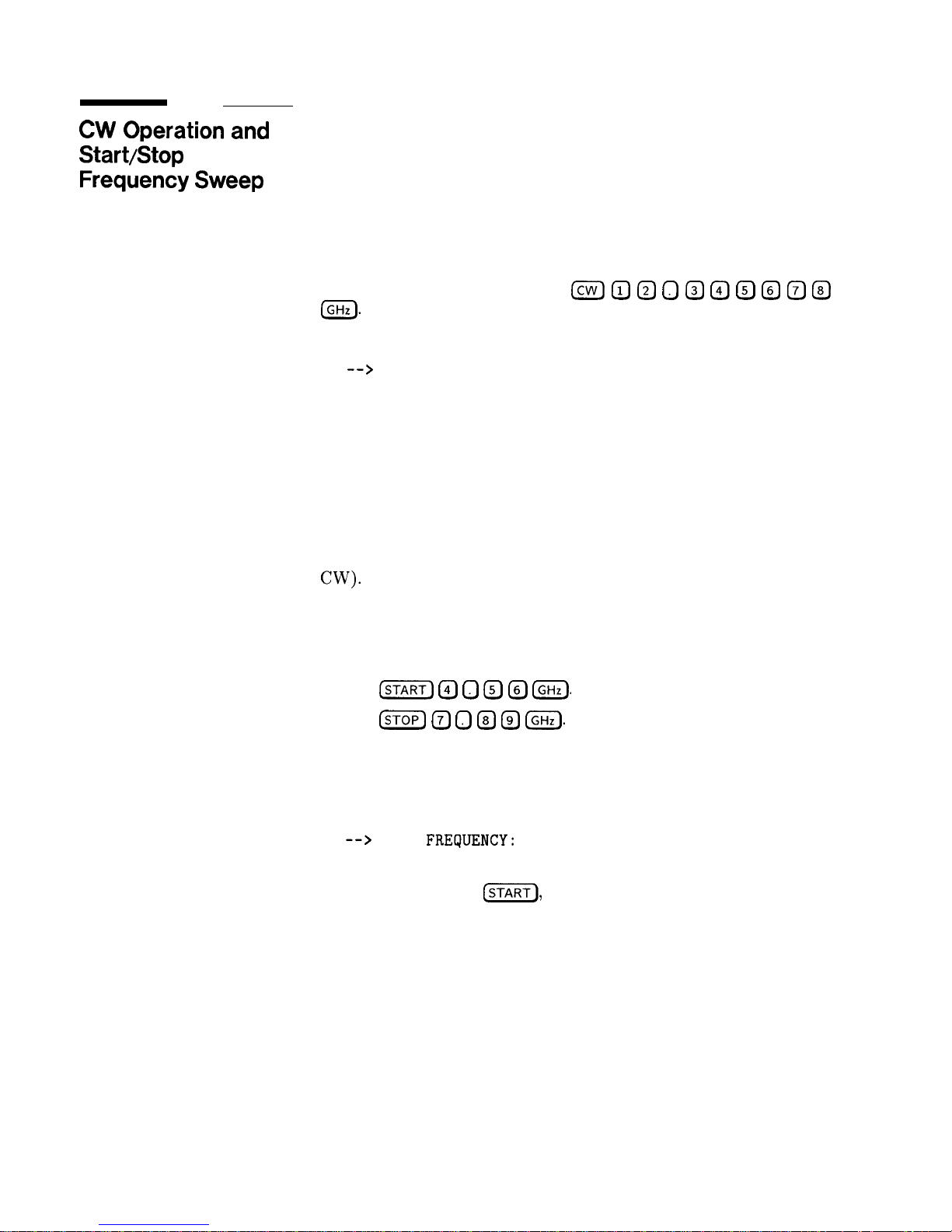
Figure 1-4. CW Operation and Start/Stop Frequency Sweep
CW Operation
start/stop
Frequency Sweep
1. Press
[cw).
1. Press
@iZF).
2. Enter value.
2. Enter value.
3. Press terminator key.
3. Press terminator key.
4. Press (STOP).
5. Enter value.
6. Press terminator key.
Getting Started Basic 1-7
Page 35
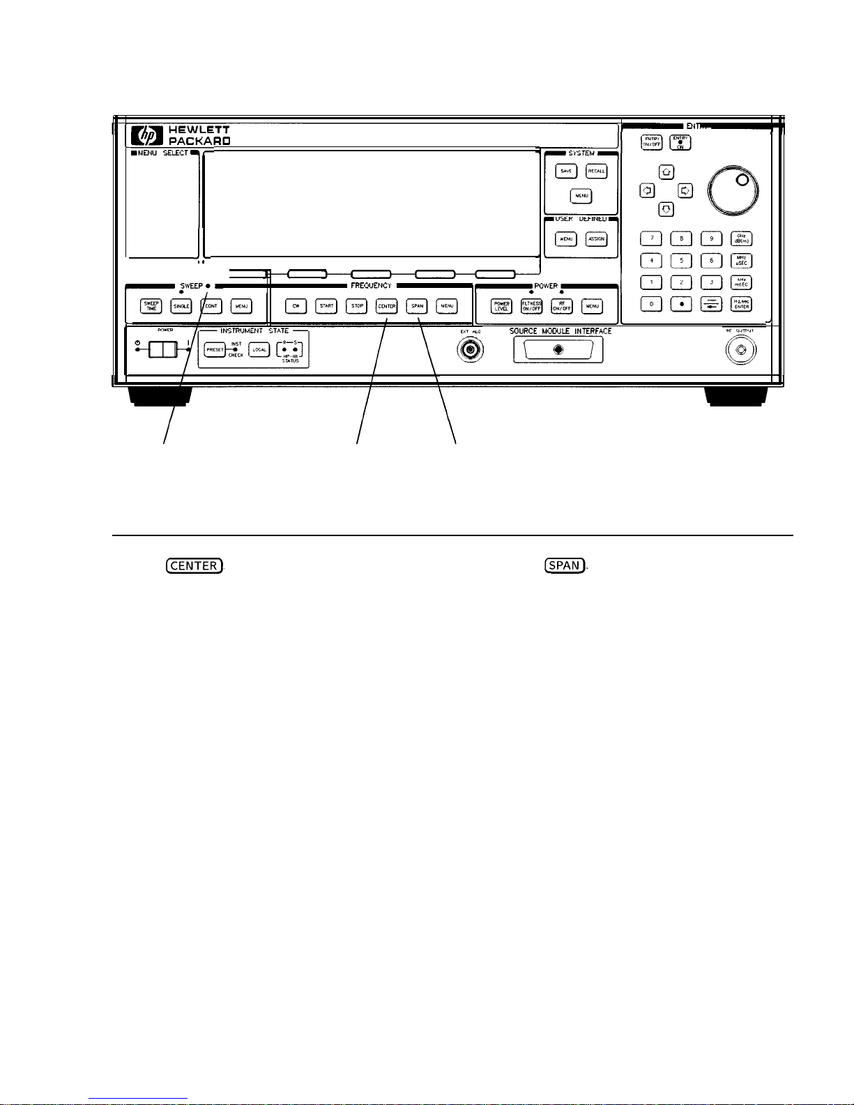
Center
Center frequency/span is another way of establishing swept
- ------
Frequency/Span
dperation
operation. This is just a different way of defining sweep limits. As an
example of center frequency/span operation:
Press
m@
(GHz).
Press (SPAN)
(iJ IGHz).
The swept CW generator is now sweeping from 3.5 to 4.5
GHz
(to
view these figures, press either (START) or (STOP), then
ml).
The
data display area indicates the center frequency, as well as, the span.
Notice that the green SWEEP LED is on.
While span is the active function, try the rotary knob and arrow
keys. This symmetrical increase or decrease of the frequency span
about the center frequency is one reason that center frequency/span
swept operation is used instead of start/stop frequency sweep.
Another example illustrates the subtleties of center frequency/span.
Press (CENTER) @
(GHz)
Press (SPAN @
IGHz)
Notice that the center frequency changed. This is because the center
frequency could not accommodate a span of 8 GHz without exceeding
the lower frequency limit of the swept CW generator’s specified
frequency range. If the low or high frequency range limits are
exceeded, the inactive (center or span) function is reset. Experiment
with the rotary knob and the arrow keys as alternate methods of
data entry.
1-8 Getting Started Basic
Page 36
1 y[!&i$i--
-
.
:ARO
.
’
JI
I
C
2
1
FREQUENCY
SOURCE MOWLE INTERFACE
SWEEP LED
CENTER
SPAN
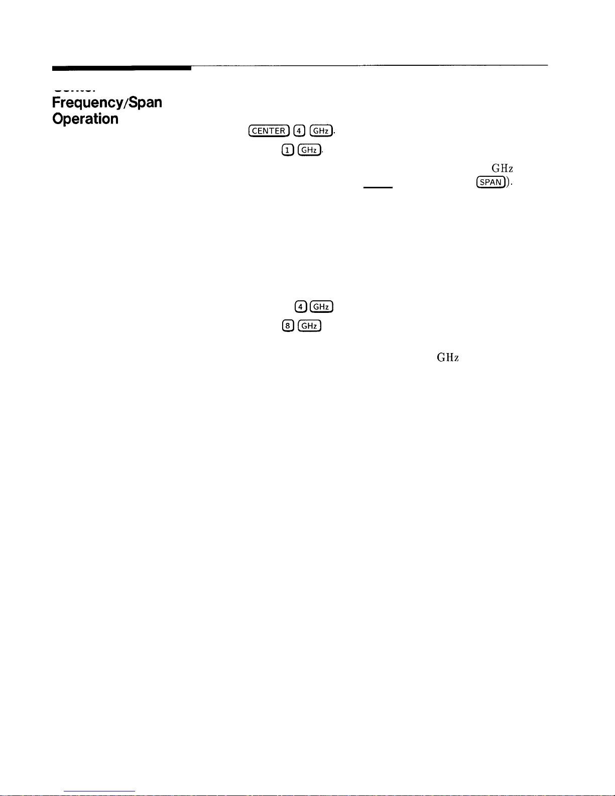
Figure 1-5. Center Frequency and Span Operation
Center Frequency
Operation
Span Operation
1. Press
@?TiiFj,
2. Enter value.
1. Press
m).
2. Enter value.
3. Press terminator key.
3. Press terminator key.
Getting Started Basic 1-9
Page 37
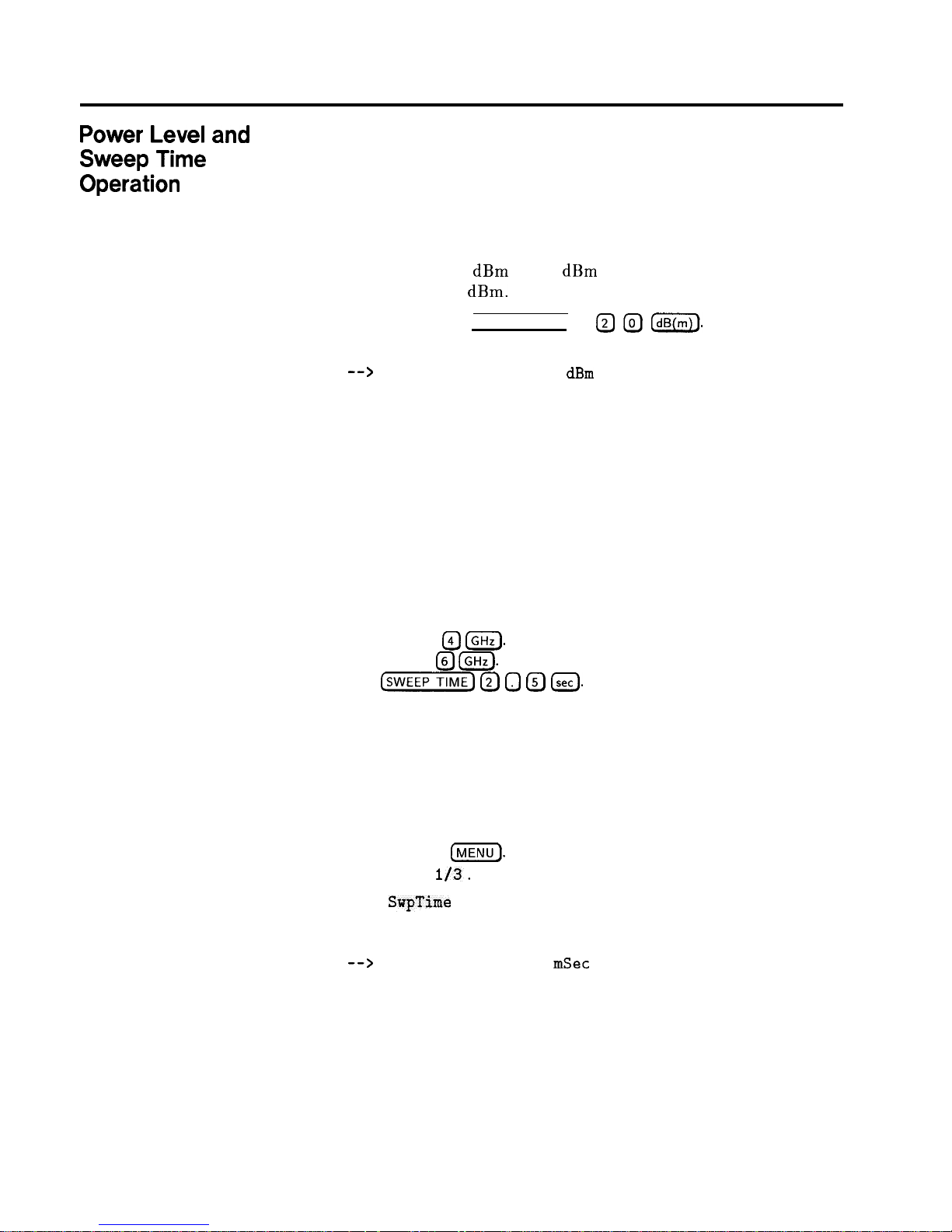
Power Level and
Sweep Time
Operation
Power Level Operation
The swept CW generator can produce leveled power for CW, swept
frequency, or power sweep operation. The selected power level
can range from -20
dBm
(-110
dBm
for Option 001 swept CW
generators) to -l-25
dBm.
For practice: Press [POWER LEVEL] I-) @ @
m.
The active entry
area shows:
-->
POWER LEVEL: -20.00
dBm
If the selected power level is beyond the range of the swept CW
generator, the closest possible power is shown in both the data
display area and the active entry area. If the selected power level
exceeds the maximum leveled power the swept CW generator is
able to produce, the unleveled message UNLVLED appears on the
message line. Experiment with the rotary knob and the arrow keys
as alternate methods of data entry.
Sweep Time Operation
In typical applications the sweep time can vary tremendously, from
milliseconds in a network analyzer system, to more than a minute in
thermistor-based power meter systems.
Press (START) @
IGHz).
Press (STOP) @
(GHz).
Press
lsWEEP
(Y?J 0 @ (,,,I.
Watch the green SWEEP LED, it blinks every 2.5 seconds. The LED
blinks at each retrace.
For the fastest sweep speed for which all specifications are
guaranteed, the swept CW generator must be in automatic sweep
time selection.
Refer to menu map 7, SWEEP.
Press SWEEP
I=).
Select more
l/3.
Select
SwpTime
Auto .
Notice that the active entry area indicates:
-->
SWEEP TIME:
100.0
mSec
AUTO
When the swept CW generator is in automatic sweep time selection,
the active entry area displays AUTO along with the current sweep
time. Faster sweep speeds than this are possible, turn the rotary
knob counter-clockwise until the display no longer changes. Notice
that AUTO is no longer displayed.
l-10 Getting Started Basic
Page 38
HEWLETT
PACKARO
se..Ecr’l
,
INSTRUMENT SrATE -
IF OUTPVT
SWEEP TIME
SWEEP LED
POWER LEVEL
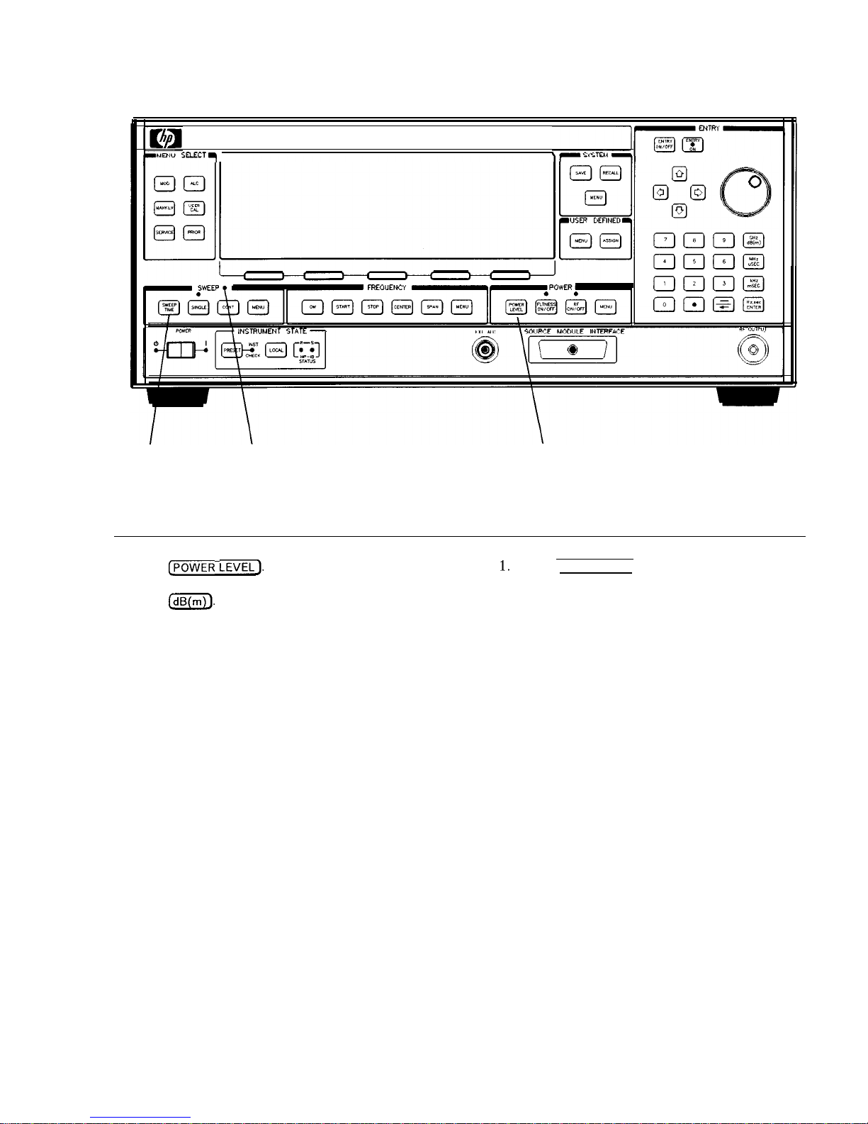
Figure 1-6. Power Level and Sweep Time Operation
Power Level
Sweep Time
Operation
Operation
1.
Press ~POWER
LEVEL].
1. Press
SWEEP TIME
2.
Enter value.
2. Enter
value.
3.
Press
0.
3. Press
terminator key.
Getting Started Basic l-11
Page 39

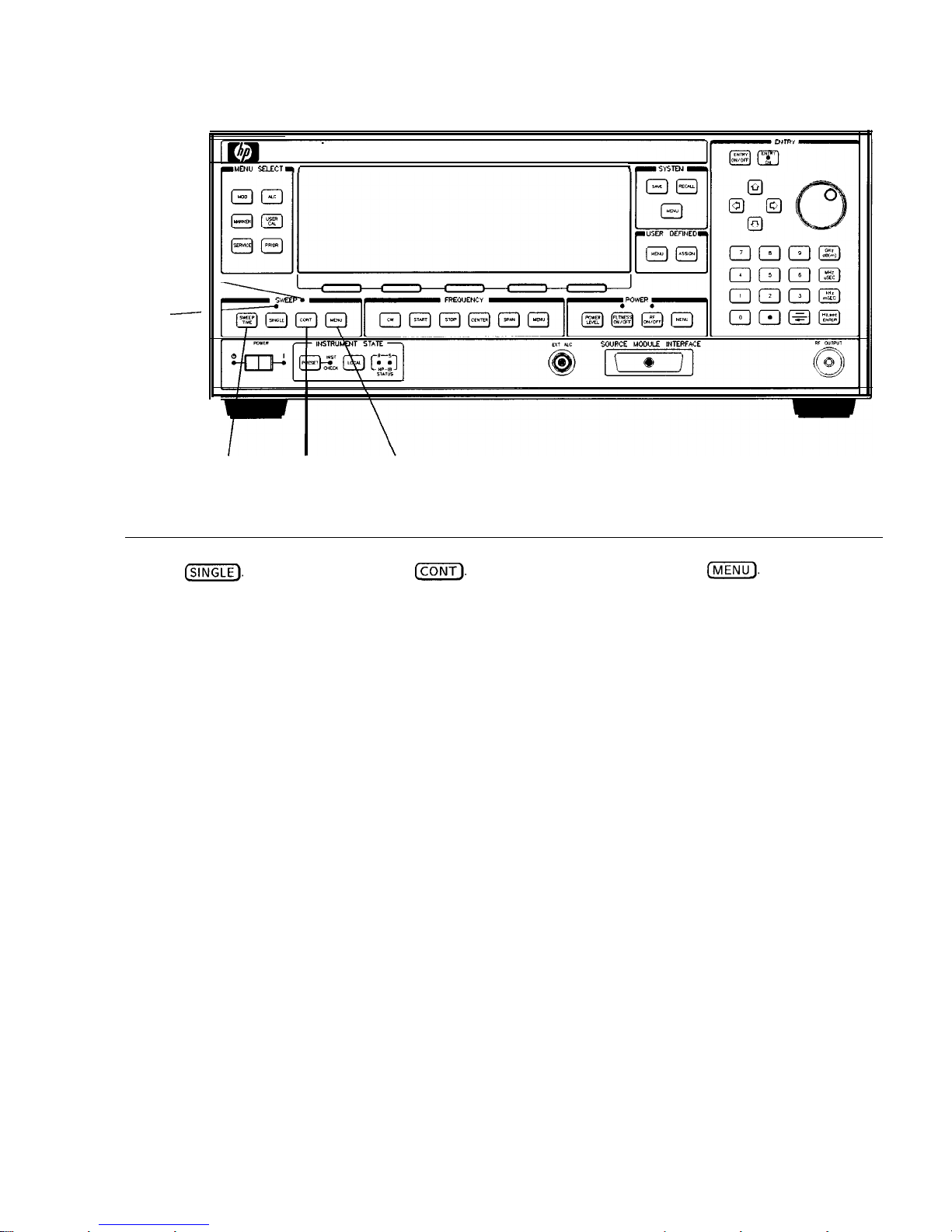
Continuous,
and Manual
Operation
Single,
Continuous sweep is the operation mode set when the swept
Sweep
CW generator is preset. It simply means that when the swept
CW generator is performing a swept operation, the sweeps will
continuously sweep-retrace-sweep-retrace until a different sweep mode
is selected. To choose this sweep mode, press
(CONT).
To change from continuous sweep to single sweep operation, press
(SINGLE). This causes the swept CW generator to abort the sweep in
progress and switch to the single sweep mode. This initial keystroke
causes the swept CW generator to switch sweep modes, but it does
not initiate a single sweep. A second keystroke (press (SINGLE))
initiates a single sweep. When the swept CW generator is in single
sweep operation, the amber LED above the key lights. When the
swept CW generator is actually performing a sweep in single sweep
mode, the green SWEEP LED lights.
The manual sweep mode lets you use the rotary knob to either sweep
from the start frequency to the stop frequency or to sweep power.
Refer to menu map 7, SWEEP.
Press
(PRESET).
Press SWEEP (MENU).
Select Manual Sweep.
The active entry area displays:
-->
SWEPT MANUAL: XXXXXXXXX MHz
Use the rotary knob to sweep from the start to the stop frequency.
The green SWEEP LED is off in manual sweep mode because the
sweeps are synthesized.
1-12 Getting Started Basic
Page 40
SWEEP
LED ----
SINGLE
-
LED
HEWLETT
PACKARD
LMENU m.ECT.,
SINGLE CONT
SWEEP MENU
Figure 1-7. Continuous, Single, and Manual Sweep Operation
Single Sweep
1. Press
@iETQ
Continuous Sweep
1. Press
ICONT).
Manual Sweep
1. Press SWEEP
IrV1ENU_).
2. Press Manual Sweep.
3. Use the rotary knob to adjust frequency.
Getting Started Basic 1-13
Page 41
Marker Operation
The swept CW generator has five frequency markers that can be used
as fixed frequency “landmarks,”
or as variable frequency pointers
on a CRT display. To view the marker features of the swept CW
generator on a CRT, connect the swept CW generator as shown in
Figure l-8.
Refer to menu map 3, MARKER.
Press
[m).
Press (START) @
(GHzl.
Press
ISTOP) @ (GHz).
Press [MARKER).
Select Marker Ml and enter @
LGHz).
The swept CW generator is sweeping from 3 to 7 GHz, with a 100 ms
sweep speed. A frequency marker is set at 4 GHz, which causes an
intensified dot to appear on the CRT. To obtain an amplitude spike
at that frequency, select
Amp1
Markers . Notice that you can set the
amplitude of the spike with the rotary knob or entry keys. To return
to the intensified dot representation, select
Amp1
Markers (asterisk
off).
Caution
Amplitude markers increase the output power at the marker
frequency. Provide protection to devices that could be damaged.
For a second marker, select Marker M2 and enter @ 0 @
(GHz).
This process can be continued for all five markers. Note that the
marker displayed in the active entry area is “active” and can be
controlled by the rotary knob, arrow keys, and numeric entry keys.
Once the Ml and M2 markers are established, the marker sweep
function,
softkey
Ml--M2 Sweep, temporarily changes the original
start/stop frequencies to those of markers Ml and M2. Select
Ml--M2 Sweep.
Notice that the swept CW generator now is
sweeping from 4 to 5.5 GHz. Use this function to focus in on a
selected portion of the frequency sweep. Select Ml--M2 Sweep again.
This turns the function off and returns the swept CW generator to
its original sweep parameters. To change the start/stop frequencies
for the swept CW generator, not just temporarily, use the softkey
Start=Ml Stop=M2.
As an example of the delta marker function:
Select
Marker
M3
and enter @ 0
am.
Select
Delta Marker.
The frequency difference between marker 3 and marker 1 is displayed,
and the CRT trace is intensified between the two markers. The active
entry area displays:
-->
DELTA MKR (3-l) : 2700.000000 MHz
1-14 Getting Started Basic
Page 42

Marker 1 was chosen because it is selected as the delta marker
reference. To change reference markers, select Delta Mkr Ref .
Select M2 as the reference. Watch the display change to indicate:
-->
DELTA MKR
(3-2)
: 1200.000000 MHz
You can choose any of the five markers as a reference, but when delta
marker is on, if the reference marker has a frequency value higher
than the last active marker, the difference between the frequencies is
negative and is displayed as such by the swept CW generator. The
CRT display continues to intensify the difference between the two
markers.
When delta marker is showing in the active entry area, the ENTRY
area is active. Rotate the rotary knob and watch the frequency
difference change. The last active marker (in this case, marker 3)
changes frequency value, not the reference marker.
OSCILLOSCOPE
Figure 1-8. Marker Operation
Marker Operation
Delta Marker
Operation
1. Press
(jiXi?K).
2. Select a marker key (Ml .
MS
).
3. Enter value.
4. Press terminator key.
1. Press
($iZKKj.
2. Select a marker key (MI
~5).
3. Enter value.
4. Press terminator key.
5. Select a different marker key ( Mi M5 ).
6. Enter value.
7. Press terminator key.
8. Select Delta
Hkr
Ref.
9. Select one of the previously chosen markers.
10. Press
IPRIOR).
11. Select Delta Marker
Getting Started Basic l-15
Page 43

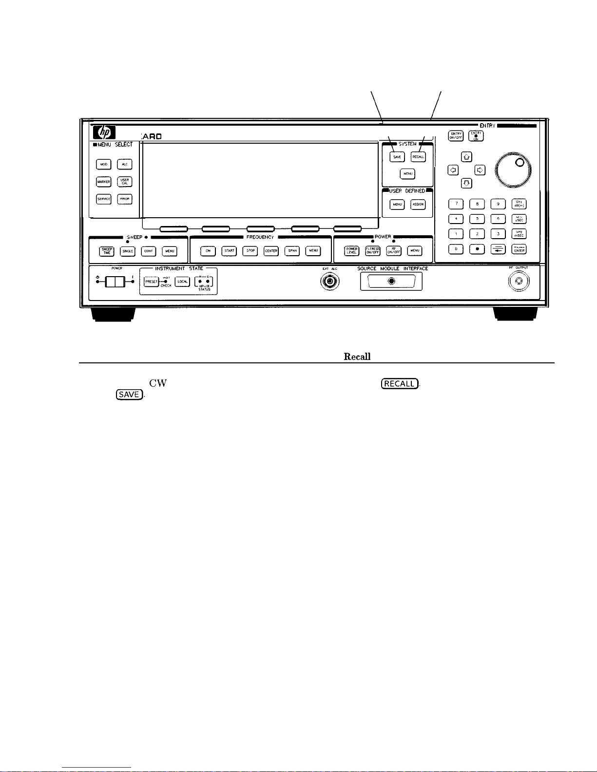
Saving and
The save/recall registers store and access a previously set instrument
Recalling an
state.
Instrument State
For example, set the swept CW generator to sweep from 3 to 15
GHz at a -10 dB power level, with markers 1 and 2 set at 4.5 and
11.2 GHz.
Press (START)
(?J LGHz).
Press
LSTOP) (iJ @ (GHz).
Press (POWER LEVEL)
(-) (iJ (TJ IdBo).
Press
(MARKER).
Select Marker Ml
@ 0 @ IGHz).
Select Marker M2
(iJ 0 0 @ LGHz).
To save this instrument state in register 1, press
(SAVE]
(iJ. To verify
that the swept CW generator has saved this state:
Press
[PRESET).
Press
IRECALL] 0.
Press
(MARKER).
The active entry area displays:
-->
RECALL REGISTER: 1 RECALLED
Notice the sweep end points, power level, and the asterisks next to
the marker 1 and 2 key labels.
You can save instrument states in registers 1 through 8. Register
0 saves the last instrument state before power is turned off. When
power is turned on, register 0 is automatically recalled.
1-16 Getting Started Basic
Page 44
m
HEWLETT
PACK
IARC
IlMENU SELPX
1
SAVE
RECALL
\ /II
ENrRRy -
USER
DEWED
Figure 1-9. Saving and Recalling an Instrument State
Save
1. Set up swept CW generator as desired.
2. Press
ISAVE).
3. Press a number
1
through 8.
Recall
1. Press
IjZKiJ.
2.
Press a number0through
8.
Getting Started Basic l-17
Page 45

Power Sweep and
Pow& Slope
Operation
Power Sweep Operation
The power sweep function allows the power output to be swept
(positive or negative) when the swept CW generator is in the CW
frequency mode. The power output of the swept CW generator
determines the maximum leveled power sweep that can be
accomplished. For this example, refer to the “Menu Map” section.
Zero and calibrate the power meter.
Connect the instruments as shown in Figure l-10.
Press
Icw @ IGHz).
Press (POWER LEVEL)
@ m.
Press (SWEEP
TIME) (TJ (,,,)
(SINGLE).
Set the power meter to dB[REF] mode.
The swept CW generator is ready to produce a 4 GHz CW signal
at 0
dBm
power out, with a 2 second sweep rate whenever a single
sweep is executed. The power meter is ready to measure the power
level relative to a starting point of 0
dBm.
Press
POWER,[jKQ
Select Power Sweep and enter 0
(dB(m))
(asterisk on).
Press (SINGLE).
Watch the relative power indication on the power meter. At the end
of the sweep the power meter indicates +7 dB. The active entry area
on the swept CW generator indicates:
-->
POWER SWEEP:
7.00 dB/SWP
Now enter @ @
(dB(mLj)
(p
ower sweep is still the active entry
function).
Press [SINGLE).
This time the power meter indicates less than the power sweep
requested. Note that the swept CW generator is unleveled, UNLVD.
This happens because the swept CW generator’s output power at the
start of the sweep is 0 dB and the requested power sweep takes the
swept CW generator beyond the range where it is able to produce
leveled power. The range of the power sweep is dependent on the
ALC range and can be offset if a step attenuator (Option 001) is
present.
Select Power Sweep to turn this function off (no asterisk).
Press
(POWER LEVEL)
I-] @
@.
On the power meter, press dB[REF] to reset the reference level.
1-18 Getting Started Basic
Page 46

Select power Sweep (asterisk on).
Press
@GE).
The swept CW generator performs a power sweep beginning at
-20
dBm
and ending at +5
dBm.
The power meter indicates
+25
dB.
Power Slope Operation
This function allows for compensation of high frequency system or
cable losses by linearly increasing the power output as the frequency
increases. For this example, refer to the “Menu Map” section.
Press Power Slope, the active entry area displays:
-->
RF SLOPE:X. XX
dB/GHz,
where X is a numeric value.
Power slope is now active, notice that an asterisk is next to the key
label.
Use the entry keys, rotary knob, or arrow keys to enter a value for
the linear slope.
Press Power Slope again to turn this feature off.
SUEPT
CU
GENERFITOR
\
POUER HETER
I
RF OUTPUT
AGAPTER
POWER SENSOR
Figure l-10. Power Sweep and Power Slope Operation
Power Sweep
Power Slope
1. Press POWER
(jj).
1. Press POWER
(&ii@.
2. Select Power Sweep.
2. Select Power Slope.
3. Enter a value.
3. Enter a value.
4. Press terminator key.
4. Press terminator key.
Getting Started Basic 1-19
Page 47

Advanced
Getting Started
Advanced
This section of Chapter 1 describes the use of many of the unique
features of the HP 8360 L-Series Swept CW Generators. The format
used is similar to the one used on the previous pages. When referred
to a menu map number, go to the Menu Map tab and unfold the
menu map so that you can view it together with the text.
Some menus have more than one page of softkeys. Select the
more
m/n softkey
to view the next page of softkeys. more m/n is
not included in the keystrokes given in these procedures.
Table l-l. Keys Under Discussion in This Section
Paragraph Heading Keys
Externally Leveling the Swept CW Generator Leveling Point ExtDet
Coupling Factor
POWER LEVEL
Set
Atten
Leveling Point
PwrMtr
Pwr Mtr Range
Leveling Point Module
Mdl Lev Menu
Working with Mixers/Reverse Power Effects
Uncoupl Atten
Leveling Mode Normal
Working with Spectrum Analyzers/
Leveling Mode ALCoff
Reverse Power Effects
Leveling Mode Search
“Optimizing Swept CW Generator Performance” Fltness Menu
Delete Menu
Auto Fill Start
Auto Fill Stop
Auto Fill
Incr
Mtr
Meas
Menu
FLTNESS ON/OFF
Enter Freq
Enter Corr
Freq Follow
List Menu
Copy List
Sweep Mode List
Ext Det Cal
Getting Started Advanced 1-21
Page 48

Advanced
Table 1-1.
Keys Under Discussion in This Section (continued)
Paragraph Heading
Keys
‘Optimizing Swept CW Generator Performance” Auto Track
:ontinued Peak RF Always
Peak RF Once
Sup
Span Cal Once
Sup
Span Cal Always
FullUsr
Cal
Jsing Step Sweep
>reating and Using a Frequency List
Jsing the Security Features
2hanging the Preset Parameters
USER DEFINED MENU
ASSIGN
Step
Sup
Menu
List Menu
Delete Menu
Enter List Freq
Enter List Offset
Enter List Dwell
Pt Trig Menu
Zero Freq
Save Lock
Clear Memory
Blank Display
Save Usr Preset
Preset Mode User
PRESET
For more information, each of these keys has a separate entry in
Chapter 2.
1-22 Getting Started Advanced
Page 49
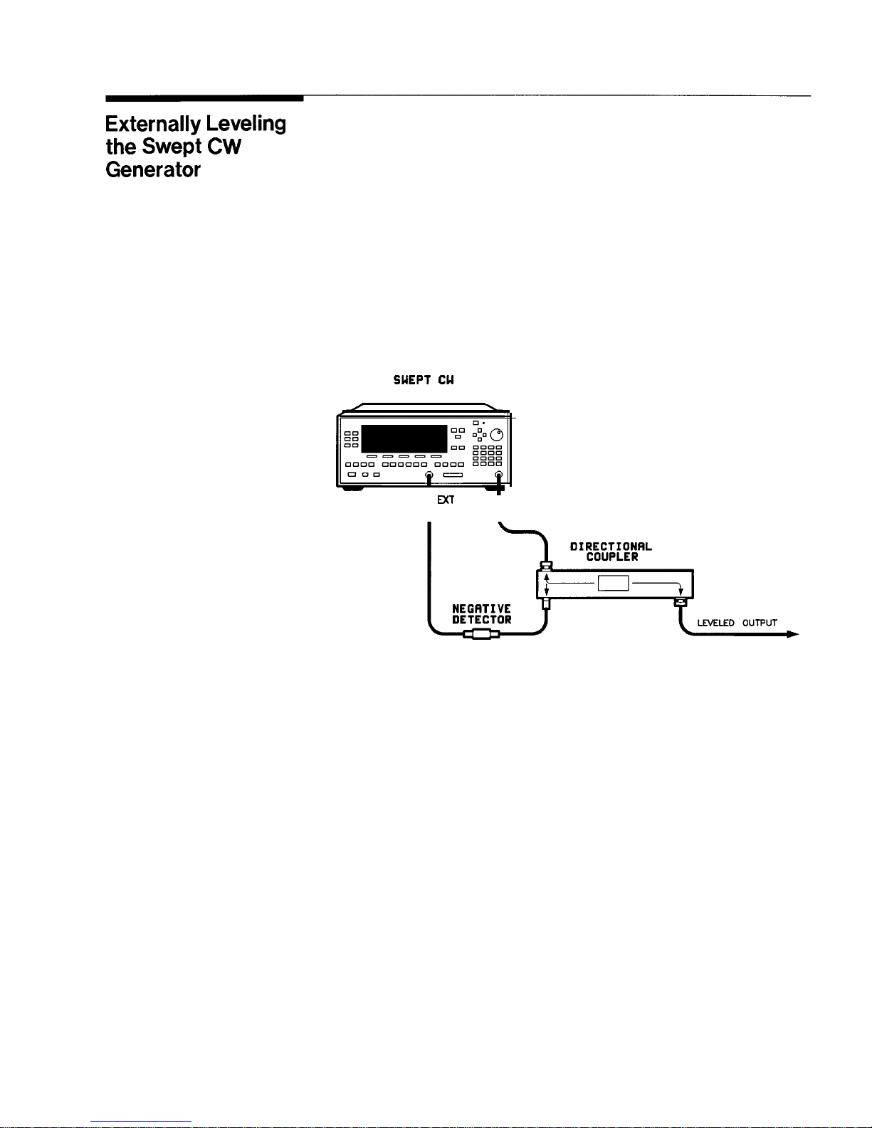
Externally Leveling
the Swept CW
Generator
In externally leveled operations, the output power from the swept
CW generator is detected by an external sensor. The output of this
detector is returned to the leveling circuitry, and the output power
is automatically adjusted to keep power constant at the point of
detection.
Leveling with
Figure l-11 illustrates a typical setup for external leveling. When
Detectors/Couplers
externally leveled, the power level feedback is taken from the external
/Splitters
negative detector input rather than the internal detector. This
feedback voltage controls the ALC system to set the desired RF
output. Refer to Figure A-l in Chapter 2 for a block diagram of the
swept CW generator’s ALC circuitry.
SUEPT CU
GENERATOR
p-
I
I
MT
I
RF OUTPUT
ALC
Figure l-l 1. ALC Circuit Externally Leveled
Getting Started Advanced 1-23
Page 50
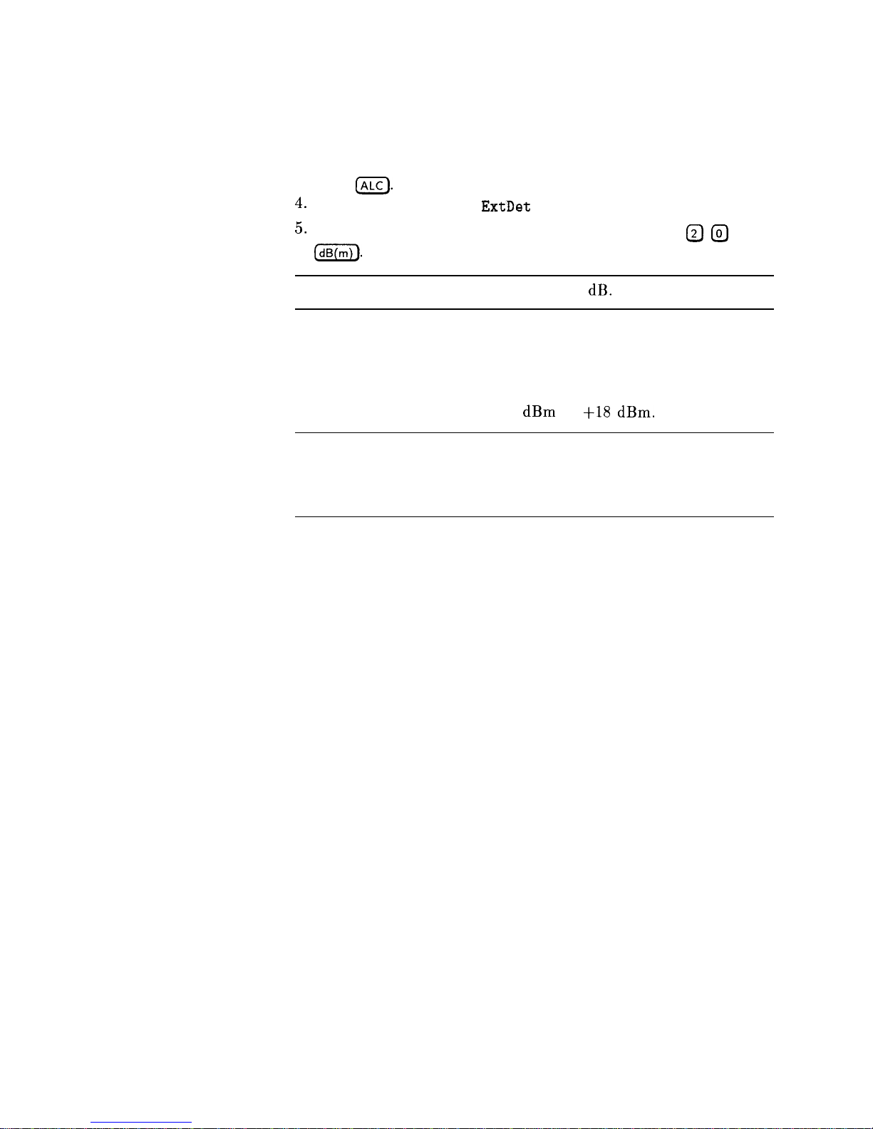
To level externally:
1. Set up the equipment as shown. For this example, the
detector/coupler setup is used.
2. Refer to menu map 1.
3. Press
(ALC).
4.
Select Leveling Point
ExtDet
.
5.
Set the coupling factor. Select Coupling Factor I-) @
@
(dB(m)).
Note
Power splitters have a coupling factor of 0 dB.
Figure 1-12 shows the input power versus output voltage
characteristics for typical HP diode detectors. From the chart,
the leveled power at the diode detector input resulting from any
external level voltage setting may be determined. The range of power
adjustment is approximately -30
dBm
to
+18 dBm.
Hint
Automatically characterize and compensate for the detector used
by performing a detector calibration. Refer to “Using Detector
Calibration” in the “Optimizing Swept CW Generator Performance”
section.
1-24 Getting Started Advanced
Page 51
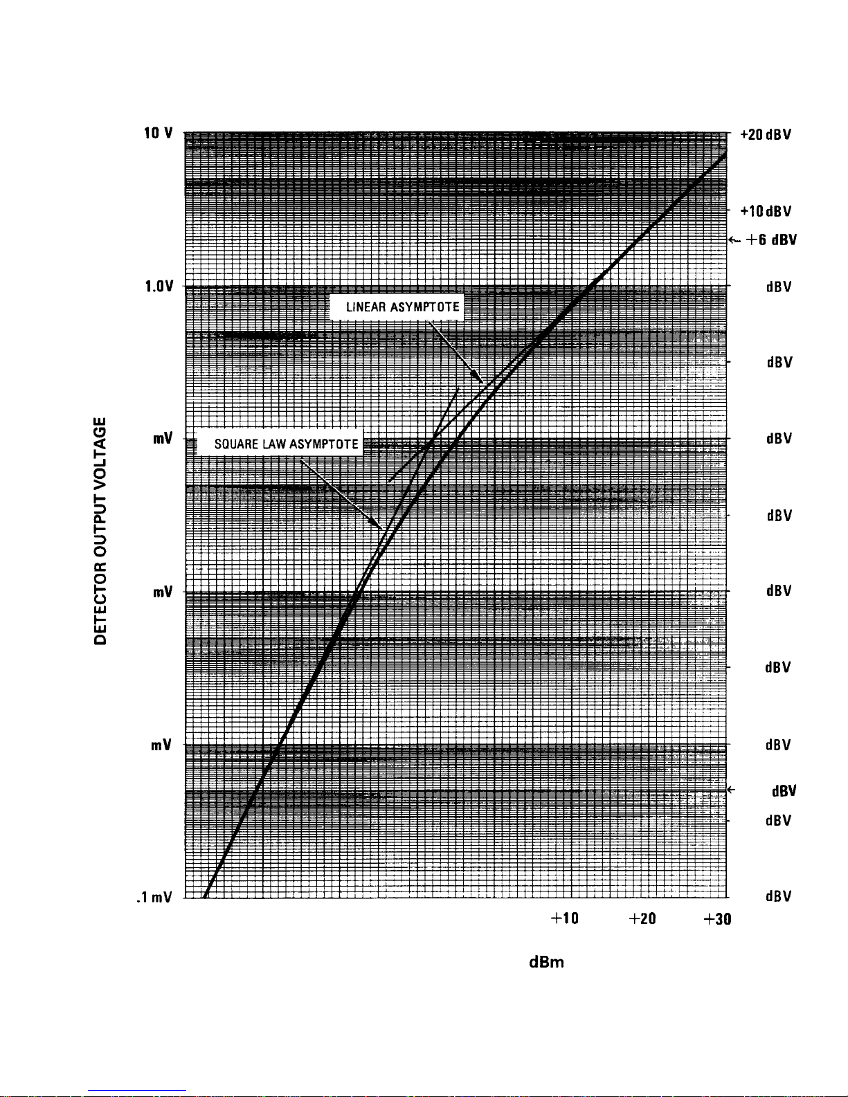
100
mV
10
mV
1
mV
.l
mV
+20 dBV
+lO
dBV
- +6
dBV
0
dBV
-10
dBV
-20
dBV
-30
dBV
-40
dBV
-50
dBV
-60
dBV
--66
dBV
-70
dBV
-80
dBV
40
-30 -20
-10
0
+10 +20
+30
DETECTOR INPUT POWER, dBm
Figure 1-12. Typical Diode Detector Response at 25°C
Getting Started Advanced 1-25
Page 52
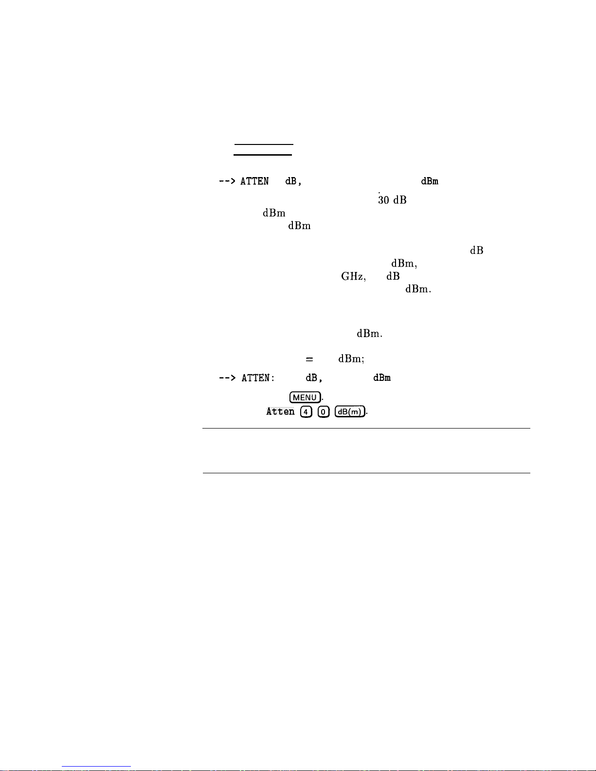
External Leveling Used With the Optional Step Attenuator
Some external leveling applications require low output power from
the swept CW generator. The swept CW generator automatically
uncouples the attenuator from the ALC system for all external
leveling points.
Press (POWER LEVEL). Note the display. It shows:
--> ATTEN
0 dB, POWER LEVEL: 0.00
dBm
For example, leveling the output of a 30 dB gain amplifier to a
level of -10
dBm
requires the output of the swept CW generator
to be around -40
dBm
when leveled. At some frequencies this
level is beyond the range of the ALC modulator alone. If so, the
LOW UNLVLED warning message is displayed. Inserting 40 dB of
attenuation results in an ALC level of 0
dBm,
which is well within
the range of the ALC. At 20 GHz, 30 dB attenuation is a better
choice as it results in an ALC level of -10
dBm.
This gives a margin
for AM or other functions that vary the power level.
For optimum display accuracy and minimum noise, the ALC
level should be greater than -10
dBm.
This is achieved by using
attenuation equal to the tens digit of output power. Example:
desired output power = -43 dBm; use:
--> ATTEN:
40
dB,
ALC -3
dBm
1. Press POWER
[MENU).
2. Select Set
Atten @ @ [my).
Hint
To obtain flatness corrected power, refer to “Creating and Applying
the User Flatness Correction Array” in the “Optimizing Swept CW
Generator Performance” section.
1-26 Getting Started Advanced
Page 53

Leveling with Power
Leveling with a power meter is similar to leveling with a diode
Meters
detector. Figure 1-13 shows the setup for power meter leveling.
SUEPT
CU
GENERATOR
LEVELED OUTPUT
POUER SPLITTER
DlRECllONAl COUPLER
Figure 1-13. Leveling with a Power Meter
1. Set up the equipment as shown. Be sure to set the power meter to
manual range mode and note the range.
2. Refer to menu map 1.
3. Press
LALC).
4.
Select Leveling Point PwrMtr .
5.
Select Pwr Mtr Range . Enter the range value set for the power
meter as noted in step 1.
6. Select Coupling Factor, press @
(dB(mZ).
Unlike detector leveling, power meter leveling provides calibrated
power out of the leveled RF port.
Hint
To obtain flatness corrected power, refer to “Creating and Applying
the User Flatness Correction Array” in the “Optimizing Swept CW
Generator Performance” section.
Getting Started Advanced 1-27
Page 54
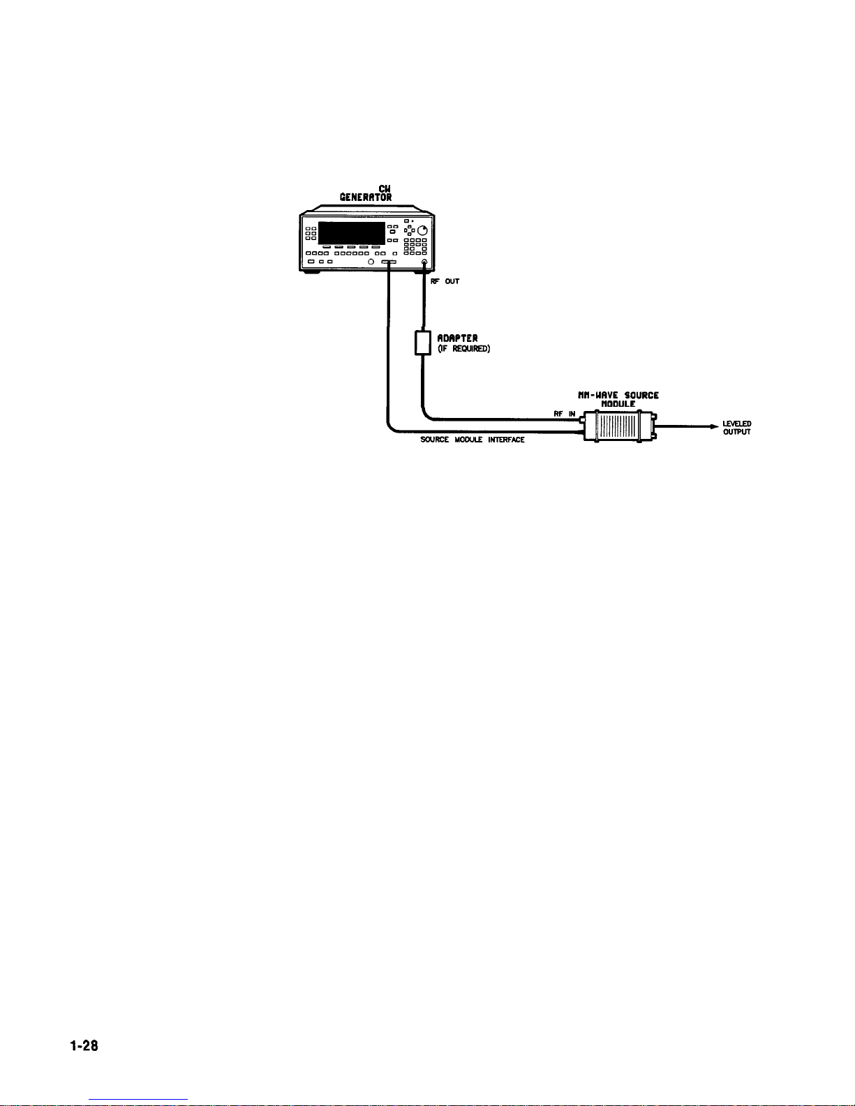
Leveling with MM-wave
Millimeter-wave source module leveling is similar to power meter
Source Modules
leveling. The following figures illustrate the setups for leveling with a
mm-wave source module.
WEPT
Cl4
GENERIWOR
P
RDAPTER
(IF REQUIRED)
Figure 1-14. MM-wave Source Module Leveling
High power model swept CW generators can externally level
mm-wave source modules to maximum specified power without a
microwave amplifier.
l-28
Getting Started Advanced
Page 55
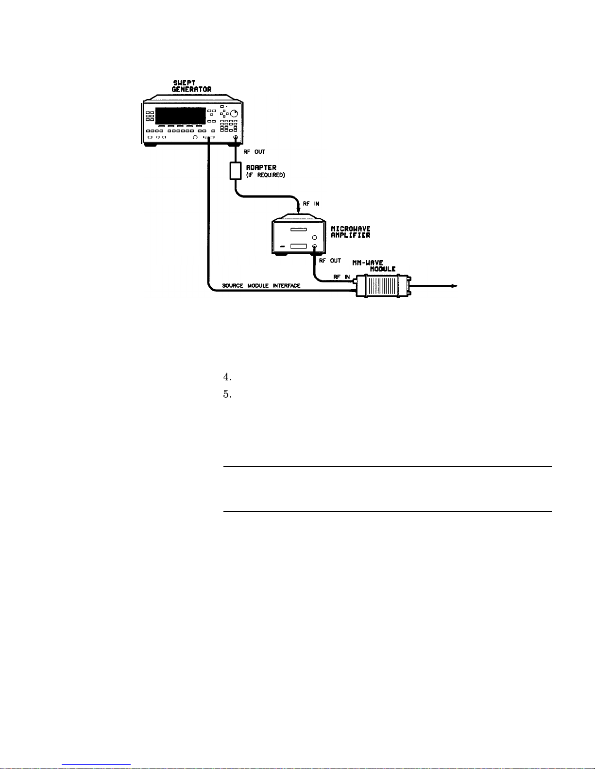
WEPT
CU
GENERRTOR
tlICROUAVE
AflPLIFIER
Ml-UAVE
SOURCE
LEVELED
OUTPUT
Figure 1-15. MM-wave Source Module Leveling Using a Microwave Amplifier
1. Set up the equipment as shown.
2. Refer to menu map 1.
3. Select Leveling Point Module.
4.
Select Module Menu.
5.
Select Module Select Auto or Front or Rear, depending on
where the interface connection is made.
All of the ALC data necessary to communicate properly with the
swept CW generator is exchanged via the SOURCE MODULE
INTERFACE.
Hint
To obtain flatness corrected power, refer to “Creating and Applying
the User Flatness Correction Array” in the “Optimizing Swept CW
Generator Performance” section.
Getting Started Advanced 1-29
Page 56

Working with
Mixers/Reverse
Power Effects
Note
Uncoupled operation applies to Option 001 swept CW generators
only.
Uncoupled operation is useful when working with mixers. Figure 1-16
shows a hypothetical setup where the swept CW generator is
providing a small signal to a mixer. The swept CW generator output
is -8
dBm,
which in Leveling Mode Normal results in
ATTEN =
0 dB, ALC Level = -8
dBm.
The mixer is driven with an LO of
+lO dBm,
and has LO to RF isolation of 15 dB. The resulting LO
feedthrough of -5
dBm
enters the swept CW generator’s OUTPUT
port, goes through the attenuator with no loss, and arrives at the
internal detector. Depending on frequency, it is possible for most of
this energy to enter the detector. Since the detector responds to its
total input power regardless of frequency, this excess energy causes
the leveling circuit to reduce its output. In this example the reverse
power is actually larger than the ALC level, which may result in the
swept CW generator output being shut off.
Figure 1-17 shows the same setup, with uncoupled operation used to
produce the same -8
dBm
output. In this case,
ATTEN
= -10 dB,
ALC Level = +2
dBm.
The ALC level is 10 dB higher, and the
attenuator reduces the LO feedthrough by 10 dB. Thus the detector
sees a +2
dBm
desired signal versus a possible -15
dBm
undesired
signal. This 17 dB difference results in a maximum 0.1 shift in the
swept CW generator output level. To set the swept CW generator to
the attenuator uncoupled mode as discussed in this example, do the
following:
1. Press POWER (MENU).
2.
Select Set
Atten
and press
(iJ @ IdBo).
This step does two
things, it uncouples the attenuator from the rest of the ALC
system, and it lets you set an attenuator value, in this case, 10 dB.
3. Press [POWER LEVEL) @
[dB(m)).
This sets the ALC level to
+2
dBm.
For more information on the ALC or setting power level, refer to
(ALC)
or [POWER LEVEL) in Chapter 2.
l-30 Getting Started Advanced
Page 57
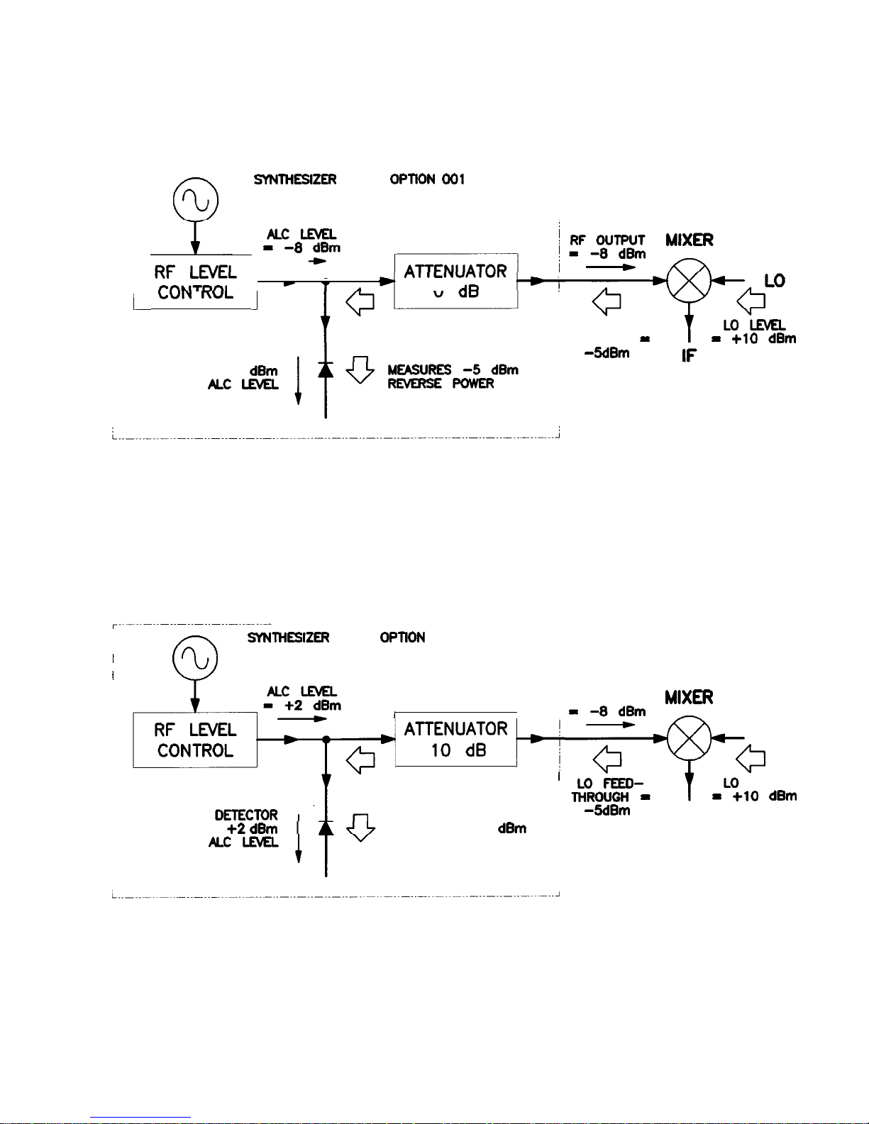
SwmEslfER WITH
OPnON
Do1
I
1
-0
I\1
LLVLL
I-II ILI.“T\I”I
r-n*monl
C
T
*
n
AD
i
LUIY
I
ITVL
J
t
LO FEED-
THROUGH
-
5dBm
DETECTOR
!
-
DETECTOR
MEASURES -8
dBm
ALC LmEL
=
+lO
dBm
Figure 1-16. Reverse Power Effects, Coupled Operation with -8dBm Output
r-~-------------------------
I
I
I
0
swmiEsl2ER
WITH
OPnON
001
%
MEASURES +2
dBm
I I
F+j ““:o”“goR
p-f
I
DETECTOR
MEASURES -15
dBm
REVERSE POWER
RF OUTPUT
MIXa
g-y-
LO
0
LO LEVEL
I
=
+lO
dBm
-5dBm
IF
Figure 1-17. Reverse Power Effects, Uncoupled Operation with -8dBm Output
Getting Started Advanced
1-3 1
Page 58

Working with
Reverse power is a problem with spectrum analyzers that do not
Spectrum
Analyzers/Reverse
Power Effects
have preselection capability. Some analyzers have as much as
+5 dBm
LO feedthrough coming out of their RF input, at some
frequencies. The effects of reverse power are less in the heterodyne
band (0.01 to 2.0 GHz) where the power amplifier provides some
broadband matching. Similarly, at frequencies above 2.0 GHz, reverse
power that is within 10 MHz of the swept CW generator’s frequency
may be partially absorbed by the YIG filter. If the frequency
difference is small enough to be within the leveling system bandwidth
(typically 10 kHz CW, 200 kHz sweep or AM), the effect of reverse
power is amplitude modulation of the swept CW generator’s output.
The AM rate equals the difference in RF frequencies. Reverse power
problems may be treated by using the unleveled mode. There are two
unleveled modes, ALC off and search.
To set the swept CW generator to the ALC off mode:
1.
Refer to menu map
1.
2. Press
IALC).
3.
Select Leveling Mode
ALCoff.
In this mode, the swept CW generator provides RF power with
no ALC correction and therefore requires a power meter to set a
particular power.
To set the swept CW generator to the search mode:
1. Press
m.
2.
Select Leveling Mode Search.
In this mode, the swept CW generator is in the normal ALC
mode until the desired power level is reached, then the ALC is
disconnected.
1-32 Getting Started Advanced
Page 59

Optimizing Swept
CW Generator
Performance
Creating and Applying
The following examples demonstrate the user flatness correction
the User Flatness
feature:
Correction Array
1. Using an HP 437B power meter to automatically enter correction
data for a swept 4 to 10 GHz measurement.
2. Manually entering correction data for a stepped (List Mode)
measurement.
3. Making swept mm-wave measurements, automatically entering
correction data for an arbitrary list of correction frequencies.
4. Making scalar analysis measurements with automatically-entered
correction data that compensates for power variations at the
output of a directional bridge.
Each example illustrates how to set up correction tables for a
different measurement requirement. Modify the instrument setups
shown to suit your particular needs. Completed correction tables
may be easily edited if more correction data is required for your
measurement. Additional correction frequencies may be added
by using the auto fill feature or by entering correction frequencies
individually. The auto fill feature adds but does not delete correction
frequencies.
There are two basic front-panel methods of creating a flatness
correction array. The first and quickest method is to use an HP 437B
power meter. Refer to Figure 1-18 for the setup. The second method
is just as accurate, but requires a little more interaction between the
operator and the instruments. Figure 1-19 shows the setup for the
second method.
Getting Started Advanced l-33
Page 60

mm
Creating a User Flatness Array Automatically, Example 1
In this example, a flatness array containing correction frequencies
from 4 to 10 GHz at 1
GHz
intervals is created. An HP 438B power
meter controlled by the swept CW generator through the interface
bus
For
1.
2.
3.
4.
5.
is used to enter the correction data into the flatness array.
this example, refer to menu map 5, POWER.
The equipment setup shown in Figure 1-18 assumes that if the
setup has an external leveling configuration, the steps necessary
to correctly level have been followed. If you have questions about
external leveling, refer to “Externally Leveling the Swept CW
Generator”.
Set up Power Meter
Zero and calibrate the power meter/sensor.
Enter the appropriate power sensor calibration factors into the
power meter.
Enable the power meter/sensor cal factor array. For operating
information on the HP 437B power, refer to its operating and
service manual.
Connect the power sensor to the point where corrected power is
desired.
HP-IE
I RND OTHER I
B-B
J
DEVICES ,
L
-I--
J
1 FLATNESS
I CORRECTED
, OUTPUT PORT
“q-p!--------A
------
POUEMEt&OR
J
HP 4378
POUER NE
I
I
DEVICE
UNDER
TEST
Figure l-18. Creating a User Flatness Array Automatically
TER
Note
No other devices can be connected to the HP-IB cable.
1-34 Getting Started Advanced
Page 61

Set up Swept CW Generator Parameters
6.
7.
8.
On the swept CW generator, press (PRESET).
FREQUENCY (START) @
LGHz),
(STOP) 0 @
(GHz).
(POWER LEVEL) @
(dB0).
Access User Flatness Correction Menu
9.
10.
Press POWER
(MENU).
Select
Fitness
Menu.
Select Delete Menu Delete All . This step insures that the
flatness array is empty.
11.
Press
(K).
Leave the delete menu and return to the previous
softkey
menu.
12.
Enter the frequency points at which the correction information
will be taken. Choose either the point-by-point entry method
Enter Freq or the automatic frequency point generation
Auto Fill Start. For this example, select Auto Fill Start
@[GHz).
13.
Select Auto Fill Stop 0 @
(GHz),
Auto Fill
Incr @ IGHz).
Notice that a frequency list starting at 4 and ending at 10 GHz
with an increment value of 1 GHz is created.
Enter Correction Data into Array
14.
Select Mtr
Meas
Menu Measure
Gorr
All . The power meter
is now under swept CW generator control and is performing
the sequence of steps necessary to generate the correction
information at each frequency point.
If an HP-IB error message is displayed, verify that the interface
connections are correct. Check the HP-IB address of the power
meter and ensure that it is the same address the swept CW
generator is using (address 13 is assumed). Refer to the menu
map 8, System, for the key sequence necessary to reach
softkey
Meter Adrs .
Enable User Flatness Correction
15.
When the operation is complete, (a message is displayed) the
flatness correction array is ready to be applied to your setup.
Disconnect the power meter/sensor and press (FLTNESS ON/OFF)
(amber LED on). Thep
ower produced at the point where the
power meter/sensor was disconnected is now calibrated at the
frequencies and power level specified above.
Getting Started Advanced 1-35
Page 62

Creating a User Flatness Array, Example 2
This example shows how to use the swept CW generator and a power
meter in manual entry mode. This example also introduces two
features of the swept CW generator. The
softkey
Freq Follow
simplifies the data entry process and the
softkey
List Mode sets up
a list of arbitrary test frequencies.
The frequency follow feature automatically sets the source to a CW
test frequency equivalent to the active correction frequency in the
user flatness correction table. The front panel arrow keys are used
to move around the correction table and enter frequency-correction
pairs. Simultaneously, the swept CW generator test frequency is
updated to the selected correction frequency without exiting the
correction table.
To further simplify the data entry process, the swept CW generator
allows you to enter correction data into the user flatness correction
table by adjusting the front panel knob until the desired power
level is displayed on the power meter. The user flatness correction
algorithm automatically calculates the appropriate correction and
enters it into the table. If you already have a table of correction data
prepared, it can be entered directly into the correction table using
the front-panel keypad of the swept CW generator.
With the list mode feature, you may enter the test frequencies into
a table in any order and specify an offset (power) and/or a dwell
time for each frequency. When list mode is enabled, the swept CW
generator steps through the list of frequencies in the order entered.
The user flatness correction feature has the capability of copying and
entering the frequency list into the correction table. Since the offset
in the list mode table is not active during the user flatness correction
data entry process, the value of the correction data is determined
as if no offset is entered. When user flatness correction and list
mode (with offsets) are enabled, the swept CW generator adjusts the
output power by an amount equivalent to the sum of the correction
data and offset for each test frequency. You must make sure that the
resulting power level is still within the ALC range of the swept CW
generator.
1-36 Getting Started Advanced
Page 63

SUEPT
CU
GENERATOR
--
, AND OTHER
,
B-B
J
DEVICES ,
L
-1--
J
1
FlATNE!is
I CORRECTED
, OUTPUT
PORT
2iTl-LL
-----
A
----
I I
DEVICE
UNDER
TEST
POUER METER
-P~ER%h&OR
)
Figure 1-19. Creating a User Flatness Array
For this example, refer to menu map 5, POWER.
1. The equipment setup shown in Figure 1-19 assumes that if your
setup has an external leveling configuration, the steps necessary
to correctly level have been followed. If you have questions about
external leveling, refer to “Externally Leveling the Swept CW
Generator”.
Set up Power Meter
2. Zero and calibrate the power meter/sensor.
3. Connect the power sensor to the point where flatness corrected
power is desired.
Set up Swept CW Generator Parameters
4. On the swept CW generator, press (PRESET).
5. [POWER LEVEL]
@ 0).
This sets the test port power to
+5
dBm (PO max - Ppath loss>.
Create A Frequency List
6. On the swept CW generator, press FREQUENCY
(MENU).
7.
Select List Menu Enter List Freq
@m.
This enters
5 GHz as the first frequency in the list array. Entering a
frequency automatically sets the offset to 0 dB and the dwell to
10 ms.
8. Enter 18, 13, 11, and 20 GHz to complete this example array.
Getting Started Advanced 1-37
Page 64

Access User Flatness Correction Menu
9. Press POWER
(E).
Select
Fitness
Menu.
10.
Select Delete Menu Delete All . This step insures that the
flatness array is empty.
11. Press
(El.
Leave the delete menu and return to the previous
soft key menu.
12. Select Copy List This step copies the frequency list into the
correction table in sequential order.
13.
Select Freq Follow.
This sets the swept CW generator to CW
frequency mode to facilitate taking correction information. As
you scroll through the correction cells, the swept CW generator
produces the corresponding CW frequency at 0 dBm.
14. Select Enter Corr . This
allows correction value entry.
15. Press
[FLTNESS
ON/OFF). This step enables user flatness correction.
16. For 5 GHz, set the appropriate power sensor cal factor on the
power meter.
17. Use the swept CW generator rotary knob to adjust for a
measurement of 0.00
dBm
on the power meter. Notice that a
correction value is entered at 5 GHz.
18. Use the up arrow key to increment to the next correction cell.
19. For 11 GHz, set the appropriate power sensor cal factor on the
power meter.
20. Use the swept CW generator rotary knob to adjust for a
measurement of 0.00
dBm
on the power meter.
21. Repeat this sequence of steps until all the frequency points have
a correction value entered.
Activate List Mode
22. Press SWEEP
(j).
Select Sweep Mode List .
23. The flatness correction array is ready to be applied to your setup.
Disconnect the power meter/sensor. The power produced at the
point where the power meter/sensor was disconnected is now
calibrated at the frequencies and power level specified above.
1-38 Getting Started Advanced
Page 65

Swept mm-wave Measurement with Arbitrary Correction Frequencies,
Example
3
The focus of this example is to use user flatness correction to
obtain flat power at the output of the HP 83550 series mm-wave
source modules. In this case we will use non-sequential correction
frequencies in a swept 26.5 to 40 GHz measurement with an
HP 83554 source module.
The time it takes for a large quantity of power meter measurements
can be long, therefore, we selected non-sequential correction
frequencies to target specific points or sections of the measurement
range that we assume are more sensitive to power variations. This
greatly expedites setting up the user flatness correction table. The
amount of interpolated correction points between non-sequential
correction frequencies varies. This example uses the HP 437B to
automatically enter correction data into the array.
Note
Turn off the swept CW generator before connecting to the source
module interface (SMI) cable, or damage may result.
Getting Started Advanced 1-39
Page 66
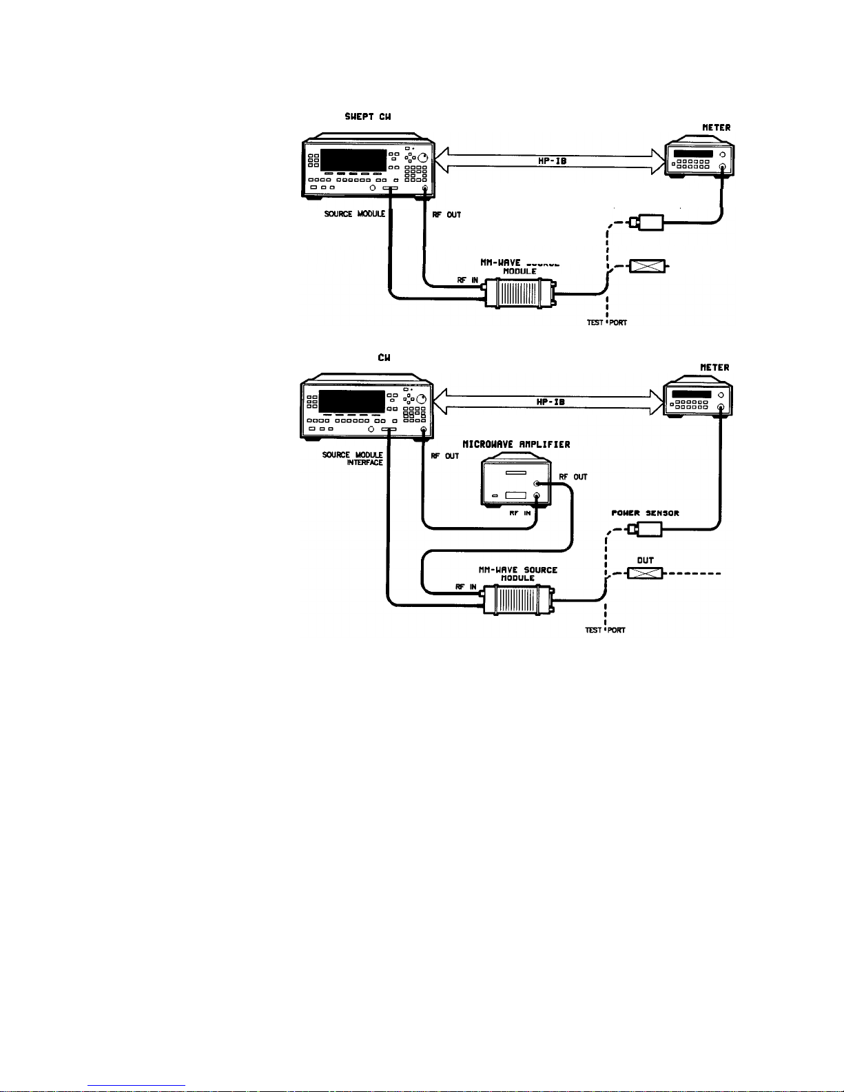
WEPT ELI
GENERRTOR
HP 4378
POUER
METER
POUER SENSOR
SUJRCE MODULE
I
I
FF OUT
INTERFACE
DUT
IIll-URVE
SOURCE
-m
-------
SUEPT
CU
GENERATOR
HP 4378
POWER
flEfER
NICROUAVE
RNPLIFIER
Figure l-20.
Creating Arbitrarily Spaced Frequency-Correction Pairs in a Swept mm-wave
Environment
For this example, refer to menu map 5, POWER.
1. The equipment setup shown in Figure l-20 assumes that
you have followed the steps necessary to correctly level the
configuration. If you have questions about external leveling, refer
to “Externally Leveling the Swept CW Generator”.
Set up Power Meter
2. Zero and calibrate the power meter/sensor.
3. Connect the power sensor to test port.
4. Enter and store in the power meter, the power sensor’s cal factors
for correction frequencies to be used.
l-40 Getting Started Advanced
Page 67
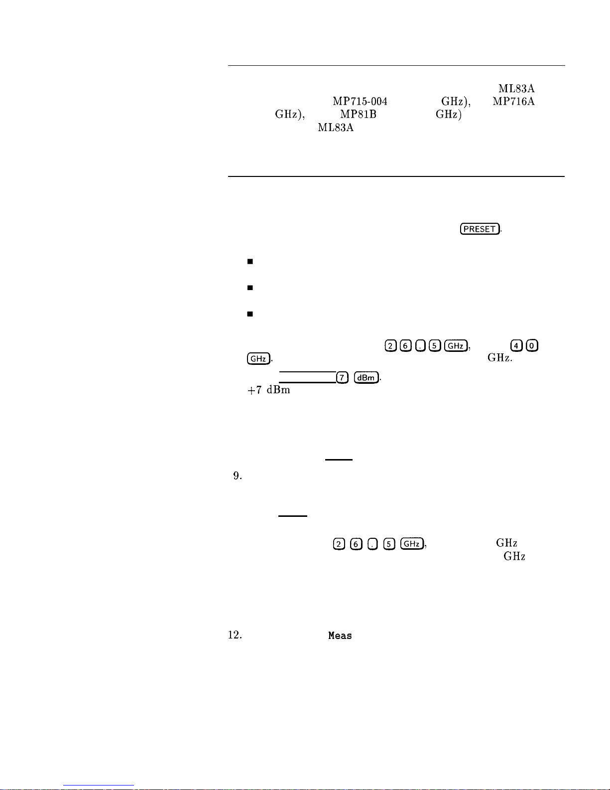
Note
U, V, and W-band power sensors are not available from
Hewlett-Packard. For these frequencies use the Anritsu ML83A
Power Meter with the MP715-004 (40 to 60 GHz), the MP716A
(50 to 75
GHz),
or the
MPSlB
(75 to 110 GHz) power sensors. Since
the Anritsu model ML83A Power Meter is not capable of internally
storing power sensor cal factors, you must manually correct the
data entry. Refer to example 2 for information on manual entry of
correction data.
Set up Swept CW Generator Parameters
5. Turn on the swept CW generator and press
(j).
The following occurs:
The source module’s frequency span is displayed on the swept
CW generator.
The swept CW generator’s leveling mode is automatically
changed from internal to “module leveling.”
The source module’s maximum specified power is set and
displayed.
6. Press FREQUENCY [START) @ @ 0 @
IGHz),
(STOP) @
@
IGHz).
The frequency sweep is set from 26.5 to 40 GHz.
7. Press (POWER LEVEL) 0
m.
The source module power is set to
+7 dBm
for maximum power to the device under test.
Access User Flatness Correction Menu
8. Press POWER (MENU). Select Fltness Menu.
9.
Select Delete Menu Delete All. This step insures that the
flatness array is empty.
10. Press (PRIOR). Leave the delete menu and return to the previous
soft key menu.
11. Select Enter Freq @ @ 0 @
(GHz),
to enter 26.5 GHz as
the first correction frequency. Enter 31, 32.5, and 40 GHz to
complete the list. Notice that the frequencies are arbitrarily
spaced.
Enter Correction Data into Array
12.
Select Mtr
Meas
Menu Measure Corr All . The power meter
is now under swept CW generator control and is performing
the sequence of steps necessary to generate the correction
information at each frequency point.
If an HP-IB error message is displayed verify that the interface
connections are correct. Check the HP-IB address of the power
meter and ensure that it is the same address the swept CW
Getting Started Advanced l-41
Page 68

generator is using (address 13 is assumed). Refer to the menu
map 8, System, for the key sequence necessary to reach softkey
Meter
Adrs
.
Enable User Flatness Correction
13. When the operation is complete, (a message is displayed) the
flatness correction array is ready to be applied to your setup.
14. To save the swept CW generator parameters including the
correction table in an internal register, press (SAVE)
0
(n = number 1 through 8).
15. Disconnect the power meter/sensor and press (FLTNESS ON/OFF)
(amber LED on). Thep
ower produced at the point where the
power meter/sensor was disconnected is now calibrated at the
frequencies and power level specified above.
1-42 Getting Started Advanced
Page 69
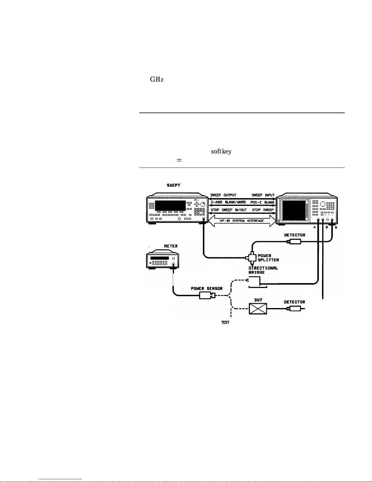
Scalar Analysis Measurement with User Flatness Corrections,
Example 4
The following example demonstrates how to set up a scalar analysis
measurement (using an HP 8757 Scalar Network Analyzer) of a 2 to
20 GHz test device such as, an amplifier. User flatness correction
is used to compensate for power variations at the test port of a
directional bridge. Follow the instructions to set up the swept CW
generator, then configure the system as shown in Figure 1-21.
Note
The swept CW generator’s rear panel language and address switches
must be set to 7 and 31 (all l’s), to change the language or address
of the swept CW generator from the front panel. The programming
language must be set to Analyzer. Refer to menu map 8, System,
to find the location of softkey Programming Language Analyzer
(asterisk on = active language).
-
m
RF OUT
POUER UETER
SUEPT
cu
SCRLRR
GENERATOR NETUORK RNRLYZER
I
,--JIKf’“““’
-‘-‘;,--ws&GR
J
EST ‘PORT
Figure l-21. Scalar System Configuration
Getting Started Advanced 1-43
Page 70

Example Overview
In this example, you use an HP 437B power meter to automatically
enter correction data into the array. It is necessary to turn off the
HP 8757 System Interface (controlled from the front-panel of the
analyzer) so that the swept CW generator can temporarily control
the power meter over HP-IB. When the correction data entry process
is complete, enable user flatness correction and set the desired
test port power level. Then store the correction table and swept
CW generator configuration in the same register that contains the
analyzer configuration. Re-activate the HP 8757 System Interface
and recall the stored register. Make sure that user flatness correction
is still enabled before making the measurement.
When an HP 437B power meter is used to automatically enter the
correction data, the correction calibration routine automatically turns
off any active modulation, then re-activates the modulation upon
the completion of the data entry process. Therefore, the scalar pulse
modulation that is automatically enabled in a scalar measurement
system is disabled during an HP 437B correction calibration.
Note
The user flatness correction array cannot be stored to a disk. You
must make sure that the array is stored in one of the eight internal
registers. Recalling a file from an HP 8757 disk will not erase the
current array; therefore you may recall an array from an internal
register, then recall an associated file from a disk.
For this example, refer to menu map 5, POWER.
1. The equipment setup shown in Figure 1-21 assumes that
you have followed the steps necessary to correctly level the
configuration. If you have questions about external leveling, refer
to “Externally Leveling the Swept CW Generator”.
2. On the analyzer, press [PRESET).
CW generator to a known state.
Reset the analyzer and swept
Set up System Parameters
3. On the swept CW generator, press FREQUENCY
LSTART) @
(GHz), -0
@
(GHzl.
Set the swept CW generator for a
frequency sweep of 2 to 20 GHz.
4. Press [POWER LEVEL) 0
(dBm).
Where n = maximum available
power.
5. On the analyzer, set up the appropriate measurement
(i.e. gain for an amplifier). Calibrate the measurement (thru and
short/open calibration). Press
ISAVE) 0
to store the analyzer’s
configuration and swept CW generator parameters in storage
register 1.
1-44 Getting Started Advanced
Page 71
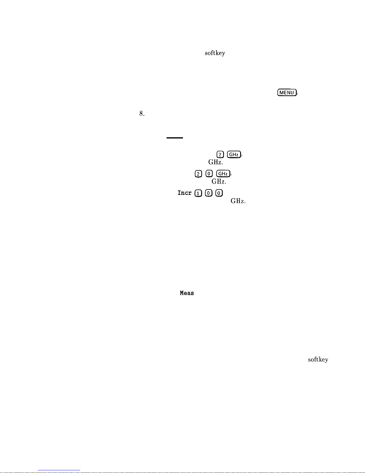
6. Turn off the HP 8757 System Interface. Use the analyzer
SYSINTF ON OFF
softkey
found under the SYSTEM menu to
deactivate the system interface.
Access User Flatness Correction Menu
7. On the swept CW generator, press POWER
[MENU).
Select
Fltness Menu.
8.
Select Delete Menu Delete All . This step insures that the
flatness array is empty.
9. Press (PRIOR). Leave the delete menu and return to the previous
soft key menu.
10. Select Auto Fill Start
(?J IGHz).
Set the first frequency in
correction table to 2 GHz.
11. Auto Fill Stop @ @
[GHz).
Set the last frequency in
correction table to 20 GHz.
12. Auto Fill
Incr @ @ @
(MHz. Set the frequency increment to
every 100 MHz from 2 to 20 GHz.
Set up Power Meter
13. Zero and calibrate the power meter/sensor.
14. Connect the power sensor to test port.
15. Enter and store in the power meter, the power sensor’s cal factors
for correction frequencies to be used.
Enter Correction Data into Array
16. Select Mtr
Meas
Menu Measure Corr All. The power meter
is now under swept CW generator control and is performing
the sequence of steps necessary to generate the correction
information at each frequency point.
If an HP-IB error message is displayed verify that the interface
connections are correct. Check the HP-IB address of the power
meter and ensure that it is the same address the swept CW
generator is using (address 13 is assumed). Refer to the menu
map 8, System, for the key sequence necessary to reach softkey
Meter Adrs .
Getting Started Advanced l-45
Page 72

Enable User Flatness Correction
17. When the operation is complete, (a message is displayed) the
flatness correction array is ready to be applied to your setup.
18. Disconnect the power meter/sensor.
19. On the swept CW generator, press [POWER LEVEL)
0 (dBm).
Where
n = PO max - Ppath
loss
for maximum leveled power at the test
port.
20. To save the swept CW generator parameters including the
correction table in an internal register, press (SAVE)
@
(n = number 1 through 8).
Reactivate the HP 8757 System Interface
21. Set the analyzer to SYSINTF ON, the analyzer and swept CW
generator preset.
22. Press (RECALL) 0. Recall the swept CW generator parameters
from storage register 1
23. On the swept CW generator, press (FLTNESS ON/OFF] (amber
LED on). The power produced at the point where the power
meter/sensor was disconnected is now calibrated at the
frequencies and power level specified above.
1-46 Getting Started Advanced
Page 73
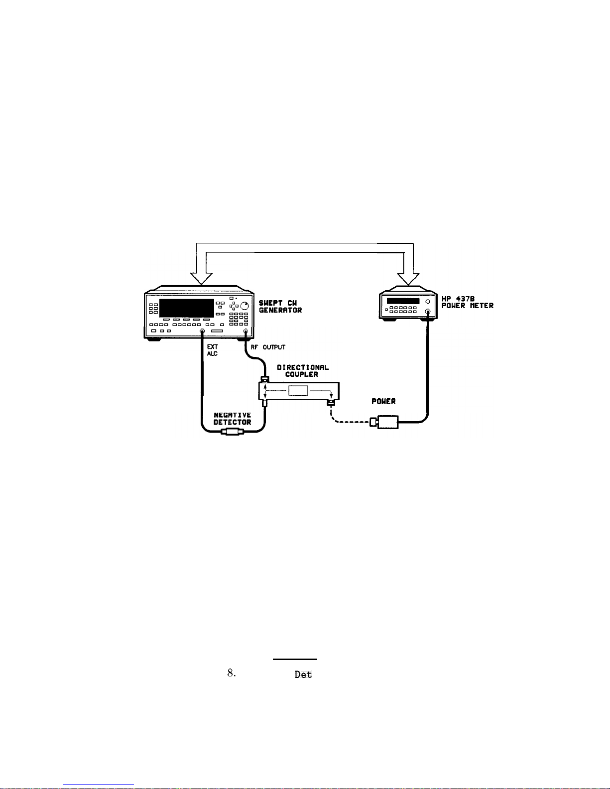
Using Detector
Detector calibration is useful for characterizing and compensating for
Calibration
negative diode detectors used in external leveling. Detectors may be
characterized by three operating regions as shown in Figure l-12:
the square law, the linear, and the transition region. The following
steps use an HP 437B to automatically characterize the operating
regions and use this information to automatically compensate for
the detector being used. The equipment setup shown in Figure 1-22
assumes that the steps necessary to correctly externally level have
been followed.
Refer to menu map 9, USER CAL.
HP-16
/&]
:Kz.iR
POUER
SENSOR
Figure l-22. Automatically Characterizing and Compensating for a Detector
1. Connect the power meter as shown.
2. Zero and calibrate the power meter/sensor.
3. Enter the appropriate power sensor calibration factors into the
power meter.
4. Enable the power meter/sensor cal factor array. For operating
information on the HP 437B power meter, refer to its operating
and service manual.
5. Connect the power sensor to the output of the coupler
(or splitter).
6. On the swept CW generator, set the power level and start/stop
frequency information as desired.
7. Press (USER).
8.
Select Ext
Det
Cal . The power meter is now under swept
CW generator control and is performing the sequence of steps
necessary to generate the compensation information.
Getting Started Advanced 1-47
Page 74

If an HP-IB error message is displayed verify that the interface
connections are correct. Check the HP-IB address of the power
meter and ensure that it is the same address the swept CW
generator is using (address 13 is assumed). Refer to the menu
map 8, System, for the key sequence necessary to reach softkey
Meter Adrs.
9. When the operation is complete, (a message is displayed)
disconnect the power meter/sensor. The swept CW generator has
stored the compensation information in its memory and is using it
to calibrate the detector’s output voltage relative to power.
1-48 Getting Started Advanced
Page 75

Using the Tracking
Feature
Peaking
Peaking is the function that aligns the output filter (YTM) so that
its
passband
is centered on the RF output, in CW or manual-sweep
mode. Use peaking to obtain the maximum available power and
spectral purity, and best pulse envelopes, at any given frequency
above 2.0 GHz. The YTM is inactive for the low band frequencies
(10 MHz to 2.0 GHz).
To peak at the present CW frequency:
Press
(USER).
Select Tracking Menu Peak RF Once.
This causes an instantaneous execution of the peaking function. This
is a one-time implementation of the peaking, where the function is
turned on and then turned off.
To peak at the present CW frequency, and continue to peak at new
frequencies as they are entered:
Press
(USER).
Select Tracking Menu Peak RF Always.
If “peak always” is on (denoted by an asterisk next to the key
label) for an extended period of time, the peaking function will
automatically repeak every seven minutes.
Tracking
Auto track is a more extensive version of peaking. It causes all of
the YTM tracking calibration constants to be aligned and requires
approximately 40 to 90 seconds to complete. Tracking is performed
from 2.0 GHz to the end of the specified frequency range.
Note
If the swept CW generator does not have a step attenuator,
terminate the RF OUTPUT with a good
500
impedance match such
as a 10 dB attenuator or a power sensor to prevent mistracking.
To enhance the power output and spectral purity of swept
modes, and to improve tracking performance (especially in harsh
environments having wide temperature variations):
Press (USER).
Select Tracking Menu Auto Track.
Getting Started Advanced 1-49
Page 76

ALC Bandwidth
Selection
The ALC bandwidth defaults at factory preset to the auto selection
ALC Bandwidth Select Auto
which selects the appropriate
bandwidth [high or low) for each application. To make the
bandwidth
sel&tion,
thk swept CW generator determines which
functions are activated and uses the decision tree shown in
Figure l-23.
High
Bw
Low’
Ew
NO
Smrch?
-or-
uat
0
F~UNlcy?
-or-
SOP
sweep?
NO
Low
Bw
=-b High BW
Figure l-23. Decision Tree for ALC Bandwidth Selection
l-50 Getting Started Advanced
Page 77

Using Step Sweep
1. Refer to menu map 2.
2. Press FREQUENCY [MENU).
3. Select
Step Swp Menu.
4.
Select
Step Size.
Enter the desired increment value.
5.
Select Step Points . Enter the number of points desired.
6.
Determine the dwell time desired, select Step Dwell and enter
a value, or choose the dwell time determined by the ramp mode
sweep time, select
Dwell Coupled.
7.
Determine the triggering scheme, select
Step Swp Pt Trig Auto ,
Bus,or
Ext.
8. Press SWEEP (MENU_).
9.
Select Sweep Mode Step, to activate the step frequency mode.
Getting Started Advanced 1-51
Page 78

Creating and Using
a Frequency List
1. Refer to menu map 2.
2. Press FREQUENCY
(MENU).
3.
Select List Menu.
To use the frequency points of a frequency list to create the
frequency portion of the user flatness correction array:
1. Refer to menu map 5.
2. Press POWER
(=I.
3.
Select
Fitness
Menu.
4.
Select Copy List .
1-52 Getting Started Advanced
Page 79

Using the Security
To access the security menu:
Features
1. Refer to menu map 8.
2. Press SYSTEM
(MENU).
3.
Select Security Menu.
Getting Started Advanced
l-53
Page 80
Changing the Preset
1. Set up the swept CW generator in the desired operation state to
Parameters
be used as the preset state.
2. Refer to menu map 8.
3. Press SYSTEM (MENU).
4.
Select Save User Preset .
5.
Select Preset Mode User.
Whenever the
(w]
key is pressed, the swept CW generator will
return to the operation state setup and saved in steps 1 and 4. The
swept CW generator displays:
***
USERDEFINEDPRESETRECALLED ***
and also gives you the option of selecting the factory preset state by
creating a factory preset softkey.
1-54 Getting Started Advanced
Page 81

Programming
Getting Started
Programming
HP-IB, the Hewlett-Packard Interface Bus, is the
instrument-to-
instrument communication system between the swept CW generator
and up to 14 other instruments. Any instrument having HP-IB
capability can be interfaced to the swept CW generator, including
non-HP instruments that have “GPIB,” “IEEE-488,” “ANSI
MC1.l,” or “IEC-625” capability (these are common generic terms
for HP-IB; all are electrically equivalent although IEC-625 uses a
unique connector). This portion of the manual specifically describes
interfacing the swept CW generator to one type of instrument: a
computer.
The first part of this section provides general HP-IB information.
Later, the Standard Commands for Programmable Instruments
language (SCPI)
is introduced, and example programs are given.
For information on programming in the Control Interface
Intermediate Language (CIIL),
refer to a separate option 700 manual
supplement.
Modulation Commands
When programming commands relating to modulation are sent to the
HP 8360 L-Series swept CW generator, the commands are parsed
but no action is taken on the command. Also, no error message is
generated.
Getting Started Programming l-55
Page 82

HP-IB General
Information
Interconnecting Cables
Instrument Addresses
HP-18
Instrument
Nomenclature
Programming the Swept
CW Generator
l-58 Getting Started Programming
Figure C-2 shows the swept CW generator rear-panel HP-IB
connector and suitable cables, and describes the procedures and
limitations for interconnecting instruments. Cable length restrictions,
also described in Figure C-2, must be observed.
Each instrument in an HP-IB network must have a unique address,
ranging in value from 00-30 (d
ecimal).
The default address for
the swept CW generator is 19, but this can be changed using the
My Adrs softkey or rear panel switch as described in the reference
chapter (Chapter 2) under the “8360 Adrs” entry (the examples
in this section use 19 as the address for the swept CW generator).
Other instruments use a variety of procedures for setting the address,
as described in their operating manuals, but typically either a rear
panel switch or a front panel code is used.
An HP-IB instrument is categorized as a “listener,” “talker,” or
“controller,”
depending on its current function in the network.
Listener
A listener is a device capable of receiving data or commands from
other instruments. Any number of instruments in the HP-IB network
can be listeners simultaneously.
Talker
A talker is a device capable of transmitting data or commands to
other instruments. To avoid confusion, an HP-IB system allows only
one device at a time to be an active talker.
Controller
A controller is an instrument, typically a computer, capable of
managing the various HP-IB activities. Only one device at a time
can be an active controller.
The swept CW generator can be controlled entirely by a computer
(although the line POWER switch must be operated manually).
Several functions are possible only by computer (remote) control.
Computer programming procedures for the swept CW generator
involve selecting an HP-IB command statement, then adding the
specific swept CW generator (SCPI, Analyzer, or CIIL) programming
codes to that statement to achieve the desired operating conditions.
The programming codes can be categorized into two groups: those
that mimic front panel keystrokes; and those that are unique, and
have no front panel equivalent.
Page 83

In the programming explanations that follow, specific examples are
included that are written in a generic dialect of the BASIC language.
BASIC was selected because the majority of HP-IB computers have
BASIC language capability. However, other languages can also be
used.
HP-IB Command
Command statements form the nucleus of HP-IB programming;
Statements
they are understood by all instruments in the network and, when
combined with the programming language codes, they provide all
management and data communication instructions for the system.
An explanation of the fundamental command statements follows.
However, some computers use a slightly different terminology,
or support an extended or enhanced version of these commands.
Consider the following explanations as a starting point, but
for detailed information consult the BASIC language reference
manual, the I/O programming guide, and the HP-IB manual for the
particular computer used.
Syntax drawings accompany each statement: All items enclosed by
a circle or oval are computer specific terms that must be entered
exactly as described; items enclosed in a rectangular box are names
of parameters used in the statement; and the arrows indicate a path
that generates a valid combination of statement elements.
The seven fundamental command statements are as follows:
Abort
Abort abruptly terminates all listener/talker activity on the interface
bus, and prepares all instruments to receive a new command from the
controller. Typically, this is an initialization command used to place
the bus in a known starting condition. The syntax is:
interface
select
h
code
where the interface select code is the computer’s HP-IB I/O port,
which is typically port 7. Some BASIC examples:
10
ABORT7
100
IF
V>20
THEN ABORT 7
Related statements used by some computers:
ABORT10 (used by HP-80 series computers)
HALT
RESET
Getting Started Programming 1-57
Page 84

Remote
Remote causes an instrument to change from local control to
remote control. In remote control, the front panel keys are disabled
(except for the
(LOCAL)
key and the POWER switch), and the amber
REMOTE annunciator is lighted. The syntax is:
where the device selector is the address of the instrument appended
to the HP-IB port number. Typically, the HP-IB port number is 7,
and the default address for the swept CW generator is 19, so the
device selector is 719. Some BASIC examples:
10
REMOTE 7
which prepares all HP-IB instruments for remote operation (although
nothing appears to happen to the instruments until they are
addressed to talk), or
10
REMOTE 719
which affects the HP-IB instrument located at address 19, or
10
REMOTE719, 721, 726,
715
which
effects four instruments
that
have addresses
19,
21, 26,
and
15.
Related statements used by some computers:
RESUME
Local Lockout
Local Lockout can be used in conjunction with REMOTE to disable
the front panel (LOCAL) key. With the (LOCAL) key disabled, only the
controller (or a hard reset by the POWER switch) can restore local
control. The syntax is:
interface
select
w
code
A BASIC example:
10
REMOTE719
20
LOCAL LOCKOUT 7
1-58 Getting Started Programming
Page 85
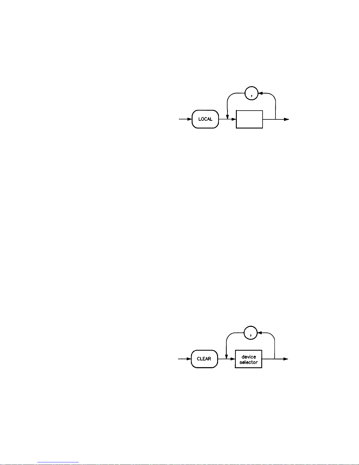
Local
Local is the complement to
return to local control with
is:
REMOTE, causing an instrument to
a fully enabled front panel. The syntax
device
selector
Some BASIC examples:
10
LOCAL 7
which effects all instruments in the network, or
10
LOCAL 719
for an addressed instrument (address 19).
Related statements used by some computers:
RESUME
Clear
Clear causes all HP-IB instruments, or addressed instruments, to
assume a “cleared” condition, with the definition of “cleared” being
unique for each device. For the swept CW generator:
1. All pending output-parameter operations are halted.
2. The parser (the software that interprets the programming codes)
is reset, and now expects to receive the first character of a
programming code.
The syntax is:
Getting Started Programming 1-59
Page 86

Some BASIC examples:
10
CLEAR 7
to clear all HP-IB instruments, or
10
CLEAR 719
to clear an addressed instrument.
Related statements used by some computers:
RESET
CONTROL
SEND
The preceding statements are primarily management commands
that do not incorporate programming codes. The following two
statements do incorporate programming codes, and are used for data
communication.
Output is used to send function commands and data commands from
the controller to the addressed instrument. The syntax is:
where USING is a secondary command that formats the output in a
particular way, such as a binary or ASCII representation of numbers.
The USING command is followed by “image items” that precisely
define the format of the output; these image items can be a string of
code characters, or a reference to a statement line in the computer
program. Image items are explained in the programming codes where
they are needed. Notice that this syntax is virtually identical to the
syntax for the ENTER statement that follows.
l-60 Getting Started Programming
Page 87
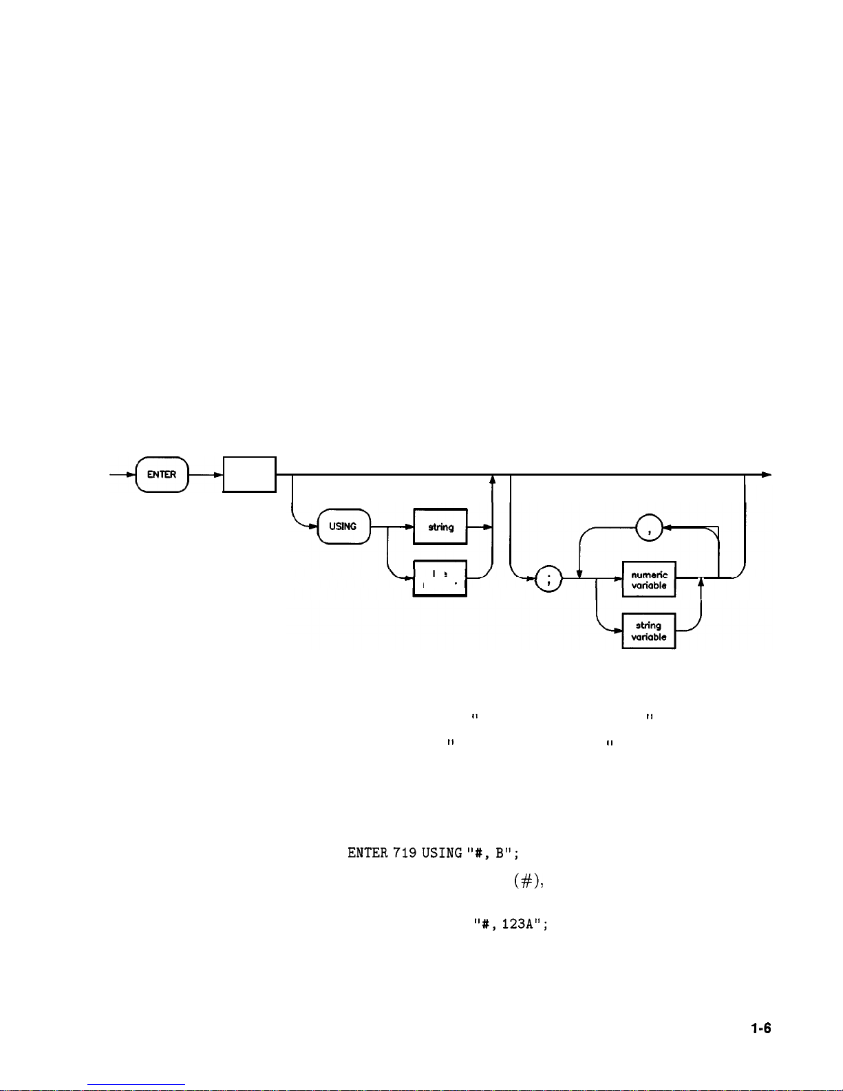
A BASIC example:
100 OUTPUT719;
“programming codes”
The many programming codes for the swept CW generator are listed
in the “SCPI Command Summary” in Chapter 2.
Related statements used by some computers:
CONTROL
CONVERT
IMAGE
IOBUFFER
TRANSFER
Enter
Enter is the complement of OUTPUT, and is used to transfer data
from the addressed instrument to the controller. The syntax is:
devicedevice
selectorselector
A
t
I
A
-
line
number
t
ENTER is always used in conjunction with OUTPUT, such as:
100
OUTPUT 719;
”
. . . programming codes . . .
‘I
110
ENTER719;
‘I
. . . response
data...
'I
ENTER statements are commonly formatted, which requires the
secondary command USING and the appropriate image items. The
most-used image items involve end-of-line (EOL) suppression, binary
inputs, and literal inputs. For example:
100 ENTER719USING
"#,B";
A, B, C
suppresses the EOL sequence
(#),
and indicates that variables A, B,
and C are to be filled with binary (B) data. As another example,
100 ENTER719 USING
"t, 123A";
A$
suppresses EOL, and indicates that string variable A$ is to be filled
with 123 bytes of literal data (123A).
Getting Started Programming
l-6
1
Page 88

Note
Be careful when using byte-counting image specifiers. If the
requested number of bytes does not match the actual number
available, data might be lost, or the program might enter an endless
wait state.
The suppression of the EOL sequence is frequently necessary to
prevent a premature termination of the data input. When not
specified, the typical EOL termination occurs when an ASCII LF
(line feed) is received. However, the LF bit pattern could
coincidentally occur randomly in a long string of binary data, where
it might cause a false termination. Also, the bit patterns for the
ASCII CR (carriage return), comma, or semicolon might cause a false
termination. Suppression of the EOL causes the computer to accept
all bit patterns as data, not commands, and relies on the HP-IB EOI
(end or identify) line for correct end-of-data termination.
Related statements used by some computers:
CONVERT
IMAGE
IOBUFFER
ON TIMEOUT
SET TIMEOUT
TRANSFER
This completes the HP-IB Command Statements subsection. The
following material explains the SCPI programming codes, and shows
how they are used with the OUTPUT and ENTER HP-IB command
statements.
1-62 Getting Started Programming
Page 89

Getting Started with
This section of Chapter 1 describes the use of the Standard
SCPI
Commands for Programmable Instruments language (SCPI). This
section explains how to use SCPI commands in general. The
instrument command summary (at the end of this chapter) lists
the specific commands available in your instrument. This section
presents only the basics of SCPI. If you want to explore the topic in
greater depth, see the paragraph titled, “Related Documents.”
Definitions of Terms
This section defines most terms when they are first used, you need a
general understanding of the terms listed below before you continue.
controller
instrument
program
message
response
message
command
query
A controller is any computer used to communicate
with a SCPI instrument. A controller can be a
personal computer, a minicomputer, or a plug-in card
in a card cage. Some intelligent instruments can also
function as controllers.
An instrument is any device that implements SCPI.
Most instruments are electronic measurement or
stimulus devices, but this is not a requirement.
Similarly, most instruments use an HP-IB interface
for communication. The same concepts apply
regardless of the instrument function or the type of
interface used.
A program message is a combination of one
or more properly formatted SCPI commands.
Program messages always go from a controller to an
instrument. Program messages tell the instrument
how to make measurements and output signals.
A response message is a collection of data in specific
SCPI formats. Response messages always go from an
instrument to a controller or listening instrument.
Response messages tell the controller about the
internal state of the instrument and about measured
values.
A command is an instruction in SCPI. You
combine commands to form messages that control
instruments. In general, a command consists of
mnemonics (keywords), parameters, and punctuation.
A query is a special type of command. Queries
instruct the instrument to make response data
available to the controller. Query mnemonics always
end with a question mark.
Getting Started Programming 1-63
Page 90

Standard Notation
This section uses several forms of notation that have specific
meaning.
Command Mnemonics
Many commands have both a long and a short form, and you must
use either one or the other (SCPI does not accept a combination
of the two). Consider the FREQuency command, for example. The
short form is FREQ and the long form is FREQUENCY (this notation
style is a shorthand to document both the long and short form of
commands). SCPI is not case sensitive, so
fREquEnCy
is just as valid
as FREQUENCY, but FREQ and FREQUENCY are the only valid forms of
the FREQuency command.
Angle Brackets
Angle brackets indicate that the word or words enclosed represent
something other than themselves. For example, <new line>
represents the ASCII character with the decimal value 10. Similarly,
<-END>means
that EOI is asserted on the HP-IB interface. Words
in angle brackets have much more rigidly defined meaning than
words used in ordinary text. For example, this section uses the word
“message” to talk about messages generally. But the bracketed words
<program message> indicate a precisely defined element of SCPI.
If you need them, you can find the exact definitions of words such as
<program message> in a syntax diagram.
How to Use Examples
It is important to understand that programming with SCPI
actually requires knowledge of two languages. You must know
the programming language of your controller (BASIC, C, Pascal)
as well as the language of your instrument (SCPI). The semantic
requirements of your controller’s language determine how the SCPI
commands and responses are handled in your application.
Command Examples
Command examples look like this:
:FREQuency:CW?
This example tells you to put the string : FREQuency : CW? in the
output statement appropriate to your application programming
language. If you encounter problems, study the details of how the
output statement handles message terminators such as
<new
line>.
If you are using simple OUTPUT statements in HP BASIC, this is
taken care of for you. In HP BASIC, you type:
OUTPUT Source ; ” : FREQuency :
CW?”
Command examples do not show message terminators because
they are used at the end of every program message. “Details of
1-64 Getting Started Programming
Page 91

Commands and Responses,”
discusses message terminators in more
detail.
Response Examples
Response examples look like this:
1.23
These are the characters you would read from an instrument
after sending a query command. To actually pull them from the
instrument into the controller, use the input statement appropriate
to your application programming language. If you have problems,
study the details of how the input statement operates. In particular,
investigate how the input statement handles punctuation characters
such as comma and semicolon, and how it handles <new
line>
and
EOL.
To enter the previous response in HP BASIC, you type:
ENTER
Source;CW-frequency
Response examples do not show response message terminators
because they are always <new line>
<-END>.
These terminators
are typically automatically handled by the input statement. The
paragraph titled “Details of Commands and Responses” discusses
message terminators in more detail.
Getting Started Programming 1-65
Page 92

Essentials for
Beginners
This subsection discusses elementary concepts critical to first-time
users of SCPI. Read and understand this subsection before going on
to another. This subsection includes the following topics:
Program and Response
Messages
These paragraphs introduce the
basic types of messages sent between
instruments and controllers.
Subsystem Command Trees
Subsystem Command Tables
Reading Instrument Errors
Example Programs
These paragraphs describe the
tree structure used in subsystem
commands.
These paragraphs present the
condensed tabular format used for
documenting subsystem commands.
These paragraphs explain how to read
and print an instrument’s internal
error messages.
These paragraphs contain two simple
measurement programs that illustrate
basic SCPI programming principles.
Program and Response
To understand how your instrument and controller communicate
Messages
using SCPI, you must understand the concepts of program and
response messages. Program messages are the formatted data sent
from the controller to the instrument. Conversely, response messages
are the formatted data sent from the instrument to the controller.
Program messages contain one or more commands, and response
messages contain one or more responses.
The controller may send commands at any time, but the instrument
sends responses only when specifically instructed to do so. The
special type of command used to instruct the instrument to send
a response message is the query. All query mnemonics end with a
question mark. Queries return either measured values or internal
instrument settings. Any internal setting that can be programmed
with SCPI can also be queried.
Forgiving Listening and Precise Talking
SCPI uses the concept of forgiving listening and precise talking
outlined in IEEE 488.2. Forgiving listening means that instruments
are very flexible in accepting various command and parameter
formats. For example, the swept CW generator accepts either
: POWer : STATe ON or : POWer : STATe 1 to turn RF output on. Precise
talking means that the response format for a particular query is
always the same. For example, if you query the power state when it
is on (using :POWer:STATe?), the response is always 1, regardless of
whether you previously sent
:POWer
: STATe 1 or : POWer : STATe ON.
1-66 Getting Started Programming
Page 93

Types of Commands
Commands can be separated into two groups, common commands
and subsystem commands. Common commands are generally not
measurement related. They are used to manage macros, status
registers, synchronization, and data storage. Common commands
are easy to recognize because they all begin with an asterisk,
such as *IDN?,
*OPC,
and *RST. Common commands are defined
by IEEE 488.2. Subsystem commands include all measurement
functions and some general purpose functions. Subsystem commands
are distinguished by the colon used between keywords, as in
:
FREQuency
:CW?. Each command subsystem is a set of commands
that roughly corresponds to a functional block inside the instrument.
For example, the
POWer
subsystem contains commands for power
generation, while the STATUS subsystem contains commands for
accessing status registers.
l-l
SPCI
Common
Commands
“FIST
*IDN?
Subsystem
Commands
:MEAS:VOLT?
:FREQ 1KHz
Do75b
Figure l-24.
SCPI
Command Types
The remaining paragraphs in this subsection discuss subsystem
commands in more detail. Remember, some commands are
implemented in one instrument and not in another, depending on its
measurement function.
Getting Started Programming 1-67
Page 94

Subsystem Command
Trees
The Command Tree Structure
Most programming tasks involve subsystem commands. SCPI uses
a hierarchical structure for subsystem commands similar to the file
systems on most computers. In SCPI, this command structure is
called a command tree.
root
AA
level 1
I I
BB
cc
DD
rtl
rtl
level 2 EE FF GG
HH
Figure l-25. A Simplified Command Tree
JJ
In the command tree shown in Figure l-25, the command closest to
the top is the root command, or simply the root. Notice that you
must follow a particular
path
to reach lower level subcommands. For
example, if you wish to access the GG command, you must follow the
path
AA
to
BB
to
GG.
Paths Through the Command Tree
To access commands in different paths in the command tree, you
must understand how an instrument interprets commands. A special
part of the instrument firmware, a parser, decodes each message sent
to the instrument. The parser breaks up the message into component
commands using a set of rules to determine the command tree path
used. The parser keeps track of the current path, the level in the
command tree where it expects to find the next command you send.
This is important because the same keyword may appear in different
paths. The particular path you use determines how the keyword is
interpreted. The following rules are used by the parser:
w
Power On and Reset
After power is cycled or after
*RST,
the current path is set to the
root.
n Message Terminators
A message terminator, such as a <new line> character, sets the
current path to the root. Many programming languages have
output statements that send message terminators automatically.
The paragraph titled,
“Details of Commands and Responses,”
discusses message terminators in more detail.
1-68 Getting Started Programming
Page 95

n
Colon
When it is between two command mnemonics, a colon moves the
current path down one level in the command tree. For example,
the colon in
MEAS:VOLT
specifies that VOLT is one level below
MEAS.
When the colon is the first character of a command, it specifies
that the next command mnemonic is a root level command. For
example, the colon in : INIT specifies that
INIT
is a root level
command.
w
Semicolon
A semicolon separates two commands in the same message without
changing the current path.
w
Whitespace
White space characters, such as <tab> and
<space>,
are generally
ignored. There are two important exceptions. White space inside a
keyword, such as :FREQ uency, is not allowed. You must use white
space to separate parameters from commands. For example, the
<space> between LEVel and 6.2 in the command
:
POWer
: LEVel 6.2 is mandatory. White space does not affect the
current path.
w
Commas
If a command requires more than one parameter, you must
separate adjacent parameters using a comma. Commas do not
affect the current path.
w
Common Commands
Common commands, such as
*RST,
are not part of any subsystem.
An instrument interprets them in the same way, regardless of the
current path setting.
Figure l-26 shows examples of how to use the colon and semicolon to
navigate efficiently through the command tree.
Getting Started Programming 1-69
Page 96
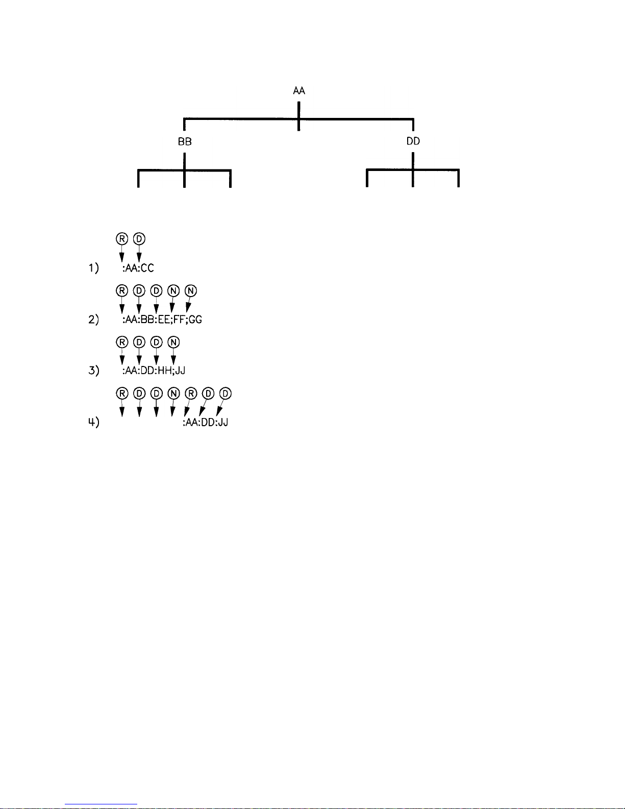
1)
2)
3)
4)
;
r-L
cc
r-L
EE
FF
GG
HH
R
D
??
0
R
:&KC
vu??
0
N
:M:BB:EE;FF;GG
WV
0
D
:AA:DD:HH;JJ
~~WfT
:AA:BB:EE;
:M:DD:JJ
JJ
Sets current path
to ROOT
NO change to
current path
Set current path
DOWN one level
Figure l-26. Proper Use of the Colon and Semicolon
In Figure l-26, notice how proper use of the semicolon can save
typing.
Sending this message:
:AA:BB:EE; FF; GG
Is the same as sending these three messages:
:AA:BB:EE
:AA:BB:FF
:AA:BB:GG
l-70 Getting Started Programming
Page 97
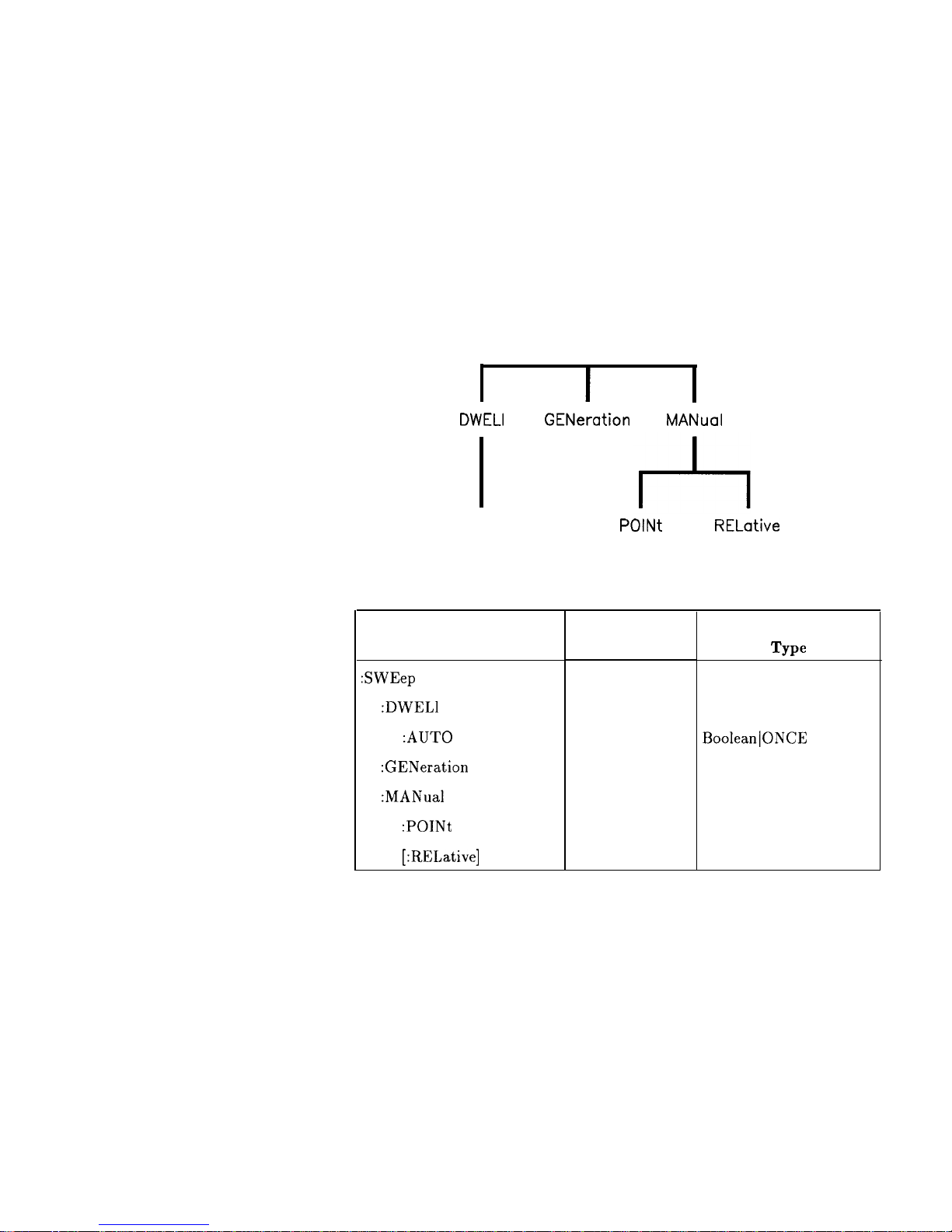
Subsystem Command
These paragraphs introduce a more complete, compact way of
Tables
documenting subsystems using a tabular format. The command
table contains more information than just the command hierarchy
shown in a graphical tree. In particular, these tables list command
parameters for each command and response data formats for queries.
To begin this exploration of command tables, consider a simplified
SWEep subsystem for the swept CW generator in both the graphical
and tabular formats.
SWEep
I
DWELI
GENeration
MANuaI
AUTO
POlNt
RELative
Figure l-27. Simplified SWEep Command Tree
Table 1-2. SWEep Command Table
Command
:SWEep
:DWELl
:AUTO
:GENeration
:MANual
:POINt
[:RELative]
Parameters
state
Parameter
Type
BooleanlONCE
Reading the Command Table
Note the three columns in the command table labeled Command,
Parameters, and Parameter Type. Commands closest to the root
level are at the top of the table. Commands in square brackets
are implied commands, which are discussed in later paragraphs.
If a command requires one or more parameters in addition to the
keyword, the parameter names are listed adjacent to the command.
Parameters in square brackets are optional parameters, which are
discussed in later paragraphs. If the parameter is not in square
brackets, it is required and you must send a valid setting for it with
Getting Started Programming 1-71
Page 98

the matching command. The parameter type is listed adjacent to
each named parameter.
More About Commands
Query and Event Commands. Because you can query any value that
you can set, the query form of each command is not shown explicitly
in the command tables. For example, the presence of the swept CW
generator : SWEep :
DWELl
command implies that a : SWEep :
DWELl?
also exists. If you see a table containing a command ending with
a question mark, it is a query only command. Some commands
are
ewents,
and cannot be queried. An event has no corresponding
setting if it causes something to happen inside the instrument at a
particular instant. For example,
:
INITiate:
IMMediate causes a
certain trigger sequence to initiate. Because it is an event, there is no
query form of :
INITiate
:
IMMediate.
Implied Commands. Implied commands appear in square brackets
in the command table. If you send a subcommand immediately
preceding an implied command, but do not send the implied
command, the instrument assumes you intend to use the implied
command, and behaves just as if you had sent it. Note that this
means the instrument expects you to include any parameters
required by the implied command. The following example illustrates
equivalent ways to program the swept CW generator using explicit
and implied commands.
Example swept CW generator commands with and without an
implied commands:
: SWEep :
MANual
: RELat ive 6
using explicit commands
:SWEep:MANual
6 using implied commands
Optional Parameters. Optional parameter names are enclosed in
square brackets in the command table. If you do not send a value
for an optional parameter, the instrument chooses a default value.
The instrument’s command dictionary documents the values used for
optional parameters.
Program Message Examples
The following parts of the swept CW generator SCPI command set
will be used to demonstrate how to create complete SCPI program
messages:
:FREQuency
[:CWl
:MULTiplier
: STATE
: POWER
[
: LEVEL]
1-72 Getting Started Programming
Page 99
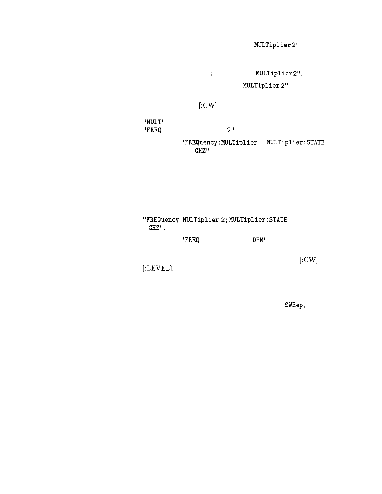
Example 1:
“FREQuency : CW 5 GHZ ;
MULTiplier
2”
The command is correct and will not cause errors. It is equivalent to
sending:
“FREQuency : CW 5 GHZ ;: FREQuency :
MULTiplier 2”.
Example 2: “FREQuency 5 GHZ;
MULTiplier 2”
This command results in a command error. The command makes
use of the default
[:CW]
node. When using a default node, there is
no change to the current path position. Since there is no command
“MULT”
at the root, an error results. A correct way to send this is:
“FREQ
5 GHZ; FREQ :MULT 2” or as in example 1.
Example 3:
“FREQuency:MULTiplier
2; MULTiplier:STATE ON;
FREQuency : CW 5
GHZ”
This command results in a command error. The FREQ:CW portion
of the command is missing a leading colon. The path level is dropped
at each colon until it is in the FREQ:MULT subsystem. So when the
FREQ:CW command is sent, it causes confusion because no such
node occurs in the FREQ:MULT subsystem. By adding a leading
colon, the current path is reset to the root. The corrected command
is:
“FREQuency:MULTiplier2;
MULTiplier:STATE ON; :FREQuency:CW
5
GHZ”.
Example 4:
“FREQ
5 GHZ; POWER 4
DBM”
Notice that in this example the keyword short form is used. The
command is correct. It utilizes the default nodes of
[:CW]
and
[:LEVEL]. Since default nodes do not affect the current path, it is
not necessary to use a leading colon before POWER.
Parameter Types
As you saw in the example command table for
SWEep,
there are
several types of parameters. The parameter type indicates what
kind of values are valid instrument settings. The most commonly
used parameter types are numeric, extended numeric, discrete, and
Boolean. These common types are discussed briefly in the following
paragraphs. The paragraph titled “Details of Commands and
Responses” explains all parameter types in greater depth.
Numeric Parameters. Numeric parameters are used in both
subsystem commands and common commands. Numeric parameters
accept all commonly used decimal representations of numbers
including optional signs, decimal points, and scientific notation. If an
instrument accepts only specific numeric values, such as integers, it
automatically rounds numeric parameters to fit its needs.
Getting Started Programming 1-73
Page 100

Examples of numeric parameters:
100
no decimal point required
100.
fractional digits optional
-1.23
leading signs allowed
4.56e<space>3
space allowed after e in exponents
-7.89E-01
use either E or e in exponentials
+256
leading + allowed
.5
digits left of decimal point optional
Examples of numeric parameters in commands:
100 OUTPUT @Source;":
FREQuency:STARt
l.OE+09"
110 OUTPUT @Source;":
LIST:FREQuency
lO.Oe+9,le+7"
Extended Numeric Parameters.
Most measurement
related
subsystems use extended numeric parameters to specify physical
quantities. Extended numeric parameters accept all numeric
parameter values and other special values as well. All extended
numeric parameters accept
MAXimum
and
MINimum
as values. Other
special values, such as Up and DOWN may be available as documented
in the instrument’s command summary. Some instruments also
let you to send engineering units as suffixes to extended numeric
parameters. The SCPI Command Summary lists the suffixes
available, if any. Note that extended numeric parameters are not
used for common commands or
STATUS subsystem commands.
Examples of extended numeric parameters:
100.
any simple numeric values
-1.23
largest valid setting
4.56e<space>3
-7.89E-01
+256
.5
MAX
MIN
valid setting nearest negative infinity
Examples of extended numeric parameters in commands:
100 OUTPUT
OSource;":FREQuency:STOP
MAX"
110 OUTPUT
QSource;":LIST:FREQuency
MAX,MIN"
1-74 Getting Started Programming
 Loading...