

Page 1

HP 830 24-Port PoE+ Unified Wired-WLAN
Switch
Installation Guide
Part number:
5998-3900
Document version: 6W100-20130318
Page 2

Legal and notice information
© Copyright 2013 Hewlett-Packard Development Company, L.P.
No part of this documentation may be reproduced or transmitted in any form or by any means without
prior written consent of Hewlett-Packard Development Company, L.P.
The information contained herein is subject to change without notice.
HEWLETT-PACKARD COMPANY MAKES NO WARRANTY OF ANY KIND WITH REGARD TO THIS
MATERIAL, INCLUDING, BUT NOT LIMITED TO, THE IMPLIED WARRANTIES OF MERCHANTABILITY
AND FITNESS FOR A PARTICULAR PURPOSE. Hewlett-Packard shall not be liable for errors contained
herein or for incidental or consequential damages in connection with the furnishing, performance, or
use of this material.
The only warranties for HP products and services are set forth in the express warranty statements
accompanying such products and services. Nothing herein should be construed as constituting an
additional warranty. HP shall not be liable for technical or editorial errors or omissions contained
herein.
Page 3

i
Contents
Preparing for installation ············································································································································· 1
Safety recommendations ·················································································································································· 1
Safety symbols ·························································································································································· 1
General safety recommendations ··························································································································· 1
Electrical safety ························································································································································· 2
Laser safety ································································································································································ 2
Examining the installation site ········································································································································· 2
Temperature and humidity…. ································································································································· 2
Cleanness ·································································································································································· 3
Power ········································································································································································· 3
Cooling ······································································································································································ 3
ESD prevention ························································································································································· 4
EMI ············································································································································································· 5
Lightning protection ·················································································································································· 5
Accessories ········································································································································································ 5
Installation preparation checklist ····································································································································· 6
Installing the switch ······················································································································································ 8
Confirming installation preparations ······························································································································· 8
Installation flow ································································································································································· 9
Mounting the switch on a workbench ····························································································································· 9
Installing the switch in a 19-inch rack ·························································································································· 10
Mounting brackets ················································································································································· 10
Slide rails ································································································································································ 11
Installing the switch by using front and rear mounting brackets ······································································ 11
Installing the switch by using front mounting brackets and a rack shelf ························································· 14
Installing the switch by using front mounting brackets and slide rails ····························································· 15
Grounding the switch ···················································································································································· 17
Grounding the switch with a grounding strip (recommended ·········································································· 17
Grounding the switch with a grounding conductor buried in the earth ·························································· 18
Grounding the switch through the PE wire of an AC power cord ··································································· 18
Installing a lightning protector for a network port (optional) ····················································································· 19
Installation procedures ·········································································································································· 19
Precautions ····························································································································································· 20
Connecting the AC power supply to a power strip with lightning protection ························································· 20
Connecting the interface cables ··································································································································· 21
Connecting the console cable ······························································································································ 21
Setting terminal parameters ·································································································································· 21
Connecting the Ethernet cables ··························································································································· 24
Installing and removing an HP 830 uplink module) ··································································································· 25
Installing an HP 830 uplink module ···················································································································· 26
Removing an HP 830 uplink module ·················································································································· 27
Connecting the power cord ·········································································································································· 27
Connecting an AC power cord ··························································································································· 27
Connecting the switch to an RPS ························································································································· 27
Verifying the installation ················································································································································ 28
Powering on the switch·················································································································································· 28
Troubleshooting ·························································································································································· 30
Power supply failure ······················································································································································ 30
Page 4

ii
Configuration terminal problems ·································································································································· 30
Login password loss ······················································································································································· 30
Software loading failure ················································································································································ 31
Hardware management and maintenance ·············································································································· 32
Logging in to the switching engine by using OAP ····································································································· 32
Displaying hardware information for the switch ········································································································· 32
Displaying software and hardware version information for the controller engine ········································· 32
Displaying operational statistics for the switch ·································································································· 33
Displaying detailed information about the switch ····························································································· 34
Displaying the electronic label data for the switch ···························································································· 35
Displaying the CPU usage of the switch ············································································································· 36
Displaying the memory usage of the switch ······································································································· 36
Displaying the operational status of the built-in fans ························································································· 36
Displaying the operating state of a power supply ····························································································· 37
Configuring the exception handling method ··············································································································· 37
Configuration procedure ······································································································································ 37
Displaying the exception handling method ········································································································ 38
Rebooting the switch ······················································································································································ 38
Appendix A Chassis views and technical specifications ························································································ 39
Chassis views ································································································································································· 39
Technical specifications ················································································································································· 40
Transceiver module specifications ································································································································ 40
Specifications for transceiver modules applicable to the HP 830 uplink module ··················································· 42
Appendix B LEDs ························································································································································ 44
Appendix C Slot arrangement ·································································································································· 46
Support and other resources ····································································································································· 47
Contacting HP ································································································································································ 47
Subscription service ·············································································································································· 47
Related information ························································································································································ 47
Documents ······························································································································································ 47
Websites ································································································································································· 47
Conventions ···································································································································································· 48
Index ··········································································································································································· 50
Page 5
1
Preparing for installation
IMPORTANT:
For regulatory identification purposes, the HP 830 24-Port PoE+ Unified Wired-WLAN Switch is assi
g
ned
a regulatory model number (RMN) BJNGA-FA0001. This re
g
ulatory number should not be confused with
the marketing name HP 830, or product code JG640A and JG646A.
Safety recommendations
Safety symbols
When reading this document, note the following symbols:
WARNING means an alert that calls attention to important information that if not understood or
followed can result in personal injury.
CAUTION means an alert that calls attention to important information that if not understood or
followed can result in data loss, data corruption, or damage to hardware or software.
General safety recommendations
W
ARNING!
Before installation and operation, read all of the safety instructions in the
Compliance and Safety Guid
e
supplied with your switch.
To avoid any equipment damage or bodily injury caused by improper use, read the following safety
recommendations before installation. Note that the recommendations do not cover every possible
hazardous condition.
• Do not place the switch on an unstable case or desk. The switch might be severely damaged in case
of a fall.
• Make sure the ground is dry and flat and anti-slip measures are in place.
• Keep the chassis and installation tools away from walk areas.
• Keep the chassis clean and dust-free.
• Do not place the switch near water or in a damp environment. Prevent water or moisture from
entering the switch chassis.
• Ensure proper ventilation of the equipment room and keep the air inlet and outlet vents of the switch
free of obstruction.
• Make sure the operating voltage is in the required range.
• Use a screwdriver to fasten screws.
• To prevent condensation, unpack the switch at least half an hour after you move the switch from a
place below 0°C (32°F) to the equipment room, and power on the switch at least 2 hours after you
move the switch from a place below 0°C (32°F) to the equipment room.
Page 6

2
Electrical safety
• Carefully examine your work area for possible hazards such as moist floors, ungrounded power
extension cables, or missing safety grounds.
• Locate the emergency power-off switch in the room before installation. Shut off the power
immediately if an accident occurs.
• Unplug all the external cables (including power cables) before moving the chassis.
• Do not work alone when you operate the switch with the switch powered on.
• Always check that the power has been disconnected when you perform operations that require the
switch to be powered off.
Laser safety
W
ARNING!
Do not stare into any fiber port when the switch is powered on. The laser li
g
ht emitted from the optical fiber
might hurt your eyes.
• Before you disconnect the fiber connector, execute the shutdown command in interface view to
disable the optical source.
• Install the dust covers to the optical fiber connector to avoid connector damage.
Examining the installation site
The switch can only be used indoors. To ensure normal operation and a long lifespan for your switch, the
installation site must meet the requirements in this section.
Temperature and humidity….
Maintain appropriate temperature and humidity in the equipment room.
• Continuous high relative humidity can cause poor insulation, electricity creepage, and metal
corrosion and can change the mechanical property of materials.
• Continuous low relative humidity can cause washer contraction and ESD and introduce problems
such as loose captive screws and circuit failure.
• High temperature can accelerate the aging of insulation materials and significantly lower the
reliability and lifespan of the switch.
To ensure correct operation of the switch, the equipment room must meet the temperature and humidity
requirements listed in Table 1.
Table 1 Temperature/
humidity requirements in the equipment room
Temperature Relative humidity
0°C to 45°C (32°F to 113°F) 5% to 95%, noncondensing
Page 7

3
Cleanness
Dust buildup on the chassis can result in electrostatic adsorption, which causes poor contact of metal
components and contact points, especially when indoor relative humidity is low. In the worst case,
electrostatic adsorption can cause communication failure. To ensure correct operation, the equipment
room must meet the dust concentration requirements listed in Table 2.
Table 2 Dust concentration limit in the equipment
room
Substance Concentration limit (particles/m
3
)
Dust particles
≤ 3 x 10⁴
(No visible dust on desk in three days)
NOTE:
Dust particle diameter ≥ 5 μm
To eliminate corrosion and premature aging of components, the equipment room must also meet limits on
salts, acids, and sulfides, as shown in Table 3.
Table 3 Harmful gas li
mits in an equipment room
Gas Max. (mg/m
3
)
SO2 0.2
H2S 0.006
NH
3
0.05
Cl
2
0.01
Power
Perform the following tasks to meet the power requirements:
1. Calculate the system power consumption.
The system power consumption varies by the number of PDs (IP phones, WLAN APs, security, and
Bluetooth APs) connected to the switch. For an HP 830 24-port PoE+ unified wired-WLAN switch,
the maximum power that each Ethernet port supplies to the PDs is 30 W. For the HP 830 24-port
PoE+ unified wired-WLAN switch, the maximum system power consumption is 370 W for AC
power supply, and the maximum system power consumption is 720 W (30 W × 24 ports) for RPS
power supply. The output power for the RPS power supply cannot be smaller than 740 W.
2. Verify that the power system at the installation site meets the requirements of the power supplies,
including the input method and rated input voltage.
Cooling
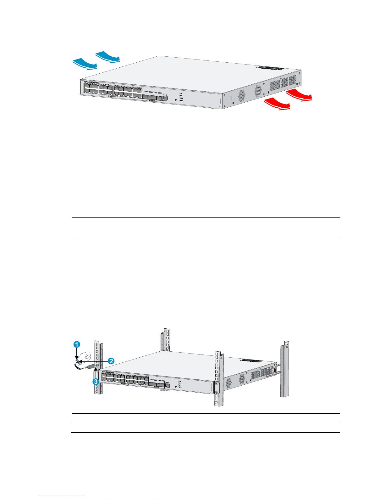
The switch uses left-to-right airflow for heat dissipation. Plan the installation site for adequate ventilation.
• HP recommends that you leave a minimum of 10 cm (3.94 in) of clearance around the air vents.
• Make sure the rack is well ventilated.
Page 8
4
Figure 1 Airflow through the switch chassis
ESD prevention
To prevent electrostatic discharge (ESD), follow these guidelines:
• Ground the switch properly. For how to ground your switch, see "Grounding the switch."
• T
ake dust-proof measures for the equipment room. For more information, see "Cleanness."
• Maintain the humidity and temperature at a proper level. For more information, see "Temperature
and h
umidity."
• Always wear an ESD-preventive wrist strap. Make sure the wrist strap makes good skin contact and
is well grounded when installing the transceiver module.
NOTE:
The ESD-preventive wrist strap is not provided with the switch. Order it yourself.
To attach an ESD-preventive wrist strap:
1. Wear the wrist strap on your wrist.
2. Lock the wrist strap tight around your wrist to maintain good contact with the skin.
3. Secure the wrist strap lock and the alligator clip lock together.
4. Attach the alligator clip to the rack.
5. Make sure the rack is well grounded.
Figure 2 Attaching an ESD-preventive wrist strap
(1) ESD-preventive wrist strap (2) Lock
(3) Alligator clip
Page 9
5
EMI
All electromagnetic interference (EMI) sources, from either outside or inside of the switch and application
system, adversely affect the switch in a conduction pattern of capacitance coupling, inductance coupling,
electromagnetic wave radiation, or common impedance (including grounding system) coupling. To
prevent EMI, follow these guidelines:
• Use a socket with three pins and PE wire to prevent interference from the power grid.
• Use a grounding system and a lightning protection system for the switch separate from those for
other electric equipment, and keep them far away as possible.
• Keep the switch far away from radio transmitting stations, radar stations, and high-frequency
devices.
• Use electromagnetic shielding, for example, shielded interface cables, when necessary.
Lightning protection
To better protect the switch from lightning, follow these guidelines:
• Make sure the grounding cable of the chassis is well grounded.
• Make sure the grounding terminal of the AC power receptacle is well grounded.
• Install a lightning protector at the input end of the power supply to enhance the lightning protection
capability of the power supply.
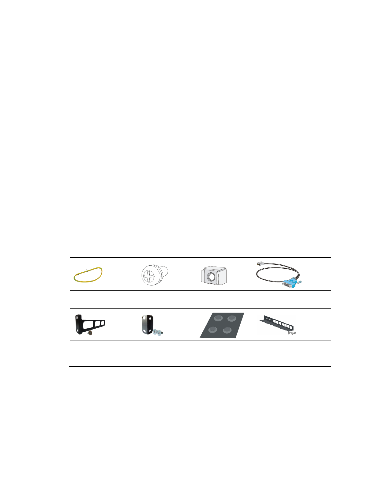
Accessories
Accessories are provided with the switch.
Grounding cable
M6 screw (user
supplied)
Cage nut (user
supplied)
Console cable
Rear mounting bracket
and load-bearing screw
Front mounting
bracket and M4
screws
Rubber feet
Guide rail and screws
(optional)
Page 10

6
Installation preparation checklist
Table 4 Installation preparation checklist
Item Requirements Result
Installation
site
Ventilation
• There is a minimum clearance of 10 cm (3.9 in) around
the inlet and exhaust vents for heat dissipation of the
switch chassis.
• A ventilation system is available at the installation site.
Temperature 0°C to 45°C (32°F to 113°F)
Relative humidity 5% to 95% (noncondensing)
Cleanness
• Dust concentration ≤ 3 × 10
4
particles/m3
• No dust on desk within three days
ESD prevention
• The equipment and rack are well grounded.
• The equipment room is dust-proof.
• The humidity and temperature are at a proper level.
• Wear an ESD-preventive wrist strap. Make sure the wrist
strap makes good skin contact and is well grounded
when installing FRUs.
• Place the removed interface card on an antistatic
workbench, with the face upward, or put it into an
antistatic bag.
• Touch only the edges instead of electronic components
when observing or moving a removed interface card.
EMI prevention
• Take effective measures to protect the power system from
the power grid system.
• Separate the protection ground of the switch from the
grounding device or lightning protection grounding
device as far as possible.
• Keep the switch far away from radio stations and radar
and high-frequency devices working in high current.
• Use electromagnetic shielding when necessary.
Lightning
protection
• The grounding cable of the chassis is well grounded.
• The grounding terminal of the AC power receptacle is
well grounded.
• A port lightning arrester is installed. (Optional)
Electricity safety
• Equip a UPS.
• In case of emergency during operation, switch off the
external power switch.
Page 11

7
Item Requirements Result
Rack-mounting
requirements
• Install the switch in an open rack if possible. If you install
the switch in a closed cabinet, make sure that the cabinet
is equipped with a good ventilation system.
• The rack is sturdy enough to support the weight of the
switch and installation accessories.
• The size of the rack is appropriate for the switch.
• The front and rear of the rack are at least 0.8 m (31.50 in)
away from walls or other devices.
Safety
precautions
• The switch is far away from any moist area and heat source.
• You have located the emergency power switch in the equipment room.
Tools User-supplied tools.
Reference
• Documents shipped with the switch.
• Online documents.
Page 12

8
Installing the switch
CAUTION:
• Keep the tamper-proof seal on a mounting screw on the chassis cover intact. If you want to open the
chassis, contact HP Support for permission. Otherwise, HP will not be liable for any consequence
caused thereby.
• To avoid injury, do not touch bare wires, terminals, or parts with high-voltage hazard signs.
Confirming installation preparations
Before you install the switch, verify that you have read "Preparing for installation" carefully and that the
installation site meets all the requirements.
Page 13
9
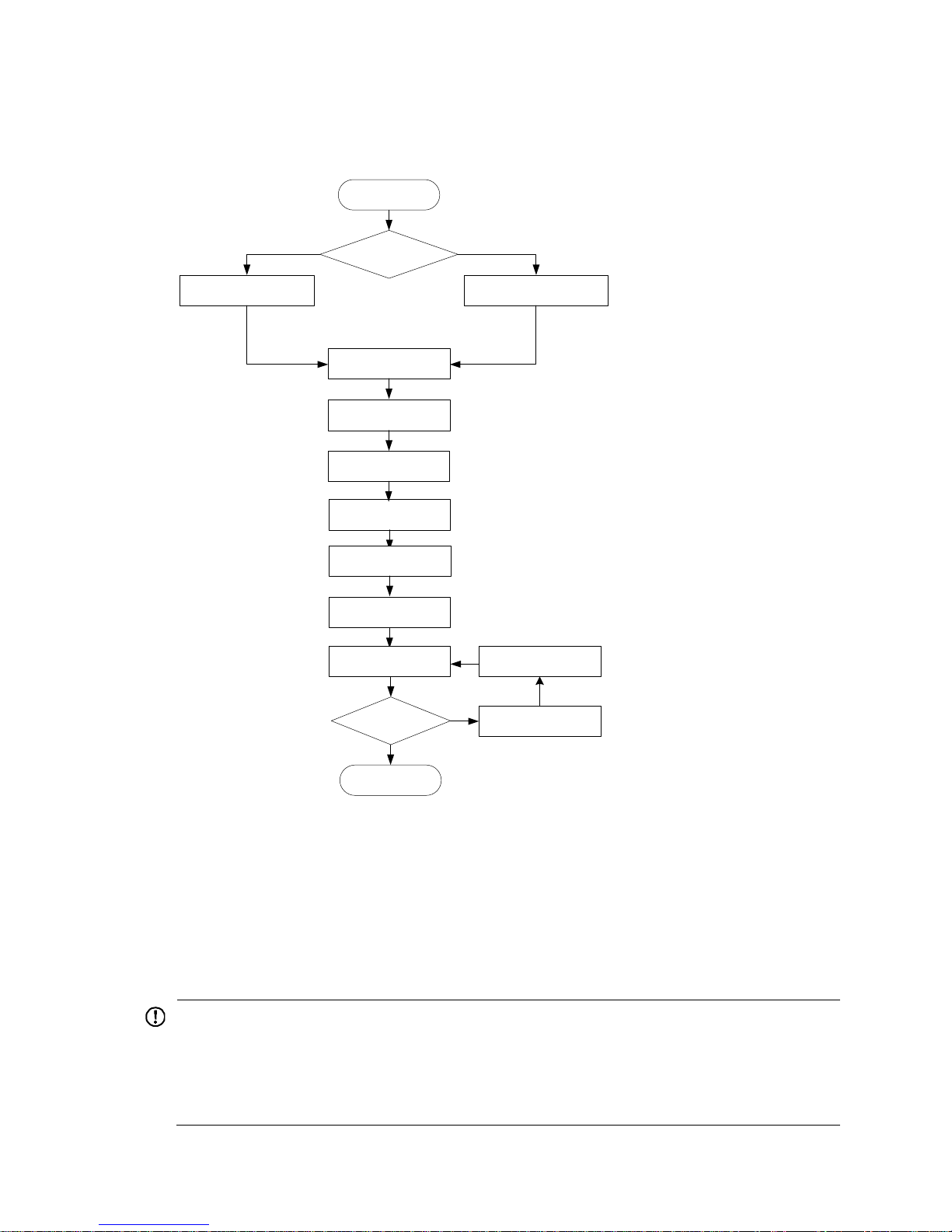
Installation flow
Figure 3 Switch installation flow
Mounting the switch on a workbench
If a standard 19-inch rack is not available, you can place a switch on a clean, flat workbench, as follows:
1. Verify that the workbench is sturdy and well grounded.
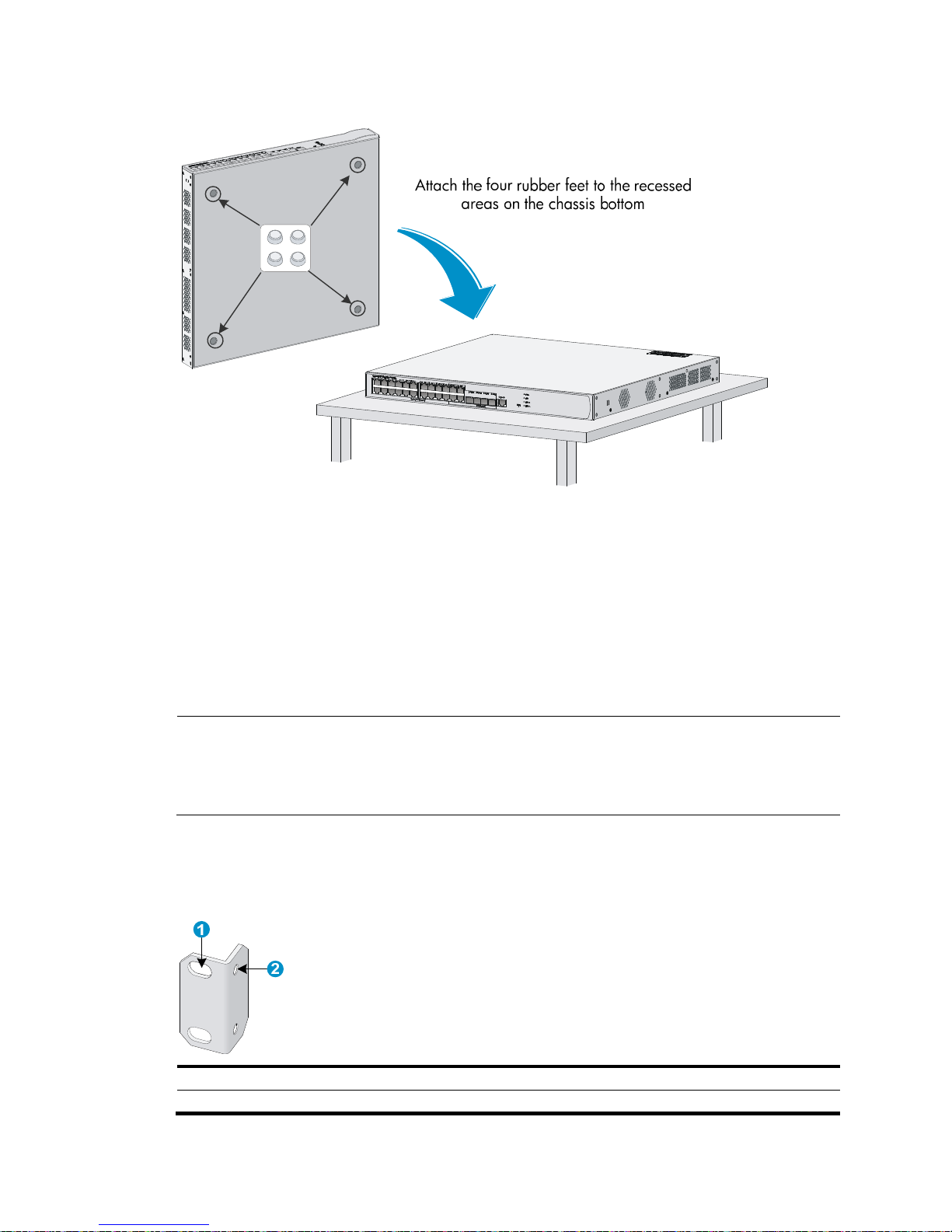
2. Attach the four rubber feet to the recessed areas on the chassis bottom.
3. Place the switch on the workbench.
IMPORTANT:
• Ensure good ventilation and at least 10 cm (3.9 in) of clearance around the chassis for heat dissipation.
• Avoid placing heavy objects on the switch.
• Keep at least a vertical distance of 1.5 cm (0.59 in) between switches when they are placed one above
the other.
Install the switch
Install the switch to a 19-in rack
Mount the switch to a
workbench
Ground the switch
Install a lightning protector
for a port (optional)
Connect interface cables
Connect the power cord
Power on the switch
Operating properly?
Yes
End
No
Power off the switch
Troubleshoot the switch
Start
Install interface modules
Connect the AC power
supply to power strip
(optional)
Page 14
10
Figure 4 Mounting the switch on a workbench
Installing the switch in a 19-inch rack
The switch can be installed in a standard 19-inch rack. Installation falls into one of the following
scenarios:
• Installing the switch with front and rear mounting brackets.
• Installing the switch with front mounting brackets and a rack shelf.
• Installing the switch with front mounting brackets and slide rails.
NOTE:
• The front mounting brackets can be used only for securing the switch, rather than bearing weight.
• You can install the mounting brackets to the two sides of the front panel or rear panel. This section
installs the mounting brackets to the two sides of the front panel.
Mounting brackets
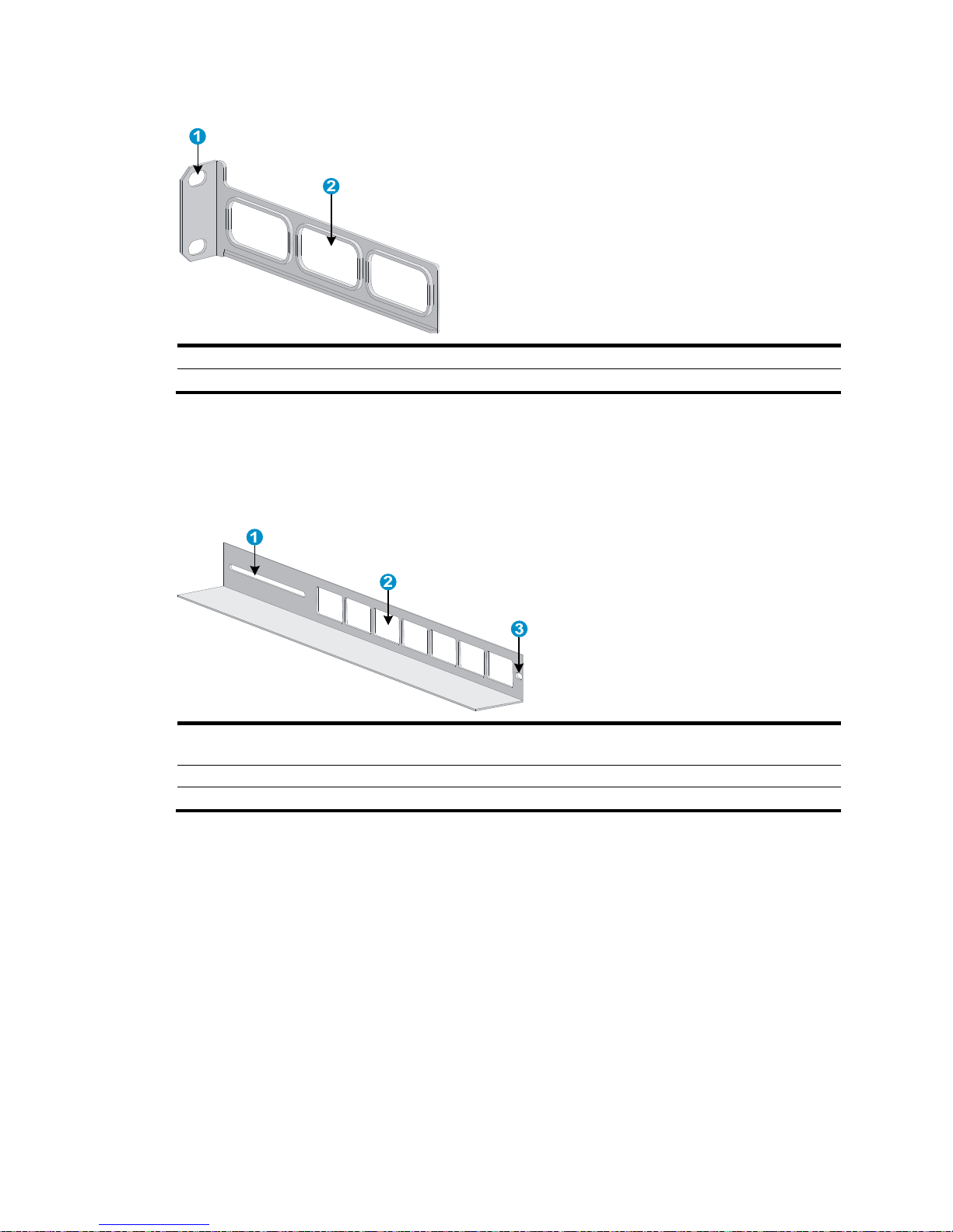
Figure 5 Front mounting bracket
(1) Screw holes for fixing the front mounting bracket onto the rack (using M6 screws)
(2) Screw hole for fixing the front mounting bracket to the switch chassis
Page 15
11
Figure 6 Rear mounting bracket
(1) Screw holes for fixing the rear mounting bracket onto the rack (using M6 screws)
(2) Heat dissipation holes
Slide rails
The slide rails are optional components that need to be separately ordered.
Figure 7 Slide rail
(1) Slot hole for fixing the slide rail onto the rear bracket of the rack. It allows adjustment of the switch mounting
screw position accordin
g
to the switch position.
(2) Heat dissipation holes. Holes for heat dissipation between the switch and the rack.
(3) Slot hole for fixing the slide rail onto the front bracket of the rack.
Installing the switch by using front and rear mounting brackets
1. Wear an ESD-preventive wrist strap, and make sure the rack is sturdy and properly grounded.
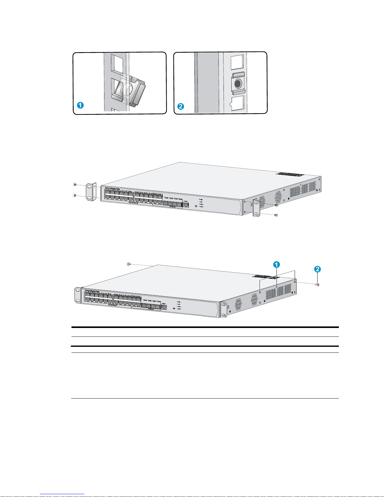
2. Mark the position on the rack for installing the slide rail, and install the cage nuts.
Page 16
12
Figure 8 Installing cage nuts
3. Use the screws packed with the front mounting brackets to secure the front mounting brackets on
both sides of the switch. See Figure 9.
Figure 9 Attaching th
e front mounting brackets to both sides of the switch
4. Attach the weight-bearing screws packed with the rear mounting brackets on both sides of the
switch. See Figure 10.
Figure 10 Installing the
weight-bearing screws
(1) Three holes for mounting the weight-bearing screw (select one as needed)
(2) Weight-bearing screw
NOTE:
One rack unit has three holes, the middle of which is an auxiliary installation hole, and the other two are
standard installation holes. You can distinguish them by the space between each two holes. The space
between a standard installation hole and an auxiliary installation hole is wider than that between two
adjacent standard installation holes.
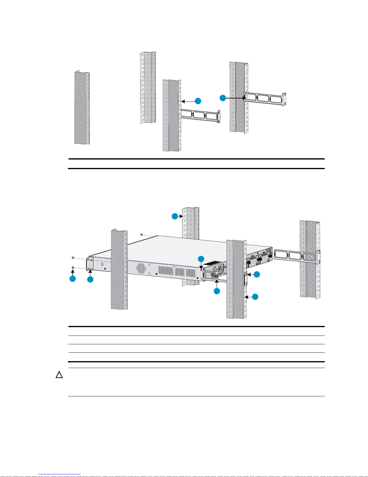
5. Determine the switch installation position in the rack and use screws and cage nuts to attach the
rear mounting brackets on the rear square-holed brackets of the rack. See Figure 11.
Page 17
13
Figure 11 Installing rear mounting brackets
(1) Rear square-holed brackets (2) Rear mounting bracket
6. Hold the bottom of the switch with one hand and the front part with the other hand, and gently push
the switch into the rack. See Figure 12.
Figure 12 Installing the
switch by using front and rear mounting brackets
(1) Screw for fixing the front mounting bracket (2) Front mounting bracket
(3) Front square-holed bracket (4) Weight-bearing screw
(5) Rear mounting bracket (6) Screw for fixing the rear mounting bracket
(7) Rear square-holed bracket
CAUTION:
A
fter pushing the switch into the rack, make sure the upper edges of the rear mounting brackets fixed on
the rack have close contact with the weight-bearing screws on the switch. See Figure 13.
2
1
1
2
3
4
5
6
7
Page 18
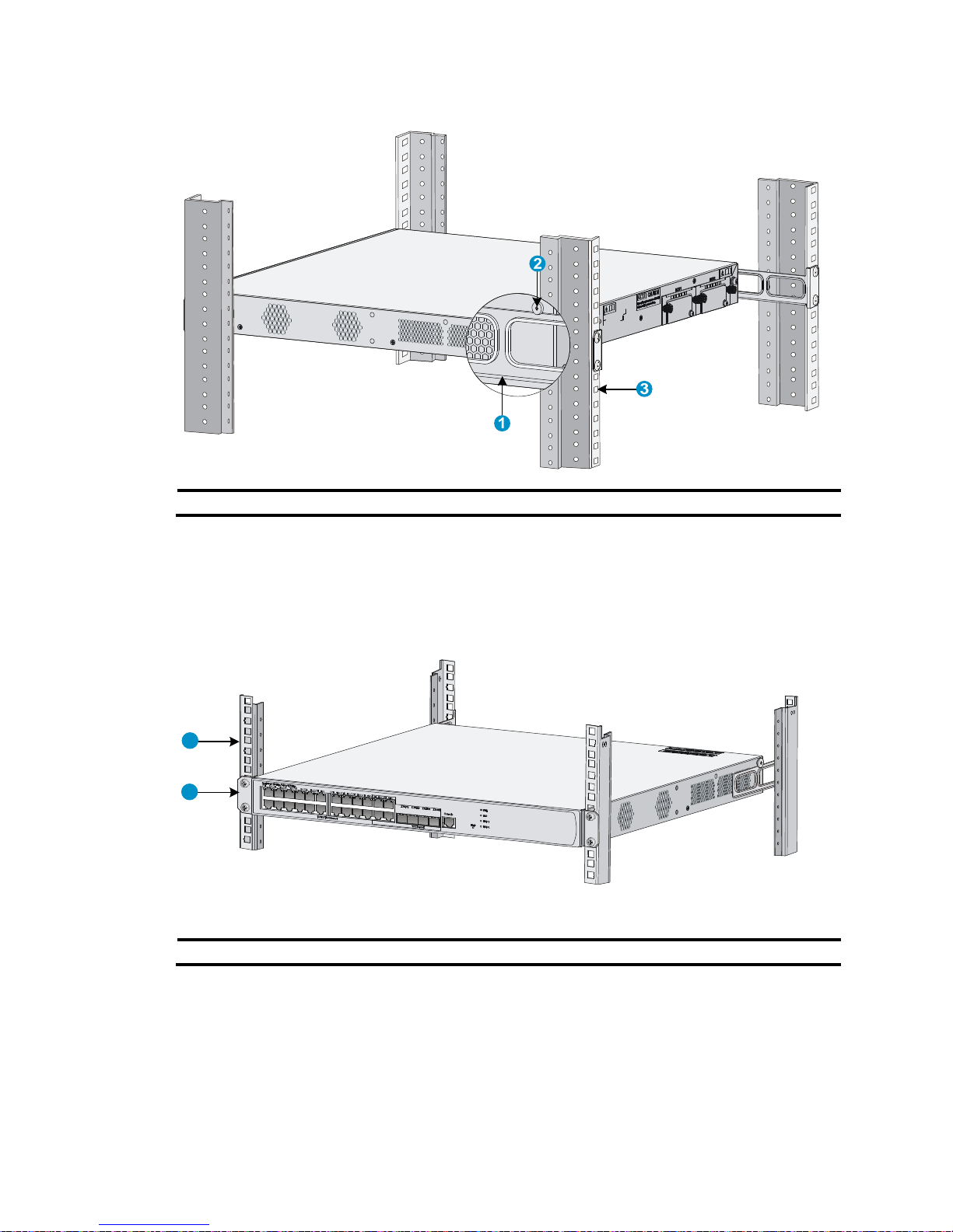
14
Figure 13 Installation complete
(1) Rear mounting bracket (2) Weight-bearing screw (3) Rear square-holed bracket
7. Attach the front mounting brackets to the front square-holed brackets of the rack with screws and
cage nuts. Make sure the switch is secured to the rack through the front and rear mounting brackets.
See Figure 14.
Figure 14 Installation co
mplete
(1) Front square-holed bracket (2) Front mounting bracket
Installing the switch by using front mounting brackets and a
rack shelf
The rack shelf is an optional component that needs to be separately ordered if needed.
To install the switch in a rack using front mounting brackets and a rack shelf:
1
2
Page 19
15
1. Wear an ESD-preventive wrist strap, and verify that the rack is sturdy and properly grounded.
2. Use the screws packed with the front mounting brackets to attach the front mounting brackets to
both sides of the switch. See Figure 9.
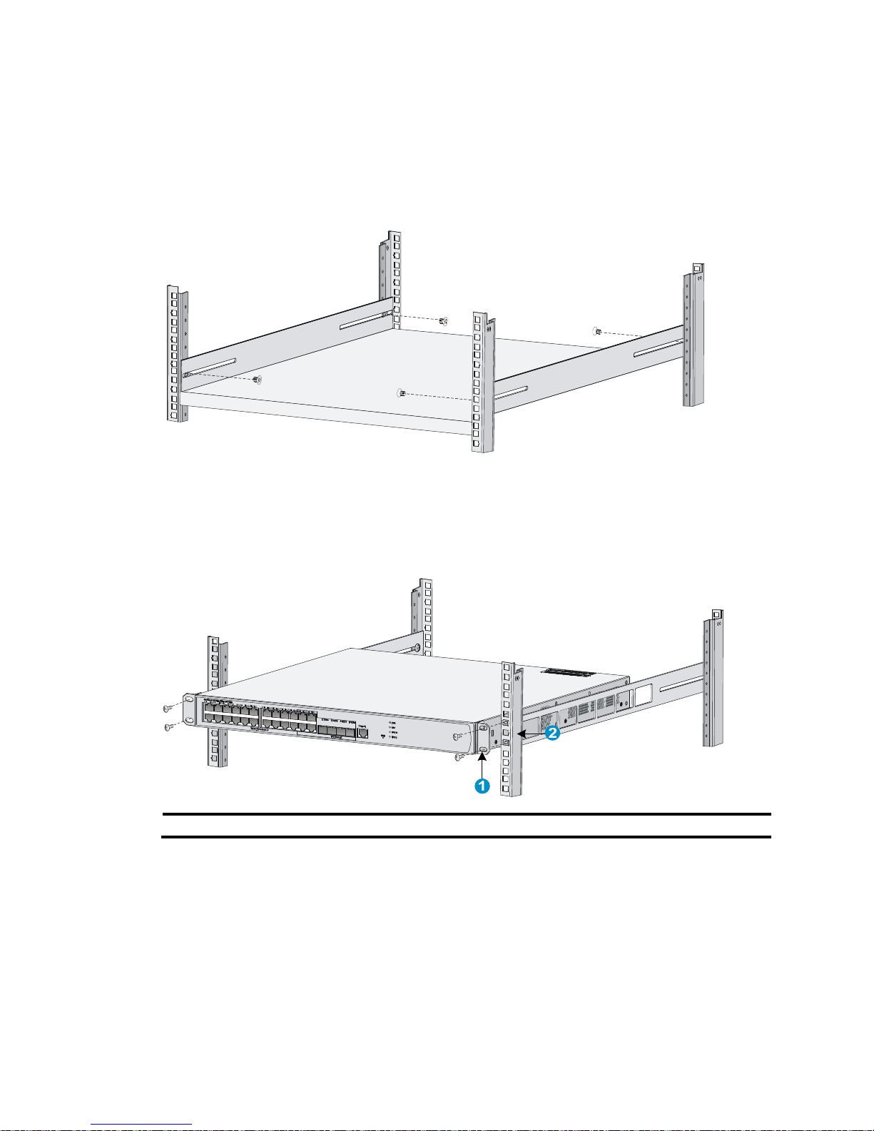
3. Install the rack shelf on the rack. (See Figure 15. This figure is for reference only and may differ
from the actual installation on your rack.)
Figure 15 Installing a rack shelf
4. Place the switch horizontally on the rack shelf, push it into the rack along the rack shelf, and secure
the front mounting brackets onto the front square-holed brackets of the rack by using the screws
and cage nuts. See Figure 16.
Figure 16 Installing the
switch using front mounting brackets and a rack shelf
(1) Front mounting bracket (2) Front square-holed bracket
Installing the switch by using front mounting brackets and slide
rails
1. Wear an ESD-preventive wrist strap, and verify that the rack is sturdy and properly grounded.
2. Use the screws packed with the front mounting brackets to attach the front mounting brackets to
both sides of the switch. See Figure 9.
3. Attach the slide rails to both sides of the rack with M5 self-tapping screws. (See Figure 17. This
figure is for reference only and may differ from the actual installation on your rack and slide rails.)
Page 20
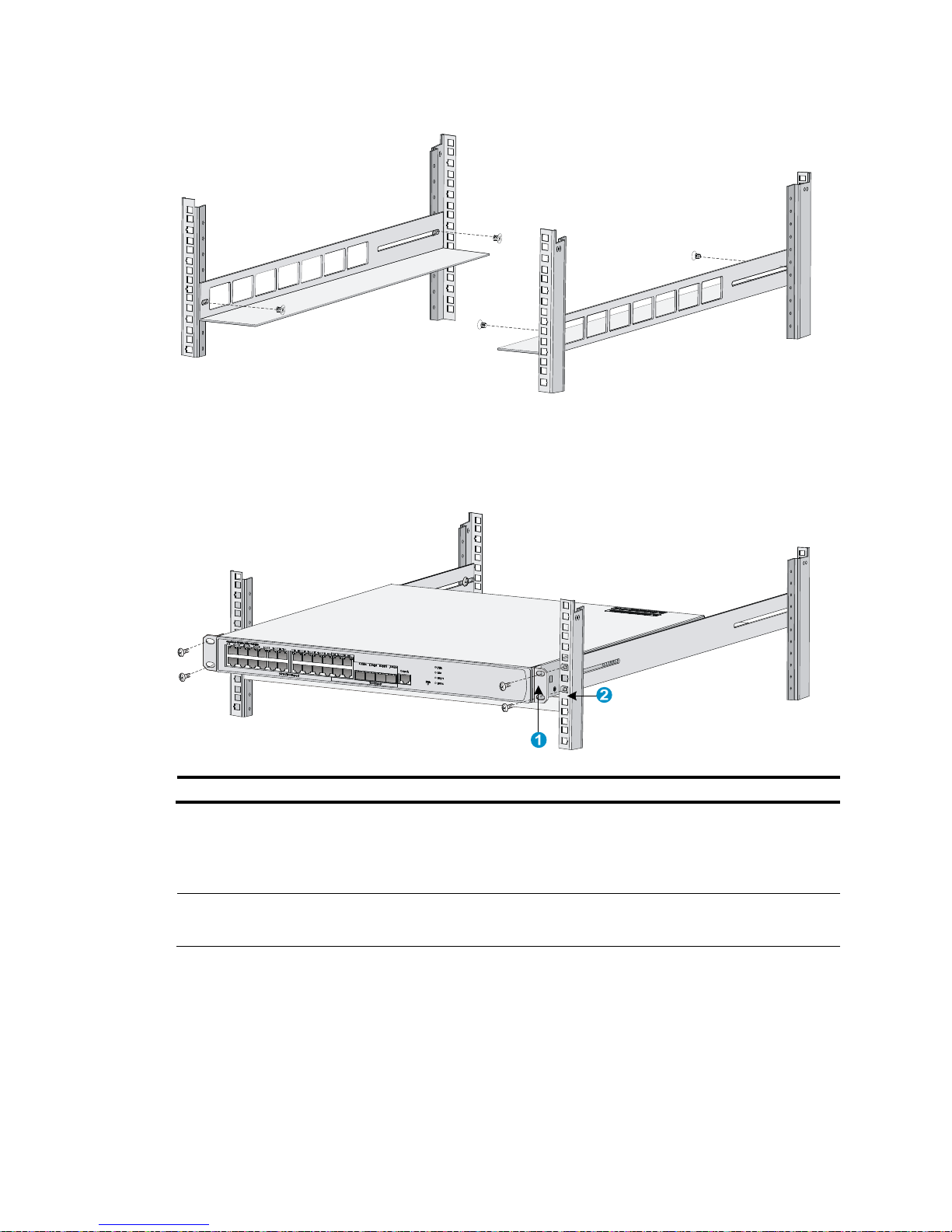
16
Figure 17 Installing slide rails
4. Hold the switch by both sides of it, and gently push it into the rack along the slide rails (see Figure
18). Verify that the bottom of the switch is in firm contact with the slide rails.
Figure 18 Installing the switch by using front mounting brackets and slide rails
(1) Front mounting bracket (2) Front square-holed bracket
5. Attach the front mounting brackets to the front square-holed brackets of the rack by using the M6
screws and cage nuts. Make sure the switch is secured to the rack through the front mounting
brackets and slide rails.
NOTE:
Keep a distance of at least 1 U (44.45 mm/1.75 in) between two devices to ensure
g
ood heat dissipation.
Page 21
17
Grounding the switch
W
ARNING!
• Connecting the switch grounding cable correctly is crucial to lightning and EMI protection.
• Connect the grounding cable to the grounding system in the equipment room. Do not connect it to a fire
main or lightning rod.
The power input end of the switch has a noise filter, whose central ground is directly connected to the
chassis to form the chassis ground (commonly known as PGND). You must securely connect this chassis
ground to the earth so the faradism and leakage electricity can be safely released to the earth to
minimize EMI susceptibility of the switch.
You can ground the switch by using one of the following methods, depending on the grounding
conditions available at the installation site:
• Grounding the switch with a grounding strip (recommended
• Grounding the switch with a grounding conductor buried in the earth
• Grounding the switch through the PE wire of an AC power cord
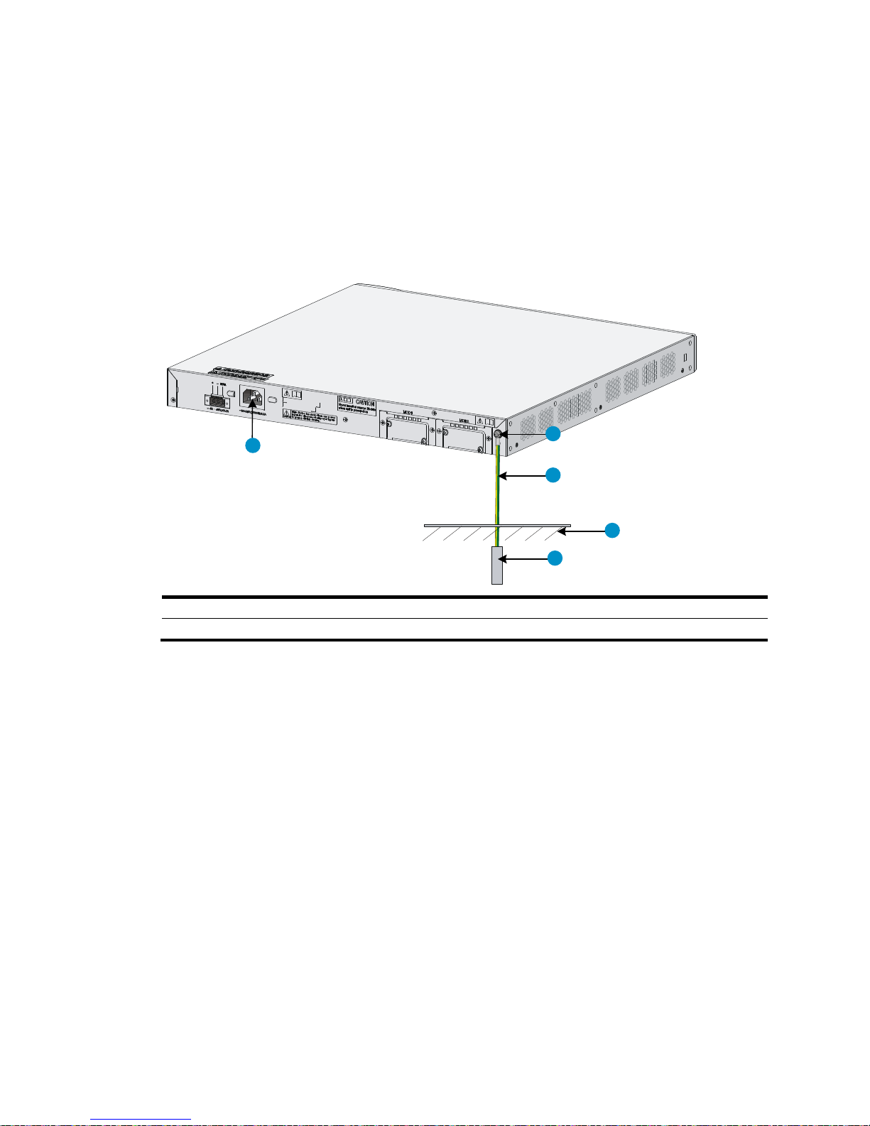
Grounding the switch with a grounding strip (recommended
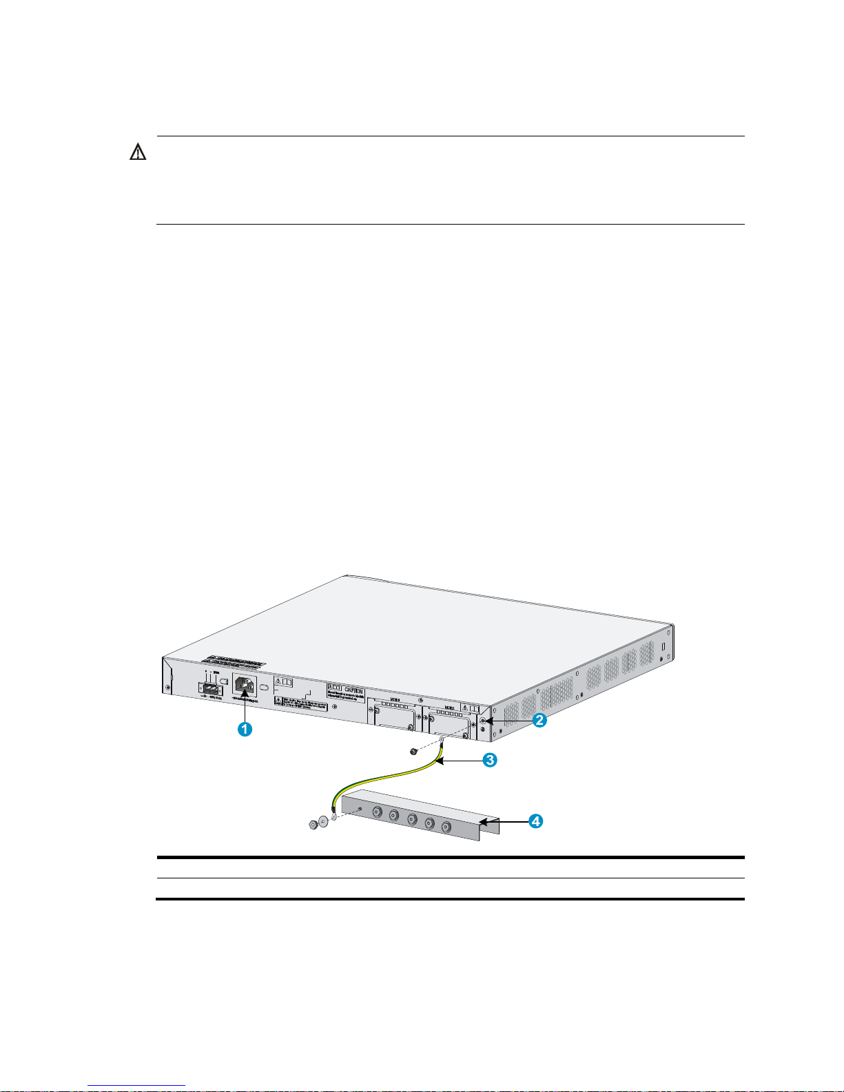
Attach one end of the yellow-green grounding cable of the switch to the grounding post on the chassis
with a grounding screw and the other end to the grounding terminal on the grounding strip, and fasten
the nut.
Figure 19 Connecting the grounding cable to a grounding strip
(1) AC power receptacle (2) Grounding hole
(3) Grounding cable (4) Grounding strip
Page 22
18
Grounding the switch with a grounding conductor buried in the
earth
If the installation site has no grounding strips but earth ground is available, hammer a 0.5 m (1.64 ft) or
longer angle iron or steel tube into the earth to serve as a grounding conductor.
Weld the yellow-green grounding cable to the angel iron or steel tube, and treat the joint for corrosion
protection.
Figure 20 Grounding the switch by burying the grounding conductor into the earth
(1) AC power receptacle (2) Grounding screw (3) Grounding cable
(5) Angle iron (4) Earth
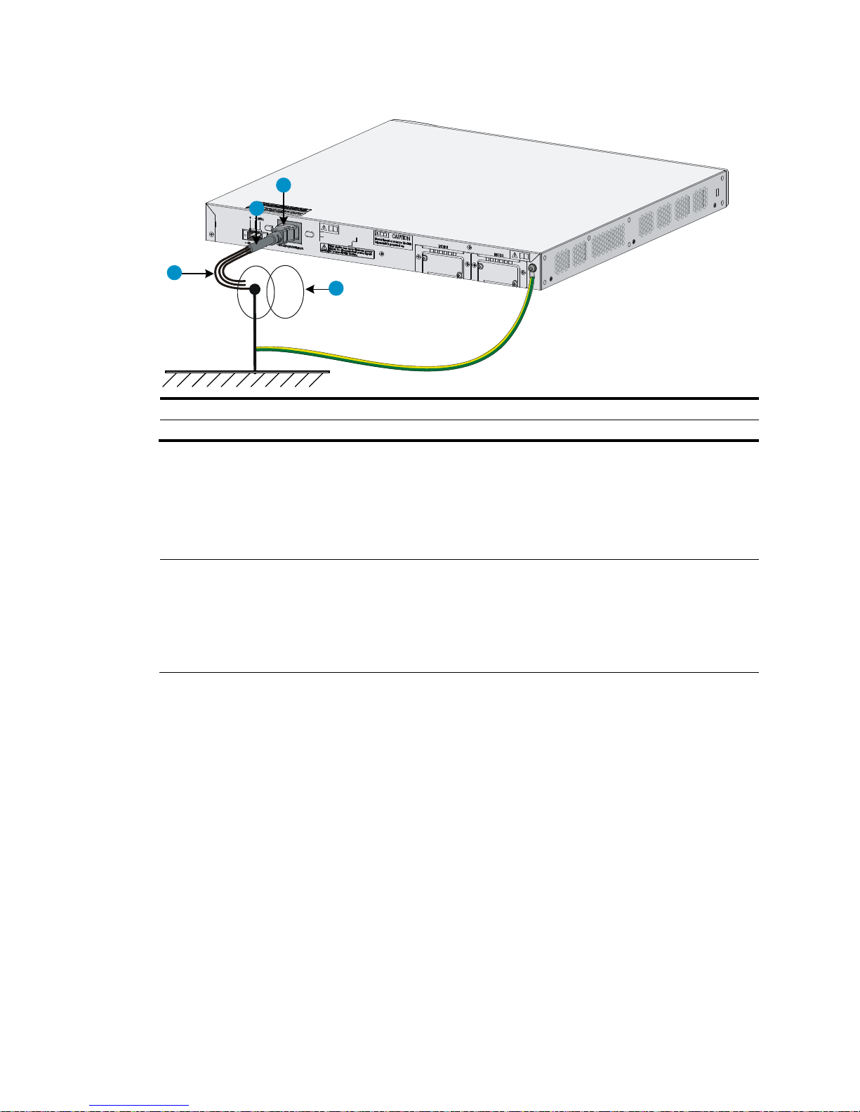
Grounding the switch through the PE wire of an AC power cord
If the installation site has no grounding strips or earth ground, you must ground an AC-powered switch
through the protective earth (PE) wire of the power cord. Verify that the ground contact in the power outlet
is well connected to the ground in the power distribution room or on the AC transformer side.
1
2
3
4
5
Page 23
19
Figure 21 Grounding the switch through the PE wire of an AC power cord
(1) Three-core AC power cord (2) AC power receptacle
(3) PE wire (4) Power transformer
Installing a lightning protector for a network port
(optional)
NOTE:
• HP recommends that you install a lightning protector for 10/100/1000 Mbps RJ-45 copper Ethernet
ports.
• Before installing the lightning protector, read the instructions that come with the lightning protector.
• A lightning protector is not provided with the switch.
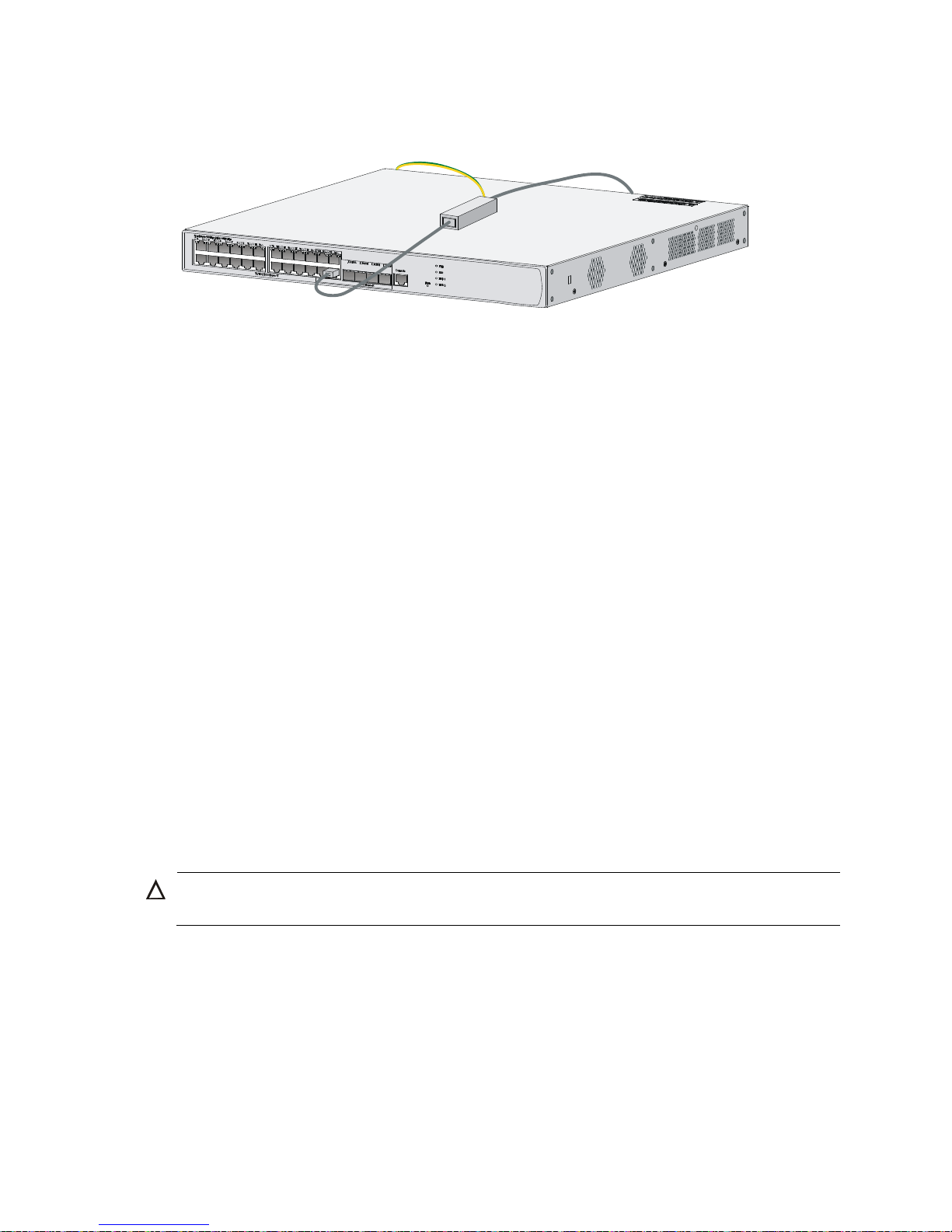
If part of the network cable of a 10/100/1000 Mbps RJ-45 copper Ethernet port must be routed
outdoors, connect a lightning protector to the cable before you plug the cable into the port.
Installation procedures
To install a port lightning protector:
1. Use a double-faced adhesive tape to stick the lightning protector onto the switch chassis, and make
sure it is as close to the grounding screw of the switch as possible.
2. Measure the distance between the protector and the grounding screw of the switch, cut the ground
wire of the protector as appropriate, and securely tighten the ground wire to the grounding screw
of the switch.
3. Use the multimeter to measure whether the ground wire of the protector makes good contact with
the grounding screw of the chassis.
4. Insert the outdoor network cable into the protector's Surge end, and insert the cable connected to
the switch into the Protect end. Examine the indicators on the lightning protector to verify that the
connection is correct.
1
2
3
4
Page 24
20
5. Use nylon ties to bundle the cables.
Figure 22 Installing a lightning protector for a network port
Precautions
If the performance of the port lightning protector is adversely affected in the following situations, follow
the recommended solution:
• Problem 1—The port lightning protector is installed in reverse direction.
Solution—Connect the Surge end to the outdoor network cable and the Protect end to the network
port on the switch.
• Problem 2—The port lightning protector is not well grounded.
Solution—After the connection, use the multimeter to confirm that the ground wire for the protector
is as short as possible to make sure it makes good contact with the grounding screw of the switch.
• Problem 3—The installed port lightning protectors are not sufficient.
Solution—If the switch has more than one network port connected to other devices through outdoor
cables, install a lightning protector for each network port.
Connecting the AC power supply to a power strip
with lightning protection
If part of the AC power line is routed outdoors, use a power strip with lightning protection to connect the
AC power cord of the switch to the AC power line to protect the switch from being damaged by lightning
strikes.
You can attach the power strip to the rack, workbench, or wall of equipment room.
CAUTION:
Make sure the PE terminal of the power socket has been securely grounded.
After you connect the AC power cord from the switch to a socket on the power strip, verify that the green
RUN LED on the strip is on and the red LED is off.
If the red LED is on, use a multimeter to examine the polarity of the wires in the power socket for wrong
connections. If the zero wire (left) and the live wire (right) are correctly connected, check for a missing
grounding connection.
Page 25
21
Connecting the interface cables
Connecting the console cable
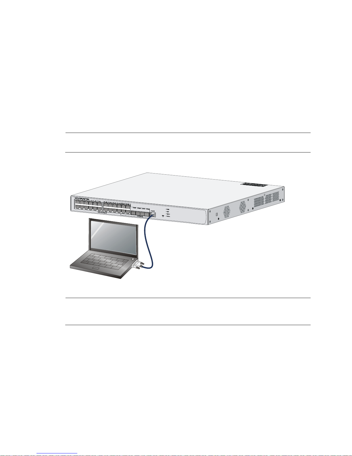
1. Prepare a configuration terminal:
The configuration terminal can be an ASCII terminal with an RS232 serial port or a PC. The
description in this section assumes that you use a PC as the configuration terminal.
2. Connect the console cable:
a. Plug the DB-9 female connector of the console cable into the serial port of the PC.
b. Connect the RJ-45 connector to the console port of the switch.
NOTE:
Identify the mark on the console port, and make sure you are connecting to the correct port.
Figure 23 Connecting the console cable
NOTE:
If the switch has been powered on, connect the console cable to the PC before connecting it to the switch.
W
hen you disconnect the cable, first disconnect it from the switch.
Setting terminal parameters
To configure and manage the switch, you must run a terminal emulator program on the console terminal.
The required terminal settings are as follows:
• Bits per second—9600
• Data bits—8
• Parity—None
• Stop bits—1
• Flow control—None
Page 26
22
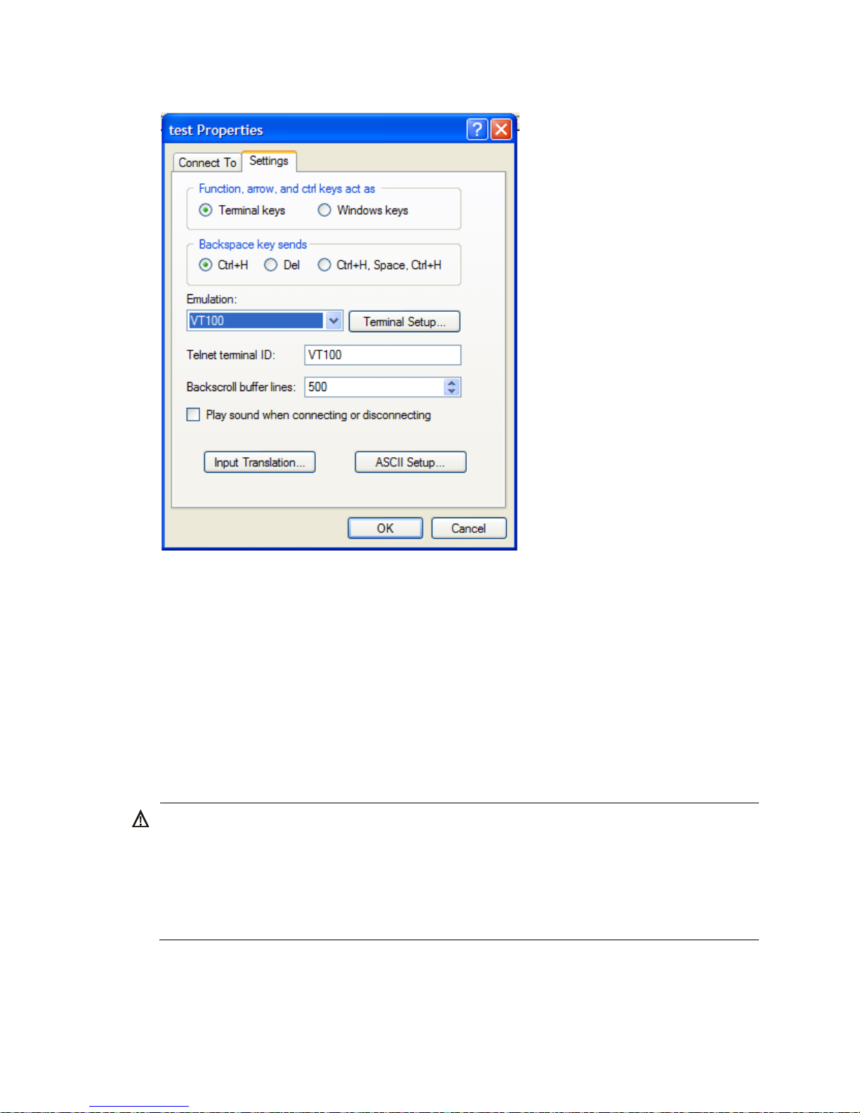
• Emulation—VT100
To set terminal parameters, for example, on a Windows XP HyperTerminal:
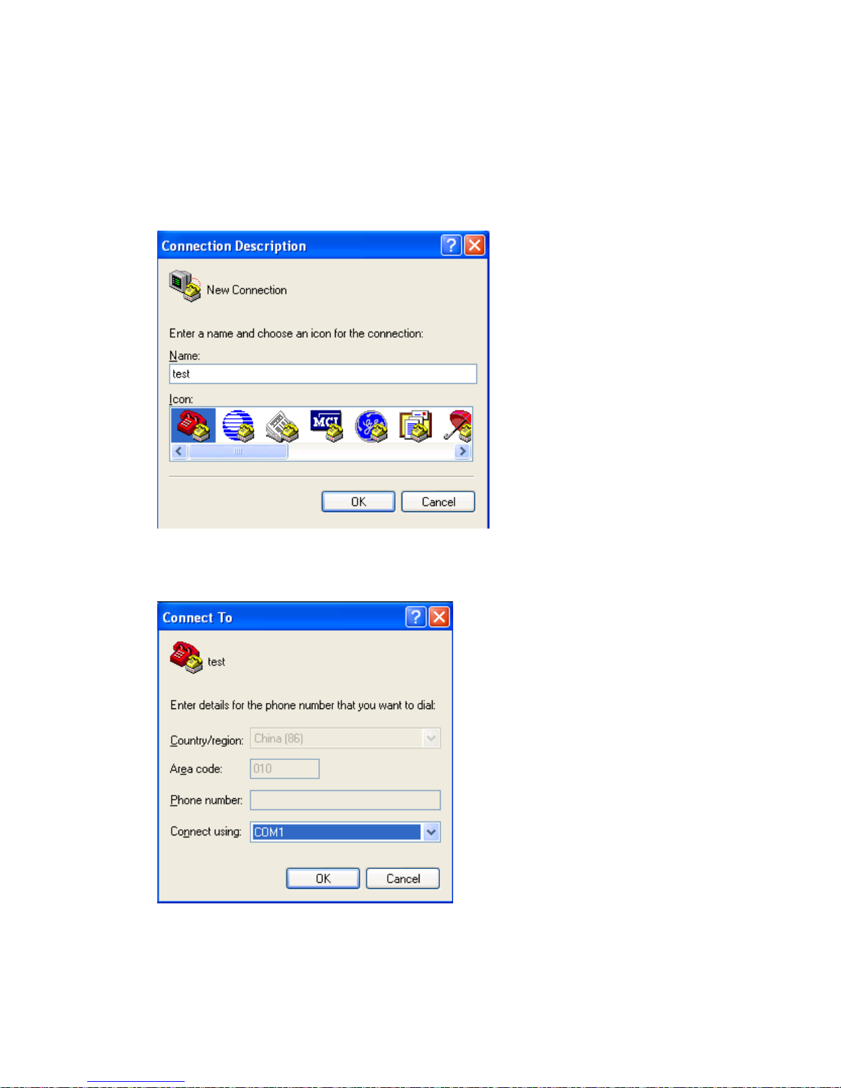
1. Select Start > All Programs > Accessories > Communications > HyperTerminal.
The Connection Description dialog box appears.
2. Enter the name of the new connection in the Name field, and click OK.
Figure 24 Connection description
3. Select the serial port to be used from the Connect using list, and click OK.
Figure 25 Setting the serial port used by the HyperTerminal connection
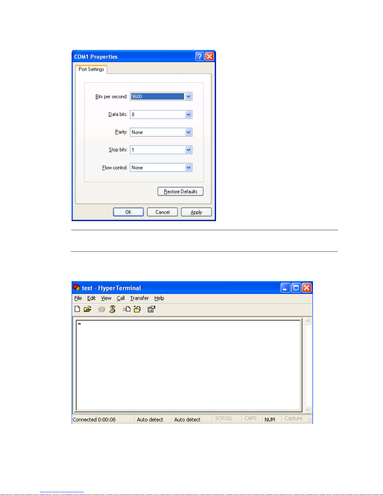
4. Set Bits per second to 9600, Data bits to 8, Parity to None, Stop bits to 1, and Flow control to None,
and click OK.
Page 27
23
Figure 26 Setting the serial port parameters
NOTE:
To restore the default settings, click Restore Defaults.
5. Select File > Properties in the HyperTerminal window.
Figure 27 HyperTerminal window
6. On the Settings tab, set the emulation to VT100, and click OK.
Page 28
24
Figure 28 Setting the terminal emulation
Connecting the Ethernet cables
Connecting a copper Ethernet port
1. Connect one end of the Ethernet cable to the copper Ethernet port on the switch, and the other end
to an Ethernet port of the peer switch.
2. After powering on the switch, examine the LEDs of the fixed copper Ethernet port.
For more information about the LED description, see "Appendix A Chassis views and tec
hnical
specifications."
Connecting a fiber Ethernet port
W
ARNING!
W
hen you connect a fiber:
• Never bend or curve a fiber with a fierce force. The bend radius of a fiber must not be less than 10 cm
(3.94 in).
• Make sure the TX and RX ports on a transceiver module are correctly connected.
• Keep the fiber end clean.
The switch does not include a transceiver module. HP transceiver modules are recommended. For
transceiver module specifications, see "Appendix A Chassis views and technical specifications."
T
o connect a 1000 Mbps fiber port:
Page 29
25
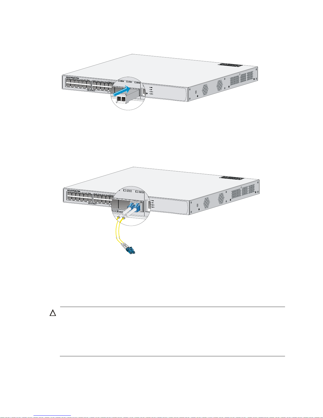
1. Identify the top side of the SFP module, and gently insert it into the socket.
Figure 29 Inserting a transceiver module
2. Identify the Rx and Tx ports on the transceiver module, and plug the two LC connectors at one end
of the fiber into the Rx and Tx ports.
3. Plug the LC connectors at the other end of the fiber into the Tx and Rx ports on a fiber port on the
peer device.
Figure 30 Connecting fiber connectors
4. After powering on the switch, examine the SFP port LEDs.
For more information about the SFP LEDs, see "Appendix B LEDs."
Installing and removing an HP 830 uplink module)
CAUTION:
W
hen you install or remove the module, follow these guidelines:
• Do not use excessive force in the operation, and do not touch the surface-mounted components directl
y
with your hands.
• After removing the module, if the slot is to remain empty, install a filler panel to prevent dust and ensure
normal ventilation in the switch.
Page 30
26
IMPORTANT:
• The interface cards of the switch are not hot swappable.
• Use the HP 830 unified wired-WLAN switch uplink module together with an XFP transceiver module.
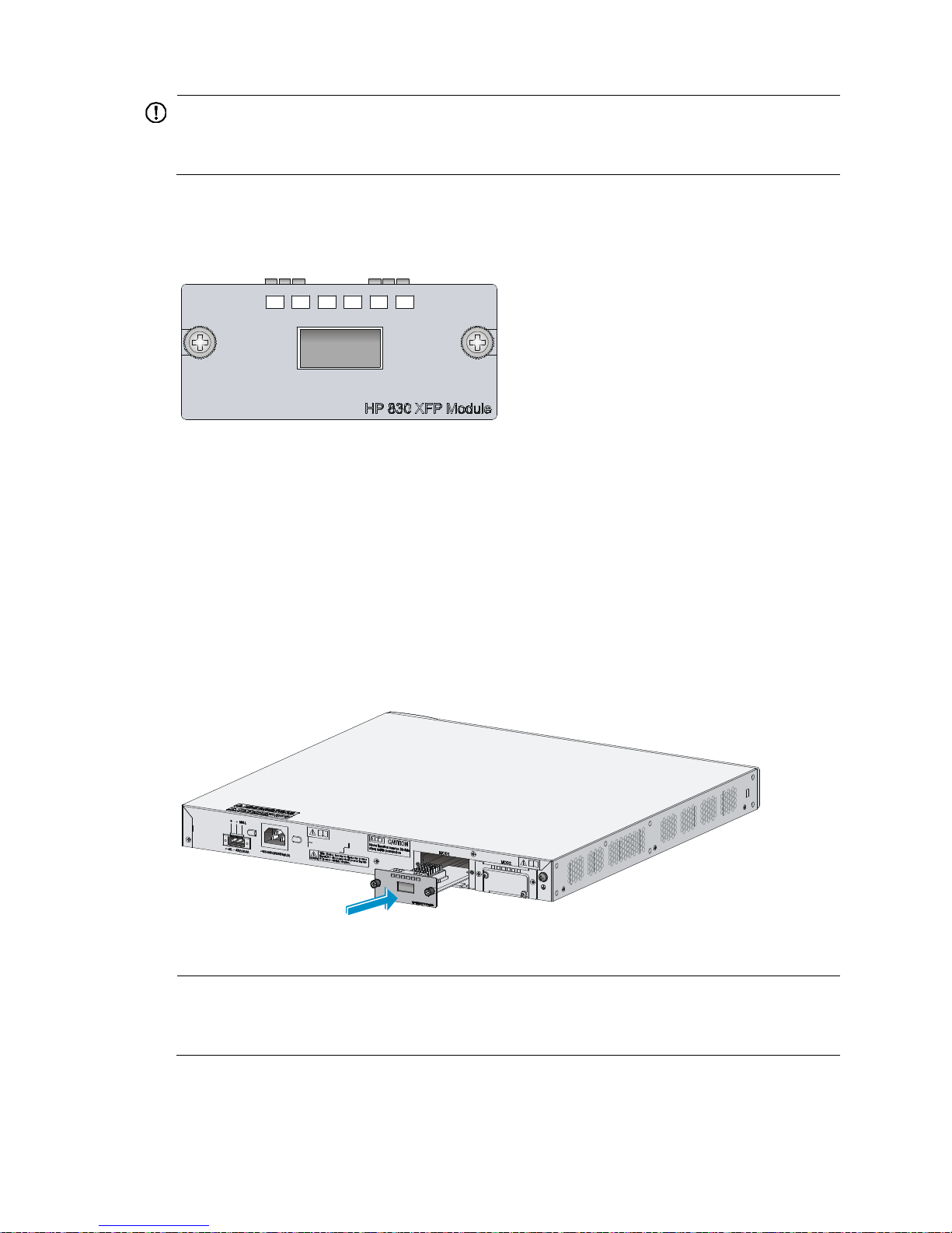
The HP 830 unified wired-WLAN switch uplink module is used for copper-to-fiber and fiber-to-copper
conversion in optical signal transmission. The module requires fiber cables with LC connectors.
Figure 31 Front panel
Installing an HP 830 uplink module
1. Wear an ESD-preventive wrist strap and make sure it makes good skin contact and is well
grounded.
2. Unpack the module.
3. Loosen the captive screws on the filler panel over the module slot with a Phillips screwdriver, and
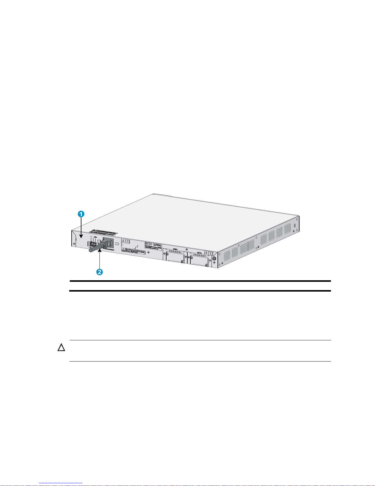
remove the filler panel.
4. Squeezing the module by the captive screws on the front panel, push the module steadily into the
slot along the slide rails until it is firmly seated in the switch.
Figure 32 Installing the module
5. Fasten the captive screws on the module to secure it in place.
NOTE:
• Keep the removed filler panel safe for future use.
• Do not over-tighten the captive screws on the front panel of the module.
Page 31
27
Removing an HP 830 uplink module
1. Wear an ESD-preventive wrist strap, and make sure it makes good skin contact and is well
grounded.
2. Use a Phillips screwdriver to completely loosen the captive screws at both sides of the module.
3. Pull the module outward until it is completely out of the switch chassis.
Connecting the power cord
Connecting an AC power cord
1. Verify that the chassis ground is correctly connected to the earth ground.
2. Connect one end of the AC power cord to the AC-input power receptacle on the switch, and the
other end to the AC power source.
3. Use the cable tie supplied with the switch to secure the power cord to the chassis.
Figure 33 Connecting the AC power cord
(1) Rear panel (2) AC power cord
4. Examine the system LED (PWR) on the front panel of the switch. If the LED is on, the AC power input
is normal.
Connecting the switch to an RPS
CAUTION:
V
erify that the grounding cable is properly connected before powering on the switch.
The RPS power supply is optional. The switch supports RPS power supply model RPS 1600.
To connect the switch to an RPS:
1. Verify that the switch is powered off and the RPS is switched off.
2. Use a Phillips screwdriver to remove the screws on the cover of the DC power receptacle, and take
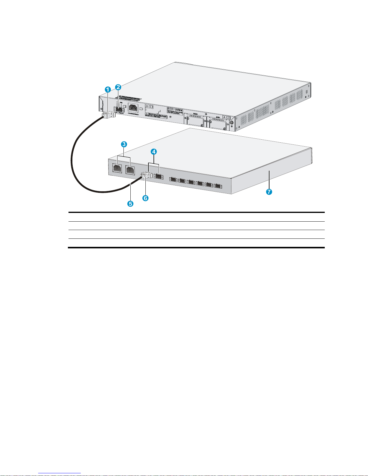
off the cover.
3. Connect the RPS power cord to the DC power receptacle on the chassis.
4. Turn the strain release screws on the RPS power cord clockwise so that the RPS power cord plug
is firmly seated in the DC power receptacle, and then fasten the strain release screws.
Page 32
28
5. Connect the other end of the RPS power cord to an output interface of the RPS.
Figure 34 Connecting the switch to an RPS
(1) RPS power cord plug for the DC power receptacle (2) DC power receptacle
(3) AC power input interfaces of the RPS unit (4) DC output interfaces of the RPS unit
(5) RPS power cord
(6) RPS power cord plug for the RPS output
(7) RPS
6. Examine the RPS LED on the front panel of the switch. LED ON means the RPS unit is correctly
connected.
Verifying the installation
Before powering on the switch, verify that:
• The power supply system meets the switch requirements.
• The grounding cable is correctly connected.
• Both the console cable and power cords are correctly connected.
• All interface cables are routed indoors. If outdoor routing of cables cannot be avoided, verify that
network port lightning arrestors and AC power supply lightning arresters have been correctly
installed.
Powering on the switch
Power on the switch, and you can see the following information:
System is starting...
Press Ctrl+D to access BASIC-BOOTWARE MENU
Booting Normal Extend BootWare
****************************************************************************
Page 33

29
* *
* HP 830 BootWare, Version 2.00 *
* *
****************************************************************************
Copyright (c) 2010-2013 Hewlett-Packard Development Company, L.P.
Compiled Date : Jan 8 2013
CPU Type : XLS208
CPU L1 Cache : 32KB
CPU Clock Speed : 750MHz
Memory Type : DDR2 SDRAM
Memory Size : 512MB
Memory Speed : 533MHz
BootWare Size : 768KB
Flash Size : 1024MB
CPLD Version : 006
PCB Version : Ver.A
BootWare Validating...
Press Ctrl+B to enter extended boot menu...
Press Ctrl + B at the prompt within 4 seconds to access the Boot menu, or wait for the system to
automatically start up. To access the BootWare menu after the system software image files are
decompressed, you must restart the switch.
Starting to get the main application file--flash:/main.bin!............................
............................................
The main application file is self-decompressing ........................................
.....................................................................................
...
.....................................................................................
...
.........Done!
System application is starting...
User interface con0 is available.
Press ENTER to get started.
Press Enter at the prompt, and you can configure the switch when the prompt <HP> appears.
During the startup process, the CPLD is automatically upgraded to the latest version, if any.
After the upgrade process, the system will display this message: "The board cpld update successfully,
please repower device." At this prompt, power off and restart the switch so that the new CPLD version
takes effect.
Page 34

30
Troubleshooting
Power supply failure
If the RPS or PWR LED is off, or if the RPS LED is steady yellow, verify the following items:
• The external AC power system is correctly operating.
• The AC power cord is securely connected to the switch.
• The power cord is in good condition.
NOTE:
• If the problem persists, contact HP Support.
• For more information about RPS and PWR LEDs, see "Appendix B LEDs."
Configuration terminal problems
If the configuration environment setup is correct, the configuration terminal displays booting information
when the switch is powered on. If the setup is incorrect, the configuration terminal either displays nothing
or displays garbled text.
No terminal display
If the configuration terminal displays nothing when the switch is powered on, verify the following items:
• The power supply is supplying power to the switch.
• The console cable is correctly connected.
• The terminal settings are correct.
Garbled terminal display
If terminal display is garbled, verify that the following settings are configured for the terminal, for
example, HyperTerminal:
• Baud rate—9600
• Data bits—8
• Parity—none
• Stop bits—1
• Flow control—none
• Emulation—VT100
Login password loss
To set a new password if you forget the login password:
1. Select 6 from the BootWare menu to start the system without loading the system configuration.
The following information appears:
Flag Set Success.
Page 35

31
2. When the BootWare menu appears again, select 0 to reboot the switch. The following information
appears:
System is rebooting now.
System start booting...
Booting Normal Extend BootWare....
After reboot, the system runs with the initial default configuration, but the original configuration file
is still stored in the storage medium. To restore the original configuration, use the display
saved-configuration command to display the configuration, and copy and execute the
configuration.
3. Set a new password.
<HP>system-view
[HP]user-interface console 0
[HP-ui-console0]authentication-mode password
[HP-ui-console0]set authentication password simple 123456
When you set the password by using the set authentication password { cipher | simple } password
command, follow these guidelines.
{ If the cipher keyword is specified, the password is stored in cipher text. You cannot see the
password by using the display current-configuration command.
{ If the simple keyword is specified, the password is stored in plain text. You can use the display
current-configuration command to view the password in the current configuration.
4. Save the new configuration by using the save command.
HP recommends that you save the configuration to the default configuration file.
<HP> save
Software loading failure
If software loading fails, the system runs the previous software version. To troubleshoot the software
loading failure:
• Verify that the physical ports are correctly connected. If the cable of any port is not connected,
re-connect the cable to the port, and make sure that the physical connection is correct. Load the
software again.
• Check for errors in the software loading process displayed on the HyperTerminal. If errors exist,
correct them, and load the software again.
For example, the software loading failures might occur in the following situations:
• When you use XMODEM to load software, you select a baud rate other than 9600 bps, but you
have not re-set the baud rate for the HyperTerminal.
• When you use TFTP to load software, you entered an incorrect IP address, software name, or TFTP
serve path.
• When you use FTP to load software, you entered an incorrect IP address, software name, username,
or password.
If software loading has failed even if the physical connections are in good condition and the software
loading process does not have any input errors, contact HP Support.
Page 36

32
Hardware management and maintenance
The CLI and outputs depend on the software version that is running on the switch.
Logging in to the switching engine by using OAP
You can log in to the operating system of the switching engine from the controller engine side. Then the
command line interface is switched from the controller engine to the switching engine, where you can
manage the switching engine's system and application software. To return to the command line interface
of the controller engine, press Ctrl + K.
To log in to the switching engine by using OAP at the controller engine side:
Task Command Remarks
Log in to the switching engine by using
OAP at the controller engine side.
oap connect slot slot-number
Required.
Available in user view.
Displaying hardware information for the switch
Displaying software and hardware version information for the
controller engine
Use the display version command to display software and hardware version information about the switch.
The output includes the following information: the current software version, the hardware version, and the
switch operating time. The output depends on the software and hardware version of the switch.
• On the controller engine:
[HP]display version
HP Comware Platform Software
Comware Software, Version 5.20, Beta 3308P16
Copyright (c) 2010-2013 Hewlett-Packard Development Company, L.P.
HP 830 24P uptime is 0 week, 0 day, 0 hour, 55 minutes
HP 830 24P with 1 RMI XLS 208 750MHz Processor
512M bytes DDR2
1024M bytes Flash Memory
Hardware Version is Ver.A
CPLD Version is 006
Basic Bootrom Version is 2.00
Extend Bootrom Version is 2.00
[Slot 0]830 24P LSW Hardware Version is NA
[Slot 1]830 24P Hardware Version is Ver.A
• On the switching engine:
Page 37

33
<HP>display version
HP Comware Platform Software
Comware Software, Version 5.20, Release 3308P16
Copyright (c) 2010-2013 Hewlett-Packard Development Company, L.P.
HP 830 24P LSW uptime is 0 week, 0 day, 0 hour, 56 minutes
HP 830 24P LSW
128M bytes DRAM
256M bytes Nand Flash Memory
Config Register points to Nand Flash
Hardware Version is VER.A
CPLD Version is 006
Bootrom Version is 2.00
[SubSlot 0] 24GE+4SFP+POE Hardware Version is VER.A
[SubSlot 1] 1XFP Hardware Version is VER.B
Displaying operational statistics for the switch
When you perform routine maintenance or the system fails, you might need to display the operational
information of each feature module to locate failures. Typically, you need to run the display commands
individually. However, you can use the display diagnostic-information command in any view to display
or save the operational statistics of multiple feature modules of the switch. This command displays the
output of the display clock, display version, display device, and display current-configuration
commands.
• Save the operational statistics for each feature module of the switch:
<HP>display diagnostic-information
Save or display diagnostic information (Y=save, N=display)? [Y/N]:y
Please input the file name(*.diag)[flash:/default.diag]:aa.diag
Diagnostic information is outputting to flash:/aa.diag.
Please wait...
Save successfully.
Execute the more default.diag command in user view, and then press the Page Up and Page Down
keys to view the contents of the file default.diag.
• Display the operational statistics for each feature module of the switch. (Details not shown.)
<HP>display diagnostic-information
Save or display diagnostic information (Y=save, N=display)? [Y/N]:n
=================================================================
===============running CPU usage information===============
=================================================================
===== Current CPU usage info =====
CPU Usage Stat. Cycle: 49 (Second)
CPU Usage : 2%
CPU Usage Stat. Time : 2013-01-27 18:19:06
CPU Usage Stat. Tick : 0x8(CPU Tick High) 0x60a1ca46(CPU Tick Low)
Actual Stat. Cycle : 0x0(CPU Tick High) 0xc3736b09(CPU Tick Low)
Page 38

34
Displaying detailed information about the switch
Use the display device verbose command to display detailed information about the switch.
• On the controller engine:
<HP>display device verbose
Slot No Board Type Status Max Ports
0 830 24P LSW Normal -
1 830 24P Normal 2
Table 5 Command output (on the controller engine)
Field Description
Slot No. Slot number of the controller engine.
Board Type Controller engine model.
Status
Operational status of the controller engine:
• Fault—The controller engine in the slot has failed and cannot boot correctly.
• Normal—The controller engine in the slot is operating correctly.
Max Ports Maximum number of interfaces that the controller engine supports.
• On the switching engine:
<HP>display device verbose
Slot 1
SubSNo PortNum PCBVer FPGAVer CPLDVer BootRomVer AddrLM Type State
0 30 Ver.A NULL 006 2.00 IVL MAIN Normal
1 1 Ver.B NULL NULL NULL IVL 10GE Normal
Slot 1 Subslot 0 info:
Status : Normal
Type : MAIN
Software Ver : Release 3308P17
PCB Ver : Ver.A
FPGA Ver : NULL
BootRom Ver : 2.00
CPLD Ver : 006
PortNum : 30
Chip : 0
Learning Mode: IVL
Slot 1 Subslot 1 info:
Status : Normal
Type : 10GE
Software Ver : NULL
PCB Ver : Ver.B
FPGA Ver : NULL
BootRom Ver : NULL
CPLD Ver : NULL
PortNum : 1
Page 39

35
Chip : 0
Learning Mode: IVL
Table 6 Command output (on the switching engine)
Field Description
SubSNo Slot number of the switching engine.
PortNum Maximum number of interfaces that the switching engine supports.
PCBVer PCB version of the switching engine.
FPGAVer FPGA version of the switching engine.
CPLDVer CPLD version of the switching engine.
BootRomVer Boot ROM version of the switching engine.
AddrLM Address learning mode.
Type Switching engine model.
State Switching engine status.
Displaying the electronic label data for the switch
An electronic label is a profile of a switch. It contains the permanent configuration, including the serial
number, manufacturing date, MAC address, and vendor name.
Use the display device manuinfo command to display the electronic label data for the switch.
• On the controller engine:
<HP>display device manuinfo
Subslot 0
DEVICE_NAME : 830 24P
DEVICE_SERIAL_NUMBER : CN11G5P113
MAC_ADDRESS : 000f-e212-6103
MANUFACTURING_DATE :
2013-03-01
VENDOR_NAME : HP
• On the switching engine:
<HP>display device manuinfo
Slot 1:
DEVICE_NAME : 830 24P LSW
DEVICE_SERIAL_NUMBER : CN11G5P114
MAC_ADDRESS : 00E0-FC00-3620
MANUFACTURING_DATE :
2013-03-01
VENDOR_NAME : HP
Table 7 Command output
Field Description
DEVICE_NAME Switch model.
DEVICE_SERIAL_NUMBER Serial number of the switch.
MAC_ADDRESS MAC address of the switch.
Page 40

36
Field Description
MANUFACTURING_DATE Manufacturing data of the switch.
VENDOR_NAME Vendor name.
Displaying the CPU usage of the switch
Use the display cpu-usage command to display the CPU usage statistics for the switch.
<HP>display cpu-usage
Unit CPU usage:
1% in last 5 seconds
1% in last 1 minute
1% in last 5 minutes
Table 8 Command output
Field Description
Unit CPU usage CPU usage.
1% in last 5 seconds
Average CPU usage in the last 5 seconds (after the switch boots, the switch
calculates and records the average CPU usage at the interval of 5 seconds).
1% in last 1 minute
Average CPU usage in the last minute (after the switch boots, the switch
calculates and records the average CPU usage at the interval of 1 minute).
1% in last 5 minutes
Average CPU usage in the last 5 minutes (after the switch boots, the switch
calculates and records the average CPU usage at the interval of 5 minutes).
Displaying the memory usage of the switch
Use the display memory command to display the memory usage statistics for the switch.
<HP>display memory
System Total Memory(bytes): 214811120
Total Used Memory(bytes): 133090832
Used Rate: 61%
Table 9 Command output
Field Description
System Total Memory(bytes) Physical memory size (in bytes) of the switch.
Total Used Memory(bytes) Used memory size (in bytes) of the switch.
Used Rate Memory usage of the switch.
Displaying the operational status of the built-in fans
Use the display fan command to display the operating states of fans.
<HP>display fan
Fan 1 State: Normal
Fan 2 State: Normal
Page 41

37
Table 10 Command output
Field Description
Fan 1 Number of the fan.
State
Fan state:
• Normal—The fan is operating correctly.
• Absent—The fan is not in position.
• Fault—The fan has failed.
Displaying the operating state of a power supply
Use the display power command to display the operating state of a power supply.
<HP>display power
Power 1 State: Normal
Table 11 Command output
Field Description
Power 1 Number of the power supply.
State
Power supply state:
• Normal—The power supply is operating correctly.
• Absent—The power supply is not in position.
• Fault—The power supply has failed.
Configuring the exception handling method
Configuration procedure
You can configure the switch to handle system exceptions (such as system instruction faults, invalid
addresses, data overflow, null pointers, and division by zero operations) by using one of the following
methods:
• Reboot—The switch automatically reboots to recover from the error condition.
• Maintain—The switch stays in the error condition so you can collect complete data for diagnosis,
including error messages. You must manually reboot the switch.
To configure the exception handling method:
Step Command Remarks
1. Enter system view.
system-view N/A
2. Specify the exception
handling method.
system-failure { maintain |
reboot }
Optional.
By default, the switch reboots when an
exception occurs.
Page 42

38
Displaying the exception handling method
Use the display system-failure command to display the exception handling method.
<HP> display system-failure
System failure handling method: reboot
Rebooting the switch
CAUTION:
• If the main system software image file has been corrupted or does not exist, the device cannot reboot.
You must re-specify a main system software image file, or power off the device and then power it on so
the system can reboot with the backup system software image file.
• Save your configuration before device reboot to avoid data loss. The device displays "REBOOT IN ONE
MINUTE" 1 minute before it is rebooted.
• For security purposes, if you are performing file operations at the reboot time, the system does not
reboot.
When upgrading and maintaining the system software image file or the configuration file for the switch,
you must reboot the switch. To reboot a switch, use one of the following methods:
• Reboot the switch immediately at the CLI.
• Schedule a reboot at the CLI to occur at a specific time and date or after a delay.
• Power off and then power on the switch again. Because this method can cause data loss. HP
recommends using one of the CLI methods.
To reboot the switch immediately:
Task Command Remarks
Reboot the switch immediately. reboot
Required.
Available in user view.
To schedule a reboot for the switch:
Task Command Remarks
Schedule a reboot.
• Schedule a reboot to occur at a specific time
and date:
schedule reboot at hh:mm [ date ]
• Schedule a reboot to occur after a delay:
schedule reboot delay { hh:mm | mm }
Use either command.
The scheduled reboot function is
disabled by default.
Available in user view.
Page 43
39
Appendix A Chassis views and technical
specifications
IMPORTANT:
The figures in this document are for illustration only.
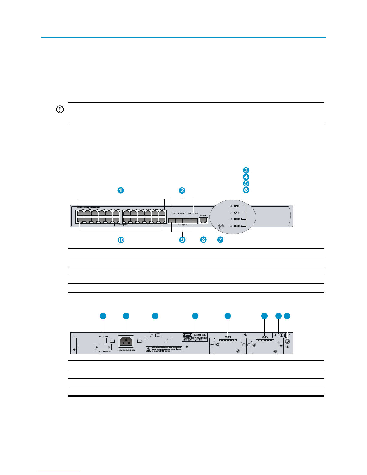
Chassis views
Figure 35 Front view
(1) 10/100/1000 Base-T Ethernet port LEDs
(2) 1000Base-X SFP port LEDs
(3) Status LED (PWR) (4) RPS LED (RPS)
(5) Expansion slot LED (MOD1) (6) Expansion slot LED (MOD2)
(7) PoE/PoE+ LED (Mode) (8) Console port
(9) 1000Base-X SFP ports (10) 10/100/1000 Base-T Ethernet ports
Figure 36 Rear view
(1) DC power receptacle (2) AC power receptacle
(3) OPEN BOOK mark (4) CAUTION mark
(5) 10 GE port slot 1 (6) 10 GE port slot 2
(7) OPEN BOOK mark (8) Grounding screw
1 2 3 4 5 6 7 8
Page 44

40
Technical specifications
Table 12 Technical specifications
Item Specification
Console port One, 9600 bps (default) to 115200 bps
Ethernet port 24 10/100/1000 Base-T autosensing Ethernet ports
SFP port Two 1000Base-X SFP ports
Uplink module slot 2
Memory
• Controller engine—512 MB DDR2
• Switching engine—128 MB DDR2
Flash
• Controller engine—1 GB
• Switching engine—256 MB
Dimensions (H × W × D) (without rubber feet and
mounting brackets)
43.6 × 440 × 429 mm (1.72 × 17.32 × 16.89 in)
Weight 7.2 kg (15.87 lb)
AC power supply
Rated voltage range: 100 VAC to 240 VAC @ 50 Hz or 60
Hz
DC power supply Rated voltage range: –52 VDC to –55 VDC.
PoE power 30 W at most for each port
System power consumption (with no PoE device) 53 W to 90 W
Operating temperature 0°C to 45°C (32°F to 113°F)
Relative humidity (noncondensing) 5% to 95%
Transceiver module specifications
Table 13 SFP-GE-SX-MM850-A specifications
Item Specification
Central wavelength 850 nm
Transmission distance 550 m (1804.46 ft)
Transmission rate 1250 Mbps
Connector type Duplex LC
Fiber mode MMF
Transmit power –9.5 to 0 dBm
Receive sensitivity ≤ –17 dBm
Saturation ≤ –3 dBm
Page 45

41
Table 14 SFP-GE-LX-SM1310-A specifications
Item Specification
Central wavelength 1310 nm
Transmission distance 10 km (6.21 miles)
Transmission rate 1250 Mbps
Connector type Duplex LC
Fiber mode SMF
Transmit power –9.5 to +3 dBm
Receive sensitivity ≤ –20 dBm
Saturation ≤ –3 dBm
Table 15 SFP-GE-LH40-SM1310 specifications
Item Specification
Central wavelength 1310 nm
Transmission distance 40 km (24.86 miles)
Transmission rate 1250 Mbps
Connector type Duplex LC
Fiber mode SMF
Transmit power –2 to +5 dBm
Receive sensitivity ≤ –22 dBm
Saturation ≤ –3 dBm
Table 16 SFP-GE-LH40-SM1550 specifications
Item Specification
Central wavelength 1550 nm
Transmission distance 40 km (24.86 miles)
Transmission rate 1250 Mbps
Connector type Duplex LC
Fiber mode SMF
Transmit power –4 to +1 dBm
Receive sensitivity ≤ –21 dBm
Saturation ≤ –3 dBm
Table 17 SFP-GE-LH70-SM1550 specifications
Item Specification
Central wavelength 1550 nm
Page 46

42
Item Specification
Transmission distance 70 km (43.50 miles)
Transmission rate 1250 Mbps
Connector type Duplex LC
Fiber mode SMF
Transmit power –4 to +5 dBm
Receive sensitivity ≤ –22 dBm
Saturation ≤ –3 dBm
Specifications for transceiver modules applicable to
the HP 830 uplink module
Table 18 XFP-SX-MM850 specifications
Item Specification
Central wavelength 1310 nm
Transmission distance 300 m (984.25 ft)
Transmission rate 10.31 Gbps
Connector type Duplex LC
Fiber mode MMF
Transmit power –7.3 to –1.08 dBm
Receive sensitivity ≤ –11.1 dBm
Saturation ≤ –1 dBm
Table 19 XFP-LX-SM1310 specifications
Item Specification
Central wavelength 1310 nm
Transmission distance 10 km (6.21 miles)
Transmission rate 10.31 Gbps
Connector type Duplex LC
Fiber mode SMF
Transmit power –8.2 to +0.5 dBm
Receive sensitivity ≤ –12.6 dBm
Saturation ≤ 0.5 dBm
Page 47

43
Table 20 XFP-LH40-SM1550-F1 specifications
Item Specification
Central wavelength 1550 nm
Transmission distance 40 km (24.86 miles)
Transmission rate 10 Gbps
Connector type Duplex LC
Fiber mode SMF
Transmit power –1 to +2 dBm
Receive sensitivity ≤ –14 dBm
Saturation ≤ –1 dBm
Page 48
44
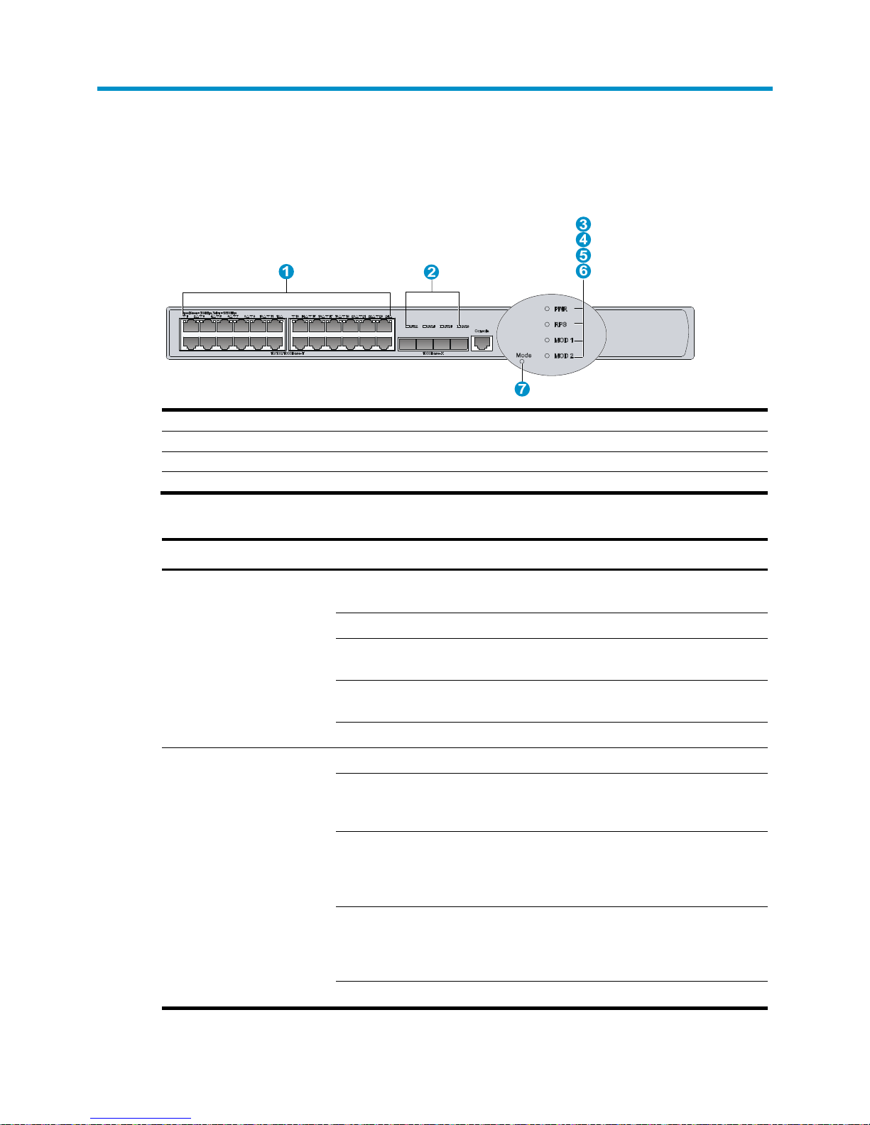
Appendix B LEDs
Figure 37 LEDs
(1) 10/100/1000 Base-T Ethernet port status LEDs (2) 1000Base-X SFP port status LEDs
(3) System status LED (PWR) (4) RPS LED (RPS)
(5) Expansion slot LED (MOD1) (6) Expansion slot LED (MOD2)
(7) PoE/PoE+ LED (Mode)
Table 21 LED description
LED Mark Status Description
Power status
LED
PWR
Steady green
The system is going through the power on self
test (POST) or downloading software.
Flashing green (1 Hz)
The system is operating properly.
Steady red
The system has failed to pass the POST or has
detected a serious fault.
Steady yellow (1 Hz)
At least one port has failed the POST or
detected a minor fault.
Off
No AC input is present.
PoE/PoE+
status LED
Mode
Steady green The PoE/PoE+ is operational.
Flashing green (3 Hz)
PoE/PoE+ supply is not available because the
maximum output power of the port is exceeded
or the remaining power is insufficient.
Steady yellow
The ports cannot provide PoE/PoE+ supply due
to an over-temperature, over-voltage, or
under-voltage protection shutdown of the
PoE/PoE+ system.
Flashing yellow (3 Hz)
At least one port has failed to pass the POST. If
the PoE sub-board is in position, it might be
caused by a UART communication failure or
some other self test failure.
Off No PoE/PoE+ supply.
Page 49

45
LED Mark Status Description
RPS status
LED
RPS
Steady green Both AC and DC inputs are normal.
Steady yellow
The AC input is abnormal or no AC input is
present, while the DC input is normal.
Off No DC input is present.
10/100/10
00 Base-T
Ethernet port
status LED
N/A
Steady green A 1000 Mbps link is present on the port.
Flashing green (33 Hz)
The port is receiving or transmitting data at
1000 Mbps.
Steady yellow A 10/100 Mbps link is present on the port.
Flashing yellow (33 Hz)
The port is receiving or transmitting data at
10/100 Mbps.
Off No link is present on the port.
Gigabit SFP
port status
LED
N/A
Steady green A 1000 Mbps link is present on the port.
Flashing green (33 Hz)
The port is receiving or transmitting data at
1000 Mbps.
Off No link is present on the port.
Expansion
slot LED
MOD1 (or
MOD2)
Steady green An interface module is connected.
Steady yellow
The slot does not support the interface module
installed in it.
Flashing green
The interface module is receiving or
transmitting data.
Flashing yellow The interface module has failed the POST.
Off
No interface module is present in the slot, or the
interface module is not connected.
Page 50
46
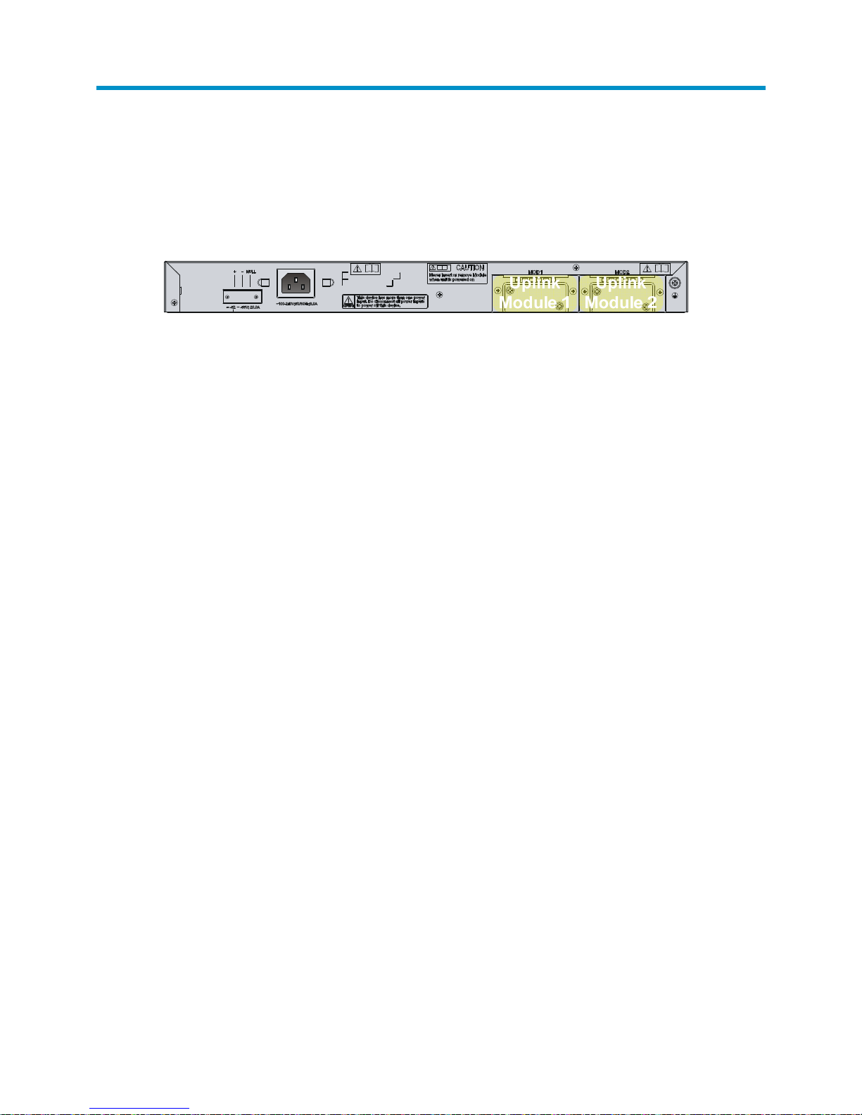
Appendix C Slot arrangement
The HP 830 24-port PoE+ unified wired-WLAN switch provides slots for uplink modules. On the switch,
all fixed ports are located in slot 0.
Figure 38 Slot arrangement for the switch
The switch provides 30 fixed ports numbered GigabitEthernet 1/0/1 through GigabitEthernet 1/0/30,
among which:
• GigabitEthernet 1/0/1 through GigabitEthernet 1/0/24 are 10/100/1000 Base-T Ethernet ports,
with the last part of the port numbers indicated on the front panel.
• GigabitEthernet 1/0/25 through GigabitEthernet 1/0/28 are 1000Base-X SFP fiber ports, with
the last part of the port numbers indicated on the front panel.
• GigabitEthernet 1/0/29 and GigabitEthernet 1/0/30 are internal ports for connecting the
controller engine.
The switch provides two 10 GE interface module slots. The ports on the interface modules installed in
these slots are numbered TenGigabitEthernet 1/1/1 and TenGigabitEthernet 1/2/1.
Page 51

47
Support and other resources
Contacting HP
For worldwide technical support information, see the HP support website:
http://www.hp.com/support
Before contacting HP, collect the following information:
• Product model names and numbers
• Technical support registration number (if applicable)
• Product serial numbers
• Error messages
• Operating system type and revision level
• Detailed questions
Subscription service
HP recommends that you register your product at the Subscriber's Choice for Business website:
http://www.hp.com/go/wwalerts
After registering, you will receive email notification of product enhancements, new driver versions,
firmware updates, and other product resources.
Related information
Documents
To find related documents, browse to the Manuals page of the HP Business Support Center website:
http://www.hp.com/support/manuals
• For related documentation, navigate to the Networking section, and select a networking category.
• For a complete list of acronyms and their definitions, see HP FlexNetwork Technology Acronyms.
Websites
• HP.com http://www.hp.com
• HP Networking http://www.hp.com/go/networking
• HP manuals http://www.hp.com/support/manuals
• HP download drivers and software http://www.hp.com/support/downloads
• HP software depot http://www.software.hp.com
• HP Education http://www.hp.com/learn
Page 52

48
Conventions
This section describes the conventions used in this documentation set.
Command conventions
Convention Description
Boldface Bold text represents commands and keywords that you enter literally as shown.
Italic Italic text represents arguments that you replace with actual values.
[ ] Square brackets enclose syntax choices (keywords or arguments) that are optional.
{ x | y | ... }
Braces enclose a set of required syntax choices separated by vertical bars, from which
you select one.
[ x | y | ... ]
Square brackets enclose a set of optional syntax choices separated by vertical bars, from
which you select one or none.
{ x | y | ... } *
Asterisk-marked braces enclose a set of required syntax choices separated by vertical
bars, from which you select at least one.
[ x | y | ... ] *
Asterisk-marked square brackets enclose optional syntax choices separated by vertical
bars, from which you select one choice, multiple choices, or none.
&<1-n>
The argument or keyword and argument combination before the ampersand (&) sign can
be entered 1 to n times.
# A line that starts with a pound (#) sign is comments.
GUI conventions
Convention Description
Boldface
Window names, button names, field names, and menu items are in bold text. For
example, the New User window appears; click OK.
> Multi-level menus are separated by angle brackets. For example, File > Create > Folder.
Symbols
Convention Description
WARNING
An alert that calls attention to important information that if not understood or followed can
result in personal injury.
CAUTION
An alert that calls attention to important information that if not understood or followed can
result in data loss, data corruption, or damage to hardware or software.
IMPORTANT
An alert that calls attention to essential information.
NOTE
An alert that contains additional or supplementary information.
TIP
An alert that provides helpful information.
Page 53
49
Network topology icons
Represents a generic network device, such as a router, switch, or firewall.
Represents a routing-capable device, such as a router or Layer 3 switch.
Represents a generic switch, such as a Layer 2 or Layer 3 switch, or a router that supports
Layer 2 forwarding and other Layer 2 features.
Represents an access controller, a unified wired-WLAN module, or the switching engine
on a unified wired-WLAN switch.
Represents an access point.
Port numbering in examples
The port numbers in this document are for illustration only and might be unavailable on your device.
Page 54

50
Index
AC
power cord connection, 28
power supply connection to power strip with
lightning protection, 21
troubleshooting power supply failure, 31
Appendix A (Chassis views and technical
specifications), 40
Appendix B (LEDs), 45
Appendix C (Slot arrangement), 47
bracket
front mounting brackets, 11
switch installation (front mounting bracket+rack
shelf), 15
switch installation (front mounting bracket+slide
rails), 16
switch installation (front+rear mounting brackets),
12
built-in fan operational status, 37
cable
console cable connection, 21
Ethernet cable connection, 25
interface cable connection, 21
chassis
cooling and ventilation, 5
HP 830 uplink transceiver module specifications,
43
technical specifications, 41
transceiver module specifications, 41
views, 40
checklist (pre-installation), 7
cleanness (installation site), 5
configuring
exception handling method, 38
connecting
AC power cord, 28
console cable, 21
copper Ethernet port, 25
Ethernet cables, 25
fiber Ethernet port, 25
interface cables, 21
power cord, 28
switch to RPS, 28
console cable connection, 21
controller engine
switch electronic label data display, 36
switch information display, 35
version information, 33
cooling requirements (installation site), 5
CPU usage display, 37
device
management and maintenance, 33
displaying
built-in fan operational status, 37
controller engine version information, 33
exception handling method, 39
power supply operating state, 38
switch CPU usage, 37
switch electronic label data (on controller engine),
36
switch electronic label data (on switching engine),
36
switch hardware information, 33
switch information (on controller engine), 35
switch information (on switching engine), 35
switch memory usage, 37
switch operational statistics, 34
troubleshooting garbled terminal display, 31
troubleshooting no terminal display, 31
dust (installation site), 5
electricity
AC power cord connection, 28
AC power supply connection to power strip, 21
electrical cooling requirements, 5
electromagnetic interference. Use EMI
electrostatic discharge. Use ESD
EMI prevention, 7
ESD prevention, 6
power cord connection, 28
power requirements, 5
safety recommendations, 4
switch connection to RPS, 28
switch grounding, 17
switch grounding with AC power cord (PE wire),
19
switch grounding with buried conductor, 18
switch grounding with strip, 18
switch power on, 29
troubleshooting power supply failure, 31
electronic label data display, 36
EMI prevention, 7
environment
installation site, 4
Page 55

51
site cleanness, 5
site cooling requirements, 5
site dust concentration, 5
site gas saturation, 5
site humidity, 4
site temperature, 4, 6
ESD prevention, 6
Ethernet
cable connection, 25
copper Ethernet port connection, 25
examining installation site, 4
exception handling method, 38, 39
fiber
Ethernet port connection, 25
laser safety recommendations, 4
garbled terminal display, 31
gas (installation site), 5
grounding
EMI prevention, 7
ESD prevention, 6
lightning protection, 7
switch, 17
switch (with AC power cord PE wire), 19
switch (with buried conductor), 18
switch (with strip), 18
hardware
AC power supply connection with lightning
protection, 21
chassis cooling and ventilation, 5
controller engine version information, 33
HP 830 uplink module installation, 26, 27
HP 830 uplink module removal, 26, 28
lightning protector for network port, 20
rack mounting brackets, 11
rack slide rails, 12
switch grounding, 17
switch grounding with AC power cord (PE wire),
19
switch grounding with buried conductor, 18
switch grounding with strip, 18
switch installation, 9
switch power-on, 29
switch rack installation, 11
switch rack installation (front mounting
bracket+rack shelf), 15
switch rack installation (front mounting
bracket+slide rails), 16
switch rack installation (front+rear mounting
brackets), 12
troubleshooting configuration terminal problems,
31
troubleshooting loading failure, 32
workbench switch mount, 10
hardware management/maintenance
built-in fan operational status, 37
chassis technical specifications, 40
chassis views, 40
controller engine version information, 33
exception handling method, 38, 39
HP 830 uplink module transceiver module
specifications, 40
LEDs, 45
power supply operating state, 38
slot arrangement, 47
switch CPU usage display, 37
switch electronic label data display, 36
switch information display, 33, 35
switch memory usage display, 37
switch operational statistics display, 34
switch reboot, 39
switching engine login using OAP, 33
tasks, 33
transceiver module specifications, 40
humidity
installation site requirements, 4
installing
checklist, 7
cooling requirements, 5
EMI prevention, 7
ESD prevention, 6
HP 830 uplink module, 26, 27
installation verification, 29
lightning protection, 7
lightning protector for network port, 20
power requirements, 5
site cleanness, 5
site examination, 4
site humidity, 4
site temperature, 4, 6
switch, 9
switch installation flow, 10
switch on rack, 11
switch on rack (front mounting bracket+rack shelf),
15
switch on rack (front mounting bracket+slide rails),
16
switch on rack (front+rear mounting brackets), 12
interface cable connection, 21
laser safety recommendations, 4
lightning
AC power supply connection to power strip with
lightning protection, 21
Page 56

52
protection, 7
protector for network port, 20
logging in
switching engine login using OAP, 33
maintaing
hardware maintenance, 33
managing
hardware management, 33
memory usage display, 37
module
HP 830 uplink module installation, 26, 27
HP 830 uplink module removal, 26, 28
mounting
front brackets, 11
switch installation (front mounting bracket+rack
shelf), 15
switch installation (front mounting bracket+slide
rails), 16
switch installation (front+rear mounting brackets),
12
workbench switch mount, 10
network
troubleshooting configuration terminal problems,
31
network management
built-in fan operational status display, 37
chassis technical specifications, 40
chassis views, 40
exception handling method, 38, 39
hardware management and maintenance, 33
HP 830 uplink module transceiver module
specifications, 40
LEDs, 45
power supply operating state display, 38
slot arrangement, 47
switch CPU usage display, 37
switch electronic label data (on controller engine),
36
switch electronic label data (on switching engine),
36
switch information (on controller engine), 35
switch information (on switching engine), 35
switch memory usage display, 37
switch operational statistics, 34
switch reboot, 39
transceiver module specifications, 40
troubleshooting switch, 31
no terminal display, 31
OAP
switching engine login, 33
operational statistics display, 34
parameter
terminal parameter setting, 22
password
troubleshooting login password loss, 31
PE
switch grounding with AC power cord (PE wire),
19
port
copper Ethernet port connection, 25
fiber Ethernet port connection, 25
power
cooling requirements, 5
requirements, 5
power supply
AC power cord connection, 28
AC power supply connection to power strip, 21
operating state display, 38
power cord connection, 28
switch connection to RPS, 28
troubleshooting failure, 31
precautions
lightning protector installation, 20
preparing for installation, 3
preventing
EMI prevention, 7
ESD prevention, 6
procedure
configuring exception handling method, 38
connecting AC power cord, 28
connecting AC power supply to power strip with
lightning protection, 21
connecting console cable, 21
connecting copper Ethernet port, 25
connecting Ethernet cables, 25
connecting fiber Ethernet port, 25
connecting interface cables, 21
connecting power cord, 28
connecting switch to RPS, 28
displaying built-in fan operational status, 37
displaying controller engine version information,
33
displaying exception handling method, 39
displaying power supply operating state, 38
displaying switch CPU usage, 37
displaying switch electronic label data (on
controller engine), 36
displaying switch electronic label data (on
switching engine), 36
displaying switch hardware information, 33
displaying switch information (on controller
engine), 35
Page 57

53
displaying switch information (on switching
engine), 35
displaying switch memory usage, 37
displaying switch operational statistics, 34
grounding the switch, 17
grounding the switch with AC power cord (PE wire),
19
grounding the switch with buried conductor, 18
grounding the switch with grounding strip, 18
installing HP 830 uplink module, 26, 27
installing lightning protector for network port, 20
installing switch, 9
installing switch on 19-inch rack, 11
installing switch on 19-inch rack with front
mounting bracket+rack shelf, 15
installing switch on 19-inch rack with front
mounting bracket+slide rails, 16
installing switch on 19-inch rack with front+rear
mounting brackets, 12
logging in to switching engine login using OAP,
33
mounting switch on workbench, 10
powering on switch, 29
rebooting the switch, 39
removing HP 830 uplink module, 26, 28
setting terminal parameters, 22
troubleshooting garbled terminal display, 31
troubleshooting no terminal display, 31
troubleshooting power supply failure, 31
troubleshooting software loading failure, 32
troubleshooting switch, 31
verifying installation, 29
rack
mounting brackets, 11
slide rails, 12
switch installation, 11
switch installation (front mounting bracket+rack
shelf), 15
switch installation (front mounting bracket+slide
rails), 16
switch installation (front+rear mounting brackets),
12
rebooting the switch, 39
removing
HP 830 uplink module, 26, 28
RPS
switch connection to RPS, 28
safety
AC power supply connection to power strip with
lightning protection, 21
caution and warning symbols, 3
electrical safety recommendations, 4
EMI prevention, 7
ESD prevention, 6
general recommendations, 3
installation site cleanness, 5
installation site dust concentration, 5
installation site gas saturation, 5
installation site humidity, 4
installation site temperature, 4, 6
laser safety recommendations, 4
lightning protection, 7
lightning protector for network port, 20
lightning protector installation precautions, 20
power requirements, 5
switch grounding, 17
switch grounding with AC power cord (PE wire),
19
switch grounding with buried conductor, 18
switch grounding with strip, 18
setting terminal parameters, 22
site
cleanness, 5
cooling requirements, 5
dust concentration, 5
examination, 4
gas saturation, 5
humidity, 4
power requirements, 5
temperature, 4, 6
slide rails, 12, 16
software
controller engine version information, 33
troubleshooting loading failure, 32
statistics
switch operational statistics, 34
switch
AC power cord connection, 28
AC power supply connection with lightning
protection, 21
built-in fan operational status, 37
console cable connection, 21
controller engine version information, 33
copper Ethernet port connection, 25
CPU usage display, 37
displaying hardware information, 33
electronic label data display (on controller engine),
36
electronic label data display (on switching engine),
36
Ethernet cable connection, 25
fiber Ethernet port connection, 25
Page 58

54
grounding, 17
grounding with AC power cord (PE wire), 19
grounding with buried conductor, 18
grounding with strip, 18
HP 830 uplink module installation, 26, 27
HP 830 uplink module removal, 26, 28
information display (on controller engine), 35
information display (on switching engine), 35
installation, 9
installation flow, 10
installation verification, 29
interface cable connection, 21
lightning protector for network port, 20
management and maintenance, 33
memory usage display, 37
operational statistics, 34
power cord connection, 28
power supply operating state, 38
powering on, 29
rack installation, 11
rack installation (front mounting bracket+rack
shelf), 15
rack installation (front mounting bracket+slide
rails), 16
rack installation (front+rear mounting brackets), 12
rebooting, 39
RPS connection, 28
switching engine login using OAP, 33
troubleshooting, 31
workbench switch mount, 10
switching engine
switch electronic label data, 36
switch information display, 35
system administration
built-in fan operational status display, 37
exception handling method, 38, 39
power supply operating state display, 38
switch CPU usage display, 37
switch electronic label data display (on controller
engine), 36
switch electronic label data display (on switching
engine), 36
switch information display (on controller engine),
35
switch information display (on switching engine),
35
switch memory usage display, 37
switch operational statistics, 34
switch reboot, 39
switching engine login using OAP, 33
troubleshooting configuration terminal problems,
31
troubleshooting login password loss, 31
temperature
installation site requirements, 4, 6
site cooling requirements, 5
terminal
parameter setting, 22
troubleshooting garbled terminal display, 31
troubleshooting no terminal display, 31
troubleshooting
configuration terminal problems, 31
garbled terminal display, 31
login password loss, 31
no terminal display, 31
power supply failure, 31
software loading failure, 32
switch, 31
ventilation (installation site), 5
verifying installation, 29
version
controller engine version information, 33
workbench switch mount, 10
 Loading...