

Page 1
USER’S MANUAL
7.25 MOTORIZED TREADMILL
MODEL NUMBER: 7.25
USER WEIGHT LIMITATION: 350lbs (160 kgs)
SERVICE NUMBER: 0800-09 72100
SERIAL NUMBER (found on frame):
Page 2

2 7.25 TREADMILL
Precautions:
WARNING: To reduce the risk of burns, fire, electric shock, or injury to persons, read the following important precautions and
information before operating the treadmill. It is the responsibility of the owner to ensure that all users of this treadmill are
adequately informed of all warnings and precautions.
PRECAUTIONS
• Use the treadmill only as described in this manual.
• Place on a level surface, with 6 feet (2 m) of clearance behind it. Do not place the treadmill on any surface that blocks air
openings. To protect the floor or carpet from damage, place a mat under the treadmill.
• When choosing a location for the treadmill make sure that the location and position permit access to a plug.
• Keep the treadmill indoors, away from moisture and dust. Do not put the treadmill in a garage or covered patio, or near
water.
• Do not operate the treadmill where aerosol products are used or where oxygen is being administered.
• Keep children under the age of 12 and pets away from the treadmill at all times.
• The treadmill should not be used by persons weighing more than 350 lbs (160 kgs)
• Never allow more than one person on the treadmill at a time. Wear appropriate exercise clothing when using the treadmill.
Do not wear loose clothing that could become caught in the treadmill. Athletic support clothes are recommended for both
men and women. Always wear athletic shoes. Never use the treadmill with bare feet, wearing only stockings, or in
sandals.
• When connecting the power cord, plug the power cord into a grounded circuit. No other appliance should be on the same
circuit.
• Always straddle the belt and allow it to start moving before stepping onto the belt.
• Always examine your treadmill before using to ensure all parts are in working order.
• Allow the belt to fully stop before dismounting.
• Never insert any object or body parts into any opening.
• Follow the safety information in regards to plugging in your treadmill.
• Keep the power cord away from the incline wheels and do not run the power cord undern eath your treadmill. Do not
operate the treadmill with a damaged or frayed power cord.
• Always unplug the treadmill before cleaning and/or servicing. Service to your treadmill should only be performed by an
authorized service representative, unless authorized and/or instructed by the manufacturer. Failure to follow these
instructions will void the treadmill warranty.
• Never leave the treadmill unattended while it is running.
• The equipment is for Class B (Home Use).
Page 3
www.smoothfitness.com
3
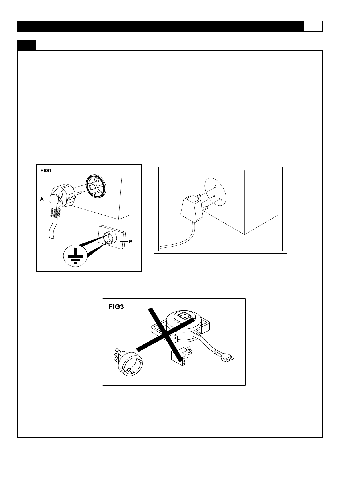
Power Requirements:
IMPROPER CONNECTION OF THE EQUIPMENT GROUNDING CONNECTOR CAN RESULT IN A RISK OF AN ELECTRIC
SHOCK. CHECK WITH A QUALIFIED ELECTRICIAN OR SERVICE MAN IF YOU ARE IN DOUBT AS TO WHETHER THE
PRODUCT IS PROPERLY GROUNDED. DO NOT MODIFY THE PLUG PROVIDED WITH THE PRODUCT, IF IT WILL NOT FIT
THE OUTLET; HAVE A PROPER OUTLET INSTALLED BY A QUALIFIED ELECTRICIAN.
This treadmill can be seriously damaged by sudden voltage changes in your home’s electrical power. Voltage spikes, surges and
noise interference can result from weather conditions or from other appliances being turned on or off. To reduce the possibility of
treadmill damage, always use a surge protector (not included) with your treadmil l.
This treadmill must be grounded to reduce the risk of electrical shock. Grounding provides a path of least resistance for electric
current, should the treadmill malfunction. This treadmill comes with an electrical cord having an equipment-grounding conductor
and a grounding plug. Always plug the power cord into a surge protector, and plug the sur ge protector into an appropriate outlet
that is properly installed and grounded in accordance with all local codes and ordinances.
This product is for use on a nominal 230-volt circuit, and has a grounding plug that looks like the plug il lustrated in the drawing
below.
POWER REQUIREMENTS
Page 4

4 7.25 TREADMILL
Open the boxes:
You are now ready to open the boxes of your new equipment. Make sure to inventory all of the parts that are included in the boxes.
Check the Hardware Comparison Chart for a full count of the number of parts included for this product to be assembled properly. If
you are missing any parts or have any assembly questions call your local Smooth Retailer.
Gather your tools:
Before starting the assembly of your unit, make sure that you have gathered all the necessary tools you ma y require to assemb le
the unit properly. Having all of the necessary equipment at hand will save time and make the assembl y quick and hassle-free.
Clear your work area:
Make sure that you have cleared away a large enough space to properly assemble the unit. Make sure the space is free from
anything that may cause injury during assembly. After the unit is fully assembled, make sure there is a comfortable amount of free
area around the unit for unobstructed operation.
Invite a friend:
Some of the assembly steps may require heavy lifting. It is recommended that you obtain the assistance of another person when
assembling this product.
User Weight Limitation:
Please note that there is a weight limitation for this product. If you weigh more than 350lbs (160kgs) it is not recommended
that you use this product. Serious injury may occur if the user’s weight exceeds the limit shown here. This product is not
intended to support users whose weight exceeds this limit.
Care and maintainence:
1. The safety level can be maintained only if it is examined for damage and wear.
2. Replace the defect components immediately and stop to use the equipment until repair.
3. Always care that you mount on the equipment steady before you start to use the equipment. Dismount from the equipment
4. Always check the easily wear components like pulley ets. To prevent danger.
5. There is an emergency stop to prevent dangers, you can stop the treadmill immediately by actuated the emergency stop for
PREASSEMBLY
after all parts are stop.
emergency dismount.
Page 5
www.smoothfitness.com
A
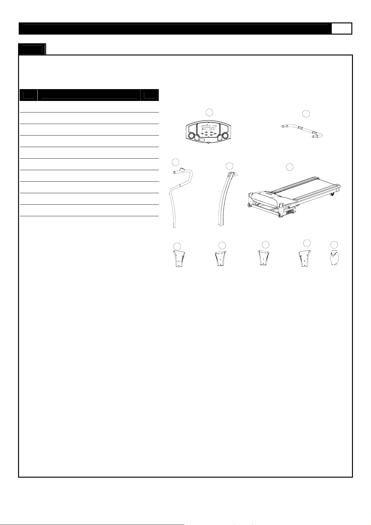
Carton contents:
For your convenience, we have identified the contents of the shipping carton. Please check to make sure you have all of the
components before assembly. This chart is provided to help you identify the components used in the assembly of this product.
CONTENTS CHECKLIST
5
No. Description Qty.
A
Computer
B Front Handlebar Assembly 1
C Handlebar 2
D Upright Assembly 2
E Main Frame Assembly 1
202 Handlebar Lower Cover 2
302 Upright Cover-LL 1
303 Upright Cover -LR 1
304 Upright Cover -RL 1
305 Upright Cover -RR 1
1
C
302
303
B
D
304
E
305
202
Page 6
6 7.25 TREADMILL
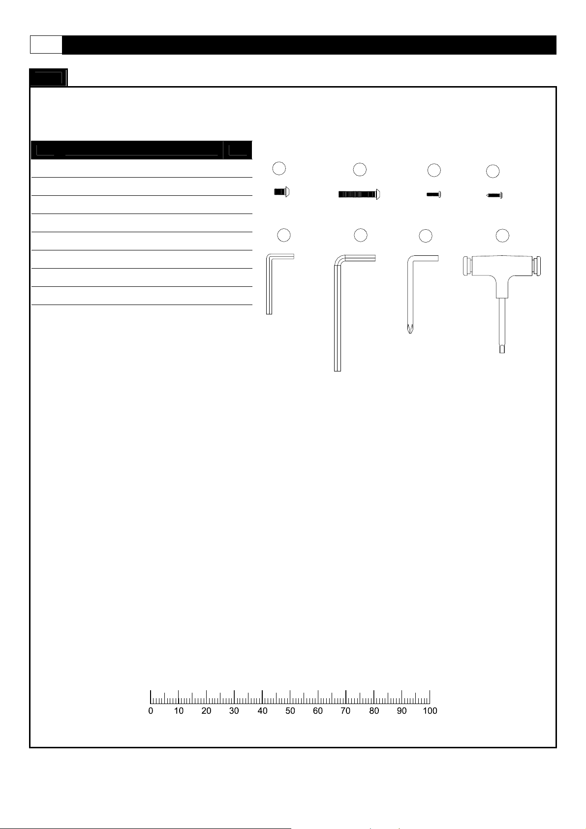
Hardware chart:
For your convenience, we have identified the hardware used in the assembly of this product. This chart is provided to help you
identify those items that may be unfamiliar to you.
HARDWARE COMPARISON CHART
No. Description Qty.
804
M8 x 15mm Bolt
805 M8 x 50mm Bolt 8
806 #8 x 19mm Scre w 8
807 #8 x 19mm Scre w 9
A 5mm Wrench 1
B 8mm Wrench 1
C Wrench 1
D 5mm Allen Wrench 1
2
804
805
A
B
806
CD
807
MILLIMETERS
Page 7

www.smoothfitness.com
7
PARTS LIST
No. Description Qty. Order No.
1 7.25-101
1 7.25-102
1 7.25-103
1 7.25-104
1 7.25-105
1 7.25-106
1 7.25-107
1 7.25-108
1 7.25-109
1 7.25-110
2 7.25-111
1 7.25-112
1 7.25-113
1 7.25-114
2 7.25-115
2 7.25-116
2 7.25-201
2 7.25-202
2 7.25-203
1 7.25-204
1 7.25-205
2 7.25-206
2 7.25-207
2 7.25-208
2 7.25-209
2 7.25-301
1 7.25-302
1 7.25-303
1 7.25-304
1 7.25-305
1 7.25-306
7.25-100
7.25-101
7.25-102
7.25-103
7.25-104
7.25-105
7.25-106
7.25-107
7.25-108
7.25-109
7.25-110
7.25-111
7.25-112
7.25-113
7.25-114
7.25-115
7.25-116
7.25-200
7.25-201
7.25-202
7.25-203
7.25-204
7.25-205
7.25-206
7.25-207
7.25-208
7.25-209
7.25-300
7.25-301
7.25-302
7.25-303
7.25-304
7.25-305
7.25-306
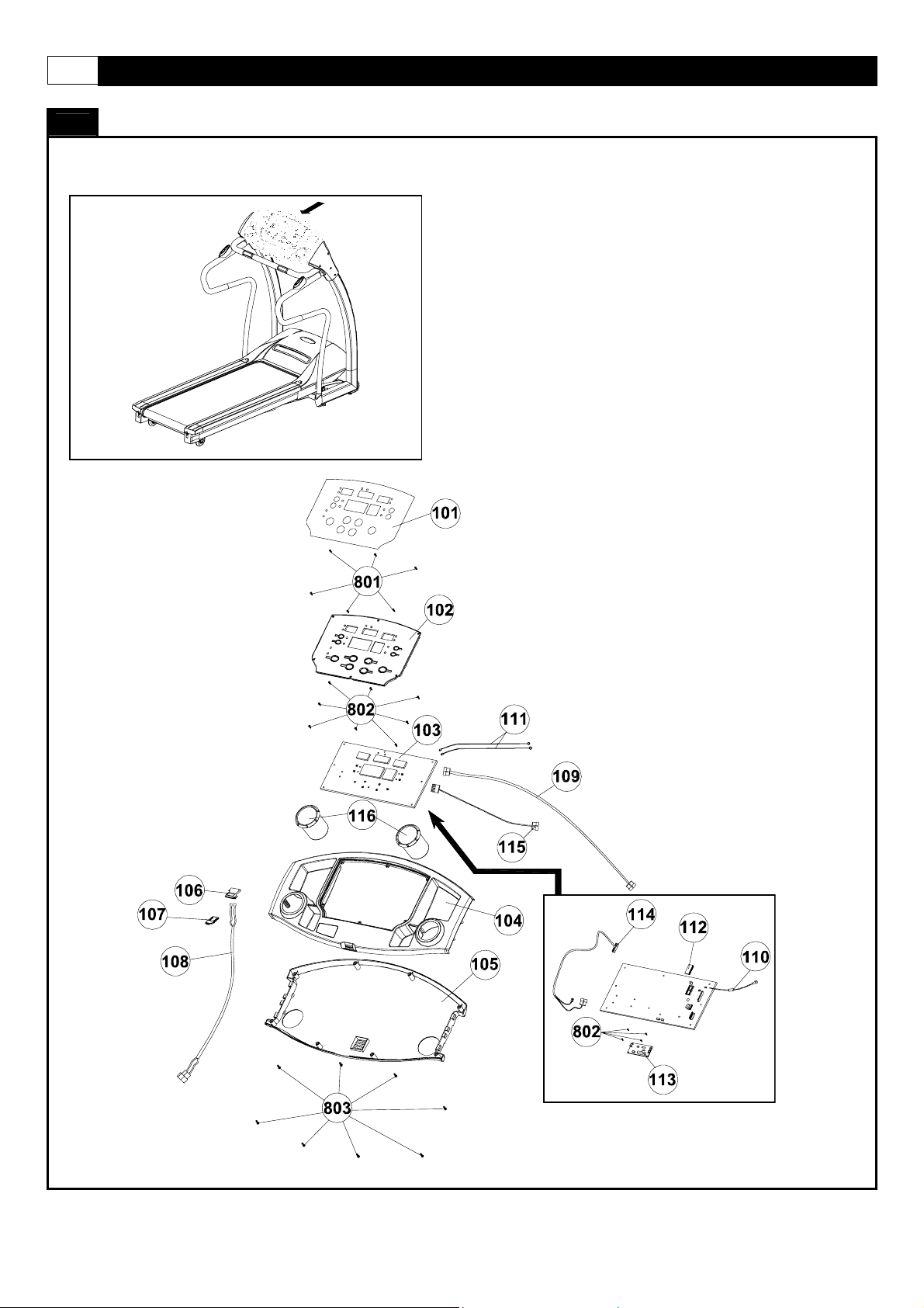
Console Assembly
Overlay
Computer Insert
Console PC Board
Console Housing - Upper
Console Housing - Bottom
Safety key Base
Safety Key
Safety Key Wire - Upper
Computer Wire - Upper
Computer Ground Wire
Hand Pulse Wire - Upper
E - Prom
Motion Control Board
Motion Control Board Wire
Motion Control Sensor Wire
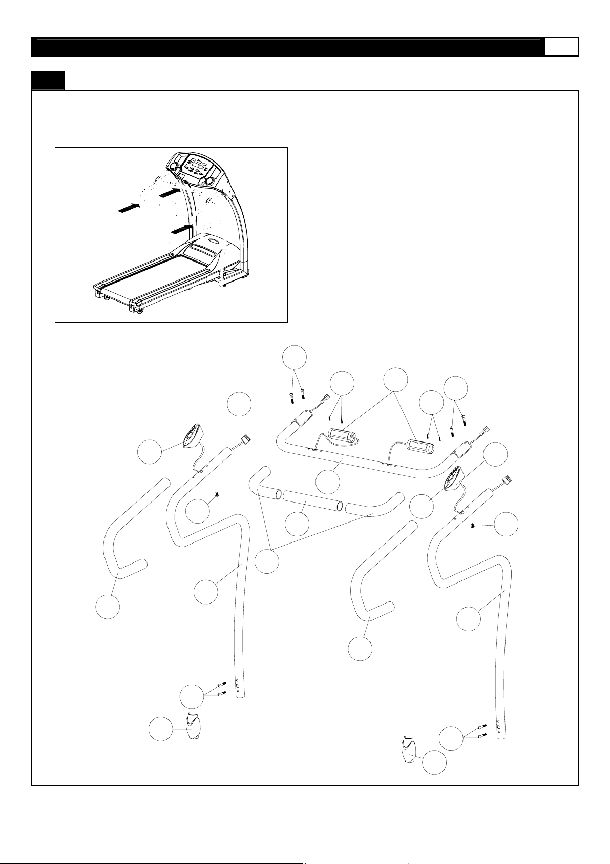
Water Bottle Holder
Handle Bar Upright
Handle Bar Upright Rear End Cap
Handle Bar Upright Foam Grip
Front Handle Bar
Front Handle Bar Foam Grip-Short
Front Handle Bar Foam Grip-Long
Hand Pulse Set
Motion Control
Motion Control Base
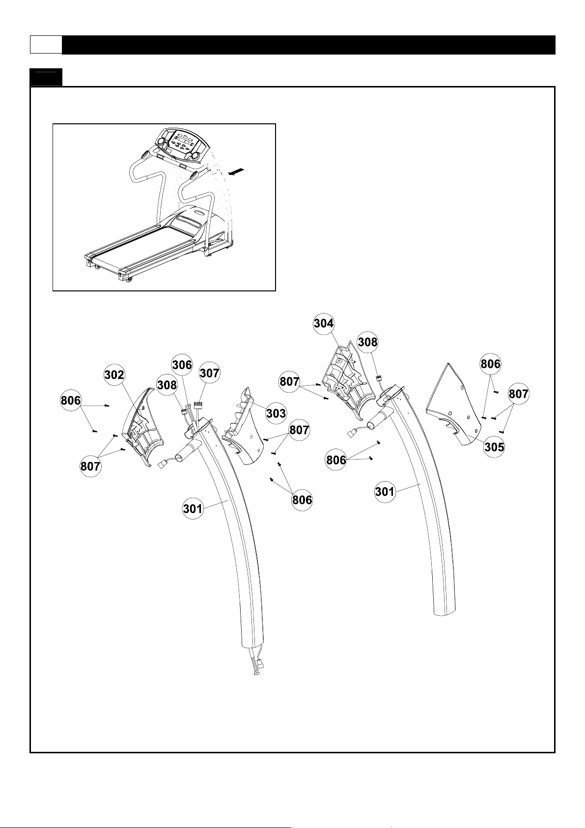
Upright
Upright Cover -LL
Upright Cover -LR
Upright Cover -RL
Upright Cover -RR
Safety Key Wire - Middle
PL-COI-LED17
PL-COU-XT220
PL-COD-XT220
AP-010-01-PL
PL-AP-004
PL-WBI-XT220
IR-HD-XT220-01
PL-BFC-XT220
FO-RO-38X3X950
IR-WD-FHD-XT220
FO-RO-38X3X1108
FO-RO-38X3X1108
EL-HP-001-R038.1
AP-011-01-1
AP-011-02-1
IR-WD-UR-XT220
PL-URCLL-XT220
PL-URCLR-XT220
PL-URCRL-XT220
PL-URCRR-XT220
GM BOM NO.
Page 8

8 7.25 TREADMILL
PARTS LIST
No. Description Qty. Order No.
7.25-307
7.25-308
7.25-400
7.25-401
7.25-402
7.25-403
7.25-404
7.25-405
7.25-406
7.25-407
7.25-408
7.25-409
7.25-410
7.25-411
7.25-412
7.25-413
7.25-414
7.25-415
7.25-416
7.25-417
7.25-418
7.25-419
7.25-420
7.25-421
7.25-422 Plastic Insert
7.25-423
7.25-424
7.25-500
7.25-501
7.25-502
7.25-503
7.25-504
7.25-505
Computer Wire - Upper
Motion Control Sensor Wire - Middle
Base Frame
Safety Key Wire - Lower
Computer Wire -Lower
Power Switch Plate Cover
Power Switch Plate
Power Breaker
Power Switch
Fold UP Support
Foot Locker
Foot Locker Spring
Shock
Fix Bolt Sets
Front Caster
Rubber Cushion
Level Adjuster
Base Frame End Cap
Cushion
Transportation Wheel Bracket
Transportation Wheel Bracket
Spring
Rear Transportation Wheel
Fold Up Support Wheel
Bushing
Motor Hood
Elevation Motor
Elevation Gear Sleeve
Driving Motor
Motor Holder
1 7.25-307
2 7.25-308
1 7.25-401
1 7.25-402
1 7.25-403
1 7.25-404
1 7.25-405
1 7.25-406
1 7.25-407
1 7.25-408
1 7.25-409
1 7.25-410
1 7.25-411
2 7.25-412
2 7.25-413
2 7.25-414
2 7.25-415
2 7.25-416
2 7.25-417
2 7.25-418
1 7.25-419
1 7.25-420
1 7.25-421
1
1 7.25-423
2 7.25-424
1 7.25-501
1 7.25-502
1 7.25-503
1 7.25-504
1 7.25-505
7.25-422 IR-BOLT-06-03-10X16X8.5
GM BOM NO.
IR-WD-BF-XT220
AP-005-01-PL
AP-005-02-PL
AP-005-04-PL
AP-005-03-PL
IR-WD-MF-XT220
AP-004-01-IR
IR-BOLT-07-D2X270
AP-012-O
AP-001
RU-MW-10X100X25
RU-FS-FX-D30X8.5
RU-FS-AD-M8X38.5
RU-FS-FX-101X36X17.5
AP-003-02-IR-2
AP-003-01-IR
RU-MW-D38X22
RU-MW-12X25X25
IR-BOLT-06-03-10X17.5
PL-MCU-XT220
EL-MO-IS25
EL-MO-JS25-O
EL-MO-B1K-1.2HP-4800RPM
AL-TL-01-118
Page 9

www.smoothfitness.com
9
PARTS LIST
No. Description Qty. Order No.
Driving Belt
Motor Control Board
Elevation Control Board
Elevation Support Tube
ELEVATION SUPPORT TUBE COVER - LEFT
MOTOR BOTTOM COVER
DECK FRAME SIDE COVER - LEFT
PLASTIC CLAMP - TOP
PLASTIC CLAMP - BOTTOM
ELEVATION SUPPORT
ELEVATION SUPPORT CAP
DECK RUBBER CUSHION
Rear Vent Cover
ELEVATION SUPPORT TUBE COVER - Right
DECK FRAME SIDE COVER - Right
RUNNING BELT
SIDE RAIL
SIDE RAIL END CAP - LEFT
SIDE RAIL END CAP - Right
RUNNING DECK
DECK FRAME
Front Roller Shaft
Front Roller Tube
Roller Bearing 6202
Rear Roller Shaft
Rear Roller Tube
RUNNING DECK SUPPORT TUBE
DECK FRAME - REAR
Rear Caster
#6 × 12mm Screws
#4 × 6mm Screws
1 7.25-506
1 7.25-507
1 7.25-508
1 7.25-509
1 7.25-510
1 7.25-511
1 7.25-512
2 7.25-513
2 7.25-514
2 7.25-515
2 7.25-516
2 7.25-517
1 7.25-518
1 7.25-519
1 7.25-520
1 7.25-601
2 7.25-602
1 7.25-603
1 7.25-604
1 7.25-605
1 7.25-701
1 7.25-702
1 7.25-703
4 7.25-704
1 7.25-705
1 7.25-706
1 7.25-707
1 7.25-708
2 7.25-413
7.25-801 IR-BOLT-02-03-M3X12X12
12
7.25-802 IR-BOLT-02-03-M2X6X6
12
7.25-506
7.25-507
7.25-508
7.25-509
7.25-510
7.25-511
7.25-512
7.25-513
7.25-514
7.25-515
7.25-516
7.25-517
7.25-518
7.25-519
7.25-520
7.25-600
7.25-601
7.25-602
7.25-603
7.25-604
7.25-605
7.25-700
7.25-701
7.25-702
7.25-703
7.25-704
7.25-705
7.25-706
7.25-707
7.25-708
7.25-413
7.25-800
7.25-801
7.25-802
RU-PB-250J-7
IR-WD-EF-XT220
PL-EFCL-XT220
PL-MCU-XT220
PL-MCSL-XT220
PL-AP-002
PL-AP-003
IR-AP-002
PL-ROC-19.4
PL-MCU-XT220
PL-EFCR-XT220
PL-MCSR-XT220
RU-RB-1.6X493X2760
PL-SRL-XT220
PL-ECL-XT220
PL-ECR-XT220
WO-RB-1195X652X19
IR-WD-RF-XT220
AP-007-04-15X570-IR
AP-007-63.5X117
IR-BR-6202
AP-008-01-15X574-IR
AP-008-63.5
AP-009-01-SQ-22X640
AP-009-02-FO-22.23X3X450
RU-MW-10X100X25
GM BOM NO.
Page 10

10 7.25 TREADMILL
PARTS LIST
No. Description Qty. Order No.
7.25-803
7.25-804
7.25-805
7.25-806
7.25-807
7.25-808
7.25-809
7.25-810
7.25-811
7.25-812
7.25-813
7.25-814
7.25-815
7.25-816
7.25-817
7.25-818
7.25-819
7.25-820
7.25-821
7.25-822
7.25-823
7.25-824
7.25-825
7.25-826
7.25-827
7.25-828
7.25-829
7.25-830
7.25-831
7.25-832
7.25-833
7.25-834
7.25-835
7.25-836
#8 × 12mm Screws
M8 x 15mm Bolt
M8 x 50mm Bolt
#8 x 19mm Screw
#8 x 19mm Screw
M5 × 10mm Screws
#8 × 16 Screws
C Fixed
M10 × 30mm Bolts
Bearing
Washer
Nylon Nut
M8 x 35mm Axle
M14 × 90 Screws
Bearing
M10 × 35mm Screws
#8 × 10mm Screws
#8 × 50mm Screws
M10 × 63mm Bolts
Fixed Block
M8 × 120mm Bolts
Plate Washer
Spring
Nylon Nut
M8 × 20mm Screws
Spring Washer
Washer
M10 × 136mm Screws
M10 × 90mm Screws
M8 × 25mm Screws
Hexagon Nut
M6 × 70mm Bolts
Washer
M10 x 40mm Axle
8 7.25-803
2 7.25-804
8 7.25-805
13 7.25-806
9 7.25-807
3 7.25-808
36 7.25-809
1 7.25-810
1 7.25-811
1 7.25-812
8 7.25-813
7 7.25-814
1 7.25-815
2 7.25-816
4 7.25-817
10 7.25-818
7 7.25-819
2 7.25-820
1 7.25-821
8 7.25-822
1 7.25-823
2 7.25-824
1 7.25-825
1 7.25-826
6 7.25-827
10 7.25-828
2 7.25-829
1 7.25-830
1 7.25-831
8 7.25-832
8 7.25-833
3 7.25-834
3 7.25-835
1 7.25-836
GM BOM NO.
IR-BOLT-02-03-M4X12-S
IR-BOLT-01-08-M8X15X15
IR-BOLT-01-01-M8X50X50
IR-BOLT-02-03-M4X19-S
IR-BOLT-02-03-M4X15-S
IR-BOLT-01-01-M5X10X10
IR-BOLT-02-03-M4X15
IR-BOLT-01-10-M10X30
IR-BOLT-06-02-7X11
IR-BOLT-05-01-4.5X10X1
IR-BOLT-03-02-M10X16X10
IR-BOLT-01-10-M14X90X29
IR-BOLT-06-02-5X6X10
IR-BOLT-01-08-M10X35X15
IR-BOLT-02-03-M4X10-S
IR-BOLT-02-03-M4X50
IR-BOLT-01-10-10X61
PL-AP-001
IR-BOLT-01-09-M8X120X35
IR-BOLT-05-01-8X40X2
RU-BS-8X22.5X14
IR-BOLT-03-02-M8X14X8
IR-BOLT-01-08-M8X20X20
IR-BOLT-05-01-8X14X2
IR-BOLT-05-01-8X16X3
IR-BOLT-01-06-M10X136X13
IR-BOLT-01-06-M10X90X13
IR-BOLT-01-02-M8X25X25
IR-BOLT-04-01-M8X13X6.5
IR-BOLT-01-05-M6X70X70
IR-BOLT-05-01-6X13X1
IR-BOLT-01-10-M10X40X4
Page 11

www.smoothfitness.com
11
PARTS LIST
No. Description Qty. Order No.
7.25-837
7.25-838
7.25-839
7.25-840
7.25-841
7.25-842
C Fixed 2 7.25-837 IR-BOLT-06-03-M10C
M10 × 43mm Bolts
Cushion Pad 8 7.25-839 AP-006
M10 × 40mm Screws
M6 × 10mm Screws
M10 × 52mm Screws
2 7.25-838 IR-BOLT-01-10-M10X42
1 7.25-840 IR-BOLT-01-05-M10X40X15
2 7.25-841 IR-BOLT-01-01-M6X10X10
1 7.25-842 IR-BOLT-01-06-M10X52X30
GM BOM NO.
Page 12
12 7.25 TREADMILL
A MAJORITY OF THE PARTS SHOWN HERE HAVE BEEN PRE-ASSEMBLED AT THE FACTORY.
PARTS DIAGRAM
Page 13
www.smoothfitness.com
A MAJORITY OF THE PARTS SHOWN HERE HAVE BEEN PRE-ASSEMBLED AT THE FACTORY.
PARTS DIAGRAM
13
203
209
804
201
208
206
805
205
801
204
207
805
801
209
208
804
201
203
202
805
805
202
Page 14
14 7.25 TREADMILL
A MAJORITY OF THE PARTS SHOWN HERE HAVE BEEN PRE-ASSEMBLED AT THE FACTORY.
PARTS DIAGRAM
Page 15

www.smoothfitness.com
PARTS DIAGRAM
A MAJORITY OF THE PARTS SHOWN HERE HAVE BEEN PRE-ASSEMBLED AT THE FACTORY.
15
422
811
812
423
407
406
808
408
405
409
837
808
424
411
416
410
415
813
809
402
404
420
417
418
403
817
414
419
412
809
421
814
413
813
809
842
816
818
412
413
817
401
414
809
415
810
815
Page 16

16 7.25 TREADMILL
PARTS DIAGRAM
A MAJORITY OF THE PARTS SHOWN HERE HAVE BEEN PRE-ASSEMBLED AT THE FACTORY.
518
501
513
514
515
809
516
512
819
819
820
508
507
510
831
814
821
503
504
814
502
506
505
820
823
509
824
829
830
825
828
519
513
824
827
809
826
814
516
819
827
511
517
809
806
514
515
827
520
Page 17

www.smoothfitness.com
PARTS DIAGRAM
A MAJORITY OF THE PARTS SHOWN HERE HAVE BEEN PRE-ASSEMBLED AT THE FACTORY.
602
17
603
809
601
602
832
604
605
822
818
Page 18

18 7.25 TREADMILL
PARTS DIAGRAM
A MAJORITY OF THE PARTS SHOWN HERE HAVE BEEN PRE-ASSEMBLED AT THE FACTORY.
704
834
706
835
705
708
707
413
838
841
814
704
836
422
828
833
704
703
835
837
834
839
828
840
833
702
814
704
701
828
833
828
833
Page 19

www.smoothfitness.com
ASSEMBLY
STEP 1:
Remove your treadmill from the carton and place it on the floor in an open area.
Connect the Middle Section Computer Wire (307) to the Lower Section Computer W ire
(403) and the Middle Section Safety Key Wire (306) to the Lower Section Safety Key Wire
(402). Insert any extra cable length into the Left Upright (301).
Insert the Left and Right Uprights (301) into the Base Frame (401).
19
301
301
306
307
403
402
401
Page 20

20 7.25 TREADMILL
ASSEMBLY
STEP 2:
First connect the Motion Control Wire Middle Section (308) to Motion Control Wire
Lower Section (208) as shown.
Insert the Handlebar (201) into the Upright Tube (301) and secure using two M8 x
15mm Bolts (804), Four M8 x 50mm Bolts (805) and attach Handlebar Lower Cover
(202) to Base Frame (401).
308
208
804
805
X2
X4
301
201
805
804
301
202
201
804
805
202
Page 21

STEP 3:
Attach the Front Handlebar (204) on the Upright Tube (301) and secure using four
M8 x 50mm Bolts (805).
ASSEMBLY
805
204
www.smoothfitness.com
805
X4
21
301
301
Page 22

22 7.25 TREADMILL
STEP 4:
Connect the Upper Section Computer Wire (109) to the Middle Section Computer
Wire (308) and the Upper Section Safety Key Wire (108) to the Middle Section
Safety Key Wire (307).
Connect the Upper Section Hand Pulse Wires (111) to Lower Section
Wires (207) and Upper Section Motion Control Wires (115) to Lower
Section Wires (308) for each side.
Attach the Upright Cover RL (304) and Upright Cover LR (303).
using four #8 x 19mm Screws (806) and four #8 x 19mm Metal Screws (807).
Fix the console (100) with 4 screws (806
ASSEMBLY
Secure
) to upright covers (304-305).
806
807
X4
x4
Page 23

www.smoothfitness.com
ASSEMBLY
STEP 5:
First Fix the Ground Wire (110) to the Upright Tube (301) and secure using one #8 x 19mm Metal
Screws (807).
Attach the Upright Cover RR (305) and the Upright Cover LL (302) to the Upright Tube (301).
Secure using four #8 x 19mm Screws (806) and four #8 x 19mm Metal Screws (807).
806
807
x4
X5
23
301
807
Page 24

24 7.25 TREADMILL
STEP 6:
Secure by tightening the Fix Bolts Sets (412). The Fix Bolts Sets (412) are pre-assembled to the Base Frame
(401) at the factory.
ASSEMBLY
Page 25

www.smoothfitness.com
25
FOLLOW THESE INSTRUCTIONS TO LEVEL YOUR TREADMILL:
An uneven floor or improper stabilizer level can cause the treadmill to wobble during use as well as the incline adjustment to
function incorrectly. Please follow the procedure described below to make sure the treadmill stabilizer is adjusted correctly prior to
use. You may need the assistance of another person to perform this adjustment.
First locate the two adjustable stabilizers under the base frame. Then simply rotate them in or out to adjust the level of
the treadmill. When properly adjusted the treadmill should sit firmly on both stabilizers and all cushions.
STABILIZER ADJUSTMENT
Locate the two adjustable stabilizers under the base frame.
Treadmill should sit firmly on both stabilizers and all cushions.
Page 26

26 7.25 TREADMILL
How to fold treadmill:
Treadmill can be folded for space saving storage. To do this follow instructions her e:
FOLDING INSTRUCTIONS
Lift the deck carefully from rear
K
IC
CL
You will hear a click sound when the lock engages.
Page 27

www.smoothfitness.com
How to unfold treadmill:
To unfold treadmill for use follow the instructions here:
UNFOLDING INSTRUCTIONS
Release Lever
27
Lift the deck froTip the release lever with your foot…portation wheels.
… and carefully let down the deck
Page 28

28 7.25 TREADMILL
TRANSPORT INSTRUCTIONS:
To roll away for storage simply grab the rear deck, lift slightly and roll to desired location.
TRANSPORT INSTRUCTIONS
Lift the deck from the rear so that the treadmill rests on the front transportation wheels.
Roll to a desired location.
Page 29

www.smoothfitness.com
29
A
B
C
D
E
F
G
P
H
I
J
K
L
M
N
O
Time/Distance/Height A B Speed/Calories/Weight
Mode C D Motion Control On/Off
Metric/English E F Stop/Enter
Incline Up/Down G H Speed Profile
Incline Profile I K Pulse/Incline/Age
Custom Program Save K L Fitness-Test
Preset Programs M N Start
Speed Up/Down O P Safety Key
BUTTON FUNCTIONS:
START
Press to start exercise at an initial speed of 0.5 mph / 0.8 km/h.
STOP / ENTER
a. Press to confirm program and preset function values during setting mode.
b. Press to run setting procedure before pressing the START button.
c. Press to stop exercise during workout time.
Scan/Hold
Switches the LED window display information:
a. The computer has a factory setting that auto switches between TIME, SPEED, PULSE, DISTANCE, CALORIES and INCLINE
LEVEL. Each value will be displayed for 10 seconds.
b. Press the MODE button once to display only TIME, SPEED and PULSE.
c. Press the MODE button a 2
d. Press the MODE button a 3
nd
time to display only DISTANCE, CALORIES and INCLINE LEVEL.
rd
time return to the auto switch display.
MOTION CONTROL
Press to activate the MOTION CONTROL function. Follow the MOTION CONTROL operating instructions for details.
Page 30

30 7.25 TREADMILL
COMPUTER OPERATION
CUSTOM PROGRAM
When selecting the custom program from C1 to C3, follow the instructions to press this button and save the program as your own
custom workout program. Follow the C1-C3 CUSTOM PROGRAM operating instructions for details.
FITNESS-TEST
Press to start the Fitness-Test function to test your physical condition during a workout. Follow the Fitness-Test operating
instructions for details.
SPEED UP / DOWN
a. Press to increase/decrease exercise speed by 0.1mph / km/h.
b. Hold the button to rapidly increase/decrease speed by 0.5mph / km/h per second. Release the button to stop the function.
c. Press to select programs and preset related function value.
INCLINE UP / DOWN
a. Press up or down to change incline level.
IMPORTANT INFORMATION:
SAFETY KEY
The safety key must be inserted into the slot on the console in order to operate the treadmill. Always insert the safety key and
attach the clip to your clothing at your waist before beginning your workout. If you should encounter problems and ne ed to stop the
motor quickly, simply pull on the cord to disengage the safety key from the console. To continue operation first turn the power
switch to OFF and set the speed controller to stop. Next turn the power switch to ON and reinsert the safety key into the console.
ENGLISH / METRIC CONVERSION
The treadmill computer display can show METRIC and ENGLISH information. This should be preset for your area by the factory.
However, in case the treadmill needs to be converted between METRIC and ENGLISH readout, please follo w the proc edure below:
Set the POWER SWITCH to ON. Press the START button on the computer and hold it. Insert the SAFETY KEY then release the
START button. The computer will sound one short beep. Press the START button to switch between ENGLISH and METRIC and
press STOP/ENTER button to confirm the setting. The computer will sound a long beep and will return to the POWER ON mode
with the new setting.
POWER ON
Set the POWER SWITCH, located on the base frame, to ON and
insert the SAFETY KEY. All LED windows light up with a short
beep sound. “U1” displays in the LAP window,
SPEED/CALORIES displays the user weight factory setting
value “150”lbs or “68”kg, TIME/DISTANCE displays the user
height factory setting value “67”inches or “170”cm, and
PULSE/INCLINE displays the user age factory setting value
“35”. If there is any user information that has been input and
saved, all LED windows will display the information from the last
input user information. If no further button inputs are made
within 3 minutes, the computer will enter the SLEEP MODE.
Press any button to return to the POWER ON mode.
SLEEP / DISPLAY MODE
When the power is ON the computer will automatically enter SLEEP MODE if it is left idle for 3 minutes without receiving any input.
Press any button to return to POWER ON status when the computer is in the SLEEP MODE.
To cancel the SLEEP MODE feature using the DISPLAY MODE and always keep the console display on, pull out the safet y key,
press and hold the SPEED UP and DOWN buttons, insert the safety key to power on the treadmill. After one short beep sound the
PULSE LED window will show “1”. Press the START button then TIME LED window will show “ON” (SLEEP MODE feature on) or
“OFF” (SLEEP MODE feature off). Press the INCLINE UP and DOWN buttons to switch between “ON” and “OFF” then press
STOP/ENTER to save the setting and return to POWER ON mode.
Page 31

www.smoothfitness.com
31
COMPUTER OPERATION
OPERATING INSTRUCTIONS:
QUICK START
When the treadmill is in POWER ON status, press the START button to activate the QUICK START program. The SPEED LED will
count down 3 seconds with 3 short beep sounds then start from 0.5 mph / 0.8 km/h. Press the SPEED UP/DOWN buttons to
change the speed. Press the INCLINE UP/DOWN buttons to elevate the treadmill. The TIME, CALORIES and DISTANCE will
count up from 0.
PAUSE / STOP
During the workout press the STOP/ENTER button once to pause the treadmill. Press the STOP/ENTER button twice to delete all
workout data and return to POWER ON status.
COOL DOWN
After completion of each program the TIME LED window will
show “COOL” and blink then start a one-minute cool down
procedure. Time counts down from 01:00 to 00:00 and speed
stays at 2 mph / 3.2 km/h and the incline level stays at level 0.
After the time counts down to 00:00 the belt stops and returns to
PAUSE/STOP status. Press the STOP/ENTER button to return
to POWER ON status. To escape the cool down procedure
press the STOP/ENTER button once anytime during the process
to enter the PAUSE/STOP status and press the STOP/ENTER
button again to enter the POWER ON status.
FITNESS-TEST
The Fitness-Test function is the feature to let the user test their physical condition during a workout. The fitness rating is determined
by measuring how quickly the user’s pulse slows down and with that measuring the user physical condition. The faster the pulse
slows down, the better the user’s physical condition. User’s can record their fitness rating to use for reference. To start the FitnessTest, press the “Fitness-Test ” button toward the end of a workout (while your pulse is still under trainings load). The treadmill will
enter the PAUSE/STOP status. Put both hands on the hand pulse sensors within 10 seconds (for models equipped with a chest belt
pulse transmitter, keep the chest belt on, no need to hold the hand pulse). The pulse receiver will scan and detect the user’s pulse
in 10 seconds and enter the Fitness-Test function. TIME counts down from 01:00 to 00:00. After the count-down the SPEED LED
window will show the Fitness rating (1-6). The lower the number the better your fitness. Record the rating for future comparison.
After completion of the Fitness-Test (1 minute) the training can be resumed by pressing the START button.
During the Fitness-Test, if you want to stop the function and stop workout, press the STOP/ENTER button and return to POWER ON
status.
During the Fitness-Test, if you want to continue the previous program, press the START button to continue the previous program.
After pressing the Fitness-Test button, if the pulse receiver fails to scan and receive the user’s pulse the computer will sta y at
PAUSE/STOP status. Press the STOP/ENTER button to return to POWER ON status or press the START button to continue the
previous program.
The Fitness-Test cannot be activated while in the COOL DOWN
COMPUTER OPERATION:
Before selecting the program, a user ID needs to be selected. For the first time user, please set up the user information and assign
your USER ID from U 1 to U 9. Press the SPEED UP/DOWN buttons to select the user ID when the computer is in POWER ON
mode.
SET UP USER INFORMATION
After selecting the USER ID the SPEED LED window will show the previous setting for user body weight or the factory setting value
of “150” lbs or “68” kg and be blinking. Press the SPEED UP/DOWN buttons to set the user height then press the STOP/ENTER
button to confirm and save.
After setting the user height the TIME LED window will show the previous setting for user height or the factory setting value of “67”
inches or “170” cm and be blinking. Press the SPEED UP/DOWN buttons to set the user body weight then press the STOP/ENTER
button to confirm and save.
After setting the user weight the PULSE LED window will show the previous setting for user age or the factory setting value of “35”
and be blinking. Press the SPEED UP/DWON buttons to set the user age then press the STOP/ENTER button to confirm and save.
Page 32

32 7.25 TREADMILL
COMPUTER OPERATION
SELECT OPERATING PROGRAM
After completing the user information set up the SPEED PROFILE LED window will show “P1”. Press the SPEED UP/DOWN
buttons to select a P1 – P8 program or C1-C3 user program then press the STOP/ENTER button to confirm. Prior to starting the
selected program, follow the procedure to operate the different programs as below:
PROGRAM 1 – TARGET TIME
If P1 is selected, the TIME LED window shows “30:00” as the
preset workout time. Press the SPEED UP/DOWN buttons to
set target workout time. Press the STOP/ENTER button to save
the target time and press the START button to start the
program. Speed starts from 2.0 mph / 3.2 km/h. Incline starts
from level 0. Press the SPEED UP/DOWN buttons to adjust the
speed and press the INCLINE UP/DOWN buttons to adjust the
incline level. TIME counts down from the target time to zero.
PROGRAM 2 – TARGET DISTANCE
If P2 is selected, the DISTANCE LED window shows “0.00”.
Press the SPEED UP/DOWN buttons to set the target distance.
Press the STOP/ENTER button to save the target distance and
press the START button to start the program. Speed starts
from 2.0 mph /3.2 km/h. Incline starts from level 0. Press the
SPEED UP/DOWN buttons to adjust the speed and press the
INCLINE UP/DOWN buttons to adjust the incline level.
DISTANCE counts down from the target distance.
PROGRAM 3 – TARGET CALORIES
If P3 is selected, the CALORIES LED window shows “0”. Press
the SPEED UP/DOWN buttons to set the target calories. Press
the STOP/ENTER button to save the target calories and press
the START button to start the program. Speed starts from 2.0
mph /3.2 km/h. Incline starts from level 0. Press the SPEED
UP/DOWN buttons to adjust the speed and press the INCLINE
UP/DOWN buttons to adjust the incline level. CALORIES count
down from the target calories.
Page 33

COMPUTER OPERATION
www.smoothfitness.com
33
PROGRAM 4 – INTERVAL INCLINE
If P4 is selected, the TIME LED window shows the factory
setting value “24:00” and the PULSE/INCLINE LED window
shows a blinking “L 1”. Press the SPEED UP/DOWN buttons
to select the intensity of workout from L1 to L12 then press
the STOP/ENTER button. The TME LED window shows a
blinking “24:00”. Press the SPEED UP/DOWN buttons to
adjust the workout time. Every adjustable section is 4
minutes. Press the STOP/ENTER button to save the setting
then press the START button to start the program. The
incline level will be changed by the computer following the
factory setting pattern. Press the SPEED UP/DOWN buttons
to adjust the speed.
PROGRAM 5 – INTERVAL SPEED
If P5 is selected, the TIME LED window shows the factory
setting value “24:00” and the PULSE/INCLINE LED window
shows a blinking “L 1”. Press the SPEED UP/DOWN buttons
to select the intensity of workout from L1 to L12 then press
the STOP/ENTER button. The TME LED window shows a
blinking “24:00”. Press the SPEED UP/DOWN buttons to
adjust the workout time. Every adjustable section is 4
minutes. Press the STOP/ENTER button to save the setting
then press the START button to start the program. The
speed will be changed by the computer following the factor y
setting pattern. Press the INCLINE UP/DOWN buttons to
adjust the incline level.
PROGRAM 6 – WEIGHT LOST
If P6 is selected, the TIME LED window shows the factory
setting value “30:00” and the PULSE/INCLINE LED window
shows a blinking “L 1”. Press the SPEED UP/DOWN buttons
to select the intensity of workout from L1 to L12 then press
the STOP/ENTER button. The TME LED window shows a
blinking “30:00”. Press the SPEED UP/DOWN buttons to
adjust the workout time. Every adjustable section is 5
minutes. Press the STOP/ENTER button to save the setting
then press the START button to start the program. The
speed and incline level will be changed by the computer
following the factory setting pattern.
PROGRAM 7 – 5K SELF LEARING AND COMPETITION
If P7 is selected, the DISTANCE LED window shows “3”
miles or “5” km. Press the START button to start the
program. Press the SPEED UP/DOWN buttons to adjust the
speed and press the INCLINE UP/DOWN buttons to adjust
the incline level.
Page 34

34 7.25 TREADMILL
COMPUTER OPERATION
PROGRAM 8 – HEART RATE CONTROL
If P8 is selected, the TIME LED window shows the factory
setting value of “60:00” and is blinking. Press the SPEED
UP/DOWN buttons to adjust the workout time. Every
adjustable section equals 3 minutes. Press the
STOP/ENTER button to save the setting then the TARGET
HEART RATE displays in the PULSE LED window and is
blinking. The factory TARGET HEART RATE setting is
based on 85% of the maximum user heart rate. The
maximum user heart rate is calculated using the
formula: 220 minus the user age. As an example, for age
35 the maximum user heart rate should be 185 and 85%
of the maximum user heart rate will be 157. Press the
SPEED UP/DOWN buttons to adjust the TARGET HEART
RATE according to your own physical condition or your
doctor’s instruction then press the STOP/ENTER buttons to
save the setting.
Press the START button to start the three minute WARM UP program. Speed starts from 2.0 mph /3.2 km/h and the
INCLINE LEVEL starts from level 0. Keep your hand on the hand pulse grips all the time during this workout in order to
monitor your pulse correctly. During the program, if the heart rate monitor fails to sense the user’s pulse you will see “P”
blinking in the PULSE LED window. If the heart rate monitor senses the pulse properly the PULSE DOT LED blinks and the
correct pulse readout shows on the PULSE LED window. The computer will sense the user’s pulse every 30 seconds.
During the warm up program you can press the STOP/ENTER button to pause or stop the program or press the START
button to re-start the program. Other buttons will not react during this warm up process.
During the warm up program, if the heart rate monitor fails to sense the user’s pulse (the PULSE LED will display a blinking
“P”) the computer will not change the speed. If the heart rate monitor senses the user’s pulse properly but the actual user’s
pulse does not reach 65% of the max. heart rate (( 220-age) x 65%) then the speed will increase by 0.5 mph /0.8 km/h every
30 seconds. If the actual pulse reaches 65% of the max. heart rate the speed will remain unchanged. If the actual pulse
remains at 65% of the max. heart rate for more than one minute the speed will be maintained until the warm up program is
finished.
If the actual user’s pulse fails to reach 65% of the max. heart rate within the first 3 minutes of the warm up program, the
computer will continue a second 3 minute warm up program. All workout information continues to count up and the timer
counts down from 3:00. During the second 3 minute warm up the computer will change the incline level instead of the speed.
If the heart rate monitor fails to sense the user’s pulse (the PULSE LED will display a blinking “P”) the computer will not
change the incline level. If heart rate monitor senses the user’s pulse properly but the actual user’s puls e does not reach
65% of the max. heart rate (( 220-age) x 65%) then the incline level will be increased by 1 level every 30 seconds. If the
actual pulse reaches 65% of the max. heart rate the incline level will remain unchanged. If the actual pulse remains at 65%
of the max. heart rate for more than one minute the speed will be maintained until the warm up program is finished.
If the actual user’s pulse fails to reach 65% of the max. heart rate within the second 3 minute warm up, the computer will
continue a third 3 minute warm up program. All workout information continues to count up and the timer counts down from
3:00. During the third 3 minute warm up both speed and incline remain unchanged regardless the actual pulse. If the time
counts down to 0 and 65% of the max. heart rate still cannot be achieved then the TIME LED will show “FAIL” and the
program will stop and return to POWER ON status.
After the warm up program is completed, if the actual pulse reaches 65% of the max. heart rate, the computer will enter the
HEART RATE CONTROL program. TIME counts down from the previous setting. Distance and Calories continue to count
up from the warm up program. During the HEART RATE CONTRO L program the heart rate monitor will sense the actual
user’s pulse every 30 seconds. If the actual user’s pulse does not reach 85% of the max. heart rate then the incline le vel will
be increased by 1 level every 30 seconds. If the actual user’s pulse reaches 85% of the max. heart rate then the treadmill
performance will be remain unchanged. If the actual user’s pulse is greater than 85% o f the max. heart rate, the incl ine level
will be reduced by 1 level. Speed will remain unchanged until the incline level increases up to 15% or down to 0%. If the
incline level is up to 15% and 85% of the max. heart rate still cannot be reached then the speed will be increas ed by 0.5 mph
/0.8 km/h every 30 seconds. If the incline level decreases down to 0% and the actual user’s pulse is still greater than 85% of
the max. heart rate then the speed will be decreased by 0.5 mph /0.8 km/h every 30 seconds.
If the actual user’s pulse remains above 85% of the max. heart rate for more than 3 minutes the HEART RATE CONTROL
program will shut down and enter a one minute COOL DOWN program.
Page 35

www.smoothfitness.com
COMPUTER OPERATION
When the TIME counts down to 0, the HEART RATE CONTROL program is completed and the computer enters a oneminute COOL DOWN program.
After the COOL DOWN program the computer will return to POWER ON status.
The purpose of HEART RATE CONTROL program is to keep the user’s pulse between 65% of the max. heart rate and 85%
of the max. heart rate to achieve the most efficient workout result.
C1 – C3 CUSTOM PROGRAM (USER PROGRAM)
The program can allow 3 custom programs to be set by users and store the settings for repeated workouts. The maximum
workout time of each user program is 60 minutes. During the workout after the TIME counts up to 60:00, the treadmill will
start a one-minute cool down procedure automatically. To set and store the user programs, please follow the procedure
below:
SET AND SAVE THE USER PROGRAM
Select between C1 to C3 and press the STOP/ENTER button
to enter the user program then press the START button.
Speed starts at 3.2 km/h / 2.0 mph and the incline level starts
at level 0. Each section of SPEED/INCLINE is one minute.
Press the SPEED UP/DOWN buttons to change the speed
and press the INCLINE UP/DOWN buttons to change the
incline during the workout. The computer will take the actual
speed and incline level at the last second of each minute
section and temporary save as the speed and incline l evel of
that minute section. Continue the workout until you want to
stop. Press the STOP/ENTER button to enter the oneminute cool down session. The computer will automatically
enter the save program status after the one-minute cool
down session. If you want to skip the cool down procedure,
press the STOP/ENTER button to enter the save program
status.
When the computer is in save program status, the “CUSTOM SAVE” button will blink slowly. Press the button to save this
program or press the STOP/ENTER button to delete the program and return to POWER ON status.
EDIT PREVIOUS SAVED PROGRAM
Edit the Speed and Incline without extending the previously saved workout time:
Simply press the SPEED UP/DOWN and INCLINE UP/DOWN buttons to change the speed and incline level during the
workout then follow the SET AND SAVE procedure after completing the workout.
Extend the workout time from the previously saved program:
If you want to extend the total workout time from the previously saved program press the START button anytime during the
workout. The LED of the CUSTOM SAVE button will light up and blink for 10 seconds then stay lit up. After completing the
previously saved program the treadmill will start a one-minute cool down session. Press the START button again during the
cool down session and the treadmill will skip the cool down procedure and contin ue running at a speed of 3.2 km/h / 2.0 mph
and incline of level 0. Press the SPEED UP/DOWN and INCLINE UP/DOWN buttons for every minute section then follow the
SET AND SAVE procedure after completing the workout.
If you already press the START button once during the workout and intend to extend the workout time but decide not to
extend the workout time, press the START button again to switch off the LED light of CUSTOM SAVE button. Or wait till the
previous saved program complete and complete the cool down procedure then follo w the SET AND SAVE procedure.
35
Page 36

36 7.25 TREADMILL
COMPUTER OPERATION
USING THE CHEST BELT HEART RATE MONITOR (optional feature dependant on model purchased):
For proper operation, the chest belt should be worn across the front of your body just below the chest line as shown in the
drawing. To ensure a proper operation the chest belt needs to be moisturized, please make the 2 rubber pads under the
chest belt wet prior to exercising.
Strap chest belt across the front below the chest line.
Page 37

MOTION CONTROL:
Walking belt speed can be increased, decreased or stopped using the Motion
Control sensors on the handlebars. To do this follow the instructions below:
MOTION CONTROL OPERATION
1. Press the button on the console to switch the motion control
function on and off:
• When the LED light is ON the MOTION CONTROL is active.
• When the LED light is OFF the MOTION CONTROL is off.
2. After switching on the MOTION CONTROL wave your right hand
approximately 6 inches above the motion sensor on the right handle
bar to increase the speed. The sensor will sound one short BEEP
per scan and speed up by 0.1 MPH per BEEP. Holding your right
hand approximately 6 inches above the right sensor constantly
results in the sensor sounding one long BEEP per second and
speeding up by 0.5 MPH per second.
www.smoothfitness.com
37
3. Wave you left hand approximately 6 inches above the motion sens or
on the left handle bar to decrease the speed. The sensor will sound
one short BEEP per scan and decrease speed by 0.1 MPH. Holding
your left hand approximately 6 inches above the left sensor
constantly results in the sensor sounding one long BEEP per second
and decreasing speed by 0.5 MPH per second.
4. Wave both hands approximately 6 inches above both motion
sensors at the same time. The sensor will sound two short BEEP
sounds then stop the belt.
• Always switch off the motion control function by pressing the
MOTION CONTROL button on the console before turning
off the power to the treadmill.
2. Use right sensor to speed up.
3. Use left sensor to slow down.
4. Use both sensors to stop belt.
Page 38

38 7.25 TREADMILL
HOW TO MAINTAIN THE TREADMILL:
Proper maintenance is very important to ensure your treadmill is always in top working condition. Improper maintenance could
cause damage or shorten the life of your treadmill and exceed the LIMITED WARRANTY coverag e.
BELT ADJUSTMENT:
Belt adjustment and tension performs two functions: adjustment for tension and centering. The running belt has been adjusted
properly at the factory. However transportation, uneven flooring or other unpredicted reasons could cause the belt to shift off center
resulting in the belt rubbing with the plastic side rail or end caps and possibly causing damage. To adjust the belt back t o it’s
proper position please follow the directions below:
MAINTAINENCE
• Important: Never use abrasives or solvents to clean the treadmill. To prevent damage to the computer, keep liquids away
and keep it out of direct sunlight.
• Inspect and tighten all parts of the treadmill regularly. Replace any worn parts immedi ately.
• Walking belt has shifted to the left: First unplug the power cord from the surge protector. Using the hex key provided,
turn the left rear roller adjustment bolt 1/4 turn in the clockwise direction. Plug the power cord back into the surge
protector and run the treadmill at 2.5 mph. You should see the belt start to correct itself, moving back towards the center.
Repeat the above procedure until the walking belt is centered. It may be necessary to set walking belt tension once you
have completed this procedure if the belt feels like it is slipping while walking. Refer below to the "Walking belt slipping"
instructions.
• Walking belt has shifted to the right: First unplug the power cord from the surge protector. Using the hex key provided,
turn the right rear roller adjustment bolt 1/4 turn in the clockwise direction. Plug the power cord back into the surge
protector and run the treadmill at 2.5 mph. You should see the belt start to correct itself, moving back towards the center.
Repeat the above procedure until the walking belt is centered. It may be necessary to set walking belt tension once you
have completed this procedure if the belt feels like it is slipping while walking. Refer below to the "Walking belt slipping"
instructions.
• Walking belt is slipping: First unplug the power cord from the surge protector. Using the hex key provided, turn both the
left and right rear roller adjustment bolts the same distance, usually a 1/4 turn in the clockwise direction. Plug the power
cord back into the surge protector and run the treadmill at 2.5 mph. You should now walk on the belt to determine if the
belt is still slipping. Repeat the above procedure until the walking belt is not slipping. The tension should be just tight
enough not to slip.
WARNING! Do not over tighten rollers! This will cause premature roller bearing failure!
Right and left tension bolts are located at the rear of the treadmill..
Page 39

www.smoothfitness.com
39
CLEANING:
Routine cleaning of your treadmill will extend the product's life.
DECK LUBRICATION:
The walking belt has been pre-lubricated at the factory. However, it is recommended that the walking board be checked
periodically for lubrication to ensure optimal treadmill performance. Your treadmill should not have to be lubricated usually within
the first 400 hours of use.
Every 2 months of operation lift the sides of the walking belt and feel the top surface of the walking board as far as you can reach.
If you feel signs of silicone, no further lubrication is required. If it feels dry to the touch, follow the instructions below.
Please use Lube 'N Walk (can be purchased from your dealer or call the number on the front of the manual), or a non-petroleum
based silicone such as "Napa 8300" (available at most stores).
To apply lubricant to the walking belt:
MAINTAINENCE
• Warning: To prevent electrical shock, be sure the power to the treadmill is OFF and the power cord is unplugged from the
wall electrical outlet before attempting any cleaning or maintenance.
• Important: Never use abrasives or solvents to clean the treadmill. To prevent damage to the computer, keep liquids away
and keep it out of direct sunlight.
• After each workout: Wipe off the console and other treadmill surfaces with a clean, water dampened soft cloth to
remove excess perspiration.
• Weekly: Use of a treadmill mat is recommended for ease of cleaning. Dirt from your shoes contacts the belt and
eventually makes it to underneath the treadmill. Vacuum underneath treadmill once a week.
1. Position the walking belt so that the seam is located on top and in center of the walking board.
2. Insert the spray nozzle into the spray head of the lubricant can.
3. While lifting the side of the walking belt, position the spray nozzle between the walking belt and the board approximately 6"
from the front of the treadmill. Apply the silicone spray to the walking board, moving from the front of the treadmill to the
rear. Repeat this on the other side of the belt. Spray approximately 4 seconds on each side.
4. Allow the silicone to "set" for 1 minute before using the treadmill.
Spray lubricant from front to back.
Page 40

40 7.25 TREADMILL
WARRANTY
Read and follow the Assembly-instructions and the User’s-Manual before using this product.
Warranty Coverage: Smooth Fitness GmbH ("Smooth Fitness") warrants to the original owner that each new product to be free
from defects in workmanship and material.
This warranty is limited on home use only.
Period of Coverage: The Home-Use-Warranty on this product runs from the date of original purchase using the following schedule:
Frame Driv
Motor
Lifetime 10 ye year ars 2 s 2 years 2 years
- Smooth Fitness will provide a replacement part free of charge if a defect is found during the Warranty period of 2 years.
- Smooth Fitness reserves the right to inspect damaged parts for misuse
It is required to show a proof of purchase prior to warranty service being initiated. Your Original Receipt is proof of purchase and
should be kept with the product manual.
As a matter of course we will be available and open for all your problems even when the warranty has already expired. Simply call
the service number down below.
Any redemption may be by repair or replacement of the affected parts and/or product at the sole discretion of Smooth Fitness, and
it’s authorized Service Partners. If repairs are required, the unit will be repaired at the location of use or by return to the factory as
deemed appropriate by Smooth Fitness.
Parts repaired or replaced pursuant to this Warranty shall be warranted for the une xpired portion of the Warranty applying to the
original product. Any technical advice furnished before or after delivery in regard to the use or applicati on of Smooth Fitness
products is furnished without charge and on the basis that it represents Smooth Fitness' best judgment under the circumstances but
that the advice is used at your sole risk.
Procedure for Obtaining Your Remedy Under This Warranty: To obtain service on a Smooth Fitness product, please call the
Smooth Fitness Service Center under 0800-09 72 100. To help the technician assist you, please have the following information
ready:
• Model name or number from the cover of the manual;
• Serial number located on the frame of the unit; and
• The part description and the order number.
Limitations on Warranty: This Warranty does not cover wear and tear, any problems, damages or failures that are caused by
accident, improper assembly, failure to observe cautionary labels on the product, failure to operate the product correctly, abuse or
freight damage. Smooth Fitness does not warrant against any damage or defects that may result from repair or alterations made to
the product by an unauthorized repair facility.
This Warranty does not apply to any product shipped or handled outside of Germany, Austria and England. This Warranty does not
apply if the product is used as a rental product or in commercial use. Consequential and incidental damages are not recoverable
under this Warranty.
RESEPECTIVE LAWS OF THE COUNTRIES OF SALE REMAIN UNTOUCHED. THIS WARRANTY IS EXPRESSLY IN LIEU OF
ALL OTHER EXPRESS WARRANTIES. THE PERIOD OF COVERAGE OF THIS WARRANTY RUNS FROM THE DATE OF
PURCHASE: SMOOTH FITNESS IS NOT LIABLE FOR CONSEQUENTIAL OR INCIDENTAL DAMAGES RESULTING FROM ANY
DEFECT IN PARTS. SMOOTH FITNESS' SOLE LIABILITY UNDER THIS WARRANTY IS LIMITED TO THE TERMS DESCRIBED
IN THIS FORM, AS LONG NOT GOVERNED DIFFERENTLY BY LOCAL LAW.
For assistance with assembly or to order replacement parts, please call the Smooth Fitness Service Partner under 0800- 09 72 100.
To help them assist you, please have the following information ready:
• Model name or number from the cover of the manual;
• Serial number located on the frame of the unit; and
• The part description and order number.
ctronics Parts e Ele Labor
Page 41

www.smoothfitness.com
41
Warning:
Before using this product, please consult your personal physician for a complete physical examination. Frequent and s trenuous
exercise should be approved by your doctor first. If any discomfort should result from your use of this product, stop exercising and
consult your doctor. Proper usage of this product is essential. Please read your manual carefully before exercising.
Please keep all children away from the equipment during use and when equipment is unattended.
Always wear appropriate clothing, including athletic shoes, when exercising. Do not wear loose clothing that could become caught
during exercising.
Make sure that all bolts and nuts are tightened when equipment is in use. Periodic maintena nce is required on all exercise
equipment to keep it in good condition.
Before beginning:
How you begin your exercise program depends on your physical co ndition. If you have been inactive for several years, or are
severely overweight, you must start slowly and increase your time gradually, a few minutes per week.
Initially you may be able to exercise only for a few minutes in your target zone. However, your aerobic fi tness will improve over the
next six to eight weeks. Don’t be discouraged if it takes longer. It’s important to work at your own pace. Ultimately, you’ll be able
to exercise continuously for 30 minutes. And the better your aerobic fitness, the harder you will have to work to stay in your target
zone. But remember these essentials:
IMPORTANT STEPS
• Contact your physician before starting a workout or training program. Have your doctor review your trai ning and diet
programs to advise you of a workout routine you should adopt.
• Begin your training program slowly with realistic goals that have been set by you and your doctor.
• Supplement your program with some type of aerobic exercise such as walking, jo gging, swimming, dancing and/or
bicycling. Monitor your pulse frequently. If you do not have an electronic heart rate monitor, have your physician show
you the proper way to manually check your pulse by using your wrist or neck. Establish your target h eart rate based on
your age and condition.
• Drink plenty of fluids during the course of your routine. You must replace the water content lost from excessive ex ercising
to avoid dehydration. Avoid drinking large amounts of cold liquids. Fluids should be at room temperature when
consumed.
Page 42

42 7.25 TREADMILL
Finding your pulse:
To make sure your heart is beating in its target zone, you’ll need to know how to monitor your heart rate. The easiest way is to feel
the pulse in the carotid artery on either side of your neck, between the windpipe and the large neck muscles. Count the number of
beats in ten seconds, and then multiply that number by six. This gives you the number of beats per minute.
How fast should your heart beat during aerobic exercise? Fast enough to reach and stay in its “target zone,” a range of beats per
minute that is largely determined by your age and physical condition. To determine your target zone, consult the chart we have
provided.
TARGET HEART RATE
FIND YOUR TARGET HEART RATE
200
180
160
140
120
100
80
YOUR HEART RATE in beats per minute
YOUR AGE in years
20 25 30 35 40 45 50 55 60 65 70
Aerobic exercise:
Is any sustained activity that sends oxygen to your muscles via your heart and lungs. It will improve the fitness of your lungs and
heart: your body’s most important muscle. Aerobic fitness is promoted by any activity that uses your large muscle groups - arms,
legs or buttocks, for example. Your heart beats quickly and you breathe deeply. An aerobic exercise should be part of your entire
exercise routine.
AD ANCEV D: Sports, athletic conditioning or interval training
FITNESS: Optimal training, aerobic or cardiovascular
HE LTH: A Beginner, low intensity with long duration produces fat burning
Page 43

www.smoothfitness.com
43
Targeted muscle groups:
The exercise routine that is performed on this product will develop primarily lower body muscle groups. These muscle groups are
shown in gray color on the chart below.
MUSCLE CHART
MUSCLE GROUPS
A Shoulder muscles Calf muscles G
B Pectoral muscles Trapezius muscles H
C Bicep muscle Tricep muscles I
D Abdominal muscles Back muscles J
E Forearm muscles Gluteal muscles K
F Quad ricep muscles Hamstring muscles L
Page 44

44 7.25 TREADMILL
Warm up and cool down:
A successful exercise program consists of a warm-up, aerobic exercise, and a cool-down. Do the entire program at least two and
preferably three times a week, resting for a day between workouts. After several months, you can increase your workouts to four or
five times per week.
Warming up is an important part of your workout, and should begin every session. It prepares your body for more strenuous
exercise by heating up and stretching out your muscles, increasing your circulation an d pulse rate, and delivering more oxygen to
your muscles. At the end of your workout, repeat these exercises to reduce sore muscle problems. We suggest the warm-up and
cool-down exercises on the following pages:
STRETCHING ROUTINE
Toe Touch:
Slowly bend forward from
your waist, letting your back
and shoulders relax as you
stretch toward your toes.
Reach down as far as you
can and hold for 15 counts.
Inner Thigh Stretch:
Sit with the soles of your feet
together with your knees
pointing outward. Pull your
feet as close into your groin
as possible. Gently push
your knees towards the floor.
Hold for 15 counts.
Side Stretch:
Open your arms to the side
and continue lifting them until
they are over your head.
Reach your right arm as far
upward toward the ceiling as
you can for one count. Feel
the stretch up your right side.
Repeat this action with your
left arm.
Shoulder Lift:
Lift your right shoulder up
toward your ear for one
count. Then lift your left
shoulder up for one count as
you lower your right
shoulder.
Hamstring Stretch:
Sit with your right leg
extended. Rest the sole of
your left foot against your
right inner thigh. Stretch
toward your toe as far as
possible. Hold for 15 counts.
Relax and then repeat with
left leg extended.
Calf-Achilles Stretch:
Lean against a wall with your
left leg in front of the right
and your arms forward. Keep
your right leg straight and the
left foot on the floor; then
bend the left leg and lean
forward by moving your hips
toward the wall. Hold, and
then repeat on the other side
for 15 counts.
Head Roll:
Rotate your head to the right
for one count, feeling the
stretch up the left side of your
neck. Next, rotate your head
back for one count, stretching
your chin to the ceiling and
letting your mouth open.
Rotate your head to the left
for one count, and finally,
drop your head to your chest
for one count.
Page 45

www.smoothfitness.com
45
Troubleshooting
NOTE: Do not touch any internal electric wires without consulting the manufacturer.
Treadmill will not start:
1. Make sure the power cord is plugged into a surge protector, the surge protector is plugged into a properly grounded outlet and
the surge protector is turned on (refer to the Power Requirements section in this manual).
2. Check the circuit breaker reset switch located on the front of the treadmill. Turn the power off, wait 5 minutes then press the
rest switch.
3. Check the house electrical breaker box and the circuit breaker for the room the treadmill is located in. If it has tripped, reset or
have an electrician replace the breaker in home.
4. Have an electrician check for inadequate voltage at the outlet.
Treadmill looses power during use:
1. Check the circuit breaker reset switch located on the front of the treadmill. Turn the power off, wait 5 minutes then press the
rest switch.
2. Check the house electrical breaker box and the circuit breaker for the room the treadmill is located in. If it has tripped, reset or
have an electrician replace the breaker in home.
Treadmill walking belt slows during use:
1. Check to make sure the treadmill is securely plugged into an UL-listed surge protector, rated at 15 amps, with a 14-guage cord
of five feet or less and the surge protector is securely plugged into the outlet.
Treadmill walking belt slips or is not centered on rear roller:
Refer to the Belt Adjustment section of this manual.
TROUBLESHOOTING
Page 46

Smooth Fitness
PO BOX 436
Farnborough
GU14 4BS
United Kingdom
Phone: 0800-09 72 100
e-mail: info@smoothfitness.co.uk
Website:
www.smoothfitness.co.uk
Copyright © 2005 Greenmaster Industrial Corp. All rights reserved.
 Loading...