

Page 1

Service Handbook
HP 9000 Series 700
Model 715 Workstations
HP Part Number. A2600–90039
Click to go to the Table of Contents
3404 East Harmony Road, Fort Collins, CO. 80525
Page 2

The information contained in this document is subject to change without notice.
HEWLETT–PACKARD MAKES NO WARRANTY OF ANY KIND WITH REGARD TO THIS MANUAL, IN-
CLUDING, BUT NOT LIMITED TO, THE IMPLIED WARRANTIES OF MERCHANTABILITY AND FITNESS
FOR A PARTICULAR PURPOSE. Hewlett–Packard shall not be liable for errors contained herein or direct,
indirect, special, incidental, or consequential damages in connection with the furnishing, performance, or
use of this material.
A copy of the specific warranty terms applicable to your Hewlett–Packard product and replacement parts
can be obtained from your local Sales and Service Office.
Copyright Hewlett–Packard Company 1995
This document contains information which is protected by copyright. All rights are reserved. Reproduction, adapta-
tion, or translation without prior written permission is prohibited, except as allowed under the copyright laws.
Restricted Right Legend
Use, duplication or disclosure by the U.S. Government Department of Defense is subject to restrictions as set forth in
paragraph (b)(3)(ii) of the Rights in Technical Data and Software clause in FAR 52.227–7013.
AT & T, Inc. 1980, 1984
Copyright
Copyright The Regents of the University of California 1979, 1980, 1983
This software and documentation is based in part on the Fourth Berkeley Software Distribution under licence from
the Regents of the University of California.
ii
Page 3

Printing History
New Editions of this manual incorporate all material updated since the previous edition. Update packages may be issued between editions and contain replacement and
additional pages to be merged into the manual by the user.
The manual printing date and part number indicate its current edition. The printing
date changes when a new edition is printed. (Minor corrections and updates which
are incorporated at reprint do not cause the date to change.) The manual part number
changes when extensive technical changes are incorporated.
October 1992 Edition 1 (P/N A2084–90602)
Update to A2084–90602 (P/N A2673–90099)
July 1993 Edition 2 (P/N A2084–90617)
May 1994 Edition 3 (P/N A2084–90630)
August 1995 Edition 4 (P/N A2600–90039)
iii
Page 4

Emissions Regulations
Federal Communications Commission (FCC)
The Federal Communications Commission of the U.S. government regulates the radio frequency energy emanated by computing devices through published regulations.
These regulations specify the limits of radio frequency emission to protect radio and
television reception. All HP nodes and peripherals have been tested and comply with
these limits. The FCC regulations also require that computing devices used in the
U.S. display the agency’s label and that the related documentation include the following statement:
NOTICE: This equipment has been tested and found to comply
with the limits for a Class A digital device, pursuant
to part 15 of the FCC rules. These limits are designed
to provide reasonable protection against harmful interference when the equipment is operated in a commercial environment. This equipment generates, uses,
and can radiate radio frequency energy and, if not
installed and used in accordance with the instruction
manual, may cause harmful interference to radio
communications. Operation of this equipment in a
residential area is likely to cause harmful interference
in which case the user will be required to correct the
interference at his own expense.
Compliance to these regulations requires the use of shielded cables.
Canadian Department of Communications (CDC)
This digital apparatus does not exceed the Class A limits for radio noise emissions
from digital apparatus as set out in the Radio Interference Requirements of the Canadian Department of Communications.
Compliance to these regulations requires the use of shielded cables.
iv
Page 5
VCCI Class 1 ITE
Emissions Regulations Compliance
Any third–party I/O device installed in HP system(s) must be in accordance with the
requirements set forth in the preceding Emissions Regulations statements. In the
event that a third–party noncompliant I/O device is installed, the customer assumes
all responsibility and liability arising therefrom.
Compliance to these regulations requires the use of shielded cables.
Electrostatic Discharge (ESD) Precautions
Electrostatic charges can damage the integrated circuits on printed circuit boards. To
prevent such damage from occurring, observe the following precautions when unpacking and installing the board.
S Stand on a static–free mat.
S Wear a static strap to ensure that any accumulated electrostatic charge dis-
charges from your body to ground.
S Connect all equipment together, including the static–free mat, static straps,
routing nodes, and peripheral units.
S Keep uninstalled printed circuit boards in their protective antistatic bags.
S Once you have removed the printed circuit boards from their protective antis-
tatic bags, handle them by their edges.
v
Page 6

Laser Safety Statement (For U.S.A. Only)
(For workstations that have a CD ROM drive installed.)
The CD ROM mass–storage system is certified as a Class–1 laser product under the
U.S. Department of Health and Human services (DHHS) Radiation Performance
Standard according to the Radiation Control for Health and Safety Act of 1968.
This means that the mass–storage system does not produce hazardous laser radiation.
Because laser light emitted inside the mass–storage system is completely confined
within protective housings and external covers, the laser beam cannot escape from
the machine during any phase of user operation.
vi
Page 7
Warnings and Cautions
WARNING:
Removing device cover may expose sharp edges in equipment chassis. To avoid injury,
use care when installing customer add–on devices.
WARNUNG:
Das Entfernen der Geräteabdeckung legt die scharfen Kanten im Inneren des Gerätes
frei. Um Verietzungen zu vermeiden, seien Sie vorsichtig beim Einbau von zusätzlichen
Bauteilen, die vom Kunden selber eingebaut werden können.
AVERTISSEMENT:
Des bords tranchants du châssis de l’équipement peuvent être exposés quand le cache de
l’unité n’est pas en place. Pour éviter des blessures, faire très attention lors de
l’installation de modules supplémentaires par le client.
WARNING:
Disconnect power plug from wall outlet or source power before moving or removing the
device, or installing add–on components.
WARNUNG:
Entfernen Sie die Stromzuführung von der Steckdose oder der Stromquelle bevor Sie das
Gerät bewegen, abbauen, oder zusätzliche Bauteile installieren.
AVERTISSEMENT:
Débrancher la fiche de la prise de courant ou de la source d’alimentation électrique avant
de déplacer ou de retirer l’unité, ou avant d’installer des modules supplémentaires.
CAUTION:
System power cord must be plugged into an accessible dedicated ac mains receptacle.
VORSICHT:
Das System–Netzanschlußkabel muß an eine zugängliche spezielle Wechselstrom–
Hauptzuführungssteckdose angeschlossen werden.
ATTENTION:
Le fil d’alimentation électrique du système doit être branché dans une prise de courant
c.a. spécialisée accessible.
vii
Page 8

Table of Contents
Product Information 1–1
Product Description 1–1. . . . . . . . . . . . . . . . . . . . . . . . . . . . . . . . . . .
System Unit Controls and Front Panel Connectors 1–4. . . . . . . . . . .
Understanding the LEDs 1–5. . . . . . . . . . . . . . . . . . . . . . . . . . . . . . . .
System Unit Rear Panel Connectors 1–7. . . . . . . . . . . . . . . . . . . . . . .
SCSI Connector 1–9. . . . . . . . . . . . . . . . . . . . . . . . . . . . . . . . . . .
HP Parallel I/O Connector 1–9. . . . . . . . . . . . . . . . . . . . . . . . . . .
HP–HIL Connector 1–9. . . . . . . . . . . . . . . . . . . . . . . . . . . . . . . .
10–Pin Modular Jack 1–9. . . . . . . . . . . . . . . . . . . . . . . . . . . . . . .
RS–232 Serial Input/Output Connectors 1–9. . . . . . . . . . . . . . . .
802.3 Network Connector 1–10. . . . . . . . . . . . . . . . . . . . . . . . . .
Built–In Graphics Connector 1–10. . . . . . . . . . . . . . . . . . . . . . . .
Optional Connector for EISA, CRX, or HCRX Graphics 1–11. .
Power Cord Connector 1–12. . . . . . . . . . . . . . . . . . . . . . . . . . . .
Audio Line In and Audio Line Out Connectors 1–12. . . . . . . . .
Monitor Controls, Connectors, and Indicators 1–13. . . . . . . . . . . . . .
Keyboards 1–14. . . . . . . . . . . . . . . . . . . . . . . . . . . . . . . . . . . . . . . . . .
Keyboard Differences 1–14. . . . . . . . . . . . . . . . . . . . . . . . . . . . .
Environmental/Installation/PM 2–1
Environmental Specifications 2–1. . . . . . . . . . . . . . . . . . . . . . . . . . . .
Regulatory Requirements 2–2. . . . . . . . . . . . . . . . . . . . . . . . . . . . . . .
Installation 2–2. . . . . . . . . . . . . . . . . . . . . . . . . . . . . . . . . . . . . . . . . . .
Preventive Maintenance 2–2. . . . . . . . . . . . . . . . . . . . . . . . . . . . . . . .
ix
Page 9

Configuration 3–1
Workstation and System Unit Configurations 3–1. . . . . . . . . . . . . . .
FRU Configurations 3–1. . . . . . . . . . . . . . . . . . . . . . . . . . . . . . . . . . .
Mass Storage Configurations 3–1. . . . . . . . . . . . . . . . . . . . . . . . . . . .
Installing Additional Memory 3–15. . . . . . . . . . . . . . . . . . . . . . . . . .
Changing the Built–In Graphics Configuration Switches
(Models 715/C, 715/33, 715/50, 715/75) 3–17. . . . . . . . . . . . . . .
Configuring the CRX Graphics Options 3–18. . . . . . . . . . . . . . . . . . .
Setting Up a Single Monitor System 3–18. . . . . . . . . . . . . . . . . .
Setting Up a Dual Monitor System 3–21. . . . . . . . . . . . . . . . . . .
Troubleshooting 4–1
LED Error Codes 4–2. . . . . . . . . . . . . . . . . . . . . . . . . . . . . . . . . . . . .
Dealing with a Boot Failure 4–13. . . . . . . . . . . . . . . . . . . . . . . . . . . .
Boot Administration Environment 4–14. . . . . . . . . . . . . . . . . . .
Stable Storage 4–15. . . . . . . . . . . . . . . . . . . . . . . . . . . . . . . . . . .
Boot Command Notations 4–16. . . . . . . . . . . . . . . . . . . . . . . . . .
Supported Boot Paths 4–16. . . . . . . . . . . . . . . . . . . . . . . . . . . . .
ISL Environment 4–17. . . . . . . . . . . . . . . . . . . . . . . . . . . . . . . . .
Invoking the ISL Environment from a SCSI Device 4–17. . . . . .
ISL User Commands 4–19. . . . . . . . . . . . . . . . . . . . . . . . . . . . . .
Running the ISL-Based Diagnostics 4–19. . . . . . . . . . . . . . . . . .
Verifying the System Operation with SupportWave 4–21. . . . . . . . . .
Dealing With HPMC (Uncorrectable Error) 4–23. . . . . . . . . . . . . . . .
HPMC Caused by a Multi-Bit Memory Parity Error 4–25. . . . .
HPMC Caused by a Data Cache Parity Error 4–29. . . . . . . . . . .
Troubleshooting CRX and HCRX Graphics 4–30. . . . . . . . . . . . . . . .
Field Replaceable Units 5–1
External Graphics Processor 5–6. . . . . . . . . . . . . . . . . . . . . . . . . . . . .
Floor Stand 5–7. . . . . . . . . . . . . . . . . . . . . . . . . . . . . . . . . . . . . . . . . .
Opening the System Unit 5–8. . . . . . . . . . . . . . . . . . . . . . . . . . . . . . .
Disk Drives 5–9. . . . . . . . . . . . . . . . . . . . . . . . . . . . . . . . . . . . . . . . . .
Power Supply 5–17. . . . . . . . . . . . . . . . . . . . . . . . . . . . . . . . . . . . . . .
Front Audio Board Assembly 5–18. . . . . . . . . . . . . . . . . . . . . . . . . . .
Front Bezel Cover Plate Assembly 5–19. . . . . . . . . . . . . . . . . . . . . . .
EISA Assembly Components 5–20. . . . . . . . . . . . . . . . . . . . . . . . . . .
Removing the EISA Assembly Components (End Cap) 5–21. . .
Removing EISA Assembly Components (Retaining Clips) 5–24
Installing the EISA Assembly Components (End Cap) 5–27. . . .
Installing EISA Assembly Components (Retaining Clips) 5–32.
x
Page 10

CRX and HCRX Graphics 5–35. . . . . . . . . . . . . . . . . . . . . . . . . . . . .
Rear Audio Board 5–39. . . . . . . . . . . . . . . . . . . . . . . . . . . . . . . . . . . .
Memory 5–40
PCX-T Module (Model 715/75) 5–42. . . . . . . . . . . . . . . . . . . . . . . . .
Processor Board 5–45. . . . . . . . . . . . . . . . . . . . . . . . . . . . . . . . . . . . .
System EEPROM 5–50. . . . . . . . . . . . . . . . . . . . . . . . . . . . . . . .
Calendar Battery 5–51. . . . . . . . . . . . . . . . . . . . . . . . . . . . . . . . . . . . .
Diagrams 6–1
Reference 7–1
Service Notes 8–1
Index
xi
Page 11

Figures Click on the page number to view a figure
1–1 System Unit Controls 1–4. . . . . . . . . . . . . . . . . . . . . . . . . . . . . .
1–2 Front Panel LEDs 1–5. . . . . . . . . . . . . . . . . . . . . . . . . . . . . . . . .
1–3 System Unit Rear Panel Connectors 1–8. . . . . . . . . . . . . . . . . . .
1–4 CRX and HCRX Graphics Connector 1–11. . . . . . . . . . . . . . . .
1–5 CRX–48Z Graphics Connections 1–12. . . . . . . . . . . . . . . . . . . .
3–1 Default SCSI IDs 3–2. . . . . . . . . . . . . . . . . . . . . . . . . . . . . . . . .
3–2 Quantum 525–MB and 1–GB Disk Drive Jumpers 3–3. . . . . . .
3–3 Quantum 1–GB/2–GB Low Profile Disk Drive Jumpers 3–4. . .
3–4 Hewlett–Packard 1–GB Winchester Drive Jumpers 3–5. . . . . . .
3–5 Seagate 525–MB/1–GB/ 2–GB Winchester Drive Jumpers 3–6.
3–6 Micropolis 1–GB Winchester Drive Jumpers 3–7. . . . . . . . . . . .
3–7 Quantum 210–MB/425–MB Winchester Drive Jumpers 3–8. . .
3–8 DEC 1–GB and 2–GB Disk Drive Jumpers 3–9. . . . . . . . . . . . .
3–9 Hewlett–Packard 420–MB Drive Jumpers 3–10. . . . . . . . . . . .
3–10 Hewlett–Packard 1–GB/2–GB Drive Jumpers 3–11. . . . . . . .
3–11 SCSI Floppy Drive Address Jumper Settings 3–12. . . . . . . . . .
3–12 CD–ROM SCSI Address Jumper Settings 3–13. . . . . . . . . . . .
3–13 DDS SCSI Address Jumper Settings 3–14. . . . . . . . . . . . . . . .
3–14 Memory SIMM Locations 3–15. . . . . . . . . . . . . . . . . . . . . . . .
3–15 Memory Connector Configuration 3–16. . . . . . . . . . . . . . . . . .
3–16 Changing the Graphics Configuration Switches 3–17. . . . . . . .
xii
4–1 Front Panel LEDs 4–2. . . . . . . . . . . . . . . . . . . . . . . . . . . . . . . . .
4–2 LED Display for CRX or HCRX Graphics Check 4–30. . . . . . .
5–1 Illustrated Parts Breakdown 5–2. . . . . . . . . . . . . . . . . . . . . . . . .
5–2 Removing the External Graphics Processor 5–6. . . . . . . . . . . . .
5–3 Unlocking the Floor Stand 5–7. . . . . . . . . . . . . . . . . . . . . . . . . .
5–4 Removing the Floor Stand 5–7. . . . . . . . . . . . . . . . . . . . . . . . . .
5–5 Opening the System Unit 5–8. . . . . . . . . . . . . . . . . . . . . . . . . . .
5–6 Removing the First Hard Disk Drive 5–9. . . . . . . . . . . . . . . . . .
5–7 Removing the Second Hard Disk Drive 5–10. . . . . . . . . . . . . . .
5–8 Removing the Floppy, CD–ROM, or DDS Drive 5–11. . . . . . . .
5–9 Removing the Drive Brackets 5–12. . . . . . . . . . . . . . . . . . . . . . .
5–10 SCSI and PC Floppy Cable Connections 5–13. . . . . . . . . . . . .
5–11 SCSI Cable Connections 5–14. . . . . . . . . . . . . . . . . . . . . . . . . .
5–12 Connecting SCSI Cable to Processor Board 5–15. . . . . . . . . . .
5–13 CD–ROM Audio Cable 5–15. . . . . . . . . . . . . . . . . . . . . . . . . . .
5–14 Connecting the PC–Style Floppy Drive 5–16. . . . . . . . . . . . . .
Page 12

Figures Click on the page number to view a figure
5–15 Removing the Power Supply 5–17. . . . . . . . . . . . . . . . . . . . . .
5–16 Removing the Front Audio Board Assembly 5–18. . . . . . . . . .
5–17 Removing the Blank Cover Plate 5–19. . . . . . . . . . . . . . . . . . .
5–18 EISA Option Mounting 5–20. . . . . . . . . . . . . . . . . . . . . . . . . . .
5–19 Removing the EISA Adapter Assembly (End Cap) 5–21. . . . .
5–20 Disconnecting the EISA Board from the Adapter Board 5–22.
5–21 Removing the Connector Bucket 5–22. . . . . . . . . . . . . . . . . . .
5–22 Removing the End Cap 5–23. . . . . . . . . . . . . . . . . . . . . . . . . . .
5–23 Unsecuring the EISA Board 5–24. . . . . . . . . . . . . . . . . . . . . . .
5–24 Removing the EISA Assembly (Retainer Clips) 5–25. . . . . . .
5–25 Disconnecting the EISA Board 5–26. . . . . . . . . . . . . . . . . . . . .
5–26 Removing the Connector Bucket 5–26. . . . . . . . . . . . . . . . . . .
5–27 Installing the End Cap 5–27. . . . . . . . . . . . . . . . . . . . . . . . . . . .
5–28 Installing the Connector Bucket 5–28. . . . . . . . . . . . . . . . . . . .
5–29 Connecting the EISA Board 5–29. . . . . . . . . . . . . . . . . . . . . . .
5–30 Inserting the EISA Assembly 5–30. . . . . . . . . . . . . . . . . . . . . .
5–31 Securing the EISA Board with the End Cap 5–31. . . . . . . . . . .
5–32 Installing the Connector Bucket 5–32. . . . . . . . . . . . . . . . . . . .
5–33 Connecting the EISA Board 5–32. . . . . . . . . . . . . . . . . . . . . .
5–34 Inserting the EISA Assembly (Retaining Clips) 5–33. . . . . . . .
5–35 Securing the EISA Board(Retaining Clips) 5–34. . . . . . . . . . .
5–36 Removing the CRX or HCRX Graphics 5–36. . . . . . . . . . . . . .
5–37 Removing the Bucket and Flex Cable 5–37. . . . . . . . . . . . . . .
5–38 Removing the Mounting Bracket 5–38. . . . . . . . . . . . . . . . . . .
5–39 Removing the Rear Audio Board 5–39. . . . . . . . . . . . . . . . . . .
5–40 Removing Memory Boards 5–40. . . . . . . . . . . . . . . . . . . . . . . .
5–41 Installing Memory Boards 5–41. . . . . . . . . . . . . . . . . . . . . . . .
5–42 Disconnecting the PCX-T Grounding Wire 5–42. . . . . . . . . . .
5–43 Disconnecting the PCX-T Module 5–43. . . . . . . . . . . . . . . . . .
5–44 Removing the PCX-T Module 5–44. . . . . . . . . . . . . . . . . . . . .
5–45 Removing the Processor Board 5–46. . . . . . . . . . . . . . . . . . . . .
5–46 Component and Internal Connector Locations
5–47 Component and Internal Connector Locations
5–48 Component and Internal Connector Locations 715/75 5–49. . .
5–49 Removing the EEPROM (UV17) 5–50. . . . . . . . . . . . . . . . . . .
5–50 Removing the Calendar Battery 5–51. . . . . . . . . . . . . . . . . . . .
Model 715/C, 715/33, and 715/50 5–47. . . . . . . . . . .
Model 715/64, 715/80, 715/100, 715/100XC 5–48. .
xiii
Page 13

Figures
6–1 Power Distribution Diagram 6–1. . . . . . . . . . . . . . . . . . . . . . . . .
6–2 System Unit Functional Block Diagram
6–3 System Unit Functional Block Diagram
Model 715/C, 715/33, 715/50, and 715/75 6–3. . . . . .
Model 715/64, 715/80, 715/100, and 715/100XC 6–4.
Tables Click on the page number to view a table
1–1 LED Display During Normal System Activity 1–6. . . . . . . . . . .
1–2 Serial I/O Pins 1–10. . . . . . . . . . . . . . . . . . . . . . . . . . . . . . . . . . .
1–3 PC/AT Keyboard to ITF Keyboard Equivalent Keys 1–15. . . . .
2–1 Environmental Specifications for Models 715 2–1. . . . . . . . . .
4–1 Model 715/C, 715/33, 715/50, 715/75 LED Error Codes 4–3. . .
4–2 Model 715/C, 715/33, 715/50, 715/75 PDC LED Codes 4–6. . .
4–3 Model 715/C, 715/33, 715/50, 715/75 ISL LED Codes 4–8. . .
4–4 Model 715/C, 715/33, 715/50, 715/75 Kernel LED Codes4–10
4–5 Model 715/64, 715/80, , 715/100, 715/100XC LED Codes4–11
4–6 PIM_INFO Action 4–24. . . . . . . . . . . . . . . . . . . . . . . . . . . . . .
4–7 Multi-Bit Memory Parity Error 4–25. . . . . . . . . . . . . . . . . . . . . .
4–8 Memory Address Ranges 4–26. . . . . . . . . . . . . . . . . . . . . . . . . .
4–9 Processor Module Error (Data Cache Parity) 4–29. . . . . . . . . . .
xiv
5–1 FRU List 5–3. . . . . . . . . . . . . . . . . . . . . . . . . . . . . . . . . . . . . . . .
5–2 EISA Interface Options 5–5. . . . . . . . . . . . . . . . . . . . . . . . . . . . .
6–1 Power Supply Connector P6 Pinouts 6–2. . . . . . . . . . . . . . . . . .
6–2 Power Supply Pinouts for Storage Device Connectors 6–2. . . .
Page 14

Product Information 1
This chapter introduces the Model 715 workstation, controls, and indicators. Included in this chapter are the following topics:
Product description
System unit controls
Understanding the LEDs
System unit rear panel connectors
Monitor controls, connectors, and indicators
Product Description
The HP 9000 Series 700 Model 715 workstation uses one of the following versions
of the HP–UX operating system:
Model 715/33, 715/50, and 715/C workstations use version 9.01 or later
Model 715/75 workstations use version 9.03 or later
Model 715/64, 715/80, 715/100, and 715/100XC workstations use version 9.05
or later
The Model 715 workstations can house up to two hard disk drives and a removable–
media drive, which are connected to the internal SCSI interface. The workstation is
available in diskless as well as disked configurations. Disked configurations have one
or two hard disk drives of the following densities: 525 MB, 1 GB, or 2 GB. These
hard disk drives are preformatted. The workstation’s removable–media drive can be
either a 3.5–inch floppy drive, a CD–ROM drive, or a DDS–format tape drive.
NOTICE: Model 715s/t workstations that have been upgraded
The workstation contains the following key features:
from a Model 425e, 705, or 710 system may have
210–MB and 420–MB hard disk drives.
Model 715/C has two 420–MB hard disk drives.
Operating Systems
– Native HP/UX
– DOS emulation
Source and binary code compatible with Series 700 product family
Product Information 1–1
Page 15

Built–In Graphics
8–plane graphics with choice of one of the following:
– 19/20–inch 1280 x 1024 color monitor
– 19–inch 1280 x 1024 grayscale monitor (available only on the
Model 715/33, 715/50, and 715/75)
– 17–inch 1280 x 1024 color monitor (Model 715/64, 715/80, 715/100,
and 715/100XC)
– 17–inch 1024 x 768 color monitor (Model 715/33 and 715/50)
– 15–inch 1024 x 768 color monitor (Model 715/33)
Graphics Options
19/20–inch color monitor with choice of one of the following:
– 8–plane HCRX color graphics (available
only on the Model 715/64, 715/80, 715/100, and 715/100XC)
– 24–plane CRX color graphics
– 24–plane HCRX color graphics (available only on the Model 715/64,
715/80, 715/100, 715/100XC)
– 8–plane HCRX Z–buffered color graphics (available only on the
Model 715/64, 715/80, 715/100, and 715/100XC)
– 24–plane HCRX Z–buffered color graphics (available only on the
Model 715/64, 715/80, 715/100, and 715/100XC)
– 24–plane CRX Z–buffered color graphics
– 48–plane CRX Z–buffered color graphics (available only on the
Model 715/50, 715/75, 715/100, and 715/100XC)
Main Memory
– Model 715/33 8–192 MB
– Model 715/50 16–256 MB
– Model 715/64 32–256 MB
– Model 715/75 32–256 MB
– Model 715/80 32–256 MB
– Model 715/100 32–256 MB
– Model 715/C 32–256 MB
– Model 715/100XC 32–256 MB
Mass Storage
– 1–GB SCSI hard disk drive (full height, 3.5–inch, Micropolis, DMD, DEC,
and Seagate 1–GB drives are supported)
– 2–GB SCSI hard disk drive (full height, 3.5–inch, DEC or
Segate 2–GB drives are supported)
– 525–MB SCSI hard disk drive (low profile, 3.5–inch, Seagate and Quantum
525–MB drives are supported)
– 420–MB SCSI hard drive (full height, 3.5–inch, Quantum Pro 420s drive is
available on Model 715/C workstations, and on workstations that have
been upgraded from a Model 425e, 705, or 710)
– 210–MB SCSI hard drive (full height, 3.5–inch drive is supported only on
workstations that have been upgraded from a Model 425e, 705, or 710.)
– Floppy disk drive (3.5–inch)
– CD–ROM disk drive (5.25–inch)
– DDS–format tape drive (3.5–inch)
Network
– IEEE 802.3 AUI connection
– Supports connections to 10BASE2 (ThinNet), 10BASE5 (ThickNet),
and 10BASE–T (EtherTwist) networks with the use of an external
transceiver
1–2 Product Information
Page 16

I/O
– Two 9–pin RS–232 Ports
– One 25–pin HP parallel port
– 8–bit, single–ended SCSI–2 interface
– HP–HIL port (715/C, 715/33, 715/50, and 715/75 systems only) for HP–UX
keyboards and other HP–HIL devices
– Dual mini–DIN ports on the Keyboard Adapter Module (715/64, 715/80, and
715/100 Systems only) for AT–style keyboard and other mini–DIN
(PS/2–style) devices
– CD–quality audio and speaker output
– CD–quality microphone or audio input
Expansion slot for one EISA card (optional on Model 715/33)
Product Information 1–3
Page 17
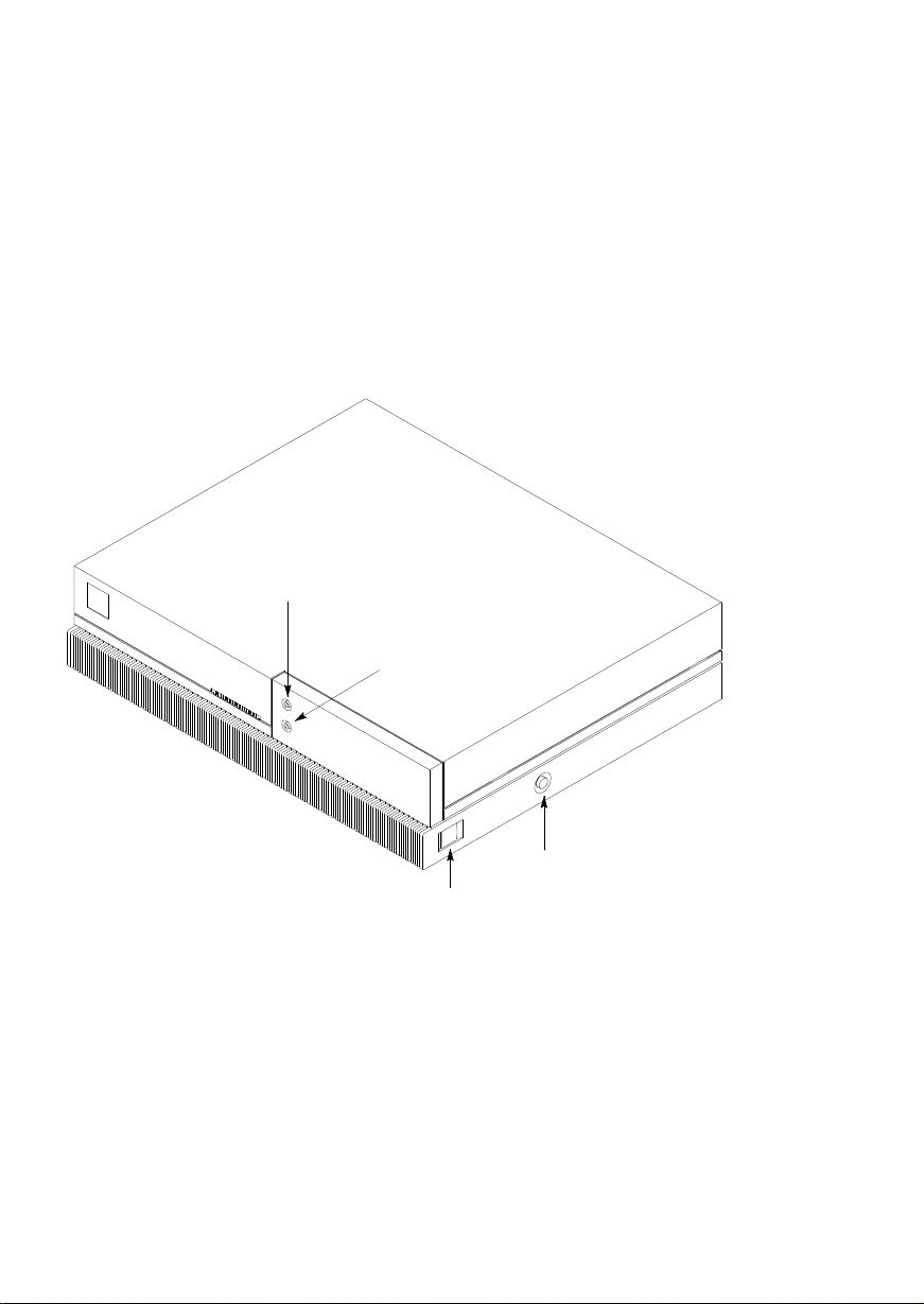
System Unit Controls and Front Panel Connectors
Figure 1–1 shows the Power and TOC (Transfer Of Control) switches.
Use the Power switch to power the system unit on and off.
Use the TOC switch to reset the operating system. Do not push the TOC switch un-
less you have first shutdown the operating system by using the shutdown command.
NOTICE: Model 715/64, 715/80, 715/100, and 715/100XC
workstations are equipped with a soft shutdown feature. These systems shut down the file system automatically when you power the system off.
Audio/Headphones OUT
Connector (Stereo)
Audio/Microphone IN
Connector (Stereo)
Front
Power Switch
TOC Switch
Figure 1–1. System Unit Controls
Figure 1–1 also shows the Audio connectors on the front panel. The workstation has
audio input and output capability through external input and output connectors and
an internal speaker. The line–in and line–out connectors are located on the rear panel
and are described later in this chapter. The front panel contains the Audio/Headphone
OUT and Audio/Microphone IN connectors.
The Audio/Headphone OUT connector is a stereo headphone output. The Audio/Mi-
crophone IN connector is a mono microphone input. The ring connector of the microphone jack supplies +1.5 volts dc for microphones that require it. A microphone for
1–4 Product Information
Page 18
audio input is not supplied with the workstation. The audio connectors are standard
stereo audio mini–jacks.
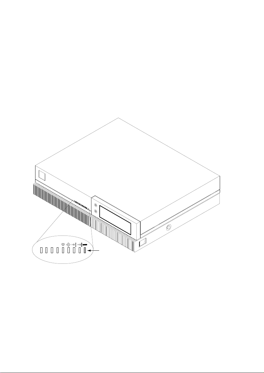
Understanding the LEDs
There are 9 Light Emitting Diodes (LEDs) located on the front of the system unit, as
shown in Figure 1–2. The green one on the far right is the Power LED. It lights when
the system unit power is on. The other eight are labeled 8 through 1 (left to right).
The rightmost four amber LEDs (labeled 4, 3, 2, and 1) show that the system is running the operating system and communicating over the network. Along with the leftmost four amber LEDs (8, 7, 6, and 5), they also help you to troubleshoot the workstation by coming on in certain patterns during system failures (see Chapter 4).
Front
Table 1–1 lists how the LEDs report during normal HP–UX system activity. The
green Power LED remains lit while the system is powered on.
Power
LED
Figure 1–2. Front Panel LEDs
Product Information 1–5
Page 19
Table 1–1. LED Display During Normal System Activity
LED Display
(1 Through 4 Flashing)
7658
= LED On or Flashing
Meaning
1234
Operating System Running
Disk Access In Progress
Network Receive In Progress
Network Transmit In Progress
1–6 Product Information
Page 20

System Unit Rear Panel Connectors
This section describes the following connectors on the system unit’s rear panel:
SCSI connector
HP parallel I/O connector
HP–HIL connector (Model 715/C, 715/33, 715/50, and 715/75 workstations)
10–pin modular jack (Model 715/64, 715/80, 715/100, and 715/100XC
workstations)
RS–232 serial input/output connectors
802.3 network connector
Built–in graphics connector
Optional connector for EISA, CRX, or HCRX graphics
Power cord connector
Audio connectors
NOTICE: To maintain FCC/EMI compliance, verify that all
Figure 1–3 shows the locations of the connectors on the system unit’s rear panel. The
symbols shown are depicted on the rear panel.
cables are fully seated and properly fastened.
Product Information 1–7
Page 21
Audio Line IN Connector
Power Cord Connector
LAN AUI Connector
RS–232 Connectors
HP–HIL Connector or 10–pin
Modular Jack
HP Parallel Connector
SCSI Connector
Power
Switch
Built–In Graphics
Transfer of Control
(TOC) Switch
Graphics Configuration Switches*
Connector
Optional Connector for EISA, CRX, or HCRX Graphics
Audio Line OUT Connector
*These switches are not present on Model 715/64, 715/80, 715/100, and 715/100XC
workstations. Model 715/64, 715/80, 715/100, and 715/100XC workstations are
autoconfiguring.
Figure 1–3. System Unit Rear Panel Connectors
1–8 Product Information
Page 22

SCSI Connector
Use the SCSI connector to connect external SCSI devices such as DDS–format tape
drives and CD–ROM drives. Consult the documentation that accompanies each SCSI
device for specific information concerning its use.
NOTICE: When attaching external SCSI devices, be sure to
terminate the last device on the external SCSI bus. If
no external devices are attached, the SCSI connector
does not need to be terminated.
HP Parallel I/O Connector
The 25–pin HP Parallel I/O interface port is provided for use with peripheral devices
using the Centronics interface protocols such as printers and plotters. Consult the
documentation that accompanies each peripheral device for specific information concerning its use.
HP–HIL Connector
Model 715/C, 715/33, 715/50, and 715/75 workstations are equipped with an
HP–HIL connector, which provides an interface for the system’s keyboard, mouse,
and other optional HIL input devices. Consult the documentation that accompanies
each input device for specific information concerning its use.
10–Pin Modular Jack
Model 715/64, 715/80, 715/100, and 715/100XC workstations are equipped with a
10-pin modular jack. A Keyboard Adapter Module attaches to this connector by
means of a special cable shipped with the unit. The Keyboard Adapter Module includes two mini–DIN connectors and an HP–HIL connector. The mini–DIN connectors provide an interface for a AT–style keyboard and other mini–DIN input devices.
The HP–HIL connector provides an interface for an HP keyboard, mouse, or other
optional HIL input devices. Consult the documentation that accompanies each input
device for specific information concerning its use.
RS–232 Serial Input/Output Connectors
You can attach a variety of peripheral devices to the two RS–232 Serial Input/Output
(SIO) ports on the workstation. These peripheral devices include printers, plotters,
modems, and scanners. Consult the documentation that accompanies each peripheral
device for specific information concerning its use.
Both SIO ports are programmable. You can set functions such as bit rate, character
length, parity, and stop bits. SIO Ports 1 and 2 are used as interfaces for serial
asynchronous devices to the CPU. Both ports operate at up to a 19.2 K baud rate.
Table 1–2 shows the SIO connector pin listings. The serial connectors are 9–pin
D–sub connectors. Signal names are those specified in the EIA RS–232 standard.
Product Information 1–9
Page 23

Table 1–2. Serial I/O Pins
Pin No. Signal
1
2
3
4
5
6 DSR
7
8
9RI
DCD
RXD
TXD
DTR
GND
RTS
CTS
Description
Data Carrier Detect
Receive Data
Transmit Data
Data Terminal Ready
Ground
Data Set Ready
Request To Send
Clear To Send
Ring Indicator
802.3 Network Connector
Figure 1–3 shows the location of the connector for the 802.3 (ETHERNET) network.
Connect an ETHERNET transceiver to this connector for communicating with a network.
Built–In Graphics Connector
If the workstation does not have the CRX, HCRX, or VISUALIZE graphics option
installed, use the built–in graphics connector to connect the monitor’s video cable to
the system. If the workstation is equipped with optional graphics, connect the monitor or external graphics unit to the optional graphics connect as described below. If
you are setting up a dual monitor system, connect one monitor to the built–in graphics connector and the other monitor to the optional graphics connector.
1–10 Product Information
Page 24
Connectors for EISA, and Optional Graphics
The system has a slot for an optional EISA (Extended Industry Standard Architecture) board or an optional CRX , HCRX , VISUALIZE or CRX–48 graphics board.
EISA
The one–slot EISA I/O port is a superset of ISA (Industry Standard Architecture). It
extends the capabilities of that standard while maintaining compatibility with ISA
expansion boards. EISA provides 32–bit memory addressing and 32–bit data transfers. The EISA slot allows quick and easy integration in heterogeneous networks as
well as simple connections of high–speed, low–cost disks and other peripherals.
Some EISA option boards have external connectors for connecting these devices.
Consult the documentation that accompanies each device for specific information
concerning its use.
Optional Graphics
If the system has an optional graphics board installed, it will have one of the following graphics connectors:
Color graphics card (CRX–24, CRX–24Z, HCRX–8, HCRX–8Z, HCRX–24,
HCRX–24Z , or VISUALIZE graphics) — This device has a D–sub miniature
connector which is connected to the monitor by a cable, as shown in Figure
Figure 1–4.
Graphics interface card (CRX–48Z graphics) — This device is connected by a
cable to an external graphics processor, which in turn is connected to a video
monitor, as shown in Figure Figure 1–5.
Figure 1–4 shows the location of the CRX or HCRX graphics connector on the system unit’s rear panel.
Product Information 1–11
Page 25
Figure 1–4. CRX and HCRX Graphics Connector
Figure 1–5 shows the locations of the CRX–48Z graphics connections on the system
unit’s rear panel and on the rear panel of the external graphics processor.
Graphics Processor Cable
to Graphics Processor
Tighten connections with
a flat–blade screwdriver.
Monitor Cable to
Graphics Processor
Figure 1–5. CRX–48Z Graphics Connections
Graphics Processor Cable
to Graphics Interface Board
Power Cable
to Graphics
Processor
Power Cord Connector
Plug the workstation’s power cord into the power cord connector to provide ac power
to the system.
Audio Line In and Audio Line Out Connectors
The Model 715 workstation has CD quality stereo audio input and output capability
through external input and output connectors on the front and rear panels and an internal speaker. A microphone for audio input is not supplied with the workstation.
The rear panel audio connectors are standard stereo audio mini–jacks and use audio
“line” levels.
1–12 Product Information
Page 26

Monitor Controls, Connectors, and Indicators
The Power–On LED, when lit, indicates that the monitor has ac power applied. Use
the following controls to adjust the monitor:
The Power–On/Off button turns the monitor’s power on and off.
The Brightness control adjusts the brightness of the display.
The Contrast control adjusts the light–to–dark and dark–to–light contrast of the
display.
The Degauss control demagnetizes the color monitor. Degaussing disperses any
accumulated magnetic charge from the face of the monitor. Magnetic disturbances such as picture distortion or color impurity can be caused by either
moving the monitor from one place to another or swiveling the monitor on its
base. No degauss control exists on the 19–inch grayscale monitor.
Refer to the manual that came with the monitor for detailed information about the
monitor’s controls, connectors, and indicators.
Product Information 1–13
Page 27

Keyboards
There are three types of Hewlett–Packard keyboards available for use with the
workstation. They are the following:
ITF Keyboard (Also known as Model # A1099C Keyboard)
PC Keyboard (Also known as the PC–101 (HIL) Keyboard, the “Enhanced
Vectra” Keyboard, and Model # A2205B Keyboard)
AT Keyboard (Industry–standard AT–style keyboard that uses
a mini–DIN, PS/2–style, connector, Model # A4030B)
CAUTION: When connecting a HIL device (such as the ITF key-
board) ensure that the device conforms to the
HP–HIL specification. Devices that are not HP–HIL
compatible but have similar connectors may appear
to be compatible, but will damage the system.
Keyboard Differences
Aside from the obvious difference in the appearance of the ITF and PC/AT keyboards
due to the arrangement of the keys, there is also a difference in the keys and their
output codes. Some keys on one keyboard (the ITF keyboard for example) may not
exist on the other keyboard. These keys generate codes which also may not exist as
output from the other keyboard (or may be generated by a different key). Codes that
are generated when a key is pressed are called keycodes.
Some applications expect to use keycodes generated by keys existing on one of the
keyboards (the ITF keyboard for example). Since the keys do not exist on the other
keyboard (the PC and AT keyboards), an accommodation must be made if the PC/AT
keyboard is to be used. In most cases, it is still possible to use some other key that is
equivalent (generates the same keycode from a different keycap). To do this, it is
necessary to know which keys are equivalent on the two keyboards. Table 1–3
compares the equivalent keys on the ITF and PC/AT keyboards.
NOTICE: Keyboard keys not mentioned in Table 1–3 are the
same on all the keyboards.
1–14 Product Information
Page 28

Table 1–3. PC/AT Keyboard to ITF Keyboard Equivalent Keys
PC/AT Keycap Symbol
F9 blank1 (left)
F10 blank2
F11 blank3
F12 blank4 (right)
PrintScreen / SysReq Menu
Scroll Lock Stop
Pause / Break Break / Reset
Page Up Prev
Num Lock System / User
End Select
Page Down Next
Enter Return
Alt (left) Extend Char (left)
Alt (right) Extend Char (right)
No Equivalent Clear Line
No Equivalent Clear Display
No Equivalent Insert Line
No Equivalent Delete Line
No Equivalent Print / Enter
No Equivalent , (number pad)
No Equivalent Tab (number pad)
ITF Keycap Symbol
(Continued)
Product Information 1–15
Page 29
Table 1–3. PC/AT Keyboard to ITF Keyboard Equivalent Keys (cont.)
PC/AT Keycap Symbol
Esc Esc / Del
Insert Insert Char
Home
Delete Delete Char
Caps Lock Caps
Esc Shifted Esc / Del Shifted
Pause / Break Shifted Break / Reset Shifted
Num Lock Shifted System / User Shifted
0 / Ins (number pad) 0 (number pad)
1 / End (number pad) 1 (number pad)
2 / B (number pad)
3 / Pg Dn
(number pad)
4 / A (number pad)
6 / " (number pad
7 / Home
(number pad)
8 / Y (number pad)
9 / Pg Up
(number pad)
. / Del (number pad) . (number pad)
Ctrl (left) Ctrl
Ctrl (right) No Equivalent
ITF Keycap Symbol
2 (number pad)
3 (number pad)
4 (number pad)
6 (number pad)
7 (number pad)
8 (number pad)
9 (number pad)
1–16 Product Information
Page 30

Environmental/
Installation/PM 2
This chapter lists the environmental specifications and regulatory requirements for
the system. Installation and preventive maintenance information, if applicable, is also
provided.
Environmental Specifications
Table 2–1 lists the environmental specifications.
Table 2–1. Environmental Specifications for Models 715
Type Specification
Operating
Temperature +5 to +40° C
Non–Operating
Temperature -40 to +70° C
Humidity 15–80% maximum operating @ 40° C
Operating
Altitude 3100 meters
Acoustic Noise Sound Power Level (LWA) < 4.4 Bells
to 30° C (diskless)
Electrical Input 100 to 120 Vac
220 to 240 Vac
60 Hz range, 57 to 63 Hz
50 Hz range, 47 to 53 Hz
Minimum voltage 88 Vac
Maximum voltage 269 Vac
3.8 amps @ nominal 110 Vac
1.8 amps @ nominal 220 Vac
Maximum
Heat Dissipation 205 W or 700 BTUs
Environmental/Installation/PM 2–1
Page 31

Regulatory Requirements
The following regulatory requirements are met:
FCC Class A
VCCI Class 1
EN55022 Class A
UL1950
GS Mark
– IEC 950/EN60950
– ZH1/618
CSA C22.2–950M
Installation
Refer to the following manuals for system installation information:
HP 9000 Series 700 Model 715 Hardware Installation Guide (Part Number
A2084–90628)
HP 9000 Series 700 Model 715 Owner’s Guide (Part Number A2084–90629)
Preventive Maintenance
There is no preventive maintenance for the system unit. Removable media storage
devices may require operator preventive maintenance. Refer to the HP 9000 Series
700 Model 715 Owner’s Guide (Part Number A2084–90629) for more information.
2–2 Environmental/Installation/PM
Page 32

Configuration 3
This chapter provides details on setting up and changing the system configuration.
Workstation and System Unit Configurations
Refer to the HP 9000 Series 700 Configuration Guide for a complete list of supported accessories, peripherals, and operating systems.
FRU Configurations
This section provides information for setting up or changing the configuration of the
system Field Replaceable Units (FRUs).
Mass Storage Configurations
Figures 3–1 through 3–11 show the SCSI ID settings for mass storage devices.
NOTICE: The SCSI terminators must be removed from all in-
ternal SCSI devices. An external terminator is not
required if there are no external devices attached.
Configuration 3–1
Page 33

Internal System Drives:
System SCSI Drive(s)
1st Winchester Drive (if present, uses SCSI ID 6)
2nd Winchester Drive (if present, uses SCSI ID 5)
Floppy Disk Drive* (if present, uses SCSI ID 0)
CD–ROM Drive (if present, uses SCSI ID 2)
4–mm DDS Tape Drive (if present, uses SCSI ID 3)
External Device Drives:
External SCSI HP 6000 Series 660A Disk Subsystem,
Product No. C2213A (These are not default IDs as shipped –
you must set the IDs to the correct setting.)
1st Winchester Drive (ID No. 4)
2nd Winchester Drive (ID No. 3)
3rd Winchester Drive (ID No. 0)
4–mm DDS Tape Drive (ID No. 3)
Magneto–Optical Drive (ID No. 0)
600–MB CD–ROM (ID No. 2)
External SCSI HP Standalone
Magneto–Optical Drive (C1701A) (ID No. 0)
CD–ROM Drive (A1999A) (ID No. 2)
20–GB Magneto–Optical Autochanger (C1700A)
st
1
(ID No. 3)
2nd (ID No. 4)
3rd (ID No. 5)
*Model 715/64, 715/80, 715/100, and 715/100XC workstations have a PC–
style floppy and do not use a SCSI address for the floppy drive.
Figure 3–1. Default SCSI IDs
NOTICE: These SCSI IDs are the recommended IDs for each
storage device. If an existing device already uses an
ID, select an alternate ID.
3–2 Configuration
Page 34

LED
NOTICE: A0, A1, and A2 are the SCSI
ID jumpers. The jumpers TE,
SS, WS, and I/O should be
removed
and INT should be
, and the jumper EP
in place
.
SCSI
ID
6
SCSI
ID
5
I/O
INT
SS
TE
EP
WS
A0 (LSB)
A1
A2 (MSB)
Figure 3–2. Quantum 525–MB and 1–GB Disk Drive Jumpers
(1 GB only)
Configuration 3–3
Page 35

SCSI
1 2 3 4 5 6 7 8 9 10
ID
6
5
4
3
2
1
0
No Jumper
Figure 3–3. Quantum 1–GB and 2–GB Low Profile Disk Drive Jumpers
3–4 Configuration
Page 36

LED
Front View
1 — Write Protect
2 — Unit Attention
3 — SDTR
4 — Parity Enable
5 — Auto Spin–Up
6 — Sync Spindle
7 — Sync Spindle
(First Drive)
(Second Drive)
1 2 3 4 5
Bottom View
6 71 2 3 4 5
6 7
Front
SCSI ID 6
8 9 10
SCSI ID 5
8 9 10
NOTICE: The last three jumpers
(8, 9, and 10) are the
SCSI ID jumpers.
Jumpers 1, 2, and 7
should be
removed
, and
jumpers 3, 4, 5, and 6
should be
in place
.
Terminator
Power
Figure 3–4. Hewlett–Packard 1–GB Winchester Drive Jumpers
Configuration 3–5
Page 37

Terminator Power
Terminator Resistor
Modules
(Must be removed)
(First Drive)
2345
(Second Drive)
2345
61
61
Parity Enable Configuration
NOTICE: The first three jumpers
(1, 2, and 3) should be
removed
SCSI
ID 6
SCSI
ID 5
jumpers are jumpers
4, 5, and 6.
. The SCSI ID
Figure 3–5. Seagate 525–MB, 1–GB, and 2–GB Winchester Drive Jumpers
3–6 Configuration
Page 38

Terminator Resistor Modules
(Must be removed)
Factory–Installed Jumpers
(Do not remove)
(First Drive) (Second Drive)
SCSI
ID 6
ID 0
ID 1
ID 2
P ARITY
WPROT
SPIN 0
SPIN 1
SCSI
ID 5
ID 0
ID 1
ID 2
P ARITY
WPROT
SPIN 0
SPIN 1
NOTICE:
ID 0, ID 1, and ID 2 are the SCSI ID jumpers. The jumpers PARITY,
WPROT, SPIN 0, and SPIN 1 should be
Figure 3–6. Micropolis 1–GB Winchester Drive Jumpers
removed
.
Configuration 3–7
Page 39

LED
NOTICE: A0, A1, and A2 are the
SCSI Terminators
(Must be removed)
Figure 3–7. Quantum 210–MB and 425–MB Winchester Drive Jumpers
(Models ProDrive 210S and ProDrive 425S)
SCSI ID jumpers.
SCSI
ID 5
SCSI
ID 6
Sync Spindle
Parity Enable
Write Protect
A2
A1
A0
3–8 Configuration
Page 40

LED
Front View
J3
SCSI ID
J3
5
1 2345678910
Termination Header
Bottom View
J3
Figure 3–8. DEC 1–GB and 2–GB Disk Drive Jumpers
NOTICE: The first three jumpers (1, 2,
and 3) are the SCSI ID
jumpers. Only jumpers 1, 3,
and 7 should be
other jumpers should be
removed
.
Back
NOTICE:
Remove
all jumpers.
in place.
All
Configuration 3–9
Page 41

10
9
8
New Board
SCSI
ID 5
SCSI
ID 6
A0
A1
A2
Front of Drive
7
6
5
4
3
2
1
Synch Spindle
Synch Spindle
Auto Spin Up
Parity
SDTR
Unit Attention
Write Protec
t
Old Board
SCSI
ID 5
9
8
7
6
5
4
3
2
1
SCSI
ID 6
A0
A1
A2
Synch Spindle
Synch Spindle
Auto Spin Up
Parity
SDTR
Unit
Attention
SCSI Terminators
(Old Board)
SCSI Terminator
Jumpers
(New Board)
Figure 3–9. Hewlett–Packard 420–MB Winchester Drive Jumpers (Model C2235)
3–10 Configuration
Page 42

SCSI
ID
6
5
4
3
2
1
0
1 GB is Model HPC3324A
2 GB is Model HPC3325A
Figure 3–10. Hewlett–Packard 1–GB and 2–GB Low Profile Drive Jumpers
Configuration 3–11
Page 43

Top of Floppy Disk Drive
SCSI ID Address Jumpers
ID 2
ID 1
ID 0
Jumper in = 0; out = 1
Terminator
Resistor
Modules
(Must be removed)
ID2
Jumpers
ID1
ID0
Figure 3–11. SCSI Floppy Drive Address Jumper Settings
3–12 Configuration
Target ID
012345
(Default)
6
Page 44

Model
XM–3201B
SCSI
Address
Switches
Target
ID
0
1
(Default)
2
3
SCSI Terminators
(must be removed)
T arget
ID
0
Address
Settings
Jumpers
Target ID
4
5
6
Model
XM–3301B
T arget
ID
4
Address
Settings
Jumpers
1
2
(Default)
5
6
3
Figure 3–12. CD–ROM SCSI Address Jumper Settings
Configuration 3–13
Page 45

SCSI Terminators
(must be removed)
Target
ID
0
1
2
T erm
PWR
Jumpers
ID2 ID1 ID0 ID2 ID1 ID0
Target
ID
T erm
PWR
4
5
6
3
(Default)
Figure 3–13. DDS SCSI Address Jumper Settings (Model C1504C)
Jumpers
3–14 Configuration
Page 46

Installing Additional Memory
Figure 3–14 shows the location of the memory boards within the system unit.
Memory Boards
Figure 3–14. Memory SIMM Locations
Configuration 3–15
Page 47

%')0 ')* %,*+ #&*+$$ #& (#)* ' +" *% %%')0 (#+0 ',
%0 #&*+$$ ,( +' +") (#)* ') +" '$ & ,( +' ',) (#)* '
%%')0 ')* ') $$ '+") %'$*
&
" %%')0 '&&+')* ) $$ #) +")',!" #) ') +" '$
& #) +")',!" #) ') $$ +" '+") %'$* &*+$$ %%')0 ')* #& +"
$'.*+&,%) %(+0 '&&+') (#) #)*+ ') /%($ # 0', "- +.' (#)*
' %%')0 ')* #&*+$$ +" #)*+ (#) #& +" '&&+')* $$ & +"
*'& (#) #& +" '&&+')* $$
%'-$)($%&+ ()',)* ') * ) ()'-# #& "(+)
Right
Side of
System
Unit
Figure 3–15. Memory Connector Configuration
3–16 Configuration
A B
A B A B A B
Front of System Unit
Pair 0Pair 1Pair 2Pair 3
Page 48

Changing the Built–In Graphics Configuration
Switches (Models 715/C, 715/33, 715/50, 715/75)
Figure 3–16 shows the built–in graphics configuration switch settings. Set the
switches according to the type of monitor that is connected to the system unit’s built–
in graphics connector. First open the system unit, as described in Chapter 5, to allow
a clear view of the switches. Use a small probe to set the switches through the access
hole on the rear of the system unit.
NOTICE: The built–in graphics configuration switches have no
affect on the operation of the optional CRX graphics
unit (if installed).
Access Hole
20” Color
17” Color
19” Grayscale
15” Color
(Model 715/33 only)
Figure 3–16. Changing the Graphics Configuration Switches
Configuration 3–17
Page 49

Configuring the CRX Graphics Options
This section describes how to configure the system to use the CRX graphics options
(if installed).
For information about HCRX graphics, refer to the HP A4070A/A4071A/A4072A CE
Handbook (A4070–90099).
If you update or reinstall HP–UX, and after a few minutes, there is no output on the
monitor, use the following procedures to configure the workstation:
1. Power off the workstation.
2. Connect the monitor to the built–in graphics connector as shown in Chapter 1
of this manual.
3. For Model 715/C, 715/33, 715/50, and 715/75 workstations, check the
workstation’s graphics configuration switches, as shown earlier in this chapter, to make sure the graphics switches are set correctly for the monitor.
4. Power on the monitor and the workstation.
5. Immediately after you power on the workstation, press the TOC switch on
the right side of the system unit. (See Chapter 1 of this manual for the TOC
switch location.)
6. If you are setting up a single monitor system, follow the steps in the next
subsection. If you are setting up a dual monitor system, go to the subsection
“Setting Up a Dual Monitor System” for further configuration instructions.
Setting Up a Single Monitor System
This subsection describes how to set up the workstation to use only the CRX graphics.
NOTICES: Only the 20–inch color monitors are supported on the
CRX graphics adapters.
The built–in graphics adapter can use any of the supported monitors.
1. Log in as root.
2. Enter the following command line to create a device file to support the CRX
graphics:
/etc/mknod /dev/crt24 c 12 0x100000
3–18 Configuration
Return
Page 50

3. Enter the following command line to set the attributes of the device file:
chmod 666 /dev/crt24
Return
4. Make a backup copy of /usr/lib/X11/X0screens by entering the following
command line:
cp /usr/lib/X11/X0screens /usr/lib/X11/X0screens.backup
Return
5. Use a text editor, such as vuepad or vi, to edit the following file:
/usr/lib/X11/X0screens
6. Edit the file so that every line begins with a pound sign (#).
7. Add the following line to the file exactly as shown:
/dev/crt24
8. Save the changes and close the file.
9. Enter the following command:
/etc/reboot
10. The system shuts down and starts to reboot. Press and hold
Return
Esc
when
the following message is displayed:
Selecting a system to boot. To stop selection
process press and hold the ESCAPE key.
In a few seconds, the following message appears:
Terminating selection process.
A short time later, the following message appears:
Searching for potential boot devices. To
terminate search, press and hold the ESCAPE key.
Configuration 3–19
Page 51

The workstation is now searching for devices that may hold file systems from
which it can boot HP–UX. As they are found, they appear in a list similar to
the following example:
Device Selection Device Path
Device Type
––––––––––––––––––––––––––––––––––––––––––––––––––––––––––
QUANTUM LPS525s
QUANTUM LPS525s
TOSHIBA CD–ROM DRIVE:XM
P0 scsi.6.0
P1 scsi.5.0
P2 scsi.2.0
11. The following list of actions appears:
b) Boot from specified device
s) Search for bootable devices
a) Enter boot administration mode
x) Exit and continue boot sequence
?) Help
Select from menu:
Press a
Return
The following prompt appears:
BOOT_ADMIN>
12. Set the default console to the CRX graphics option by entering the following
command line:
BOOT_ADMIN> path console graphics_2
Return
13. Enter the following command:
BOOT_ADMIN> exit
Return
14. Power off the workstation and the monitor.
15. Connect the color monitor to the CRX graphics connector as shown in Chapter 1 of this manual.
16. Power on the monitor and the workstation.
3–20 Configuration
Page 52

Setting Up a Dual Monitor System
This subsection describes how to set up the workstation to use both the optional
graphics (CRX) and the built–in graphics.
The CRX graphics is set up as the default display and console device and the built–in
graphics is set up as the secondary display device.
NOTICES: Dual monitors are supported only with the CRX–24
graphics options.
Only the 20–inch color monitors are supported on the
CRX graphics adapters.
The built–in graphics adapter can use any of the supported monitors.
1. Log in as root.
2. Enter the following command line to create a device file to support the CRX
graphics adapter:
/etc/mknod /dev/crt24 c 12 0x100000
Return
3. Enter the following command line to set the attributes of the device file:
chmod 666 /dev/crt24
Return
4. Make a backup copy of /usr/lib/X11/X0screens by entering the following
command line:
cp /usr/lib/X11/X0screens /usr/lib/X11/X0screens.backup
Return
5. Use a text editor, such as vuepad or vi, to edit the following file:
/usr/lib/X11/X0screens
6. Edit the file so that every line begins with a pound sign (#).
Configuration 3–21
Page 53

7. Add the following two lines to the file exactly as shown and in the order
shown:
/dev/crt24
/dev/crt
Since the device file for the CRX graphics is listed first, it becomes the default (0.0) display device and the built–in graphics becomes the secondary
(0.1) display device.
8. Save the changes and close the file.
9. Use a text editor, such as vuepad or vi, to edit the following file:
/usr/vue/app–defaults/Vuewm
10. Add the following two lines exactly as shown:
Vuewm*multiScreen: True
Vuewm*screenList: One Two
11. Save the changes and close the file.
12. Enter the following command:
/etc/reboot
Return
13. The system shuts down and starts to reboot. Press and hold
the following message is displayed:
Selecting a system to boot. To stop selection
process press and hold the ESCAPE key.
In a few seconds, the following message appears:
Selection process stopped.
A short time later, the following message appears:
Searching for potential boot devices. To terminate
search, press and hold the ESCAPE key.
Esc
when
3–22 Configuration
Page 54

The workstation is now searching for devices that may hold file systems from
which it can boot HP–UX. As they are found, they appear in a list similar to
the following example:
Device Selection Device Path
Device Type
––––––––––––––––––––––––––––––––––––––––––––––––––––––––––
QUANTUM LPS525s
QUANTUM LPS525s
TOSHIBA CD–ROM DRIVE:XM
P0 scsi.6.0
P1 scsi.5.0
P2 scsi.2.0
14. The following list of actions appears:
b) Boot from specified device
s) Search for bootable devices
a) Enter boot administration mode
x) Exit and continue boot sequence
?) Help
Select from menu:
Press a
Return
The following prompt appears:
BOOT_ADMIN>
15. Set the default console to the CRX graphics option by entering the following
command line:
BOOT_ADMIN> path console graphics_2
Return
16. Enter the following command:
BOOT_ADMIN> exit
Return
17. Power off the workstation and the monitor.
18. Connect the color monitor to the CRX graphics connector as shown in Chapter 1 of this manual. Connect the second monitor to the built–in graphics
connector on the rear of the workstation, as shown in Chapter 1. For Model
715/C, 715/33, 715/50, and 715/75 workstations, check the workstation’s
graphics configuration switches, as shown in earlier in this chapter, to make
sure the graphics switches are set correctly for the second monitor.
19. Power on the monitors and the workstation.
Configuration 3–23
Page 55

Troubleshooting 4
This chapter provides information about isolating a failing Field Replaceable Unit
(FRU).
To troubleshoot HP workstations, you must be familiar with the HP–UX operating
system. You must be able to start and stop processes. You should also be familiar
with the Boot ROM Test Mode, ISL diagnostics, and the SupportWave online tests.
For Series 700 systems, note any error or status messages, and then run the power–up
boot ROM diagnostics, known as Self Test. If the Self Test diagnostics fail, replace
the FRU that is indicated. If the tests pass but you still suspect a problem, run the ISL
diagnostics and the SupportWave online tests. Refer to the following sections for
more information about Self Test.
For a complete description on using ISL diagnostics and SupportWave, see the
Precision Architecture RISC HP 9000 Series 700 Diagnostics Manual.
Troubleshooting 4–1
Page 56

LED Error Codes
This section contains information about the error codes displayed by the LEDs on the
system’s front panel.
If an error occurs during the power–up diagnostics tests, the diagnostics use the front
panel LEDs to display a code for the failing component.
Figure 4–1 shows the location of the system unit’s front panel LEDs. There are nine
LEDs on the front panel. The green LED on the far right indicates that the system is
powered up. The amber LEDs labeled 1 through 8, right to left, indicate system
status and error codes.
Front
8765432
Table 4–1 through Table 4–4 show the LED error codes as they appear on the front
panel display of Model 715/C, 715/33, 715/50, and 715/75 workstations.
Table 4–1 shows the Self Test error codes.
Table 4–2 shows the PDC error codes.
Table 4–3 shows the ISL error codes.
Table 4–4 shows the HP–UX kernel error codes.
Table 4–5 shows the LED error codes as they appear on the front panel display of
Model 715/64, 715/80, , 715/100, and 715/100XC workstations.
Use these LED codes to determine the failing component.
4–2 Troubleshooting
1
Power
LED
Figure 4–1. Front Panel LEDs
Page 57

Table 4–1. Model 715/C, 715/33, 715/50, and 715/75 Self Test LED Error Codes
LED Display Error Message
7658
1234
CPU Error - Model 715/33 and 50.
PCX-T FRU Error – Model 715/75.
CPU Error - Model 715/33 and 50.
PCX-T FRU Error - Model 715/75.
CPU Error - Model 715/33 and 50
Motherboard Error - 715/75
CPU Error - Model 715/33 and 50.
PCX-T FRU Error - Model 715/75.
FP Register Test Failure. Loops Until Passes
Possible PCX–T Error*
FP Register Test Failure. Loops Until Passes
Possible PCX–T Error*
FP Register Test Failure. Loops Until Passes
Possible PCX–T Error*
EISA Interface Error.
EISA Interface Error.
EISA Interface Error.
EISA Interface Error.
EISA Interface Error.
EISA Interface Error.
PDC ROM Checksum Error.
Memory Pair 0, Slot B Error.
Memory Pair 0, Slot A Error.
= LED On or Flashing
* If you see this error code and it continues to appear, power the system down
and reboot. If you see the error code again, replace the PCX–T card.
= LED Either On or Off
(Continued)
Troubleshooting 4–3
Page 58

Table 4–1. Model 715/C, 715/33, 715/50, and 715/75 Self Test LED Error Codes
LED Display Error Message
(Cont.)
7658
1234
Memory Pair1, Slot B Error.
Memory Pair 1, Slot A Error.
Memory Pair 2, Slot B Error.
Memory Pair 2, Slot A Error.
Memory Pair 3, Slot B Error.
Memory Pair 3, Slot A Error.
No Memory found.
Unknown I/O device.
Error while trying to boot from SCSI Device.
Error while trying to boot from LAN.
Error Trying to access Console Keyboard.
Error while trying to access Serial
Console Device, Port A.
Error while trying to access Serial
Console Device, Port B.
Error while trying to access Parallel Port.
Error while trying to access Graphical
Console Device.
= LED On or Flashing
4–4 Troubleshooting
(Continued)
Page 59

Table 4–1. Model 715/C, 715/33, 715/50, and 715/75 Self Test LED Error Codes
LED Display Error Message
(Cont.)
7658
= LED On or Flashing
1234
Unable to initialize EISA Slot.
Error on SGC Slot 1 (Built–in Graphics)
Error on SGC Slot 2 (Optional Graphics)
Troubleshooting 4–5
Page 60

Table 4–2. Model 715/C, 715/33, 715/50, and 715/75 PDC LED Codes
LED Display
87 432156
Status
Destructive Memory init.
Non–Destructive Memory init.
Console selection.
Boot Device selection.
Autoselection failure to find Boot Device.
Launching IPL.
TOC Handler entered.
Branching to OS TOC Handler.
Branching to OS HPMC Handler.
EISA Subsystem Init.
Setting Up Default EISA config.
At least one Selftest failed (Service Mode).
= LED On or Flashing
4–6 Troubleshooting
Error reading EEPROM or
Invalid Stable Storage.
Unexpected interrupt.
No Console located.
(Continued)
Page 61

Table 4–2. Model 715/C, 715/33, 715/50, and 715/75 PDC LED Codes (Cont.)
LED Display
87 432156
= LED On or Flashing
Status
HPMC Handling initiated.
HPMC due to Cache Error.
HPMC due to Memory Error.
HPMC due to Bus Error.
Nested HPMC detected.
Error writing to EEPROM.
Unable to determine valid Processor Speed.
ROM Checksum error.
Processor Speed sensing.
Illegal Processor Speed/Clock Ratio sensing.
Bad Memory Hardware.
Troubleshooting 4–7
Page 62

Table 4–3. Model 715/C, 715/33, 715/50, and 715/75 ISL LED Codes
LED Display
87 432156
Status
ISL executing.
ISL is autobooting from the Autoexec File.
ISL cannot find Autoexecute File.
No Console found. ISL Autobooting.
Directory of Utilities is too large.
Autoexec File is inconsistent.
Error reading Autoexec File.
Error reading from Console.
Error writing to Console.
Not an ISL command or utility.
Utility File Header inconsistent:
Invalid System ID.
Error reading Utility File Header.
= LED On or Flashing
4–8 Troubleshooting
Utility File Header inconsistent:
Bad Magic Number.
Utility would overlay ISL in Memory.
Utility requires more Memory than is
configured.
Error reading Utility into Memory.
Incorrect Checksum: Reading Utility into
Memory.
(Continued)
Page 63

Table 4–3. Model 715/C, 715/33, 715/50, and 715/75 ISL LED Codes (Cont.)
LED Display
87 432156
= LED On or Flashing
Status
System Console needed.
Internal inconsistency: Invalid Boot Device
Class.
Destination Memory Address of Utility is
invalid.
Internal inconsistency: pdc_cache entry.
Internal inconsistency: IODC ENTRY_INIT.
Internal inconsistency: IODC
ENTRY_INIT Console.
Internal inconsistency: IODC
ENTRY_INIT Boot Device.
Utility File Header inconsistent: Bad aux_id.
Bad Utility File Type.
Troubleshooting 4–9
Page 64

Table 4–4. Model 715/C, 715/33, 715/50, and 715/75 HP–UX Kernel LED Codes
LED Display
87 432156
= LED On or Flashing
Status
Kernel loaded and Initialization begun.
Kernel has entered main().
Kernel is about to configure I/O System.
Kernel is about to mount Root File System.
Kernel is about to set up Page–Out Daemon.
Kernel is about to start the “INIT” Process.
Shutdown in process.
TOC Dump.
HPMC Dump.
Operating System executing with Load
Indicator X.
4–10 Troubleshooting
Page 65

Table 4–5. Model 715/64, 715/80, , 715/100, and 715/100XC LED Error Codes
LED Display Status
87 432156
CPU Error
Fatal Error
RAM Test Error
Cache Error
FP Co–processor Error
Fatal FP Co–processor Error
I/O Device Error
ROM Checksum Error
HPMC Error
HPMC due to Cache Error
= LED On or Flashing
HPMC due to Bus Error
HPMC due to Memory Error
Console Initialization Error
No working console found, unable to boot
(Continued)
Troubleshooting 4–11
Page 66

Table 4–5. Model 715/64, 715/80, , 715/100, and 715/100XC LED Error Codes
LED Display Status
87 432156
= LED On or Flashing
(Cont.)
No bootable device found
Memory Error
Initialization Error
4–12 Troubleshooting
Page 67

Dealing with a Boot Failure
If the workstation’s usual boot device (typically a disk) is not responding as it should,
you must attempt to boot from the disk (or another boot device) by selecting it manually.
To boot a device manually, follow these steps:
1. Turn off the power to the workstation, wait a few seconds, then turn the power
back on.
2. Press and hold
Selecting a system to boot.
To stop selection process, press and hold the ESCAPE
key.
Release
Selection process stopped.
Esc
as soon as the following message appears:
Esc
as soon as this message appears:
A short time later, this message appears:
Searching for potential boot devices.
To terminate search, press and hold the ESCAPE key.
The workstation is now searching for devices that may hold file systems from
which it can boot HP–UX. As they are found, they appear in a list, similar to
the following sample list:
Device Selection Device Path Device Type
––––––––––––––––––––––––––––––––––––––––––––––––––––––
P0 scsi.6.0 QUANTUM LPS525S
P1 scsi.5.0 QUANTUM LPS525S
P2 scsi.2.0 TOSHIBA CD–ROM DRIVE
This process may take several minutes. You can terminate the search at any
time by pressing
Esc
.
Troubleshooting 4–13
Page 68

When the search ends, the following list of actions appears:
b) Boot from specified device
s) Search for bootable devices
a) Enter Boot Administration mode
x) Exit and continue boot sequence
?) Help
Select from menu:
If no disk devices are listed, then the workstation is failing to communicate
with its disks. Recheck the SCSI connections and try again.
If no devices are listed at all, try alternative methods for booting, such as connecting an external CD–ROM drive.
3. If the search locates a disk, attempt to boot from it by entering the b (boot)
command and a device selection number from the list. For example, if a SCSI
disk is listed as item P0 (as in the example list above), enter the following:
Select from menu: b p0
Return
After a few seconds, the boot messages begin to appear on the screen. You may
hear sounds coming from the disk drive and see a sequence of changing patterns on the LED display.
4. If the workstation still fails to boot, there is either something wrong with the
file system or with the hardware.
Boot Administration Environment
The Boot Console User Interface provides an “autoselect” or “interactive” environment after the power–on sequence. The Boot Console User Interface must be invoked before the Initial Program Loader (IPL) routine. Users do not have to interact
with the interface when the AUTOSELECT mode is enabled.
The Boot Console User Interface executes user–entered commands that perform the
following functions:
Display the state of Autoselect mode using the AUTO command.
Set the state of the Autoselect mode using the AUTOSELECT command with
either the ON or OFF option.
Boot from the primary or alternate boot path or any specified path using the
BOOT command.
Set or display the real–time clock value using the DATE command (this com-
mand is not supported on Model 715/64, 715/80, , 715/100, and 715/100XC
workstations).
Return to previous menu using the EXIT command.
4–14 Troubleshooting
Page 69

Set or display the Fastsize value (amount of memory initialized during boot)
using the FASTSIZE command.
Display a menu of commands using the HELP command or a description of
any command as an option to the HELP command.
Display the model number, version numbers, and jumper settings on the Sys-
tem card using the INFO command.
Display the current STATION ADDRESS value in stable storage using the
LAN_ADDR command. You must use SS_CONFIG to set this value.
Select an operating system for the next boot attempt using the OS command.
Set or display the current values for the console, keyboard, primary, or alter-
nate boot paths using the PATH command.
Display the most recent HPMC, LPMC, or TOC error information logged into
Stable Storage using the PIM_INFO command.
Reset the System Unit using the RESET command.
Search for possible boot devices using the SEARCH command.
Set or display secure boot mode or the ability to interact with the console de-
vice within the first 10 seconds before boot device selection is disabled using
the SECURE command.
Display the results of the previous search command using the SHOW com-
mand (this command is not supported on Model 715/64, 715/80, , 715/100, and
715/100XC workstations).
Syntax checking is performed for any supported commands. Error status is displayed
on the console along with any relevant information.
Stable Storage
Stable Storage is non–volatile memory associated with each PA–RISC processor
module. Stable storage is used by the processor (CPU) to store device path information, the state of the boot flags, HPMC error information, and operating system initialization data.
Troubleshooting 4–15
Page 70

Boot Command Notations
The BOOT command supports the following three notations:
Mnemonic
PA–RISC I/O
Path number
Type help scsi or help lan for more information on the boot path parameters.
Here are examples of mnemonic notation:
BOOT
Return
with “no parameters” selects the primary boot path in stable
storage.
BOOT with the ALTERNATE or ALT parameter selects the alternate boot
path in stable storage.
Here are examples of PA–RISC I/O notation:
BOOT scsi.<scsi_addr>.<scsi_lun> or
BOOT 2/0/1.<scsi_addr>.<scsi_lun>
BOOT lan.<server_address>.<init_timeout>.<io_timeout>or
BOOT 2/0/2.<server_address>.<init_timeout>.<io_timeout>
Here is an example of path number notation:
BOOT P1
Return
attempts to boot from the second path indicated by the
SEARCH command.
Supported Boot Paths
SCSI devices are bootable when connected to the SCSI port on the System card.
Diskless workstations can only boot from the LAN port on the System card.
4–16 Troubleshooting
Page 71

ISL Environment
The ISL environment provides the means to load the operating system (HP–UX)
environment. The ISL environment also provides an offline platform to execute diagnostic and utility programs from a boot device when HP–UX does not load.
The ISL program is the first program loaded into main memory from an external
media (LAN, disk, or tape) and launched by the initial program loader (IPL) routine
during the Boot Administration environment.
The ISL environment provides the following capabilities:
Execute user–entered commands to modify boot device paths and boot options
in stable storage.
Run off–line diagnostic programs (TDIAG, EISADIAG, and IOMAP).
Provide automatic booting of the HP–UX O/S after power–on or reset.
The ISL program provides a standalone environment for loading offline diagnostic
and utility programs from the LIF directory. The ISL program also provides user
commands to configure the boot parameters into Stable Storage.
Invoking the ISL Environment from a SCSI Device
Perform the following steps to invoke the ISL environment from a SCSI device:
1. Power–on the System Unit (or cycle the power) to invoke the Boot
Administration mode (environment). The following screen appears:
b) Boot from specified device
s) Search for bootable devices
a) Enter Boot Administration mode
x) Exit and continue boot sequence
?) Help
Select from menu:
Troubleshooting 4–17
Page 72

2. Type s
Return
to search for devices with the ISL program and hpux
(loader) utility in their LIF directory. The following screen appears:
Searching for devices. Bootable Media.
To terminate search, press and hold the ESCAPE key.
Device Selection Device Path Device Type
––––––––––––––––––––––––––––––––––––––––––––––––––
P0 scsi.6.0 QUANTUM LPS525S
b) Boot from specified device
s) Search for bootable devices
a) Enter Boot Administration mode
x) Exit and continue boot sequence
?) Help
Select from menu:
IPL
3. Type b p0 ipl
Return
to invoke the ISL environment from the 525 MB
Quantum disk. The following messages, the ISL banner, and the ISL prompt
are displayed:
Trying scsi.6.0
Boot path initialized.
Attempting to load IPL.
Hard booted.
ISL Revision A.00.24 Oct. 7, 1992
ISL>
4. Type ls
Return
or listf
Return
to review the state of the ISL boot
flags, the ISL commands, and the files in the LIF directory on the scsi device.
5. Type hpux boot disc(;0)/hp–ux
Return
to load the HP–UX environment
from the SCSI device.
4–18 Troubleshooting
Page 73

ISL User Commands
There are several commands available in the ISL environment that allow a user to
obtain information about the boot characteristics of the system or to modify these
characteristics.
display – displays the boot and console paths in Stable Storage and the current
setting of the ISL Boot Flags.
primpath – modifies the primary boot path entry in Stable Storage. The entry
in Stable Storage for the primary boot device begins at byte address 0 and ends
at byte address 31.
altpath – modifies the alternate boot path entry in Stable Storage. The entry for
the alternate boot device begins at byte address 128 and ends at 159.
conspath – modifies the console path entry in Stable Storage. The entry in
Stable Storage for the console device begins at byte address 96 and ends at byte
address 127. The entry for the keyboard and mouse devices begins at byte address 160 and ends at 191.
listautofl or lsautofl – lists the contents of the (HP–UX) autoboot file.
support – boots the Support Tape from the boot device.
readss – displays 4 bytes (one word) from Stable Storage. The readss com-
mand requires a decimal number between 0 and 255 to address four bytes in
Stable Storage.
Running the ISL-Based Diagnostics
To run the external media (LAN, disk, or tape)-based ISL diagnostics:
1. Invoke the ISL environment from the external media (LAN, disk, or tape).
2. Type tdiag
the external media. (This test takes several minutes to complete and appears to
be in a loop when a graphics monitor is the system console.
NOTICE: tdiag contains a loopback test for audio testing. To
Return
after the ISL> prompt to invoke the TDIAG test from
run the loopback test, you need to attach the audio
test cable (part number 46081-61601) to the audio
input and audio connectors.
Troubleshooting 4–19
Page 74

3. Type eisadiag
from the external media.
Return
after the ISL> prompt to invoke the EISADIAG test
NOTICE: eisadiag requires an EISA bus tester card (part num-
ber A1421-66533) to fully test the functionality of
the EISA adapter board. Without the bus tester card,
eisadiag will only partially test the EISA adapter
board.
To run the system disk-based ISL diagnostics:
1. Invoke the ISL environment from the system disk.
2. Type iomap
the LIF area on the system disk. The IOMAP test will list the devices in the
system.
Return
after the ISL> prompt to invoke the IOMAP test from
4–20 Troubleshooting
Page 75

Verifying the System Operation with SupportWave
SupportWave contains the Support Tools Manager to verify system operation.
You can access the Support Tools Manager while in a terminal window; if you are
using HP–VUE as your interface, you can also access the Support Tools Manager
through the sys_admin directory.
Three interfaces are available with the Support Tools Manager: a command–line
interface (accessed through the cstm command), a menu interface (accessed through
the mstm command), and the graphical user interface (accessed through the xstm
command)
To invoke the command–line interface, type the following in a terminal window:
# cstm
Return
The following screen appears:
********************************************************************************
****** ******
****** SUPPORT TOOLS MANAGER ******
****** ******
****** Command Line Interface ******
****** ******
****** Version x.xx.xx ******
****** ******
****** Part Number xxxxx–xxxxx ******
****** ******
****** (C) Copyright Hewlett Packard Co. xxxx ******
****** All Rights Reserved ******
****** ******
********************************************************************************
Please Wait. System mapping in progress . . .
Please type HELP or ? to list available commands.
CSTM>
At the CSTM> prompt, you can enter several commands. To see what commands are
available, type the help command.
To verify the system operation, type the following:
CSTM> verify all
Return
Troubleshooting 4–21
Page 76

The following messages appear:
Verification has started on device (CPU).
Verification has started on device (FPU).
Verification has started on device (0/0/0).
Verification has started on device (2/0/1.0.0).
Verification has started on device (2/0/1.5.0).
Verification has started on device (2/0/1.6.0).
Verification has started on device (2/0/2).
CSTM>Message from (0/0/0):
This graphics test displays a number of graphics images on the screen of the graphics
device being tested. If an X server is not currently running on that display, X Windows will be started and run for the duration of the test. The Starbase shared library (/usr/lib/libsbisl) should be present to run this test.
CAUTION: This test will fail if any portion of the test window is modified or overlaid in any way.
NOTE: If a VUE login screen is currently displayed on the monitor, the test will wait
until someone logs in the HP VUE on the graphics monitor to release the lock. The
test stops if the Screen Saver times out, it runs again once the Screen is activated.
WARNING: Do not run this exercise with any other option.
(Type ’R’ for Ready, Type ’S’ for Skip) [R] >>
Verification of (2/0/1.0.0) has completed. Result status – (Success).
Verification of (2/0/1.5.0) has completed. Result status – (Success).
Verification of (2/0/1.6.0) has completed. Result status – (Success).
Verification of (CPU) has completed. Result status – (Success).
Verification of (FPU) has completed. Result status – (Success).
Verification of (2/0/2) has completed. Result status – (Success).
Verification of (0/0/0) has completed. Result status – (Success).
Typing
Return
at the completion of the tests returns the CSTM> prompt. Now type
Return
the following:
CSTM> exit
Return
If any tests fail, further diagnosis is necessary.
4–22 Troubleshooting
Page 77

Dealing With HPMC (Uncorrectable Error)
The power–on sequence follows this path:
POWER-ON > SELFTEST > CONSOLE PATH > BOOT ADMIN MODE > BOOT
PATH > ISL MODE > HP-UX MODE
When the hardware detects an unrecoverable (HPMC) error in the HP-UX environ-
ment, an error message, referred to as an HP-UX Kernel Tombstone is displayed on
the monitor. The state of the system is written to main memory and the entire contents of main memory is dumped (written) to the swap area on the system disk.
HPMC error information is logged into Stable Storage; this information is referred to
as PIM (Processor Internal Memory). The HPMC error information is available from
the Boot Administration environment using the PIM_INFO command.
To identify the failed FRU(s) after an HPMC, follow these steps:
1. Examine the first line of the data returned from a PIM_INFO command to dis-
play the latest error information from the last TOC, LPMC, or HPMC interruption detected.
2. Compare the values from PIM_INFO command with those shown in Table 4–6
and take the appropriate action.
Troubleshooting 4–23
Page 78

Table 4–6. PIM_INFO Action Table
Check Type Cache Check Bus Check System Action *
Word Word Word Responder See Note 1
0x80000000 0x40000000 N/A N/A See Note 2
Word
0x20000000 N/A 0X00210003 0X00000000 Replace SIMM
0x20000000 N/A 0x00310007 0xF0000000 Replace
0x20000000 N/A 0x00310007 0xF8000000 Replace Optional
0x20000000 N/A 0x00310007 0xFC000000 See Note 4
0x20000000 N/A 0x00310007 0xFFFBE000 See Note 2
0x20000000 N/A 0x00310007 0xFFFBF000 Replace
Note 1 When more than one failed FRU is identified, run the appropriate
diagnostics to isolate the failed FRU.
Note 2 For the Model 715/75, replace the PCX-T module. For other models,
replace the Motherboard. See HPMC Caused by a Data Cache Parity Error
for more information.
Note 3 While Architected Main Memory space is from 0x00000000 through
0xEFFFFFFF, Model 715 can only use up to 256 MB. With this limitation
any memory address from 0x10000000 through 0xEFFFFFFF is invalid,
and, if given in the System Responder word, the Motherboard should be
(usually) replaced. If the error occurs again, there is a probable Kernel
problem. See HPMC Caused by a Multi-Bit Memory Parity Error for
information on identifying the failed SIMM.
0xEFFFFFFF See Note 3
0xF7FFFFFF Motherboard
0xFBFFFFFF Graphics Card in
EISA Slot.
0xFFBFDFFF
0xFFFBEFFF
0xFFFFFFFF Motherboard
Note 4 There are two possible sources of failure. First, replace the EISA controller.
4–24 Troubleshooting
If the error occurs again, replace the Motherboard.
Page 79

HPMC Caused by a Multi-Bit Memory Parity Error
An HPMC interruption is forced when a multi-bit memory parity error is detected
during a “DMA read” operation of fetching an I/D cache line (32 bytes).
Table 4–7 shows an example of the HPMC error information retrieved from Stable
Storage by the PIM_INFO command during the Boot Administration environment.
Table 4–7. Multi-Bit Memory Parity Error
ValueWord
Check Type
0x20000000
CPU State
Cache Check
TLB Check
Bus Check
Assists Check
Assists State
System Responder Address
System Requester Address
System Controller Status
Interpreting the Table
The values in the Bus Check and System Responder Address words indicate that a
multi-bit memory parity error was detected by logic in the memory module. Ignore
the value in the System Controller Status word.
The System Responder contains the SPA of the faulty SIMM pair. To determine the
pair, you need to know the following:
The SIMM pair sizes and their locations (for example, 16 MB SIMMs in Pair 1
and 8 MB Simms in Pair 0)
The total memory size in HEX
0x9e000004
0x00000000
0x00000000
0x00210004
0x00000000
0x00000000
0x00nnnnnn
0x00000000
0x00000nnn
Troubleshooting 4–25
Page 80

Determining the Faulty SIMM Pair
The address given by the System Responder Address is given as if the memory is
contiguous, even though empty slots are permitted. Memory boards are installed in
pairs of the same memory capacity. The operating system starts mapping memory at
Pair 3, if it exists. In other words, it maps starting with the highest numbered pair
through to the Pair 0. To determine the faulty pair of SIMMs, perform the following
steps.
1. Using Table 4–8, determine the HEX value address range for each SIMM pair
in the system.
Table 4–8. Memory Address Ranges
Pair Memory Address Range
(3 thru 0) Size (MB)
______ 0–8 0x00000000 – 0x007FFFFF
______ 8–16 0x00800000 – 0x00FFFFFF
______ 16–24 0x01000000 – 0x017FFFFF
______ 24–32 0x01800000 – 0x01FFFFFF
______ 32–40 0x02000000 – 0x027FFFFF
______ 40–48 0x02800000 – 0x02FFFFFF
______ 48–56 0x03000000 – 0x037FFFFF
______ 56–64 0x03800000 – 0x03FFFFFF
______ 64–72 0x04000000 – 0x047FFFFF
______ 72–80 0x04800000 – 0x04FFFFFF
______ 80–88 0x05000000 – 0x057FFFFF
______ 88–96 0x05800000 – 0x05FFFFFF
______ 96–104 0x06000000 – 0x067FFFFF
______ 104–112 0x06800000 – 0x06FFFFFF
______ 112–120 0x07000000 – 0x077FFFFF
______ 120–128 0x07800000 – 0x07FFFFFF
______ 128–136 0x08000000 – 0x087FFFFF
______ 136–144 0x08800000 – 0x08FFFFFF
______ 144–152 0x09000000 – 0x097FFFFF
______ 152–160 0x09800000 – 0x09FFFFFF
______ 160–168 0x0A000000 – 0x0A7FFFFF
______ 168–176 0x0A800000 – 0x0AFFFFFF
______ 176–184 0x0B000000 – 0x0B7FFFFF
______ 184–192 0x0B800000 – 0x0BFFFFFF
______ 192–208 0x0C000000 – 0x0CFFFFFF
______ 208–224 0x0D000000 – 0x0DFFFFFF
______ 224–240 0x0E000000 – 0x0EFFFFFF
______ 240–256 0x0F000000 – 0x0FFFFFFF
For example, if the system configuration is:
Pair 3: 32 MB SIMMs = 64 MB total for pair
Pair 2 16 MB SIMMS = 32 MB total for pair
Pair 1: 32 MB SIMMs = 64 MB total for pair
Pair 0: 8 MB SIMMs = 16 MB total for pair
4–26 Troubleshooting
Page 81

The SIMM address ranges are:
Pair 3: Addresses 0x00000000 – 0x03FFFFFF
Pair 2: Addresses 0x04000000 – 0x05FFFFFF
Pair 1: Addresses 0x06000000 – 0x09FFFFFF
Pair 0: Addresses 0x0A000000 – 0x0AFFFFFF
Example Table
Pair Memory Address Range
(3 thru 0) Size (MB)
___3__ 0–8 0x00000000 – 0x007FFFFF
___3__ 8–16 0x00800000 – 0x00FFFFFF
Pair 3
(32MB
SIMMs)
Pair 2
(16MB
SIMMs)
Pair 1
(32MB
SIMMs)
Pair 0
(8MB SIMMs)
___3__ 16–24 0x01000000 – 0x017FFFFF
___3__ 24–32 0x01800000 – 0x01FFFFFF
___3__ 32–40 0x02000000 – 0x027FFFFF
___3__ 40–48 0x02800000 – 0x02FFFFFF
___3__ 48–56 0x03000000 – 0x037FFFFF
___3__ 56–64 0x03800000 – 0x03FFFFFF
___2__ 64–72 0x04000000 – 0x047FFFFF
___2__ 72–80 0x04800000 – 0x04FFFFFF
___2__ 80–88 0x05000000 – 0x057FFFFF
___2__ 88–96 0x05800000 – 0x05FFFFFF
___1__ 96–104 0x06000000 – 0x067FFFFF
___1__ 104–112 0x06800000 – 0x06FFFFFF
___1__ 112–120 0x07000000 – 0x077FFFFF
___1__ 120–128 0x07800000 – 0x07FFFFFF
___1__ 128–136 0x08000000 – 0x087FFFFF
___1__ 136–144 0x08800000 – 0x08FFFFFF
___1__ 144–152 0x09000000 – 0x097FFFFF
___1__ 152–160 0x09800000 – 0x09FFFFFF
___0__ 160–168 0x0A000000 – 0x0A7FFFFF
___0__ 168–176 0x0A800000 – 0x0AFFFFFF
______ 176–184 0x0B000000 – 0x0B7FFFFF
______ 184–192 0x0B800000 – 0x0BFFFFFF
______ 192–208 0x0C000000 – 0x0CFFFFFF
______ 208–224 0x0D000000 – 0x0DFFFFFF
______ 224–240 0x0E000000 – 0x0EFFFFFF
______ 240–256 0x0F000000 – 0x0FFFFFFF
Troubleshooting 4–27
Page 82

2. Determine the SIMM pair that contains the System Responder Address (as
shown using the PIM_INFO command) within its range. Evaluate the SIMM
pairs, as follows:
NOTICE: Addressing starts at Pair 3, not Pair 0.
A. If the System Responder Address (as shown using the PIM_INFO
COMMAND) is between 0x00000000 and 0x03FFFFFF:
Error in Pair 3
B. If the System Responder Address (as shown using the PIM_INFO
COMMAND) is between 0x04000000 and 0x05FFFFFF:
Error in Pair 2
C. If the System Responder Address is between 0x06000000 and
0x09FFFFFF
Error in Pair 1
D. If the System Responder Address is between 0x0A000000 and
0x0AFFFFFF
Error in Pair 0
E. If Responder Address is between 0x0B00000 and 0x0FFFFFFF
Address Space Not Filled; (Probable) Motherboard Failure
F. If Responder Address is between 0x10000000 and 0xEFFFFFFF
Invalid Address Space; (Probable) Motherboard Failure
3. Without the actual failed bit number, the failed pair number is as close a deter-
mination as possible. To try to locate the faulty (individual) SIMM, reboot the
system. Turn FASTBOOT OFF at the BOOT_ADMIN prompt, set FASTSIZE
to ALL OF MEMORY (0F), and power cycle again.
If the (destructive) memory selftest locates the faulty SIMM, the corresponding
Chassis Code is shown on the LEDs replace the faulty SIMM, otherwise, replace the SIMM pair identified in this procedure. Return the system state (e.g.,
FASTBOOT) to original condition.
4–28 Troubleshooting
Page 83

HPMC Caused by a Data Cache Parity Error
An HPMC interruption is forced when a data parity error is detected during a Load
instruction to the memory address space or during a data cache flush operation.
Table 4–9 shows an example of the HPMC error information retrieved from Stable
Storage by the PIM_INFO command during the Boot Administration environment.
Table 4–9. Processor Module Error (Data Cache Parity)
ValueWord
Check Type
0x80000000
CPU State
Cache Check
TLB Check
Bus Check
Assists Check
Assists State
System Responder Address
System Requester Address
System Controller Status
The value in the CPU State word indicates that register values and addresses stored
in Stable Storage at the time of the HPMC were saved.
The value on the Cache Check word identifies that logic in the processor module
detected a (data) cache parity error. Ignore the value in the System Controller Status
word.
For Model 715/75, replace the PCX-T module. For any other Model 715, replace the
Motherboard.
0x9e000004
0x40000000
0x00000000
0x00000000
0x00000000
0x00000000
0x00000000
0x00000000
0x00000nnn
Troubleshooting 4–29
Page 84

Troubleshooting CRX and HCRX Graphics
If the workstation has one of the CRX or HCRX graphics options installed, and there
is no output on the monitor, use the following procedure to troubleshoot the problem:
1. Power off the workstation and the monitor.
2. Make sure that all connectors and cables are fully seated and that the monitor is
connected to the correct connector for the CRX or HCRX graphics option. See
Chapter 1 of this manual for monitor connections.
3. Power on the monitor and the workstation.
If, after a few minutes, there is still no output on the monitor, continue to
Step 4.
4. Power off the workstation and the monitor.
5. Disconnect the monitor and connect it to the built–in graphics connector as
shown in Chapter 1 of this manual.
6. If the workstation is a Model 715/C, 715/33, 715/50, or 715/75, check the
workstation’s graphics configuration switches, as shown in Chapter 3 of this
manual, to ensure that the graphics switches are set correctly for the monitor.
7. Power on the monitor and the workstation. Observe the LED codes as they are
displayed on the front of the system unit.
8. After the self tests have begun, when LED indicators number 8 and 4 are lit
(and all other amber LEDs are off), press the TOC switch on the front of the
system unit. (See Chapter 1 of this manual for the TOC switch location.) This
LED pattern indicates that the system is checking the CRX or HCRX graphics
for errors. See Figure 4–2.
Figure 4–2. LED Display for CRX or HCRX Graphics Check
4–30 Troubleshooting
LED Display
87654321
Page 85

9. After you press the TOC switch, power off the workstation. Wait a few se-
conds, then power it back on.
If, after a few minutes, you still have nothing displayed on the monitor, the
monitor is defective. Replace the monitor. Otherwise continue with Step 10.
10. Follow the procedures described in the “Configuring the CRX or HCRX
Graphics Options” section in Chapter 3 of this manual to check that the system
is properly set up for the optional graphics.
11. Shut down and power off the workstation and the monitor.
12. Disconnect the monitor and reconnect it to the optional graphics connector.
13. Power on the monitor and the workstation.
If, after a few minutes, you still have nothing displayed on the monitor, the
CRX or HCRX graphics option board is defective and must be replaced.
Troubleshooting 4–31
Page 86

Field Replaceable Units 5
This chapter provides a list of the field replaceable units (FRUs) and illustrations for
the FRU removal and replacement. Use the following tools for FRU removal and replacement:
6–mm nutdriver with 100–mm (4–in.) blade
#1 Phillips screwdriver with 100–mm (4–in.) blade
Light–duty, flatblade screwdriver with 150–mm (6–in.) blade
Needlenose pliers
A wide, flat object, such as a wooden ruler or flatblade screwdriver, for seating
the processor board
EEPROM removal tool: AMP No. 821903–1 (available from Support Materials
Organization)
ESD equipment (see the “ESD Precautions” section in the Preface for detailed
information)
CAUTION: For each of the removal procedures in this chapter,
you must shut down the operating system, power off
the system, and unplug the power cord from the wall.
NOTICE: To maintain FCC/EMI compliance, verify that all cov-
ers are replaced and that all screws are properly seated.
Refer to Figure 5–1 for an illustrated parts breakdown of the system unit. Table 5–1
lists all the FRUs for Model 715 systems. Table 5–2 lists some of the available EISA
interface options.
Field Replaceable Units 5–1
Page 87

3
2
1
4
6
7
17
Shaded circles represent
exchange parts.
8
9
10
11
12
13
16
14
15
Figure 5–1. Illustrated Parts Breakdown
5–2 Field Replaceable Units
Page 88

Table 5–1. FRU List
1 A2084–40018 EISA Rails n
2 A2084–40019 EISA End Cap n
3 A2084–62003 Rear Audio Board n
4 A2084–00017 Bracket, EISA Support n
6 A2084–66002 EISA Interface Board n
7 A2084–69511 Processor Board Model 715/33 e
A2084–69510 Processor Board Model 715/50 e
A4022–69516 Processor Board Model 715/64 e
A2084–69014 Motherboard Model 715/75 e
A4022–69518 Processor Board Model 715/80 e
A2084–69017 Motherboard Model 715/C e
A4022–69510 Processor Board Model 715/100 e
A4022–69515 Processor Board Model 715/100XC e
A2335–69222 PCX–T Module Model 715/75 e
8 98236–66520 2–MB SIMM n
98236–69522 4–MB SIMM e
98236–69524 8–MB SIMM e
A2576–69001 16–MB SIMM e
A2575–69001 32–MB SIMM e
9 1818–5436 EEPROM Kit, Model 715/33 n
1818–5406 EEPROM Kit, Model 715/50 n
1818–5554 EEPROM KiT Model 715/75 n
10 1420–0314 Calendar Battery n
11 C1503–69201 DDS Tape Drive, 2 GB e
C1504–69201 DDS Tape Drive, 4–8 GB e
A2084–69005 SCSI Floppy Drive e
0950–2377 PC–Style Floppy Drive n
A1658–69001 CD–ROM Drive n
A1658–69002 CD–ROM Drive n
12 A2084–00002 CD–ROM/DDS Mounting Bracket n
A2084–00003 Floppy Mounting Bracket n
13 A2084–69002 Winchester Disk Drive, 1 GB SE (full height) e
A1658–69107 Winchester Disk Drive, 1 GB SE (low profile) e
A1658–69109 Winchester Disk Drive, 1 GB FW e
A1658–69108 Winchester Disk Drive, 2 GB SE e
A1658–69103 Winchester Disk Drive, 2 GB FW e
A2084–69001 Winchester Disk Drive, 525 MB e
A1094–69012 Winchester Disk Drive, 420 MB e
A1094–69011 Winchester Disk Drive, 210 MB e
14 A2084–00001 Disk Mounting Bracket n
15 A2898–62001 Power Supply n
16 A2084–62014 Speaker Assembly n
A2084–40013 Speaker Enclosure n
A2084–4063 EISA Carrier n
17 A2084–60011 Chassis Assembly Top and Bottom Covers n
(All Models)
Shaded boxes indicate the part is an exchange part.
(Continued)
Field Replaceable Units 5–3
Page 89

Table 5–1. FRU List (Cont.)
* A2084–62019 Floor Stand n
* C1429–60201 Keyboard, PC n
* A4030A Keyboard, AT (mini–DIN) n
* 46021–60201 Keyboard, HP–UX n
* 46060–60202 Mouse (HP–HIL) n
* A2839A Mouse (mini–DIN) n
* A4022–62005 Keyboard Adapter Module n
* A4022–62003 Keyboard Adapter Module Cable n
* A2084–40023 Insulator, Processor Board n
* 1250–2405 T–Connector, BNC Ethernet Extender n
* 5181–0394 Rubber Foot (1) n
* 015933 Screw, M4x6 Hex n
* 0515–0145 Screw, M3x0.5 (Hinge) n
* 2360–0113 Screw, 6–32 x 1/4” (CD–ROM & Winch.) n
* 0515–1146 Screw M3x.0.5 6mm (Floppy Drive) n
* 1252–5352 AUI Latch Slide n
* 28641B Ethernet ThinLAN Transceiver n
* 28685B Ethertwist Transceiver n
* A1499–62020 Floppy Power Cable Adapter n
* A2084–40059 Floppy Bezel Insert Model 715/75 n
* A2084–62004 SCSI Ribbon Cable n
* A4022–62004 PC Floppy Ribbon Cable n
* A2084–62020 CD Audio Cable n
* 1400–1547 Cable Tie (1) n
* A2084–62002 Audio Cable Board Assembly Model 715/75 n
* A2084–40054 EISA Standoffs (2) - Snap Ends n
* A2084–40055 EISA Standoff (1) - Adhesive End n
* A2084–40056 EISA Standoff (1) - Adhesive End n
* A2084-40057 EISA Standoff (1) - Snap End n
* A2084–40058 EISA Standoff (1) - Snap End n
* A1097–69003 19–in. Color Mon. (A1097A) – N. Hem. e
* A1097–69004 19–in. Color Mon. (A1097B) – S. Hem. e
* A2094–69001 19–in. Color Mon. (A2094A) – N. Hem. e
* 2090–0315 19–in. Color Mon. (A2094B) – S. Hem. n
* 2090–0246 17–in. Color Mon. (A1497B) – S. Hem. n
* A1497–69001 17–in. Color Mon. (A1497A) – N. Hem. e
* A2088–69001 19–in. Grayscale Mon. (A2088A) e
* D1196–69001 15–in. Color Mon. (D1196A) e
* A4070–69504 HCRX–8 Graphics Card e
* A4072–69512 HCRX–8Z Graphics Accelerator Card e
* A4071–69507 HCRX–24 Graphics Card e
* A4073–69001 HCRX–24Z Graphics Accelerator Card e
* A2673–69571 CRX–24 Graphics Card e
* A2674–66572 CRX–24Z Graphics Accelerator Card n
* A2084–00050 EMI Liner Blank Bezel for A2084–60011 n
* A2084–40060 Blank Bezel for A2084–60011 n
* A2084–00023 EMI Clip n
* = not shown in Figure 5–1. Shaded boxes indicate the part is an exchange part.
(Continued)
5–4 Field Replaceable Units
Page 90

Table 5–1. FRU List (Cont.)
* A2675–66581 CRX–48Z Graphics System Interface Card n
* A2084–62069 CRX–48Z Stand Assembly
* A2084–62030 CRX Graphics Flex Cable n
* A2084–00038 CRX Bracket, Graphics Support n
* A2084–40030 CRX Graphics Mounting Bracket n
* 98700–61603 CRX–48Z Cable, Graph. Proc. to Monitor n
* A2091–62004 CRX–48Z Graphics Proc. to System Cable n
* C2300–60005 Color Video Cable n
* A1499–60005 Grayscale Video Cable n
* A2084–84005 Model 715/33 Logo Label n
* A2084–84006 Model 715/50 Logo Label n
* A2084–84007 Model 715/75 Logo Label n
* A4022–84001 Model 715/64 Logo Label n
* A4022–84005 Model 715/80 Logo Label n
* A4022–84004 Model 715/100 Logo Label n
* = not shown in Figure 5–1
Table 5–2. EISA Interface Options
25525–69001 EISA SCSI II Host Adaptor 25525B
25567–69001 EISA LAN/9000 – IEEE 802.3 Adaptor 25567B
25560–69001 EISA HP–IB Host Adaptor 25560A
J2165–69001 802.5 LAN J2165A
J2156–69001 FDDI J2156A
25565–60002 X.25 (PSI) J2159A
The following sections explain how to remove the individual FRUs. Observe the notices and prerequisites for removing each FRU. Replacement is the reverse of removal,
unless noted.
Field Replaceable Units 5–5
Page 91

External Graphics Processor
Disconnect and remove the external graphics processor unit (if installed). If your
workstation is installed in the deskside (standing) configuration, lift the rear of the system unit slightly while sliding the processor back, as shown in Figure 5–2.
Figure 5–2. Removing the External Graphics Processor
5–6 Field Replaceable Units
Page 92

Floor Stand
Place the system unit on a flat surface, such as a table top, with the floor stand hanging
over the edge. Slide the latch on the bottom of the floor stand to unlock it.
Figure 5–3. Unlocking the Floor Stand
Swing the end of the floor stand away from the system unit and remove it as shown in
Figure 5–4.
Figure 5–4. Removing the Floor Stand
Field Replaceable Units 5–7
Page 93

Opening the System Unit
Before opening the system unit, remove the floor stand. If a sticker is covering the
handle, remove it.
Slide the handle latch to the open position and carefully lift the top cover to fully open
the system unit, as shown in Figure 5–5.
Figure 5–5. Opening the System Unit
NOTICE: When you close the system unit, take care that you do
not bend the EMI shields where the bottom and top
covers join. When closing the system, slide the handle
latch to the lock position as shown on the handle label.
5–8 Field Replaceable Units
Page 94

Disk Drives
Before removing the disk drives, perform the following steps:
Remove the optional external graphics processor (if installed).
Remove the floor stand.
Open the system unit.
Disconnect the power cable and the SCSI cable from the disk drive.
For CD–ROM drives, disconnect the CD–ROM audio cable.
Figure 5–6 through Figure 5–13 show removal and replacement procedures. Refer to
the figures that are appropriate for your device.
Figure 5–6. Removing the First Hard Disk Drive
Field Replaceable Units 5–9
Page 95

Figure 5–7. Removing the Second Hard Disk Drive
5–10 Field Replaceable Units
Page 96

Figure 5–8. Removing the Floppy, CD–ROM, or DDS Drive
Field Replaceable Units 5–11
Page 97

Figure 5–9. Removing the Drive Brackets
5–12 Field Replaceable Units
Page 98

Disk 1:
Winchester
Drive
Disk 3:
Floppy
Drive*
Disk 2:
Winchester
Drive
Red Line
To Processor Board Connector P8
(see Figure 5–12)
Red Line
To PC Floppy
Connector
(see Figure 5–14)
Power Connectors
Disk 1:
Winchester Drive
Figure 5–10. SCSI and PC Floppy Cable Connections
(Model 715/64, 715/80, and 715/100)
Disk 3: CD–ROM
or DDS Drive
Red Line
Field Replaceable Units 5–13
Page 99

Disk 1:
Winchester
Drive
Disk 3:
Floppy
Drive*
Disk 2:
Winchester
Drive
Red Line
To Processor Board Connector P8
(see the following figure)
Power Connectors
Disk 1:
Winchester Drive
Figure 5–11. SCSI Cable Connections
5–14 Field Replaceable Units
Disk 3: CD–ROM
or DDS Drive
Red Line
Page 100

Processor
Board Connector P8
Figure 5–12. Connecting SCSI Cable to Processor Board
Red Line
CD–ROM Audio Cable
Figure 5–13. CD–ROM Audio Cable
Field Replaceable Units 5–15
To Connector P5
on CPU Board
 Loading...