

Page 1

HP SureStore DLT Tape Library
User’ s Guide
Models 4115w/4215w,
7115w/7215w
Part Number C5173-90000
Edition 4
September 1998
Printed in United States
© Copyright 1998 Hewlett-Packar d Company
Page 2

Notices
This document contains information tha t is protected by copyright. All rights are
reserved. No part of this document may be photocopied, reproduc ed, or translated
into another la nguage without the prior written consent of Hewlett-Packard
Company. The information contained in this document is subject to change without
notice.
Hewlett-Pack ard mak es no warran ty of any ki nd wi th regar d to t his pri nte d materi al,
including, but not limited to, the implied warranties of merchantability and fitness
for a particular purpose. Hewlett - Pac kard shall not be liable for errors contained
herein or for incidental or consequential damages in connection with the furnish ing,
performance, or use of this materi al.
See Appendix B for important safety and regulato ry information.
Printing History
New editions of this manual incorporate all material upda ted since the previous
edition. The manual printing date and part number indicate the current edition. The
printing date changes whe n a new edition is prin ted. (Minor corrections and updates
incorporated at reprint do not cause this date to change.)
September, 1997 Edition 1
November , 1997 Edition 2
February, 1998 Edition 3 (TapeAlert and TapeAssure added)
September 1998 Edition 4 (Enhancements added)
ii
Page 3

In This Book
This book is a guide for setting up and operating your tape library. It is orga nized as
follows:
Chapter 1 Installing your library; moving or shipping the library.
Chapter 2 Choosing and using digital linear tape ca rtridges.
Chapter 3 Operating the tape drive.
Appendix A Ordering supplie s and accessories; locating HP sales and
support offi ces.
Appendix B Safety and regulatory information.
Appendix C TapeAlert messages.
Glossary Terms related to digital linear tape stora ge products.
iii
Page 4
Typographi cal Conventions
This manual us es the following typograph i cal conve n tio ns:
Font Used for
Italics Document titles and statements that need to be
emphasized.
COMPUTER OUTPUT Information displayed in the control panel or
screen menu items that you ca n se le ct.
KEYCAP TEXT Keys on the library control panel.
NOTE Notes provide information that can be helpful in understanding the
operation of the product.
CAUTION Cautions call a ttention to an operating procedure or practice that could
result in damage to the product if not correctly performed. Do not proce ed
beyond th i s bo x un t il you fu l ly un derstand a nd meet the indicated
conditions.
WARNING Warnings call atte ntion to a pr oc edure or practice that c ould re s ult i n personal
injury if not correctly performed. Do not proceed beyond this box unt il you fully
understand an d me et the indicated conditions.
This warning symbol on a pro duc t lab el indicates that personal injury co u ld
result if the product is used improperly, and that more detailed information is
given in the instal lation and/or user manuals .
iv
Page 5

Contents
1. Installing the Tape Library
Installation Overview ..................................................................... 1-2
Step 1: Choose a Location ............................................................. 1-3
Step 2: Unpack the Library ............................................................ 1-4
Required Components ................................................................. 1-4
Additional Components Provided ............................................... 1-5
Tape Library Rear Panel ............................................................. 1-6
Step 3: Install the Host SCSI Card(s) ............................................ 1-7
Step 4: Mount the Library in a Rack (optional) ............................. 1-8
Safety Precautions ....................................................................... 1-8
Tools and Components ............................................................... 1-9
Mounting the Library .. .......... .......... ..................... .......... .......... . 1-10
Attach the Mounting Brackets ............................................... 1-10
Attach the Rack Slides to the Rack ........................................ 1-12
Place the Library in the Rack ................................................. 1-17
Table of Contents
Step 5: Set the SCSI Interface Mode Switch ............................... 1-20
Step 6: Connect Library to Host .................................................. 1-23
Routing SCSI and Power Cables on Rack Mounted Libraries .1-23
Step 7: Power On the System ...................................................... 1-27
Install Backup Software ......................................................... ... 1-27
Verify Installation With TapeAssure ........................................ 1-27
Moving or Shipping the Library .................................................. 1-28
2. Using Ta pe Cartrid ges
Tape Cartridge Overview ............................................................... 2-2
v
Page 6

Contents
Choosing Tape Cartridges . .......... .......... ..................... .......... ......... 2-3
Labeling Tape Cartridges ............................................................... 2-4
Labelin g Bu l k Lo ad Ma g azines ............... ............... .................... ... 2-5
Drive Cleaning Messages .............................................................. 2-6
Write-Protecting Tape Cartridges .................................................. 2-8
Maintai n i n g Ta p e Cartrid g e s ............. ............... .................... ......... 2-9
3. Operating the Library
Overvi ew .... .... ...... .... ...... .... ...... .... ...... .... ...... ..... ...... .... ...... .... ...... ... 3-2
Operating the Control Panel .......................................................... 3-3
Understanding Display Window Messages ................................... 3-4
Drive Status .................................................................................3-4
Status In d i cators .............. ............................... ..........................3-4
Activity Indicators ................................................................... 3-5
Control Panel Options ................................................................. 3-6
First Level Options .................................................................. 3-6
Second Level Options .............................. ................................3-7
Control Panel Menu Tree ............................................................ 3-8
Entering the Administration Menu Password ............................... 3-9
Setting a New Administration Menu Password ........................... 3-10
Setting and Viewing SCSI IDs .................................................... 3-11
Setting S CSI IDs .. .......................... ...........................................3-12
Interpreting SCSI Bus Status Indicator LEDs ....................... 3-14
Viewing Current SCSI Address Settings .................................. 3-14
Loading Tape Cartridges Into the Library ................................... 3-15
vi
Page 7

Contents
Inserting/Removing Cartridges with Software ......................... 3-15
Keeping Cartridges in the Magazine ........................................ 3-15
Loading Tapes ........................................................................... 3-16
Removing Tape Cartridges from the Library ............................. 3-19
Viewing Cartridge Bar Code Labels ............................................ 3-22
Cleaning the Library Tape Drives ............................................... 3-23
Setting Co n f i g u ration Options ....... ......... .............. .................... ... 3-25
Retrieving Performance Information ........................................... 3-28
Running an Internal Test ..............................................................3-33
Table of Contents
Using Online Drive Replacement ................................................ 3-37
Troubleshooting ........................................................................... 3-39
A. Supplies and Customer Support
Overvi ew .... .... ...... .... ...... .... ...... .... ...... ..... ...... .... ...... .... ...... .... ...... .. A-2
Supplies and Accessories .............................................................. A-3
Hewlett-Packard Customer Support ............................................. A-6
HP FIRST/QUICK FAX Faxback Services .............................. A-6
Asia-P acifi c .... ...... .... ...... .... ...... .... ....... .... ...... .... ...... .... ...... .... .. A-7
Europe .. .......... ............ .......... ............. .......... ............ .......... ...... A-8
North and South America (includes Canada) ......................... A-8
Other Countries ....................................................................... A-8
Electronic Support Services ....................................................... A-9
On-line Service Providers ....................................................... A-9
Hewlett-Packard Web Site ...................................................... A-9
Customer Support Centers ....................................................... A-10
vii
Page 8

Contents
North and South America (includes Canada) ....................... A-10
European Customer Support Centers .................................... A-10
Asia-P acifi c .... ...... .... ...... .... ...... .... ...... .... ....... .... ...... .... ...... .... A-1 1
Elsewhere .............................................................................. A-11
Telephone Support After Warranty ......................................... A-12
Before Calling ....................................................................... A-12
US and Canada ...................................................................... A-12
Europe .. .......... ............ .......... ............ ........... ............ .......... .... A-12
Elsewhere .............................................................................. A-12
HP Reseller Locator Numbers .............................................. A-12
B. Safety and Regulatory Information
Overvi ew .... .... ...... .... ...... .... ...... .... ...... .... ...... ..... ...... .... ...... .... ...... ... B-2
Safety Information .........................................................................B-3
Laser Safety ................................................................................B-3
CDRH Regulations (USA Only) ................................................B-3
Regulatory Information ..................................................................B-4
Declaration of Conformity ..........................................................B-5
United Kingdom Telecommunications Act 1984 .......................B-6
Herstellerbescheinigung ..............................................................B-6
English Translation of German Sound Emission Directive .....B-6
Turva llisuusyhtee nveto ....... .......... ............ ........... ............ .......... .B-7
English Translation of Finnish Regulatory Information ..........B-8
Japanese VCCI Statement ...........................................................B-9
English Translation of Japanese VCCI Statement ...................B-9
viii
Page 9

Contents
C. T ap eAlert Messa ges
Overvi ew .... .... ...... .... ...... .... ...... .... ...... ..... ...... .... ...... .... ...... .... ...... ... C-2
TapeAlert Messages and Descriptions ...........................................C-3
Table of Contents
ix
Page 10

Contents
x
Page 11

Figures
Figure 1-1. Rear Panel Features. . . . . . . . . . . . . . . . . . . . . . . . . . . . . . . 1-6
Figure 1-2. Rackmounting Components. . . . . . . . . . . . . . . . . . . . . . . . . 1-9
Figure 1-3. Rack Slides . . . . . . . . . . . . . . . . . . . . . . . . . . . . . . . . . . . . . 1-10
Figure 1-4. Front Mounting Bracket . . . . . . . . . . . . . . . . . . . . . . . . . . 1-11
Figure 1-5. Rear Mounting Bracket . . . . . . . . . . . . . . . . . . . . . . . . . . . 1-11
Figure 1-6 . C l i p Nuts (Front Rai ls). . . . . . . . . . . . . . . . . . . . . . . . . . . . 1 - 1 2
Figure 1-7. Clip Nuts (Back Rails) . . . . . . . . . . . . . . . . . . . . . . . . . . . . 1-13
Figure 1-8 . Front B racke t on Rack . . . . . . . . . . . . . . . . . . . . . . . . . . . . 1 - 1 4
Figure 1-9 . R ear Bracke t on Rack . . . . . . . . . . . . . . . . . . . . . . . . . . . . . 1-1 5
Tab le of Figures
Figure 1-10. Bezel Spacers . . . . . . . . . . . . . . . . . . . . . . . . . . . . . . . . . . 1-16
Figure 1-11. Strain Relief Bracket . . . . . . . . . . . . . . . . . . . . . . . . . . . . 1-17
Figure 1-1 2 . Libra r y on Slid e s . . . . . . . . . . . . . . . . . . . . . . . . . . . . . . . 1 - 1 8
Figure 1-1 3 . I n stalla t ion Ha ndles. . . . . . . . . . . . . . . . . . . . . . . . . . . . . 1- 1 8
Figure 1-1 4 . Front Access D oo r. . . . . . . . . . . . . . . . . . . . . . . . . . . . . . . 1-1 9
Figure 1-15. SCSI Interface Mode Switch (Example) . . . . . . . . . . . . . 1-20
Figure 1-16. SCSI/Power Cables and Strain Relief Bracket. . . . . . . . 1-24
Figure 1-1 7 . Front Access D oo r. . . . . . . . . . . . . . . . . . . . . . . . . . . . . . . 1-2 5
Figure 1-18. Secured SCSI and Power Cables. . . . . . . . . . . . . . . . . . . 1-26
Figure 2-1. Proper Label Position . . . . . . . . . . . . . . . . . . . . . . . . . . . . . 2-4
Figure 2-2. Magazine Label Position . . . . . . . . . . . . . . . . . . . . . . . . . . . 2-5
Figure 2-3. Write-Protect Button Settings. . . . . . . . . . . . . . . . . . . . . . . 2-8
Figure 3-1 . Tape Li b rary C ontrol Panel . . . . . . . . . . . . . . . . . . . . . . . . . 3-3
Figure 3-2. Control Panel Menu Options . . . . . . . . . . . . . . . . . . . . . . . 3-8
xi
Page 12

Figures
Figure 3-3. Opening the Front Access Door . . . . . . . . . . . . . . . . . . . . .3-17
Figure 3-4. Loading Tape Cartridges into the Magazine. . . . . . . . . . . 3 -17
Figure 3-5. Inserting Magazines . . . . . . . . . . . . . . . . . . . . . . . . . . . . . .3-18
Figure 3-6. Opening the Front Access Door . . . . . . . . . . . . . . . . . . . . .3-20
Figure 3-7. Removing Magazines . . . . . . . . . . . . . . . . . . . . . . . . . . . . .3-20
xii
Page 13

Tables
Table 1-1. Location Criteria . . . . . . . . . . . . . . . . . . . . . . . . . . . . . . . . . . 1-3
Table 1-2. Co mpone n ts Incl u d ed for Installa tion . . . . . . . . . . . . . . . . . 1- 4
Table 1-3. Additional Componen ts . . . . . . . . . . . . . . . . . . . . . . . . . . . . . 1-5
Table 1-4. SCSI Interfa ce Mod e S w i tch Set t ings. . . . . . . . . . . . . . . . . 1 - 2 0
Table 1-5. Tape Libra ry as the Only Periph e ral . . . . . . . . . . . . . . . . . 1 - 2 1
Table 1-6. Tape L i b ra ry wit h O t her Per i p h e rals . . . . . . . . . . . . . . . . . 1-2 2
Table 2-1. Supp orted Tape Types . . . . . . . . . . . . . . . . . . . . . . . . . . . . . . 2-3
Table 2-2. Drive Cleaning Messages. . . . . . . . . . . . . . . . . . . . . . . . . . . . 2-7
Table 2-3. Tape Cartridge Maintenance. . . . . . . . . . . . . . . . . . . . . . . . . 2-9
Table of Tables
Table 3-1. Default SCSI IDs . . . . . . . . . . . . . . . . . . . . . . . . . . . . . . . . . 3-11
Table 3-2. SCSI Address Configuration Options . . . . . . . . . . . . . . . . . 3-12
Table 3-3. SCSI Status Indicators . . . . . . . . . . . . . . . . . . . . . . . . . . . . 3 -14
Table 3-4. Configura t i o n Optio n s . . . . . . . . . . . . . . . . . . . . . . . . . . . . . 3 -26
Table 3-5. Information Logs . . . . . . . . . . . . . . . . . . . . . . . . . . . . . . . . . 3-29
Table 3-6. Internal Tests . . . . . . . . . . . . . . . . . . . . . . . . . . . . . . . . . . . . 3-34
Table 3-7. Troubleshooti n g Table . . . . . . . . . . . . . . . . . . . . . . . . . . . . . 3 - 3 9
Table A-1. Basic Supplies and Accessories . . . . . . . . . . . . . . . . . . . . . . .A-3
Table C-1. TapeAlert Tape Error Messages . . . . . . . . . . . . . . . . . . . . . .C-3
Table C-2. TapeAlert Library Error Messages. . . . . . . . . . . . . . . . . . . .C-6
xiii
Page 14

Tables
xiv
Page 15

Installation
1 Installing the Tape Lib r ary
1-1
Page 16

Installing the Tape Library
Installation Overview
Installation Overview
Before you install the tape library:
• Make sure you have the components listed in Tabl e 1-2 on page 1-4.
• Become familiar with the back of the tape library, as shown in “Tape Library
Rear Panel” on page 1-4.
To install the li brary, you must:
1. Choose a loca tion.
2. Unpack the library.
3. Install the SCSI h o st adapter card.
4. Mount the library in a rack (rac km ount configurati on only).
5. Set the SC S I in t e r f ace mod e s w it ch.
6. Connect the tape libra ry.
7. Power on the system.
NOTE These steps are explained i n this chapter. Thi s chapter also explains how to move or
ship th e li b r ar y.
NOTE After the library is installed, you must per form additional tasks explained in
Chapters 2 and 3.
1-2
Page 17

St ep 1: Choose a Location
Choose a location that meets the following criteria. Take the library there before
unpacking it.
Table 1-1 Location Criteria
Room temperature 50-104° F (10-40° C)
Power source AC power voltage: 100-127 V or 200-240 V
Air quality Minimal sources of particulate contamination. Avoid areas
Installing the Tape Library
Step 1: Choose a Location
Installation
near frequently used doors and wal kways , stacks of
supplies that co llect dust, and smoke-fi lled rooms.
CAUTION: Excessive dust and debris can damage tapes
and ta pe driv e s.
Adequate
clearan c e
Standalone configuration — free standing or against a
wall/desk:
Back 56 cm (22 in.) for cooling and service.
Front 86 cm (34 in.) for operator acces s.
Sides 56 cm (22 in.) for removal of the external
cover.
If less space is allowe d, m ove the library to an open area
before servicing.
Rack mount co nf iguration:
Back Allow adequate room to open the rear door of
the rack for service access, usually 46-61 cm
(18-24 in.), depe nding on the rack.
Front 86 cm (34 in.) for operator acces s.
Height For ease of use, install the library so the
bottom is 60-120 cm (24-48 in.) above the
floor. Do not install the librar y in the bottom
rail position because of clearance.
1-3
Page 18

Installing the Tape Library
Step 2: Unpack the Library
Step 2: Unpack the Library
Make sure you have all requi red components and become familiar wi th the library’s
components.
Required Components
Table 1-2 Components Included for Installation
Component Description
Tape Library Unpack the library when it is in the desired loc ation.
SCSI card(s) One single-ended FAST/WIDE SCSI is included with
the library. Data is transferred up to 20 Mbytes/second.
For FAST handshaking, the total length of the SCSI bus
is limited to 3 meters.
SCSI cable:
allowable lengths
Daisy-chain cable Include d with two-drive libraries.
Power cord Included with library.
Rackmount kit Included with rackmount libraries.
Data cartridge Five tapes are included with library.
Cleaning cartridge One cleaning tape is included with library.
NOTE Contact your service representative if you are missing any components.
One 3-meter singl e-ende d FAST/WIDE SCSI is included
with the library.
1-4
Page 19

Installing the Tape Library
Step 2: Unpack the Library
Additional Compon ents Provided
Table 1-3 Additional Components
Component Description
User’s Guide Printed user’s manual in English.
DLT Library
Advisor
HP SureStore Tape
CD-ROM
Live Trial Backup
Software
Tape Data Shee t Describ es the tap e s p ec if i c a ti on s, chara ct er i s ti cs, and
Bar Code Labels Includes bar code labels and reordering information.
Installation
Onli n e user’s manual w it h vide o clips.
Includes TapeAssure/TapeAle rt, as well as other
diagnostic utilities. Also includ es the User’s Guide on
CD-ROM , transl at ed in t o Fr en c h, It al ian, German,
Spanish, and Japanese.
Includes live tri al versions of backup software for your
evaluation.
maintenance needed
1-5
Page 20
Installing the Tape Library
Step 2: Unpack the Library
Tape Library Rear Panel
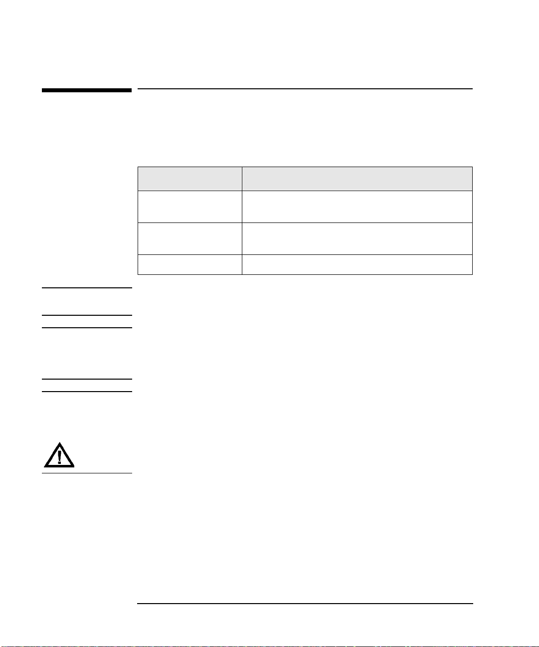
Figure 1-1 Rear Panel Features
The following li st identifies the numbere d components in Figure 1-1:
1 Bus 1 SCSI ports
2 SCSI interface mode switch
3 Bus 2 SCSI ports
4Power port
5 SCSI bus indicator label
6 SCSI bus status indicators
1-6
Page 21

Installing the Tape Library
Step 3: Install the Host SCSI Card(s)
Step 3: Install the Host SCSI Card(s)
Install the si ngle-ended or differential SCSI card into the host computer system.
Refer to the host user manual and the SCSI card installation instruct ions for
information on installing and configuring SCSI cards.
Installation
1-7
Page 22

Installing the Tape Library
Step 4: Mount the Library in a Rack (optional)
Step 4: Mount the Library in a Rac k (opti onal)
For stand-alo ne ins talla tions , go to “St ep 5: Set the SCSI Inte rface Mode Swit ch” on
page 1-20.
The rack slides can be adjuste d to fit any standard rack with a depth of 26 to 31
inches (66.04 to 78.75 centimeters).
Safety Precautions
Because the ta pe library weighs approximately 100 pounds (45 kilograms), the
following safe ty precautions must be tak en when mounting the tape librar y:
• Full y extend the rack’s antitip rail and lower the leveller feet.
• Mount the tape library no higher than 4 fee t (122 ce ntimeters) in the rack.
• IMPORTANT: At least two people must lift the library during installation.
WARNING Do not pull the library out of the rack to its fully extended position unless the
anti-tip rail on the bottom of the rack has been positioned correctly. Do not
attempt to move the tape library by yourself.
The tape librar y weighs approximately 100 pou nds (45 kilograms). Pulli n g the
librar y out of the rack wit ho u t th e ra ck’s anti-tip ra i l ex t ended could result in
personal injury and/or damage to the tape library if the rack tips over.
1-8
Page 23
Installing the Tape Library
Step 4: Mount the Library in a Rack (optional)
Tools and Comp onents
Tools:
Phillips screwdriver (included in ki t)
1/2 inch open-ended wrench
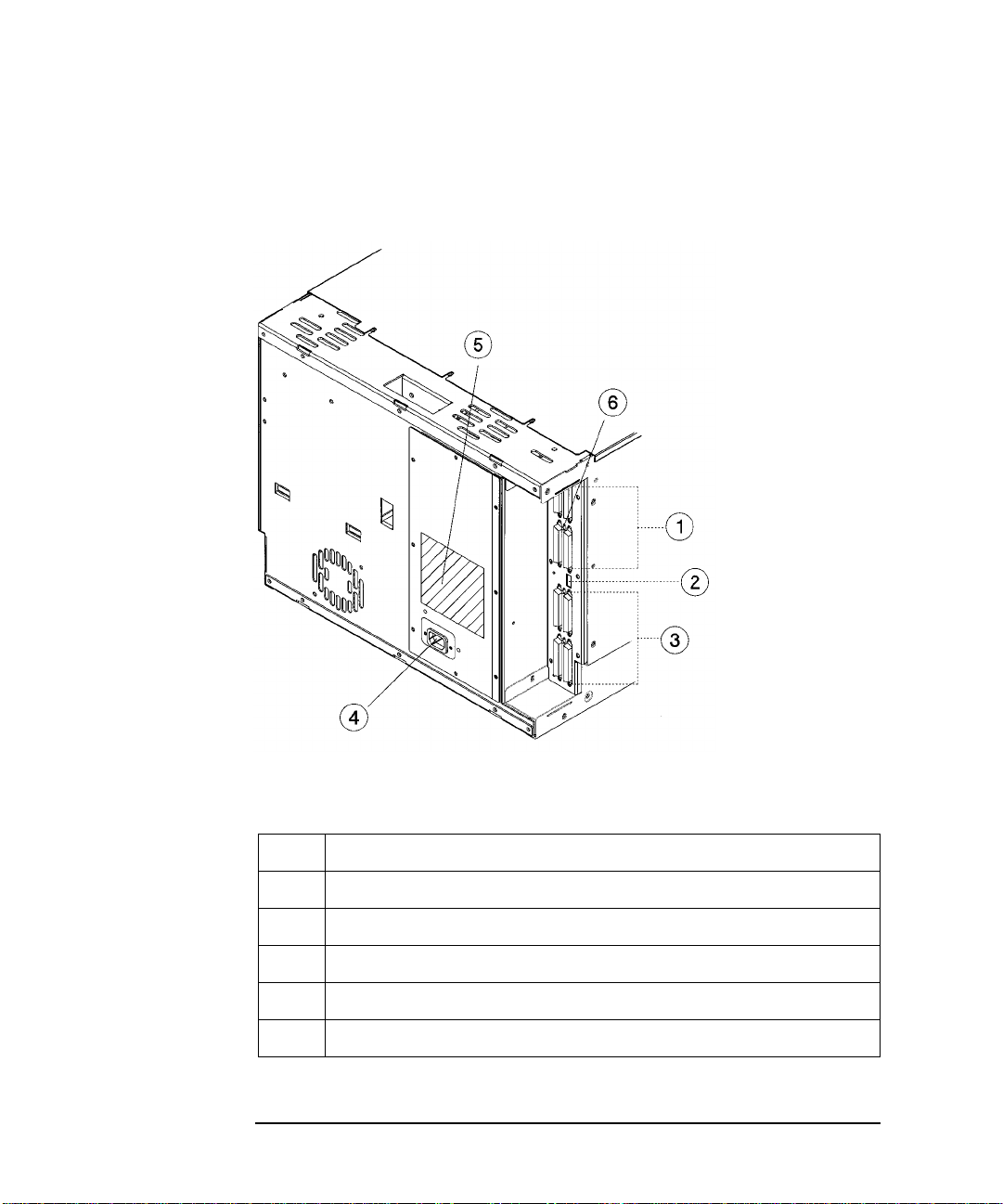
Kit Hardware (parts are labeled for easy identification):
1. rack slides (1 pair)
2. bezel spacers (2)
3. mounting brackets (4)
4. strain relief bracket (1)
5. cable ties (4)
6. template
Figure 1-2 Rackmounting Componen ts
Installation
7. 8-32 x 3/8 pan slotted phillips lw profile
hd (14)
8. 10-32 x 5/8 pan slotted phillips (14)
9. 10-32 clip nuts (12)
10. 8-32 keps nuts (8)
11. 6-32 x 3/8 pan phillips, with internal
lockwasher (1)
1-9
Page 24
Installing the Tape Library
Step 4: Mount the Library in a Rack (optional)
Mounting the L ibr ar y
To mount the tape library in a rack, you must:
• First, attach the front and back mounting brackets to the rack s lides.
• Next, attach the rack slides to the rack.
• Finally, attach the tape library to the rack slides.
These steps are explained in detail in the following sections.
Attach the Mounting Brackets
1. IMPORTANT: Lower the rack’s leveller feet using a 1/2-inch open-end wrench,
and extend the rack’s antitip rail.
WARNING Failure to extend the antitip rail could result in personal injury and/or damage
to the tape library if the rack tips over.
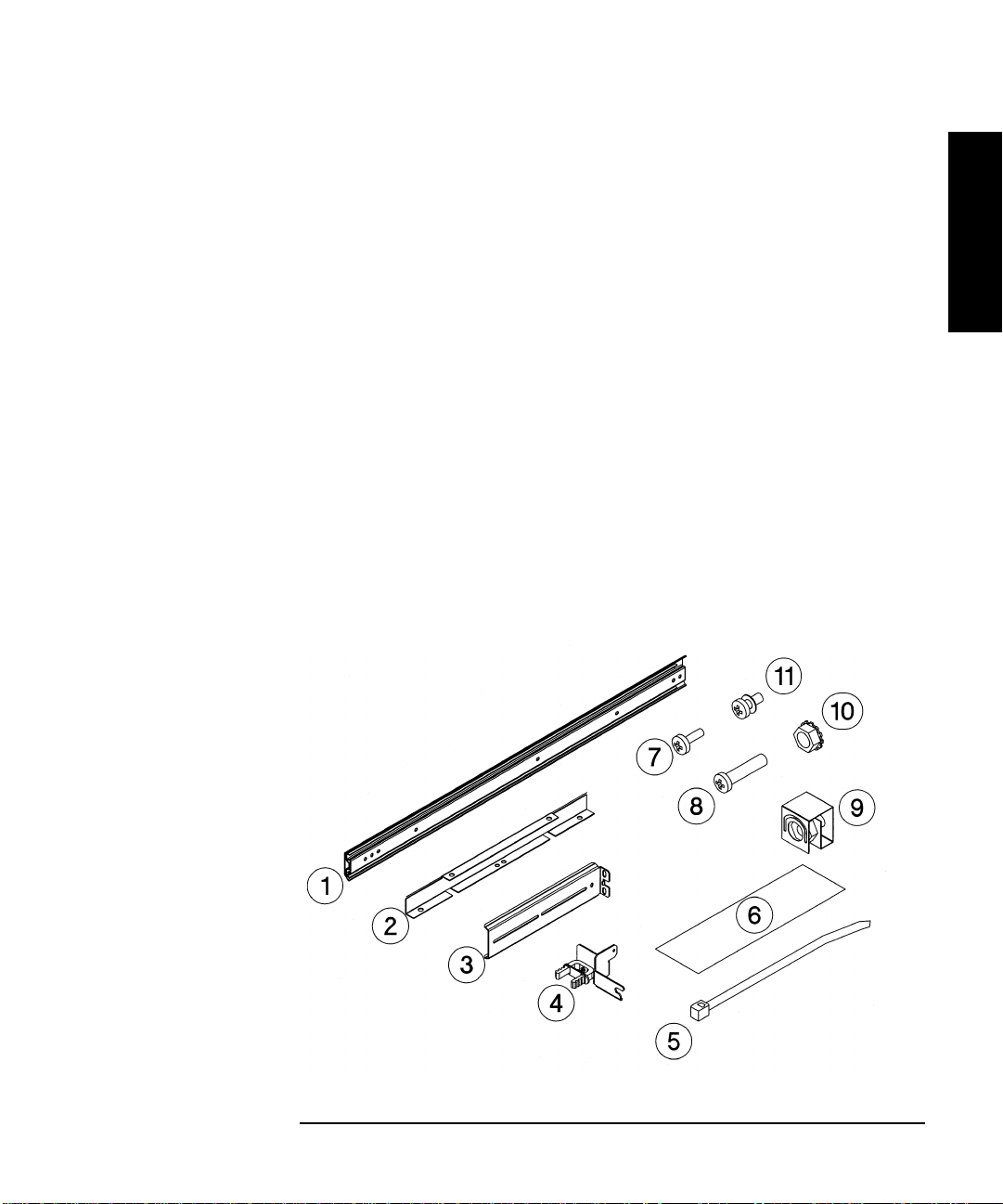
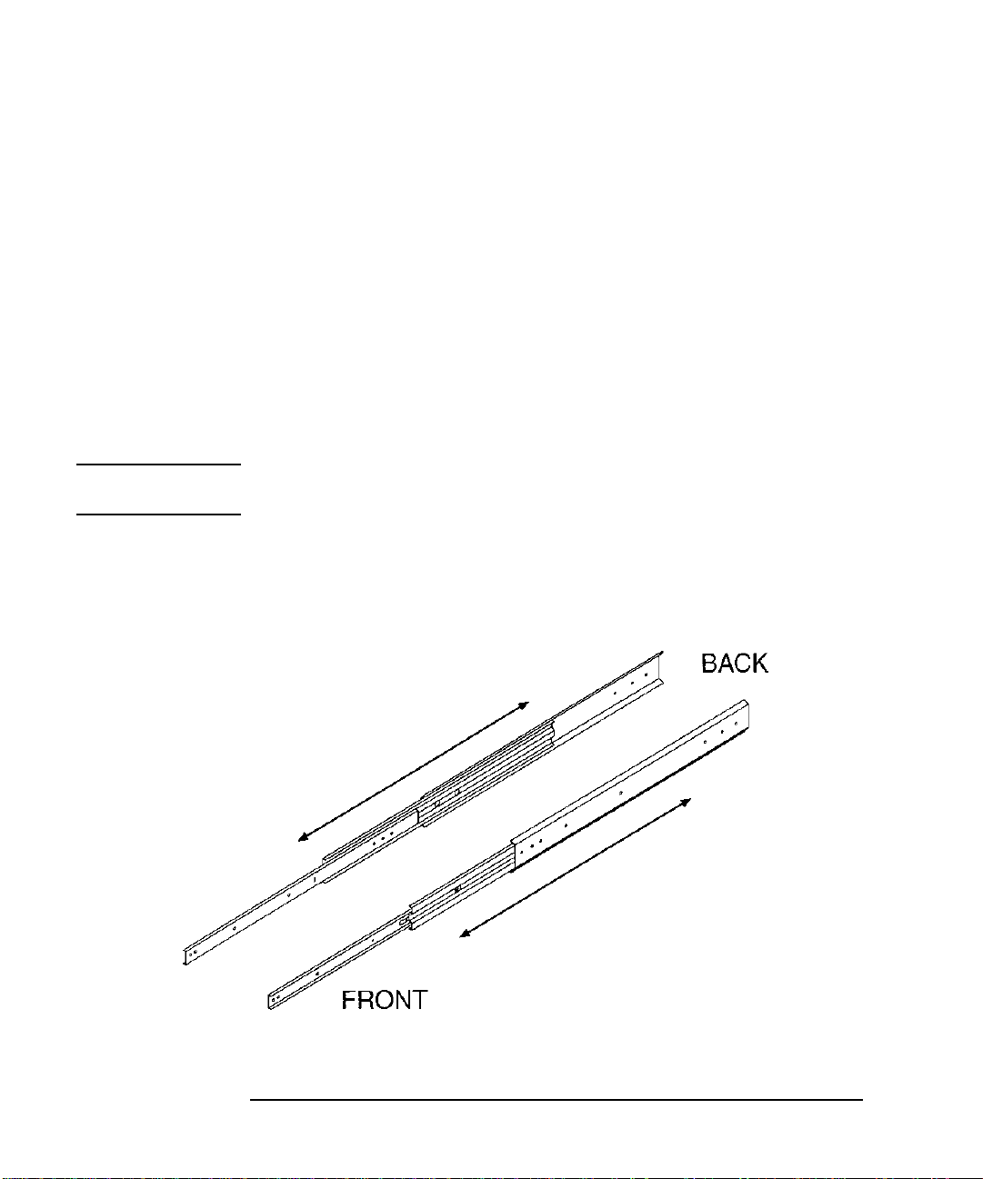
2. Pull th e r ack slide members out to the fully exten d ed p o sition. (The sli d es
should “click” into a locked positi on.)
Figure 1-3 Rack Slides
1-10
Page 25

Installing the Tape Library
Step 4: Mount the Library in a Rack (optional)
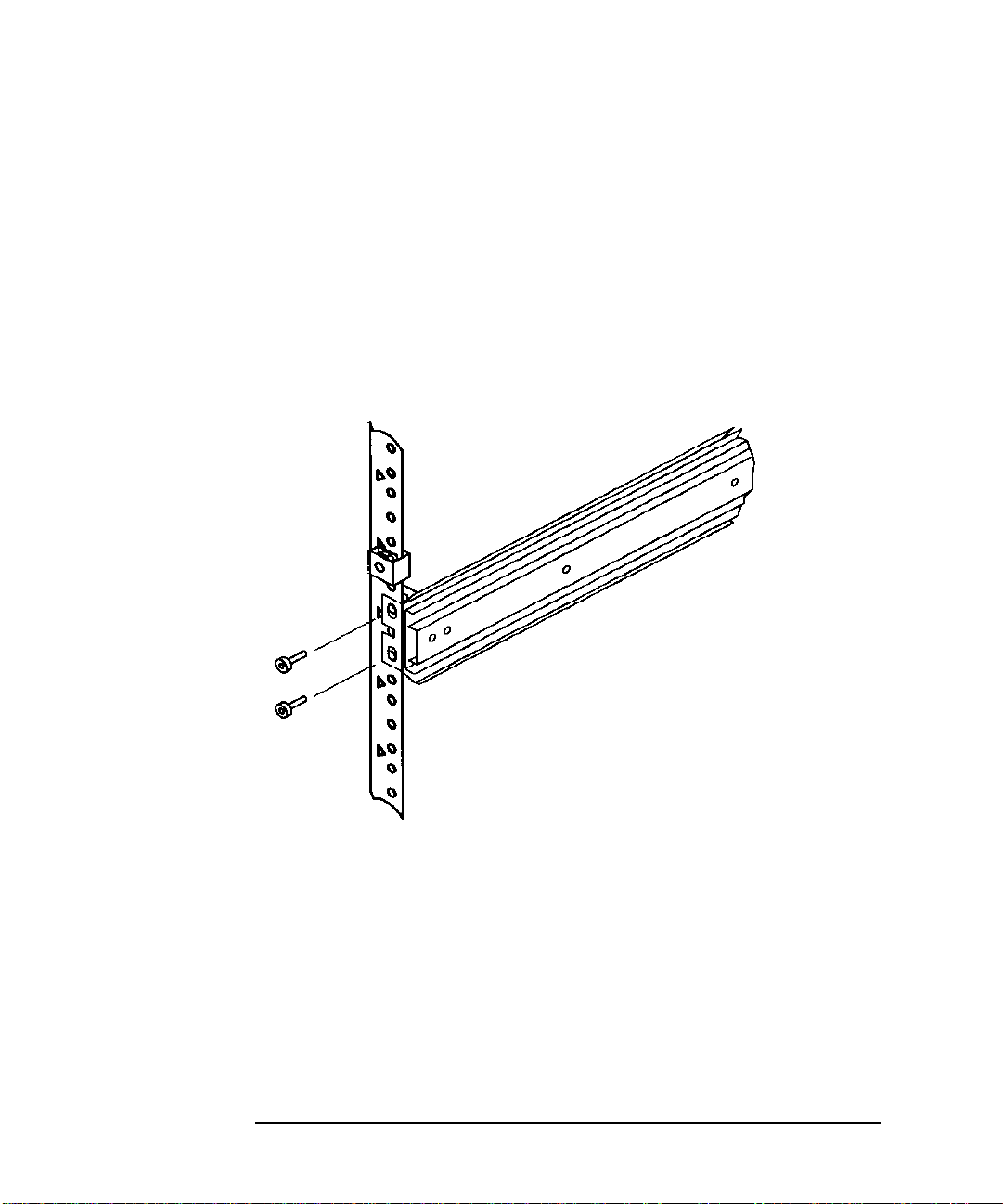
3. Attach the front mounting brackets to the front end of each s lide using two 8-32
x 3/8 pan-slotted phillips screws and two 8-32 keps nuts. Tighten the screws.
Figure 1-4 Front Mounting Bracket
4. Attach the rear m ounting b rac kets to the b ack s ide of eac h slid e usin g two 8- 32 x
3/8 pan-slotted phillips screws and two 8-32 keps nuts. Do not tighten the
screws.
Installation
Figure 1-5 Rear Mounting Bracket
1-11
Page 26
Installing the Tape Library
Step 4: Mount the Library in a Rack (optional)
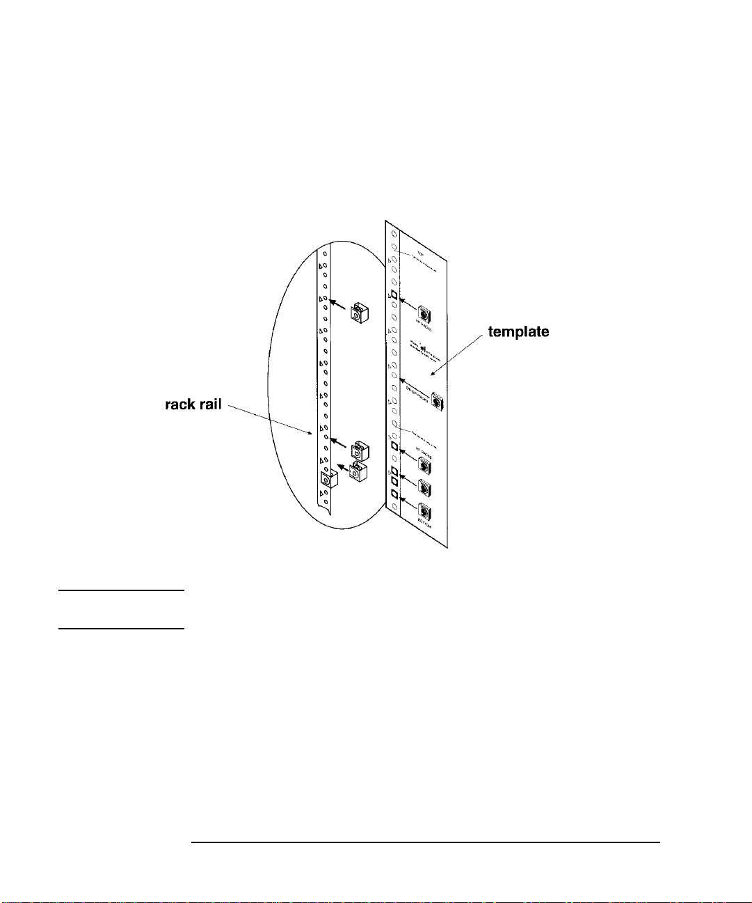
Attach the Rack Slides to the Rack
1. Line up the templat e with an existing pr oduct in the rack. Attach clip nuts to
each front rail in the locations indicated on the template.
Figure 1-6 Clip Nuts (Front Rails)
NOTE Do not install the library in the bottom of the rack. Make sure the bottom of the
library is no higher than 4 feet off the floor.
1-12
Page 27

Installing the Tape Library
Step 4: Mount the Library in a Rack (optional)
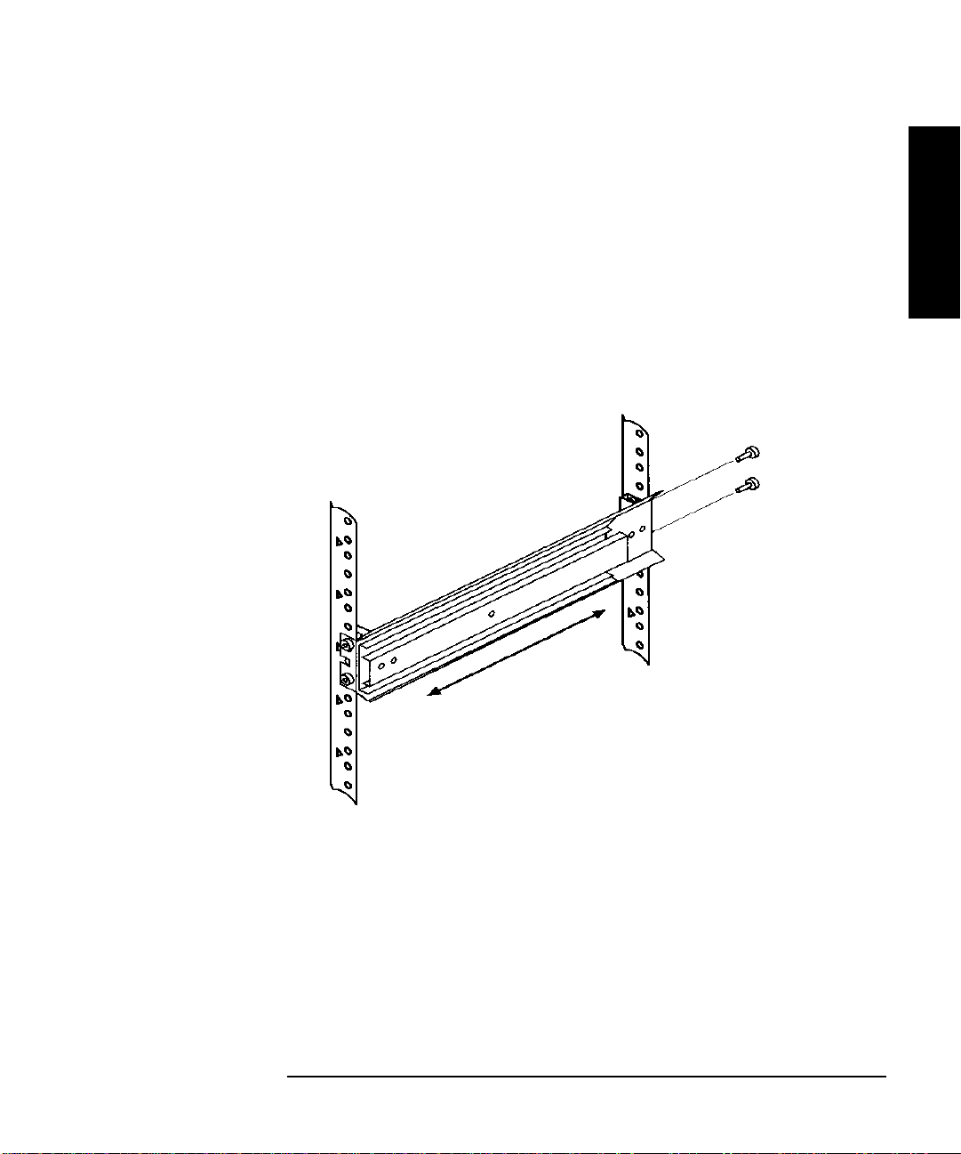
2. Attach two cl ip nut s to ea ch of th e ba ck ra ils s o that the slid es will be leve l when
attached to the rails.
NOTE Count the holes on the front and back rails to ensure the slides will be level.
Figure 1-7 Clip Nuts (Back Rails)
Installation
1-13
Page 28
Installing the Tape Library
Step 4: Mount the Library in a Rack (optional)
3. Attach the front bracke t:
a. Return the slides to their compressed position.
b. Attach the front slide mounting bracket to the lower two clip nuts on the
front rails using two 10-32 x 5/8 pan slotted phlp sc rews.
c. Pu s h th e sli d es as f ar as po s s ib le toward th e o utside of th e rack.
d. Tighten the screws .
Figure 1-8 Front Bracket on Rack
1-14
Page 29
Installing the Tape Library
Step 4: Mount the Library in a Rack (optional)
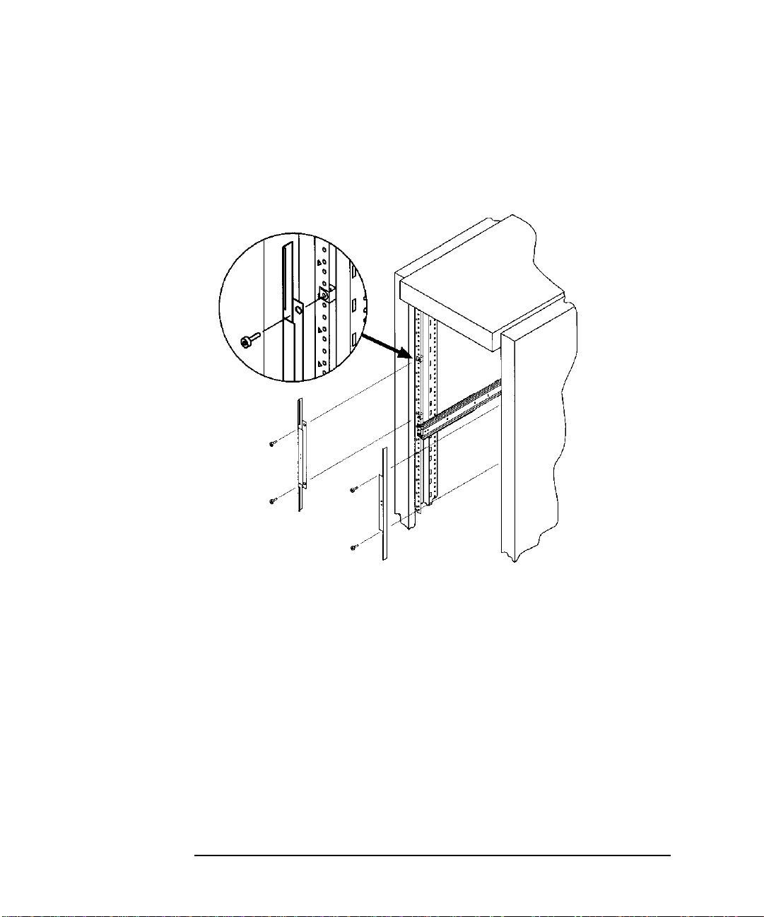
4. Attach the rear bracket:
a. Adjust the re ar mounting brackets to fit lengthwise in the rack.
b. Attach the rear sli de mountin g brac ket to the rea r clip nut s usi ng two 10-32 x
5/8 pan slotted phlp screws.
c. Pu s h th e sli d es as f ar as po s s ib le towa rd th e o utside of th e rack.
d. Tighten the screws .
e. Tighten all bracket screws.
Figure 1-9 Rear Bracket on Rack
Installation
5. Extend the slides fully, make sure they are parallel, and then recompress them.
1-15
Page 30
Installing the Tape Library
Step 4: Mount the Library in a Rack (optional)
6. Connect the two bezel s pacers t o the fron t rails us ing two 10-32 x 5/8 p an slo tted
phlp screws. The screws attach to the two clip nuts on the front rails above the
slides.
Figure 1-10 Bezel Spacers
1-16
Page 31

Installing the Tape Library
Step 4: Mount the Library in a Rack (optional)
Place the Library in the Rack
1. Attach the cable strain relief bracket to the library rear panel below the SCSI
connectors using one 6-32 x 3/8 pan phlp, with internal lockwasher screw.
Figure 1 - 11 Strai n Re lief Brack e t
Installation
2. Ensure that the r ack’s anti-tip rails are extended.
WARNING Failure to extend the rack’s anti-tip rail could result in personal injury and/or
damage to the tape library.
3. Remove the keys from th e library handle.
4. Important – two people needed: Lift the library onto the slides and back slightly
into the rack using the side handles. Make sure the handl es si t securely on the
slides and that the front hol es in t he libra ry li ne up with the second hole from the
fron t on the sl id es.
WARNING Do not attempt to move the tape library by yourself.
The tape librar y weighs approximately 100 pou nds (45 kilograms). To avoid
personal injury and/or damage to the tape library, a minimum of two people
are needed to mo v e the li b r ar y.
1-17
Page 32

Installing the Tape Library
Step 4: Mount the Library in a Rack (optional)
5. Attach the library to each slide using three 8-32 x 3/8 pa n-slotted phillips
screws.
Figure 1-12 Library on Slides
6. Remove the insta llation handles by re moving two screws on each handle. Keep
the screws and handles in ca se the library needs to be reshipped in the future.
Figure 1-13 Installation Handles
1-18
Page 33

Installing the Tape Library
Step 4: Mount the Library in a Rack (optional)
7. Release the slide latch springs, then push the tape library into the rack.
8. Open the front access door using the key, and secure the library to the rack
through the rectangular holes in the door using two 10-32 x 5/8 pa n sl otted phlp
screws.
Figure 1-14 Front Access Door
Installation
1-19
Page 34

Installing the Tape Library
Step 5: Set the SCSI Interface Mode Switch
Step 5: Set the SCSI Interface Mode Switch
Do not connect any cables yet.
The SCSI interface mode switch, shown below, is on the rear panel between the bus
1 and bus 2 SCSI ports.
Figure 1-15 SCS I Interface Mode Switch (Example)
To set the SCSI interface mode switch:
1. Determine how to connect the library accordin g to:
• Number of drives in the library and drive type
• Other peripherals (if any) on your system
• Type of SCSI card (differential or single-ended)
NOTE For best library performance, connect only one library on a SCSI bus.
2. Set the SC S I in t e r f ace mod e s w it ch.
Table 1-4 SCSI Interface Mode Switch Settings
Setting Purpose Set to
Term Pwr Sends power to the termi nator. ON in most installations
T er minat ion T ermina te s the SCSI bus . Fun ctions t he
same as a physical terminator.
DIFF/SE Specifies whether you are using the
differential or single-ended port.
1-20
ON if the tape driv e is the last device
on the SCSI chain
OFF if anothe r peripheral wi ll conn ect
to the lib r ar y
DIFF for differential
SE for single-ended
Page 35

Installing the Tape Library
Differential SCSI
Step 5: Set the SCSI Interface Mode Switch
The following table shows connection opti ons when there are no other peripherals.
Table 1-5 Tape Library as the Only Peripheral
Configuration Cabling Mode Switch Settings
One-Drive Tape
Library
Single-ended SCSI
connection
Two-Drive Library:
Daisy chained
Minimum host I/O
Single-ended
SCS I co nnection
shown
slots used
Installation
Two-Drive Library
Bus 1 and bus 2
connect to sepa rate
SCSI cards
Maximum
performance
Additional ca rd and
cable requ ir e d
connection shown
1-21
Page 36

Installing the Tape Library
Single-ended SCSI
Single-ended
Step 5: Set the SCSI Interface Mode Switch
The following table shows connection opti ons when there are other peripherals.
Table 1-6 Tape Library with Other Peripherals
Configuration Cabling Mode Switch Settings
One-Drive Tape Library:
Library on its own bus
connection shown
Maximum performance
One-Drive Tape Library:
Daisy chained to
peripheral
connection shown
SCSI
Minimum host I/O slots
used
bus 2 not us ed
Two-Drive Library:
Daisy chained lib rary and
peripheral
Minimum host I/O slots
used
Two-Drive Library: bus 1
and bus 2 use separate
SCSI cards
Additional c ard and c able
required
Minimum I/O slots used
1-22
EXVQRWXVHG
Page 37

Installing the Tape Library
Step 6: Connect Library to Host
S t e p 6: Connect Library to Host
Do not turn on the host system or library yet!
1. Properly shut down all pe ripheral devices connected to the host compute r.
If the ho st computer is connected to a network, be sure to check with the system
administrator before switching off power.
2. Switch off power to the server.
3. Connect the SCSI cables.
Before you set the mode swit ch, you determined how to config ure your SCSI
bus (see the connection diagrams on page 1-21 and page 1-22). Using this
configurat ion, connect the library to the host. Make sure :
• You use the proper port (single-ended or differential).
• The last device in the SCSI bus is termina ted.
4. Make sure the power switch on the library front panel is s witched off.
Installation
5. Plug the power cord into the power port on the back of the library.
Stand-alone installations: Go to “Step 7: Power On the System” on page 1-27.
Rack mount installations: Go to th e next section, “Routing SCSI and Power Cables
on Rack Mounted Libraries.”
Routing SCSI and Power Cables on Rack Mounted Libraries
CAUTION SCSI and power cables must be routed and secured properly on rack mounte d
libraries . Failure to properly route library cables could result in damage to the
cables.
To properly route an d secure rack mounted libr ary power and SCSI cables:
1. Route the SCSI/power cables through the strain relief bracket:
a. Squeez e the two plastic ends of th e cable strain relief brack et together.
b. Pull off the plas tic strain relief clamp.
1-23
Page 38

Installing the Tape Library
Step 6: Connect Library to Host
c. Route the SCSI cable(s) and the power cord through the cab le strain relief
bracket.
d. Slide the strain relief clamp back onto the bracket.
e. Attach a cable tie (included in the rack mount kit) to the SCSI and power
cables ab out eight inches back from the strain r elief bracket.
f. Attach another cable tie about eight inches back from the first cable tie.
Figure 1-16 SCSI/Power Cables an d Strain Relief Bracket
2. Exte nd th e rack’s anti-tip rail an d ver i f y th a t th e levell e r feet are dow n .
WARNING Failure to extend the antitip rail could result in personal injury and/or damage
to the library if the rack tips over.
1-24
Page 39

Installing the Tape Library
Step 6: Connect Library to Host
3. Use the key to open the front access door. Remove the two screws that secure
the library to the rack.
Figure 1-17 Front Access Door
Installation
4. Slide the library out of the rack so that it is in the fully extended position.
1-25
Page 40

Installing the Tape Library
Step 6: Connect Library to Host
5. Gently pull the SCSI and power cables back toward the rear of th e rac k. Use a
cable tie to secure the m to the rail at the ba ck of the ra ck. The cabl e ti e shoul d be
at about the same height as the top of the library.
6. Carefully route th e ca bles down along the back rail. Use a cable tie to secure
them to the rail just above the slide mounting bracket. Clip off the ends of all
four cable ties.
Figure 1-18 Sec ured SCSI and Power Cables
7. Close the back door on the rack.
8. Push the library back into the rack.
9. Open the front access door . Replace the two s crews that sec ure the library t o the
rack, then re-lock the door.
1-26
Page 41

Installing the Tape Library
Step 7: Power On the System
Step 7: Power On the System
1. Plug the power cord into a grounded outlet.
2. Turn on the power switch.
Initially SELF TEST and NOT READY, and then NOT READY and INVENTORY
CHECK alternately appe ar in the display window on the li brary. After the
power-on test completes (approximately 1.5 minutes), the drive status
information displays. (See “Understanding Display Window Messages” on
page 3-4.)
NOTE If the drive status in format ion doe s not displ ay, the power-on test wa s not succes sful
and DEVICE FAILED displays. See “Troubleshooting ” on page 3-38 for
troubleshooting procedures.
3. Turn on other per ipherals (if any).
4. Turn on the host sy stem.
Installation
Insta l l Backup Sof t w are
Follow the instructions provided with your backu p soft ware to configure it to your
library. Several trial versions are provided with the library for your eva luation.
Verify Installation With TapeAssure
HP TapeAssure is a software utility that tells you quickly and e asily whether your
configuration is correct and whether the ta pe drive is ready for use with backup
software. Your backup software must be TapeAlert compatible for you to receive
these messages (compatible packages will display the HP TapeAlert logo). For the
latest list of backup packages that support TapeAlert, refer to HP’ s W orld Wide
Web site (http://www.hp.com/go/t ape ).
1-27
Page 42

Installing the Tape Library
Moving or Shipping the Library
Moving or Shipping the Library
This section explains how to move the li brary a short distanc e, such as to another
office or to another floor in the building and how to ship the library to anot her
location.
WARNING The library weighs appr oximately 100 pounds (45 kilograms). To avoid
personal injury and possible damage to the library, at least two people must
move the library.
To move or ship the li brary:
1. Properly shut down and power off the host.
2. Unmount (unreserve) any tap e cartridges in the library if necessary. See your
computer operating system documentation, or software application
documentation for ins tructions on how to unmoun t tape cartridges.
3. Verify that al l d riv es in th e lib r ar y ar e empty:
If the drives are full, empty them before shipping the libra ry. (For instructions,
refer to the software doc umentation your host system uses to manage the
library.)
4. Switch off the power s witch on the library front panel.
CAUTION Do not switc h off power to the library until the SCSI bus is inactive.
Removing power from a SCSI peripheral when the bus is active can result in data
loss and/or indeterminate bus stat es. (Check your host system manua ls for
information about checking the SCSI bus status.) If your com puter is connected to a
LAN, be sure to check with your system admin istrator before shutti ng off power to
the library.
5. Remove the power cord and the SCSI cable connections from the library rear
panel.
1-28
Page 43

Installing the Tape Library
Moving or Shipping the Library
6. If the library is rack mounted:
a. Extend the anti-tip rail on the rack.
WARNING Failure to extend the anti-tip rail could result in personal injury and/or damage
to the library if the rack tips over.
b. Slide the library out of the ra ck so that it is in the fully extended position.
c. Reattach the handles to the side of library using two screws. Make sure the
handle flanges are on top of the slides. (The handles and hardware for
reattaching them should have been saved with the original shipping
materials. If they are missing, call your service representative to order
replacement handles.)
d. Remove the three 8-32 screws on each s ide of the library that secu re the
library to the rack slides.
e. IMPORTANT — two people needed: With a person on each si de of the
library, lift the library onto a ca r t.
7. Transport the library:
• To move the library a short distance, roll the cart to the new location.
• To ship the library, repackage the library in the same materials and ship it in
the same manner in which it was received.
Installation
CAUTION The library can be seriously damaged if it is not shipped usi ng appropriate shipping
materials. A service representati ve ca n provide assistance or advice on how to best
repackage and ship the library .
8. Re-insta ll the libra r y. Refer to installation steps in this chapter.
1-29
Page 44

Installing the Tape Library
Moving or Shipping the Library
1-30
Page 45

Using Tapes
2 Using Tape Cartridges
2-1
Page 46

Using Tape Cartridges
Tape Cartridge Overview
Tape C artridge Overvi ew
The tape cartrid ges you use in the tape drive are an integral part of the storage
process. This chapter explains how to:
• Choose a tape cartridge.
• Label tape cartridges with bar code labels.
• Label bulk load magazines .
• Interpret drive cleaning messages.
• Write-protect a tape cartridge.
• Maintain a tape cartridge.
NOTE For top per formance an d r eliability, Hewlett Packard recommends HP-labeled tape
cartridges that have been fully tested for use with HP’ s tape products. Purcha se
these cartridges through any HP-authorized dealer, or order them through HP
Direct. See “Supplies and Accessories” on page A-3 for ordering information.
2-2
Page 47

Using Tape Cartridges
Choosing Tape Cartridges
Choosing Tape Cartridges
Two types of compatible digital linear tape cartridges are avail able:
Table 2-1 Supported Tape Types
Cartridge Type Available Densities
HP DLTtape IV Data Cartridge 20 GBytes uncompressed
(DLT4000 drive)
35 GBytes uncompressed
(DLT7000 drive)
HP DLTtape III XT Data Cartridge 15 GBytes uncompressed
NOTE Hewlett-Packard recommends using the HP DLTtape IV Data Cartridge for top
performance, hi ghes t capacity, and least amount of head cleaning.
Using Tapes
Using Tape Cartridges
2-3
Page 48

Using Tape Cartridges
Labeling Tape Cartridges
Labeling Tape Cartridges
Make it a practice to use bar code labels on your tape cartri dges. Your host software
may need to keep track of the following information and the associated bar c ode:
• date of format or initialization
• cartridge owner (such as group or de partment)
• storage purpose (such as backup, old version of operating system)
If the host sof tware does not keep t rac k of this inform ation , crea te a me thod of doing
so.
Slide th e label in to the sl o t on th e face of th e ca r t ri d g e as il lustrated in Figure 2-1 .
NOTE If bar code labels are not us ed and the “Barcode On/Off” configuration is se t to
“Off,” the Invent ory Che ck te st per formanc e can be signifi cantl y i mpact ed. This tes t
runs when the library is powered on and whenever the front acces s door is opened.
See Appendix A for information about ordering additional bar code labels.
Figure 2-1 Proper Label Position
2-4
Page 49

Labeling Bulk Load Magazines
Bulk load magazines can be labeled in a manner s imilar to tape cartridges.
To label bulk loa d ma gazines:
1. Clean the magazine surface with isopropyl alcohol (optional, but
recommended).
2. Remove the adhesive backing from the label pouch.
3. Apply the pouch to the magazine anywhere within the shaded a r ea shown in
Figure 2-2.
4. Slide the labe l into the pouch.
Figure 2-2 Magazine Label Position
Using Tape Cartridges
Labeling Bulk Load Magazines
Using Tapes
Using Tape Cartridges
2-5
Page 50

Using Tape Cartridges
Drive Cleaning Messages
Drive Cleaning Messages
Ta ble 2-2 lists drive cleaning messages that might be caused by a tape. Note that:
• The tape drives do not require sc heduled clea ning m ainte nance . Ex cessi ve us e of
the cleaning c artridge can cause unnecessary wea r on the drive head.
• After 20 cleaning cycles, the cleaning cartridge must be replaced.
NOTE For drive cleaning instructions, refer to “Clea ning the Library Tape Drives” on
page 3-23.
2-6
Page 51

Table 2-2 Drive Cleaning Messages
If this happens: Reason: You need to:
Using Tape Cartridges
Drive C lea n i ng Messag es
A brand new tape
cartridge is used
and a drive
cleaning message
is received.
An older,
frequently used
tape cartridge is
loaded an d a driv e
cleaning message
is received.
An older,
frequently used
tape ca us es a
cleaning message
to be displayed for
the second time .
Debris from the
tape manufacturi ng
process was
deposited on the
drive head.
Dust from frequent
tape loads and
unloads has
probably built up
on the tape
cartridge and wa s
deposited on the
drive head.
The tape is
probably damaged.
(Damag ed
cartridges can
cause unnecessary
use of the cleaning
cartridge.)
Clean the drive using the tape li brary cleaning procedure in
“Cleaning the Library Tape Drives” on page 3-23.
If the message is displ ayed again within a short amount of
time, re pl ace the car t ri d g e.
Clean the outside of the tape cartridge with a damp cloth.
Clean the tape drive using the ta pe drive cleaning procedure
in “Cleaning the Library Tape Drives” on page 3-23.
1. Verify the tape is readable by clearing the error message.
(Select the ONLINE REPAIR option from the control
panel. Turn off the drive containing the tape. Turn the
drive on again. (See “Using Online D rive Replacement”
on page 3-36).
2. Try reading the tape again:
• If the tape can be read, back up data from the
damaged cartridge to another tape cartridge and
discard the dama ged one.
Using Tapes
Using Tape Cartridges
• If the tape cannot be read, call service.
2-7
Page 52

Using Tape Cartridges
Write-Protecting Tape Cartridges
Write-Prot ecting Tap e Cartridges
The use of the write protect swi tch ensures data safety for files that have been
previously wri tten to t he tape and preven ts any addit ion al file s from being wri tten to
the tape.
To change the write-protect setting, move the write-protect switch:
•Left to prevent data from being written to the cartri dge. The ora nge indi cator on
the cartri dge can be seen when the write-protect switch is in the “ON” position
(see “A” in Figure 2-3).
• Right to allow data to be written to the cartridge. The orange indicator on the
cartridge cannot be seen when the write-protect switch is in the “OFF” position
(see “B ” in Fig u r e 2 - 3).
With the write-protect switch in either position, data can be read from the cartridge.
Figure 2-3 Write-Protect Button Settings
Write-Protected
Not Write-Protected
2-8
Page 53

Maintaining Tape Cartridges
Ta ble 2-3 Tape Cartridge Maintenance
Using Tape Cartridges
Maintaining Tape Cartridges
DO NOT: DO:
• Expose cartridges to magnetic fields.
• Leave cartridges in the tape drive
when library power is off.
• Expose cartridges to extreme
tempe r at u r es o r extreme hum i d it y.
Acceptable opera ting temperatures
range from 10-40° C (50-104° F).
Acceptable storage temperatures
range from 16-32° C (60-90° F).
Acceptable opera ting humidity
ranges from 20-80%; acceptable
storage humidity ranges from
10-95%.
• Expose cartridges to moisture or
direct sunlight.
• Drop the cartridges or c arry t hem i n a
loose container that could submit the
cartridges to any unnecessary
physical shock.
• Open cartridges lid, exposing the
tape to pos sible contamination or
physical damage.
• Store cartridges in a clean, safe
place in their protective plastic
containers when not in us e.
• Remove dust on the outside of
cartridges us ing a damp cloth.
(Older, frequently used ta pes
may build up dust.)
• Store cartridges vertically, not
flat.
• Store cartridges intended for
archiving data in their plastic
containers and in environmental
conditions of 18-28° C (64-82°
F) and 40-60% relative
humidity.
• Use labels like th ose inc lud ed in
the accessories kit or tha t meet
the specifications listed in Table
A-1 on page A-3.
Using Tapes
Using Tape Cartridges
• Touch the tape surface.
• Take cartr i d ge s ap ar t .
• Use graphite pencils, water soluble
felt pens, or other debris -producing
writing instruments to label
cartridges.
• Erase a label; replace it instead.
2-9
Page 54

Using Tape Cartridges
Maintaining Tape Cartridges
2-10
Page 55

3 Operating the Library
Library Operation
3-1
Page 56

Operating the Library
Overview
Overview
This chapter explains the following li brary operations:
• “Operating the Control Panel” on pag e 3-3
• “Understanding Display Window Messages” on page 3-4
• “Entering the Administration Menu Password” on page 3-9
• “Setting a New Adminis tration Menu Password” on page 3-10
• “Setting and Viewing SCSI IDs” on page 3-11
• “Loading Tape Cartridges Into theLibrary” on page 3-15
• “Removing Ta pe Cartridges from the Library” on page 3-19
• “Viewing Cartridge Bar Code Labels” on page 3-22
• “Cleaning the Library Tape Drives” on page 3-23
• “Using Online Drive Replacement” on pa ge 3-36
• “Setting Configuration Options” on page 3-25
• “Retrieving Performance Information” on page 3-28
• “Running an Internal Test” on page 3-32
• “Using Online Drive Replacement” on pa ge 3-36
• “Troubleshooting” on page 3-38
3-2
Page 57

Operating the Control Panel
Figure 3-1 Tape Library Control Panel
1. Selection buttons allows you to perform the following operations:
Operating the Library
Operating the Control Panel
Library Operation
CANCEL cancels the current operation or option.
•
PREV scrolls the display options backward by one. When held continuously,
•
the options scroll quickly.
NEXT scrolls the displ ay options forward by one. When held continuously,
•
the options scroll quickly.
ENTER selects the displayed option.
•
2. Activity light indicates the following:
• Steady Green – power is on.
• Flashing Green – a tape cartridge is being accessed.
• Amber – fault indicator.
3. 16-Character Display displays information about the current operation or drive
status. An asterisk (*) indi cates there is a menu beneath the option. Press
to acces s the menu. Press
NEXT or PREV to display the menu options.
ENTER
4. Power switch switche s powe r to the unit on and off.
5. Door latch locks/unlocks door for access to bulk load magazines.
3-3
Page 58

Operating the Library
Understanding Display Window Messages
Understanding Display Window Messages
The display window displays drive status indicators and menu options.
Drive Status
The following fig ure s hows the drive status indicators displaye d when the library is
in the “re ad y ” s t at e.
In this example:
1. Drive 1 has a cartridge inserted and data is being written to the tape.
2. Drive 2 has a write-protected cartridge inserted.
S tat us Indic ator s
Status in dicat ors provi de drive status informatio n for the drive numbe r that pre cedes
one of the following indicators.
The dri v e is full.
The dri v e is empty.
The drive needs to be cleaned.
The tape cartridge in the drive is write-protected.
3-4
Page 59

Understanding Display Window Messages
Activity Indicators
The activity light flashes during the following operations:
Information is being writte n to the tape in the drive.
Information is being read to the tape in the d rive.
The tape in the drive is being searched back ward or is rewinding.
The tape in the drive is being seached forward.
The drive is b ei n g cl ea n ed .
Operating the Library
Library Operation
3-5
Page 60

Operating the Library
Understanding Display Window Messages
Control Panel Options
Press PREV or NEXT while the library is in the “ready” state to display first-leve l
options. Access second-l evel options from ADMIN * (second level options req uire a
password; see “En tering the Administration Menu Password” on page 3-9).
An asterisk (*) indica tes that the opti on has multiple se lections.
When a menu s election is flashing, press
option’s selections. Press
PREV or NEXT to display othe r available options.
ENTER to select the option or display the
First Level Options
RELEASE DOOR Select to allow the access door to be unlocked.
VIEW BAR
CODES *
ADMIN * Accesses second-level options.
LOAD DRIVE * Loa d s a tape from a slot to the drive. To load a tape:
UNLOAD DRIVE * Un loads a tap e from th e d r iv e to th e sl o t it came from.
Select to view the bar code labels on each tape cartrid ge
by slot number.
1. Select the drive tha t you want to load a tape into.
2. Select the ta pe that you want to load. The control
panel displays the barcode number and slot numb er.
PREV or NEXT to select, then ENTER.
Press
3. The control panel displays the drive it is loading to.
TAPE LOADED displays when complete.
1. Press
PREV or NEXT to select the drive that you want
to unlo ad . P res s
ENTER. If a tap e is n ot in the dri ve,
SOURCE IS EMPTY displays.
2. The activity light flashes green and TAPE
UNLOADED flashes when complete.
3-6
Page 61

Operating the Library
Understanding Display Window Messages
Second Level Options
INFO * Displays performance information stored in the library.
TEST * Runs internal library tests.
CONFIG * Customizes the way the library functions .
CLEAN DRIVES * Displays the drive numbers you wish to clean.
OVERRIDE DOOR * Open s the door when media is in drives.
SCSI IDs * Sets the SCSI addresses for the robotics and the library
drives.
ONLINE REPAIR * De-activates a drive for replacement.
Library Operation
3-7
Page 62

Operating the Library
Understanding Display Window Messages
Control Panel Menu Tree
Figure 3-2 Control Panel Menu Optio ns
3-8
Page 63

Operating the Library
Entering the Administration Menu Password
Entering the Administration Menu Password
1 2 → ADMIN * → CONFIG *
A numeric password is required to access options beneath ADMIN* menu of the
library (see Figure 3-2 on page 3-8). A three-part default password of 000-000-000
is set at the factory. To change the password, see “Setting a New Administration
Menu Password” on page 3-10.
To enter the passw o r d :
Library Operation
1. Verify that the drive status displays. If it does not displa y, press
does.
2. Press
NEXT until ADMIN * displays, then press ENTER.
3. PSWD 000-000-000 displays, and the first set of zeros flashes.
ENTER to accept this number (if no password has been set), or press NEXT
Press
or
PREV until the correct num ber displays. Press ENTER.
4. The middle set of zeros flashes.
ENTER to accept this number (if no password has been set), or press NEXT
Press
or
PREV until the correct num ber displays. Press ENTER.
5. The last set of zeros flashes.
6. Press
7. Press
To access options under the ADMIN * menu, press
option displays, then press
ENTER to accept this number (if no password has been set), or press NEXT
or
PREV until the correct num ber displays.
ENTER. INFO * displays.
PREV or NEXT until the desired
ENTER.
CANCEL until it
3-9
Page 64

Operating the Library
Setting a New Administration Menu Password
Setting a New Administration Menu Password
1 2 → ADMIN * → CONFIG * NEW PASSWORD
NOTE Change the password to so th at only authorized persons ca n access the library and
change operation settings. Do not for ge t the pa ssword. Only a servi ce repr esenta ti ve
can reset the password to the factory sett ing.
To set a new password:
1. Follow the steps on “Entering the Adm inistration Menu Password” on page 3-9
to enter the existing password.
2. Press
3. Press
NEXT until CONFIG * displays, then press ENTER.
NEXT or PREV until NEW PASSWORD displays , then press ENTER.
4. NEW 000-000-000 display s, and the first set of zeros flashes.
NEXT or PREV to display t he new numbers you wish to assign the first part
Press
of the password, then press
ENTER.
5. The second set of zeros flashe s.
NEXT or PREV to display the new numbers you w ish to assign the second
Press
part of the password, then press
ENTER.
6. The last set of zeros flashes.
NEXT or PREV to display the new num bers you wish to assign th e third pa rt
Press
of the password, then press
7. PASSWORD CHANGED displ ays . Press
ENTER.
CANCEL three times to ret urn to the drive
status (“ready” state).
NOTE Save the new pas sword to fla sh ROM by p ower cyc ling the li brary, which allows th e
password to be recovered if the library is power ed off for more than ten days.
Do not switc h off power to the library until the SCSI bus is inactive. Removing
power fr o m a SCSI peripheral when the bus is active can result in data loss and/or
indeterminat e bus sta tes. If the libra ry is co nnected to a LAN, check with the sys tem
administrat or before shutting off power to the library.
3-10
Page 65

Operating the Library
Setting and Viewing SCSI IDs
Setting and Viewing SCSI IDs
1 2 → ADMIN * → SCSI IDs *
NOTE The tape library has a Fast/Wide SCSI interface. SCSI addresses can be set from:
• 0 to 7 on a DLT 4000-based library
• 0 to 15 on a DLT 7000-base d library
If connecting to a narrow host, use only addresses 0 to 7.
When you choose SCSI IDs, you have two options:
• SET IDs * lets you assign individual SCSI IDs to each drive in the library and to
the library controller.
• VIEW IDs * lets you see the current drive and libra ry controller settings.
The following table shows the default settings:
Table 3-1 Default SCSI IDs
DEVICE SCSI ID BUS #
LIB ID 6 Bus 1
DRV 1 ID 5 Bus 1
DRV 2 ID (two-drive models onl y) 4 Bus 2
If you are already using any of the se IDs for your computer or another SCSI
peripheral device, follow the instructions in “Setting S CSI IDs” on page 3-12.
To view t h e cu rrent SCSI address settings, see “Viewing Curren t SCSI Addres s
Settings” on page 3-14.
Library Operation
3-11
Page 66

Operating the Library
Setting and Viewing SCSI IDs
Setting SCSI IDs
1 2 → ADMIN * → SCSI IDs * → SET IDs *
A SCSI ID is required for the robotic s controller and each drive . The default IDs are
shown in Table 3-1 on page 3-11.
The following con f iguration choices are available :
Table 3-2 SCSI Address Configuration Options
Number of
Drives
SCSI Bus Addresses Available
1 13 addresses are available on bus 1. (Drive 1 uses one address
and the library controller uses 1 address.)
2 If buses 1 and 2 are connected to separate host SCSI cards:
• 13 addresses are available on bus 1 for other devices.
• 14 addresses are available on bus 2 for other devices.
If buses 1 a nd 2 are daisy-chained:
• 12 addresses are available on the bus for other devices.
To change the current SCSI address settings:
1. Verify that the drive status displays (if not, press
2. Press
NEXT until ADMIN * displays, then press ENTER.
CANCEL until it does).
3. Enter the three-part numerical password (see “Entering the Administration
Menu Password” on page 3-9).
4. Press
5. SET IDs * displays. Press
NEXT until SCSI IDs * displays, then press ENTER.
ENTER.
LIB BUS # ID # or DRV # BUS # ID # displays. LIB BUS # ID # st ands for the
current SCSI ID of the robotics con troller. DRV # BUS # ID # is the current
SCSI ID setting for the drive number and its associated bus #.
6. Press
NEXT until the setting to c hange displays, then press ENTER.
3-12
Page 67

Operating the Library
Setting and Viewing SCSI IDs
7. The current SCSI addres s setting f lashes. Press NEXT or PREV until the desired
address display s, then press
ENTER.
8. Press
NEXT until UPDATE IDs NOW displays, then press ENTER.
9. IDs SAVED displays briefly, then one of the following messages displays:
• If the new settings do not conflict with other SCSI IDs in the library,
SCSI IDs * displays.
• If the new settings conflict with other IDs in the library, CONFLICT
ABORTED displays briefly, then SET IDs * displays. Any changes entered
are lost, and previous st ep s must be repeated to set a new addr ess.
If any buses are dais y chai ned toget her , make sure the SCS I IDs are di f ferent
for each device on the bus.
• If a serial communications error is detected while trying to set the SCSI IDs,
DRV CONNECT ERR displays, followed by IDs NOT CHANGED. Any
chang es entere d are lost. The SCSI IDs* menu displays.
10. Press
CANCEL three times to return to the drive status (“ready” state).
NOTE To save new settings can be saved to flash ROM, turn the li brary off, then turn it
back on. This allows the settings to be recovered if the library is powered off for
more th an ten da ys.
Do not switc h off power to the library until the SCSI bus is inactive. Removing
power from a SCSI peripheral when the bus is active can result in data loss and/or
indeterminate bus states. (Check the host system manuals for information about
checking the SCSI bus st atus.) If the host is conn ec ted to a LAN, be sure to check
with the system administrator be fore shutting off power to the library.
Library Operation
3-13
Page 68

Operating the Library
Setting and Viewing SCSI IDs
Interpre ting SCSI Bus Status Indicator LEDs
Each SCSI bus has an LED to indicate the bus statu s.
Table 3-3 SCSI Status Indicators
Indication Status
Steady gree n Port active and OK. Internal (on-board) terminat ion
Flashing green Port active and OK. Internal (on-board) termination
No light Port not active or not configured.
Flashi ng r ed B us mis match or lo ss o f ext er n al ter minati o n power.
Flashing yellow Bus off-line for on-line drive replacement.
Viewing Current SCSI Address Settings
enabled.
disabled.
1 2 → ADMIN * → SCSI IDs * → VIEW IDs *
To view the current SCSI address settings:
1. Verify that the drive status displays. If not, press
2. Press
NEXT until ADMIN * displays, then press ENTER.
CANCEL until it does.
3. Enter the three-part numerical password (see “Entering the Administration
Menu Password” on page 3-9).
4. Press
5. SET IDS * displays. Press
NEXT until SCSI IDs * displays, then press ENTER.
NEXT until VIEW IDS * displays, then press ENTER.
6. BUS # LIB ID # or BUS # DRV # ID * displays. (BUS # LIB ID # stands for
the current SCSI ID of the robotics controller. BUS # DRV # ID # is the current
SCSI ID setting for the displayed drive number and its associated BUS#.)
7. Press
8. Press
NEXT or PREV to scroll through the current a ddress settings.
CANCEL until the next operation to perform displays, or until the drive
status (libra ry “ready” state) displays.
3-14
Page 69

Operating the Library
Loading Tape Cartridges Into the Library
Loading Tape Cartridges Into the Library
Inserting/Removing Cartridges with Software
If the software package requires that cartridges be inserted and removed using the
software, check the software documentation before proceeding.
Label all cart ridges before inserting them into the magazines. (S ee “Labeling Tape
Cartridges” on page 2-4.)
The bar codes and storage slot loc ations are stored in library memory when the door
is closed and the Inventory Check test is autom atically run.
Keeping Cartridges in the Magazine
To prevent cartridges from sliding out of the bulk load magazines when in serting
them into the library:
• Do not use excessive force when ins erting th e magazines. This can cause the
magazin e “latching” mechan isms to fail .
• Do not insert magazines when the library power is turned off. During norm al
library operation, the cartridge release button on top of the magazine is pushed
down by a special mechanism inside the libr ary. This “unlocks” the cartridges,
allowing them to be inserted and removed from the storage s lots as needed.
When the control panel RELEASE DOOR option is enabled, the button on top of
the magazine is released, which “relocks” the ca rtridges into the magazine slots.
During a power failure, however, this button is not released, and cartridges can
slide out of their storage slots if a magazine is inserted or rem oved from the
library. (If no magazines are in a library, the special mechanism defaults to the
position that keeps cartridges locked into the magazine storage slot.)
Library Operation
3-15
Page 70

Operating the Library
Loading Tape Cartridges Into the Library
Loading Tapes
Ta pes are bulk loade d into magazines, which are then inserted into the library
through the front acce ss door. The library holds from one to thre e 5-s lot magazines.
To load tapes in to the ma g azine:
1. Verify that the drive status displays (if not, press
CANCEL until it does).
2. Verify that all drives in the library are empty (see th e note below).
NOTE The drive(s) must be empty before the access door can be released. If the drive(s)
are not em pt y, EMPTY DRIVES NO displays. Pr es s
NEXT or PREV until EMPTY
DRIVES YES displays, then pre ss ENTER.
3. Press
4. Press
NEXT or PREV until RELEASE DOOR displays.
ENTER. DOOR RELEASED displays. If an erro r mess age displa ys, see
“Troubleshooting” on page 3-38.)
NOTE Some security con f igurations may prevent the access door from being released. If a
security option is enabled, SECURITY ENABLED displays af ter the RELEASE
DOOR option is chosen.
In some situations it may be necessary to overri de a security option and open the
access door. To open the ac ce ss door when a security option prevents the door from
being release d, use the OVERRIDE DOOR option und er the ADMIN * menu (Figure
3-2 on page 3-8).
5. Unlock the access door using the key .
3-16
Page 71

Loading Tape Cartridges Into the Library
6. Open the access door by pulli ng the top of the door outward.
NOTE Do not let the door fall open. The door straps may be damaged.
Figure 3-3 Opening the Front Access Door
7. Insert up to five tape cartridges into a magazine so that the tape brand name
printed on the top of the cartridge is facing up and the tape label is facing out.
The tapes should “click” into place.
Operating the Library
Library Operation
Figure 3-4 Loading Tape Cartridges into t he Magazine
3-17
Page 72

Operating the Library
Loading Tape Cartridges Into the Library
8. Insert the magazine so it lines up with the arrow on the label inside the library,
the handle is fac ing the front of the library, and the tapes are facing t he inside of
the tape library. The magazine should “click” into place.
Figure 3-5 Inserting Magazines
9. Shut and lock the access door using the key lock. Make sure the door is shut
completely.
NOTE The library INVENTORY CHECK test runs when the access door is closed so that an
inventory of tape bar code label s and stora ge slo t locat ions can be stored int o library
memory. This process takes about one minute. The test fails if the door is not
complete ly shut.
WARNING Do not attempt to disable the interlocks. If the library is operating with fewer
than three magazines inserted and the door open, the user can be exposed to
Class II laser light emitted from the bar code reader.
3-18
Page 73

Operating the Library
Removing Tape Cartridges from the Library
Removing Tape Cartridges from the Library
The tape lib rary is de sign ed to h old from one to thr ee 5-slo t maga zine s. Fol low the se
steps to remove magazines from the library :
NOTE Some software packages require that tape c artridges be inserted and removed using
the software. If a software package manages files in the library, check the software
documentation before proceeding.
NOTE All drives must be empty before the access door can be rele as ed. In addition, some
security configurations may prevent the access door from being r eleased. If a
security option is enabled, SECURITY ENABLED displays af ter the RELEASE
DOOR option is chosen.
To remove magazines from the library:
1. Verify that the drive status displays (if not, press
CANCEL until it does).
2. Verify that al l d riv es in th e lib r ar y ar e empty.
3. Press
4. Press
NEXT or PREV until RELEASE DOOR displays.
ENTER. DOOR RELEASED displays. (See the followi ng note. If an error
message displays , s ee “Troubleshooting” on page 3-38.)
NOTE The drive(s) must be empty before the access door can be released. If the drive(s)
are not em pt y, EMPTY DRIVE NO displays. Pr es s
DRIVE YES display, then press
ENTER.
NEXT or PREV until EMPTY
In some situations it may be necessary to overri de a security option and open the
access door. To open the ac ce ss door when a security option prevents the door from
being released, use the OVERRIDE DOOR option under the ADMIN * menu (see
Figure 3-2 on page 3-8).
Library Operation
3-19
Page 74

Operating the Library
Removing Tape Cartridges from the Library
5. Unlock the access door using the key , then open the door.
NOTE Do not let the door fall open. Damage to the door straps may occur.
Figure 3-6 Opening the Front Access Door
6. Remove the desired magazine by pushing the button at the top of the magazine
handle (see Figure 3-7) an d pulling out the magazine.
Figure 3-7 Removing Magazines
3-20
Page 75

Operating the Library
Removing Tape Cartridges from the Library
7. If necessary, remove tapes from the magazine. Press the button on top of the
magazine, then pull out the tape.
WARNING Do not attempt to disable the interlocks. If the library is operating with fewer
than three magazine s inserted and the door open, the user can be exposed to
Class II laser light emitted from the bar code reader.
8. Shut and lock the access door using the key lock. Make sure the door is shut
completely.
NOTE The library INVENTORY CHECK test runs when the access door is completely
closed so that an inventory of tape bar code labels and storage slot locations can be
stored into library memory. This process takes about one minute.
Library Operation
3-21
Page 76

Operating the Library
Viewing Cartridge Bar Code Labels
Viewing Cartridge Bar Cod e Labels
Bar code label info rmati on can be vi ewed for each ta pe cart ridge in the libra ry using
the control panel. Bar code information dis plays sequentially by storage slot
number.
To view bar code information:
1. Verify that the drive status displays (if not, press
2. Press
NEXT until VIEW BAR CODES * displays, then press ENTER.
CANCEL until it does).
###### SLOT # displays. (“######” repre sents the bar code information, and
“#” represents the first storage slot that contains a bar coded tape cartridge.)
NOTE If there are no bar coded tape cartridges in the library, LIBRARY EMPTY displays
briefly, then VIEW BAR CODES * displays. Press
CANCEL to return to the drive
status indicators (“re ady” st ate).
3. Press
NEXT or PREV to scroll through the storage slot locat ions that contain bar
coded tape cartridges.
4. Press
CANCEL twice to return to the drive status indicators (“ready” state).
3-22
Page 77

Operating the Library
Cleaning the Library Tape Drives
Cleaning the Library Tape Drives
1 2 → ADMIN * → CLEAN DRIVES *
NOTE Cleaning the drives takes about 5 minutes per dri ve and requires a special dig ital
linear tape cleaning cartridge. (Typically, cleaning cartridges are light ye llow and
data cartridge s are black, brown, or white. See Appendix A for a list of supplies.)
The drive mechanis ms do not require scheduled cl eanings and should be cleaned
only if a “clean drive” status indicator displays after the drive number . See
“Understanding Display Window Messages” on page 3-4.
If a cleaning cartridge is not stored inside the tape library, it must be inserted into a
library storage slot before you begin cleaning the drive.
If the cleaning cartridg e n eeds to be replaced, REPLACE CLEANING displays.
The software package may manage drive cleaning.
Library Operation
To clean one or more of the drives:
1. Verify that the drive status displays (if not, press
CANCEL until it does).
2. Make sure all drives are empty. To empty the drive s, refer to the documentation
for the software package.
3. Press
NEXT until ADMIN * displays, then press ENTER.
4. Enter the three-part numerical password (see “Entering the Administration
Menu Password” on page 3-9).
5. INFO * displays. Press
ENTER.
NEXT until CLEAN DRIVES * displays, then press
• If the library power has been turned off or the access door has been opened
since a cl eaning cartridge location was last selected, SET CLEAN CART*
displays. P r es s
ENTER.
• If the library power has not been turned off or the access door has not been
opened since a cleaning cartridge location was last selected, CLN CART
LOC # displays (the number of the cleaning cartridge storage slot last
3-23
Page 78

Operating the Library
Cleaning the Library Tape Drives
select ed is fl as hi n g .) If th e st or a g e slo t lo cat i on is co r r ec t , pr e ss ENTER. To
select a different storage slot location, press
slot locat ion displays, the p res s
ENTER.
NEXT until the correct storage
6. ###### SLOT # displays (“######” is a barcode number or is bla nk if
barcodes are not bei ng used, and the storage slot location number is flashing).
ENTER to select the displayed st orage slot location or press NEXT or PREV
Press
to select a different storage slot location, then press
ENTER.
7. CLEAN DRIVE 1 displays and the “1” is flashing. Press
number to clean displays, then press
To clean both drives, press
then press
ENTER.
NEXT or PREV until CLEAN DRIVE ALL displays,
ENTER.
NEXT until the drive
NOTE If the dr ives are not empty, a DRIVE FULL message displays, and the drives must
be emptied before they c an be c leaned.
If the slot location chosen in Step 4 did not contain a cleaning cartridge, NOT
CLEAN CART displays briefly, then CLEAN FAIL # displays. Press
CANCEL to
twice to r eturn to the “ready” state. Che ck the bulk load magazin es in the library to
locate the cleaning cartridge. If no cleaning cartridge is present, insert one into an
availab l e slo t .
In the eve n t o f a dri v e er ro r, such as a s erial commu n i cations fai lu re, FAILED
displays and the CLEAN DRIVES * menu disp l a y s .
CLEANING DRV # displays (# is the number of the drive being cleaned). When
the driv e ha s be en cl eaned, CLEANED DRV # di splays br i e f l y, the n CLEAN
DRIVES * is again displa yed.
8. Press
CANCEL until the next operation to perform displays, or until the drive
status indicators (library “ready” stat e) are displayed.
3-24
Page 79

Operating the Library
Setting Configuration Options
Setting Configuration Options
1 2 → ADMIN * → CONFIG *
You can set certain options to custom ize the way the library operates . These opti ons
are called configurations.
To change a configuration:
1. Verify that the drive status displays (if not, press
CANCEL until it does).
Library Operation
2. Press
NEXT until ADMIN * displays, then press ENTER.
3. Enter the three-part numerical password (see “Entering the Administration
Menu Password” on page 3-9).
4. INFO * displays. Press
5. Press
NEXT or PREV until the name of the con figu rat ion you wish to set dis plays ,
then press
ENTER. If the configuration has multiple sett ings, the current setting
NEXT until CONFIG * displays, then pres s ENTER.
flashes. Otherwise, the configuration option is set and a confirmation message
displays. (C onfiguration options are described on the following pages.)
If the current configuration setting is flashing, press
desired setting displays, then press
6. Press
CANCEL to return to the drive status (“ready” state).
ENTER. OPTION SAVED displays.
NEXT or PREV until the
The table on the following page describes the available configura tions.
3-25
Page 80

Operating the Library
Setting Configuration Options
Table 3-4 Configuration Options
Config Name Description Default
RECOVERY
ON/OFF
If the configuration is set to ON, the libr ary attempts to recover
from errors. If the configuration is set to OFF, the library
immediately stops mov ing if an error occurs. The default
configuration is RECOVERY ON and should remain ON under
normal conditions .
RESTORE
Sets all library configuration s back to their default settings. —
DEFAULTS
CLEAR
ODOMETERS
STARWARS
ON/OFF
Used by service personnel only. Sets all libr ary odome ters bac k to
zero.
Used by service personnel only and should be set to ON during
normal operation. If the configuration is set to ON, the library
runs wit h th e vertical sensor s enables. If the configuration is set to
OFF, the librar y runs with vertical sensors disabled.
NEW PASSWORD Allows you to change the numerical password required to access
the options under the ADMIN * menu on the library control panel.
These options include configurations, tests, and information logs.
To change the password, see “Setting a New Administration Menu
Password” on page 3-10.
SCSI LOG
ON/OFF
Used by service personnel only, and should be set to OFF
during normal operation. Tracks intern al SCSI st at es an d s av es
the information to a log.
ON
—
ON
—
OFF
SECURE ON/OFF When set to ON, tape magazi nes cannot be loaded or removed. If
the configurat ion is set to OFF, the library operates in its defau lt
state, which allows ca rtridges to be loaded and removed.
POWER SECURE
ON/OFF
When set to ON, th e SECURE ON/OFF configuration set ting is
retained in the event of a power outage. If this configuration is set
to OFF, the library returns to its default setting of POWER SECURE
OFF when power is returned after being shut off.
3-26
OFF
OFF
Page 81

Operating the Library
Setting Configuration Options
Config Name Description Default
REP RECOVERED
ON/OFF
When set to ON, the recovered errors are reported. When set to
OFF, the recovered errors are not re ported.
CONF40 ON/OFF Used by service personnel only. Do not attempt to us e this
configuration – to do so may result in a service call.
BARCODE
ON/OFF
When set to ON, the barcodes and slot locations are stored into
library memory when th e front access door is closed and the
Inventory Check test runs. When set to OFF, the barcodes are not
recorded when the Inventory Check test runs.
ON
—
ON
Library Operation
3-27
Page 82

Operating the Library
Retrieving Performance Information
Retr ieving Perfor ma nce Information
1 2 → ADMIN * → INFO *
Use the INFO * option to display information about the operations of the library.
This information is called a log.
T o access an information log:
1. Verify that the drive status displays (if not, press
2. Press
NEXT until ADMIN * displays, then press ENTER.
CANCEL until it does).
3. Enter the three-part numerical password (see “Entering the Administration
Menu Password” on page 3-9).
4. INFO * displays. Press
5. Press
NEXT until the nam e of the log to access displays, then press ENTER. An
ENTER.
asterisk (*) indic ates that there are more choices beneath the displayed choice.
6. Press
CANCEL to return to the drive status (“ready” state).
3-28
Page 83

Table 3-5 Information Logs
Log Name Description
REVISION Displays the library’s firmware revision number.
Operating the Library
Retrievi ng Perfo r ma nc e Info rma tion
LIB ODOMETERS * Press
HOURS # Number of operation hours (t ime during whic h power was
MOVES # To tal number of moves and move attempts by the
XLATES # T otal number of cartridge transport mec hanism horizontal
DRIVE LOADS * Press
DRIVE 1 Number of tape cartridge loads f or drive 1.
DRIVE 2 Number of tape cartridge loads for drive 2 (two drive
DRIVE FW * Press
D1
REVISION # Firmware revision of drive 1.
D2
REVISION # Firmware revision of drive 2 (two drive library only).
INTERFACE FW * Press
BUS NUM = Press
ENTER to select the odometer logs.
on). Some time may have been spent in power reduction
mode.
cartridge transport mechanism.
moves.
ENTER to select the logs described in the next few rows.
library only) .
ENTER to select the firmware revision of the drive you want to see.
ENTER to select the Interface board revision.
NEXT or PREV to display the interface bus number to
select, then v ie w :
Library Operation
FAST WIDE
SCSI D i s p la y s th e in terfac e type.
8052
Rev # Displays the 8052 firmwa re.
8052 CKSUM # Displays the 8052 c hecksum revision.
COBRA REV# Displays the revision of the interface chip (Cobra).
3-29
Page 84

Operating the Library
Retrieving Performance Information
Log Name Description
HARD ERROR * Log of unrecoverable errors (commands that did not successfully
complete). Returns either NO HARD ENTRIES or ENTRY #. (There may be
multiple hard e rror numbers.) Press
displayed error, or press
NEXT to select the next error.
ENTER to view the log fo r the currently
SOFT ERROR * Log of recove red errors (commands successfully completed). Return s
either NO SOFT ENTRIES or ENTRY #. (There may be multiple soft error
numbers.) P r es s
press
NEXT to select the next error.
ENTER to view the log for the currently displayed error, or
RECOVERY ERROR * Log of errors during m ost recent move. Returns either NO ENTRIES or the
number of recovery errors. Press
displayed error, or press
NEXT to select the next error.
ENTER to view the log for the curr en tly
Error Logs
HARDWARE ERR# Indi ca te s th e ca us e of th e f ai lu re.
FRU 1 # Field repl aceable unit most li kely to be at fault.
FRU 2 # Field replaceable unit second most likely to be at fault.
FRU 3 # Field replaceable unit third most likely to be at fault.
MOTION <name> <name> indicat es the type of movements taking plac e at the time of the
failure:
EXCHANGE
MOVE
POSITION
INIT ELEM
REZERO
ROTATE
DIAGNOSTIC
RESTORE
SOURCE # Element number to which the source refers. (Valid for MOVE, EXCHANGE,
and POSITION movements only.)
3-30
Page 85

Operating the Library
Retrievi ng Perfo r ma nc e Info rma tion
Log Name Description
DESTINATION 1 # El em e n t to which th e first de s t in ation r ef er s. (Valid for MOVE and
EXCHANGE movements only.)
DESTINATION 2 # Element to which the second destinati on refe rs. (Valid for EXCHANGE
movement only.)
ODOMETER # Move number in which the error occurred.
MICROMOVE 1 # First library micro-move for the origina l m ove c omman d issued before the
failure.
MICROMOVE 2 # Second library micro-move for the original move command issued before
the failu r e.
MICROMOVE 3 # Third library micro-move for the original move command issu ed before the
failure.
MICROMOVE 4 # Fourth library micro-move for the original move command iss ued before
the failu r e.
MICROMOVE 5 # Fifth library micro-move for the ori ginal move command issued before the
failure.
Library Operation
MICROMOVE 6 # Last library micro-move for the origina l move command is s ued before the
failure.
MICROMOVE ER # Actu al micro-move error that occurred.
3-31
Page 86

Operating the Library
Running an Internal Test
Running an Internal Test
1 2 → ADMIN * → TEST *
The library can run self-diagnostic tests. To run these tests, follow these steps:
CAUTION Some diagnost ic tests can place tape cartridges in unexpected locations. These test s
should be run only by authorized service pers onnel.
1. Verify that the drive status displays. If not, press
2. Press
NEXT until ADMIN * appears in the display window, then press ENTER.
CANCEL until it does.
3. Enter the three-part numerical password (see “Entering the Administration
Menu Password” on page 3-9).
4. INFO * displays. Press
5. Press
NEXT until the nam e of the test to run displays, then press ENTER.
6. NUM LOOPS # displays, where the 1 is flashing. Pr es s
test loops you wish to run dis plays, then press
NEXT or PREV until TEST * displays, then press ENTER.
NEXT until the number of
ENTER.
NOTE Press CANCEL at any time to abo rt a te st. TEST CANCEL - WAIT displays while t he
current test loop comple tes.
3-32
Page 87

Operating the Library
Running an Internal Test
Table 3-6 Internal Tests
Te st Name Description
EXERCISE MECH Runs the VERTICAL TEST, TRANSLATE TEST, MAGAZINE IO, and DRIVE
IO tests. Each tes t is run one time per test loop.
EXCHANGE DEMO Used by service personnel only. Do not run this test if the library contains
tape cartridges with file system data on them. This test moves randomly
chosen cartridge s to random storage slot locations. This test dis plays FAIL if
there are no cartridge s in the library or if al l stora ge slots ar e full. For best result s,
the library shou ld contain as many cartridge s as there are drives, plus two
additional cartridges. The transport must be empty.
IO DRIVE Makes a combinat ion of moves with a PASS/FAIL result. If the drives are
empty, a tape cartridge is moved from a randomly chosen full s lot to a randomly
chosen drive. If the drives are full, a tape cartridge is moved from a randomly
chosen drive to a randomly chosen storage slot. It then moves the cartridge back
to its or i g in al location. Th is test di s p la ys FAIL if there are no cartridges in the
library or if all st orage slots are full. The tr ans port and the mailslot must be
empty.
Library Operation
IO MAGAZINE Makes a combinat ion of mo ves with a PASS/FAIL result. It moves a tape
cartridge from a random full slot to a random empty slot. It then moves the tape
cartridge back to its original storage slot. This test displ ays FAIL if there ar e no
cartridges in the library or if all storage slots are full. The drives, transport, and
the mailslot must be empty.
IO MAILSLOT Makes a combinat ion of mo ves with a PASS/FAIL result. It moves a tape
cartridge from a random full slot to the mailslot. It then moves the tape cartridge
back to its original storage slot. This test displays FAIL if there are no cartridges
in the library or if all storage slot s are full. The drives, transport, and the mailslot
must be empty.
INVENTORY
CHECK
Functi o n s the same as the SCSI Initialize El ement St atus command. This test
physically scans the entire unit to determine which storage slots contain tape
cartridges and if the drives contain cartridges. NOTE: This test will appear as
ISTAT TEST in all front panel error messages.
TEST
Transla tes from si de to side. No tape cartridges are required.
TRANSLATE
TEST VERTICAL Moves the transport mechanism up and down the full length of the rail. Returns
PASS/FAIL. No tape cartridges are required .
3-33
Page 88

Operating the Library
Running an Internal Test
Te st Name Description
WELLNESS TEST Checks the general capability of the library. Requires one loaded tape cartr idge,
but the drive s and transport must be empty. Runs INIT MECHANICS and
EXERCISE MECH. Each test is run one time pe r test loop.
FIND PLUNGE
HOME
Runs mechanism recalibrartion, determines the reference points in the picker
travel path, and tests the picker. This test assumes that the mechanics and servo
system are functional. No tape cartridge s are required.
FIND VERT HOME Recalibrates the vertical position and ve rifies that the vertical path is clean. No
tape cartridges are required.
FIND XLATE
Calibrates the translat e p osition. No tape cartridges ar e required.
HOME
INIT
MECHANICS
Runs the FIND PLUNGE HOME, FIND VERTICAL HOME, FIND XLATE HOME,
and INIT ELEM STATUS tests. Each test is run one time per test loop.
EMPTY DRIVES Used by service personnel only. Do not run this test if the library contains
tape cartridges with actual file system data on them. Moves cartridges out of
the drive mecha nism an d ret urns th em to the ir or igi nal stora ge s lot l oca ti ons if the
locations are know, otherwise the cartridges are placed into the first available
storage slot.
EMPTY PICKER Used by service personnel only. Do not run this test if the library contains
tape cartridges with actual file system data on them. Moves a tape cartridge
from the cartridge transport mechanism to its original storage slot location if the
location is know, otherwise the cartridge is placed into the first available storage
slot.
FILL PICKER Used by service personnel only. Do not run this test if the library contains
tape cartridges with actual file system data on them. Moves a tape cartridge
into the cartri dge transport mechanis m from the first storage slot containing a
cartridge.
REWIND MEDIA Used by service personnel only. Do not run this test if the library contains
tape cartridges with actual file system data on them. Rewinds the tape in the
drive(s) and opens the solenoid in the drive handle, which allows the tap e to be
removed from the drive by lifting the handles. If t he picker malfunctions, use this
option to get the tapes out of the drive.
CLEAR SOFT LOG Sets the soft error log to zero.
CLEAR HARD LOG Sets the hard er r o r lo g to zer o.
3-34
Page 89

Te st Name Description
Operating the Library
Running an Internal Test
PLUNGE FULL
SPD
Allows the cartridge transport mechanics to run at full speed. This setting should
always be used under normal library ope rations.
PLUNGE 1/2 SPD Used by service personnel only. Allows the cartridge tr anspor t mecha nics to run
at half speed.
SENSOR
TRANSLATE
Tests the horizontal path that the cartridge transport mechanism follows when
moving from one stack of tape cartri dge s to another. Displays ON or OFF. If OFF
displays, the sensor is block. (This display is automatically updated if the sensor
status change.) Requires the use of one tape cartridge.
SENSOR
MAGAZINE
The displays shows M1 1 M2 1 M3 1. Each “1” in di ca tes that th e caddy is in
place. If a “0” is displayed, the caddy has not been inserted into the library. (This
display is automatically updated if the se nsor status changes.)
SENSOR
STARWARS
The display shows 0 0.
Each “0” in d i cates one of the paths tha t th e ca r tridge tran sp o r t mechani sm
follows in front of each stack of tape cartridges . If the path is clean, a 0 displays ;
if the path is blocked (because of a cartridge that is not inserted full y into its
storage slot for example), an * will be disp layed. (This display is automatica lly
updated if the sensor s tatus changes.)
VERTICAL
ENCODER
Moves the cartridge transport mechanism down, moves it back up a short
distance, then moves it back down . The last time the transport mechanism is
moved down the number of encoder counts is verified. Returns PASS/FAIL . N o
tape cartridges are required.
Library Operation
3-35
Page 90

Operating the Library
Using Online Dr ive Repla ce m ent
Using Online Drive Replacement
1 2 → ADMIN * → ONLINE REPAIR *
CAUTION Unless the situation described below exists, this options should only be used by an
authorized servic e representative. Using this option causes the libr ary drive
mecha nism(s) to beco me inactive.
Online drive replacement is an important new fe ature that allows:
• an authorized service repres entative to replace a faulty drive while the library is
active
• a user to clear a drive cleaning error when a tape tha t m ay be damaged is in the
drive
This feature should only be used by an authorized service representative. However,
if an older, frequently use d tape causes a drive cleaning message to be displayed
more than once a nd you suspe ct the ta pe is dam aged, us e the “ Online Re pair” opti on
can be used to clear the drive error message so you can attempt to recover data from
the damaged tape.
To use this option to clear a dri ve c lea ning error:
1. With CLEAN DRV # displ aye d, press
CANCEL until the drive status displays. (#
is the drive number containing the damaged tape.)
2. Press
NEXT until ADMIN * displays, then press ENTER.
3. Enter the three-part numerical password (see “Entering the Administration
Menu Password” on page 3-9).
4. INFO * displays. Press
press
ENTER. DRIVE POWER * displays.
NEXT or PREV until ONLINE REPAIR * displays, then
3-36
Page 91

Operating the Library
Using Online Drive Replacement
5. Press NEXT or PREV until DRIVE STATUS displays, then press ENTER. DRV 1
ON GOOD displays.
• If the damaged tape is in drive 1, press
• If the damaged tape is in drive 2, press
then press
ENTER.
ENTER.
NEXT until DRV 2 ON GOOD displays,
DRV # ON GOOD displays, where “#” is the drive number and ON GOOD is
flashing.
6. Press
NEXT until DRV # OFF FAILED displays then press ENTER.
7. CHANGE CONFIRMED displays briefly, then ONLINE REPAIR * displays.
ENTER.
Press
8. DRIVE POWER * displays.
9. Press
10. Pre ss
NEXT or PREV until DRIVE STATUS displays, then press ENTER.
NEXT or PREV until DRV # OFF FAILED displays (wher e “#” is the
number of the drive that was just taken off-line) then press
ENTER.
11. DRV # OFF FAILED displays, where “#” is the drive number and OFF
FAILED is flashing.
12. Pre ss
NEXT until DRV # ON GOOD displays, then press ENTER.
13. SETTING UP DRIVE displays briefly while the drive communication tests run,
following by CHANGE CONFIRMED and then ONLINE REPAIR *.
14. Press
CANCEL twice to retu rn t o th e drive numbe rs and status indic a tors (“re ady”
state) .
Library Operation
15. Try reading the damaged tape again.
• If the tape can be read, back up data from the damaged cartridge to anothe r
tape cartridge and discard the damaged one.
• If the tape cannot be read, call your service representative.
3-37
Page 92

Operating the Library
Troubleshooting
Troubleshooting
This section provides information on solutions to problems that may occur in the
operation of the library. Table 3-7 lists steps the administrator should take before
consulting a service representative.
NOTE If you decide that a service call is needed, write down the library serial number
before calling. The serial number is located on a label towards the bottom of the
library on the library rear panel.
For problems that may be re lated to the computer, refer to the host computer system
documentation or library application software instructions.
Table 3-7 Troubleshooting Table
Problem What to do
Library will not power on. • Make sure the power cord conne ctions are tight.
• Make su r e th e po w er s witch is swi tched on. ( Th e p ower
switch is located on the library control panel.)
Power-on test failed.
DEVICE FAILED displays.
3-38
• Make sure the power outlet is operating.
• Replace the power cord with a known good one.
• If the library still won’t power on, call a service
representative.
• Verify that all tapes in the bulk load magaz ines are fully
inserted in the magazines, and that the magazines are
securely locked int o position inside the tape library.
• Press the power switch off and then on again. (See the
caution note at the end of this table.)
• If the power-on test continues to fail, pr ess
down the displayed error code, and call a service
representative for assist anc e.
ENTER, write
Page 93

Problem What to do
Operating the Library
Troubleshooting
DEVICE FAILED displays.
Hardware Error #61 (External SCSI
cables) is reported.
• Make sure that only one SCSI devi ce type (singl e- ended OR
differenti al) exists on the SCSI bus.
• Verify that the library SCSI selector switch is set correctly
(either single-ended or differential).
• Verify that the mode switc h termination is set correctly.
The library’s power failed while a
cartridge was in the drive and did not
return to the drive sta tus indicators
("read y " st ate) after th e pow er came
back on.
• Press the power switch off and then on again. (See the
caution note at the end of this table.)
• If the power-on test is unsuccess ful, switch off the powe r.
Call a ser v ic e r ep r es e n tative f or as s is t an c e.
No display messages appear. • Make sure the power cord is connected.
• Make su r e th e po w er s witch is on.
• Power cycle the library. (See the caution note at the end of
this table.)
• If there is still no display, call a service representative for
assistance.
Library Operation
3-39
Page 94

Operating the Library
Troubleshooting
Problem What to do
An error message is received after
bulk loading tape cartridges.
Changed drive address but the new
address is not recognized.
• Verify that cartridges are inserted into the magazine in the
correct orientation. (See “Loading Tape Cartridges Into
the Library” on page 3-15.)
• Verify that the correct tape type is used. (See “Choosing
Ta pe Cartridges” on page 2-3.)
• If the light bar on the dis play pa nel is or ange, cyc le power to
the li br ar y a nd t ry t o l oad th e m aga zin e ag ain w hen th e d rive
numbers and status indicators are displayed. (See the
caution note at the end of this table.)
•If SECURITY ENABLED displays, a security option has
been set that prevents cartridges from being loaded into or
removed from the library. See “Setting Configuration
Options” on page 3-25.
•If TRANSPORT FULL displays, the cartridge tra nsport
mechanism already contains a tape cartridge. Refer to the
host documentation or call a service representative to
remove the cartri dge from the transport .
•If a LOAD ERROR or FAILED message still displ ays, this
could indicate a library failure; call a service representative
for assistance.
Try rebooting the host computer. Some computers require this
for the new address to be recognized. (See the cautio n n o te at
the end of this table.)
Cannot remember the administration
menu password.
Attempted to open the front access
door, but a RESERVED message
displays.
First, try the def ault password (000-000-000). If the default is
not accepted, call a service representative for assistance.
• The host may have reserved an element and must unreserve
it. Refer to the host system documentation to unreserve a
tape.
• A security configuration was set to prevent cartridge
removal. See SECURE ON/OFF in the list of configurati ons
found in “Setting Configuration Options” on page 3-25.
Started a test and need to stop. Press
then the test stops.
3-40
CANCEL. The current test loop continues until finished,
Page 95

Problem What to do
Operating the Library
Troubleshooting
DO INVENTORY TEST displays
(initi alize element status).
• Power cycle the libra ry by pre ssi ng the powe r swit ch of f a nd
then on again. (See the caution note at the end of this
table.)
• Run the INVENTORY CHECK test under the TEST * menu.
Cannot write to the tape. • Check the host file system access permissions.
• Check the write-protect tab on the cart ridge to assure
write-enabled status.
• Check the application software.
Cannot read the tape. • Check the host file system access permissions.
• Verify that the correct tape type is used (See “Choosing
Ta pe Cartridges” on page 2-3.)
• Check the application software.
CAUTION Do not press the library power switch until all SCS I peripherals connected to host
are shut down. Pressing the power button when the SCSI system is active can cause
data loss and/or problems with the SCSI interface.
Library Operation
3-41
Page 96

Operating the Library
Troubleshooting
3-42
Page 97

A Supplies and Customer Supp ort
Supplies & Support
A-1
Page 98

Supplies and Customer Supp ort
Overv iew
Overview
This appendix cove rs:
• supplies and accessories ( pag e A-3)
• HP customer support information (page A-6)
A-2
Page 99

Supplies and Accessories
A full range of supplie s may be ordered through a Hewlett-Packard authorized
dealer, sales offi ce, or through HP Direct. To contact HP Direct, call
1-800-227-8164 or write to HP Direct at the following address:
HP Direct
Hewlett-Packard
attn: Mail Order
P. O . Box 1145
Roseville , CA 95678
Call 1-800-752-0900 for the location of the nearest authorized Hewlett-Packard
dealer.
Table A-1 Basic Supplies and Accessories
Supplies and Customer Support
Supplies and Accessories
Item Part Number
Bulk Load Magazine
5-slot removable magazine with 5 HP DLT tape IV
cartridges
5-slot removable magazine, empty C5149F
Tape Cartridges
HP DLT Tape IV Data Cartridge with 35 Gbyte/20 Gbyte
Native Capacity
HP DLT Tape III XT Data Cartridge with 15 Gbyte
native capacity
Cleaning Tape Cartridge C5142A
C5148F
C5141F
C5141A
Supplies & Support
A-3
Page 100

Supplies and Customer Supp ort
Supplies and Accessories
Bar Code Labels
Item Part Number
Bar Code labels are not available through
Hewlett-Packard, but may be ordered through other
compa n ies (see sample labels sh ip p ed in th e accesso r ie s
kit). When ordering, make sure the bar code labels m eet
the following specifications:
Message: 6-character (2 alpha, 4 numeric)
Dimensions: 2.2 in. x .82 in.
Symbology: code 39 without check digit
Start/Stop Characters: */*
Narrow Bar: 0.014 in.
Ratio: 2:5:1
Print Quality: ANSI Grade “A”
SCSI Cables (68-pin to 68-pin)
.9 m (2.9 ft) SCSI cable, high-density with thumb screws
to high-density with thumb screws, m-m
2.5 m (8.2 ft) SCSI cable, high-den sity with thumb screws
to high-density with thumb screws, m-m
10m (32.8 ft) SCSI cable , high-density with thu mb
screws to high density with thumb screws, m-m
20m (65.6 ft) SCSI cable , high-density with thumb
screws to high density with thumb screws, m-m
N/A
C2911A
C2924A or
D3636A
C2925A
C2926A
Jumper cable: 0.16 m SCSI cable; wide high-density with
C5172-61606
thumb screws to high-density with thumb screws, m-m
Mounting Kits
Rack mounting kit for mo unting into a standard 19-inch
C5157F
rack
A-4
 Loading...