

Page 1

HP Wireless Barcode Scanner
User Guide
Page 2

© 2013 Hewlett-Packard Development
Company, L.P.
Microsoft and Windows are either
trademarks or registered trademarks of
Microsoft Corporation in the United States
and/or other countries.
The only warranties for HP products and
services are set forth in the express
warranty statements accompanying such
products and services. Nothing herein
should be construed as constituting an
additional warranty. HP shall not be liable
for technical or editorial errors or omissions
contained herein.
This document contains proprietary
information that is protected by copyright.
No part of this document may be
photocopied, reproduced, or translated to
another language without the prior written
consent of Hewlett-Packard Company.
First Edition (July 2013)
Document Part Number: 740541-001
Page 3

About This Guide
This guide provides information on setting up and using the HP Wireless Barcode Scanner.
WARNING! Text set off in this manner indicates that failure to follow directions could result in bodily
harm or loss of life.
CAUTION: Text set off in this manner indicates that failure to follow directions could result in
damage to equipment or loss of information.
NOTE: Text set off in this manner provides important supplemental information.
iii
Page 4

iv About This Guide
Page 5

Table of contents
1 Quick Setup ..................................................................................................................................................... 1
OPOS Driver ........................................................................................................................................ 1
Carriage Return .................................................................................................................................... 2
Tab ....................................................................................................................................................... 3
Volume ................................................................................................................................................. 4
2 Product Features ............................................................................................................................................ 6
HP Wireless Barcode Scanner ............................................................................................................. 6
3 Safety and Maintenance ................................................................................................................................. 7
Ergonomic Recommendations ............................................................................................................. 7
Cleaning ............................................................................................................................................... 8
4 Setting Up and Using the Scanner ................................................................................................................ 9
Positioning the Base Station ................................................................................................................ 9
Changing the Base Station Position .................................................................................... 9
Connecting the Base Station .............................................................................................................. 11
Using the Base .................................................................................................................. 13
Base LEDs ........................................................................................................ 13
Charging the Batteries ........................................................................................................................ 13
Battery Safety .................................................................................................................... 14
Replacing the Batteries ...................................................................................................... 16
Using the Scanner .............................................................................................................................. 17
Linking the Reader ............................................................................................................................. 18
Link RF Devices to Base ................................................................................................... 18
Link Scanner to Bluetooth Adapter .................................................................................... 18
Power Off ........................................................................................................................................... 19
Selecting the Interface Type ............................................................................................................... 19
USB-COM .......................................................................................................................... 19
USB Keyboard Interface .................................................................................................... 19
Country Mode .................................................................................................................... 20
5 Programming the Scanner ........................................................................................................................... 21
Using Programming Bar Codes .......................................................................................................... 21
Configure Other Settings .................................................................................................................... 21
Resetting Standard Product Defaults ................................................................................................. 21
v
Page 6

Reading Parameters .......................................................................................................................... 22
Aiming System ................................................................................................................... 22
Good Read Green Spot Duration ...................................................................................... 22
6 Operating Modes ........................................................................................................................................... 23
Scan Mode ......................................................................................................................................... 23
Multiple Label Reading ....................................................................................................................... 24
Stand Operation ................................................................................................................................. 24
Appendix A Technical Support ....................................................................................................................... 26
Online Technical Support ................................................................................................................... 26
Preparing to Call Technical Support ................................................................................................... 26
Appendix B Technical Specifications ............................................................................................................ 27
LED and Beeper Indications ............................................................................................................... 30
Error Codes ........................................................................................................................................ 31
Appendix C Agency Regulatory Notices ....................................................................................................... 32
Federal Communications Commission Notice ................................................................................... 32
Modifications ...................................................................................................................... 32
Cables ................................................................................................................................ 32
Declaration of Conformity for Products Marked with the FCC Logo (United States Only) ................. 32
Canadian Notice ................................................................................................................................. 33
Avis Canadien .................................................................................................................................... 33
European Union Regulatory Notice .................................................................................................... 34
Mexico Notice ..................................................................................................................................... 34
Laser Compliance .............................................................................................................................. 34
Product Environmental Notices .......................................................................................................... 35
Materials Disposal ............................................................................................................. 35
Disposal of Waste Equipment by Users in Private Household in the European Union ..... 35
HP Recycling Program ...................................................................................................... 35
Chemical Substances ........................................................................................................ 35
vi
Page 7
1Quick Setup
Use the bar codes in this chapter to perform quick setup procedures for common tasks. Scan the
following bar code to set the scanner back to the HP defaults.
Figure 1-1 Set All Defaults
NOTE: Scanning the “Set All Defaults” bar code does not change the interface type.
Scan the following bar code (USB HID Keyboard Emulation) in order to put the HP Wireless Barcode
Scanner into the default mode of the scanner.
Figure 1-2 USB HID Keyboard Emulation
When the scanner is changed between HID and USB-COM mode, allow the Windows operating
system a little time to reload the drivers for the scanner.
OPOS Driver
The HP Wireless Barcode Scanner by default is shipped in the human interface device (HID)
keyboard emulation mode. In order to use the barcode scanner with OLE for Retail POS (OPOS)
drivers the scanner must be put into USB COM (OPOS) mode.
For your convenience the bar code to put the HP Wireless Barcode Scanner into USB COM (OPOS)
mode or into HID keyboard emulation are located in this document. Refer to the HP Wireless Barcode
Scanner Programming Reference Guide (PRG) for complete list of barcodes. The document can be
found on the HP Point of Sale System Software and Documentation CD that comes with the scanner
or the softpaq that is located on the HP support web site.
Scan the following bar code (USB COM OPOS) in order to put the HP Wireless Barcode Scanner into
the mode to be used with the OPOS drivers.
Figure 1-3 USB COM (OPOS)
OPOS Driver 1
Page 8
Carriage Return
Scan the following bar code to set the scanner back to the factory defaults.
Figure 1-4 Set All Defaults
NOTE: Scanning the “Set All Defaults” bar code does not change the interface type.
If a carriage return is required after each scanned bar code, scan the following bar codes in order:
Figure 1-5 Enter Programming Mode
Figure 1-6 Set Global Suffix
Figure 1-7 0
Figure 1-8 D
Figure 1-9 Exit Global Suffix Mode
2 Chapter 1 Quick Setup
Page 9
Tab
Figure 1-10 Exit Programming Mode
Scan the following bar code to set the scanner back to the factory defaults.
Figure 1-11 Set All Defaults
NOTE: Scanning the “Set All Defaults” bar code does not change the interface type.
If a tab is required after each scanned bar code, scan the following bar codes in order:
Figure 1-12 Enter Programming Mode
Figure 1-13 Set Global Suffix
Figure 1-14 0
Figure 1-15 9
Tab 3
Page 10
Figure 1-16 Exit Global Suffix Mode
Figure 1-17 Exit Programming Mode
Volume
Scan the following bar code to set the scanner back to the factory defaults.
Figure 1-18 Set All Defaults
Scan the following barcode to set the volume of the good read beep on the HP Wireless Barcode
Scanner:
Figure 1-19 Enter Programming Mode
Scan one of the four barcodes to set the volume to the desired setting:
Figure 1-20 Off
Figure 1-21 Low
4 Chapter 1 Quick Setup
Page 11

Figure 1-22 Medium
Figure 1-23 High
Scan the following barcode to exit the programming mode.
Figure 1-24 Exit Programming Mode
Volume 5
Page 12

2 Product Features
HP Wireless Barcode Scanner
With rich feature sets and extensive model options, the HP Wireless Barcode Scanner represents the
premium level of data collection equipment for general purpose applications. The HP scanner has
enhanced optics with improved motion tolerance, allowing codes placed on fast-moving objects to be
easily and quickly captured, creating the ideal scanner for tasks requiring high throughput like those
found in retail and light industrial environments. The scanner includes the following features:
● Omni-Directional Operation: To read a symbol or capture an image, simply aim the scanner
and pull the trigger. The HP Wireless Barcode Scanner is a powerful omni-directional scanner,
so the orientation of the symbol is not important. The “Green Spot” for good-read feedback helps
to improve productivity in noisy environments or in situations where silence is required. When
using the product with the cradle at a 45° position, the aiming pattern can work as an aiming
system to aid in positioning the bar code for quick and intuitive reading.
1D and 2D Symbol Decoding: Reliably decodes all standard 1D (linear) and 2D bar codes,
●
including:
GS1 DataBar™ linear codes
◦
◦ Postal Codes (China Post)
Stacked Codes (such as GS1 DataBar Expanded Stacked, GS1 DataBar Stacked, GS1
◦
DataBar, Stacked Omnidirectional)
The data stream — acquired from decoding a symbol — is rapidly sent to the host. The scanner
is immediately available to read another symbol.
Imaging: The scanner can also function as a camera by capturing entire images or image
●
portions of labels, signatures, and other items.
6 Chapter 2 Product Features
Page 13

3 Safety and Maintenance
Ergonomic Recommendations
WARNING! In order to avoid or minimize the potential risk of ergonomic injury follow the
recommendations below. Consult with your local Health & Safety Manager to ensure that you are
adhering to your company’s safety programs to prevent employee injury.
Reduce or eliminate repetitive motion
●
Maintain a natural position
●
Reduce or eliminate excessive force
●
Keep objects that are used frequently within easy reach
●
Perform tasks at correct heights
●
Reduce or eliminate vibration
●
Reduce or eliminate direct pressure
●
● Provide adjustable workstations
Provide adequate clearance
●
Provide a suitable working environment
●
Improve work procedures
●
Ergonomic Recommendations 7
Page 14

Cleaning
Exterior surfaces and scan windows exposed to spills, smudges or debris require periodic cleaning to
ensure best performance during scanning operations. Contacts on the scanner and the base should
also be cleaned as needed to ensure a good connection.
Figure 3-1 Cleaning
Use a soft, dry cloth to clean the product. If the product is very soiled, clean it with a soft cloth
moistened with a diluted non-aggressive cleaning solution or diluted ethyl alcohol.
CAUTION: Do not use abrasive or aggressive cleansing agents or abrasive pads to clean scan
windows, contacts, or plastics.
Do not spray or pour liquids directly onto the unit.
8 Chapter 3 Safety and Maintenance
Page 15

4 Setting Up and Using the Scanner
Follow the steps below to connect and get the scanner up and communicating with its host.
1. Configure the Base Station starting on this page.
2. Charge the Batteries (refer to
3. Link to the Base Station (refer to
4. Select the Interface Type (refer to
5. Configure the scanner as described in
depends on settings needed).
Charging the Batteries on page 13).
Linking the Reader on page 18).
Selecting the Interface Type on page 19).
Positioning the Base Station
The base station/charger may be set up in desk application to hold the reader in two different
positions, either a horizontal or standing position, in order to provide the most comfortable use
depending on needs.
Figure 4-1 Positioning the Base Station
Programming the Scanner on page 21 (optional,
Changing the Base Station Position
The base station is configured by installing one of two sets of mechanical parts that come with the
cordless kit. The default mounts provide three options: vertical (wall) mounting, standing (45°), or
horizontal mounting with a higher mechanical retention of the scanner. Use the other mounts only for
horizontal mounting, with lower retention of the scanner. The different parts may be interchanged to
customize retention preferences.
Positioning the Base Station 9
Page 16

NOTE: A tool such as a rigid pen or a flat screwdriver can be used to change the mounts. Do not
allow it to touch the contacts.
1. Insert the appropriate parts for the desired base station position, as shown below. You can insert
parts for a standing, horizontal, or vertical position (1) or you can insert parts for a horizontal only
position (2).
Figure 4-2 Inserting Parts for Positioning the Base Station
2. Using your thumbs, push open the plastic tabs (1) on the bottom of the base to free the wing
holders.
Figure 4-3 Freeing the Wing Holders
CAUTION: To ensure best contact and performance, do not intermix the parts of the two
different mount sets.
10 Chapter 4 Setting Up and Using the Scanner
Page 17

3. The stand can now be repositioned in either horizontal (1) or standing (2) position.
Figure 4-4 Repositioning the Stand
Connecting the Base Station
You can connect the Base Station to a terminal, PC, or other host device. Turn off the host before
connection and consult the manual for that equipment (if necessary) before proceeding. Connect the
interface cable before applying power to the Base Station.
NOTE: The scanner can also be powered by the terminal. When powered by the terminal, the
battery charger is automatically set as slow charge.
For some specific interfaces or hosts or lengths of cable, the use of an external power supply may be
recommended for full recharging capability (refer to
details).
Base Station Connection: Fully insert the Interface (I/F) Cable (1) connector into the port on the
underside of the Base Station (2).
Host Connection: Connect the Interface (I/F) Cable (1) to a USB port on the host.
Technical Specifications on page 27 for more
Connecting the Base Station 11
Page 18

Figure 4-5 Connecting the Base Station
NOTE: The scanner can be set up to require a PIN code when connecting to the host. If you are
adding new equipment to a system that uses a custom security PIN, please see the HP Wireless
Barcode Scanner Programming Reference Guide (PRG) for information before proceeding.
Disconnecting the Cable: To detach the cable, insert a paper clip or similar object into the hole on
the base (1).
Figure 4-6 Disconnecting the Cable
12 Chapter 4 Setting Up and Using the Scanner
Page 19

Using the Base
Base LEDs
LEDs on the Base provide information about the Base as well as battery charging status, as shown
below.
Figure 4-7 Base LEDs
No. Icon LED STATUS
1
2
2
2
Power on / Data Yellow On = Base is powered.
Charging Red On = the Battery is charging.
Charge completed Green On = the Battery is completely charged.
Charging + Charge
completed
The button (3) can be used to force device connection via the HP Scanner Configuration Software
tool, to force a Bluetooth disconnect, and for paging the scanner when it is activated. Refer to the HP
Wireless Barcode Scanner Programming Reference Guide (PRG) for a more detailed explanation.
Charging the Batteries
NOTE: Battery replacement should be done only by a trained technician.
To charge the battery, simply insert the scanner into the base. When the scanner is fully seated in the
cradle, it will sound a “chirp” to indicate that the cradle has detected the scanner connection.
The LEDs on the base (as shown in
Yellow Blinking = Base receives data and commands from the Host or
the Reader.
Red and Green Blinking together = the Reader is not correctly placed
onto the Base.
Base LEDs on page 13) will indicate the status of the battery.
NOTE: Before using the Battery, read “Battery Safety” in the following section. HP recommends
annual replacement of rechargeable battery packs to ensure maximum performance.
Charging the Batteries 13
Page 20

Battery Safety
To install, charge, and/or perform any other action on the battery, follow the instructions in this
manual.
WARNING! Do not discharge the battery using any device except for the scanner. When the battery
is used in devices other than the designated product, it may damage the battery or reduce its life
expectancy. If the device causes an abnormal current to flow, it may cause the battery to become hot,
explode, or ignite and cause serious injury.
Lithium-ion battery packs may get hot, explode or ignite and cause serious injury if exposed to
abusive conditions. Be sure to follow the safety warnings listed in this guide.
WARNING! Do not place the battery pack in fire or heat.
Do not connect the positive terminal and negative terminal of the battery pack to each other with any
metal object (such as wire).
Do not carry or store the battery pack together with metal objects.
Do not pierce the battery pack with nails, strike it with a hammer, step on it or otherwise subject it to
strong impacts or shocks.
Do not solder directly onto the battery pack.
Do not expose the battery pack to liquids, or allow the battery to get wet.
Do not apply voltages to the battery pack contacts.
WARNING! In the event the battery pack leaks and the fluid gets into your eye, do not rub the eye.
Rinse well with water and immediately seek medical care. If left untreated, the battery fluid could
cause damage to the eye.
CAUTION: Always charge the battery at 32° – 104° F (0° – 40° C) temperature range.
Use only the authorized power supplies, battery pack, chargers, and docks supplied by your HP
reseller. The use of any other power supplies can damage the device and void your warranty.
Do not disassemble or modify the battery. The battery contains safety and protection devices, which,
if damaged, may cause the battery to generate heat, explode, or ignite.
CAUTION: Do not place the battery in or near fire, on stoves or other high temperature locations.
Do not place the battery in direct sunlight, or use or store the battery inside cars in hot weather. Doing
so may cause the battery to generate heat, explode, or ignite. Using the battery in this manner may
also result in a loss of performance and a shortened life expectancy.
CAUTION: Do not place the battery in microwave ovens, high-pressure containers, or on induction
cookware.
Immediately discontinue use of the battery if, while using, charging, or storing the battery, the battery
emits an unusual smell, feels hot, changes color or shape, or appears abnormal in any other way.
Do not replace the battery pack when the device is turned on.
Do not remove or damage the battery pack’s label.
Do not use the battery pack if it is damaged in any part.
Battery pack usage by children should be supervised.
As with other battery types, Lithium-Ion (LI) batteries will lose capacity over time. Capacity
deterioration is noticeable after one year of service whether the battery is in use or not. It is difficult to
precisely predict the finite life of a LI battery, but cell manufacturers rate them at 500 charge cycles. In
14 Chapter 4 Setting Up and Using the Scanner
Page 21

other words, the batteries should be expected to take 500 full discharge/charge cycles before
needing replacement. This number is higher if partial discharging/recharging is adhered to rather than
full/deep discharging.
CAUTION: Storage of batteries for a long time at fully charged status or at fully discharged status
should be avoided.
CAUTION: Only in case of long storage, to avoid deep discharge of the battery it is recommended
to partially recharge the battery every three months to keep the charge status at a medium level.
As a reference, run a fast recharge for 20 minutes every three months on unused products to avoid
any performance deterioration of the cell.
The useful life of LI batteries depends on usage and number of charges, etc., after which they should
be removed from service, especially in mission critical applications. Do not continue to use a battery
showing excessive loss of capacity, it should be properly recycled / disposed of and replaced.
Collect and recycle waste batteries separately from the device to comply with European Directive
2006/66/EC, 2002/ 95/EC, 2002/96/EC and subsequent modifications, US and China regulatory and
other laws and regulations about the environment.
Charging the Batteries 15
Page 22

Replacing the Batteries
NOTE: Before proceeding, read “Battery Safety” on the preceding pages. HP recommends annual
replacement of rechargeable battery packs to ensure maximum performance.
Use the following procedure to change the reader’s battery:
1. Using a screwdriver, unscrew the battery cover screw (1).
Figure 4-8 Removing the Battery Cover
2. Unplug the white connector (1), and remove the two screws (2) securing the battery holder.
Figure 4-9 Unscrewing the Battery Holder
16 Chapter 4 Setting Up and Using the Scanner
Page 23

3. Carefully lift out the gold contacts circuit (1), and remove the battery holder cap while letting the
white connector pass through the hole (2) in the battery holder (as shown below).
Figure 4-10 Removing the Battery Holder Cap
4. Remove the old battery from its place (if present), and insert the new battery in the same
position.
5. Replace the battery holder cap, plug in the connector and return the contacts circuit to its
previous location.
NOTE: When inserting the new battery into the handle, take care to position the battery and
the connector as described above.
6. Insert the cover in the handle and screw it back into place.
Using the Scanner
The scanner normally functions by capturing and decoding codes. It is equipped with an internal
motion-sensing function that activates the aiming system on device motion. The intelligent aiming
system indicates the field of view that should be positioned over the bar code:
Figure 4-11 Aiming System
Using the Scanner 17
Page 24

Figure 4-12 Relative Size and Location of Aiming System Pattern
A red beam illuminates the label. The field of view indicated by the aiming system will be smaller
when the scanner is closer to the bar code and larger when it is farther from the code. Symbologies
with smaller bars or elements (mil size) should be read closer to the unit. Symbologies with larger
bars or elements (mil size) should be read farther from the unit.
If the aiming system is centered and the entire bar code is within the aiming field, you will get a good
read. Successful reading is signaled by an audible tone plus a good-read green spot LED indicator.
Refer to the HP Wireless Barcode Scanner Programming Reference Guide (PRG) for more
information about this feature and other programmable settings.
Linking the Reader
Link RF Devices to Base
For RF devices, before configuring the interface it is necessary to link the handheld with the base.
To link the handheld and the base, either press the trigger to wake it, or simply mount into the base to
wake up for operation. If the reader was previously linked to another base, you must first scan the
Unlink bar code before re-linking to the new base.
Figure 4-13 Unlink
Link Scanner to Bluetooth Adapter
1. Install any drivers provided with the Bluetooth adapter.
2. Scan the Enable RF Link to Server label below to make the scanner visible to the host computer.
3. Use the host computer’s Bluetooth manager to “Discover new devices” and select "HP Wireless
Bluetooth Scanner." If you receive an error message, it may be necessary to disable security on
the device.
4. Use an RS-232 terminal program to see incoming data on the port designated by the computer's
Bluetooth manager.
Figure 4-14 Enable RF Link to Server
NOTE: The scanner can be set up to require a PIN code when connecting. If you want to set up a
PIN, or when adding new equipment to a system that uses a custom security PIN, please see the HP
Wireless Barcode Scanner Programming Reference Guide (PRG) for information.
18 Chapter 4 Setting Up and Using the Scanner
Page 25

Power Off
Scan the bar code below to shut off power to the BT handheld until the next trigger pull.
Figure 4-15 Power Off
Selecting the Interface Type
Upon completing the physical connection between the reader and its host, proceed directly to
Interface Selection below for information and programming for the interface type the reader is
connected to (for example: RS-232, USB, etc.) and scan the appropriate bar code to select your
system’s correct interface type.
USB-COM
USB Com to simulate RS-232 standard interface
Figure 4-16 Select USB-COM-STD
NOTE: Install the correct USB Com driver from the CD included with your product.
USB Keyboard Interface
Select options for USB Keyboard Interfaces.
USB Keyboard with alternate key encoding
Figure 4-17 Select USB Alternate Keyboard
USB Keyboard with standard key encoding
Figure 4-18 Select USB Keyboard
Power Off 19
Page 26

Country Mode
This feature specifies the country/language supported by the keyboard. The following languages are
supported:
U.S. English Norwegian Korean
UK English Spanish Russian
Belgian Swedish Hebrew
Danish Traditional Chinese Arabic
French Thai Greek
French Canadian Portuguese (EU) Hungarian
German Brazilian Portuguese Slovakian
Italian Japanese
See the HP Wireless Barcode Scanner Programming Reference Guide (PRG) for information and
programming bar codes for this feature.
20 Chapter 4 Setting Up and Using the Scanner
Page 27

5 Programming the Scanner
The scanner is factory-configured with a set of standard default features. After scanning the interface
bar code from the Interfaces section, select other options and customize the scanner through use of
the programming bar codes available in the HP Wireless Barcode Scanner Programming Reference
Guide (PRG). Check the corresponding features section for your interface, and also the Data Editing
and Symbologies chapters of the PRG.
Using Programming Bar Codes
This guide contains bar codes that allow you to reconfigure the scanner. Some programming bar
code labels, like the "Standard Product Default Settings" in this chapter, require only the scan of that
single label to enact the change.
Other bar codes require the scanner to be placed in Programming Mode prior to scanning them. Scan
an ENTER/EXIT bar code once to enter Programming Mode; scan the desired parameter settings;
scan the ENTER/EXIT bar code again to accept your changes, which exits Programming Mode and
returns the scanner to normal operation.
Configure Other Settings
Additional programming bar codes are available in the PRG to allow for customizing programming
features. If your installation requires different programming than the standard factory default settings,
refer to the PRG.
Resetting Standard Product Defaults
Reference the PRG for a listing of standard factory settings. If you aren’t sure what programming
options are in the scanner, or you’ve changed some options and want the factory settings restored,
scan the Standard Product Default Settings bar code below to copy the factory configuration for the
currently active interface to the current configuration.
NOTE: Factory defaults are based on the interface type. Configure the scanner for the correct
interface before scanning this label.
Figure 5-1 Standard Product Default Settings
Using Programming Bar Codes 21
Page 28

Reading Parameters
Move the scanner toward the target and center the aiming pattern and illumination system to capture
and decode the image. See
The aiming system will briefly switch off after the acquisition time, and if no code is decoded will
switch on again before the next acquisition. The illuminator will remain on until the symbol is decoded.
As you read code symbols, adjust the distance at which you are holding the scanner.
Aiming System
A number of options for customizing control of the Aiming System are available. See the HP Wireless
Barcode Scanner Programming Reference Guide (PRG) for more information and programming bar
codes.
Good Read Green Spot Duration
Successful reading can be signaled by a good read green spot.
Use the bar codes that follow to specify the duration of the good read pointer beam after a good read.
Figure 5-2 ENTER/EXIT PROGRAMMING MODE
Using the Scanner on page 17 for more information.
Figure 5-3 Disabled
Figure 5-4 Short (300 ms)
Figure 5-5 Medium (500 ms)
Figure 5-6 Long (800 ms)
22 Chapter 5 Programming the Scanner
Page 29

6 Operating Modes
Scan Mode
The imager can be set to operate in one of several scanning modes. See the HP Wireless Barcode
Scanner Programming Reference Guide (PRG) for more information and settings for any of the
options:
Trigger Single (Default): This mode is associated with typical handheld scanner operation. Motion
Sense is active and if the scanner detects motion the aiming pattern is turned on. When the trigger is
pulled, illumination is turned on and the scanner attempts to read a label. Scanning is activated until
one of the following occurs:
●
the programmable “maximum scan on time”
a label has been read
●
the trigger is released
●
1
has elapsed
Trigger Pulse Multiple: Scanning begins when the trigger is pulled and continues after the trigger is
released, until the trigger is pulled again or until the programmable “maximum scan on time”
elapsed. Reading a label does not disable scanning. Double Read Timeout
1
prevents undesired
1
has
multiple reads while in this mode.
Trigger Hold Multiple: When the trigger is pulled, scanning starts and the product scans until the
trigger is released or “maximum scan on time”
scanning. Double Read Timeout
1
prevents undesired multiple reads while in this mode.
1
has elapsed. Reading a label does not disable
Always On — The illuminator is always ON and the scanner is always ready for code reading.
Double Read Timeout
1
prevents undesired multiple reads.
Flashing — The scanner illuminator flashes on and off regardless of the trigger status. Code reading
takes place only during the Flash On
1
See the PRG for these and other programmable features.
2
Controlled by Flash On Time and Flash Off Time. Use the PRG to program these options.
2
time. Double Read Timeout1 prevents undesired multiple reads.
Stand Mode: In Stand Mode, the illumination remains on for a configurable amount of time after a
good read occurs. The scanner exits stand mode when movement is detected. If the trigger is
activated from stand mode, the scanner transitions into one of the triggered modes.
Pick Mode: Specifies a Decoding and Transmission process where bar codes that are not within the
configurable distance from the center of the aiming pattern are not acknowledged or transmitted to
the host. Pick Mode is active only while the scanner is in Trigger Single mode. If the scanner switches
to a different Read Mode, Pick Mode is automatically disabled.
Figure 6-1 ENTER/EXIT PROGRAMMING MODE
Scan Mode 23
Page 30
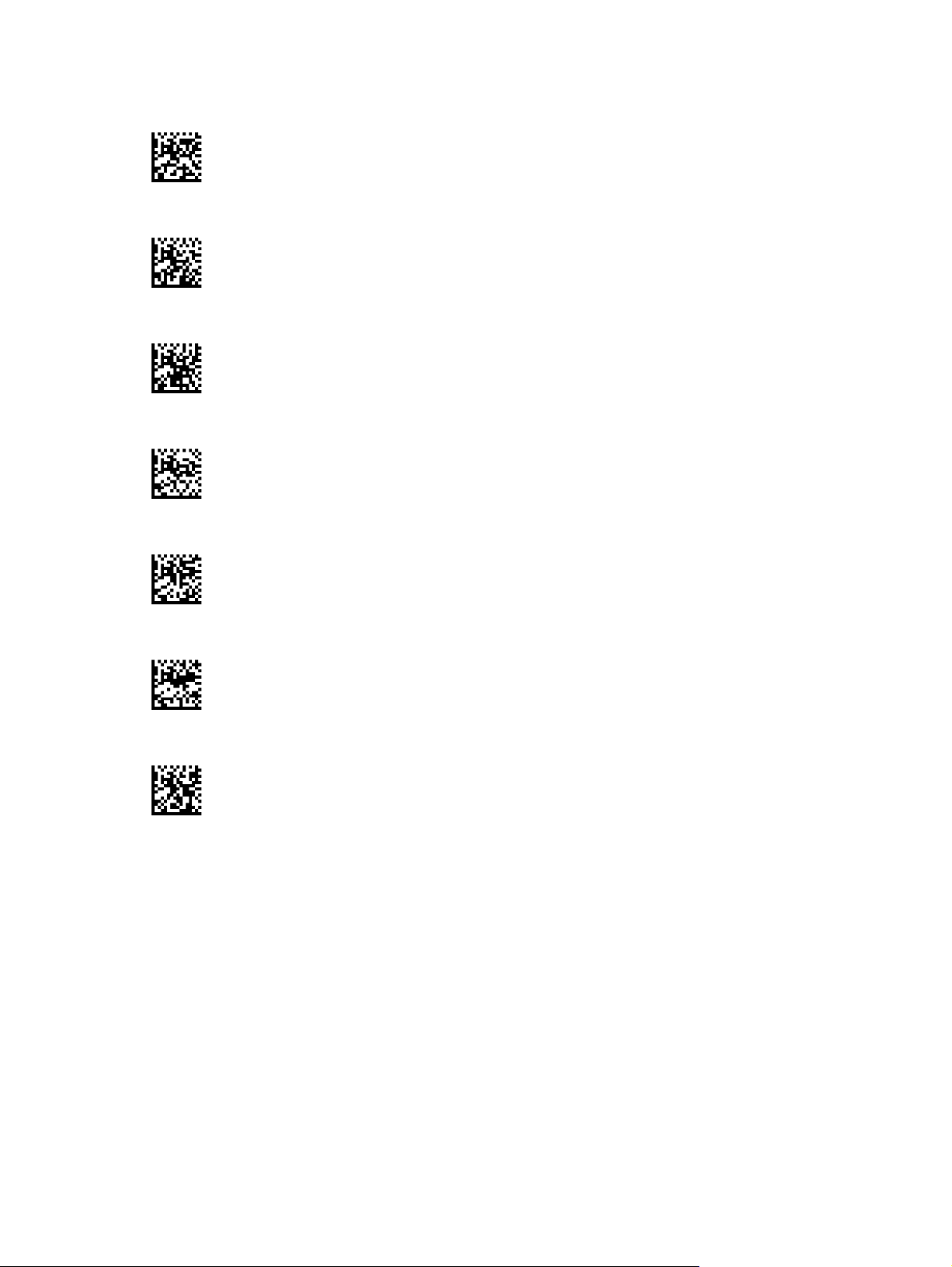
Figure 6-2 Scan Mode = Trigger Single
Figure 6-3 Scan Mode = Trigger Pulse Multiple
Figure 6-4 Scan Mode = Trigger Hold Multiple
Figure 6-5 Scan Mode = Flashing
Figure 6-6 Scan Mode = Always On
Figure 6-7 Scan Mode = Stand Mode
Figure 6-8 Pick Mode = Enabled
Multiple Label Reading
The scanner offers a number of options for multiple label reading. See the HP Wireless Barcode
Scanner Programming Reference Guide (PRG) or software configuration tool for descriptions of these
features and programming labels.
Stand Operation
This feature controls how the scanner behaves when it is placed into a cradle or stand.
Ignore Autorecognition - Disables mode switching when the scanner is placed in a stand.
●
Switch to Stand Mode - Automatically switches the scanner to Stand Mode when the scanner is
●
placed in the stand.
24 Chapter 6 Operating Modes
Page 31

Switch to Flashing - Automatically switches the scanner to Flash Mode when placed in the
●
stand.
Switch to Always On - Automatically switches the scanner to Always On mode when placed in
●
the stand.
Figure 6-9 ENTER/EXIT PROGRAMMING MODE
Figure 6-10 Ignore Autorecognition
Figure 6-11 Switch to Stand Mode
Figure 6-12 Switch to Flashing
Figure 6-13 Switch to Always On
Stand Operation 25
Page 32

A Technical Support
Online Technical Support
For the online access to technical support information, self-solve tools, online assistance, community
forums or IT experts, broad multivendor knowledge base, monitoring and diagnostic tools, go to
http://www.hp.com/support.
Preparing to Call Technical Support
If you can not solve a problem, you may need to call technical support. Have the following information
available when you call:
If the product is connected to an HP POS computer, provide the serial number of the POS
●
computer
Purchase date on invoice
●
The spares part number located on the product
●
● Condition under which the problem occurred
Error messages received
●
Hardware configuration
●
Hardware and software you are using
●
26 Appendix A Technical Support
Page 33

B Technical Specifications
The following table contains physical and performance characteristics, user environment and
regulatory information.
Item Description
Physical Characteristics
Color Black
Dimensions Height 7.1”/181 mm
Length 3.9”/100 mm
Width 2.8”/71 mm
Weight (without cable) Approximately 8.7 ounces / 246 g (reader)
Approximately 8.7 ounces / 246 g (base charger)
Electrical Characteristics
Battery Type Li-Ion battery pack
Typical charge time for full charge from full discharge
4 hours with 12V external power supply adapter
a
Max 22 hours with Host power (in this case no supply
adapter is needed)
Operating Autonomy (continuous reading) 50,000 reads (typical)
Cradle Consumption and DC Input Supply Range
Performance Characteristics
Light Source LEDs
Roll (Tilt) Angle
Pitch Angle
Skew (Yaw) Angle
Field of View Field of View
a
Charge Times are much lower when battery is within daily typical operating condition.
b
Typical input current measured under factory default configuration.
c
Based on ISO 15423 specifications.
c
c
c
Volt 4.75-14 VDC; Power <8W
bus powered mode
Up to ± 180°
± 40°
± 40°
a
b
b
; Max 500mA when in host/
27
Page 34

Depth of Field (Typical)
1
Symbology SR:
Code 39 5mil: 1.6” - 7.5” (4.0 - 19cm);
10mil: 0.4” - 11.8” (1.0 - 30cm);
20mil: up to 17.7” (up to 45cm)
EAN 7.5mil: 0.5” - 10.6” (2.0 - 27cm)
13mil: 0.6” - 15.7” (1.5 - 40cm)
PDF-417 6.6mil: 1.0” - 5.9” (2.5 - 15cm);
10mil: 0.2” - 8.6” (0.5 - 22cm);
15mil: 0.6” - 13.4” (1.5 - 34cm)
DataMatrix 10mil: 0.8” to 6.3” (2.0 - 16cm)
15mil: 0” to 9.3” (0 - 23.6cm)
QR Code 10mil: 1.2” to 4.9” (3 - 12.5cm)
15mil: 0” to 7.5” (1 - 19.0cm)
Minimum Element Width Standard Range:
1D Min. Resolution = 4 mil
PDF-417 Min.Resolution = 5 mil
Datamatrix Min. Resolution = 7 mil
Print Contrast Minimum 25% minimum reflectance
1
13 mils DOF based on EAN. All other 1D codes are Code 39. All labels grade A, typical environmental light, 20° C, label
inclination 10°.
Decode Capability
1D Bar Codes
UPC/EAN/JAN (A, E, 13, 8)
●
UPC/EAN/JAN (including P2 /P5)
●
UPC/EAN/JAN (including; ISBN /
●
Bookland & ISSN)
● UPC/EAN Coupons
Code 39 (including full ASCII)
●
Code 39 Trioptic
●
● Code39 CIP (French
Pharmaceutical)
LOGMARS (Code 39 w/ standard
●
check digit enabled)
● Danish PPT
Code 32 (Italian Pharmacode 39)
●
Code 128
●
Code 128 ISBT
●
Interleaved 2 of 5
●
Standard 2 of 5
●
Interleaved 2 of 5 CIP (HR)
●
● Industrial 2 of 5
Discrete 2 of 5
●
Datalogic 2 of 5 (China Post Code/
●
Chinese 2 of 5)
IATA 2 of 5 Air cargo code
●
Code 11
●
● Codabar
Codabar (NW7)
●
ABC Codabar
●
Code 93
●
MSI
●
PZN
●
Plessey
●
● Anker Plessey
Follet 2 of 5
●
GS1 DataBar Omnidirectional
●
● GS1 DataBar Limited
● GS1 DataBar Expanded
GS1 DataBar Truncated
●
DATABAR Expanded Coupon
●
28 Appendix B Technical Specifications
Page 35

Decode Capability
1D Bar Codes
2D / Stacked Codes
The scanner is capable of decoding the following symbologies using multiple frames (i.e. Multi-Frame Decoding):
PDF-417
●
QR Code
●
Aztec
●
Datamatrix
●
● Inverse Datamatrix
● Datamatrix is configurable for the
following parameters:
◦ Normal or Inverted
Square or Rectangular Style
◦
Data length (1 - 3600
◦
characters)
Maxicode
●
QR Codes (QR, Micro QR and
●
Multiple QR Codes)
a
It is acceptable to handle this with ULE.
Aztec
●
Sweden Post
●
Portugal Post
●
LaPoste A/R 39
●
● 4-State Canada
● Postal Codes
Australian Post
●
Japanese Post
●
KIX Post
●
Planet Code
●
Postnet
●
● Royal Mail Code (RM45CC)
Intelligent Mail Barcode (IMB)
●
Interfaces Supported USB Com Std., USB Keyboard, USB (see
on page 19 for a listing of available interface options)
PDF-417
●
MacroPDF
●
Micro PDF417
●
GS1 Composites (1 - 12)
●
● Codablock F
●
French CIP13
GS1 DataBar Stacked
●
GS1 DataBar Stacked
●
a
Omnidirectional
GS1 DataBar Expanded Stacked
●
GSI Databar Composites
●
● Chinese Sensible Code
Inverted 2D codes
●
Selecting the Interface Type
User Environment
Operating Temperature 32° to 122° F (0° to 50° C)
Storage Temperature -4° to 158° F (-20° to 70° C)
Humidity Operating: 5% to 90% relative humidity, non-condensing
Drop Specifications Scanner withstands 18 drops from 1.8 meters (5.9 feet) to
concrete
Ambient Light Immunity Up to 100,000 Lux
Contaminants Spray/rain Dust/particulates IEC 529-IP52 (scanner only)
ESD Level 16 KV
Regulatory
Complies with FDA performance standards for laser products except for deviations pursuant to Laser Notice No. 50, dated
June 24, 2007.
Radio Features
Frequency Range 2400 to 2483.5 MHz
Range (in open air) 30 m
29
Page 36

LED and Beeper Indications
The scanner’s beeper sounds and its LED illuminates to indicate various functions or errors on the
scanner. An optional “Green Spot” also performs useful functions. The following tables list these
indications. One exception to the behaviors listed in the tables is that the scanner’s functions are
programmable, and so may or may not be turned on. For example, certain indications such as the
power-up beep can be disabled using programming bar code labels.
Indicator Description LED Beeper
Power-up Beep The scanner is in the
Good Read Beep A label has been
ROM Failure There is an error in the
Limited Scanning Label
Read
Scanner Active Mode The scanner is active and
Scanner Disabled The scanner has been
Green Spot
momentarily
1
flashes
process of powering-up.
successfully scanned by the
scanner.
scanner's software/
programming.
Indicates that a host
connection is not
established.
ready to scan.
disabled by the host.
Upon successful read of a
label, the software shall turn
the green spot on for the
time specified by the
configured value.
N/A Scanner beeps four times at
LED behavior for this
indication is configurable via
the feature “Good Read:
When to Indicate” (see the
HP Wireless Barcode
Scanner Programming
Reference Guide for
information).
Flashes Scanner sounds one error
N/A Scanner 'chirps' six times at
The LED is lit steadily
The LED blinks continuously N/A
N/A N/A
1
highest frequency and
volume upon power-up.
The scanner will beep once
at current frequency, volume,
mono/bitonal setting and
duration upon a successful
label scan.
beep at highest volume.
the highest frequency and
current volume.
N/A
Image Capture When ready to capture
1
Except when in sleep mode or when a Good Read LED Duration other than 00 is selected
image.
Programming Mode - The following indications ONLY occur when the scanner is in Programming
Mode.
INDICATION DESCRIPTION LED BEEPER
Label Programming Mode
Entry
Label Programming Mode
Rejection of Label
A valid programming label
has been scanned.
A label has been rejected. N/A Scanner sounds three times
30 Appendix B Technical Specifications
Blue light flashes 2 times
when updating
LED blinks continuously Scanner sounds four low
N/A
frequency beeps.
at lowest frequency and
current volume.
Page 37

INDICATION DESCRIPTION LED BEEPER
Label Programming Mode
Acceptance of Partial Label
Label Programming Mode
Acceptance of Programming
Label Programming Mode
Cancel Item Entry
Error Codes
Upon startup, if the scanner sounds a long tone, this means the scanner has not passed its automatic
Selftest and has entered FRU (Field Replaceable Unit) isolation mode. If the scanner is reset, the
sequence will be repeated.
The following table describes the LED flashes/beep codes associated with an error found.
Number of LED Flashes/Beeps Error Corrective Action
In cases where multiple
labels must be scanned to
program one feature, this
indication acknowledges
each portion as it is
successfully scanned.
Configuration option(s) have
been successfully
programmed via labels and
the scanner has exited
Programming Mode.
Cancel label has been
scanned.
N/A Scanner sounds one short
beep at highest frequency
and current volume.
N/A Scanner sounds one high
frequency beep and 4 low
frequency beeps followed by
reset beeps.
N/A Scanner sounds two times at
low frequency and current
volume.
1 Configuration Contact Help desk for assistance
2 Interface PCB Contact Help desk for assistance
6 Digital PCB Contact Help desk for assistance
12 Imager Contact Help desk for assistance
15 Accelerometer Contact Help desk for assistance
Error Codes 31
Page 38

C Agency Regulatory Notices
In some environments, the use of wireless devices may be restricted. Such restrictions may apply onboard airplanes, in hospitals, near explosives, in hazardous locations, and so on. If you are uncertain
of the policy that applies to the use of this product, ask for authorization to use it before you turn it on.
Federal Communications Commission Notice
This equipment has been tested and found to comply with the limits for a Class B digital device,
pursuant to Part 15 of the FCC Rules. These limits are designed to provide reasonable protection
against harmful interference in a residential installation. This equipment generates, uses, and can
radiate radio frequency energy and, if not installed and used in accordance with the instructions, may
cause harmful interference to radio communications. However, there is no guarantee that interference
will not occur in a particular installation. If this equipment does cause harmful interference to radio or
television reception, which can be determined by turning the equipment off and on, the user is
encouraged to try to correct the interference by one or more of the following measures:
Reorient or relocate the receiving antenna.
●
Increase the separation between the equipment and the receiver.
●
● Connect the equipment into an outlet on a circuit different from that to which the receiver is
connected.
Consult the dealer or an experienced radio or television technician for help.
●
Modifications
The FCC requires the user to be notified that any changes or modifications made to this device that
are not expressly approved by Hewlett Packard Company may void the user's authority to operate the
equipment.
Cables
Connections to this device must be made with shielded cables with metallic RFI/EMI connector hoods
to maintain compliance with FCC Rules and Regulations.
Declaration of Conformity for Products Marked with the FCC Logo (United States Only)
This device complies with Part 15 of the FCC Rules. Operation is subject to the following two
conditions:
1. This device may not cause harmful interference.
2. This device must accept any interference received, including interference that may cause
undesired operation.
For questions regarding the product, contact:
Hewlett Packard Company
P. O. Box 692000, Mail Stop 530113
32 Appendix C Agency Regulatory Notices
Page 39

Houston, Texas 77269-2000
Or, call 1-800-HP-INVENT (1-800 474-6836)
For questions regarding this FCC declaration, contact:
Hewlett Packard Company
P. O. Box 692000, Mail Stop 510101
Houston, Texas 77269-2000
Or, call (281) 514-3333
To identify this product, refer to the Part, Series, or Model number found on the product.
Canadian Notice
This Class B digital apparatus meets all requirements of the Canadian Interference-Causing
Equipment Regulations. CAN ICES-3(B)/NMB-3(B).
If this device has WLAN or Bluetooth capability, the device complies with Industry Canada licenceexempt RSS standard(s). Operation is subject to the following two conditions: (1) this device may not
cause interference, and (2) this device must accept any interference, including interference that may
cause undesired operation of the device.
Avis Canadien
Cet appareil numérique de la classe B respecte toutes les exigences du Règlement sur le matériel
brouilleur du Canada. CAN ICES-3(B)/NMB-3(B).
Canadian Notice 33
Page 40

European Union Regulatory Notice
Products bearing the CE marking comply with one or more of the following EU Directives as may be
applicable:
Low Voltage Directive 2006/95/EC; EMC Directive 2004/108/EC; Ecodesign Directive 2009/125/EC;
R&TTE Directive 1999/5/EC; RoHS Directive 2011/65/EU
Compliance with these directives is assessed using applicable European Harmonised Standards.
The full Declaration of Conformity can be found at the following web site:
(Search with the product model name or its Regulatory Model Number (RMN), which may be found
on the regulatory label.)
The point of contact for regulatory matters is: Hewlett-Packard GmbH, Dept./MS: HQ-TRE,
Herrenberger Strasse 140, 71034 Boeblingen, GERMANY.
Mexico Notice
Declaración para México
La operación de este equipo está sujeta a las siguientes dos condiciones: (1) es posible que este
equipo o dispositivo no cause interferencia perjudicial y (2) este equipo o dispositivo debe aceptar
cualquier interferencia, incluyendo la que pueda causar su operación no deseada.
Radio Model: DLBTMCX
Frequency: 2400 to 2483.5 MHz
Laser Compliance
This device is classified as a Class 2 Laser Product in accordance with US FDA regulations and the
IEC 60825-1.
Each laser product complies with 21 CFR 1040.10 and 1040.11 except for deviations pursuant to
Laser Notice No. 50, dated June 24, 2007; and with IEC 60825-1:2007
http://www.hp.eu/certificates
CAUTION: CLASS 2 LASER RADIATION DO NOT STARE INTO THE BEAM
Output Radiation 1mW Avg. Emitted Wave Length 650nm
WARNING! Use of controls or adjustments or performance of procedures other than those specified
herein or in the laser product's installation guide may result in hazardous radiation exposure. To
reduce the risk of exposure to hazardous radiation:
• Do not try to open the module enclosure. There are no user-serviceable components inside.
• Do not operate controls, make adjustments, or perform procedures to the laser device other than
those specified herein.
• Allow only HP Authorized Service technicians to repair the unit.
34 Appendix C Agency Regulatory Notices
Page 41

Product Environmental Notices
Materials Disposal
Some HP LCD monitors contain mercury in the fluorescent lamps that might require special handling
at end-of-life.
Disposal of this material can be regulated because of environmental considerations. For disposal or
recycling information, contact the local authorities or the Electronic Industries Alliance (EIA)
http://www.eiae.org.
Disposal of Waste Equipment by Users in Private Household in the European Union
This symbol on the product or on its packaging indicates that this product must not be disposed of
with your household waste. Instead, it is your responsibility to dispose of your waste equipment by
handing it over to a designated collection point for the recycling or waste electrical and electronic
equipment. The separate collection and recycling of your waste equipment at the time of disposal will
help to conserve natural resources and ensure that it is recycled in a manner that protects human
health and the environment. For more information about where you can drop off your waste
equipment for recycling, please contact the local city office, the household waste disposal service or
the shop where you purchased the product.
HP Recycling Program
HP encourages customers to recycle used electronic hardware, HP original print cartridges, and
rechargeable batteries. For more information about recycling programs, go to
recycle.
Chemical Substances
HP is committed to providing our customers with information about the chemical substances in our
products as needed to comply with legal requirements such as REACH (Regulation EC No
1907/2006 of the European Parliament and Council). A chemical information report for this product
can be found at
http://www.hp.com/go/reach.
http://www.hp.com/
Product Environmental Notices 35
 Loading...