

Page 1

About this Manual
We’ve added this manual to the Agilent website in an effort to help you support
your product. This manual is the best copy we could find; it may be incomplete
or contain dated information. If we find a more recent copy in the future, we will
add it to the Agilent website.
Support for Your Product
Agilent no longer sells or supports this product. Our service centers may be able
to perform calibration if no repair parts are needed, but no other support from
Agilent is available. You will find any other available product information on the
Agilent Test & Measurement website, www.tm.agilent.com.
HP References in this Manual
This manual may contain references to HP or Hewlett-Packard. Please note that
Hewlett-Packard's former test and measurement, semiconductor products and
chemical analysis businesses are now part of Agilent Technologies. We have
made no changes to this manual copy. In other documentation, to reduce
potential confusion, the only change to product numbers and names has been in
the company name prefix: where a product number/name was HP XXXX the
current name/number is now Agilent XXXX. For example, model number
HP8648A is now model number Agilent 8648A.
Page 2

User's Guide
HP
Spectrum
HP
Source-Controlled Modules
70000
70900B
Series
Analyzer
Local
Modular
Oscillator
System
ABCDE
HP Part No. 70900-90286
Printed in USA March 1994
Edition A.0.0
Page 3

Notice
The information contained in this document is subject to change without notice.
Hewlett-Packard makes no warranty of any kind with regard to this material, including,
but not limited to, the implied warranties of merchantability and tness for a particular
purpose. Hewlett-Packard shall not be liable for errors contained herein or for incidental or
consequential damages in connection with the furnishing, performance, or use of this material.
Restricted Rights Legend.
Use, duplication, or disclosure by the U.S. Government is subject to restrictions as set forth
in subparagraph (c) (1) (ii) of the Rights in Technical Data and Computer Software clause at
DFARS 252.227-7013 for DOD agencies, and subparagraphs (c) (1) and (c) (2) of the Commercial
Computer Software Restricted Rights clause at FAR 52.227-19 for other agencies.
c
Copyright Hewlett-Packard Company 1990, 1991, 1992, 1994
All Rights Reserved. Reproduction, adaptation, or translation without prior written permission
is prohibited, except as allowed under the copyright laws.
1400 Fountaingrove Parkway, Santa Rosa, CA 95403-1799, USA
Page 4

Certication
Hewlett-P
time
measurements
T
echnology
facilities
Warranty
This
workmanship
Hewlett-Packard Company will, at its option, either repair or replace products which prove to
be defective.
For warranty service or repair, this product must be returned to a service facility designated by
Hewlett-Packard. Buyer shall prepay shipping charges to Hewlett-Packard and Hewlett-Packard
shall
shipping
country
Hewlett-P
use
that
software, or rmware will be uninterrupted or error-free.
ackard
of
shipment
,
to
of
other
Hewlett-P
pay
shipping
charges
.
ackard
with
an
instrument will execute its programming instructions when properly installed on
instrument.
Company
from
are
traceable
the
extent
International
ackard
for
a
period
charges
,
duties
warrants
Hewlett-P
certies
the
factory
to
allowed
instrument
of one year from date of shipment. During the warranty period,
to
, and taxes for products returned to Hewlett-Packard from another
that its software and rmware designated by Hewlett-Packard for
ackard does not warrant that the operation of the instrument, or
that
this
product
.
Hewlett-P
the
United
by
the Institute's calibration facility, and to the calibration
Standards Organization members.
product is warranted against defects in material and
return
the
ackard further certies that its calibration
States
product
met
National
to
Buyer
its published specications at the
Institute of Standards and
.
However
, Buyer shall pay all
Limitation of Warranty
The foregoing warranty shall not apply to defects resulting from improper or inadequate
maintenance by Buyer, Buyer-supplied software or interfacing, unauthorized modication or
misuse, operation outside of the environmental specications for the product, or improper
site
preparation
NO OTHER WARRANTY IS EXPRESSED OR IMPLIED. HEWLETT-PACKARD SPECIFICALLY
DISCLAIMS THE IMPLIED WARRANTIES OF MERCHANTABILITY AND FITNESS FOR A
PARTICULAR PURPOSE.
Ex
clusive Remedies
THE
REMEDIES PROVIDED HEREIN ARE BUYER'S SOLE AND EXCLUSIVE REMEDIES.
HEWLETT-PACKARD SHALL NOT BE LIABLE FOR ANY DIRECT, INDIRECT, SPECIAL,
INCIDENTAL, OR CONSEQUENTIAL D
OR ANY OTHER LEGAL THEORY
Assistance
Product maintenance agreements and other customer assistance agreements are available for
Hewlett-Packard products.
For any assistance, contact your nearest Hewlett-Packard Sales and Service Oce.
or
maintenance
.
AMAGES, WHETHER B
.
ASED ON CONTRA
CT,
TORT,
iii
Page 5

Safety
The
of
the
CA
UTION
WARNING
DANGER
Symbols
following
symbols
safety
symbols
and
its
meaning
The
CAUTION
not correctly performed or adhered to, could result in damage to or destruction
of the product or the user's work. Do not proceed beyond a
until the indicated conditions are fully understood and met.
The
W
ARNING
which,
to
the
user
conditions
The
DANGER
reader of a procedure which, if not correctly performed or adhered to,
could
sign
result
until
are
used
throughout
before
sign denotes a hazard. It calls attention to a procedure which, if
sign
if
not
correctly
.
Do
are
fully
sign denotes an imminent hazard to people. It warns the
in injury or loss of life. Do not proceed beyond a
the indicated conditions are fully understood and met.
denotes
not
proceed
understood
operating
performed
this
manual. Familiarize yourself with each
this instrument.
a
hazard.
beyond
or
and
It
adhered
a
WARNING
met.
CAUTION
calls attention to a procedure
to
, could result in injury
sign until the indicated
sign
DANGER
iv
Page 6

General
Safety
Considerations
WARNING
CA
UTION
Before
grounded
socket
Any
or
terminal
There
personal injury. Be extremely careful.
Any adjustments or service procedures that require operation of the
instrument with protective covers removed should be performed only by
trained service personnel.
Before this instrument is switched on, make sure its primary power circuitry
has been adapted to the voltage of the ac power source.
F
ailure
the
this
through
outlet
interruption
outside
can
are
to
set
instrument
instrument
provided
the
instrument, or disconnection of the protective earth
result
many
points in the instrument which can, if contacted, cause
the
ac
power
when
is switched on, make sure it has been properly
the
protective
with
of
the protective (grounding) conductor, inside
in personal injury.
input
the
ac
power
conductor
protective
to
the correct voltage could cause damage to
cable
is
of
earth
plugged
the
ac power cable to a
contact.
in.
v
Page 7
In
This
This
manual
lightwave
Book
explains
signal
how
analyzers
to
.
operate
HP
70000
Series modular spectrum analyzer systems and
Spectrum
in the following chapters.
Chapter
analyzer
rst
Chapter
4
MENU
Chapter 3 provides a set of quick reference tables that list all softkeys by functional group.
The softkeys are listed alphabetically within each functional group.
Chapter 4 provides detailed descriptions of each softkey. The softkey descriptions are
organized alphabetically.
Troubleshooting
Chapter
Chapter
Refer to the appendixes and glossary for the following information:
Appendix A describes spectrum analyzer and lightwave-signal-analyzer theory of
operation. The appendix also provides individual block diagrams for HP 70000 Series
modular spectrum analyzer system modules.
Appendix B describes inputs and outputs on individual HP 70000 Series modular spectrum
analyzer
Appendix
lightwave
Appendix
sequences
Glossary denes spectrum analyzer, lightwave-signal-analyzer, and modular-measurement
system terminology.
analyzer
1
describes
.
The
time
.
2
illustrates
5
softkey.
5
provides modular system troubleshooting procedures.
6
provides descriptions for displayed system error messages.
system
C
signal
D
.
and
lightwave
the
basic operation of a spectrum analyzer and lightwave signal
chapter
information is provided in the following chapters.
describes
provides
also provides details for an analyzer that is being operated for the
the organization of the softkeys that are accessed by pressing the
modules
analyzers
.
how
reference
.
A
to
signal
brief
care
tables
analyzer
description
for
ber-optic
for
ASCII
features
of
each
connectors
characters
module is also provided.
and
operating details are provided
and cables that are used with
, control codes, and escape
vi
Page 8

Contents
1. Overview
Notation Conventions Used in this Manual . . . . . . . . . . . . . . . . . . . 1-1
Front-Panel Controls . . . . . . . . . . . . . . . . . . . . . . . . . . . . . 1-2
Analyzer Functions ...... ...... ...... ..... ..... 1-2
Active Function and Data Entry .. ...... ...... ...... .. 1-2
Front-Panel Controls . . . . . . . . . . . . . . . . . . . . . . . . . . . . 1-3
Accessing Analyzer Functions with the Instrument Keypad . . . . . . . . . . . 1-5
Accessing Analyzer Functions with the
Preparing the Analyzer for Measurements . . . . . . . . . . . . . . . . . . . 1-7
Electrical Cable Connections ..... ..... ...... ...... ... 1-10
Fiber-Optic
Cleaning
Making
Instrument
Measurement
Use
Resolving
Viewing Low-Level Signals . . . . . . . . . . . . . . . . . . . . . . . . . 1-13
Interpreting Measurement Results ...... ...... ...... .... 1-14
Common Measurement Indicators . . . . . . . . . . . . . . . . . . . . . . 1-14
Lightwave Signal Analyzer Measurement Indicators ...... ...... . 1-17
Auxiliary Measurement Indicators . . . . . . . . . . . . . . . . . . . . . . 1-19
Interpreting
Using
Presetting the User Softkeys .... ...... ...... ...... .. 1-23
Creating a Custom Menu of User Softkeys . . . . . . . . . . . . . . . . . . 1-23
Incorporating User-Dened Functions into the User-Softkey Menu .. .... 1-25
Restricting Instrument Operation to User Softkeys . . . . . . . . . . . . . . 1-25
Using the
Accessing Custom, User-Dened Functions .................. 1-28
Accessing the Memory Card .... ...... ..... ...... .... 1-29
Formatting a Memory Card . . . . . . . . . . . . . . . . . . . . . . . . .
Cable
Optical
a
Measurement
Preset
Coupled
Closely
Front-P
the
4
USER
4
DISPLAY
Connections
Connectors
...... ...... ...... ...... .... 1-11
............................. 1-11
Procedure
Functions to Maintain Accuracy Easily .......... ... 1-12
Spaced Signals ...................... 1-13
anel
Indicators
5
Key
.
.
5
Key ........ ...... ...... ...... . 1-26
.
...... ...... ...... ...... 1-10
...... ...... ...... ..... ... 1-11
.
.
.
.
4
5
MENU
.
.
.
.
.
.
...................... 1-23
Key............... 1-6
.
.
.
.
................ 1-10
.
.
.
................. 1-21
1-30
2. Softkey Menu Maps
NNNNNNNNNNNNNN
Freq
NNNNNNNNNNNNNNNNN
NNNNNNNNNNNNNNNNNNNN
NNNNNNNNNNNNNNNNNNNN
NNNNNNNNNNNNNNNNNNNN
NNNNNNNNNNNNNNNNN
NNNNNNNNNNNNNN
Softkey Menu . . . . . . . . . . . . . . . . . . . . . . . . . . . . .
Amptd
Marker
BW,Swp
Traces
State
Misc
Softkey Menu .... ...... ..... ...... ...... . 2-3
Softkey Menu . . . . . . . . . . . . . . . . . . . . . . . . . . . .
Softkey Menu . . . . . . . . . . . . . . . . . . . . . . . . . . . . 2-5
Softkey Menu . . . . . . . . . . . . . . . . . . . . . . . . . . . . 2-6
Softkey Menu .... ...... ..... ...... ...... . 2-7
Softkey Menu . . . . . . . . . . . . . . . . . . . . . . . . . . . . . 2-12
2-2
2-4
Contents-1
Page 9

3. SoftKey Quick Reference
Functional Grouping Denitions ........ ...... ...... ... 3-22
4. Softkey Descriptions
NNNNNNNNNN
N
1/T
NNNNNNNNNNNNNNNNNNNNNNNNNNNNNNNNNNNNNNNNNNN
N
3-DIMEN On Off
NNNNNNNNNNNNNNNNNNNNNNNNNNNNNNNNNNNNNNNNNNNN
66 MODE On Off
N
N
A<-A+B
N
N
A-B->A
N
N
A-B+DL
NNNNNNNNNNNNNNNNNNNNNNNNNNNNNNNNNNNNNNNNNNNN
A-C ->A On Off
NNNNNNNNNNNNNNNNNNNNNNNNNNNNNNNNNNNNNNNNN
ACTIVE MARKER
NNNNNNNNNNNNNNNNNNNNNNN
ALC ALT
NNNNNNNNNNNNNNNNNNNNNNN
ALC EXT
NNNNNNNNNNNNNNNNNNNNNNN
ALC NRM
NNNNNNNNNNNNNNNNNNNNNNNNNNNNN
alc/track
N
NNNNNNNNNNNNNNNNNNNNNNNNNNNNNNNNNNNN
A6A*DL/(A+B)
NNNNNNNNNNNNNNNNNNNNNNNNNNNNNNNNNNNNNNNNNNN
A6A*DL/(A+B+C)
N
N
A
N
N
A
N
NNNNNNNNNNNNNNNN
A6A0B
NNNNNNNNNNNNNNNNNNNNNNNNNN
A6A0B+DL
N
N
A
N
N
A
NNNNNNNNNNNNNNNNN
A6A0C
NNNNNNNNNNNNNNNNNNNNNNNNNN
A6A0C+DL
NNNNNNNNNNNNNNNNNNNNNNNNNNNNNNNNNNNNNNNN
A6DL*(A+B)/C)
N
N
A
NNNNNNNNNNNNNNNNNNNNNNN
AM FREQ
NNNNNNNNNNNNNNNNNNNNNNNNNNNNNNNN
AM INT EXT
NNNNNNNNNNNNNNNNNNNNNNNNNNNNNNNNNNN
AM % On Off
NNNNNNNNNNNNNNNNNNNNNNNNNNNNNNNNNNNNNNNNNNNNNNN
AMPCOR -> LOWER
NNNNNNNNNNNNNNNNNNNNNNNNNNNNNNNNNNNNNNNNN
AMPCOR On Off
NNNNNNNNNNNNNNNNNNNNNNNNNNNNNNNNNNNNNNNNNNNNNNN
AMPCOR -> UPPER
NNNNNNNNNNNNNNNNNNNNNNNNNNNNNNNNNNNNNNNNNNNN
AMP REF OFFSET
NNNNNNNNNNNNNNNNNNNNNNNNNNNNNNNNNNN
AMPTD VALUE
NNNNNNNNNNNNNNNNNNNNNNNNNNNNNNNNNNNNNN
ANALYZR TEST
NNNNNNNNNNNNNNNNNNNNNNNNNNNNNNNNNNNNNNNNNNNN
ANOTATN On Off
NNNNNNNNNNNNNNNNNNNNNNN
ANY CHR
NNNNNNNNNNNNNNNNNNNNNNNNNNNNNNNNNNNNNNNNN
ATTEN AutoMan
NNNNNNNNNNNNNNNNNNNNNNNNNNNNNNNNNNNNNNNNNNNNNNN
A UNITS AutoMan
.................................... 4-1
.............................. 4-1
N
N
N
N
N
N
N
N
NNNNNNNNNN
.
N
N
N
N
N
NNNNNNNNNNNNNNNNNNNNNNNNNNNNNNNNNN
N
NNNNNNNNNNNNNNNNNNNNNNNNNNNNNNNNNNNNNN
N
N
N
N
N
N
N
N
N
N
6
A*DL/B)
N
N
N
N
N
NNNNNNNNNNNNNNNNNNNNN
6
A*DL/C)
N
N
N
N
N
N
N
N
N
N
6
(A
N
N
N
N
N
NNNNNNNNNNNNNNNNNNNNNNNNNNNNNNNN
6
(A
N
N
N
N
N
NNNNNNNNNNNNNNNNNN
METER
.
On
Off
On Off
.................................. 4-5
.................................. 4-5
.................................. 4-6
N
NNNNNNNNNNNNNNN
...... ...... ...... ...... ...... ..... 4-9
N
NNNNNNNNNNNNNNNNN
0
B)
0
C
0B)0
C+DL
...... ...... ...... ...... ...... ..... 4-11
N
N
N
N
N
N
NNNNNNNNNNNNN
On Off
.................................. 4-13
.................................. 4-18
.............................. 4-2
.
.
.
.
.
............................ 4-2
.
.
...... ...... ...... ...... ..... 4-3
...... ...... ...... ...... ...... . 4-3
.............................. 4-4
...... ...... ...... ...... ...... . 4-4
.
.
...... ...... ...... ...... ...... . 4-6
...... ...... ...... ...... ...... . 4-7
.............................. 4-7
.
.
.
.
.
.
...... ...... ...... ...... ... 4-8
...... ...... ...... ...... ...... ... 4-8
...... ...... ...... ...... ...... ... 4-9
.
.
...... ...... ...... ...... ...... . 4-10
...... ...... ...... ...... ...... . 4-10
...... ...... ...... ...... ...... ... 4-11
...... ...... ...... ...... ...... . 4-12
.............................. 4-12
................................ 4-13
................................ 4-14
...... ...... ...... ...... ..... 4-14
...... ...... ...... ...... ...... .
...... ...... ...... ...... ..... 4-15
..............................
................................ 4-17
...... ...... ...... ...... ...... . 4-17
.............................. 4-18
...... ...... ...... ...... ...... . 4-19
...... ...... ...... ...... ..... 4-20
4-15
4-16
Contents-2
Page 10

NNNNNNNNNNNNNNNNNNNNNNNNNNNNNNNNNNNNNNNNNNNN
AUTZERO On Off
NNNNNNNNNNNNNNNNNNNNNNNNNNNNNNNNNNNNNNNNNNNNNNN
AVERAGE SHRT->C
N
N
N
N
N
N
N
N
NNNNNNNNNNNNNNN
A
XCH
B
.
.
N
N
N
N
N
NNNNNNNNNNNNNNNNNN
A
XCH
N
N
NNNNNNNNNNNNNNNNNNNNN
B<-B-DL
NNNNNNNNNNNNNNNNNNNNNNNNNNNNNNNNNNNNNNNNN
BEEPER On Off
NNNNNNNNNNNNN
N
bias
NNNNNNNNNNNNNNNNNNNNNNNNNNNNNNNNNN
N
BIAS ADJUST
NNNNNNNNNNNNNNNNNNNNNNNNNNNNNNNNNN
N
BIAS
N
N
N
N
BIAS
N
N
N
N
BIAS
N
NNNNNNNNNNNNNNNNNNNNNNNNNNNNNNNNN
N
BIAS PK RES
NNNNNNNNNNNNNNNNNNNNNNNNNNNNNNNNNNNNNNNNN
BIAS PK START
NNNNNNNNNNNNNNNNNNNNNNNNNNNNNNNNNNNNNNNNNNNN
BLANKNG On Off
NNNNNNNNNNNNNNNNNNNNNNNNNNNNNNNNNNNNNN
BLANK TRACES
N
N
N
N
BLOB
N
N
N
N
BNKSTRT
N
N
NNNNNNNNNNNNNNNNNNNNN
BXCHC
NNNNNNNNNNNNNNNNNNNNNNN
CAL ALL
N
N
N
N
cal
N
N
N
N
CAL
N
N
NNNNNNNNNNNNNNNNNNNNNNNNNNNNNN
CAL LOGAMP
NNNNNNNNNNNNNNNNNNNNNNNNNN
cal menu
NNNNNNNNNNNNNNNNNNNNNNNNNNNNNNNN
CAL
N
N
N
N
CAL
N
N
NNNNNNNNNNNNNNNNNNNNNNNNNNNNNNNNNNNNNNNNNN
cal src values
NNNNNNNNNNNNNNNNNNNNNNNNNNNNNNNN
CAL VID BW
NNNNNNNNNNNNNNNNNNNN
CANCEL
NNNNNNNNNNNNNNNNNNNNNNNNNNNNNNNNNNNNNNNNN
catalog & MSI
NNNNNNNNNNNNNN
C<-B
NNNNNNNNNNNNNNNNNNNN
CENTER
NNNNNNNNNNNNNNNNNNNNNNNNNNNNNNNNNNNNNN
CENTER DELTA
NNNNNNNNNNNNNNNNN
-> CF
NNNNNNNNNNNNNNNNNNNNNNNNNNNNNNNN
-> CF STEP
NNNNNNNNNNNNNNNNNNNNNNNNNNNNNNNNNNNNNNNNNNNNNNN
CF STEP AutoMan
NNNNNNNNNNNNNNNNNNNNNNNNNNNNNNNNNNNNNNNNN
CHANGE PREFIX
NNNNNNNNNNNNNNNNNNNNNNNNNNNNNNNNNNNNNN
CLEAR TO END
NNNNNNNNNNNNNNNNNNNNNNNNNNNNNNNNNNN
CLEAR WRT A
NNNNNNNNNNNNNNNNNNNNNNNNNNNNNNNNNNN
CLEAR WRT B
NNNNNNNNNNNNNNNNNNNNNNNNNNNNNNNNNNN
CLEAR WRT C
C
.................................... 4-24
On
N
N
N
N
NNNNNNNNNNNNNNNNNNNNNNNNNNN
PK
N
NNNNNNNNNNNNNNNNNNNNNNNNNNNNNN
PK
N
N
N
N
N
N
N
N
N
N
N
NNNNNNNNNNNNNNNNNNNN
On
N
N
N
N
N
NNNNNNNNNNNNNNNNNNNNNNNNNNNNNNNNNNN
N
N
N
N
N
N
N
N
N
N
N
NNNNNNNNNNNNNNNNN
enable
N
N
N
N
NNNNNNNNNNNNNNNNNN
GAIN
RES
N
N
N
N
N
N
N
N
N
N
NNNNNNNNNNNNNNNNNNNNNNNNNNNN
N
NNNN
SRC
...... .
.
.................................. 4-23
.................................. 4-23
................................ 4-25
Off
.
MAX
.
MIN
................................ 4-26
................................ 4-26
Off
.
On
Off
.................................. 4-29
.................................. 4-30
.
.
.
................................ 4-31
..... ...... ..... ...... ...... ..... 4-31
BW
.
INT
EXT
................................ 4-33
..... ...... ..... ...... ...... ...... . 4-33
..... ...... ..... ...... ...... ...... . 4-36
..... ...... ..... ...... ...... ...... . 4-37
................................
................................ 4-39
................................ 4-40
................................ 4-40
.............................. 4-20
..... ..... ...... ...... ...... . 4-21
..... ..... ...... ...... ...... ... 4-22
..... ..... ...... ...... ...... ... 4-24
.
.
.
.
..... ..... ...... ...... ..... 4-25
.
.............................. 4-25
..... ..... ...... ...... ...... ... 4-27
.............................. 4-27
..... ..... ...... ...... ...... ... 4-28
.
.
.
.
.
.
.
........................ 4-28
.
..... ..... ...... ...... ...... . 4-28
.
.
.
.
.
.
.
........................ 4-30
..... ..... ...... ...... ...... ... 4-31
.
.
.
.
.
.
.... ...... ...... ...... ... 4-32
..... ..... ...... ...... ...... . 4-32
.............................. 4-33
..... ..... ...... ...... ...... ... 4-34
..... ..... ...... ...... ...... . 4-36
..... ..... ...... ...... ...... ...
..... ..... ...... ...... ...... . 4-38
..... ..... ...... ...... ...... ... 4-38
..... ..... ...... ...... ...... ... 4-39
4-36
4-37
Contents-3
Page 11

NNNNNNNNNNNNNNNNNNNNNNNNNNNNNNNNNNNNNNNNNNN
C6DAC SEARCH
NNNNNNNNNNNNNNNNNNNNNNNNNNNNN
CLOSE PIT
N
N
N
N
N
N
N
N
NNNNNNNNNNNNNNNNNNNNNNNNNNNNNN
CLOSEST
N
N
N
N
N
NNNNNNNNNNNNNNNNNN
COMMAND
N
N
NNNNNNNNNNNNNNNNNN
CONFIG
NNNNNNNNNNNNNNNNNNNNNNNNNNNNNNNNNNNNNNNNNNNN
CONFIRM DELETE
NNNNNNNNNNNNNNNNNNNNNNNNNNNNNNNNNNNNNNNN
N
CONFIRM ERASE
NNNNNNNNNNNNNNNNNNNNNNNNNNNNNNNNNNNNNNNNNNNNNN
N
CONFIRM RESTART
NNNNNNNNNNNNN
N
CONT
N
N
CONT
N
N
CONV
N
N
COUPLNG AC DC
NNNNNNNNNNNNNNNNNNNNNNNNNNNNNNNNNNNNNNNNNNNN
CPL AVG On Off
NNNNNNNNNNNNNNNNNNNNNNNNNNNNNNNNNNNNNNNNNNNN
CPL DET On Off
NNNNNNNNNNN
dBm
N
N
dB
N
N
dBmV
N
N
debug
NNNNNNNNNNNNNNNNNNNNNNNNNNNNNNNN
DEBUG FAST
N
N
DEBUG
N
N
DEBUG
N
N
DEFINE USR KEY
NNNNNNNNNNNNNNNNNNNNNNNNNNNNNNNN
DELETE ALL
NNNNNNNNNNNNNNNNNNNNNNNNNNNNNNNNNNN
DELETE
N
N
DELETE
N
N
DELETE SEGMENT
NNNNNNNNNNNNNNNNN
DELTA
NNNNNNNNNNNNNNNNNNNNNNN
detectr
NNNNNNNNNNNNNNNNNNNNNNNNNNNNNNNNNNNNNNNNNNNNNNN
DETECTR AutoMan
NNNNNNNNNNNNNNNNNNNNNNNNNNNNNNNNNNNNNNNNNNNNNNN
DETECTR GND AUT
NNNNNNNNNNNNNNNNNNNNNNNNNNNNNNNNNNNNNNNNN
DET SEL LOG V
NNNNNNNNNNNNNNNNNNNNNNNNNNNNNNNNNNNNNN
DISPOSE USER
NNNNNNNNNNNNNNNNNNNNNNNNNNNNNNNNNNNNNNNNNNNN
DSP LIN On Off
NNNNNNNNNNNNNNNNNNNNNNNNNNNNNNNNNNNNNN
EDIT FUNCDEF
NNNNNNNNNNNNNNNNNNNNNNNNNNNNNNNN
edit limit
NNNNNNNNNNNNNNNNNNNNNNNNNNNNNNNNNNNNNNNNN
ENTER COMMAND
NNNNNNNNNNNNNNNNNNNNNNNNNNNNNNNNNNN
enter limit
NNNNNNNNNNNNNNNNNNNNNNNNNNNNNNNN
ENTER LINE
NNNNNNNNNNNNNNNNNNNNNNNNNNNNN
ERASE ALL
NNNNNNNNNNNNNNNNNNNNNNNNNNNNNNNNNNNNNNNNN
erase/restart
.
N
N
N
N
N
N
NNNNNNNNNNNNNNNNNNNNNNNN
SWEEP
N
N
N
NNNNNNNNNNNNNNNNNNNNNNNN
LOSS
NNNNNNNNNNNNNNNNNNNNNNNNNNNNNNNNNNNNNNN
.................................... 4-49
N
N
N
N
N
N
N
N
N
N
N
N
V
.
N
N
N
N
N
N
N
NNNNN
.
NNNNNNNNNNNNNNN
N
N
N
N
N
N
N
N
N
N
N
N
N
NNNNNNNNNNNNNNNNNNNNNNN
N
N
N
N
N
N
NNNNNNNNNNNNNNNNNNNNNNNN
NNNNNNNNNNNNNNNNNNNNNNNNNNNNNNNNNNNNNNNNNN
N
N
N
N
N
N
NNNNNNNNNNNNNNNNNNNNNNNNNNNNNN
NNNNNNNNNNNNNNNNNNNNNNNNNNNNNNNNNNNNNNNNNN
...... ...... ...... ...... ...... ... 4-41
PEAK
.
.
................................ 4-42
...... ...... ...... ...... ...... ..... 4-44
.
.
.
.
.
...... ...... ...... ...... ...... ... 4-47
.
.
.
.
.
.
...... ...... ...... ...... ...... ... 4-50
...... ...... ...... ...... ...... ..... 4-50
................................ 4-50
On
Off
SLOW
CHAR
or...
.
................................ 4-53
.
...... ...... ...... ...... ...... ..... 4-55
.................................. 4-55
................................ 4-59
................................ 4-60
................................ 4-60
...... ...... ...... ...... ...... ... 4-61
.............................. 4-41
.
.
.
.
...... ...... ...... ...... ... 4-42
.............................. 4-45
...... ...... ...... ...... ...... . 4-45
...... ...... ...... ...... ..... 4-45
.
.
...... ...... ...... ...... ..... 4-46
.
.
...... ...... ...... ...... ..... 4-46
...... ...... ...... ...... ...... . 4-47
.............................. 4-48
.............................. 4-48
.
.
.
............................ 4-49
.
.
.
.
.
.
.
........................ 4-51
.
.............................. 4-52
.............................. 4-52
.
.
.
.
.
.
.
........................ 4-53
.
.
...... ...... ...... ...... ..... 4-54
.............................. 4-54
...... ...... ...... ...... ..... 4-56
.....
...... ...... ...... ...... ...... . 4-57
...... ...... ...... ...... ...... .
.............................. 4-58
...... ...... ...... ...... ...... .
...... ...... ...... ...... ...... . 4-59
...... ...... ...... ...... ...... . 4-61
........................ 4-56
4-57
4-58
Contents-4
Page 12

NNNNNNNNNNNNNNNNNNNNNNNNNNNNNNNNNNN
execute DLP
NNNNNNNNNNN
EXT
N
N
EXTEND
N
N
EXT
N
N
ext mixer
NNNNNNNNNNNNNNNNNNNNNNNNNNNNNNNNNNNNNNNNN
EXT VID FM IQ
NNNNNNNNNNNNNNNNNNNNNNNNNNNNNNNNNNNNNNNNNNN
N
FLATCAL On Off
NNNNNNNNNNNNNNNNNNN
N
FORMAT
NNNNNNNNNNNNN
N
FREQ
N
N
FREQ
N
N
FREQ
N
N
FREQ VALUE
NNNNNNNNNNNNNNNNNNNNNNNNNNNNNNNNNNNNNNNNNNNN
FRQ LIM On Off
NNNNNNNNNNNNNNNNNNNNNNNNNNNNNNNNNNNNNNNNNNNN
fulband KAQUVE
NNNNNNNNNNNNNNNNNNNNNNNNNNNNNNNNNNNNNNNNNNNN
fulband WFDGYJ
N
N
FULL
N
N
GAINCAL
N
N
grat control
NNNNNNNNNNNNNNNNNNNNNNNNNNNNNNNNNNN
GRAT On Off
N
N
GRATSCR
N
N
GROUND
N
N
HIGHEST PEAK
NNNNNNNNNNNNNN
HOLD
NNNNNNNNNNNNNNNNNNNNNNNNNNNNNNNNNNN
HORZ
N
N
HPIB
N
N
HP-MSIB CARD
NNNNNNNNNNNNNNNNNNNNNNNNNNNNN
HYS LEVEL
NNNNNNNNNNNNNNNNNNNNNNNNNNNNNNNNNNNNNNNNN
IMAGE N START
NNNNNNNNNNNNNNNNNNNNNNNNNNNNNNNNNNNNNN
IMAGE N STOP
NNNNNNNNNNNNNNNNNNNNNNNNNNNNNNNNNNN
IMAGE SHIFT
NNNNNNNNNNNNNNNNNNNNNNNNNNNNNNNNNNN
INPUT IMPED
NNNNNNNNNNNNNNNNNNNNNNNNNNNNNNNNNNNNNN
INSERT or...
NNNNNNNNNNNNNNNNNNNNNNNNNNNNNNNNNNNNNNNNN
INTRNL MEMORY
NNNNNNNNNNNNNNNNNNNNNNNNNNNNNNNNNNN
key control
NNNNNNNNNNNNNNNNNNNNNNNNNNNNNNNNNNNNNNNNNNNN
LABEL Y On Off
NNNNNNNNNNNNNNNNNNNN
LAMBDA
NNNNNNNNNNNNNNNNNNNNNNNNNNNNNNNNNNNNNN
LAST SEGMENT
NNNNNNNNNNNNNNNNNNNNNNNNNNNNNNNNNNNNNNNNN
LCL OSC START
NNNNNNNNNNNNNNNNNNNNNNNNNNNNNNNNNNNNNN
LCL OSC STOP
NNNNNNNNNNNNNNNNNNNNNNNNNNNNN
LEFT PEAK
.................................... 4-62
N
N
N
N
N
N
NNNNNNNNNNNNNNNNNNNNNNNNNNNNNN
N
N
N
NNNNNNNNNNNNNNNNNNNNNNNNNNNNNNNNNNNN
NNNNNNNNNNNNNNNNNNNNNNNNNNN
N
N
N
N
N
N
N
NNNNNNNNNNNNNNNNNNNNNNNNNNNNNN
NNNNNNNNNNNNNNNNNNNNNNNNNNNNNN
N
N
N
N
N
N
N
N
NNNNNNNNNNNNNNNNNNNNNNNNNNNNNNNNNNNN
N
N
N
N
N
N
N
N
NNNNNNNNNNNNNNNNNNNNNNNNNNNNNNNNNNNN
N
N
N
N
NNNNNNNNNNNNNNNNNNNNNNNNNNNNNNNNNNNN
STATE
IF
On
.
N
N
NNNNNNNNNNNNNNNNNNNNNNNNNNNNNN
FOR
OFFSET
N
N
N
N
N
N
N
N
N
NNNNNNNNNNNNNN
SPAN
N
N
N
NNNNNNNNNNNNNNNNNNNNNNNNNNNNNNNNNNN
N
N
N
N
N
N
N
N
N
NNNNNNNNNNNNNNNNNNNNNNNNNNNNN
N
N
NNNNNNNNNNNN
.................................... 4-73
OFFSET
N
N
NNNNNNNNNNNNNNNNNNNNN
DISK
................................ 4-62
Off
..... ...... ..... ...... ...... ..... 4-64
..... ...... ..... ...... ...... ...... . 4-66
.
.
.
.
CAL
................................ 4-67
................................ 4-68
.
.
On
Off
................................ 4-71
On
Off
.
.
.
................................ 4-72
.
.
.
..... ...... ..... ...... ...... ..... 4-75
......
................................ 4-78
................................
..... ...... ..... ...... ...... ...... . 4-81
..... ...... ..... ...... ...... ..... 4-83
.
.
.
.
..... ..... ...... ...... ..... 4-63
..... ..... ...... ...... ...... ... 4-64
..... ..... ...... ...... ...... ... 4-65
.............................. 4-65
.
.
..... ..... ...... ...... ...... . 4-66
.
.
..... ..... ...... ...... ...... . 4-67
.............................. 4-68
.............................. 4-69
.............................. 4-69
.
.
.
.
.
.
.
........................ 4-70
.
..... ..... ...... ...... ...... . 4-70
..... ..... ...... ...... ...... ... 4-71
.
.
.
.
.
.
.
.... ...... ...... ...... . 4-71
..... ..... ...... ...... ...... ... 4-72
.
.
.
.
.
.
.
........................
..... ..... ...... ...... ...... ... 4-74
..... ..... ...... ...... ...... ... 4-75
..... ..... ...... ...... ...... ... 4-76
..... ..... ...... ...... ...... ... 4-76
.......................... 4-78
..... ..... ...... ...... ...... ...
..... ..... ...... ...... ...... ... 4-79
.............................. 4-80
..... ..... ...... ...... ...... ... 4-82
..... ..... ...... ...... ...... ... 4-82
..... ..... ...... ...... ...... ... 4-83
4-73
4-79
4-80
Contents-5
Page 13

NNNNNNNNNNNNNNNNNNNNNNNNNN
LEFT PIT
NNNNNNNNNNNNNNNNNNNNNNNNNNNNNNNNNNNNNNNNNNNN
lim <-> ampcor
N
N
N
N
N
N
N
N
NNNNNNNNNNNNNNNNNNNNNNNNNNNNNNNNN
LIMITS
N
N
N
N
N
NNNNNNNNNNNNNNNNNNNNNNNNNNNNNN
LIMIT
N
N
NNNNNNNNNNNN
LINE
NNNNNNNNNNNNNNNNNNNN
LINEAR
NNNNNNNNNNNNNNNNNNNNNNNNNNNNNNNNNNNNNNNNNNN
N
LINEAR Vlt Pwr
NNNNNNNNNNNNNNNNNNNNNNNNNNNNNNNNNNNNN
N
LINES On Off
NNNNNNNNNNNNNNNNNNNNNNNNNNNN
N
LOAD
N
N
LOCK
N
N
LOCK
N
N
LOCKOUT ANOTATN
NNNNNNNNNNNNNNNNNNNNNNNNNNNNNNNNNNNNNNNNNNNN
LOG CAL On Off
NNNNNNNNNNNNNNNNNNNNNNNNNNNNNNNN
LOG dB/DIV
NNNNNNNNNNNNNNNNNNNNNNNNNNNNNNNNNNNNNNNNNNNNNNN
log/lin detectr
N
N
LOWER->
N
N
LW
N
N
marker excursn
NNNNNNNNNNNNNNNNNNNNNNNNNNNNNNNNNNNNNNNNNNNN
marker readout
N
N
MAX
N
N
MAX
N
N
MAX MXR LEVEL
NNNNNNNNNNNNNNNNNNNNNNNNNNNNNNNN
MIN HOLD A
NNNNNNNNNNNNNNNNNNNNNNNNNNNNNNNNNNNNNN
MINIMUM
N
N
MINIMUM
N
N
MIN PIT
NNNNNNNNNNNNNNNNNNNNNNNNNNNNN
MIN POINT
NNNNNNNNNNNNNNNNNNNNNNNNNNNNNNNNNNNNNNNNNNNN
MKNOISE On Off
NNNNNNNNNNNNNNNNNNNNNNNNNNNNNNNNNNNNNNNNNNNN
MKPAUSE On Off
NNNNNNNNNNNNNNNNNNNNNNNNNNNNNNNNNNNNNNNNN
MKR BW On Off
NNNNNNNNNNNNNNNNNNNNNNNNNNNNNNNNNNNNNNNNNNNN
mkr bw/zoom bw
NNNNNNNNNNNNNNNNNNNNNNNNNNNNNNNNNNNNNNNNNNNN
MKR NRM On Off
NNNNNNNNNNNNNNNNNNNNNNNNNNNNNNNNNNNNNNNNNNNN
MK STOP On Off
NNNNNNNNNNNNNNNNNNNNNNN
modultn
NNNNNNNNNNNNNNNNNNNNNNNNNNNNNNNNNNNNNNNNN
MRK TRA A B C
NNNNNNNNNNNNNNNNNNNN
NEG PK
NNNNNNNNNNNNNNNNNNNNNNNNNNNNNNNNNNN
NEXT MIN PK
NNNNNNNNNNNNNNNNNNNNNNNNNNNNN
NEXT PAGE
NNNNNNNNNNNNNNNNNNNNNNNNNNNNN
NEXT PEAK
NNNNNNNNNNNNNNNNNNNNNNNNNN
NEXT PIT
.................................... 4-86
FILE
N
N
N
N
N
N
NNNNNNNNNNNNNNNNNNNNNNNNNNNNNN
HARMNC#
N
N
N
NNNNNNNNNNNNNNNNNNNNNNNNNNNNNNNNNNNNNNN
H#
NNNNNNNNNNNNNNNNNNNNNNNNNNNNNNNNNNNNNNNNNNNNN
N
N
N
N
N
N
N
N
N
N
N
N
N
NNNNNNNNNNNNNNNNNNNNNNNNNNNNN
N
N
N
N
N
N
N
NNNNNNNNNNNNNNNNNNNNNNNNNNNNNNNNNNNNNN
MODE
NNNNNNNNNNNNNNNNNNNNNNNNNNNNNNNNNNNNNNNNNN
N
N
N
N
N
N
N
N
N
N
N
N
N
NNNNNNNNNNNNNNNNN
HOLD
N
N
N
N
N
N
NNNNNNNNNNNNNNNNNNNNNNNNNNNNNNNNNNNN
IN
NNNNNNNNNNNNNNNNNNNNNNNNNNNNNNNNNNNNNNN
N
N
N
N
N
N
NNNNNNNNNNNNNNNNNNNNNNNNNNNNNNNNN
NNNNNNNNNNNNNNNNNNNNN
...... ...... ...... ...... ...... ... 4-84
On
Off
START
AutoMan
.
...... ...... ...... ...... ...... ..... 4-86
.
.
On Off
................................ 4-91
AMPCOR
OptElec
N
N
N
N
N
N
N
N
MAX
A
,
NNNNNNNNNNNNNNNNNNNNNNNNNNNNNNNN
,
MIN HOLD B
PEAK
POINT
.................................. 4-97
...... ...... ...... ...... ...... ... 4-97
..................................
...... ...... ...... ...... ...... ..... 4-101
................................ 4-102
...... ...... ...... ...... ...... ... 4-102
...... ...... ...... ...... ...... ... 4-103
...... ...... ...... ...... ...... ... 4-103
.............................. 4-84
.
.
.
............................ 4-85
...... ...... ...... ...... ...... . 4-85
.............................. 4-87
...... ...... ...... ...... ...... . 4-87
.
.
.
.
...... ...... ...... ...... ... 4-88
.
.
.
............................ 4-89
.............................. 4-90
...... ...... ...... ...... ..... 4-90
.............................. 4-91
...... ...... ...... ...... ..... 4-91
.
.
.
.
.
.
.
.
.
...... ...... ...... ... 4-92
.
............................ 4-93
.............................. 4-94
.............................. 4-94
N
N
N
N
N
N
N
NNNNNNNNNNNNNNNNN
HOLD
.
...... ...... ...... ...... ..... 4-95
...... ...... ...... ...... ...... . 4-95
.
.
.
.
.
...... ...... ...... ...... ..... 4-96
.............................. 4-98
.............................. 4-98
....
.............................. 4-99
..............................
.............................. 4-100
...... ...... ...... ...... ...... . 4-101
N
N
N
N
N
N
N
N
N
N
N
N
N
N
N
NNNNNNNNNNNNNNNNN
MAX
HOLD
C
.
.
B
,
NNNNNNNNNNNNNNNNNNNNNNNNNNNNNNNN
,
MIN HOLD C
.
.
.
.
.
...... ...... ...... ..... 4-96
...... ...... ...... ...... ... 4-99
.
.
.
.
.
...... ...... 4-94
................... 4-96
4-100
4-101
Contents-6
Page 14

NNNNNNNNNNNNNNNNNNNNNNNNNNNNNNNNNNNNNN
NEXT SEGMENT
NNNNNNNNNNNNNNNNNNNNNNNNNNNNNNNNNNNNNNNNNNNN
NO. OF STATES
N
N
N
N
N
N
N
N
NNNNNNNNNNNNNNNNNNNNNNNNNNNNNN
NOISE
N
N
N
N
NORMAL
N
N
NNNNNNNNNNNNNNNNNNNNNNNNNNNNNNNNNNNN
oneshot math
NNNNNNNNNNNNNNNNNNNNNNNNNNNNNNNNNNNNNNNNNNNN
OVERSWP On Off
NNNNNNNNNNNNNNNNNNNNNNNNNNNNNNNNNNNNNNNN
N
PARTIAL ERASE
NNNNNNNNNNNNNNNNNNNNNNNNNNNNNNNNNNNNNNNNNNN
N
PATHLOK On Off
NNNNNNNNNNNNNNNN
N
PAUSE
N
N
N
N
PEAK
N
N
N
N
PERIOD
N
NNNNNNNNNNNNNNNNNNNNNNNNNNNNNNNNNNNNNNNNNN
N
PERSIST On Off
NNNNNNNNNNNNNNNNNNNNNNNNNNNNNNNNNNN
PIT EXCURSN
NNNNNNNNNNNNNNNNNNNNNNNNNNNNNNNNNNNNNNNNNNNNNNN
pit,min markers
NNNNNNNNNNNNNNNNNNNN
POS PK
N
N
N
N
power
N
N
N
N
POWER
N
N
NNNNNNNNNNNNNNNNNNNNNNNNNNNNNNNNN
power meter
NNNNNNNNNNNNNNNNNNNNNNNNNNNNNNNNNNNNNNNNNNNNNNN
POWERON IP/LAST
N
N
N
N
preamp
N
N
N
N
PREAMP
N
N
NNNNNNNNNNNNNNNNNNNNNNNNNNNNNNNNNNNNNNN
PRESEL CENTER
NNNNNNNNNNNNNNNNNNNNNNNNNNNNNNNNNNNNNNNNN
presel center
NNNNNNNNNNNNNNNNNNNNNNNNNNNNNNNN
PRESEL
N
N
N
N
pre-select
N
N
NNNNNNNNNNNNNNNNNNNNNNNNNNNNNN
PRESEL HYS
NNNNNNNNNNNNNNNNNNNNNNNNNNNNNNNNNNNNNNNNN
PRESEL On Off
NNNNNNNNNNNNNNNNNNNNNNNNNNNNNNNNNNNNNNNNNNNN
PRESEL PARTIAL
NNNNNNNNNNNNNNNNNNNNNNNNNNNNNNNNNNN
PRESEL PEAK
NNNNNNNNNNNNNNNNNNNNNNNNNNNNNNNN
preset adc
NNNNNNNNNNNNNNNNNNNNNNNNNNNNNNNNNNNNNN
preset input
NNNNNNNNNNNNNNNNNNNNNNNNNNNNNNNNNNN
PRESET USER
NNNNNNNNNNNNNNNNNNNNNNNNNNNNNNNNNNNNNNNNNNNN
P STATE On Off
NNNNNNNNNNNNNNNNNNNNNNNNNNNNNNNN
PURGE FILE
NNNNNNNNNNNNNNNNNNNNNNNNNNNNNNNNNNNNNNNNNNNN
PWR AVG On Off
NNNNNNNNNNNNNNNNNNNNNNNNNNNNNNNNNNNNNNNNNNNN
PWR BAR On Off
NNNNNNNNNNNNNNNNNNNNNNNNNNNNNNNNNNNNNNNNNNNNNNN
PWR MTR OptElec
NNNNNNNNNNNNNNNNNNNNNNNNNNNNNNNNNNNNNNNNNNNNNNN
PWR STP AutoMan
NNNNNNNNNNNNNNNNNNNNNNNNNNNNNNNNNNNNNNNNNNNN
PWR SWP On Off
NNNNNNNNNNNNNNNNNNNNNNNNNNNNNNNNNNNNNNNNN
RB/SPAN RATIO
ON
N
NNNNNNNNNNNNNNN
N
N
N
N
NNNNNNNNNNNNNNNNNNNNNNNNNNNNNN
N
NNNNNNNNNNNNNNN
N
N
N
N
N
N
N
N
N
N
N
N
N
NNNNNNNNNNNNNNNNNNNNNNNNNNNNNNNN
N
N
N
N
N
N
N
N
N
N
N
N
NNNNNNNNNNNNNNNNNNNNNNNNNNNNNNNNNNNNNNN
N
N
N
N
NNNNNNNNNNNNNNNNNNNNNNNN
OFF
.
.
..... ...... ..... ...... ...... ..... 4-105
.
.
.
EXCURSN
.
.................................. 4-109
..... ...... ..... ...... ...... ...... . 4-111
N
N
N
NN
.
.
.
FOR
CAL
N
N
N
NNNNNNNNNNNNNNNNNNNNNNNNNNNNN
control
N
On
DAC
.
................................ 4-110
.
................................ 4-112
Off
.
.
................................ 4-116
................................ 4-118
......
................................
................................
..... ..... ...... ...... ...... ... 4-104
.............................. 4-104
.
.
.
............................ 4-105
..... ..... ...... ...... ...... ... 4-106
.............................. 4-106
..... ..... ...... ...... ...... ... 4-107
.............................. 4-107
.
.
.
............................ 4-108
.
.
.
............................ 4-108
.............................. 4-109
..... ..... ...... ...... ...... . 4-110
.
.
.
.
.
.
.... ...... ...... ...... ... 4-111
.
.............................. 4-111
..... ..... ...... ...... ...... . 4-112
.
.
.
.
.
.
.
.
...................... 4-113
..... ..... ...... ...... ...... . 4-113
..... ..... ...... ...... ...... ... 4-114
..... ..... ...... ...... ...... ... 4-114
.
.
.
.
.
.
.
........................ 4-115
.
.
..... ..... ...... ...... ...... . 4-115
..... ..... ...... ...... ...... ... 4-117
.............................. 4-117
.......................... 4-119
..... ..... ...... ...... ...... ... 4-119
4-120
.............................. 4-120
4-121
.............................. 4-121
.............................. 4-122
..... ..... ...... ...... ...... . 4-122
..... ..... ...... ...... ...... . 4-123
.............................. 4-123
..... ..... ...... ...... ...... ... 4-124
Contents-7
Page 15
NNNNNNNNNNNNNNNNNNNNNNNNNNNNNNNNNNNNNNNNNNNN
RBW AMP On Off
NNNNNNNNNNNNNNNNNNNNNNNNNNNNNNNNNNNNNNNNNNNNNNN
RBW FREQ On Off
N
N
N
N
N
N
N
N
NNNNNNNNNNNNNNNNNNNNNNNNNNNNNN
READ
N
N
NNNNNNNNNNNNNNNNNNNNNNNNNNNNNNNNNNNNNN
N
N
N
N
N
N
NNNNNNNNNNNNNNNNNNNNNNN
NNNNNNNNNNNNNNNNNNNNNNNNNNNNNNNNNNNNNN
NNNNNNNNNNNNNNNNNNNNNNNNNNNNNNNNNNNNNNNNNNNN
N
N
N
NNNNNNNNNNNNNNNNNNNNNNNNNNNNNNNNNNNNNNNNN
N
N
N
NNNNNNNNNNNNNNNNNNNNNNNNNNNNN
NNNNNNNNNNNNNNNNNNNNNNNNNNNNNNNNNNNNNNNNNNNN
N
N
NNNNNNNNNNNNNNNNNNNN
NNNNNNNNNNNNNN
NNNNNNNNNNNNNNNNNNNNNNNNNNNNNNNN
NNNNNNNNNNNNNNNNNNNNNNNNNNNNNNNNNNN
NNNNNNNNNNNNNNNNNNNNNNNNNNNNNNNN
NNNNNNNNNNNNNNNNNNNNNNNNNNNNNNNN
NNNNNNNNNNNNNNNNNNNNNNNNNNNNNNNNNNNNNN
NNNNNNNNNNNNNNNNNNNNNNNNNNNNN
NNNNNNNNNNNNNNNNNNNNNNNNNNNNNNNNNNNNNN
NNNNNNNNNNNNNNNNNNNNNNNNNNNNNNNN
NNNNNNNNNNNNNNNNNNNNNNNNNNNNNNNNNNN
NNNNNNNNNNNNNNNNNNNNNNNNNNNNNNNNNNNNNN
NNNNNNNNNNNNNNNNNNNNNNNNNNNNNNNNNNNNNNNNNNNNNNN
NNNNNNNNNNNNNNNNNNNNNNNNNNNNNNNNNNN
AutoMan
N
N
N
N
NNNNNNNNNNNNNNN
recall
N
NNNNNNNNNNNNNNNNNNNNNNNNNNNNNNNNNNNNNNNNNN
recall from...
RECALL LIMIT
NNNNNNNNNNNNNNNNNNNNNNNNNNNNNNNNNNNNNNNN
RECALL MEMORY
NNNNNNNNNNNNNNNNNNNNNNNNNNNNNNNNNNNNN
RECALL STATE
NNNNNNNNNNNNNNNNNNNNNNNNNNNNNNNNNNNNNNNNNNN
RECALL
N
N
N
N
N
N
N
RECALL
N
N
N
N
NNNNNNNNNNNNNNNNNNNNNNNNNNNNNNNNNNNNNNN
RECALL
N
NNNNNNNNNNNNNNNNNN
-> REF
REF LVL
REF LVL POSN
RELATIV On Off
N
N
N
N
N
N
N
REL
N
N
N
N
N
N
N
REL
N
NNNNNNNNNNNNNNNNNNNNNNNNNNN
REL RIGHT
REPLACE or...
N
N
N
N
N
N
N
RES
N
N
N
N
N
N
N
RESTART
N
NNNNNNNNNNNNNNNNNNNNNNNNNNNNNN
RIGHT PEAK
RIGHT PIT
RIN
N
N
N
N
N
N
N
ROM
N
NNNNNNNNNNNNNNNNNNNNNNNNNNNNNNNNNNNNNNNNNNNNN
RSPSVTY AutoMan
SAMPLE
save
SAVE LIMIT
SAVE MEMORY
SAVE STATE
save to...
SAVE TRACE A
SAVE USER
SAVE USERKEY
select adc
SELECT CHAR
select input
SERVICE REQUEST
show states
.
.
...... ...... ...... ...... ...... ... 4-126
TRACE
NNNNNNNNNNNNNNNNNNNNNNNNNNN
USER
USERKEY
...... ...... ...... ...... ...... ..... 4-130
N
N
N
N
N
N
N
NNNNNNNNNNN
LEFT
N
NNNNNNNNNNNNNNNNNNNNNNNNNNNNNNNNNNN
PWR
N
N
N
N
N
N
N
NNNNNNNNNNNNNNNNNNNNNNNNNNNNN
BW
AutoMan
NNNNNNNNNNNNNNN
SYS
NNNNNNNNNNNNNNNNNNNNNNNNNNN
VERSION
...... ...... ...... ...... ...... ..... 4-139
.................................... 4-140
A
.
.................................. 4-131
.
.
On
Off
...... ...... ...... ...... ...... ... 4-133
.
.
.
................................ 4-136
...... ...... ...... ...... ...... ... 4-137
On
Off
.
................................ 4-140
......
................................ 4-141
................................
...... ...... ...... ...... ...... ...
................................ 4-144
................................ 4-145
................................ 4-147
.............................. 4-125
...... ...... ...... ...... ..... 4-125
.
.
.
.
...... ...... ...... ...... ... 4-126
.............................. 4-127
...... ...... ...... ...... ...... . 4-127
...... ...... ...... ...... ...... . 4-128
...... ...... ...... ...... ...... . 4-128
.
.
.
.
.
...... ...... ...... ...... . 4-129
.
.
...... ...... ...... ...... ..... 4-129
.............................. 4-130
...... ...... ...... ...... ...... . 4-131
.............................. 4-132
.
.
.
.
.
.
.
........................ 4-132
.............................. 4-133
...... ...... ...... ...... ...... . 4-134
.
.
.
.
.
.
.
...... ...... ...... ..... 4-135
...... ...... ...... ...... ...... . 4-136
.
.
.
.
.
.
........................ 4-137
.
.............................. 4-138
...... ...... ...... ...... ..... 4-138
.......................... 4-141
4-142
...... ...... ...... ...... ...... . 4-142
4-143
...... ...... ...... ...... ...... . 4-143
...... ...... ...... ...... ...... . 4-145
...... ...... ...... ...... ..... 4-146
Contents-8
Page 16

NNNNNNNNNNNNNNNNNNNNNNNNNNNNNNNNNNNNNNNNNNNN
SIG ID AMPTD 1
NNNNNNNNNNNNNNNNNNNNNNNNNNNNNNNNNNNNNN
SIG ID -> CF
N
N
N
N
N
N
N
N
NNNNNNNNNNNNNNNNNNNNNNNNNNNNNNNNNNNN
SIG
ID
id
N
N
NNNNNN
ATN
N
N
N
N
N
N
N
N
N
NN
N
N
N
NNNNN
N
N
N
N
N
N
N
N
N
N
NNNNNNNNNNNNNNN
GAIN
N
N
NNNNNNNNNNNNNNN
MAN
options
.
.
.
AutoMan
..... ...... ..... ...... ...... ...... . 4-155
.
.
.
.
.
A
..... ...... ..... ...... ...... ...... . 4-164
N
N
N
N
N
NNNNNNNNNNNNNNNNNNNNNNNNNNNNNNNNNNNNNNN
sig
N
N
NNNNNNNNNNNNNNNNNNNNNNNNNNNNNNNNNNNN
SIGNAL IDENT
NNNNNNNNNNNNNNNNNNNNNNNNNNNNNNNNNNNNNNNNN
SIG TRK LIMIT
NNNNNNNNNNNNNNNNNNNNNNNNNNNNNNNNNNNNNNNNNNN
N
SIG TRK On Off
NNNNNNNNNNNNNNNNNNNNNNNNNNNNNNNNNNNNN
N
SINGLE SWEEP
NNNNNNNNNNNNNNNN
N
SPACE
N
N
N
N
N
N
SPAN
N
N
N
N
NNNNNNNNNNNNNNNNNNNNNNNNNNNNNNNNNNNNNNNNNN
N
SRC
N
NNNNNNNNNNNNNNNNNNNNNNNNNNNNNNNNNNNNNNNNNNNNN
N
SRC OSC INT EXT
NNNNNNNNNNNNNNNNNNNNNNNNNNNNNNNNNNNNNNNNNNNN
SRC PWR OFFSET
NNNNNNNNNNNNNNNNNNNNNNNNNNNNNNNNNNNNNNNNNNNN
SRC PWR On Off
NNNNNNNNNNNNNNNNN
START
N
N
N
N
N
N
STATE
N
N
N
N
N
N
STEP
N
N
NNNNNNNNNNNNNNNNNNNNNNNNNNNNNNNNNNNNNNNNNNNNN
STM RSP MIL Cpl
NNNNNNNNNNNNNNNNNNNNNNNNNNNNNNNNNNNNNNNNNNNN
STM RSP On Off
N
N
N
N
N
N
STOP
N
N
N
N
N
N
STORE
N
N
NNNNNNNNNNNNNNNNNNNNNNNNNNNNNNNNNNNNNNNNNN
STORE OPEN ->C
NNNNNNNNNNNNNNNNNNNNNNNNNNNNNNNNNNNNNNNNN
STORE THRU->B
NNNNNNNNNNNNNNNNNNNNNNNNNNNNNNNNNNNNNNNNNNNNNNNNNN
STP
N
N
N
N
N
N
SWPTIME
N
N
NNNNNNNNNNNNNNNNNNNNNNNNNNNNNNNNNNNNNNNNNNNNN
SWPTIME AutoMan
NNNNNNNNNNNNNNNNNNNNNNNNNNNNNNNNNNNNNNNNNNNNNNN
SYS COR AutoOff
NNNNNNNNNNNNNNNNNNNNNNNNNNNNNNNNNNNNNNNNNNNN
THRESHD On Off
NNNNNNNNNNNNNNNNN
TITLE
NNNNNNNNNNNNNNNNNNNNNNNNNNNNNNNNNNN
trace A B C
NNNNNNNNNNNNNNNNNNNNNNNNNNNNNNNNNNNNNN
TRACE LENGTH
NNNNNNNNNNNNNNNNNNNNNNNNNNNNNNNNNNNNNNNNN
trace linmath
NNNNNNNNNNNNNNNNNNNNNNNNNNNNNNNNNNNNNNNNN
trace logmath
NNNNNNNNNNNNNNNNNNNNNNNNNNNNNNNN
trace norm
NNNNNNNNNNNNNNNNNNNNNNNNNNNNNNNNNNNNNN
TRACE PRESET
NNNNNNNNNNNNNNNNNNNNNNNNNNNNN
track gen
NNNNNNNNNNNNNNNNNNNNNNNNNNNNNNNNNNNNNNNNNNNN
TRACKNG ADJUST
NNNNNNNNNNNNNNNNNNNNNNNNNNNNNNNNNNNNNN
TRACKNG PEAK
NNNNNNNNNNNNNNNNNNNNNNNNNNNNNNNNNNNNNNNNN
TRIGGER DELAY
NNNNNNNNNNNNNNNNNNNNNNNNNNNNNNNNNNNNNN
TRIGGER FREE
..... ..... ...... ...... ...... ... 4-148
OFF
..... ..... ...... ...... ...... ... 4-149
..... ..... ...... ...... ...... ... 4-150
..... ..... ...... ...... ...... ... 4-151
.
.
.
.
.
.
................................ 4-152
.
.
.
.
.
..... ...... ..... ...... ...... ..... 4-156
.
.
.
.
.
.
................................ 4-158
..... ..... ...... ...... ...... ... 4-160
AutoMan
.
.
.
..... ..... ...... ...... ...... ... 4-161
....
..... ..... ...... ...... ...... ... 4-165
..... ..... ...... ...... ...... ...
..... ..... ...... ...... ...... ... 4-166
................................
..... ..... ...... ...... ...... ... 4-167
..... ...... ..... ...... ...... ..... 4-167
..... ..... ...... ...... ...... ... 4-169
..... ..... ...... ...... ...... ... 4-170
..... ..... ...... ...... ...... ... 4-171
.............................. 4-147
.
.
............................ 4-148
.............................. 4-149
.............................. 4-150
.
.
............................ 4-151
..... ..... ...... ...... ...... . 4-152
..... ..... ...... ...... ...... . 4-153
.............................. 4-154
.............................. 4-154
.
.
.
.
.
.... ...... ...... ...... ... 4-155
..... ..... ...... ...... ...... . 4-157
.............................. 4-157
.
.
.
..... ..... ...... ...... ..... 4-158
.............................. 4-159
.
.
.
.
.
.
.
...................... 4-161
..... ..... ...... ...... ...... . 4-162
..... ..... ...... ...... ...... . 4-162
.............................. 4-163
............................ 4-165
4-166
4-166
.............................. 4-168
Contents-9
Page 17
NNNNNNNNNNNNNN
TYPE
NNNNNNNNNNNNNNNNNNNNNNN
1->SP
N
N
units
N
N
UPPER->
N
N
UPPER/LOWER
NNNNNNNNNNNNNNNNNNNNNNNNNNNNNNNNNNNNNNNNNNNN
USR PWR On Off
NNNNNNNNNNNNNNNNNNNNNNNNNNNNNNNNNNNNNNNNNNN
N
VBW AMP On Off
NNNNNNNNNNNNNNNNNNNNNNNNNNNNNNNNNNNNNNNN
N
VBW CPL Rx SA
NNNNNNNNNNNNNNNNNNNNNNNNNNNNNNNNNNNNNNNN
N
VBW/RBW
N
N
VERT
N
N
VID
N
N
VID BW AutoMan
NNNNNNNNNNNNNNNNN
VIDEO
NNNNNNNNNNNNNNNNNNNNNNNNNNNNNNNNNNN
VIDEO LEVEL
NNNNNNNNNNNNNNNNNNNNNNNNNNNNNNNNNNNNNNNNNNNN
VID LIN On Off
N
N
VIEW
N
N
VOLT
N
N
WARNING On Off
NNNNNNNNNNNNNN
WATT
N
N
WAVELEN
N
N
X
N
N
ZERO
NNNNNNNNNNNNNNNNNNNNNNNNNNNNNNNNNNNNNNNNNNNN
ZOOM TO RES BW
.................................... 4-171
N
N
N
N
N
N
NNNNNNNNNNNNNNNNNNNNNNNN
N
N
N
NNNNNNNNNNNNNNNNNNNNNNNNNNNNNNNNNNNNNNN
NNNNNNNNNNNNNNNNNNNNNNNNNNNNNNNNN
N
N
N
N
N
N
NNNNNNNNNNNNNNNNNNNNNNNNNNN
N
N
N
NNNNNNNNNNNNNNNNNNNNNNNNNNNNNNNNNNNNNNN
NNNNNNNNNNNNNNNNNNNNNNNNNNNNNNNNNNNNNNNNNN
N
N
N
N
N
N
N
N
N
N
N
N
N
N
N
N
N
NNNNN
NNNNNNNNNNNNNNNNNNNNNNNNNNNNNNNNNNNNNNNNNN
N
N
N
N
N
N
N
N
N
N
N
N
N
.
NNNNNNNNNNNN
.................................. 4-172
menu
OFFSET
AVG
N
N
N
NNNNNNNNNNNNNNNNNNNNNNNNNNNNN
A/BLANK
.
.................................... 4-182
N
N
N
NNNNNNNN
.
.
.................................... 4-183
.
AMPCOR
................................ 4-173
RATIO
.
On Off
...... ...... ...... ...... ...... ..... 4-179
................................ 4-179
.
.
...... ...... ...... ...... ...... ... 4-181
.
.
.
...... ...... ...... ...... ...... ..... 4-182
.
.
.
............................ 4-172
.
...... ...... ...... ...... ..... 4-173
.............................. 4-174
.............................. 4-175
...... ...... ...... ...... ...... . 4-176
.
.
.
.
.
.
...... ...... ...... ...... . 4-176
.
.
...... ...... ...... ...... ..... 4-177
.............................. 4-177
.............................. 4-178
.............................. 4-180
A
.
.
.
.
.
.
.
.
...................... 4-180
.............................. 4-181
.
.
.
.
.
.
...... ...... ...... ...... . 4-182
.............................. 4-184
5.
Troubleshooting
Troubleshooting
Built-in
Software
Status Indicators . . . . . . . . . . . . . . . . . . . . . . . . . . . . . . 5-2
Error Message Reporting . . . . . . . . . . . . . . . . . . . . . . . . . . 5-3
Display Tests ............................... 5-5
Analyzer Test ............................... 5-5
Software Programs . . . . . . . . . . . . . . . . . . . . . . . . . . . . . 5-7
Troubleshooting Procedures ...... ...... ...... ...... . 5-9
Troubleshooting a Lightwave Signal Analyzer ................ 5-9
Contents-10
T
Element Status Indicators .. ...... ...... ...... .... 5-2
Error Indicators ........ ...... ...... ...... .. 5-2
Active Indicators ........................... 5-3
HP 70001A Mainframe Status Indicators . . . . . . . . . . . . . . . . . .
Error Message Block . . . . . . . . . . . . . . . . . . . . . . . . . . . 5-3
Error Report Screen .......... ...... ...... ..... 5-3
Display-Disruptive Errors . . . . . . . . . . . . . . . . . . . . . . . . . 5-5
Background Tests .......... ...... ..... ...... . 5-6
HP-MSIB Troubleshooting Utility ........ ...... ..... .. 5-7
System Diagnostics . . . . . . . . . . . . . . . . . . . . . . . . . . . . 5-7
Operation Verication .......................... 5-7
Troubleshooting Procedure|Part 1 .................... 5-10
T
ools
ools
.
Programs
.
.
.
.
........................ 5-1
.
.
.
...... ...... ...... ...... ... 5-1
.
.
.
.
.
......
.
.
.
.
...... ...... .. 5-1
5-3
Page 18

Troubleshooting Procedure|Part 2 ........ ...... ...... 5-10
Categorizing Failures.... ...... ...... ..... ...... . 5-11
Troubleshooting from the Front Panel..... ...... ...... ... 5-12
Troubleshooting Over the HP-IB ..... ..... ...... ...... 5-13
System Diagnostics . . . . . . . . . . . . . . . . . . . . . . . . . . . . . . 5-14
Running Diagnostics . . . . . . . . . . . . . . . . . . . . . . . . . . . . 5-14
Running Diagnostics from the Front Panel..... ...... ...... 5-14
Running Diagnostics Remotely ...................... 5-15
System Diagnostics Requirements: Version C.03.00 . . . . . . . . . . . . . . 5-16
HP-MSIB Addressing Order . . . . . . . . . . . . . . . . . . . . . . . . 5-16
Calibrator Signal . . . . . . . . . . . . . . . . . . . . . . . . . . . . . 5-16
Making
Saving the Contents of RAM ....................... 5-17
Read/Write LO Memory ......................... 5-18
System Diagnostics Utilities . . . . . . . . . . . . . . . . . . . . . . . . . 5-20
Running the System Diagnostics Utilities ................. 5-20
Recovering from Problems while Running System Diagnostics . . . . . . . . . 5-21
Memory
Other Error Messages . ..... ...... ...... ...... .. 5-21
No System Diagnostics in RAM ...................... 5-21
Catastrophic Failures...... ...... ...... ...... ..... 5-22
Symptoms . . . . . . . . . . . . . . . . . . . . . . . . . . . . . . . . . 5-22
Error
Abnormal
HP-MSIB
Module
Repair
Repair
Module-Level
Assembly/Component-Level Support .... ...... ...... ... 5-27
System or Module Repair by Hewlett-Packard ................ 5-28
On-Site Service Option . . . . . . . . . . . . . . . . . . . . . . . . . . 5-28
Additional Service Options ........ ...... ..... ..... 5-28
Backup
Overow
Indicators
I/O
or
HP-MSIB
V
olt/T
emp
Current
I/O
Procedures
Error
Check
Screen
Troubleshooting
Removal
by
Customer
Copies
Error
Indicator
Error
Method
.
Support
of
System
Message
.
.
.
.
.
Indicator
Indicator
LED
Indicator
Display
.
.
.
.
...... ...... ...... ...... . 5-26
............................ 5-27
...... ...... ...... ...... .... 5-27
.
......................... 5-27
Diagnostics
.
.
...................... 5-21
.
.
.
.
.
.
.... ...... ...... .. 5-22
is
On
.
.
.
.
LED
.
.
.
.
.
.
.
.
.
LED
.
.
.
.
........................ 5-25
.
....................... 5-25
.
.
.
...... ...... 5-16
.
.
.
.............. 5-22
.
.
.
...... ...... .. 5-23
.
.
.
.
...... ...... . 5-24
.
.
.
.............. 5-24
6. Error Messages
User Application Errors 0001 { 0999 ..................... 6-2
Operating Errors 2000 { 2999 . . . .
Hardware W
Hardware Broken Errors 7000 { 7999 . . . . . . . . . . . . . . . . . . . . .
Computation Errors 8000 { 8999 ....................... 6-35
Factory-Use Only Errors 9000 { 9999 .... ...... ...... ..... 6-36
arning Errors 6000 { 6999
..................... 6-13
...... ...... ..... ... 6-22
6-25
Contents-11
Page 19

A. Theory of Operation
Spectrum Analyzer ........ ...... ...... ...... ... A-1
Lightwave Signal Analyzer . . . . . . . . . . . . . . . . . . . . . . . . . . A-2
Modular Spectrum Analyzer and Lightwave Signal Analyzer Block Diagrams . . . A-4
Individual Module Block Diagrams ..................... A-5
B. Inputs and Outputs on Modular Spectrum Analyzer Modules
HP 70300A RF Tracking Generator and HP 70301A Microwave Tracking Generator B-1
Front-Panel Ports ............................. B-2
Rear-Panel Ports... ...... ...... ...... ...... ... B-4
HP 70310A Precision Frequency Reference .................. B-6
Rear-P
HP 70600A preselector . . . . . . . . . . . . . . . . . . . . . . . . . . . . B-8
Front-Panel Ports ............................. B-8
Rear-Panel Ports... ...... ...... ...... ...... ... B-9
HP 70620A Preamplier/HP 70620B Preamplier/HP 70621A Preamplier . . . . B-10
Front-
HP
Front-Panel and Rear-Panel Ports........ ...... ...... .. B-13
HP 70900B Local Oscillator Source ...................... B-15
Front-Panel Ports ............................. B-15
Rear-Panel Ports... ...... ...... ...... ...... ... B-16
HP
Front-P
Rear-P
HP
Front-P
Rear-P
HP
Front-P
Rear-P
HP
Front-Panel Ports ............................. B-23
Rear-Panel Ports... ...... ...... ...... ...... ... B-24
HP 70906A RF Section (50 kHz to 26.5 GHz) . . . . . . . . . . . . . . . . . . B-25
Front-Panel Ports ............................. B-25
Rear-Panel Ports... ...... ...... ...... ...... ... B-26
HP 70907A/B external mixer interface moduleU; .... ...... ..... B-27
Front-Panel Ports ............................. B-27
Rear-Panel Ports... ...... ...... ...... ...... ... B-29
HP 70908A RF Section . . . . .
Rear-Panel P
HP 70909A RF Section . . . . . . . . . . . . . . . . . . . . . . . . . . . .
Front-Panel Ports ............................. B-31
Rear-Panel Ports... ...... ...... ...... ...... ... B-32
HP 70910A RF Section . . . . . . . . . . . . . . . . . . . . . . . . . . . . B-33
Front-Panel Ports ............................. B-33
Rear-Panel Ports... ...... ...... ...... ...... ... B-34
anel
and
70810B
70902A
anel
70903A
anel
70904A
anel
70905A
P
orts
.
.
.
.
.
...... ...... ...... ...... . B-6
Rear-P
Lightwave
IF
anel
P
IF
anel
P
RF
anel
P
RF
anel
P
orts ...... ...... ...... ...... B-10
Section
Section
P
orts
orts
section
P
orts
orts
section
P
orts
orts
section AND 70905B RF Section (50 kHz to 22 GHz) . . . . . . . B-23
orts... ...... ...... ...... ...... ...
(Resolution
.
.
.
.
.
(Resolution
.
.
.............................. B-20
(100 Hz to 2.9 GHz) .................. B-21
............................. B-21
.............................. B-22
and
HP 70810B Option 850 Lightwave Section .. B-12
Bandwidth
.
.
.
.
.
.
.
.
.
.
.
.
.
...... ...... ...... ... B-18
Bandwidth
.
.
.
.
.
.
..................... B-19
...... ...... ...... ..... B-30
10
Hz
{300
kHz)
...... ...... ...... .. B-17
100
kHz{3
MHz)
.
.
.
...... B-17
.
.
.
.
..... B-19
B-30
B-31
Contents-12
Page 20

C. Fiber-Optic Connections
The Importance of a Good Connection .. ...... ...... ...... C-1
Characterizing a Connection ......................... C-1
Dry and Wet Connections ... ...... ...... ..... ...... C-2
Cleaning Dry Connectors . . . . . . . . . . . . . . . . . . . . . . . . . . C-2
Using Index-Matching Compounds If Necessary ........ ...... .. C-3
Applying Index-Matching Compound .................... C-3
Cleaning Wet Connectors . . . . . . . . . . . . . . . . . . . . . . . . . . C-4
Making the Connection . . . . . . . . . . . . . . . . . . . . . . . . . . . . C-4
Fiber-Optic Cable and Connector Summary .................. C-5
D
.
ASCII
American Standard Code for Information .. ...... ...... ..... D-2
Control Codes and Escape Characters . . . . . . . . . . . . . . . . . . . . . D-3
Glossary
Index
Codes
,
Control
Position the Pen, Clear or Move Text, or Beep . . . . . . . . . . . . . . . . D-3
Enhance Text ...... ...... ...... ...... ...... . D-3
Change
Display-Functions
Color
Codes
,
and
Escape Characters
.
.
.
............................ D-4
Mode
.
.
.
...... ...... ...... ..... D-4
Contents-13
Page 21

Figures
1-1. Front-Panel Controls . . . . . . . . . . . . . . . . . . . . . . . . . . . . 1-3
1-2. Instrument Keypad ............................ 1-5
1-3. How to Access Analyzer Functions ..................... 1-6
1-4. Displayed Measurement Results . . . . . . . . . . . . . . . . . . . . . . . 1-8
1-5. Calibration Signal .... ...... ...... ..... ...... .. 1-12
1-6. Common Measurement Indicators . . . . . . . . . . . . . . . . . . . . . . 1-14
1-7. Lightwave Signal Analyzer Measurement Indicators ............. 1-17
1-8. Auxiliary Measurement Indicators . . . . . . . . . . . . . . . . . . . . . . 1-19
1-9. Front-Panel Operation Indicators ...................... 1-21
1-10. Preset User Softkeys . . . . . . . . . . . . . . . . . . . . . . . . . . . . 1-23
1-11. Transfer an Analyzer Softkey to User-Softkey Menu . . . . . . . . . . . . . 1-24
1-12.
Inserting
NNNNNNNNNNNNNN
2-1.
Freq
N
N
N
N
N
N
N
N
N
Amptd
2-2.
N
N
N
N
NNNNNNNNNNNNNNNN
Marker
2-3.
NNNNNNNNNNNNNNNNNNNN
2-4.
BW,Swp
NNNNNNNNNNNNNNNNNNNN
2-5.
Traces
N
N
N
N
N
N
N
N
N
State
2-6.
N
N
N
N
NNNNNNNNNNNNN
State
2-7.
NNNNNNNNNNNNNNNNN
2-8.
State
NNNNNNNNNNNNNNNNN
2-9.
State
NNNNNNNNNNNNNNNNN
2-10.
State
N
N
N
N
NNNNNNNNNN
Misc
2-11.
NNNNNNNNNNNNNN
2-12.
Misc
3-1. Marker-Peak Functions Analyze Trace Data ................. 3-25
4-1. Blanked Annotation ............................ 4-18
4-2. Catalog of User Memory with External Memory Selected . . . . . . . . . . . 4-34
4-3. Locating the Data Line
NNNNNNNNNNNNNNNNNNNN
4-4.
CONFIG
NNNNNNNNNNNNNNNNNNNNNNNNNNNNNNNNNNNNNN
4-5.
EXTEND STATE
4-6. Catalog of Internal Memory
4-7. Measurement Using Normal-Peak Detection ................. 4-105
4-8. Coupling and Accuracy Indicators . . . . . . . . . . . . . . . . . . . . . . 4-135
4-9. Measurement Using Sample-Peak Detection . ..... ...... ..... 4-139
NNNNNNNNNNNNNNNNN
4-10.
STATE
4-11. Title-Line and Title-Entry Window Positions...... ...... ..... 4-164
5-1. Error Reporting . ...... ..... ...... ...... ...... 5-2
5-2. Error Report Screen ............................ 5-4
NNNNNNNNNNNNNNNNNNNNNNNNNNNNNNNNNNN
5-3.
MORE ERRORS
NNNNNNNNNNNNNNNNNNNNNNNNNNNNNNNNNNNNNN
5-4.
ANALYZR TEST
the
Memory
Softkey
N
NNNNNNN
Softkey
N
NNNNNNN
Softkey
Softkey Menu Map (2 of 5) .... ...... ...... ..... 2-8
Softkey Menu Map (3 of 5) .... ...... ...... ..... 2-9
Softkey Menu Map (4 of 5) .... ...... ...... ..... 2-10
Softkey
SoftkeyMenuMap(1of2)...................... 2-12
SoftkeyMenuMap(2of2)...................... 2-13
Displays Parameters Under Your Control . . . . . . . . . . . . . . . 4-156
Menu
Softkey Menu Map ........................ 2-4
Softkey Menu Map ........................ 2-5
Softkey
Displays System Conguration ................... 4-44
Softkey . . . . . . . . . . . . . . . . . . . . . . . . . . . 5-5
Card
.
.
...... ...... ...... ..... 1-29
Map
.
.
.
.
.
.
.
.
.
...... ...... ..... 2-2
Menu
Map
.
.
....................... 2-3
Menu
Map
Menu
Map
Menu
Map
and Character List . . . . . . . . . . . . . . . . . . 4-43
Lists Module-Level Parameters ...... ...... ... 4-63
Softkey ..... ..... ...... ...... .... 5-6
.
.
.
.
.
.
.
.
................ 2-6
(1
of
5) ........ ...... ..... .. 2-7
(5
of
5) ........ ...... ..... .. 2-11
........................
4-88
Contents-14
Page 22

5-5. System Diagnostics Softkey Menu . . . . . . . . . . . . . . . . . . . . . . 5-15
A-1. Simplied Spectrum Analyzer Block Diagram ................ A-1
A-2. Simplied Lightwave Signal Analyzer Block Diagram . . . . . . . . . . . . . A-3
A-3. Modular Analyzer Conguration Block Diagram ............... A-4
A-4. Modular Source Conguration Block Diagram .. ...... ...... .. A-5
A-5. HP 70600A/70601A Preselector Block Diagram .... ...... ..... A-6
A-6. HP 70620A/B Preamplier/HP 70621A Preamplier Block Diagram ...... A-6
A-7. HP 70907A External Mixer Interface Module Block Diagram ......... A-6
A-8. HP 70904A RF Section Block Diagram . . . . . . . . . . . . . . . . . . . . A-7
A-9. HP 70905A/905B/906A/906B RF Section Block Diagram ........... A-7
A-10. HP 70908A RF Section Block Diagram . . . . . . . . . . . . . . . . . . . . A-7
A
-11.
HP
70810B
A-12. Dual HP 70810B Lightwave Section Block Diagram ............. A-8
A-13. HP 70903A IF Section Block Diagram . . . . . . . . . . . . . . . . . . . . A-9
A-14. HP 70902A IF Section Block Diagram . . . . . . . . . . . . . . . . . . . . A-9
A-15. HP 70902A IF Section and HP 70903A IF Section Interconnection Block Diagram A-9
A-16. HP 70900B Local Oscillator Source Block Diagram .............. A-10
A
-17.
HP
70310A
A-18. HP 70301A Microwave Tracking Generator Block Diagram .... ...... A-11
A-19. HP 70300A RF Tracking Generator Block Diagram . . . . . . . . . . . . . . A-11
A-20. HP 70000 RF and Microwave Source with an HP 70900B Local Oscillator Source
Conguration Block Diagram ...................... A-12
B-1.
HP
70300A
Generators
B-2.
HP
70300A
Generators
B-3.
HP
70310A
B-4.
HP
70600A
B-5.
HP
70600A
B-6.
HP
70620A/B
B-7.
HP
70810B
B-8.
HP
70900B
B-9.
HP
70900B
B-10. HP 70902A IF Section, Front View .. ...... ...... ...... . B-17
B-11. HP 70902A IF Section, Rear View . . . . . . . . . . . . . . . . . . . . . . B-18
B-12. HP 70903A IF Section, Front View .. ...... ...... ...... . B-19
B-13. HP 70903A IF section, Rear View . . . . . . . . . . . . . . . . . . . . . . B-20
B-14. HP 70904A RF section, Front View . . . . . . . . . . . . . . . . . . . . . B-21
B-15. HP 70904A RF section, Rear View ..................... B-22
B-16. HP 70905A RF section and HP 70905B RF sections, Front View . . . . . . . . B-23
B-17. HP 70905A RF section and HP 70905B RF
B-18. HP 70906A RF section, Front View . . . . . . . . . . . . . . . . . . . . .
B-19. HP 70906A RF section, Rear View
B-20. HP 70907A/B external mixer interface moduleU;, Front View
B-21. HP 70907A/B external mixer interface moduleU;, Rear View . . . . . . . . . B-29
B-22. HP 70908A RF Section . . . . . . . . . . . . . . . . . . . . . . . . . . . B-30
B-23. HP 70909A RF Section Front Panel ..................... B-31
B-24. HP 70909A RF Section Rear Panel .. ...... ...... ...... . B-32
B-25. HP 70910A RF Section Front Panel ..................... B-33
B-26. HP 70910A RF Section Rear Panel .. ...... ...... ...... . B-34
Lightwave
Precision
RF
Tracking
,
Front
RF
Tracking
,
Rear
Precision
Preselector
Preselector
Preamplier
Lightwave
Local Oscillator Source, Front View ............... B-15
local oscillator source, Rear View .... ...... ...... B-16
Section
Frequency Reference Block Diagram . . . . . . . . . . A-10
View
View
Frequency
, Front View . . . . . . . . . . . . . . . . . . . . . B-8
, Rear View ..................... B-9
Section Front and Rear View .......... ... B-13
Block
Generator
.
.
Generator
.
.
and HP 70621A Preamplier Front View . . . . . . B-11
Diagram
and
HP
.
.
.
.
and
HP
.
.
.
.
Reference
..................... B-26
.
............... A-8
70301A
.
.
.
70301A
.
.
.
,
Rear
section, Rear View ........ B-24
Microwave
...... ...... .... B-2
Microwave
................ B-4
View
.
Tracking
Tracking
.
.
......... B-6
........ B-27
B-25
Contents-15
Page 23

Tables
1-1. Softkey Settings when Executing Calibration Procedure ........... 1-9
2-1. Function Categories Accessed by Top-Level Keys . . . . . . . . . . . . . . . 2-1
3-1. SoftKey Quick Reference, Organized by Function ...... ...... .. 3-2
4-1. Signal Path versus Input Attenuation .................... 4-19
4-2. Catalog of User Memory ...... ...... ...... ...... .. 4-35
4-3. External Mixing Bands and Associated Mixing Harmonics . . . . . . . . . . . 4-69
4-14. Frequency Ranges and Corresponding Harmonic Numbers .......... 4-77
4-15. Frequency Ranges and Corresponding Harmonic Numbers .......... 4-116
4-13. Preselector DAC Frequency Bands .... ...... ...... ..... 4-118
B-1. Preampliers and Their Frequency Ranges ................. B-10
D-1. ASCII Characters (codes 0 through 127) and HP 70004A Color Display Characters D-2
D-2.
D-3.
D-4.
Control
Escape
Escape
Codes
Characters
Characters that Control Enhancements ............... D-4
.
.
.
.
.
.
.
.
....................... D-3
that Control the Pen, Clear Text, and Scroll Text...... D-3
Contents-16
Page 24

Overview
Notation Conventions Used in this Manual
The display presents seven top-level softkeys on the left side of the display that appear when
4
5
MENU
the right side of the display. Each softkey that is displayed on the right either performs an
analyzer function directly or accesses another menu of related softkeys. The name of the
function appears on the display next to the activating softkey.
This manual uses the following conventions:
4
KEY
N
N
N
softkey
NNNNNNNNNNNNNNNNNNNNNNN
SOFTKEY
is pressed. Pressing one of the top-level softkeys on the left, displays softkeys on
5
N
N
N
NNNNNNNNNNNNNNNNN
A
key name that looks like this represents a key that is physically located on the
instrument and is commonly referred to as a front panel key.
Text that looks like this (with all lowercase letters) represents a softkey that
accesses another menu of related softkeys.
T
ext
that
looks
like
this
(with
all
executes
its
function.
uppercase
letters)
represents
a
softkey that
1
Display
Text
When
information
generic
term,
T
ext
that
applies
\analyzer"
looks
is
to
used
like
this
represents
both
a
spectrum
throughout this manual.
messages
analyzer
and
that
a
lightwave
appear
on
signal
a
display.
analyzer
, the
Overview 1-1
Page 25

Front-P
anel
Controls
Front-panel
which
The
The
The
facilitate
In
addition,
executes
If the analyzer is being controlled by a computer, press the
panel control.
Analyzer Functions
Functions are activated by pressing the keys around the perimeter of the display screen or
on the instrument keypad. The functions are organized in levels, called softkey menus. The
4
5
MENU
are
accessed
softkeys
displayed
of
the
\pages"
controls
are
accessed
5
4
MENU
4
DISPLAY
5
4
USER
analyzer
analyzers
commonly
,
4
USER
.
Press
level
softkeys
of
information,
are
with
key
accesses
5
key
accesses
key
accesses
measurements
installed in an HP 70004A color display have an instrument keypad that
used
5
, and
4
DISPLA
by
pressing
previous-menu
of
softkeys
display
summarized
three
all
analyzer
all
a
set of analyzer functions, custom-made or factory-preset, which
analyzer functions.
5
keys access the top-level menus of softkeys. Lower-level softkeys
Y
softkeys
.
The
information
press
N
N
MORE
in
Figure
front
panel
functions
display functions.
.
having
and
return
5
key
4
6
N
N
N
N
N
NNNNNNN
can
that exceeds the space on the display.To view additional
.
1-1
.
keys:
.
lower-case
keys
be
N
N
N
N
prev
,
used
N
Functions are organized into three groups
4
5
(or
4
5
LCL
labels
.
menu
Press
or
N
N
N
N
N
N
NNNNNNNNNNNNNNNNNN
to recall the last ten softkey entries.Some
5
4
6
LOCAL
NNNNNNNNNNNNNN
MORE
,
to
) key to regain front
to
access
view
the
previously
additional
Some softkeys switch between two states, such as internal or external (INT/EXT), automatic or
manual (AutoMan), and on or o (On O). An underscore on the softkey label indicates which
softkeys and operating states are selected.
Active Function and Data Entry
Once a key is pressed, its function becomes active, meaning its value can be changed. The
active function readout on the left side of the screen displays the active function. In addition,
the key for the active function is highlighted in inverse video or underscored. (The label of
immediately executed functions is highlighted momentarily.)
Use the numeric keypad, knob, and
function. If the function requires an entry for units, such as hertz or volts, unit softkeys
appear
softkey to complete the data entry
Press
step keys until the next key is pressed.
after a number is entered with the numeric keypad or knob. Press the desired units
5
4
HOLD
to blank the active function readout, and disable the knob
485or495
.
step keys to change the value of the active
, numeric keypad, and
1-2 Overview
Page 26

Front-Panel Controls
Instrument preset
Local
Softkeys
Plot
Print
Figure
4
INSTR PRESET
settings. Appendix A lists preset settings
some models
4
5
LCL
the instrument has been under remote control. (This key is called
4
LOCAL
execute instrument or display functions, depending on whether
4
DISPLAY
around the perimeter of the display screen.
4
PLOT
display HP-IB port.
4
PRINT
connected to the display HP-IB port.
1-1.
Front-Panel Controls
5
changes all instrument settings to their preset
. (This key is called
.)
(moving counterclockwise) reinstates front panel operation if
5
on some models.)
5,4
5
plots the analyzer display if a plotter is connected to the
5
prints the analyzer display on a graphics printer if one is
MENU
5
,or
4
USER
5
was selected. The softkeys are located
Overview 1-3
5
4
I-P
on
Page 27
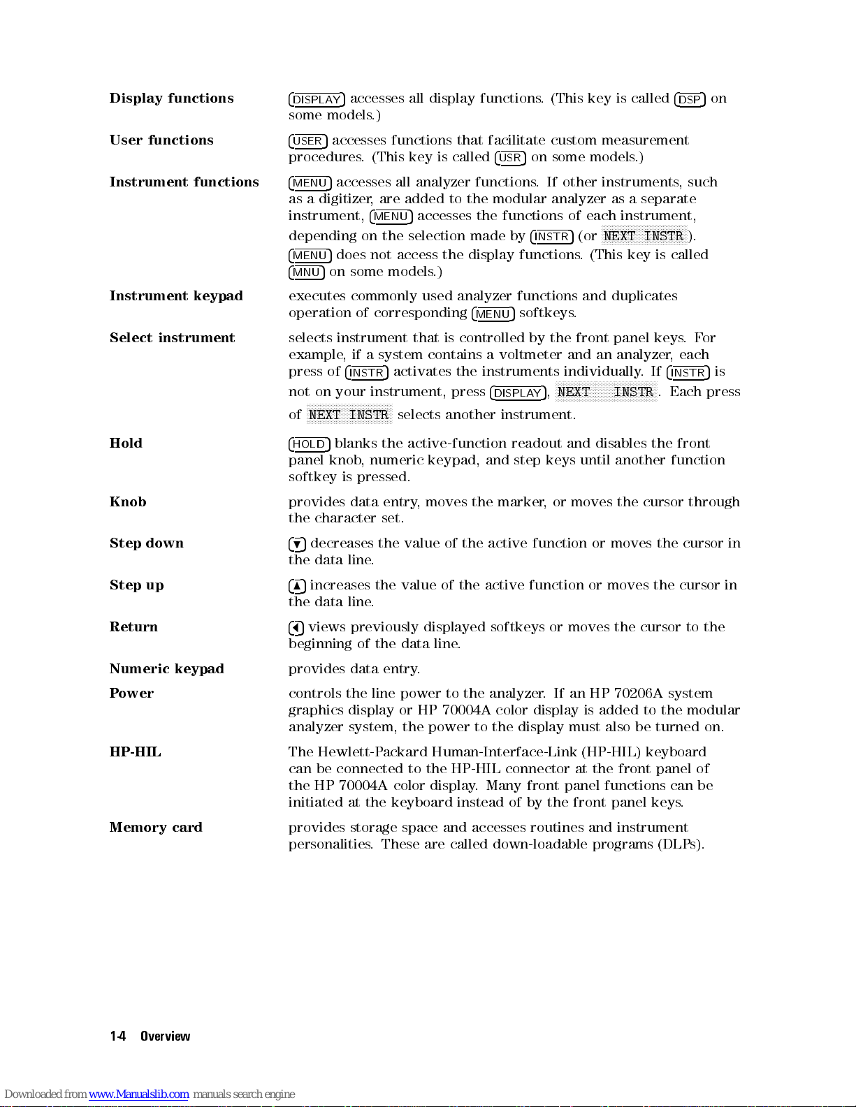
Display
functions
4
DISPLA
some models.)
5
accesses all display functions. (This key is called
Y
4
DSP
5
on
User functions
Instrument functions
Instrument
Select
Hold
Knob
Step down
keypad
instrument
4
5
accesses functions that facilitate custom measurement
USER
procedures. (This key is called
4
5
MENU
as a digitizer, are added to the modular analyzer as a separate
instrument,
depending on the selection made by
4
MENU
4
MNU
executes
operation
selects
example
press
not on your instrument, press
of
4
HOLD
panel
softkey
provides
the character set.
495
the data line.
accesses all analyzer functions. If other instruments,such
4
5
MENU
5
does
not
5
on
some
commonly
of
corresponding
instrument
,
if
a
of
4
INSTR
NNNNNNNNNNNNNNNNNNNNNNNNNNNNNNNN
NEXT
INSTR
5
blanks
knob
,
numeric
is
pressed.
data
decreases the value of the active function or moves the cursor in
accesses the functions of each instrument,
access
models
system
5
activates
selects another instrument.
the
entry
the
.)
used
that
is controlled by the front panel keys.For
contains a voltmeter and an analyzer, each
active-function
keypad,
,
moves
4
5
on some models.)
USR
NNNNNNNNNNNNNNNNNNNNNNNNNNNNNNN
4
INSTR
display
analyzer functions and duplicates
4
MENU
the
the
functions
5
softkeys
instruments
4
DISPLAY
and
marker
5
,
readout
step
keys
, or moves the cursor through
N
NNNNNNNNNNNNNNNNNNNNNNNNNNNNNNNNNNNNN
NEXT INSTR
N
5
(or
NEXT INSTR
.
(This
key
is called
.
individually
and
disables
until another function
.If
. Each press
the
4
INSTR
front
).
5
is
Step up
Return
Numeric keypad
P
ower
HP-HIL
Memory card
485
increases the value of the active function or moves the cursor in
the data line.
465
views previously displayed softkeys or moves the cursor to the
beginning of the data line.
provides data entry.
controls
graphics
analyzer system, the power to the display must also be turned on.
The Hewlett-Packard Human-Interface-Link (HP-HIL) keyboard
can be connected to the HP-HIL connector at the front panel of
the HP 70004A color display
initiated at the keyboard instead of by the front panel keys
provides storage space and accesses routines and instrument
personalities. These are called down-loadable programs (DLP
the
line
display
power
or
HP
to the analyzer. If an HP 70206A system
70004A
color
display is added to the modular
. Many front panel functions can be
.
s).
1-4 Overview
Page 28

A
ccessing
Use
the
instrument
commonly
that
surround
graphics
used
display
Analyzer
keypad
analyzer
the
display
or
the
HP
Functions
for
fast
functions
screen.
70206A
operation.
,
duplicating
The
instrument
system
with
The
the
graphics
the Instrument Keypad
instrument keypad provides easy access to
5
operation
keypad
display.
of corresponding
is not available on the HP 70205A
4
MENU
softkeys
Figure
1-2.
Instrument
K
eypad
Overview 1-5
Page 29

A
ccessing
Analyzer
Functions
with
the
4
MENU
5
K
ey
Use the
categories which are accessed with seven keys at the left side of the display screen. The
underscore indicates which group of functions is selected.
After selecting a function category, press any softkey at the right side of the display screen to
execute an analyzer function.
4
MENU
5
softkeys to access all analyzer functions. The functions are divided into seven
The
softkey
pressing
4
MENU
maps
5
.
Figure
in
Chapter 2 illustrate the location of all the softkeys that are accessed by
(Refer
to
1-3.
How
to
A
ccess
Analyzer
Chapter 4 for a description of each softkey.)
Functions
1-6 Overview
Page 30

Preparing
The
analyzer
Spectrum
connected,
step
7.
The
following
the
procedure
1.
Apply
(1).
2. Wait about 5 seconds while the analyzer performs a self-check, then press the
instrument-preset key,
3. The analyzer is operating when a trace sweeps across the display. The MEASURE indicator
LED illuminates as the sweep progresses. As an additional indicator, the green, active
(ACT) status indicators are lit on the analyzer modules, except when the
been pressed. Also, if your analyzer has more than one signal path, for example, more than
one
RF input port or more than one IF module, the green status indicator may be o on
modules
4.
If
your analyzer is sweeping, skip to step 5.
5.
If
the
analyzer
until the analyzer is activated.) If the analyzer is still not activated when power is applied,
inspect the rear panel HP-MSIB interconnections for tightness and then cycle power.
If you cannot activate the analyzer, press
conguration
address
bottom row of the map. If it is not, change the HP-MSIB row-address switch to row-address
0. See the
instructions
the
Analyzer
requires
Analyzer
most
procedure
to
power
not
analyzer
does not have an
map
HP 70000 Modular Spectrum Analyzer Installation and Verication Manual
.
proper
Installation
analyzer
activate
to
passing or processing the input signal.
is
of
by
models
provides
the analyzer, and check its hardware and error-correction status.
all mainframes and displays in the system by setting all LINE switches on
4
INSTR
not
activated
your
system.
turning
the
for
Measurements
connection
and
are
some preliminary checks for nonstandard analyzers.Follow
PRESET
4
INSTR
Move
front
of
cables
,
V
erication
ready
5or4
when
power is applied, press
5
key, press
the
panel
Manual
for
use
5
.
I-P
4
DISPLA
4
DISPLA
highlighted
knob
.
The
as shown in the
.
Once the system cables are
after they have been calibrated, continue at
5
, then press
Y
N
NNNNNNNNNNNNNNNNNNNNNNNNNNNNNNNNNN
5
,
address map
Y
rectangle
local
oscillator
HP 70000 Modular
4
DISPLA
N
N
N
N
N
N
N
N
N
N
N
NNNNNNNNNNNNNNNNNN
HP
70900B
5
4
,
INSTR
N
N
N
N
N
NNNNNNNNNNNNNNNNNNNNNNNNNNN
NEXT
to inspect the
along
the
module
INSTR
bottom
must be in the
5
key has
Y
.
(If
your
repeatedly
row
of
the
for
6.
Inspect
indicator is lit, press
the error indication. Press
other error occurs, refer to the
Verication Manual
Chapter 6 for a description of system error messages.
Note
7. Verify that the analyzer can display signals sent to the RF INPUT port. Connect the
CALIBRATOR signal to the input port, then press the following keys.
Press
the
status
For an analyzer with an external interface module for input, such as an
HP 70907A external mixer interface module
frequency range of your external mixer
indicators on the front panels of the analyzer modules. If an error (ERR)
4
DISPLAY
for installation, verication, and troubleshooting instructions. Refer to
4
INSTR PRESET
NNNNNNNNNNNNNN
Freq
NNNNNNNNNNNNNN
SPAN
NNNNNNNNNNNNNNNNNNNN
CENTER
NNNNNNNNNNN
1
NNNNNNNNNNNNNNNNNNNNNNNNNNNNNNNNNNNNNNNNN
5
,
REPORT ERRORS
4
5or4
MENU
HP 70000 Modular Spectrum Analyzer Installation and
5
(or
MHz
NNNNNNNNNNN
300
MHz
to learn what caused the error and clear
5
to reactivate the analyzer display. If any
USER
, connect any signal within the
, and tune to that signal.
4
5
)
I-P
Overview 1-7
Page 31

8.
If
your display resembles Figure 1-4, skip to step 7.
Figure 1-4. Displayed Measurement Results
If
the
input
port:
a.
Press
b.
Press
analyzer
port
N
N
does
not
you
are
using
NNNNNNNNNNNNNNNN
State
NNNNNNNNNNNNNNNNNNNNNNNNNNNNNNNNNNNNN
select input
display
may
not
the
input
be
active.Follow this procedure to activate the input
signal and has more than one input port, the
c.
Press the key corresponding to the desired input.
If
the calibrator signal still is not present on the analyzer screen, see that the interconnect
cables
Modular Spectrum Analyzer Installation and Verication Manual
instructions.
are properly installed and are tightly secured. If necessary, refer to the
for complete installation
HP 70000
1-8 Overview
Page 32

9.
UNCOR
the
execute
To execute the routine, follow this three-minute procedure:
appears
built-in
it
At the beginning of each day.
After extreme temperature changes.
After selecting a new input port.
After moving the analyzer.
Connect the CALIBRATOR signal to the input port, unless measuring signals at the input
port on an external mixer interface module (for example, HP 70907A external mixer
interface module).
at
the upper right of the graticule if your analyzer needs calibrating with
correction
only
when the analyzer requires calibration:
routine. Since the calibration routine lasts about three minutes,
Press
If
the
calibration procedure fails, check the settings of the
following
Table 1-1. Softkey Settings when Executing Calibration Procedure
Key Keystrokes
N
N
N
N
N
N
NNNNNNNNNNNNNNNNNNNNNNNNNNNNNNNN
FREQ
FOR
CAL
NNNNNNNNNNNNNNNNNNNNNNNNNNNNNNNNNNNNNNNNN
POWER FOR CAL
N
N
N
NNNNNNNNNNNNNNNNNNNNNNNNNNNNNNNNNNNNNNNNNNNN
CAL SRC INT EXT
4
INSTR
NNNNNNNNNNNNNNNNN
Amptd
NNNNNNNNNNNNNNNNNNNNNNN
CAL ALL
table
.
that Access Key
N
N
N
N
N
N
NNNNNNNNNNN
Amptd
N
N
N
N
N
N
N
N
N
N
N
N
N
N
MORE
NNNNNNNNNNNNNNNNNNNNNNNNNN
cal menu
NNNNNNNNNNNNNNNNN
Amptd
NNNNNNNNNNNNNN
MORE
N
N
N
N
N
NNNNNNNNNNNNNNNNNNNNN
cal
menu
N
N
N
NNNNNNNNNNNNNN
Amptd
NNNNNNNNNNNNNN
MORE
NNNNNNNNNNNNNNNNNNNNNNNNNN
cal menu
NNNNNNNNNNNNNNNNNNNNNNNNNNNNNNNN
cal enable
5
(or
4
5
)
I-P
5
4
MENU
Key Setting when
Using Input Port on
External Mixer Interface Module
321.4
MHz
0
35 dBm
INT EXT
softkeys
in the
Key Setting When
Using Standard RF
Input Ports
300
MHz
0
10 dBm
Verify that the
10. The analyzer is now ready for operation. To meet specications, apply power for one hour
before calibrating.
UNCOR
indicator is not present.
Overview 1-9
Page 33

Electrical
Cable
Connections
Before
good
CAUTION
Fiber-Optic Cable Connections
WARNING
When
connections be made carefully. Both the front panel tting and the source cable have a
protruding ber-optic tip. Lightwave measurements demand precision mating of awless ber
ends.
CA
making
mechanical
making
UTION
any
measurement,
condition,
To assure proper electrical connection and no connector damage, all APC 3.5
and SMA connectors must be torqued ve to eight inch-pounds. Do not exceed
eight inch-pounds.
To avoid the possibility of damage to your eyes, verify a disabled output
at the light source before any cleaning, connecting, or disconnecting of
optical system components.
measurements
The
following
light
measurements
Exposed
touch
installing
and
ber-optic
an
unprotected
a
be
sure
that
all
electrical cables and connectors are clean, in
properly
with a lightwave signal analyzer, it is important that all ber-optic
precautions
connector
.
tightened.
help
prevent
tips
are
easily
tip
.
This precaution is particularly important when
interface
ber
damage
scratched. Do not allow any object to
and
when making and breaking connections.
and
help
assure
accurate
Never insert any cleaning tool into an optical connector ferrule; this may
cause damage that can aect the optical system.
Do not touch an exposed ber-optic tip. An oily ngerprint requires cleaning
with cleaning solution.
Before any mating of ber-optic tips, clean the tips with special tape to
assure no dust or other particles remain.
In addition to tape cleaning, clean more thoroughly with cleaning solution
as routine maintenance or if measurements reveal a slightly lower than
expected power level or an increase in reection intensity noise.
Always replace the protector caps on any exposed ber-optic tip.
Cleaning Optical Connectors
The Hewlett-Packard cleaning kit, HP 15475A, includes recommended cleaning materials and
instructions for optical connectors
instructions or \Cleaning Dry Connectors" in Appendix C.
.F
or optical connector cleaning information, refer to the kit
1-10 Overview
Page 34

Making
a
Measurement
Instrument
Execute
into
a
known
analyzer
A
spectrum
normal
available
A
lightwave signal analyzer is also preset to measure the full frequency range with trace A,
using
normal peak detection, and the widest resolution bandwidth available. In addition,
an
optical signal path is selected, 5 dB of optical attenuation is set, and the power meter is
activated.
Refer to the index for a complete listing of the spectrum analyzer and lightwave signal analyzer
preset settings.
On some analyzer models, the instrument-preset key is called
The operation of the two keys is identical.
Measurement Procedure
Measurements involve tuning the instrument to place a signal on the screen, then measuring
the frequency and amplitude of the signal. Measurements can be made with either trace A, B,
or C.
An
input
Preset
the
instrument-preset
state
.
Pressing
and
lightwave
analyzer
peak
detection, 10 dB of input attenuation, and the widest resolution bandwidth
.
signal
can
be
function
the instrument-preset key,
signal
analyzer
is
preset
measured
to
using
at
dierently
measure the full frequency range with trace A, using
the
the
beginning of measurements to place the analyzer
5
,
.
following
4
INSTR PRESET
four
steps:
4
5
I-P
congures
instead of
a
spectrum
4
INSTR PRESET
5
.
1.
Set
the
span.
2.
Set
the
center
3. Set the amplitude.
4.
A
ctivate
On
all
systems
of
the
display. On models having an HP 70004A color display, the instrument keypad can be
used
interchangeably
Example 1-1.
1. Turn on the spectrum analyzer, then connect the CALIBRATOR output to the RF INPUT.
Note
2. Set the frequency span.
NNNNNNNNNNNNNN
Press
Freq
Note that the
frequency
the marker.
, measurements can be made using the softkeys located on the left and right side
Measure the calibrator signal.
To connect the calibrator signal on a lightwave signal analyzer:
Turn on the analyzer, then connect the CALIBRATOR output to the RF
INPUT on the HP 70810B lightwave section.
Press
RF INPUT) by pressing the
Continue at step 2.
, then press either the
NNNNNNNNNNNNNN
SPAN
.
with the softkeys.
NNNNNNNNNNNNNNNNNNNNNNNNNNNNNNNNNNNNNN
select input
softkey is highlighted, and also that
and select the RF signal bypass path (lightwave section
NNNNNNNNNNNNNNNNNNNNNNNNNNNNNNNNNNNNNNNNNNNN
IN 2W 70810B
NNNNNNNNNNNNNN
SPAN
softkey or
4
SPAN
softkey.
5
on the instrument keypad.
SPAN
is now displayed in the
Overview 1-11
Page 35

active-function readout on the left side of the display.To reduce the frequency span to
1 MHz, press
415
and
NNNNNNNNNNN
MHz
.
The step keys,
3. Set the center frequency.
NNNNNNNNNNNNNNNNNNNN
Press
CENTER
center-frequency
set
the
center
4. Set the amplitude.
Place the signal peak at the reference level (top graticule line) for good measurement
accuracy
4
REFERENCE
The step keys or front panel knob can also be used to adjust the reference level. Using the
knob
5. Activate the marker.
To place a marker on the highest peak contained in the trace, press either the
softkey
and
right-hand
.To adjust the signal peak to the010 dBm reference level, press either
is
the
or
the
amplitude
485
(or press
frequency
LEVEL
easiest
4
NORMAL
corner
and
495
, and front panel knob also select function values.
4
CENTER
function,
5
on the instrument keypad and then press
way
to
5
on
the
of
the
of
the
display
5
on the instrument keypad). This activates the
indicated by
to
300 MHz, press
ne-tune the signal peak to the reference level.
instrument
signal
peak
.
CENTER
keypad.
in
the
appearing in the active-function readout. To
5
5
5
,
4
3
active-function
4
0
The
,
4
0
marker
,
and
N
N
N
N
N
N
N
NNNN
MHz
.
405,415,405
displays
readout
both
area
, and
and
N
N
Amptd
NNNNNNNNNNN
dBm
.
N
NNNNNNNNNNNNNNNNNNN
Marker
the
frequency
in the upper
N
NNNNNNNNNNNNNN
or
Use Coupled Functions to Maintain Accuracy Easily
To simplify measurements, some of the analyzer functions are coupled. When the value of a
function changes, it induces a change in any function coupled to it. Coupled functions have
an automatic and manual setting, which appears as
Auto
is underscored.
When functions are uncoupled,
function annotation at the display-screen perimeter. Refer to Figure 1-6 for the location of
each \uncoupled function" asterisk.
To maintain amplitude and frequency accuracy, the resolution bandwidth, video-bandwidth,
and span functions are coupled to the sweep-time function. The resolution bandwidth lter
is the intermediate frequency (IF) lter. The video-bandwidth lter is a post-detection lter
1-12 Overview
Figure 1-5. Calibration Signal
AutoMan
Man
is underscored and an asterisk (*) appears next to the
on the key label. When coupled,
Page 36

that reduces the amplitude of high-frequency signals (noise). When coupled, the sweep time
changes as the resolution or video bandwidth, or span changes. When uncoupled, the
indicator appears at the right side of the graticule when accuracy is aected by the new
settings.
Limiting the signal level at the mixer input controls accuracy by avoiding gain compression. To
limit signal levels at the input mixer, the input attenuation is coupled to the reference level.
When coupled, the attenuation increases as the reference level increases. The limit can be
changed to increase dynamic range.
UNCAL
The video bandwidth is coupled to the resolution bandwidth, and the resolution bandwidth is
also coupled to the span. Set
the
coupling.
Resolving Closely Spaced Signals
Some measurements require adjustment of the resolution bandwidth (or IF) lter. The spectrum
analyzer traces the shape of its IF lter as it tunes past a signal. Thus, if two equal-amplitude
signals are close enough in frequency, the lter shapes can fall on top of one another and
appear as a single response. If two signals are not equal in amplitude but are still close
together
T
o resolve two signals of equal amplitude, the resolution bandwidth must be less than or equal
to the frequency separation of the two signals.For example, to resolve two signals of equal
amplitude with a frequency separation of 1 kHz, a resolution bandwidth of 1 kHz or less should
be used. Phase noise, seen along the lower skirt of the displayed response, can also aect
resolution.
Viewing Low-Level Signals
Low-level
accessed by
,
the
smaller
signals
N
N
NNNNNNNNNNNNNNNNNNNNN
BW, Swp
Decrease
the resolution bandwidth is narrowed by a factor of 10. However, to maintain amplitude
accuracy, the sweep time should be set to automatic to activate coupling.
Decrease the video bandwidth (
the
Use video averaging (
amplitude values contained in a sweep with the values obtained in the previous sweep. Since
the video-averaging function processes stored trace data, amplitude accuracy is not aected
by the sweep-time setting.
Reduce the input attenuation (
caution. Signals that are not displayed in narrow spans might still be present at the input.
Reducing the input attenuation increases the signal level to the spectrum analyzer internal
components, which are damaged permanently by 30 dBm levels or greater.For this reason,
0 dB input attenuation can be activated with the numeric keypad only.
the
sweep time should be set to automatic to activate coupling.
signal
hidden
.
resolution
NNNNNNNNNNNNNNNNNNNNNNNNNNNNNNNNNNNNNNNNNNNN
VID BW AutoMan
can
be
hidden
by
the
analyzer
N
N
N
N
bandwidth
NNNNNNNNNNNNNNNNNNNNNNNNNNNNNNNNNNNNNNNNNNNN
VID AVG On Off
RES
(
NNNNNNNNNNNNNNNNNNNNNNNNNNNNNNNNNNNNNNNNNNNN
VID BW AutoMan
NNNNNNNNNNNNNNNNNNNNNNNNNNNNNNNNNNNNNNNNN
ATTEN AutoMan
NNNNNNNNNNNNNNNNNNNNNNNNNNNNNNNNNNNNNNNNNNNN
and
RES BW AutoMan
under
noise
N
N
N
N
N
N
). The video-averaging function averages the
the response of the larger one.
oor
can
be viewed using several functions,all
NNNNNNNNNNNNNNNNNNNNNNNNNNNNNNNNNN
BW
AutoMan
). Reduce the input attenuation with
).
The
noise
). Again, to maintain amplitude accuracy,
to automatic to establish
oor drops 10 dB as
Overview 1-13
Page 37

Interpreting
The
annotation
on
Measurement
the
display
describes
Results
the
progress
and parameters of your measurements.
Figure
Figure
analyzer
Figure
A
description
Common Measurement Indicators
1-6
1-7
.
1-8
describes
describes
describes
of
each
the
annotation
additional
auxiliary
annotation is listed alphabetically, following the related illustration.
that
display
measurement indicators.
is
displayed
annotation
during most measurement procedures.
that
is
unique to a lightwave signal
Figure 1-6. Common Measurement Indicators
Active function
readout
Amplitude scale
1-14 Overview
indicates the currently active function.
species the amplitude value spanning of each major vertical
graticule division.
Page 38

Attenuation
species attenuation at the spectrum analyzer input. For a lightwave
signal analyzer, the annotation species the optical attenuation, in
optical power units, at the input of the lightwave section. Use the
N
N
N
N
N
NNNNNNNNNNNNNNNNNNNNNNNNNNNNNNNNNNNN
ATTEN
AutoMan
softkey
to change the attenuator setting.
Attenuator uncoupled
Center frequency
Marker
Marker amplitude
Marker frequency
Marker number
Reference
Resolution
Resolution
uncoupled
Span
level
bandwidth
bandwidth
indicates attenuator is not coupled to reference level. When coupled,
the attenuator changes as the reference level changes to limit signal
levels to the mixer, as specied by
attenuated
damage
indicates frequency at the center of the graticule (or active trace).
measures a point on the active trace.
describes the absolute or relative position of the active marker in
amplitude terms.
describes the absolute or relative position of the active marker in
terms of frequency, time, or period (1/frequency).
displays the number of the active marker.
indicates
indicates
indicates
Measurements
N
N
N
N
N
N
N
N
N
N
N
N
N
RES
indicates
The frequency range of one major graticule division equals span/10.
to
avoid
N
N
N
N
N
N
ATTEN
.
Set
the
absolute
the
3
the
resolution
N
NNNNNNNNNNNNNNNNNNNNNNNNNNNNNN
BW
are
AutoMan
the
frequency
amplitude
N
N
N
NNNNNNNNNNNNNNNNNNNNNNNNNNNNNNNN
AutoMan
value
dB
bandwidth
bandwidth
inaccurate
to
automatic
spanning
of
NNNNNNNNNNNNNNNNNNNNNNNNNNNNNNNNNNNNNNNNN
MAX MXR LEVEL
inaccuracies and spectrum analyzer
to
automatic
the
of
the
when
to
recouple
the
top
resolution
is
UNCAL
to
graticule
not
coupled
is displayed. Set
.
ten
major
. Signals are
recouple
line
.
lters
.
to
span.
horizontal
.
divisions
.
Start frequency
Stop
frequency
Sweep
Sweep time uncoupled
Uncalibrated
Uncorrected
Underscore
Video average counter
time
indicates frequency at left graticule edge (or beginning of active
trace).
indicates
active
indicates
spanning
indicates the sweep time is not coupled to the resolution or video
bandwidth, or span. When coupled, the sweep time changes to yield
optimum accuracy as the resolution or video bandwidth, or span
changes. Measurements are inaccurate when
NNNNNNNNNNNNNNNNNNNNNNNNNNNNNNNNNNNNNNNNNNNNNNN
SWPTIME AutoMan
indicates that the displayed amplitude of signal responses are
inaccurate. This occurs when certain analyzer settings are
decoupled. To recouple, adjust the settings for resolution bandwidth,
video bandwidth, and sweep time to automatic (A
appears when the analyzer is not calibrated with its built-in
correction factors.If
routines described in Chapter 2.
indicates the selected state of multi-state functions.
indicates the number of trace values that have been video averaged.
the
trace).
the
the
frequency
time
horizontal
at the right graticule edge (or end of the
duration of one complete sweep, or the time
scale
when frequency span equals zero.
UNCAL
to automatic to recouple.
uto).
UNCOR
is displayed, execute the calibration
is displayed. Set
Video bandwidth
indicates the 3 dB bandwidth of the post-detection video lters.
Overview 1-15
Page 39

Video
uncoupled
bandwidth
indicates
bandwidth. When coupled, the video bandwidth changes as the
resolution bandwidth changes to maintain the ratio determined by
N
NNNNNNNNNNNNNNNNNNNNNNNNNNNNNNNNNNNNNNNN
VBW/RBW RATIO
the video bandwidth is not coupled to the resolution
N
NNNNNNNNNNNNNNNNNNNNNNNNNNNNNNNNNNNNNNNNNNN
VID BW AutoMan
. Set
to automatic to recouple.
1-16 Overview
Page 40

Lightwave Signal Analyzer Measurement Indicators
Figure 1-7 illustrates additional annotation that is unique to a lightwave signal analyzer.A
description of each annotation is arranged alphabetically, following the gure. Figure 1-6 and
Figure 1-8 illustrate common analyzer annotation.
Figure 1-7. Lightwave Signal Analyzer Measurement Indicators
Overview 1-17
Page 41

Manual
indicator
responsivity
indicates
selected. The manual responsivity indicator is an asterisk (*) that is
displayed to the left of the trace annotation.
that manual mode for the responsivity function has been
Power bar
Power meter
annotation
Power meter
readout
P
ower
zeroing indicator
Trace
User
meter
annotation
power
indicator
provides a graphical display of the average optical power measured
by the power meter.
indicates whether the power meter readout is annotated in optical
or electrical units. Either
unit annotation. The units annotation of the power meter is not
coupled to the lightwave trace annotation.
displays
optical
softkeys
is displayed while osets in the power meter are being zeroed either
in automatic or manual mode. The indicator is an asterisk (*) that
is displayed to the right of the power meter annotation. Press the
NNNNNNNNNNNNNN
ZERO
indicates
electrical
respective
trace
indicates that an optical power oset has been entered using the
N
N
N
N
N
N
USR
displayed
the
current
dBm,
electrical
to
change
softkey to zero the power meter manually.
whether
units
unit
is
not
coupled
N
N
N
N
N
N
NNNNNNNNNNNNNNNNNNNNNNNNNNNNNNNN
PWR
On
to
the
the
the
.
Either
annotation.
Off
softkey
left
OPTorELEC
average power meter readout annotated in
dBm,
or watts units. Use the power meter
display annotation.
lightwave
LW
OPT
or
The
to
the
power
.
The
indicator
of
the
power meter readout.
is displayed for the respective
trace
is
LW
units
meter
annotated
ELEC
is
displayed
annotation
annotation.
is an asterisk (*) that is
of
in
the
optical
for the
lightwave
or
1-18 Overview
Page 42

Auxiliary Measurement Indicators
Figure 1-8. Auxiliary Measurement Indicators
Overview 1-19
Page 43

Alternate
level
gain compression
if
present, the gain-compression error of signal peaks below
the dashed line does not exceed the gain-compression error
of the mixer-input-level setting (usually about 1 dB for mixer
levels of05 dBm).
Alternate reference level
Amplitude oset
Box
Character set
Data line
Detection mode
Error message
Frequency oset
Function in progress
Message area
Over sweep
when present, supersedes the top graticule line.
indicates the amount of oset added to all amplitude
annotation.
selects the character for transfer to the title line or the data
line. Also marks character for modication in the data line.
provides character entry into the title line or the data line.
is a scratch pad for composing or displaying custom
functions. Also shows data entry for
functions
lights when measurements are made with optional detection
modes.
explains the type of error sensed. Refer to Chapter 6 for a
description
indicates the amount of oset added to frequency
annotation.
lights while some functions execute, such as video averaging.
Also lights when some functions change while the sweep is
progressing.
describes the progress of some functions.
provides faster sweep times, when autocoupled, by allowing
an additional 2% of frequency error and 2 dB of amplitude
error before displaying the uncalibrated indicator (UNCAL).
.
of
system
error
messages
NNNNNNNNNNNNNNNNN
TITLE
.
and
NNNNNNNNNNNNNNNNNNNNNNN
COMMAND
Space
Title
line
1-20 Overview
enters
contains messages composed with
a
space
into
the
title line or data line.
NNNNNNNNNNNNNNNNN
TITLE
.
Page 44

Interpreting
The
front
panel
indicators
and
provide
warnings
Front-P
monitor
for
hardware
anel
Indicators
the
state
of
failures
and
the analyzer during remote and local control,
operation
errors.
Figure 1-9. Front-Panel Operation Indicators
Overview 1-21
Page 45

HP-MSIB
if the HP-MSIB indicator (called I/O CHECK on some models)
turns on, inspect all module interconnections for tightness and
then cycle power. If the HP-MSIB indicator remains on, consult
the
HP 70000 Modular Spectrum Analyzer Installation and
Verication Manual
.
Status
HP-IB
Instrument
state
Denotes the active or error state. The active (ACT) indicator lights
whenever analyzer functions are accessed by pressing the
or
4
5
MENU
has sensed an error in that module.To learn the nature of the
error and its source, press
the error code and the module where the error originated. (See
Appendix C for error code denitions.) Press
the normal instrument display.
The display also has active and error indicators,anAandEthat
appear in the upper-left corner (or lower-right corner on some
models) of the display. The active indicator lights when the
4
DISPLAY
sensed
describes
is
applied,
are
indicator
lights depending on the computer instructions. The listen indicator
lights when the analyzer has received instructions or data from the
computer. The talk indicator lights when the analyzer has sent
data or instructions to the computer. The service-request indicator
lights when the analyzer has requested computer service.
describes
lights
during
indicator
UNLOCK indicators usually light when a hardware failure occurs.
If any of these indicators are lit, check all module interconnections
for tightness, then cycle power. If the indicators remains lit, refer
to the troubleshooting instructions in the
Spectrum Analyzer Installation and Verication Manual
key. The error (ERR) indicator lights when the analyzer
4
DISPLAY
5
key is pressed. The error indicator lights when an error is
by the display module.
the
remote-control status of the analyzer. When power
the
analyzer is in local control and the indicators
o.
If the analyzer is addressed by a computer, the remote
lights
and the listen, talk, or service-request indicator
the
as
the
retrace
lights
instrument
analyzer
and
whenever
operating
sweeps
between
the
5,4
state
each
frequency
frequency
analyzer
REPORT ERRORS
4
MENU
.
The
MEASURE
band
bands
.
The
is
testing
HP 70000 Modular
itself.
5
5
and
SELF
4
USER
, which lists
to return to
indicator
blanks
TEST
The
LOOP
.
5
1-22 Overview
Page 46

Using
The
measurements. With the help of
your design. Use the user softkeys when your measurements require repeated use of the same
functions. The contents of the user-key menu do not change when the analyzer is preset with
the
Presetting the User Softkeys
A preset group of softkeys facilitate the construction of menus for special measurements.To
view the factory-preset user softkeys, press
in Figure 1-10, your menu of user softkeys has been modied.
unprotected custom softkeys and reinstates the preset user softkeys (see following note).
CA
the
user
keys
4
INSTR PRESET
UTION
access
5
K
4
USER
5
key or when power is cycled.
Pressing
instrument contains diagnostics or personalities (such as scalar measurement
softkeys), these softkeys are erased when
ey
a
special
NNNNNNNNNNNNNNNNNNNNNNNNNNNNNNNNNNN
PRESET USER
set
of
analyzer functions that are designed to facilitate
NNNNNNNNNNNNNNNNNNNNNNNNNNNNNNNNNNNNNNNNNNNN
DEFINE USR KEY
removes unprotected custom softkeys.Ifyour
, you can build a set of user softkeys of
4
5
. If the softkeys do not match those shown
USER
NNNNNNNNNNNNNNNNNNNNNNNNNNNNNNNNNNN
PRESET USER
N
N
N
N
N
N
N
NNNNNNNNNNNNNNNNNNNNNNNNNNNN
PRESET USER
eliminates
is pressed.
Example
Press
1-2.
Preset
user-key
4
MENU
NNNNNNNNNNNNNNNNNNNNNNNNNNNNNNNNNNN
key control
5
menu.
N
N
N
Misc
N
N
N
N
N
N
N
N
N
NNNNNNNN
NNNNNNNN
MORE
NNNNNNNNNNNNNNNNNNNNNNNNNNNNNNNNNNN
PRESET USER
Figure 1-10. Preset User Softkeys
Creating a Custom Menu of User Softkeys
NNNNNNNNNNNNNNNNNNNNNNNNNNNNNNNNNNNNNNNNNNNN
DEFINE USR KEY
NNNNNNNNNNNNNNNNNNNNNNNNNNNNNNNNNNN
limit lines
Example 1-3.
Press
draws functions from the
softkey to the user menu as follows:
Transfer an analyzer softkey to the user-key menu.
4
MENU
NNNNNNNNNNNNNN
5
Misc
4
MENU
5
softkeys.For example,addthe
Overview 1-23
Page 47

N
N
N
MORE
NNNNNNNNNNNNNNNNNNNNNNNNNNNNNNNNNNNNNNNNNNNN
DEFINE USR KEY
softkeys
NNNNNNNNNNNNNN
Misc
N
N
limit
4
N
N
N
N
N
N
USER
N
N
N
N
NNNNNNNNNNNNNNNNNNNNNNNNNNNNNNN
N
NNNNNNNN
NNNNNNNNNNNNNNNNNNNNNNNNNNNNN
key
control
.)
NNNNNNNNNNNNNN
MORE
lines
5
(Accesses the user menu.)
(Species the
(Begins the transfer process and displays the
N
N
N
N
NNNNNNNNNNNNNNNNNNNNNNNNNNNNNNN
limit
lines
softkey for transfer.)
4
MENU
5
Press any softkey to indicate a spot for the
Figure 1-11 illustrates the location of the
user-softkey menu.
Figure 1-11. Transfer an Analyzer Softkey to User-Softkey Menu
To interrupt the transfer process, press 0 on the numeric keypad.
also be used to remove softkeys individually from the user menu. Softkeys are removed by
replacing them with blank softkeys as shown in example 1-4.
NNNNNNNNNNNNNNNNNNNNNNNNNNNNNNNNNNN
limit lines
NNNNNNNNNNNNNNNNNNNNNNNNNNNNNNNNNNN
limit lines
N
N
N
N
NNNNNNNNNNNNNNNNNNNNNNNNNNNNNNNNNNNNNNNN
DEFINE USR KEY
softkey.
softkey in the
may
1-24 Overview
Page 48

Example 1-4.
Remove a user softkey.
Press
Press the softkey you wish to blank.
Incorporating User-Dened Functions into the User-Softkey Menu
The menu of user softkeys can be congured with user-dened functions that have been stored
in internal memory. User-dened functions are created and stored most eciently with a
computer program sent to the analyzer via HP-IB. Refer to the
Analyzer Programming Manual
modied
Restricting Instrument Operation to User Softkeys
If you wish to restrict analyzer operation to the user softkeys, execute the
programming command via HP-IB, or execute
CA
or
UTION
stored
4
5
USER
Any blank softkey
NNNNNNNNNNNNNNNNNNNNNNNNNNNNNNNNNNNNNNNNNNNN
DEFINE USR KEY
HP 70000 Modular Spectrum
. However, user-dened functions can also be created,
using
information
Once
USERLOCK
either by executing the
computer
the
softkeys must be transferred to the user-key menu before
executed, if a computer is unavailable. (See Example 1-3.)
4
MENU
,
or
by
5
key. Since
is
on,
using
from
the
\Programming-Related Softkey Descriptions".
USERLOCK ON
5
N
N
N
N
N
N
N
N
NNNNNNNNNNNNN
softkeys
the
4
MENU
USERLOCK OFF
N
N
COMMAND
the
USERLOCK ON
using these front panel controls:
can
be
reenabled
command via HP-IB with the use of a
softkeys
deactivates the
which
are
4
MENU
normally
USERLOCK ON
two
ways
accessed
5
key, the
USERLOCK ON
only
N
N
N
N
NNNNNNNNNNNNNNNNNNN
COMMAND
is
,
with
Example 1-5.
1.
A
dd
the
Caution
2.
Press
3.
Press
characters contained in the alphabet shown on the analyzer display. Press
enter each letter into the data line. As each letter is entered, it appears in the data line at
the bottom of the analyzer screen. (The character for \space" is located after
4.
After
USERLOCK ON
To reactivate the
computer program. Use the step-up key,
For additional information, see \User-Dened Softkey Descriptions" and \Programming-Related
Softkey Descriptions" in Chapter 3.
Disable the
N
N
N
N
N
N
N
NNNNNNNNNNNNNNN
N
COMMAND
above
.)
5
.
4
USER
NNNNNNNNNNNNNNNNNNNNNN
N
COMMAND
USERLOCK ON
,
then
function.
4
MENU
4
5
MENU
softkey
spell
is entered into the data line, press
5
key, execute
softkey.
to
the user menu, following the procedure in Example 1-3. (See
out
USERLOCK
USERLOCK OFF
ON by positioning the cursor underneath the
using the preceding procedure or a
5
to position the cursor at the end of the data line.
4
8
NNNNNNNNNNNNNNNNNNNNNNNNNNNNNNNNNNNNNNNNNNNNNNNNNNNNN
ENTER COMMAND
NNNNNNNNNNNNNNNNNNNNNNNNNNNNNNNNNN
N
SELECT CHAR
Z
.)
to execute the
to
Overview 1-25
Page 49

Using
The
instrument in the analyzer system. Display operation is described in documentation for the
HP 70004A color display, HP 70205A graphics display, and HP 70206A system graphics display
displays. Some commonly used features are described here for your convenience.
N
NNNNNNNNNNNNNNNNNNNNNNNNNNNNNNNNNNNNNNNNNNN
DISPLAY PRESET
user
N
N
N
NEXT
instrument
instrument in the system. If the analyzer is the only instrument in the system,
accesses the analyzer.
NNNNNNNNNNNNNNNNN
PRINT
connected to the display HP-IB port.
NNNNNNNNNNNNNN
PLOT
connected to the display HP-IB port.
N
N
N
REPORT
lists the name and HP-MSIB address of the module that produced the error.Todisplay
measurement results again, press
descriptions.
NNNNNNNNNNNNNNNNNNNNNNNNNNNNNNNNNNNNNNNNN
display tests
version).
dot-generator
N
N
N
INTEN
intensity.
the
4
DISPLA
4
DISPLAY
N
N
N
N
NNNNNNNNNNNNNNNNNNNNNNNNN
N
N
N
N
N
N
N
N
N
N
N
N
5
softkeys control the functions of the display module, which is a separate
softkeys
INSTR
reproduces the displayed results on a peripheral, vector-type plotter,whenitis
NNNNNNNNNNNNNNNNNNNNNNNNNNNNNNNN
N
N
N
NNNNNNNNNNNNNNNNNNNNNNNNNN
to
(select
in the system, one at a time. Each press of
reproduces displayed results on a peripheral, raster-type graphics printer when it is
ERRORS
NNNNNNNNNNNNNNNNNNNNNNNNNNNNNNNNNNNNNNNNN
display
Press
release
ADJUST
5
K
ey
Y
sets the format of the display to its preset state and assigns the
the
last
instrument
instrument)
NNNNNNNNNNNNNNNNNNNNNNNNNNNNNNNN
NEXT INSTR
lists
the
code
accesses display diagnostics and identies the display rmware (ROM
tests
number.
adjusts
the
intensity
in the system that displayed measurement results.
links
the display and front panel controls with each
does not access the display.
and description of any operation or hardware error,and
4
5or4
MENU
NNNNNNNNNNNNNNNNNNNNNNNNNNNNNNNN
DISPLAY
,
of
the
5
USER
ID
to
display
N
N
N
NNNNNNNNNNNNNNNNNNNNNNNNNNNNN
NEXT
INSTR
. See Appendix D for error-code
view
the
display
. Press the key, then turn the knob to vary
accesses the next
rmware
NNNNNNNNNNNNNNNNNNNNNNNNNNNNNNNN
NEXT INSTR
version
4
MENU
and
5
and
The color of the elements of the analyzer display, such as the graticule or the annotation, can
be
varied
to access them.
NNNNNNNNNNNNNNNNNNNNNNNNNNNNNNNN
BACKGROUND
NNNNNNNNNNNNNNNNNNNNNNNNNNNNN
GRATICULE
NNNNNNNNNNNNNNNNNNNNNNN
TRACE A
NNNNNNNNNNNNNNNNNNNNNNN
TRACE B
NNNNNNNNNNNNNNNNNNNNNNN
TRACE C
NNNNNNNNNNNNNNNNN
LINES
N
NNNNNNNNNNNNNNNNNNNNNNNNNNNNNNNNNNNNN
TITLE/ACTIVE
NNNNNNNNNNNNNNNNNNNNNNNNNNNNNNNN
ANNOTATION
NNNNNNNNNNNNNNNNNNNN
ADVISE
NNNNNNNNNNNNNNNNNNNN
ERRORS
1-26 Overview
by
pressing
(for limit lines)
(for advisory messages)
(error messages)
any of the following keys. Press
4
DISPLAY
N
N
adjust
5
,
N
N
N
N
N
N
NNNNNNNNNNNNNNNNNNNNNNNNNNNNNN
color
N
,
N
N
N
N
edit
N
N
N
NNNNNNNNNNNNNNNNNNNNNNNN
color
Page 50

N
N
N
N
N
N
NNNNNNNNNNNNNNNNN
MARKERS
NNNNNNNNNNNNNNNNNNNNNNNNNNNNNNNN
KEY LABELS
The
above
N
N
N
N
N
N
N
N
NNNNNNNNNNNNNN
N
HSL/RGB
N
N
N
N
NNNNNNN
HUE
NNNNNNNNNNNNNNNNNNNNNNNNNNNNNNNN
SATURATION
NNNNNNNNNNNNNNNNNNNNNNNNNNNNNNNN
LUMINOSITY
N
N
N
N
N
N
N
N
NNN
RED
NNNNNNNNNNNNNN
BLUE
NNNNNNNNNNNNNNNNN
GREEN
softkeys
.
The
access the following color-editing softkeys, depending on the setting of
HP
70004A
Color
Display User's Guide
describes their operation.
Overview 1-27
Page 51

A
ccessing
Custom,
User-Dened
Functions
Unique
NNNNNNNNNNNNNNNNNNNNNNNNNNNNNNNNNNNNNNNNN
ENTER COMMAND
internal memory.To view functions stored in internal memory, press
Stored functions are listed along the right side of the display. Press the softkeys to execute
each function.
functions
N
N
N
NNNNNNNNNNN
MENU
NNNNNNNNNNNNNN
Misc
NNNNNNNNNNNNNN
MORE
N
N
N
NNNNNNNNNNNNNNNNNNNNNNNNNNNNNNNN
execute
DLP
can
be
stored
. Functions and personalities can also be loaded from the memory card into
(execute \down-loadable" program)
in
internal
memory
with computer programs or
1-28 Overview
Page 52

A
ccessing
the
Memory
Card
Memory
HP
Insert
the card (2 cm) is exposed. Improper insertion can produce error messages.
cards
70004A
the
color
card
are
display
with
available
or
the
arrow
for
external
connected
facing
memory
to
it
up
into the slot. When correctly installed, a portion of
when
via HP-MSIB.
the analyzer is installed in the
Figure 1-12. Inserting the Memory Card
The memory card requires power. Items stored in the memory card remain as long as the
card has sucient power. The HP 70004A color display provides power to the card when it
is installed. The HP 70004A color display supplies power to the memory card only when the
display is turned on. When the card is removed or the display is turned o, power is supplied
by a battery within the memory card.
Change the memory-card battery every two years. On new cards, the time of installation is
engraved on the side of the card. The rst digit refers
refer to the month, and the last digit refers to the week. F
battery was installed during the third week of October in 1993.
To change the battery
1. Install the memory card into the HP 70004A color display.
2. Locate the groove of the battery clip at the front edge of the card.
3. Gently pry the battery clip out of the card. The battery ts inside the clip.
4. Replace the battery, making sure the plus (+) sign on the battery is on the same side as the
plus sign on the clip.
5. Insert the battery clip into the memory card, holding the clip as oriented in the following
gure.(Face the open edge of the clip toward the write-protect switch on the memory
card.)
, follow this procedure:
to the year. The next two characters
or example, 3OC3 indicates the
Overview 1-29
Page 53

6. Write the date that the battery was replaced on the memory-card label, to remind you when
the battery should be replaced.
CAUTION
Formatting a Memory Card
New
memory
memory
format used memory cards, but note that the
Follow this procedure:
1. Insert the memory card.
2. Specify the location of the memory card. If the card is in the HP 70004A color display, press
3.
CA
cards
NNNNNNNNNNNNNN
Misc
,
N
N
N
N
N
N
N
N
N
N
N
NNNNNNNNNNNNNNNNNNNNNNNNNNN
HP-MSIB
2
32).
N
FORMAT
Press
UTION
N
Memory
battery
battery
all
before
cards
with the logical-interchange-le (LIF) format.
NNNNNNNNNNNNNN
MORE
N
N
N
NNNNNNNNNNNNNNNNNNNNNNNNNNNNNNNNNNNNNN
HP-MSIB
,
CARD
,
N
N
N
N
N
N
N
N
N
N
NNNNN
N
N
N
N
N
N
FORMAT
select the desired memory before executing
selected automatically when power is applied.
cards
must
be
installed
is
removed.
. If the battery is removed while the card is not installed in the display,
data in the memory card is lost. Store memory-card les on another device
changing the battery, when extra care is appropriate.
need
to
be formatted before use. Use the
CARD
then
enter
N
N
N
N
N
N
NNNNNNNN
erases
Be
sure
.
If
the
card
its
HP-MSIB address (that is, the column address + row address
the
contents
in an HP 70004A color display when the
the display is turned on before removing the
N
N
N
N
N
N
N
NNNNNNNNNNNN
N
FORMAT
N
N
N
N
NNNNNNNNNNNNNNNN
FORMAT
formatting process destroys all stored data
is
in
of
another
the
currently
HP-MSIB
selected memory. Be sure to
NNNNNNNNNNNNNNNNNNNN
FORMAT
softkey
can
device
. Internal memory is
to
format
also be used to
NNNNNNNNNNNNNN
press
Misc
,
new
.
NNNNNNNNNNNNNN
MORE
,
,
1-30 Overview
Page 54

Softkey Menu Maps
2
The following softkey menus are accessed by pressing the
softkeys located along the left side of the display. The menu softkeys are displayed as separate
menu pages. Press the
Table 2-1 summarizes the functions accessed by each of the top-level
Table 2-1. Function Categories Accessed by Top-Level Keys
Top-Level
Menu
Softkeys
NNNNNNNNNNNNNN
Freq
NNNNNNNNNNNNNNNNN
Amptd
N
N
N
N
N
N
N
N
Marker
N
N
N
N
N
N
N
N
BW,Swp
N
N
N
N
N
N
N
N
Traces
N
N
NNNNNNNNNNNNNNN
State
NNNNNNNNNNNNN
N
Misc
N
N
N
N
N
N
N
NNNNNNNNNN
N
N
N
N
N
N
N
N
NNNNNN
NNNNNNNNNNNNNN
MORE
softkeys to access additional menu pages.
Instrument Function Categories
Frequency
Amplitude
meter
NNNNN
Lightwave
Measurement
Bandwidth
processing
Instrument
processing
External mixer, Instrument state,Memory, Preamplier,
Preselector, Signal path selection, Tracking generator and
source
Amplitude correction, Display, Limit lines, Memory,
Programming, Service, User denition
selection,
selection,
markers
range
selection,
state
,
Memory
Preselector
Calibration,
,
Marker
adjustment,
Sweep
,
4
MENU
,
Signal
Lightwave
annotation,
Marker
and
trigger
Signal
detection,
5
key and then pressing the
4
5
MENU
identication
Marker
utility
selection,
Trace
keys.
mode
,
positioning,
Trace
P
ower
The
softkey
softkeys on the left side of the display, reading from the top softkey to the bottom softkey.
menu
illustrations
in
this chapter are arranged in the same sequence as the
Softkey Menu Maps 2-1
Page 55
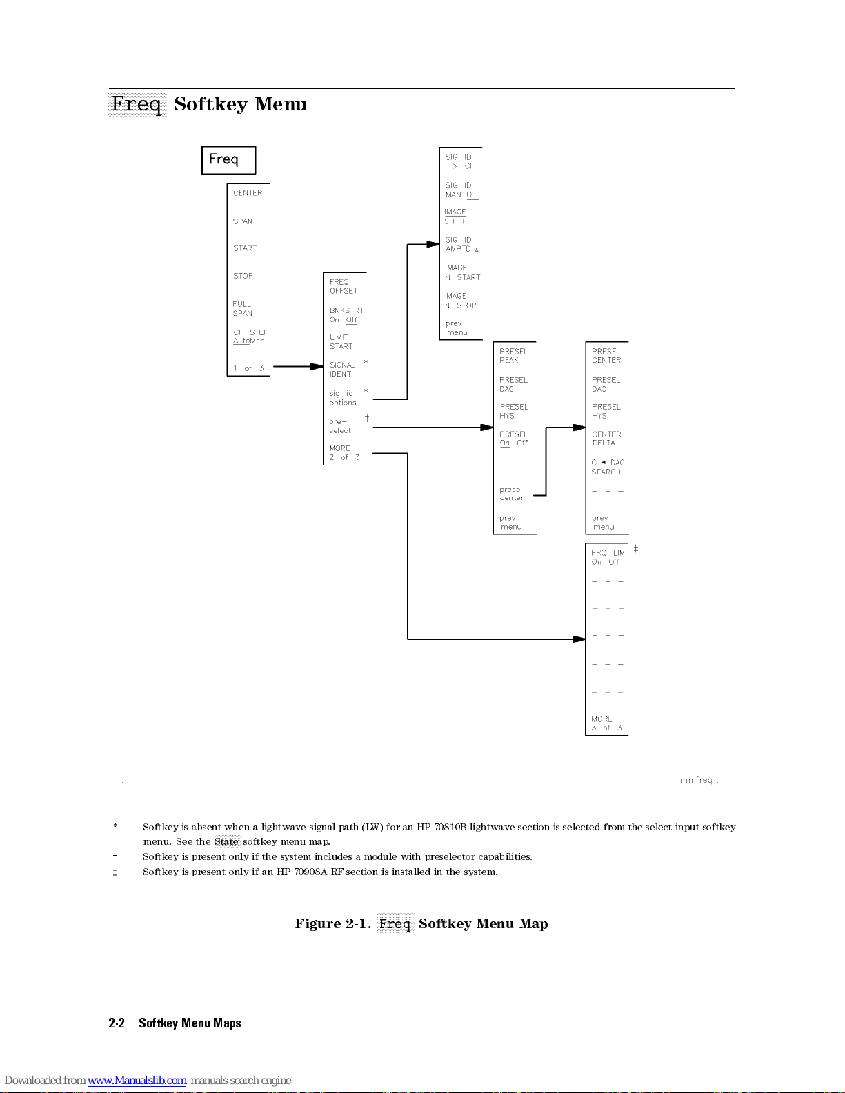
aaaaaaaaaaaaaaaaaaaaaa
Freq
Softkey
Menu
* Softkey is absent when a lightwave signal path (L
menu. See the
y
Softkey is present only if the system includes a module with preselector capabilities.
z
Softkey is present only if an HP 70908A RF section is installed in the system.
2-2 Softkey Menu Maps
??????????
State softkey menu map.
Figure 2-1.
W) for an HP 70810B lightwave section is selected from the select input softkey
NNNNNNNNNNNNNN
Freq
Softkey Menu Map
Page 56

aaaaaaaaaaaaaaaaaaaaaaaaaa
Amptd
Softkey
Menu
N
N
N
N
N
N
N
N
N
N
Amptd
NNNNNNN
Softkey
Menu
????
?????????????????????????????
?
*
LINEAR Vlt Pwr is replaced by the
????????????????????????????????????
?
the
LW MODE OptElec softkey.
y
Softkey is deleted when the optical mode for a lightwave signal path (L
z
Softkey is present only if the system includes a module with power meter capabilities, such as the HP 70810B lightwave section.
x
Softkey is present when a lightwave signal path (LW) is selected from the select input softkey menu. See the
menu map.
k
Softkey is absent when a lightwave signal path (LW) is selected from the select input softkey menu. See the
map.
# Softkey is present when the electrical mode for a lightwave signal path (LW) is selected with the
????
???????????
?
LINEAR softkey when the optical mode for a lightwave signal path (L
W) is selected with the
Figure 2-2.
NNNNNNNNNNNNNNNNN
Amptd
Softkey Menu Map
W) is selected with
????????????????????????????????????
?
LW MODE OptElec softkey
??????????
State softkey
??????????
State softkey menu
?????????????????????????????????????
LW MODE OptElec softkey.
Softkey Menu Maps 2-3
.
Page 57

aaaaaaaaaaaaaaaaaaaaaaaaaaaaaaa
Marker
Softkey
Menu
?????????????????????????????????
?
SIG TRK On O is replaced by
*
softkey menu. See the
?????????????????????????????????
y
MINIMUM POINT is replaced by
softkey menu. See the
2-4 Softkey Menu Maps
??????????
State softkey menu map.
??????????
State softkey menu map.
?????????????????????????????????
?
RIN SYS On O when a lightwave signal
????????????????????????????????????
REL PWR On O when a lightwave signal path (L
Figure 2-3.
NNNNNNNNNNNNNNNNNNNN
Marker
Softkey Menu Map
path (LW) is selected from the select input
W) is selected from the select input
Page 58
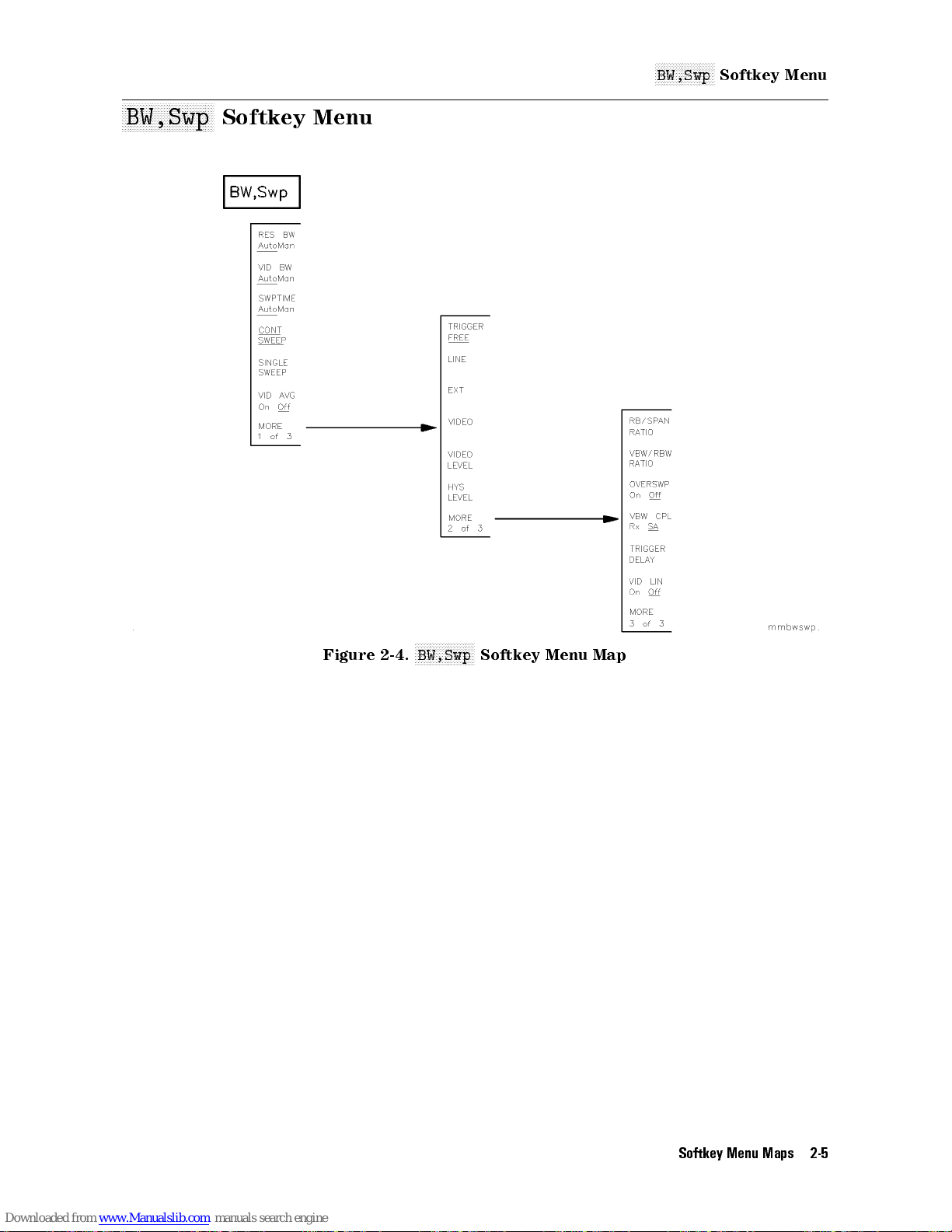
aaaaaaaaaaaaaaaaaaaaaaaaaaaaaaa
BW,Swp
Softkey
Menu
N
N
N
N
N
N
N
N
N
N
NNNNNNNNNN
BW,Swp
Softkey
Menu
Figure 2-4.
NNNNNNNNNNNNNNNNNNNN
BW,Swp
Softkey Menu Map
Softkey Menu Maps 2-5
Page 59

aaaaaaaaaaaaaaaaaaaaaaaaaaaaaaa
Traces
Softkey
Menu
??????????????????????????????????????
* If the
y
z
2-6 Softkey Menu Maps
?
VIEW A BLANK A softkey is present, press
??????????????????
?
STORE A softkey is replaced by
These softkeys are only available after pressing
?
??????????????????????????????????????
?
VIEW A BLANK A when
Figure 2-5.
CLEAR WRT A to return the
????????????????????????????????
?
3-DIMEN On O .
NNNNNNNNNNNNNNNNNNNN
Traces
??????????????????????????????
??????????????????
?
STORE A is pressed.
Softkey Menu Map
??????????????????
?
STORE A softkey.
Page 60

aaaaaaaaaaaaaaaaaaaaaaaaaa
State
Softkey
Menu
N
N
N
N
N
N
N
N
N
N
State
NNNNNNN
Softkey
Menu
* The softkey is present only if there are multiple input signal paths available. The number of signal path inputs displayed after
pressing the softkey is dependent on the number of RF and lightwave modules installed in the system.
y
The model number for each module is displayed below the input signal designation. The menu illustrates the input signal
modules from a HP 71400C lightwave signal analyzer.
z
Two inputs are displayed for each HP 70810B lightwave section that is installed in the system. TheW input is displayed below
the lightwave (L
???????????????????????????????????
IN 2W 70810B are replaced by
x
Softkey is present only if the system includes a module with preselector capabilities
k
Softkey is present only if the system includes a module with tracking generator capabilities.
W) input. When an HP 70910A RF section is in the system, the softkeys
Figure 2-6.
??????????????????????????????????
IN 1 RF 70910A and
NNNNNNNNNNNNNNNNN
State
Softkey Menu Map (1 of 5)
???????????????????????????????????
IN 2 EM 70910A .
???????????????????????????????????
IN 1 L
.
W 70810B and
Softkey Menu Maps 2-7
Page 61
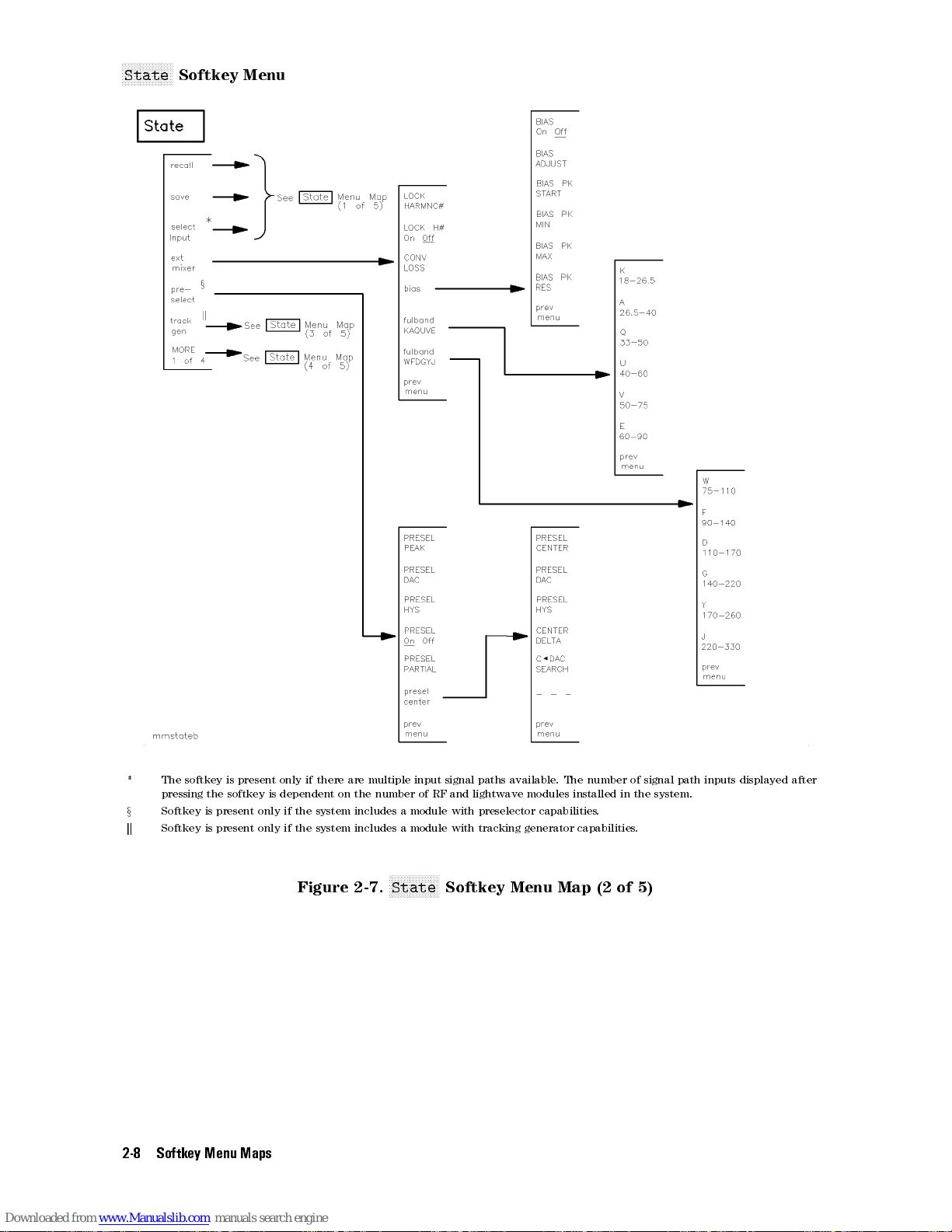
N
N
N
N
N
N
N
N
N
N
NNNNNNN
State
Softkey
Menu
* The softkey is present only if there are multiple input signal paths available. The number of signal path inputs displayed after
pressing
the
softkey
is
dependent on the number of RF and lightwave modules installed in the system.
x
Softkey is present only if the system includes a module with preselector capabilities.
k
Softkey is present only if the system includes a module with tracking generator capabilities.
Figure 2-7.
2-8 Softkey Menu Maps
NNNNNNNNNNNNNNNNN
State
Softkey Menu Map (2 of 5)
Page 62

N
N
N
N
N
N
N
N
N
N
State
NNNNNNN
Softkey
Menu
* The softkey is present only if there are multiple input signal paths available. The number of signal path inputs displayed after
pressing the softkey is dependent on the number of RF and lightwave modules installed in the system.
x
Softkey is present only if the system includes a module with preselector capabilities.
k
Softkey is present only if the system includes a module with tracking generator capabilities.
# Softkey is present only if the system includes a tracking generator module with modulation capabilities.
Figure 2-8.
NNNNNNNNNNNNNNNNN
State
Softkey Menu Map (3 of 5)
Softkey Menu Maps 2-9
Page 63

N
N
N
N
N
N
N
N
N
N
NNNNNNN
State
Softkey
Menu
* The softkey is present only if there are multiple input signal paths available. The number of signal path inputs displayed after
pressing
the
softkey
is
dependent
y
The model number for each module is displayed below the input signal designation. The menu illustrates the input signal
modules from a HP 71400C lightwave signal analyzer system.
z
Two inputs are displayed for each HP 70810B lightwave section that is installed in the system. TheW input is displayed below
the lightwave (L
???????????????????????????????????
IN 2W 70810B are replaced by
x
Softkey is present only if the system includes a module with preselector capabilities
k
Softkey is present only if the system includes a module with tracking generator capabilities.
** Softkey is present only if the system includes a preamplier module
yy
Softkey is present only if the system includes an HP 70700A digitizer.
zz
Softkey is present only if an HP 70908A RF section is installed in the system.
2-10 Softkey Menu Maps
W) input. When an HP 70910A RF
Figure 2-9.
on
the number of RF and lightwave modules installed in the system.
???????????????????????????????????
??????????????????????????????????
IN 1 RF 70910A and
section is in the system, the softkeys
NNNNNNNNNNNNNNNNN
State
Softkey Menu Map (4 of 5)
???????????????????????????????????
IN 2 EM 70910A .
.
IN 1 L
.
W 70810B and
Page 64

N
N
N
N
N
N
N
N
N
N
State
NNNNNNN
Softkey
Menu
zz
Softkey
is present only if an HP 70908A RF section is installed in the system.
xx
Pressing this softkey causes all display links to be broken. To establish new display links, press
Figure
2-10.
NNNNNNNNNNNNNNNNN
State
Softkey
Menu
Map
(5
of 5)
4
DISPLA
5
and
4
NEXT
Y
INSTR
5
.
Softkey Menu Maps 2-11
Page 65

aaaaaaaaaaaaaaaaaaaaaa
Misc
Softkey
Menu
?????????????????????????
* When
y
2-12 Softkey Menu Maps
?
DELETE or
Pressing softkey provides a sequence of three editing functions. Press
?????????????????????????
Press
INSERT or
... softkey is present,
... to access the delete editing function. Press
Figure 2-11.
????????????????????????????
?
SELECT CHAR is replaced by
??????????????????????????
DELETE or
NNNNNNNNNNNNNN
Misc
Softkey Menu Map (1 of 2)
?????????????????????????????
?
DELETE CHAR .
????????????????????????????
REPLACE or... to access the insert editing function.
... to access the replacement editing function.
Page 66
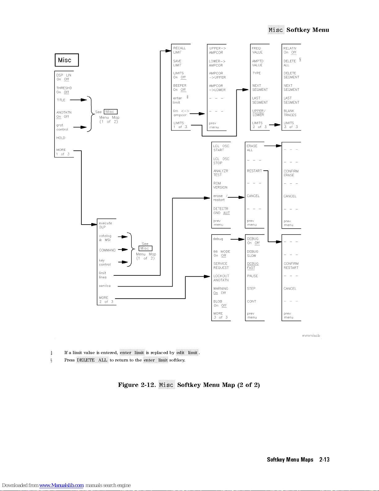
N
N
N
N
N
N
N
Misc
N
N
N
NNNN
Softkey
Menu
?????????????????????
z
If a limit value is entered,
x
???????????????????????????
Press
DELETE ALL to return to the
enter limit is replaced by
Figure 2-12.
???????????????????
NNNNNNNNNNNNNN
Misc
edit limit .
Softkey Menu Map (2 of 2)
?????????????????????
enter limit softkey.
Softkey Menu Maps 2-13
Page 67

Page 68

3
SoftKey Quick Reference
The following tables show the softkeys that can be accessed by each of the seven top-level
softkeys that appear on the left side of the display when
Generally, a softkey that is displayed in inverse video indicates that the function is enabled.
When an active function is enabled, it is always displayed in inverse video. The use of an
underline within a softkey display indicates that a specic functional state for the softkey is
selected.
Refer to \Functional Grouping Denitions" for detailed descriptions of each functional grouping
in the following tables.
4
MENU
5
is pressed.
SoftKey Quick Reference 3-1
Page 69

Table 3-1. SoftKey Quick Reference, Organized by Function
Menu
K
ey
A
ctive-Trace
NNNNNNNNNNNNNNNNNNNNNNNNNNNNNNNNNNNNNNNNNNNN
3-DIMEN On Off
NNNNNNNNNNNNNNNNNNNNNNN
A
XCH
NNNNNNNNNNNNNNNNNNNNNN
N
A XCH C
NNNNNNNNNNNNNNNNNNNNNNNNNNNNNNNNNNNNNNN
A6(A0B)0C+DL
N
N
N
A
NNNNNNNNNNNNNNNNNNNNNNNNNN
A6A0B+DL
N
N
N
A
NNNNNNNNNNNNNNNNNNNNNNNNNN
A6A0C+DL
NNNNNNNNNNNNNNNNN
A6A0C
NNNNNNNNNNNNNNNNNNNNNNNNNNNNNNNNNNNNN
A
NNNNNNNNNNNNNNNNNNNNNNNNNNNNNNNNNNNNNNNNNNN
A6A*DL/(A+B+C)
N
N
NNNNNNNNNNNNNNNNNNNNNNNNNN
A6A*DL/B)
N
NNNNNNNNNNNNNNNNNNNNNNNNNN
N
A6A*DL/C)
N
N
N
A
N
N
N
A-B+DL
NNNNNNNNNNNNNNNNNNNNNNNNNNNNNNNNNNNNNNNNN
A-B->A On Off
N
N
N
A<-A+B
NNNNNNNNNNNNNNNNNNNNNN
N
B
NNNNNNNNNNNNNNNNNNNNNNN
B<-B-DL
N
NNNNNNNNNNNNN
C<-B
NNN
CLEAR WRT A
NNNNNNNNNNNNNNNNNNNNNNNNNNNNNNNNNNN
CLEAR WRT B
NNNNNNNNNNNNNNNNNNNNNNNNNNNNNNNNNN
N
CLEAR WRT C
NNNNNNNNNNNNNNNNNNNNNNNNNNNNNNNNNNN
HORZ OFFSET
NNNNNNNNNNNNNNNNNNNNNNNNNNNNNNNNNNNNNN
LINES On Off
B
N
NNNNNNNNNNNNNNNNNNNNNNNNNN
6
(A0B)0C
N
N
N
N
NNNNNNNNNN
6
A
0
B
6
A*DL/(A+B)
N
N
N
N
N
NNNNNNNNNNNNNNNNNNNNNNNNNNNNNNNN
6
DL*(A+B)/C)
N
N
N
N
N
N
N
N
N
N
N
NNNNNNNNNNNNNNNNNNNNNNNNNNN
N
NNNNNNNNNNNNNNNN
XCH
C
NNNNNNNNNNNNNNNNNNNNNNNNNNNNNNNN
Processing Functions
On
Off
Denition
Turn on or o the three-dimensional trace display capability.
Exchanges
Exchanges the contents of the trace A and C registers.
Performs trace math (A0B)0C+DL7A with each sweep.
P
erforms
Performs trace math A0B+DL7A with each sweep.
P
erforms
Performs trace math (A0C)+DL7A with each sweep.
Performs trace math A0C7A with each sweep.
P
erforms
Performs trace math A*DL/(A+B+C)7A with each sweep.
Performs trace math A*DL/B7A with each sweep.
Performs trace math A*DL/C7A with each sweep.
P
erforms
Subtracts
the
display
Subtracts trace B from trace A point by point, then stores the
results in trace A.
Adds traces A and B point by point, then stores the results in trace
A.
Exchanges
Subtracts the value of the display line from trace B, then stores the
result in trace B.
Stores the results of trace B in trace C.
Continuously displays any signals detected at the spectrum
analyzer input for the related trace.
Continuously displays any signals detected at the spectrum
analyzer input for the related trace
Continuously displays any signals detected at the spectrum
analyzer input for the related trace.
Select the horizontal oset of the three-dimensional trace display.
Changes the appearance of displayed trace information.
the
contents
trace math (A0B)0C7A with each sweep.
trace
math
trace
math
trace
math
trace
B
from
line
,
and
the
contents
of
the
trace
A
and
B
registers.
A
0B7
A with each sweep.
A*DL/(A+B)
DL*(A+B)/C7A with each sweep.
trace
then
stores
of
the
A
7
point
the
trace
A
with
by
results
B
.
each
point,
in
and
C registers.
sweep
adds
trace A.
.
the value of
3-2 SoftKey Quick Reference
Page 70

Table 3-1. SoftKey Quick Reference, Organized by Function (continued)
Menu Key Denition
Active-Trace Processing Functions | Continued
N
N
N
NNNNNNNNNNNNNNNNNNNNNNNNNNNN
N
MAX
HOLD A
N
N
N
N
N
N
N
NNNNNNNNNNNNNNNNNNNNNNNN
N
MIN
HOLD
A
NNNNNNNNNNNNNNNNNNNNNNNNNNNNNNNNNNNNNNNNNNN
N
PERSIST
NNNNNNNNNNNNNNNNNNNNNNN
STORE A
NNNNNNNNNNNNNNNNNNNNNNNNNNNNNNNNNNNNNN
TRACE LENGTH
NNNNNNNNNNNNNNNNNNNNNNNNNNNNNNNNNNN
VERT OFFSET
NNNNNNNNNNNNNNNNNNNNNNNNNNNNNNNNNNNNNNNNNNNN
VID
NNNNNNNNNNNNNNNNNNNNNNNNNNNNNNNNNNNNNNNNNNNN
VIEW A BLANK A
N
N
N
N
N
N
NNNNNNNNNNNNNNNNNNNNNNNNNNNNNNNN
oneshot
N
N
N
N
N
N
N
N
N
N
trace
N
N
N
N
N
N
N
N
N
N
trace
NNNNNNNNNNNNNNNNNNNNNNNNNNNNNNNNNNNNNNNNN
trace logmath
On
AVG
On
math
N
N
N
NNNNNNNNNNNNNNNNNNNNNN
A
B
N
N
NNNNNNNNNNNNNNNNNNNNNNNNNNNNN
C
linmath
Off
Off
Compares
each
then
Compares
each
then
Simulates
trace
Stops the updating of the Trace A, stores the trace data in reserved
memory, then activates the
Varies the number of points in a trace from 3 to 1024.
Select the vertical oset of the three-dimensional trace display.
Executes
level,
analog
Selects two functions. When set to view, stored trace data is
displayed. When set to blank, stored trace data is blanked from
the display, but remains in reserved memory. Trace B and Trace C
have a corresponding view and blank softkey function.
A
ccesses
Selects
A
ccesses
Accesses log math active-trace processing function softkeys.
the current amplitude value of each point on a trace to
corresponding value detected during the previous sweep,
retains the maximum values.
the
current
corresponding
retains
information.
but
the
analog
a
digital-averaging
does
not
characteristic
oneshot math active-trace processing function softkeys.
the
active
linear
math
amplitude
value
minimum
displays
aect
of
the
trace
for
active-trace
detected
by
the
value
of each point on a trace to
during
values.
changing
NNNNNNNNNNNNNNNNNNNNNNNNNNNNNNNNNNNNNNNNNNNN
VIEW A/BLANK A
routine
sweep
analyzer
the
trace-processing
the
that
reduces
time
,
.
processing
the previous sweep,
appearance
softkey.
bandwidth,
functions
function
the
noise-oor
or
softkeys.
of
displayed
any
.
other
SoftKey Quick Reference 3-3
Page 71

Table 3-1. SoftKey Quick Reference, Organized by Function (continued)
Menu Key Denition
Amplitude Functions
N
N
N
NNNNNNNNNNNNNNNNNNNNNNNNNNNNNNNNNNNNNNNN
N
A
METER On Off
NNNNNNNNNNNNNNNNNNNNNNNNNNNNNNNNNNNNNNNNNNNNNNN
A UNITS AutoMan
N
N
N
N
N
N
N
N
N
N
NNNNNNNNNNNNNNNNNNNNNNNNNNNNNNNNNN
AMP
REF
OFFSET
NNNNNNNNNNNNNNNNNNNNNNNNNNNNNNNNNNNNNNNNN
AMPCOR On Off
N
N
N
N
NNNNNNNNNNNNNNNNNNNNNNNNNNNNNNNNNNNNN
ATTEN
NNNNNNNNNNNNNNNNNNNNNNNNNNNNNNNNNNNNNNNNNNN
N
CPL AVG On Off
N
N
N
INPUT
NNNNNNNNNNNNNNNNNNNNNNNNNNNNNNNNNNNNNNNNNNNN
LINEAR
NNNNNNNNNNNNNNNNNNNN
LINEAR
N
N
N
LOG
N
N
N
MAX
NNNNNNNNNNNNNNNNNNNNNNNNNNNNNNNNNNNNNNNNN
MAX MXR LEVEL
N
N
N
REF LVL POSN
NNNNNNNNNNNNNNNNNNNNNNN
REF
NNNNNNNNNNNNNNNNNNNNNNNNNNNNNNNNNNNNNNNNNNNNNNNNNN
STP GAIN AutoMan
NNNNNNNNNNNNN
N
VOLT
NNNNNNNNNNNNNN
WATT
NNNNNNNNNNNNNN
dBV
NNNNNNNNNNNNNN
dBmV
NNNNNNNNNNN
dBm
NNNNNNNNNNNNNNNNNNNNNNNNNNNNNNN
N
units menu
AutoMan
N
N
N
N
NNNNNNNNNNNNNNNNNNNNNNNNNNNN
IMPED
Vlt
N
N
N
N
NNNNNNNNNNNNNNNNNNNNNNNNN
dB/DIV
N
N
N
N
N
N
N
N
N
N
N
N
NNNNNNNNNNNNNNNNNNNNNNNNNNNNN
IN
AutoMan
N
NNNNNNNNNNNNNNNNNNNNNNNNNNNNNNNNNN
LVL
Pwr
Enables
Selects default amplitude units.
Allows
relative-amplitude
Applies amplitude correction at specied frequencies.
V
aries
Controls the coupling between VAVG and PWRAVG.
Species
port.
Places
units
Places the analyzer in linear power mode, scaling the graticule in
linear
Scales
division.
Species
analyzer
Species the maximum signal level at the mixer input.
Repositions the reference level on any of the major graticule lines
during logarithmic mode.
Species
Controls the rst step gain in the signal path.
Allows the amplitude readout annotation for the reference level,
marker, display line, and threshold to be changed to volts.
Allows the amplitude readout annotation for the reference level,
marker, display line, and threshold to be changed to WATTs.
Allows the amplitude readout annotation for the reference level,
marker, display line
Allows the amplitude readout annotation for the reference level,
marker, display line, and threshold to be changed to dBmV.
Allows the amplitude readout annotation for the reference level,
marker, display line, and threshold to be changed to dBm.
Provides an amplitude readout selection menu.
readout of currently updated trace point.
the
displayed
either RF input attenuation or optical input attenuation.
the
value
the
analyzer in linear mode, scaling the graticule in linear
proportional
units
proportional
the
graticule
the
maximum
input
during
the
absolute-amplitude
power
oset
value
of
input
to the input voltage or input power.
to
in logarithmic units from 0.01 to 20 dB per
expected
a
given
, and threshold to be changed to dB
level
to
be
adjusted,
,
specied
impedance expected at the active input
the
input
signal
measurement
value
by
power
level
of
the
using a
the
user
.
to
the
procedure
graticule
.
spectrum
.
.
V.
3-4 SoftKey Quick Reference
Page 72

Table 3-1. SoftKey Quick Reference, Organized by Function (continued)
Menu Key Denition
Amplitude-Correction Functions
N
N
N
NNNNNNNNNNNNNNNNNNNNNNNNNNNNNNNNNNNNNNNNNNN
N
AMPCOR
NNNNNNNNNNNNNNNNNNNNNNNNNNNNNNNNNNNNNNNNNNNNNNN
AMPCOR -> UPPER
N
N
N
N
N
N
N
LOWER->
NNNNNNNNNNNNNNNNNNNNNNNNNNNNNNNNNNNNNNNNNNNN
UPPER-> AMPCOR
NNNNNNNNNNNNNNNNNNNNNNNNNNNNNNNNNNNNNNNNNNNN
lim <-> ampcor
-> LOWER
N
N
N
NNNNNNNNNNNNNNNNNNNNNNNNNNNNNNNNNN
AMPCOR
Stores
Stores amplitude correction values as a upper limit line.
Stores
specic
Stores an upper limit-line as amplitude correction values for a
specic frequency range.
Accesses the softkeys that allow modication of user-dened
amplitude-correction values, using the limit-line functions.
amplitude correction values as a lower limit line.
a
lower-limit
frequency
line
range
as
.
amplitude
correction
values
for a
Bandwidth
N
N
N
NNNNNNNNNNNNNNNNNNNNNNNNNNNNNNNNNNNNNN
RB/SPAN RATIO
N
NNNNNNNNNNNNNNNNNNNNNNNNNNNNNNNNNNNNNNNNNNN
RES BW AutoMan
N
N
N
N
N
N
N
N
NNNNNNNNNNNNNNNNNNNNNNNNNNNNNNNNN
TRIGGER
NNNNNNNNNNNNNNNNNNNNNNNNNNNNNNNNNNNNNNNNN
VBW
CPL
NNNNNNNNNNNNNNNNNNNNNNNNNNNNNNNNNNNNNNNNN
VBW/RBW RATIO
N
N
N
N
N
NNNNNNNNNNNNNNNNNNNNNNNNNNNNNNNNNNNNNNN
VID
BW AutoMan
NNNNNNNNNNNNNNNNNNNNNNNNNNNNNNNNNNNNNNNNNNNN
VID
LIN
Functions
DELAY
Rx
SA
On
Off
Species the ratio between the resolution bandwidth and span
settings.
Species the width of the resolution bandwidth lter and controls
the coupling between the resolution bandwidth and span settings.
Controls
ADC.
Controls
Species the ratio between the video and resolution bandwidths
that is maintained when their settings are coupled.
Species
coupling
lter settings.
Controls
the
trigger
the
value
the width of the video-bandwidth lter and controls the
between the resolution bandwidth and video-bandwidth
the
video
delay
of
the
trigger
or pre-trigger for the currently selected
receiver
display
mode
lines
ag.
.
SoftKey Quick Reference 3-5
Page 73

Table 3-1. SoftKey Quick Reference, Organized by Function (continued)
Menu Key Denition
Calibration Functions
N
N
N
NNNNNNNNNNNNNNNNNNN
N
CAL
ALL
NNNNNNNNNNNNNNNNNNNNNNNNNN
CAL GAIN
NNNNNNNNNNNNNNNNNNNNNNNNNNNNNNNN
CAL LOGAMP
NNNNNNNNNNNNNNNNNNNNNNNNNNNNNNNN
CAL RES BW
NNNNNNNNNNNNNNNNNNNNNNNNNNNNNNNNNNNNNNNNNNNNNNN
CAL SRC INT EXT
N
N
N
N
N
N
N
N
NNNNNNNNNNNNNNNNNNNNNNNN
CAL
VID
BW
NNNNNNNNNNNNNNNNNNNNNNNNNNNNNNNNNNNNNNNNNNNN
FLATCAL On Off
NNNNNNNNNNNNNNNNNNNNNNNNNNNNNNNNNNNNNN
FREQ
FOR
CAL
N
NNNNNNNNNNNNNNNNNNNNNNNNNNNNNNNNNNNNNNNNNNN
GAINCAL On Off
N
N
N
N
N
N
N
N
NNNNNNNNNNNNNNNNNNNNNNNNNNNNNNNNNNNN
LOG
CAL
On
Off
N
N
N
N
N
N
N
N
N
N
N
N
N
N
N
N
N
POWER
NNNNNNNNNNNNNNNNNNNNNNNNNNNNNNNNNNNNNNNNNNNN
RBW AMP On Off
N
N
RBW FREQ On Off
N
N
SYS
N
N
VBW
NNNNNNNNNNNNNNNNNNNNNNNNNNNNNNNN
cal enable
NNNNNNNNNNNNNNNNNNNNNNNNNN
cal menu
NNNNNNNNNNNNNNNNNNNNNNNNNNNNNNNNNNNNNNNNNNNN
cal
NNNNNNNNNNNNNNNNNNNNNNNN
FOR
CAL
N
N
NNNNNNNNNNNNNNNNNNNNNNNNNNNNNNNNNNNNNNNNNNN
N
N
N
N
N
N
N
N
NNNNNNNNNNNNNNNNNNNNNNNNNNNNNNNNNNNNN
COR
N
N
N
N
N
N
N
AutoOff
NNNNNNNNNNNNNNNNNNNNNNNNNNNNNNNNNNN
AMP
On
Off
src values
Executes
Corrects errors in the step gain ampliers in the IF section and the
attenuator in the RF or preselector section.
Corrects errors in the logarithmic ampliers in the IF section.
Corrects amplitude and frequency anomalies in the resolution
bandwidth lters in the IF section.
Switches between an internal or external calibration reference.
Corrects
bandwidth
Disables the correction factors that compensate for
frequency-dependent gain variations in the RF section.
Species
Disables the correction factors that compensate for errors in the
attenuator.
Disables
logarithm-amplier
Species
Disables the amplitude-correction factors to the local oscillator.
Disables the frequency-correction factors to the local oscillator.
Enables
Disables
Accesses softkeys that control the usage of the system correction
factors.
Accesses the system calibration softkeys.
A
ccesses the internal or external calibration source softkeys.
a calibration routine that applies all correction factors.
amplitude
lters
the
frequency
the
correction
the
power
system
the
amplitude-correction
and
in
the
errors
of
specic
frequency
IF
of
factors
the
amplitude-correction
anomalies
section.
the
calibration
that compensate for
in
the
IF section.
calibration
reference
factors
in
the video
reference
to
the local oscillator.
.
factors
.
.
3-6 SoftKey Quick Reference
Page 74

Table 3-1. SoftKey Quick Reference, Organized by Function (continued)
Menu Key Denition
Display Functions
N
N
N
NNNNNNNNNNNNNNNNNNNNNNNNNNNNNNNNNNNNNNNN
N
ANOTATN
NNNNNNNNNNNNNNNNNNNNNNNNNNNNNNNNNNNNNNNNNNNN
DSP LIN On Off
NNNNNNNNNNNNNNNNNNNNNNNNNNNNNNNN
ENTER LINE
N
N
N
N
N
NNNNNNNNNNNNNNNNNNNNNNNNNNNNNN
GRAT
NNNNNNNNNNNNNNNNNNNNNNNNNNNNNNNNNNNNNNNNNNNN
GRATSCR On Off
N
N
N
N
N
N
N
N
NNNNNN
HOLD
NNNNNNNNNNNNNNNNNNNNNNNNNNNNNNNNNNNNNNNNNNNN
LABEL Y On Off
NNNNNNNNNNNNNNNNNNNNNNNNNNNNNNNNNNNNNNNNNNNNNNN
LOCKOUT
NNNNNNNNNNNNNNNNNNNNNNNNNNNNNNNNNNNNNNNNNNNN
THRESHD
N
N
N
N
N
N
N
NNNNNNNNNN
TITLE
N
N
N
N
N
N
N
N
N
N
grat
On
N
N
N
N
N
NNNNNNNNNNNNNNNNNNNNNNN
control
On Off
Off
ANOTATN
On
Off
Turns
Positions a horizontal line, called a display line, anywhere on the
graticule.
Enters the text created by the user in the \TITLE" entry window
into the title display line at the top of the display.
Turns
Controls the positioning of the displayed horizontal graticule lines.
Blanks
keypad,
activated.
Controls the display of annotation for the horizontal graticule.
Turns
Blanks
threshold
A
in the title line.
A
the displayed annotation on and o.
the
the
ccesses
ccesses
graticule
the
active
knob
displayed
all
displayed
level
a
set of editing-function softkeys that display a message
the
graticule
,
and
without
on and o.
function
step
keys
annotation
trace
altering
control
readout
information
and
disables the numeric
until another analyzer function is
o.
stored
softkey
below
functions
trace
an
amplitude
data.
.
SoftKey Quick Reference 3-7
Page 75

Table 3-1. SoftKey Quick Reference, Organized by Function (continued)
Menu Key Denition
External-Mixer Functions
N
N
N
NNNNNNNNNNNNNNNNNNNNNNNNNNNNNNN
N
BIAS
ADJUST
NNNNNNNNNNNNNNNNNNNNNNNNNNNNNNNNNNN
BIAS On Off
N
N
N
N
N
N
N
N
N
N
NNNNNNNNNNNNNNNNNNNNNNNNN
BIAS
PK
MAX
NNNNNNNNNNNNNNNNNNNNNNNNNNNNNNNNNNN
BIAS PK MIN
NNNNNNNNNNNNNNNNNNNNNNNNNNNNNNNNNN
N
BIAS PK RES
NNNNNNNNNNNNNNNNNNNNNNNNNNNNNNNNNNNNNNNNN
BIAS PK START
NNNNNNNNNNNNNNNNNNNNNNNNNNNNN
CONV LOSS
NNNNNNNNNNNNNNNNNNNNNNNNNNNNNNNNNNNNNNNNNNNN
LOCK H# On Off
N
N
N
NNNNNNNNNNNNNNNNNNNNNNNNNNNNNNNNNNN
LOCK HARMNC#
N
N
N
N
N
N
N
N
N
N
N
NNN
bias
NNNNNNNNNNNNNNNNNNNNNNNNNNNNN
ext
mixer
NNNNNNNNNNNNNNNNNNNNNNNNNNNNNNNNNNNNNNNNNNNN
fulband
N
N
N
N
N
N
N
NNNNNNNNNNNNNNNNNNNNNNNNNNNNNNNNNNNNN
fulband
KAQUVE
WFDGYJ
A
ctivates a bias current that is specied with the numeric keypad.
Activates the softkey functions that control the bias current.
Sets
the
NNNNNNNNNNNNNNNNNNNNNNNNNNNNNNNNNNNNNNNNN
BIAS PK START
Sets the lowest possible bias current available to the
N
N
NNNNNNNNNNNNNNNNNNNNNNNNNNNNNNNNNNNNNNN
BIAS PK START
Determines the number of possible bias currents that are available
within a specied range.
Peaks the conversion gain for the signal marked by the active
marker.
Osets the reference level to compensate for amplitude losses at
the
Turns the lock harmonic number function on and o.
Limits the frequency range to the frequency band that corresponds
to the harmonic number, as shown in Table 4-3 .
A
ccesses
A
ccesses
Species
external
Species
external mixers.
highest
active
bias
the
the
mixers
the
possible
softkey.
softkey.
input
port.
adjustment
external-mixer
frequency
.
frequency range for measurements made with
bias
softkeys
range
current
for
softkey
for
measurements
available
an
external mixer.
functions
.
to
made
the
with
3-8 SoftKey Quick Reference
Page 76

Table 3-1. SoftKey Quick Reference, Organized by Function (continued)
Menu Key Denition
Frequency Functions
N
N
N
NNNNNNNNNNNNNNNNNNNNNNNNNNNNNNNNNNNNNNNN
N
BNKSTRT
NNNNNNNNNNNNNNNNNNNN
CENTER
NNNNNNNNNNNNNNNNNNNNNNNNNNNNNNNNNNNNNNNNNNNNNNN
CF STEP AutoMan
N
N
N
N
N
NNNNNNNNNNNNNNNNNNNNNNNNNNNNNN
FREQ
NNNNNNNNNNNNNNNNNNNNNNNNNNNNNNNNNNNNNNNNNNNN
FRQ LIM On Off
N
N
N
N
N
N
N
N
NNNNNNNNNNNNNNNNNNNNN
FULL
NNNNNNNNNNNNNNNNNNNNNNNNNNNNNNNNNNN
LIMIT START
NNNNNNNNNNNNNN
SPAN
N
NNNNNNNNNNNNNNNN
START
N
N
N
N
N
N
N
N
NNNNNN
STOP
On Off
OFFSET
SPAN
Blanks
calculated
Species
Is used with the
frequency by increments called steps.
Osets
Enables measurements beyond 22 GHz.
Sets
the
Disables the blank start function and sets the start frequency to
either a value eight times the resolution bandwidth or 100 kHz,
whichever
Changes
center
Sets the start frequency.
Sets
all displayed trace information for frequencies prior to a
frequency point.
the
the
the
measurement
system.
the
frequency
the
stop
center
value
is
greater
analyzer
frequency
frequency
485
and
495
of absolute frequency annotation.
range
.
measurement
.
.
.
step keys to change the center
to
the
maximum frequency range of
range
symmetrically
about
the
Instrument-State
NNNNNNNNNNNNNNNNNNNN
CONFIG
N
N
N
NNNNNNNNNNNNNNNNNNNNNNNNNNNNNNNNNNN
EXTEND STATE
NNNNNNNNNNNNNNNNNNNNNNNNNNNNN
NEXT
PAGE
NNNNNNNNNNNNNNNNNNNNNNNNNNNNNNNNNNNNNNNNNNNN
NO. OF STATES
NNNNNNNNNNNNNNNNNNNNNNNNNNNNNNNNNNNNNNNNNNNN
P STATE On Off
NNNNNNNNNNNNNNNNNNNNNNNNNNNNNNNNNNNNNNNNNNNNNNN
POWERON IP LAST
NNNNNNNNNNNNN
NNNNNNNNNNNNNNNNNNNNNNNNN
RECALL STATE
NNNNNNNNNNNNNNNNN
STATE
NNNNNNNNNNNNNNNNNNNNNNNNNNNNNNNNNNNNNN
TRACE PRESET
NNNNNNNNNNNNNNNNNNNNNNNNNNNNNNNN
preset adc
NNNNNNNNNNNNNNNNNNNNNNNNNNNNNNNNNNNNN
N
preset input
NNNNNNNNNNNNNNNNNNNNNNNNNNNNNNNNNNN
show states
Functions
Describes the placement of each module in the system by column
and row number.
Lists module-level parameters and current values for each module
of the instrument.
Provides
Adds or deletes state-register les and their contents from user
memory.
Protects the contents of all state-register les.
Species the instrument state when the instrument is turned on.
Recongures the analyzer into a state that has been saved in a
state-register le
Lists the current state of system-level parameters under operator
control.
Resets the trace functions to a known state without aecting the
analyzer measurement range.
Species whether internal or external analog-to-digital processing
is active after instrument preset is executed.
Determines which input port is active after instrument preset is
executed.
Accesses the softkeys that provide the current instrument-state
information.
view
of
next
.
page
of
information.
SoftKey Quick Reference 3-9
Page 77

Table 3-1. SoftKey Quick Reference, Organized by Function (continued)
Menu Key Denition
Lightwave Functions
N
N
N
NNNNNNNNNNNNNNNN
N
LAMBDA
NNNNNNNNNNNNNNNNNNNNNNNNNNNNNNNNNNNNNNNNNNNNNNN
LW MODE OptElec
NNNNNNNNNNNNNNNNNNNNNNNNNNNNNNNNNNNNNNNNNNNNNNN
RSPSVTY AutoMan
Limit-Line Functions
N
N
N
N
N
N
N
N
NNNNNNNNNNNNNNNNNNNNNNNNNNN
AMPTD
NNNNNNNNNNNNNNNNNNNNNNNNNNNNNNNNNNNNNNNN
N
BEEPER On Off
N
N
N
BLANK TRACES
NNNNNNNNNNNNNNNNNNNNNNNNNNNNNNNNNNNNNNNNNNNN
CONFIRM DELETE
NNNNNNNNNNNNNNNNNNNNNNNNNNNNNNNN
DELETE ALL
N
N
N
DELETE
N
N
N
FREQ
NNNNNNNNNNNNNNNNNNNNNNNNNNNNNNNNNNNNNN
LAST SEGMENT
N
N
NNNNNNNNNNNNNNNNNNNNNNNNNNNNNNNNNNNNNNN
LIMITS On Off
NNNNNNNNNNNNNNNNNNNNNNNNNNNNNNNNNNNNNN
NEXT
NNNNNNNNNNNNNNNNNNNNNNNNNNNNNNNNNNNNNNNNNNNN
RELATIV On Off
NNNNNNNNNNNNNN
TYPE
NNNNNNNNNNNNNNNNNNNNNNNNNNNNNNNNNNN
UPPER/LOWER
NNNNNNNNNNNNNNNNNNNNNNNNNNNNNNNN
edit limit
NNNNNNNNNNNNNNNNNNNNNNNNNNNNNNNNNNN
enter limit
VALUE
NNNNNNNNNNNNNNNNNNNNNNNNNNNNNNNNNNN
N
N
N
NNNNNNNNNNNNNNNNNNNNNNNNNNNNNNNNNNNNNN
SEGMENT
N
N
N
N
N
N
N
N
N
N
N
N
NNNNNNNNNNNNNNNNN
VALUE
SEGMENT
Selects
Selects either optical units or electrical units for the signal trace
when a lightwave signal path is selected.
Allows manual entry of a responsivity value for the lightwave
section.
Moves
Compares the amplitude values of the active trace to the
parameters listed in the limit-line table.
Stops the display of any active trace (trace A, B, or C).
Erases the contents of the limit-line table after
been
Erases the contents of the limit-line table and prepares it for new
data entry.
Erases
table
Moves
Moves the entry window to the next row in the limit-line table,
and species that the parameters in that row constitute the last
line segment in the limit line.
Compares the amplitude values of the active trace to the
parameters listed in the limit-line table.
Moves
Species whether the parameters in the limit-line table represent
absolute amplitude and frequency values or are values relative to
the reference-level and center-frequency settings.
Moves the entry window in the limit-line table.
Species whether the parameters in the limit-line table are for the
upper or lower limit-line.
Displays the limit-line table
allows the displayed limit-line parameters to be edited.
Allows a set of limit-line parameters to be dened by the user.
a calibrated wavelength for a lightwave signal analyzer.
the
entry
window
pressed.
the
specied segment of the limit-line from the limit-line
.
the
entry
window
the
entry
window
in
in
to
the
limit-line table.
NNNNNNNNNNNNNNNNNNNNNNNNNNNNNNNN
DELETE ALL
the
limit-line
the
next row in the limit-line table.
, which lists limit-line parameters, and
table
.
has
3-10 SoftKey Quick Reference
Page 78

Table 3-1. SoftKey Quick Reference, Organized by Function (continued)
Menu Key Denition
Marker Functions
N
N
N
NNNNNNNNNNNNNNNNNNN
N
1
-> SP
NNNNNNNNNNN
1/T
NNNNNNNNNNNNNNNNNNNNNNNNNNNNNNNN
-> CF STEP
NNNNNNNNNNNNNNNNN
-> CF
NNNNNNNNNNNNNNNNNNNN
->
REF
NNNNNNNNNNNNNNNNNNNNNNNNNNNNNNNNNNNNNNNN
N
ACTIVE MARKER
NNNNNNNNNNNNNNNNNNNNNNNNNNNNN
CLOSE PIT
NNNNNNNNNNNNNNNNNNNNNNNNNNNNNNNNNNNNNN
CLOSEST
N
N
N
N
N
N
N
N
N
NNNNNNNN
DELTA
NNNNNNNNNNNNNN
FREQ
N
N
N
N
N
N
N
N
N
N
HIGHEST
NNNNNNNNNNNNNNNNNNNNNNNNNNNNN
LEFT PEAK
N
N
N
N
NNNNNNNNNNNNNNNNNNNNNN
LEFT PIT
NNNNNNNNNNNNNNNNNNNNNNN
MIN
NNNNNNNNNNNNNNNNNNNNNNNNNNNNN
MIN POINT
NNNNNNNNNNNNNNNNNNNNNNNNNNNNNNNNNNNNNN
MINIMUM PEAK
NNNNNNNNNNNNNNNNNNNNNNNNNNNNNNNNNNNNNNNNN
MINIMUM POINT
NNNNNNNNNNNNNNNNNNNNNNNNNNNNNNNNNNNNNNNNNNNN
MK STOP On Off
NNNNNNNNNNNNNNNNNNNNNNNNNNNNNNNNNNNNNNNNNNNN
MKNOISE On Off
NNNNNNNNNNNNNNNNNNNNNNNNNNNNNNNNNNNNNNNNNNNN
MKPAUSE On Off
NNNNNNNNNNNNNNNNNNNNNNNNNNNNNNNNNNNNNNNN
N
MKR BW On Off
NNNNNNNNNNNNNNNNNNNNNNNNNNNNNNNNNNNNNNNNNNNN
MKR NRM On Off
NNNNNNNNNNNNNNNNNNNNNNNNNNNNNNNNNNNNNNNNN
MRK TRA A B C
N
N
N
N
N
N
N
NNNNNNNNNNNNNNNNNNNNN
PIT
PEAK
PEAK
Sets
the start and stop frequencies equal to the frequencies of the
reference
Describes
sweep-time
Sets the center-frequency step size equal to the frequency
dierence between the reference and active markers.
Sets the center frequency equal to the marker frequency.
Sets
Selects a number from 1 to 5 for the active marker.
Repositions the
pit.
Repositions
signal
P
ositions
active marker, called the reference marker.
Describes
Moves
Moves the marker to the closest signal peak of lower frequency.
Moves the displayed, active marker to the next signal peak (to the
left).
Selects
using
Moves the displayed marker to lowest signal level in trace.
Moves the marker to the lowest detected peak level on the trace.
Moves the marker to the lowest detected level on the trace.
Provides a sweep-to-marker function.
Displays the rms noise level at the marker position.
Stops the sweep at the marker position from 0 to 1000 seconds.
Displays the frequency dierence between markers #3 and #2.
Places the active marker on a trace at the specied frequency
during zero span mode
Species whether the active marker is positioned on trace A, B,or
C.
and active markers.
the
marker
position.
the
reference
active
the
active
peak.
a
second
marker
the
marker
the
next
lowest
MKPIT
.
position
level
equal
marker on the trace and selects the closest
marker
marker
position
to
the
peak
pit.
, at the specied unit of time.
in
terms
of
the
inverse
to
the
marker amplitude.
on
the
trace
and
on a trace relative to the position of the
in
terms
of
frequency
of
the
highest-level
This
would
be used to move up after
selects
.
signal
of the marker
the
closest
detected.
,or
SoftKey Quick Reference 3-11
Page 79

Table 3-1. SoftKey Quick Reference, Organized by Function (continued)
Menu Key Denition
Marker Functions | Continued
N
N
N
NNNNNNNNNNNNNNNNNNNNNNNNNNNNNNN
N
NEXT
MIN PK
NNNNNNNNNNNNNNNNNNNNNNNNNNNNN
NEXT
PEAK
NNNNNNNNNNNNNNNNNNNNNNNNNN
NEXT PIT
NNNNNNNNNNNNNNNNNNNNNNNNNNNNNNNNNNNNNN
PEAK EXCURSN
NNNNNNNNNNNNNNNNNNNN
PERIOD
N
NNNNNNNNNNNNNNNNNNNNNNNNNNNNNNNNN
N
PIT EXCURSN
NNNNNNNNNNNNNNNNNNNNNNNNNNNNNNNNNNNNNN
READ AutoMan
N
N
N
NNNNNNNNNNNNNNNNNNNNNNN
REL LEFT
N
N
N
N
N
N
N
N
N
N
NNNNNNNNNNNNNNNNNNNNNNNNNNNNNNNNNN
REL
PWR
On
Off
NNNNNNNNNNNNNNNNNNNNNNNNNNNNN
REL
RIGHT
NNNNNNNNNNNNNNNNNNNNNNNNNNNNNNN
N
RIGHT PEAK
N
N
N
N
N
N
N
NNNNNNNNNNNNNNNNNNNNNN
RIGHT
NNNNNNNNNNNNNNNNNNNNNNNNNNNNNNNNNNNNNNNNNNNN
RIN SYS On Off
NNNNNNNNNNNNNNNNNNNNNNNNNNNNNNNNNNNNNNNNN
SIG TRK LIMIT
N
N
NNNNNNNNNNNNNNNNNNNNNNNNNNNNNNNNNNNNNNNNNN
SIG TRK On Off
NNNNNNNNNNNNNNNNNNNNNNN
SWPTIME
NNNNNNNNNNNNNNNNNNNNNNN
WAVELEN
NNNNN
X
NNNNNNNNNNNNNNNNNNNNNNNNNNNNNNNNNNNNNNNNNNNN
ZOOM TO RES BW
NNNNNNNNNNNNNNNNNNNNNNNNNNNNNNNNNNNNNNNNNNNN
marker excursn
NNNNNNNNNNNNNNNNNNNNNNNNNNNNNNNNNNNNNNNNNNN
N
marker readout
NNNNNNNNNNNNNNNNNNNNNNNNNNNNNNNNNNNNNNNNNNNN
mkr bw/zoom bw
NNNNNNNNNNNNNNNNNNNNNNNNNNNNNNNNNNNNNNNNNNNNNNN
pit,min markers
PIT
Moves
trace
Moves
less
Moves the marker to the signal peak of greatest amplitude that is
greater than the current marker amplitude.
Is used in conjunction with the marker-peaking functions when
measuring low level signals.
Describes the position of the marker in terms of the period, where
period equals 1/frequency.
Controls the excursion value for marker pit operations.
Is set to manual whenever the
softkeys
Activates marker #2 and positions it on a trace in the current
amplitude terms, relative to the position of marker #1.
Is
signal
A
amplitude
Moves the marker to the closest signal peak of higher frequency.
Selects
Turns the RIN marker function on and o.
Use the tracking-limit function when tracking a signal that is close
to another signal of similar amplitude.
Keeps the marker and the trace point it marks at the center of the
display.
Describes the marker position in terms of sweep time.
Converts the displayed frequency to its related wavelength.
Used to specify the marker position in terms of a ratio after
making a numeric entry
Reduces the span to 0 Hz, then adjusts the resolution bandwidth to
a value of your choosing.
Accesses marker peak and pit excursion softkey menu.
Selects marker readout annotation.
Accesses the marker bandwidth and zoom bandwidth softkeys.
Accessesthe marker pit operations softkey menu.
the marker to the next lowest detected peak level on the
.
the
than
a
marker
amplitude
ctivates
the
marker
the
are
function
marker
terms
next right pit.
to
current
pressed.
at
#3
,
relative
the
marker
that
the
and
signal
calculates
marker
positions
to
.
peak
amplitude.
NNNNNNNNNNNNNN
FREQ
the dierence between the
and
the average optical power.
it
the
position
of
greatest
NNNNNNNNNNNNNNNNNNNN
,
PERIOD
on
a
trace
of
amplitude that is
NNNNNNNNNNNNNNNNNNNNNNN
,
SWPTIME
in
the
marker
#1.
,or
current
NNNNNNNNNNN
1/T
3-12 SoftKey Quick Reference
Page 80

Table 3-1. SoftKey Quick Reference, Organized by Function (continued)
Menu Key Denition
Memory-Related Functions
N
N
N
NNNNNNNNNNNNNNNNNNNNNNNNNNNNNNNNNNNNN
N
CHANGE
NNNNNNNNNNNNNNNNNNNNNNNNNNNNNNNNNNNNNNNNN
CONFIRM
NNNNNNNNNNNNNNNNNNNN
FORMAT
NNNNNNNNNNNNNNNNNNNNNNNNNNNNNNNNNNNNNN
HP-MSIB CARD
NNNNNNNNNNNNNNNNNNNNNNNNNNNNN
HPIB DISK
N
N
N
N
N
N
N
INTRNL
NNNNNNNNNNNNNNNNNNNNNNNNNNNNN
LOAD FILE
NNNNNNNNNNNNNNNNNNNNNNNNNNNNNNNNNNNNNNNNN
PARTIAL
N
NNNNNNNNNNNNNNNNNNNNNNNNNNNNNNN
PURGE FILE
N
N
N
N
N
N
N
RECALL
N
N
N
N
N
N
N
RECALL
NNNNNNNNNNNNNNNNNNNNNNNNNNNNNNNNNNNNNNNNNNNN
RECALL TRACE A
N
N
N
N
NNNNNNNNNNNNNNNNNNNNNNNNNNNNNNNNNNNNNNNN
RECALL USERKEY
NNNNNNNNNNNNNNNNNNNNNNNNNNNNNNNN
SAVE
NNNNNNNNNNNNNNNNNNNNNNNNNNNNNNNNNNN
SAVE MEMORY
NNNNNNNNNNNNNNNNNNNNNNNNNNNNNNNN
SAVE STATE
NNNNNNNNNNNNNNNNNNNNNNNNNNNNNNNNNNNNNN
SAVE TRACE A
NNNNNNNNNNNNNNNNNNNNNNNNNNNNNNNNNNNNNN
SAVE USERKEY
NNNNNNNNNNNNNNNNNNNNNNNNNNNNNNNNNNNNNNNNNNNN
recall from...
NNNNNNNNNNNNNNNNNNNN
recall
NNNNNNNNNNNNNNNNNNNNNNNNNNNNNNNN
save to...
NNNNNNNNNNNNNN
save
PREFIX
ERASE
N
NNNNNNNNNNNNNNNNNNNNNNNNNNNNNNNNN
MEMORY
ERASE
NNNNNNNNNNNNNNNNNNNNNNNNNNNNNNN
LIMIT
N
N
N
N
N
N
N
N
NNNNNNNNNNNNNNNNNNNNNNNNNN
MEMORY
LIMIT
Allows
memory
Erases
Erases, then initializes the currently selected memory.
Accesses various types of external memory that are available
through an HP-MSIB device.
Selects external memory that is accessed on an HP-IB device.
Selects
HP
Recalls any le stored in user memory, duplicating the operation of
the recall softkeys.
Erases
Erases les from internal or external memory.
Loads
over-writing
Loads
reserved
Loads the contents of a trace le into trace A.
Clears the current menu of user-dened softkeys, then loads the
contents of a user-key le into the user-key menu.
Stores
Stores all non-ASCII, internal-memory entries in a program le into
external memory only.
Saves the current instrument state in a state-register le.
Stores trace A in a trace le.
Stores the current menu of user-dened softkeys in a user-key le.
Accesses the softkey functions that select a memory device or
modify existing les
Accesses the memory-retrieval softkey functions.
Accesses the softkey functions that select a memory device or
modify existing les
Accesses the memory-storage softkey functions.
the user to change the le prex for les that are stored in
.
memory
internal
70900B
all
the
the
memory
the
when
memory
local
oscillator
unprotected
contents
any
contents
contents
of a limit-line le into the limit-line table,
existing
of
.
of
.
.
pressed.
in
internal
table entries.
a
program
the
the
analyzer
source
.
memory
le
limit-line
, specically in the
contents
into
internal
table
in a limit-line le.
.
memory
or
SoftKey Quick Reference 3-13
Page 81

Table 3-1. SoftKey Quick Reference, Organized by Function (continued)
Menu Key Denition
Power-Meter Functions
N
N
N
NNNNNNNNNNNNNNNNNNNNNNNNNNNNNNNNNNNNNNNN
N
AUTZERO
NNNNNNNNNNNNNNNNNNNNNNNNNNNNNNNNNNNNNN
NOISE
NNNNNNNNNNNNNNNNNNNNNNNNNNNNNNNNNNNNNNNNNNNNNNN
PREAMP N On Off
N
N
N
N
N
NNNNNNNNNNNNNNNNNNNNNNNNNNNNNNNNNNNNNNN
PWR
NNNNNNNNNNNNNNNNNNNNNNNNNNNNNNNNNNNNNNNNNNNN
PWR BAR On Off
NNNNNNNNNNNNNNNNNNNNNNNNNNNNNNNNNNNNNNNNNNNNNN
N
PWR MTR OptElec
NNNNNNNNNNNNNNNNNNNNNNNNNNNNNNNNNNNNNNNNNNNN
USR PWR On Off
N
N
N
NNNNNNNNNNN
ZERO
N
NNNNNNNNNNNNNNNNNNNNNNNNNNNNNNNNNN
power meter
N
N
N
N
N
N
N
N
NNNNNNNNNNNNNNNNNNNNNNNNNNNNNNNNNNNN
preamp
ON
AVG
On Off
OFF
On
Off
control
Selects
the
Provides
measurements
Turns on a preamplier.
Controls
Turns on and o the display of the power bar at the left-hand side
of the display screen and the average-power readout annotation.
Selects either optical units or electrical units for power meter
annotation.
Allows the displayed optical power level for the trace and power
meter
specied
Zeroes osets in the internal average power meter.
Accesses the power meter softkey functions.
A
automatic zeroing of osets in the internal power meter of
lightwave section.
an
external-noise-source
.
video
to
ccesses
averaging
be
adjusted,
by
the
the
preamplier
user
of the power meter value.
using
.
control softkeys.
a
known
drive
optical
voltage
for
noise
input power level,
gure
Preselector
NNNNNNNNNNNNNNNNNNNNNNNNNNNNNNNNNNNNNNNNNNN
C6DAC SEARCH
N
N
NNNNNNNNNNNNNNNNNNNNNNNNNNNNNNNNNNNN
CENTER DELTA
NNNNNNNNNNNNNNNNNNNNNNNNNNNNNNNNNNNNNNNNN
PRESEL CENTER
N
N
N
N
N
N
N
NNNNNNNNNNNNNNNNNNNNNNNNN
PRESEL
NNNNNNNNNNNNNNNNNNNNNNNNNNNNNNNN
PRESEL HYS
NNNNNNNNNNNNNNNNNNNNNNNNNNNNNNNNNNNNNNNNN
PRESEL On Off
NNNNNNNNNNNNNNNNNNNNNNNNNNNNNNNNNNNNNNNNNNNN
PRESEL PARTIAL
NNNNNNNNNNNNNNNNNNNNNNNNNNNNNNNNNNN
PRESEL PEAK
NNNNNNNNNNNNNNNNNNNNNNNNNNNNNNNN
pre-select
Functions
DAC
Places the DAC search values into trace C.
Adjusts the delta value for performing preselector centering.
Performs preselector centering.
Enters
corresponding
Compensates for hysteresis in the preselector lter.
Bypasses the preselector and low-pass lter.
Adjusts the tracking of the preselector lter.
Adjusts the tracking of the preselector lter to yield maximum
amplitude accuracy at the active marker position.
Accesses the softkeys that control the preselector functions.
a
value
into the preselector DAC for the frequency range
to
the
frequency at the marker.
3-14 SoftKey Quick Reference
Page 82

Table 3-1. SoftKey Quick Reference, Organized by Function (continued)
Menu Key Denition
Programming-Related Functions
N
N
N
NNNNNNNNNNNNNNNNNNNNNNNNNNNNNNNNNNNNNNNN
N
66
Mode On Off
NNNNNNNNNNNNNNNNNNNNNNN
ANY
CHR
NNNNNNNNNNNNNNNNNNNNNNNNNNNNNNNNNNNNNN
CLEAR TO END
N
N
N
N
N
NNNNNNNNNNNNNNNNNN
COMMAND
NNNNNNNNNNNNNN
CONT
NNNNNNNNNNNNNNNNNNNNNNNNNNNNNNN
N
DEBUG FAST
NNNNNNNNNNNNNNNNNNNNNNNNNNNNNNNNNNNNNN
DEBUG On Off
N
N
N
NNNNNNNNNNNNNNNNNNNNNNNNNNNNN
DEBUG SLOW
N
N
N
N
N
N
N
N
N
N
NNNNNNNNNNNNNNNNNNNNNNNNN
DELETE
NNNNNNNNNNNNNNNNNNNNNNNNNNNNNNNNNNNNNN
DELETE
NNNNNNNNNNNNNNNNNNNNNNNNNNNNNNNNNNNNNNNNN
ENTER COMMAND
N
N
N
N
N
N
N
INSERT
NNNNNNNNNNNNNNNNN
PAUSE
NNNNNNNNNNNNNNNNNNNNNNNNNNNNNNNNNNNNNNNNN
REPLACE or...
NNNNNNNNNNNNNNNNNNNNNNNNNNNNNNNNNNN
SELECT CHAR
NNNNNNNNNNNNNNNNN
SPACE
NNNNNNNNNNNNNN
STEP
NNNNNNNNNNNNNNNNN
debug
CHAR
or...
N
NNNNNNNNNNNNNNNNNNNNNNNNNNNNNN
or...
Enables
commands
Enters
Deletes characters on the data line from the entry window to end
of data line.
A
ccesses
and execute short programming routines.
Resumes
Activates a fast debugging routine that executes the program
quickly and is useful for trapping errors.
Activates debugging of user-dened functions that have been
stored
Activates a slow debugging routine that executes the program
slowly to allow monitoring of each command execution, much like
stepping
Deletes
data
Selects
on
Executes the contents of the data line when it contains properly
constructed programming-command statements.
Selects
data
Suspends program operation.
Selects the insert-editing function for the programming text on the
data line at the bottom of the display.
Enters into the data line any character listed in the character list,
which appears at the left side of the display when
pressed.
Inserts a space into the programming text on the data line
Executes each successive program command, one at a time.
Accesses the program-debugging softkey functions.
use of HP 8566B spectrum analyzer programming
.
an
ASCII
character
a
set of editing functions which may be used to compose
line
the
line
program
in
internal
through
individual
.
the
replacement-editing
data
the
delete-editing
at
operation.
memory
a
characters
line
at
the
the bottom of the display.
.
program
bottom
function for the programming text on the
into
on
the
a
computer
at
the
function
of
the
data
entry
display
line
.
.
window position on the
for
the
programming
.
NNNNNNNNNNNNNNNNNNNNNNN
COMMAND
.
text
is
SoftKey Quick Reference 3-15
Page 83

Table 3-1. SoftKey Quick Reference, Organized by Function (continued)
Menu Key Denition
Service-Related Functions
N
N
N
NNNNNNNNNNNNNNNNNNNNNNNNNNNNNNNNNN
N
ANALYZR
NNNNNNNNNNNNNNNNNNNNNNNNNNNNNNNNNNN
BLOB On Off
NNNNNNNNNNNNNNNNNNNN
CANCEL
NNNNNNNNNNNNNNNNNNNNNNNNNNNNNNNNNNNNNNNNNNNNNNN
CONFIRM RESTART
N
N
N
N
NNNNNNNNNNNNNNNNNNNNNNNNNNNNNNNNNNNNNNNNNNN
DETECTR
NNNNNNNNNNNNNNNNNNNNNNNNNNNN
N
ERASE ALL
N
N
N
N
N
N
N
NNNNNNNNNNNNNNNNNNNNNNNNNNNNNNNNNN
LCL
NNNNNNNNNNNNNNNNNNNNNNNNNNNNNNNNNNNNNN
LCL
NNNNNNNNNNNNNNNNNNNNNNN
RESTART
NNNNNNNNNNNNNNNNNNNNNNNNNNNNNNNNNNN
ROM VERSION
N
N
N
N
N
N
NNNNNNNNNNNNNNNNNNNNNNNNNNNNNNNNNNNNNNNN
N
SERVICE
NNNNNNNNNNNNNNNNNNNNNNNNNNNNNNNNNNNNNNNNNNNN
WARNING On Off
N
N
N
N
NNNNNNNNNNNNNNNNNNNNNNNNNNNNNNNNNNNNN
ERASE/RESTART
OSC
OSC
TEST
GND
AUT
START
STOP
REQUEST
Initiates
Executes a function that draws a blob that moves around the
display.
Cancels the various memory-erase operations.
Conrms that you really want to perform a restart.
Grounds
Erases all user memory.
Sets
oscillator
Sets
oscillator
Breaks all links and does a system reconguration.
Displays the date code of the local oscillator read-only memory
(ROM) chip.
Enables
status-byte
Enables or disables warning messages from being displayed on the
display
Accesses erase/restart softkey functions.
a self-test routine.
internal
the
start
source
the
stop frequency of the sweep for an HP 70900B local
source
the
.
ADC input for troubleshooting.
frequency
.
.
service request mode by setting the message bit in the
register
of
true.
the sweep for an HP 70900B local
Signal-Detection Functions
NNNNNNNNNNNNNNNNNNNNNNNNNNNNNNNNNNNNNNNNNNNN
CPL DET On Off
NNNNNNNNNNNNNNNNNNNNNNNNNNNNNNNNNNNNNNNN
N
DET SEL LOG V
NNNNNNNNNNNNNNNNNNNNNNNNNNNNNNNNNNNNNNNNNNNNNNN
DETECTR AutoMan
N
N
N
NNNNNNNNNNNNNNNNN
GROUND
NNNNNNNNNNNNNNNNNNNN
NEG PK
NNNNNNNNNNNNNNNNNNNN
NORMAL
NNNNNNNNNNNNNNNNNNNN
POS PK
NNNNNNNNNNNNNNNNNNNN
SAMPLE
NNNNNNNNNNNNNNNNNNNNNNN
detectr
NNNNNNNNNNNNNNNNNNNNNNNNNNNNNNNNNNNNNNNNNNNNNNN
log/lin detectr
Control the coupling between LG, LN, and DETSEL.
Selects the hardware detector used for trace data (LOG or V).
Activates normal detection.
Grounds the video detector.
Displays the minimum signal level detected during each sample
interval.
Chooses between positive- and negative-peak values, according to
the Rosenfell algorithm, which tests to see if a response rises and
falls in the sampling interval.
Displays the maximum signal level detected during each sample
interval.
Displays the instantaneous signal level detected at the beginning of
the sample period.
Accesses the signal-detection mode softkeys.
Accesses additional signal-detection mode softkeys.
3-16 SoftKey Quick Reference
Page 84

Table 3-1. SoftKey Quick Reference, Organized by Function (continued)
Menu Key Denition
Signal-Identication Functions
N
N
N
NNNNNNNNNNNNNNNNNNNNNNNNNNNNNNNNNNNNN
N
IMAGE
N
N
N
N
IMAGE
NNNNNNNNNNNNNNNNNNNNNNNNNNNNNNNNNN
N
IMAGE
N
NNNNNNNNNNNNNNNNNNNNNNNNNNNNNNNNNNNNN
SIG ID -> CF
N
N
N
N
SIG
NNNNNNNNNNNNNNNNNNNNNNNNNNNNNNNNNNNNNNNNNNNN
SIG ID MAN OFF
NNNNNNNNNNNNNNNNNNNNNNNNNNNNNNNNNNNNNN
SIGNAL IDENT
N
N
N
NNNNNNNNNNNNNNNNNNNNNNNNNNNNNNNNNNNNNNNNN
sig id options
N START
N
N
N
N
NNNNNNNNNNNNNNNNNNNNNNNNNNNNNN
N
STOP
SHIFT
N
NNNNNNNNNNNNNNNNNNNNNNNNNNNNNNNNNNNNNNN
ID
AMPTD
1
Determines
responses
harmonic
Determines
responses
harmonic
Selects
Places the active marker on the identied real signal and centers it
on the display.
Species
signals
Selects automatic or manual mode. Its preset state is automatic
mode
.
Executes a signal-identication routine using either the image or
shift
method.
Accesses the signal-identication softkey functions.
the frequency range for possible image or harmonic
by selecting the lowest and highest local oscillator
used for mixing, according to the tuning equation below.
the
frequency
by
selecting
used
for
the
shift-identication
the
amplitude
tested
as
the
mixing,
dierence between the marked signal and
its image or harmonic.
range
for
possible image or harmonic
lowest
according to the tuning equation below.
and highest local oscillator
or
image-identication
methods
.
Its
Signal-P
NNNNNNNNNNNNNNNNNNNNNNNNNNNNNNNNNNNNNNNNN
COUPLNG
NNNNNNNNNNNNNNNNNNNNNNNNNNNNNNNNNNNNNNNNN
EXT IF On Off
NNNNNNNNNNNNNNNNNNNNNNNNNNNNNNNNNNNNNNNNN
EXT VID FM IQ
N
N
NNNNNNNNNNNNNNNNNNNNNNNNNNNNNNNNNNNNNNNNNN
PATHLOK On Off
NNNNNNNNNNNNNNNNNNNNNNNNNNNNNNNN
select
N
N
N
N
N
N
select
ath
AC
N
adc
N
NNNNNNNNNNNNNNNNNNNNNNNNNNNNNN
input
Functions
DC
A
ctivates
Switches the IF signal path.
Controls the external video switch (if present).
Species the signal path through the spectrum analyzer.
Switches
A
ccesses
ac
or
dc
between
a
softkey
coupling
the
menu that lists the available input ports.
for
internal
the
spectrum
and
external video-processing paths.
analyzer
input.
SoftKey Quick Reference 3-17
Page 85

Table 3-1. SoftKey Quick Reference, Organized by Function (continued)
Menu Key Denition
Sweep and Trigger Functions
N
N
N
NNNNNNNNNNNNNNNNNNNNNNNNNNNN
N
CONT
SWEEP
NNNNNNNNNNN
EXT
NNNNNNNNNNNNNNNNNNNNNNNNNNNNN
HYS LEVEL
N
N
N
N
N
NNNNNNNNN
LINE
NNNNNNNNNNNNNNNNNNNNNNNNNNNNNNNNNNNNNNNNNNNN
OVERSWP On Off
NNNNNNNNNNNNNNNNNNNNNNNNNNNNNNNNNNNNN
N
SINGLE SWEEP
NNNNNNNNNNNNNNNNNNNNNNNNNNNNNNNNNNNNNNNNNNNNNNN
SWPTIME AutoMan
NNNNNNNNNNNNNNNNNNNNNNNNNNNNNNNNNNNNNN
TRIGGER
N
N
N
N
N
N
N
N
N
VIDEO
N
N
N
N
N
N
N
N
NNNNNNNNN
VIDEO
FREE
NNNNNNNNNNNNNNNNNNNNNNNNNN
LEVEL
Sweeps
met.
Synchronizes
Denes the change in video-signal level required for video
triggering.
Synchronizes
Allows faster sweep times (up to ve times faster) when specied
accuracy is not required and the
Initiates one sweep if the trigger conditions are met.
Species the rate that the analyzer sweeps the current
measurement range.
Triggers
circuitry
Species
Triggers
the measurement range when the trigger conditions are
the
the
.
the
the
the
sweep
trigger
sweep
sweep
sweep
with
with the power-line frequency.
with
the
level
for
with
the detected, ltered, input signal (video).
an
external
UNCAL
spectrum
the video softkey function.
signal.
indicator is undesirable.
analyzer
,
internal-triggering
3-18 SoftKey Quick Reference
Page 86

Table 3-1. SoftKey Quick Reference, Organized by Function (continued)
Menu Key Denition
Tracking Generator Functions
N
N
N
NNNNNNNNNNNNNNNNNNNNNNNNNNNNNNNNNNNNNNNN
N
A-C
->A On Off
NNNNNNNNNNNNNNNNNNNNNNN
ALC
ALT
NNNNNNNNNNNNNNNNNNNNNNN
ALC EXT
NNNNNNNNNNNNNNNNNNNNNNN
ALC NRM
NNNNNNNNNNNNNNNNNNNNNNNNNNNNNNNNNNN
AM % On Off
N
NNNNNNNNNNNNNNNNNNNNN
N
AM FREQ
NNNNNNNNNNNNNNNNNNNNNNNNNNNNNNNN
AM INT EXT
N
N
N
NNNNNNNNNNNNNNNNNNNNNNNNNNNNNNNNNNNNNNNNNNNN
AVERAGE SHRT->C
N
N
N
N
N
N
N
N
N
NNNNNNNNNNNNNNNNNNNNNNNNNNNNNNNNNNN
BLANKNG
N
N
N
N
N
N
N
N
NNNNNNNNNNNNNNNNNNNNNNNNNNNNNNNNNNNNNNN
PWR
N
N
N
N
N
N
N
N
NNNNNNNNNNNNNNNNNNNNNNNNNNNNNNNNNNNN
PWR
NNNNNNNNNNNNNNNNNNNNNNNNNNNNNNNNNNNNNNNNNNNNNNN
SRC
NNNNNNNNNNNNNNNNNNNNNNNNNNNNNNNNNNNNNNNNNNNNNNN
SRC OSC INT EXT
N
N
N
N
NNNNNNNNNNNNNNNNNNNNNNNNNNNNNNNNNNNNNNNN
SRC PWR OFFSET
NNNNNNNNNNNNNNNNNNNNNNNNNNNNNNNNNNNNNNNNNNNN
SRC PWR On Off
STP
SWP
ATN
On
Off
AutoMan
On
Off
AutoMan
Subtracted
stored
Connects
internal
Connects the automatic level control of the source to an external
negative detector (0 to 100 millivolts).
Connects the automatic level control of the source to the normal
internal detector of the tracking generator.
Sets and controls the amplitude-modulation percentage (depth) of
the source.
Selects the internal amplitude-modulation frequency of the source.
Selects the amplitude modulation input.
Works in conjunction with the
mismatches
Turns
Sets
the
N
N
NNNNNNNNNNNNNNNNNNNNNNNNNNNNNNNNNNNNNNNNNN
PWR SWP On Off
W
orks
the amplitude level of the source output.
Allows
RF
tracking
Selects the 21.4 MHz oscillator that mixes with the spectrum
analyzer local oscillator to produce the source output at the RF
OUTPUT port on the tracking generator.
Allows a user-determined value to be added to the requested
source-power output-level readout, which enables the user to
calibrate the source output.
Sets the source power level at the RF OUTPUT
panel of the tracking generator
trace C from trace A, point by point, and the result is
in trace A.
the
automatic
detector
o
blank
power
in
conjunction
the
.
and
directivity
source
step-size
source
generator to be automatically or manually changed.
level
.
for the
N
N
NNNNNNNNNNNNNNNNNNNNNNNNNNNNNNNNNNNNNNNNNN
SRC PWR OFFSET
, and
with the
attenuator
control
N
eects
N
level
of
N
N
NNNNNNNNNNNNNNNNNNNNNNNNNNNNNNNNNNNNNN
STORE OPEN->C
for
N
N
N
N
N
N
N
N
NNNNNNNNNNNNNNNNNNNNNNNNNNNNNNNNNNNN
SRC
PWR
N
N
N
N
N
N
N
NNNNNNNNNNNNNNNNNNNNNNNNNNNNNNNNNNNN
SRC
PWR
of
an
.
the
source
reection
On
Off
softkeys.
On
Off
HP
70300A
to
an alternate
softkey to reduce
measurements
,
softkey to sweep
>
port on the front
.
SoftKey Quick Reference 3-19
Page 87

Table 3-1. SoftKey Quick Reference, Organized by Function (continued)
Menu Key Denition
Tracking Generator Functions | Continued
N
N
N
NNNNNNNNNNNNNNNNNNNNNNNNNNNNNNNNNNNNNNNNNNN
N
STM
RSP MIL Cpl
N
N
N
N
N
N
N
NNNNNNNNNNNNNNNNNNNNNNNNNNNNNNNNNNNN
N
STM
RSP
On
Off
NNNNNNNNNNNNNNNNNNNNNNNNNNNNNNNNNNNNNNNNNNNN
STORE OPEN ->C
NNNNNNNNNNNNNNNNNNNNNNNNNNNNNNNNNNNNNNNNN
STORE THRU->B
NNNNNNNNNNNNNNNNNNNNNNNNNNNNNNNNNNNNNNNNNNNN
TRACKNG ADJUST
N
N
NNNNNNNNNNNNNNNNNNNNNNNNNNNNNNNNNNNN
TRACKNG PEAK
N
N
N
N
N
N
N
N
N
N
N
NNNNNNNNNNNNNNNNNN
alc/track
NNNNNNNNNNNNNNNNNNNNNNN
modultn
N
NNNNNNNNNNNNNNNN
power
N
N
N
N
N
N
N
NNNNNNNNNNNNNNNNNNNNNNNNN
trace
N
N
N
track
N
N
N
N
NNNNNNNNNNNNNNNNNNNNNN
norm
gen
Optimizes
but
also allows system gains to change (such as with a reference
level
Optimizes
Works in conjunction with the
reduce
measurements
Is used in the normalization process for transmission
measurements.
Allows you to adjust the tracking of the tracking generator output
manually with the sweeping of the local oscillator, by centering the
signal response in the IF resolution bandwidth lters.
Maximizes the amplitude of the active trace at the point indicated
by the active marker.
Selects
functions
A
ccesses
Accesses the source power softkey functions.
A
ccesses
A
ccesses
system operation for stimulus-response measurements,
change).
system
mismatches
the
automatic
for
the
the
the tracking-generator softkey functions.
operation
and
directivity
.
level
the
tracking
modulation
trace-normalization softkey functions.
softkey
for
stimulus-response
NNNNNNNNNNNNNNNNNNNNNNNNNNNNNNNNNNNNNNNNNNNNNNN
AVERAGE SHRT->C
eects
control
generator
type
module
functions
measurements.
softkey to
for
reection
and
tracking adjustments
.
.
3-20 SoftKey Quick Reference
Page 88

Table 3-1. SoftKey Quick Reference, Organized by Function (continued)
Menu Key Denition
User-Dened Functions
N
N
N
NNNNNNNNNNNNNNNNNNNNNNNNNNNNNNNNNNNNNNNN
N
DEFINE
NNNNNNNNNNNNNNNNNNNNNNNNNNNNNNNNNNNNNN
DISPOSE
NNNNNNNNNNNNNNNNNNNNNNNNNNNNNNNNNNNNNN
EDIT FUNCDEF
NNNNNNNNNNNNNNNNNNNNNNNNNNNNNNNNNNN
PRESET USER
NNNNNNNNNNNNNNNNNNNNNNNNNNNNNNNNNNN
RECALL USER
NNNNNNNNNNNNNNNNNNNNNNNNNNNN
N
SAVE USER
NNNNNNNNNNNNNNNNNNNNNNNNNNNNNNNNNNNNNNNNN
catalog & MSI
NNNNNNNNNNNNNNNNNNNNNNNNNNNNNNNNNNN
execute
NNNNNNNNNNNNNNNNNNNNNNNNNNNNNNNNNNN
key control
USR KEY
USER
DLP
Incorporates
be
used to erase softkeys individually from the user-softkey menu.
Erases
Displays a user-dened function on the data line for editing.
Restores the default menu for the user softkeys, which consists of
the following softkeys:
Clears the current menu of user softkeys, then loads the contents
of a user-softkey le into the user-softkey menu.
Stores the current menu of user softkeys in a user-softkey le.
Lists the contents of the currently selected user memory, giving
names of entries, their size and type, and the amount of available
memory
Displays
Accesses the user-dened softkey functions.
menu softkeys into the user-softkey menu, and may
a
le
.
a
menu
containing
of
a
menu
softkeys
that
of
user
execute
softkeys
user-dened
from user memory.
functions
.
SoftKey Quick Reference 3-21
Page 89
Functional
A
denition
functional
of
groupings
Grouping
the
various
are:
Denitions
types
of
functions
are detailed in this section. The various
Amplitude
Amplitude-Correction Functions
Bandwidth
Calibration
Display
External-Mixer
Frequency
Instrument-State Functions
Lightwave Functions
Limit-Line Functions
Marker Functions
Memory-Related Functions
Power-Meter Functions
Preamplier
Preselector
Programming-Related
Service-Related
Signal-Detection
Signal-Identication Functions
Signal-Path Functions
Sweep and Trigger Functions
Trace-Processing Functions
Tracking-Generator Functions
User-Dened
Functions
Functions
Functions
Functions
Functions
Functions
Functions
Functions
Functions
Functions
Functions
Functions
Note
T
o
locate
pressed,
individual
see
the
softkey
softkeys that are accessible when the
menu maps in Chapter 2.
4
MENU
5
key
is
3-22 SoftKey Quick Reference
Page 90

Functional
Amplitude Functions
The amplitude softkeys change the input attenuation and scale of the displayed amplitude
measurement results.
Amplitude-Correction Functions
The amplitude-correction functions enhance amplitude measurement accuracy. The user
can dene amplitude corrections for a specic frequency-measurement range and enter the
corrections through the front panel keyboard. The user-dened corrections do not aect
the system amplitude-correction factors. The user calculates the amplitude corrections for a
specic measurement. The amplitude and related frequency values are entered in a limit-line
table, using the limit-line softkeys. The user then converts the limit-line le into an amplitude
correction, using the softkeys described in this section.
The operation of the limit-line softkeys must be understood before using the softkeys described
in this section.
Bandwidth Functions
The bandwidth softkeys aect how the resolution bandwidths and video-bandwidths are
applied to an input signal.
Grouping
Denitions
Calibration Functions
The calibration softkeys are used to congure the system for calibration and perform the
calibration routines. The calibration routines can be selected and run individually.
F
or
a
lightwave
and
does
not
the HP 70810B lightwave section is calibrated using the functions provided in this section.
Display Functions
The display softkeys control the display of the graticule, screen annotation, display line, and
blanking of displayed trace information. Other display softkeys are used to display text created
by
the
user
External-Mixer Functions
The external-mixer softkeys control the measurement range when an external mixer is used to
extend the spectrum analyzer frequency range. The softkeys select the measurement range and
bias the external-mixer gain. They also compensate for conversion loss at the input port of the
external mixer interface module.
The external-mixer softkeys are operational when the input to an external mixer interface
module (for example, an HP 70907A external mixer interface module) is active. Press the
NNNNNNNNNNNNNNNNNNNNNNNNNNNNNNNNNNNNNN
select input
signal
require
in
the title line at the top of the display.
softkey to access the menu of available input-related softkeys.
analyzer
additional
,
the
lightwave
calibration.
signal
However
path
,
the
has
RF
been
calibrated
or
microwave
at the factory
signal
path
through
SoftKey Quick Reference 3-23
Page 91
Functional
Frequency Functions
Grouping
Denitions
Instrument-State
The
instrument-state
settings in internal analyzer memory.
Press
4
INSTR
PRESET
a
list
of
the
instrument settings that are aected by instrument preset.
Lightwave Functions
The lightwave softkeys provide the analyzer functions used for lightwave signal analysis.
The softkeys are present when a lightwave signal path has been selected using the softkeys
accessed by the
CAUTION
Limit-Line
The
limit-line
limit-line
while
The
testing
the
test
parameters
into
functions
Inaccurate signal trace measurements can occur if HSWP IN/OUT on the
HP
HP
Functions
softkeys
analyzer
a
limit-line table.
Functions
softkeys
5
or
4
I-P
NNNNNNNNNNNNNNNNNNNNNNNNNNNNNNNNNNNNNN
select input
70810B
70900B
allow
compare
is
sweeping the measurement range.
are stored in internal or external memory as limit-line les and recalled for
control
5
to
set
lightwave section is not connected to HSWP IN/OUT on the
local oscillator source.
the user to dene amplitude and frequency test parameters. The
trace
settings
all
softkey settings to their preset state. See Appendix A for
softkey.
data to a set of amplitude and frequency test parameters
for
specic
analyzer
functions and store the
Marker
The
marker itself is a bright diamond- or square-shaped character positioned along the signal trace.
The marker softkeys are data-processing functions that mark areas of Traces A, B, or C for
signal identication, mathematical trace manipulation and data transfer.
Functions
marker softkeys allow the user to pinpoint and analyze portions of the signal trace. The
3-24 SoftKey Quick Reference
Page 92

Functional
Grouping
Denitions
Figure
Memory-Related Functions
Memory
functions
Custom
using
data,
Power-Meter Functions
The
average-power
signal
average-power meter.
CAUTION
Preamplier Functions
The preamplier softkeys control the preamplier modules that are installed in the system.
is
an
area
perform
functions
user-dened
variables
power-meter
analyzer
and
have
where
the
can
front
arrays
softkeys
meter
Inaccurate signal trace measurements can occur if HSWP IN/OUT on the
HP 70810B lightwave section is not connected to HSWP IN/OUT on the
HP 70900B local oscillator source
3-1.
Marker-Peak Functions Analyze Trace Data
information
operations
also
be
created
panel
softkeys
of
data
control
.
Both
the HP 71400C lightwave signal analyzer and HP 71401C lightwave
an
HP 70810B lightwave section installed that contains an internal
can
be
stored for future recall. The memory-related
for
memory
by
or
for
data processing.
the
adjustment, annotation readout, and calibration of a
storage
the user and stored in memory for later execution
an
external computer. Memory can also store trace
and retrieval.
.
SoftKey Quick Reference 3-25
Page 93

Functional
Preselector Functions
The preselector functions are available when a preselector module or RF section with
preselector capabilities is installed in the system. To make preselected measurements,be
sure the input port on the preselector module is active. Select the active input port with the
NNNNNNNNNNNNNNNNNNNNNNNNNNNNNNNNNNNNNN
select input
The analyzer may require recalibration for measurements made with another input port. Refer
to the \Calibration Functions" section in this chapter for more information.
Grouping
softkey.
Denitions
Programming-Related
The
programming-related
panel,
Service-Related Functions
The service-related softkeys provide various functions for checking analyzer operation, clearing
all instrument memory, and modifying the sweep range of the local oscillator.
Signal-Detection
The spectrum analyzer is an analog receiver that translates a detected analog signal into a
series of amplitude values, called elements. An interval of time passes while the analyzer
sweeps and detects the analog signal. If one sweep of trace data is divided into 800 increments
of time, the spectrum analyzer produces 800 trace elements.
The signal-trace detection functions determine how the analyzer chooses one amplitude value
for
time.
Signal-Identication
The
Two
methods test a signal that is marked by the active marker. If a marker is not present, they
mark the highest signal peak automatically before beginning the identication process.
troubleshooting
each
element
signal-identication
signal-identication
from
Functions
Functions
softkeys
programs
the
many
Functions
functions
methods
provide various functions for programming from the front
, and editing user-dened functions.
amplitude
distinguish
are
values
available
detected
real
signals
,
called shift and image. The image and shift
during
from image or harmonic responses.
one
of
these
intervals
of
Signal-Path Functions
The signal-path functions select
control the signal path through and between modules installed in the system.
Sweep and Trigger Functions
The sweep and trigger functions adjust sweep time and signal triggering. Whenever a sweep is
in progress, the \MEASURE" indicator on the front of the HP 70900B local oscillator source is
lit. The indicator is o between sweeps and frequency bands.
3-26 SoftKey Quick Reference
the input port and its type of coupling, ac or dc. They also
Page 94
Functional
Trace-Processing Functions
The trace-processing functions detect, store, and manipulate trace information.
The analyzer records measurement results in any of three traces (Trace A, B, or C) as it sweeps
through the measurement range. These traces may be swept simultaneously or individually.
Tracking-Generator Functions
The tracking-generator softkeys control the functions of a tracking-generator module.
Grouping
Denitions
User-Dened
The
user-dened
have
been
created
internal
The
the
softkeys described in \Programming Functions".
or
user
can
softkeys
Functions
functions
external
create
to
the
provide
by
the
user
memory
softkey functions for unique or specialized measurement tasks and assign
user-softkey menu. The user-dened functions are created using the
, activated to perform a user-dened task, or deleted from memory.
le-management
.
User-dened
functions can be placed in user memory from an
capabilities
for
softkey
functions that
SoftKey Quick Reference 3-27
Page 95

Page 96

Softkey Descriptions
a
a
a
aaaaaaaaaaaaaa
1/T
(inverse sweep-time) describes the marker position in terms of the inverse of the marker
sweep-time position.
Functional Type:
marker
Firmkey Access:
NNNNNNNNNNNNNNNNNNNN
Marker
4
Preset
O
aaaaaaaaaaaaaaaaaaaaaaaaaaaaaaaaaaaaaaaaaaaaaaaaaaaaaaaaaaaaaaaaaaaa
a
3-DIMEN On Off
Turn on or o the three-dimensional trace display capability.
The
three-dimensional
1
and
o.
Functional Type:
active-trace processing
Firmkey Access:
NNNNNNNNNNNNNNNNN
BWSwp
Preset State:
State:
THREED
6
50,
It
is
not
command
or
when you turn the function on. This value is retained if you turn the function
changed until you enter a dierent value.
display
sets
the
function.
number of previous traces to be displayed simultaneously as a
The
function
is activated when you enter a value between
O
Softkey Descriptions 4-1
Page 97

aaaaaaaaaaaaaaaaaaaaaaaaaaaaaaaaaaaaaaaaaaaaaaaaaaaaaaaaaaaaaaaaaaaaa
66
MODE
On
Off
(8566B
function
spectrum
and
Functional Type:
programming-related and service-related
Firmkey
NNNNNNNNNNNNNN
Misc
Preset State:
O, Not aected by
a
a
a
A<-A+B
adds traces A and B point by point, then stores the results in trace A.
Mode)
sets
analyzer
remote
aaaaaaaaaaaaaaaaaaaaaaaaaaaa
enables
several
as
marker
Access:
use
of
HP
8566B
system
closely
and trace queries are switched to HP 8566B spectrum analyzer units.
4IP5
.
parameters
as
possible
spectrum analyzer programming commands.The
to
emulate
.
For example, the trace length is set to 1001 points,
the remote operation of HP 8566B
Functional Type:
active-trace processing
Firmkey Access:
NNNNNNNNNNNNNNNNN
BWSwp
Preset
O
State:
4-2 Softkey Descriptions
Page 98

aaaaaaaaaaaaaaaaaaaaaaaaaaaaaaaaaaaaaaaaaaaaaaaaaaaaaaaaaaaaaaaa
A-B->A
On
Off
N
N
N
N
N
N
N
N
N
N
NNNNNNNNNNNNNNNNNNNNNNNNNNNNNNN
A-B+DL
On
Off
subtracts
continuous
Functional Type:
active-trace processing
Firmkey
NNNNNNNNNNNNNNNNN
BWSwp
Preset State:
O
aaaaaaaaaaaaaaaaaaaaaaaaaaaaaaaaaaaaaaaaaaaaaaaaaaaaaaaaaaaaaaa
a
A-B+DL
subtracts
stores
Press
See
NNNNNNNNNNNNNN
Misc
the
trace
and
A
ccess:
On Off
trace
the
results
NNNNNNNNNNNNNNNNNNNNNNNNNNNNNNNNNNNNNNNNNNNN
DSP
,
N
N
N
N
N
N
N
N
N
NNNNNNNNNNNNNNNNNNNNNNNNNNNNNNNNNNN
DSP
LIN
B
from
occurs
B
from
in
LIN
On
trace
with
trace
trace
On
Off
A
point
by point, then stores the results in trace A. The process is
each
sweep
.
A
point
by
point,
A.
The process is continuous and occurs with each sweep.
Off
to
position
softkey
description.
the
adds
display
the
value
line
of
the
display line, and then
.
Functional Type:
active-trace processing
Firmkey Access:
NNNNNNNNNNNNNNNNN
BWSwp
Preset State:
O
Softkey Descriptions 4-3
Page 99

aaaaaaaaaaaaaaaaaaaaaaaaaaaaaaaaaaaaaaaaaaaaaaaaaaaaaaaaaaaaaaaaaaaaa
A-C
(store
and
improves
trace
See
Functional Type:
tracking generator
->A
Trace
the
result
A
is
NNNNNNNNNNNNNNNNNNNNNNNNNNNNNNNNNNN
CLEAR
the
On
Off
A
minus
is
measurements
in clear-write mode when this function is executed, the function is continuous.
stored
WRT
Trace
A
softkey
in
trace
by
C
into
Trace A) Trace C is subtracted from trace A, point by point,
A. This math function, used in the normalization process,
allowing
errors
description.
to
be
subtracted out before connecting a device.If
Firmkey
NNNNNNNNNNNNNNNNN
State
Preset State:
O
aaaaaaaaaaaaaaaaaaaaaaaaaaaaaaaaaaaaaaaaaaaaaaaaaaaaaaaaaaaaaaaa
ACTIVE
selects
o.
Functional Type:
marker
Firmkey Access:
N
N
N
N
N
N
N
N
NNNNNNNNNNNN
Marker
a
number
A
ccess:
MARKER
from
1
to
5
for the active marker. If zero is selected, the markers are turned
Preset State:
O
4-4 Softkey Descriptions
Page 100

aaaaaaaaaaaaaaaaaaaaaaaaaaaaaaaaaaaa
ALC
ALT
N
N
N
N
ALC
N
N
N
N
N
N
NNNNNNNNNNNNN
EXT
(alternate
alternate
used
The
using
can be made with the alternate detector by normalizing.
Use the
Functional
tracking
Firmkey Access:
NNNNNNNNNNNNNNNNN
State
Preset State:
O
a
a
a
a
a
a
a
a
a
a
ALC EXT
automatic
internal
for
measurements
alternate
NNNNNNNNNNNNNNNNNNNNNNN
ALC
the
NNNNNNNNNNNNNNNNNNNNNNN
ALC ALT
generator
a
a
a
a
aaaaaaaaaaaaaaaaaaaaaa
level
control)
detector
detector
ALT
softkey for wideband applications (for example, 1 kHz to 100 MHz).
Type:
.
The
between
can be used above 10 MHz, but better output atness can be obtained
softkey
for
The
automatic
alternate
20
measurements
Hz
detector
and
10 MHz.
level
at the internal 3.6 GHz amplier is typically
above
10
control of the source is connected to an
MHz
.
However
, accurate measurements
(external
The
(0
to
splitter. With external detectors, use the ALC EXT INPUT connector on the front panel of the
tracking generator.
Functional Type:
tracking generator
Firmkey Access:
NNNNNNNNNNNNNNNNN
State
Preset State:
O
automatic
automatic
100
millivolts). An external detector can be used to level the output of an amplier or
level
level
control
control)
of the source is connected to an external negative detector
Softkey Descriptions 4-5
 Loading...