

Page 1

Management and
Configuration Guide
HP ProCurve
Secure Access
700wl Series
www.hp.com/go/hpprocurve
Page 2

Page 3

HP PROCURVE
SECURE ACCESS 700WL SERIES
MANAGEMENT AND
CONFIGURATION GUIDE
Page 4

© Copyright 2004 Hewlett-Packard Development
Company, L.P. The information contained herein is
subject to change without notice.
This document contains proprietary information,
which is protected by copyright. No part of this
document may be photocopied, reproduced, or
translated into another language without the prior
written consent of Hewlett-Packard.
Publication Number
5990-8809
March, 2004
Edition 1
Applicable Products
HP ProCurve Access Controller 720wl (J8153A)
HP ProCurve Access Control Server 740wl (J8154A)
HP ProCurve Integrated Access Manager 760wl (J8155A)
HP ProCurve 700wl 10/100 Module (J8156A)
HP ProCurve 700wl Gigabit-SX Module (J8157A)
HP ProCurve 700wl Gigabit-LX Module (J8158A)
HP ProCurve 700wl 10/100/1000Base-T (J8159A)
HP ProCurve 700wl Acceleration Module (J8160A)
Trademark Credits
Windows NT®, Windows®, and MS Windows® are US
registered trademarks of Microsoft Corporation.
Disclaimer
HEWLETT-PACKARD COMPANY MAKES NO
WARRANTY OF ANY KIND WITH REGARD TO
THIS MATERIAL, INCLUDING, BUT NOT LIMITED
TO, THE IMPLIED WARRANTIES OF
MERCHANTABILITY AND FITNESS FOR A
PARTICULAR PURPOSE. Hewlett-Packard shall not
be liable for errors contained herein or for incidental or
consequential damages in connection with the
furnishing, performance, or use of this material.
The only warranties for HP products and services are
set forth in the express warranty statements
accompanying such products and services. Nothing
herein should be construed as constituting an
additional warranty. HP shall not be liable for technical
or editorial errors or omissions contained herein.
Hewlett-Packard assumes no responsibility for the use
or reliability of its software on equipment that is not
furnished by Hewlett-Packard.
Warranty
See the Customer Support/Warranty booklet included
with the product.
A copy of the specific warranty terms applicable to
your Hewlett-Packard products and replacement parts
can be obtained from your HP Sales and Service Office
or authorized dealer.
ii
Page 5

CONTENTS
Preface
Chapter 1 Introduction
700wl Series Overview
700wl Series Functions
Client Authentication
Client Access Rights
Wireless Data Privacy and VPN Protocols
Roaming Support
Network Address Translation
VLAN Tag Support
Chapter 2 Using the 700wl Series System
Initial Configuration of the 700wl Series System
Managing and Administering the 700wl Series System 2-2
Centralized Administration 2-3
Logging on to the Administrative Console 2-4
Changing the Built-In Administrator Username and Password 2-5
Using Online Help
Logging Out
ix
1-1
1-1
1-3
1-3
1-4
1-4
1-4
1-5
1-6
2-1
2-1
2-5
2-6
Using the Administrative Console
Header Bar and Navigation Bar
Tabs
Basic System Configuration Tasks
Setting Up Authentication and Access Rights
System Features and Concepts
Centralized Management and Administration
Enterprise Class Redundancy
Bandwidth Management
Addressing in the 700wl Series System
Layer 3 Roaming Support
VLANs and the 700wl Series System
2-7
2-7
2-10
2-16
2-16
2-17
2-17
2-18
2-20
2-21
2-23
2-24
iii
Page 6

Chapter 3 System Status
3-1
Viewing Status Information
Viewing Equipment Status
Viewing Access Control Server Status
Viewing Access Controller Status
Viewing Access Controller Status Details
Viewing Client Status
Filtering Client Status Information
Viewing Client Details
Viewing Session Status
Filtering Session Status Information
Viewing License Information
Chapter 4 Configuring Rights
Access Rights in the 700wl Series System
The Rights Manager
Configuring Access Rights—An Overview
The Rights Assignment Table
Adding or Editing a Rights Assignment
Identity Profiles
Creating or Editing an Identity Profile
3-1
3-3
3-4
3-5
3-5
3-7
3-9
3-9
3-12
3-14
3-15
4-1
4-1
4-4
4-5
4-6
4-9
4-11
4-13
Users in the Built-In Database
Creating or Editing a User
Network Equipment in the Built-in Database
Creating or Editing an Equipment Entry
Retrieving MAC Addresses from an LDAP Database
Specifying an LDAP Service for MAC Address Retrieval
Configuring the Search for MAC Addresses
Connection Profiles
Creating or Editing a Connection Profile
Locations
Time Windows
Access Policies
Viewing Filters—the Grid Views
Creating or Editing an Access Policy
Allowed Traffic Filters
Redirected Traffic Filters
DNS/WINS Filter Pairs
HTTP Proxy Filters
Example—Modifying the “Guest Access” Access Policy
Enabling an Existing Allowed Traffic Filter—Outside World
4-16
4-17
4-20
4-22
4-24
4-25
4-26
4-29
4-31
4-35
4-37
4-39
4-41
4-43
4-62
4-66
4-72
4-75
4-79
4-79
iv HP ProCurve Secure Access 700wl Series Management and Configuration Guide
Page 7

Modifying the Outside World Filter to Restrict Access
Setting Up HTTP Proxy Filters
4-82
4-83
Chapter 5 Configuring Authentication
Authentication in the 700wl Series System
The Rights Manager
Authentication Policies
Creating or Editing an Authentication Policy
Configuring Authentication Services
Configuring an LDAP Authentication Service
Using the Active Directory LDAP Service
Using a Netscape or iPlanet Directory Service
Configuring the 802.1X Authentication Service
Configuring a Kerberos Authentication Service
Configuring a RADIUS Authentication Service
Using RADIUS for Accounting
Configuring an XML-RPC Authentication Service
NT Domain Logon
External Identity Retrieval
Logon Page Customization
Customizing a Logon Page
Customizing the Stop Page
Customized Page Templates
Tools and Options
Simulating User Rights
Tracing Authentication Service Transactions
Importing and Exporting the Rights Configuration
5-1
5-1
5-4
5-4
5-6
5-7
5-8
5-13
5-14
5-16
5-17
5-19
5-20
5-22
5-27
5-28
5-30
5-32
5-37
5-39
5-42
5-42
5-47
5-49
Chapter 6 Configuring the Network
700wl Series System Components
The System Components List
Configuring an Access Control Server
Configuring an Integrated Access Manager
Configuring Access Controllers
Organizing Access Controllers into Folders
Configuring Failover with Redundant Access Control Servers
The Secondary Access Control Server
Disabling Redundancy
Configuring Network Communication—Network Setup
Network Communication—the Basic Setup Tab
Advanced Network Configuration—the Advanced Setup Tab 6-21
Automatic HTTP Proxy Server Specification 6-26
HP ProCurve Secure Access 700wl Series Management and Configuration Guide v
6-1
6-2
6-2
6-3
6-7
6-10
6-13
6-15
6-16
6-17
6-17
6-19
Page 8

SSL Certificate
6-28
Configuring Network Interfaces
Configuring the Port Speed and Duplex Settings
Port Subnet IP Address and Subnet Netmask
Configuring SNMP
Setting the Date and Time
Setting Up Administrators
Editing an Administrator’s Settings
Editing Your Administrator Password
Chapter 7 Setting up Wireless Data Privacy
Overview of Wireless Data Privacy
Wireless Data Privacy Setup
Global Wireless Data Privacy Configuration
Configuration for IPSec
IPSec Certificate Configuration
IP Address Assignment for Tunneling
VPN Tunneling and Network Address Translation
Chapter 8 System Maintenance
6-34
6-34
6-36
6-38
6-40
6-42
6-44
6-45
7-1
7-1
7-2
7-3
7-3
7-5
7-11
7-12
8-1
Software Setup
Updating the System Software
Remote Update
Local Update
Restarting Using the Alternate Version Software
Backing Up and Restoring the System Configuration
Creating the Backup Image
Saving the Backup as a File
Restoring From a Backup File
Transferring a Backup to a Different System
Shutting Down and Restarting a System Component
Restarting a System Component
Shutting Down a System Component
Resetting to Factory Default Settings
Chapter 9 Logs
Viewing 700wl Series System Logs
Configuring Session Logging
Viewing the Session Logs
The Session Log Entry Format
8-1
8-2
8-5
8-9
8-12
8-13
8-14
8-15
8-16
8-17
8-18
8-19
8-20
8-21
9-1
9-1
9-4
9-6
9-6
vi HP ProCurve Secure Access 700wl Series Management and Configuration Guide
Page 9

Appendix A Command Line Interface
A-1
Accessing the Command Line Interface
Connecting with a Serial Console
Connecting Using SSH
Using the CLI on an Integrated Access Manager
Command Syntax
Getting CLI Command Help
Administrator Access Control Commands
System Status and Information Commands
Network Configuration Commands
Port Configuration Commands
Access Controller Port Status Commands
Access Controller Configuration
Advanced Network Configuration Status
Access Control Server Configuration
Advanced Network Configuration
Remote Commands
Wireless Data Privacy Configuration
Active Client Management Commands
System Backup, Upgrade and Shutdown Commands
Backup and Restore
Upgrading the System Software
Stopping and Restarting the System
Resetting to Factory Defaults
A-2
A-2
A-2
A-2
A-3
A-3
A-4
A-6
A-9
A-12
A-13
A-14
A-15
A-15
A-18
A-18
A-21
A-23
A-25
A-25
A-27
A-29
A-30
Diagnostic and Log Commands
Time Configuration
SNMP Configuration and Reporting Commands
Appendix B Filter Expression Syntax
Introduction
Filter Specification Syntax
Tcpdump Primitives
Appendix C Creating Customized Templates
Introduction
A Simple Logon Page Template Example
Example 1
Logon Template Elements
Required Elements
HP ProCurve Secure Access 700wl Series Management and Configuration Guide vii
A-30
A-33
A-34
B-1
B-1
B-1
B-2
C-1
C-1
C-2
C-2
C-3
C-4
Page 10

Optional Elements C-5
Logon Page Template — A More Advanced Example C-7
Example 2 C-7
Changing the Logon Button Names C-10
Example 3 C11
Customizing the Logon Page Messages C-12
Guest Registration Template C-13
Example 4 C-14
Using a Logoff Pop-Up with a Customized Logon Page C-16
Example 5 C-17
Redisplaying the Logon Page in a New Window C-18
Customizing the Stop Page C-19
Appendix D
Appendix E
Index of Commands
Index
Troubleshooting D-1
Glossary E-1
IOC-1
IX-1
viii HP ProCurve Secure Access 700wl Series Management and Configuration Guide
Page 11

PREFACE
This preface describes the audience, use, and organization of the Management and Configuration Guide. It
also outlines the document conventions, safety advisories, compliance information, related
documentation, support information, and revision history.
Audience
The primary audience for this document are network administrators who want to enable their network
users to communicate using the HP ProCurve system. This document is intended for authorized
personnel who have previous experience working with network telecommunications systems or similar
equipment. It is assumed that the personnel using this document have the appropriate background and
knowledge to complete the procedures described in this document.
How To Use This Document
This document contains procedural information describing the configuration and management of the HP
ProCurve Integrated Access Manager, Access Control Server, and Access Controller. Where applicable,
navigation aids also refer you to supplemental information such as figures, tables, and other procedures
in this document or another document. Main chapters are followed by supplemental information such as
appendices and an index.
Document Conventions
The following text conventions are used in this document:
Table 1. Text Conventions
Convention Definition
Boldface Tahoma Screen menus, commands, or field names that you select are in boldface Arial.
Boldface Italic
Palatino
Italic Palatino
Courier Filenames and text that you type are in Courier.
New terms that are introduced are in boldface italic Palatino.
Emphasized terms and cross references to other areas in the manual are in italic
Palatino.
ix
Page 12
The following notices and icons are used to alert you to important information.
Table 2. Notices
Icon Notice Type Alerts you to...
None Note Helpful suggestions or information of special importance in certain
situations.
None Caution Risk of system functionality loss or data loss.
Warning Risk of personal injury, system damage, or irrecoverable data loss.
Document Organization
This manual is organized as follows:
Chapter 1–Introduction
This chapter provides an introduction to the 700wl Series system.
Chapter 2–Using the 700wl Series System
This chapter helps you get started using the 700wl Series system and its Administrative Console. It gives
an overview of what you can do and provides pointers to where to learn more for each task and
procedure.
Chapter 3–System Status
This chapter describes the status component of the 700wl Series system. It explains how to monitor
equipment. client, and session status.
Chapter 4–Configuring Rights
This chapter describes how network access rights are assigned to clients through the 700wl Series system,
and explains how to configure access control policies.
Chapter 5–Configuring Authentication
This chapter describes how clients are authenticated through the 700wl Series system, and explains how
to configure authentication policies.
x HP ProCurve Secure Access 700wl Series Management and Configuration Guide
Page 13

Chapter 6–Configuring the Network
This chapter describes how to configure the 700wl Series system components so that they work with your
enterprise network.
Chapter 7–Setting up Wireless Data Privacy
This chapter describes how to enforce security using IPSec, L2TP, and PPTP.
Chapter 8–System Maintenance
This chapter explains how to install new software, backup your system, and shutdown and reboot.
Chapter 9–Logs
This chapter explains how to configure, examine and use the 700wl Series system log.
Appendices
Appendix A–Command Line Interface
This appendix provides a description of the 700wl Series system command line interface.
Appendix B–Filter Expression Syntax
This appendix describes the syntax of the filter specifications used by the Rights Manager for defining
Allows, Redirects, Bridged traffic, and HTTP Proxy filters.
Appendix C–Creating Customized Templates
This appendix explains how to create customized templates for the Logon, Guest Registration, and Logoff
web pages.
Appendix D–Troubleshooting
This appendix presents troubleshooting procedures for the 700wl Series system, including the symptoms,
probable cause and recommended actions for a variety of problems.
Appendix E–Glossary
The Glossary explains terms that are relevant to the 700wl Series system. These terms are shown in italics
when first used.
HP ProCurve Secure Access 700wl Series Management and Configuration Guide xi
Page 14

Index of Commands
The Index of Commands is an alphabetized list of the CLI commands with references to the pages where
they are documented.
Related Publications
There are several other publications related to the 700wl Series that may be useful:
• 700wl Series Software Release Notes provides the most up-to-date information on the current software
release.
• The 700wl Series Installation and Getting Started Guide documents the initial system installation and
configuration of your HP ProCurve hardware unit.
• The 700wl Series Quick Start Guide provides a much briefer overview of the system installation of your
hardware unit.
• The700wl Series Wireless Data Privacy™ Guide provides information and instructions for configuring
Wireless Data Privacy on the 700wl Series system, including information and instructions on
configuring selected Wireless Data Privacy clients on Windows and Macintosh client systems.
• The 700wl Series Software Migration Guide provides important information and instructions for
customers who are upgrading from 700wl Series system software version 3.0 or 3.1 to version 4.0 or
later.
All system documentation is available on the HP ProCurve Technical Support web site at
http://www.hp.com/rnd/index.htm. In addition, all documentation except the Release Notes is
available on the 700wl Series Documentation CD-ROM which accompanies each 700wl Series system
unit.
xii HP ProCurve Secure Access 700wl Series Management and Configuration Guide
Page 15

1
INTRODUCTION
This chapter provides a brief introduction to the 700wl Series system™ and its primary features. The
topics covered in this chapter include:
700wl Series Overview . . . . . . . . . . . . . . . . . . . . . . . . . . . . . . . . . . . . . . . . . . . . . . . . . . . . . . . 1-1
700wl Series Functions . . . . . . . . . . . . . . . . . . . . . . . . . . . . . . . . . . . . . . . . . . . . . . . . . . . . . . . 1-3
700wl Series Overview
The 700wl Series system’s industry-leading cost-performance and uniquely flexible and scalable
deployment architecture provides the foundation for a secure, scalable, mission-critical 802.11 wireless
network. At the core of the wireless LAN (WLAN) the 700wl Series system provides key services
including centralized management and control, role-based fine-grained access policy enforcement, secure
Layer 3 roaming, and tiered layers of security, which enables companies to deploy and manage 802.11
networks ranging from tens to thousands of access points (APs).
A 700wl Series system consists of a central Access Control Server 740wl that provides services such as
authentication, roaming, and policy management, and one or more Access Controller 720wl units. Access
Controllers are gateway devices deployed at the edge of the network in the user data path enforcing
network authorization and business policy.
The Access Controller (the HP ProCurve Access Controller 720wl) is a low cost, high-performance
appliance with modular connectivity options that require minimal configuration, and are deployed in
conjunction with an HP ProCurve Access Control Server 740wl. The Access Controller sits between the
Wireless Access Points and the network, and implements a powerful Packet Inspection Engine (Layer 2-
7) that can rewrite and redirect client traffic based on an Access Policy received from the Access Control
Server. Each Access Policy is tailored to the individual client based on who the client is (per a successful
authentication) and where and when the client has connected to the network.
The Access Control Server (the HP ProCurve Access Control Server 740wl) is a centralized resource on
the network that provides services to the connected Access Controllers such as authentication
management, mobility management (roaming support), policy management, and system monitoring and
reporting. The Access Control Server is deployed as a dedicated control function and does not sit in the
user data path. A second Access Control Server can be deployed in a redundant configuration to support
stateful failover.
1-1
Page 16
Introduction
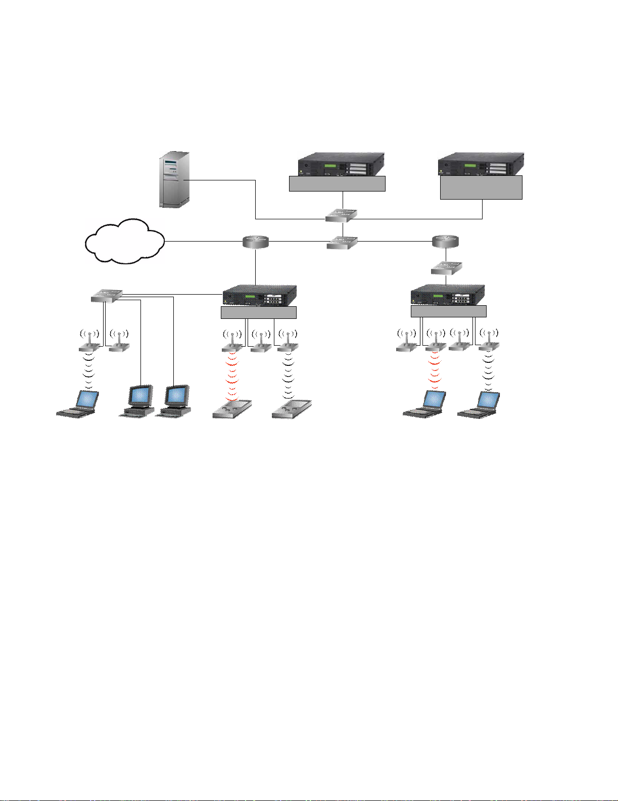
Figure 1-1 illustrates a 700wl Series system topology that is configured with redundant Access Control
Servers for failover.
Figure 1-1. 700wl Series topology
Access Control Server
Internet
Access Controller
Guest Employees Untrusted User Employee Untrusted User Employee
Redundant Access
Control Server
Access Controller
Access Controllers sit at or near the edge of the network, and enforce authentication and access policies.
As shown in
Figure 1-1, Access Points are typically connected directly to Access Controller ports, but it is
also possible to connect APs or clients through devices such as switches or hubs. When a client is detected
at an Access Controller port, the Access Controller must first determines who the client is based on the
Authentication Policy in force for that port at that time of day. The 700wl Series system supports a variety
of authentication methods, and can interface with an organization’s existing authentication services (such
as an LDAP service, RADIUS, Kerberos, 802.1x or NT Domain Logon) or can handle authentication
through its own built-in user database.
The Access Controller actually hands off the client authentication to the central Access Control Server,
which manages the authentication process and returns the appropriate Access Policy to the Access
Controller.
An Access Policy specifies the network addresses, services, and resources the client is permitted to access.
The Access Policy can also specify that client traffic for certain destinations be redirected to alternate
destinations. This capability is used by the 700wl Series system to redirect traffic from an unknown client
to a logon page. It can also be used to notify clients when they attempt to access non-permitted resources,
or to redirect a request to a permitted resource. Traffic to a destination that is neither permitted nor
redirected is dropped. An Access Policy may also specify other settings such as bandwidth limitations,
HTTP Proxy Servers (including filtering to impose HTTP access control), and encryption requirements.
Access Policies can be configured to “expire” after a specified length of time, or at a specific time, forcing
the client to reauthenticate.
1-2 HP ProCurve Secure Access 700wl Series Management and Configuration Guide
Page 17

Introduction
Clients that are successfully authenticated, Employees in Figure 1-1, are typically associated with Access
Policies that provide access to secure network resources. Clients that are not successfully authenticated,
Untrusted Users, are typically associated with an Access Policy that allows only the ability to logon. The
700wl Series system also provides a Guest logon feature and Access Policy, that can be used to provide
limited network access to users designated as Guests, for example, Internet access via the network with
no intranet access.
Access Policies are defined and maintained by the Access Control Server, but are administered by the
Access Controller. Once a client has been identified and the appropriate Access Policy has been returned
to the Access Controller, the Access Controller is responsible for filtering client traffic and either
forwarding it to its destination, redirecting it to the appropriate alternate destination, or dropping it. The
Access Control Server does not get involved again unless something occurs that requires a renewal of the
client’s rights, such as expiration of their existing rights, or roaming to a different location.
In addition to being the repository for the Authentication Policies, Access Policies, and other system
configuration information, the Access Control Server maintains status for every Access Controller. This
includes status for every client connected to the 700wl Series system and every client session.
700wl Series Functions
The 700wl Series system provides central control of Access Controllers, and clients. The key system
functions are: client authentication, rights management, Wireless Data Privacy, roaming support, NAT,
and VLANs.
Client Authentication
The 700wl Series system provides a great deal of flexibility in authenticating users. The system supports
three types of authentication:
• Browser-based logon: With browser-based logon, the first time a client attempts an HTTP access, the
Access Controller presents a browser-based logon page. After the user enters a logon ID and password,
the Rights Manager authenticates the client using one or more Authentication services, such as an
LDAP database, RADIUS server, Kerberos service, or through the Rights Manager’s own built-in
authentication database.
• VPN logon: With VPN logon, the client initiates a connection to the network using L2TP or PPTP. The
Access Controller uses the login information provided by the VPN client for authentication via
RADIUS or the built-in database. In this case, the user does not see the HP ProCurve logon page.
• Monitored logon: The 700wl Series system supports both 802.1x logon and NT Domain logon. In both
these cases, the system simply forwards the packets on to the RADIUS or NT Domain server, and
monitors the response to determine whether the client has been successfully authenticated.
Once the client has been authenticated, rights for the client are requested from the Rights Manager.
The Rights Manager uses the concept of Authentication Policies, which are ordered lists of one or more
authentication services. By defining multiple Authentication Policies, you can use different authentication
methods for users logging in through different locations or at different times.
The 700wl Series system supports the following authentication services, any of which can be used in an
Authentication Policy:
• LDAP directory services, such as Active Directory or iPlanet LDAP server
HP ProCurve Secure Access 700wl Series Management and Configuration Guide 1-3
Page 18

Introduction
• RADIUS servers
• Kerberos services
• XML-RPC-based services
• The Rights Manager’s built-in database. This is the default authentication service. You can populate it
with user names and passwords through the Rights Manager.
User Authentication is discussed in detail in Chapter 5, Configuring Authentication.
Client Access Rights
At any given time a certain set of rights is in effect for each client attached to an Access Controller. These
rights are based on a number of factors, including client authentication, client identity, location of the
connection, VLAN tags, and the time and day. The Rights Manager manages the criteria for each client
connection.
• The Rights Manager uses Access Policies to define what network resources a user can access at any given
time. Access Policies are defined for a group, and an individual user’s rights are determined by the
groups to which he or she belongs.
• The Rights Manager uses Identity Profiles and Connection Profiles to define which users can access the
network at any given time, what sorts of logon and authentication mechanisms may be used, and
what type of security is required.
• A client is matched to an Identity Profile based on who they are. They are matched to a Connection
Profile based on when and where they connect to the network. The Rights Manager uses the Identity
Profile and Connection Profile to match the client with the appropriate Access Policy. This in done in
the Rights Assignment Table.
Chapter 4, Configuring Rights describes this process in detail.
Wireless Data Privacy and VPN Protocols
The 700wl Series system’s VPN component enables strong encryption of data between a client and the
Access Controller. This provides additional security for data sent over the airwaves, replacing the
relatively insecure Wired Equivalent Privacy (WEP) of a wireless network.
The 700wl Series system offers four choices for encrypting data between a client and the Access
Controller: PPTP, L2TP/IPSec, tunnel mode IPSec, and SSH. It also supports a variety of authentication
and encryption algorithms related to these choices. It supports a number of client software packages that
handle the client side of the security method. In most cases, the 700wl Series system accepts the
authentication performed by the security protocol and provides user access rights as soon as the secure
connection has been set up.
Once a secure connection has been set up, clients can roam between access points and the 700wl Series
system will maintain each session transparently to the client.
Roaming Support
One of the key features of the 700wl Series system is its support of layer 3 roaming—enabling clients to
move around physically between access points without having to reauthenticate or establish a new
session.
1-4 HP ProCurve Secure Access 700wl Series Management and Configuration Guide
Page 19

Introduction
Because the 700wl Series system identifies clients by MAC address, it is simple to detect when a device
roams. A Linger Timeout determines the length of time a client has to complete a roam, that is to appear at
a new physical location after disappearing from the old physical location. The settings for timing out a
roaming client are part of the client’s assigned Access Policy; different clients can have different settings
and one client can have different settings depending on their location, time of day, and so on.
If the client completes the roam within the linger time, no reconnect or authentication is needed—the
client’s connection state is maintained intact. If the client fails to complete the roam before the linger
timer expires the 700wl Series system concludes the client has actually disconnected and logs the client
off.
Roaming support is discussed in more detail in VLANs and the 700wl Series System in Chapter 2, Using the
700wl Series System.
Network Address Translation
By default, an Access Controller provides Network Address Translation (NAT) services for clients that
request a DHCP IP address when they initiate a connection to the Access Controller. The 700wl Series
system implements NAT as a form of “overloading,” where a range of private IP addresses are mapped
to a single public IP address (the IP address of the Access Controller) by using TCP ports. When a client
sends a packet through the Access Controller, the Access Controller rewrites the IP address field and the
port number field to a value that is unique within the entire 700wl Series system and uses this unique
identifier for returned packets.
Although NAT is enabled by default in the 700wl Series system you can elect whether to use it or not
depending on your application. Following are some points in favor of using NAT within the 700wl Series
system:
• NAT makes roaming much more efficient. Because each NAT address is unique for the entire 700wl
Series system, the client’s connection state can be moved to the nearest Access Controller while
roaming, rather than requiring every connection to be tunneled back to the original Access Controller.
• NAT provides some amount of protection to a client since no device other than an Access Controller
can talk directly to the client. This provides rudimentary firewall protection.
• Allowing NAT can ensure that a client will be able to successfully communicate with the network—if
NAT is not allowed, and a client has an IP address that is not within the subnet used by the Access
Controller, return packets will not be able to reach the client. A client having an IP address not within
the Access Controller’s subnet can occur if the client uses a static IP address or receives an IP address
from an external DHCP server.
However, certain applications may require a host or server system to know the actual IP address of a
client. Some examples include multi-player games, file transfer in Instant Messenger applications, and
other peer-to-peer applications.
To allow flexibility, the 700wl Series system provides alternate addressing schemes:
• Use NAT only if the client’s IP address is on the wrong subnet, that is specifically not within the Access
Controller’s subnet. Otherwise, use the client’s real or static IP address.
• Always use the client’s real or static IP address and never use NAT, regardless of the subnet. This
setting is intended for access points, and should be used with caution.
There is one case where NAT will always be used—when PPTP/L2TP tunneling is used.
HP ProCurve Secure Access 700wl Series Management and Configuration Guide 1-5
Page 20

Introduction
Addressing in the 700wl Series System in Chapter 2, and Chapter 4, Configuring Rights include more
extensive discussions of addressing considerations and NAT.
VLAN Tag Support
The HP System provides support for Virtual LAN (VLAN) tagging in several ways:
• A client can be matched to a Connection Profile based on the VLAN ID (802.1Q tag) associated with the
client traffic.
• The VLAN tag associate with the client traffic can be stripped, added, or rewritten before the traffic is
forwarded onto the network, based on the Access Policy in force for the client.
Matching a client to a Connection Profile based on the VLAN tag effectively enables you to assign an
Access Policy to clients in a specific VLAN. The Access Policies associated with the VLAN-specific
Connection Profiles can be configured to modify the VLAN tagging of these clients, if necessary. By
default, the tag associated with the client’s traffic is removed so the client’s traffic is sent on to the
network untagged. This scenario can be useful if you want to use the client’s VLAN membership only to
assign access rights for the client, and once the Access Policy is in place, the VLAN tag is no longer used.
Optionally you can configure the Access Policy to preserve the tag or you can replace the original tag
with a different tag.
The 700wl Series system also provides limited support for assigning IP addresses through DHCP based
on the VLAN tag of the incoming traffic. In the 700wl Series system, IP subnet ranges may be specified on
a port-by-port basis. In order to restrict an IP range to members of a specific VLAN, you can associate a
Connection Profile that filters for the desired VLAN with the port that defines the subnet range.
1-6 HP ProCurve Secure Access 700wl Series Management and Configuration Guide
Page 21

2
USING THE 700WL SERIES SYSTEM
This chapter provides a brief introduction to using the 700wl Series system and its Administrative
Console. It also provides an overview and discussion of a number of common tasks you may need to
accomplish. The topics covered in this chapter include:
Initial Configuration of the 700wl Series System . . . . . . . . . . . . . . . . . . . . . . . . . . . . . . . . . 2-1
Managing and Administering the 700wl Series System . . . . . . . . . . . . . . . . . . . . . . . . . . . 2-2
Logging on to the Administrative Console . . . . . . . . . . . . . . . . . . . . . . . . . . . . . . . . . . . . . . 2-4
Using the Administrative Console . . . . . . . . . . . . . . . . . . . . . . . . . . . . . . . . . . . . . . . . . . . . . 2-7
Basic System Configuration Tasks . . . . . . . . . . . . . . . . . . . . . . . . . . . . . . . . . . . . . . . . . . . . 2-16
System Features and Concepts . . . . . . . . . . . . . . . . . . . . . . . . . . . . . . . . . . . . . . . . . . . . . . . 2-17
This chapter assumes that you have installed your HP ProCurve Access Control Server or Integrated
Access Manager as instructed in the 700wl Series Quick Start Guide or the 700wl Series Installation and
Getting Started Guide. This chapter takes you through the next steps towards configuring and using the
700wl Series system. The first section takes you through the required settings from the “Complete the
Configuration” steps in the 700wl Series System Quick Start Guide.
This chapter assumes you are new to the 700wl Series system. For users who are upgrading their 700wl
Series system from a previous software version to version 4.1, you should read the 700wl Series
Introduction to Software Version 4.x. The Introduction to Software Version 4.x document introduces you to
software version 4.0 as part of the process of migrating your system, and explains what has changed from
versions 3.0 and 3.1.
Initial Configuration of the 700wl Series System
The initial configuration of a 700wl Series system component, sufficient to allow network access, is
described in both the 700wl Series Quick Start Guide shipped with each hardware unit, and in more detail
in the 700wl Series Installation and Getting Started Guide.
If you have installed your 700wl Series system according to the instructions in the Quick Start Guide, it
should be configured with a set of basic network configuration settings.
For an Access Control Server, these settings include:
• An IP address of the Access Control Server
• Subnet mask that defines the subnet associated with the Access Control Server (the default is
255.255.255.0 (/24))
• Name of the domain in which the 700wl Series system resides
• Default router (gateway) IP address
2-1
Page 22

Using the 700wl Series System
• Primary and secondary DNS server addresses
• Shared secret, used to enable Access Controllers or a peer Access Control Server to establish a trusted
communication relationship with the Access Control Server. This is actually an optional item in the
initial installation process of an Access Control Server, but no system components will be able to
communicate with the 700wl Series system until this is set, so it is recommended that you do it as part
of the initial installation.
For an Access Controller, the initial settings include:
• IP address of the Access Controller
• Subnet mask that defines the subnet associated with the Access Controller (the default is
255.255.255.0 (/24))
• Domain name
• Default router (gateway) IP address
• Primary and secondary DNS server addresses
• IP address of the Access Control Server that will manage the Access Controller
• Shared secret of the Access Control Server
If you allow your 700wl Series system components to get their IP address from a DHCP server, the
DHCP server can provide the domain, default router IP address, DNS addresses, and WINS addresses.
On a newly-installed or Factory Reset Access Control Server, the following defaults are in effect:
• The DHCP address range for use with NAT’ed clients is the 42.0.0.0 subnet
• An HP ProCurve-signed SSL certificate is in place
• SNMP is disabled
• Wireless Data Privacy settings (encryption protocols) are disabled
• The default Authentication Policy uses the built-in database for user authentication
Managing and Administering the 700wl Series System
A 700wl Series system consists of an HP ProCurve Access Control Server and one or more HP ProCurve
Access Controllers, or an HP ProCurve Integrated Access Manager, optionally with additional Access
Controllers connected. All the elements of your 700wl Series system are configured, monitored and
managed centrally from the Access Control Server or Integrated Access Manager. This monitoring and
management is done through the Administrative Console, a web-browser-based interface that runs on the
Access Control Server or Integrated Access Manager.
Note: An HP ProCurve Integrated Access Manager is effectively an Access Control Server and an
Access Controller physically integrated into a single module. However, the 700wl Series system
software internally handles the functions within an Integrated Access Manager as if they are two
separate subsystems. Therefore, throughout this guide, system features are described in terms of
Access Control Servers and Access Controllers. These features all apply to an Integrated Access
Manager as well.
2-2 HP ProCurve Secure Access 700wl Series Management and Configuration Guide
Page 23

Using the 700wl Series System
The 700wl Series system provides three levels of administrator access:
• A Network Administrator can configure the network parameters that enable the 700wl Series system
to function in a network, such as configuring IP addressing, interface configuration, date and time
settings, SNMP access, and performing software updates and backups. The network administrator
can perform these functions for all system components that make up a 700wl Series system. A
Network Administrator cannot perform any functions under the Rights Manager, such as adding
users, creating or modifying Access Policies, modifying the Rights Table, setting up Authentication
Services or Authentication Policies, or other similar functions. A Network Administrator can view
all the pages in the Status and Logs areas.
• A
Policy Administrator
removing users, configuring Authentication, setting up Identity Profiles, Connection Profiles, and
Access Policies, and manipulating the Rights Assignment Table. A Policy Administrator cannot
modify any of the network configuration parameters, or perform system software updates, backups,
or restarts. A Policy Administrator can view all the pages in the Status and Logs areas.
• A
Super Administrator
a 700wl Series system—both network and rights configuration. In addition, a Super Administrator
can add, delete, enable, and disable other administrator.
There is one built-in administrator that has Super Administrator capabilities. This is the only
administrator that exists on a new unit. While all other administrator settings are maintained in the
700wl Series system database, and thus are deleted if the system is reset to factory defaults, the
built-in administrator simply has its name and password reset to the default.
The built-in administrator name and password can be changed on the System Components Edit
page for an individual system component. For information about creating additional administrator
accounts, see
Setting Up Administrators on page 6-42.
can perform functions under the Rights Manager, such as adding and
can perform all the administrative functions for all connected components of
Centralized Administration
Wireless network clients connect through an Access Controller, but authentication and rights
administration for these clients is handled centrally from the Access Control Server. In addition, all
configuration of the Access Control Server and all Access Controllers connected to the 700wl Series
system is handled through the Administrative Console running on the Access Control Server. Once you
have installed an Access Controller onto your network following the instructions in the 700wl Series Quick
Start Guide, all other administration on the Access Controller is handled through the Access Control
Server.
From the centralized Administrative Console on your Access Control Server you can perform the
following functions:
• Monitor in real-time the status of all the 700wl Series system components
• Monitor in real-time the status of all clients logged onto the system, and monitor the status of all their
sessions
• View the 700wl Series system logs
• Update access rights for clients in real-time
• Log clients out of the system
• Configure advanced network settings for 700wl Series system components, including bridging, DHCP
addressing for use with NAT, IP broadcast forwarding, setting up HTTP proxies, configuring SNMP
settings, and setting the system date and time
HP ProCurve Secure Access 700wl Series Management and Configuration Guide 2-3
Page 24

Using the 700wl Series System
• Enable or disable Wireless Data Privacy protocols, configuring the address method and range for VPN
tunneling, and configuring IPSec parameters
• Update the 700wl Series system software
• Back up a 700wl Series system component’s configuration, and restore the backup if needed
• Set up Connection Profiles that identify where and when clients connect to the 700wl Series system
• Set up Authentication Policies that determine how clients authenticate themselves to the system
• Set up Access Policies to control what users can do over the network
• Set up Identity Profiles to put users in groups that share the same access policies
• Customize login pages
Logging on to the Administrative Console
To monitor or configure the 700wl Series system you use the Administrative Console. This is a web-based
interface. To log in to the Administration Interface over the network, follow these steps:
Step 1. Set your browser to the IP address or hostname of your Integrated Access Manager or Access
Control Server.
For example, if the IP address of your Access Control Server is 10.2.3.4, you can access its
Administrative Console by entering
browser software.
http://10.2.3.4 in the address or location textbox of the
The Administrator Logon page appears, as shown in Figure 2-1.
Note: Your browser must accept cookies to enable logging on.
Step 2. Enter your administrator name and password and click Logon.
The initial administrator name is “admin” and the initial password is “admin.”
Figure 2-1. Administrator Logon Page
The Administrative Console initially displays the Equipment Status tab under the Status module.
2-4 HP ProCurve Secure Access 700wl Series Management and Configuration Guide
Page 25

Using the 700wl Series System
Note: It is strongly recommended that you change the built-in administrator logon name and password
as soon as possible. You should also set the date and time for each 700wl Series system component
(Access Control Server, Integrated Access Manager, and Access Controllers).
Changing the Built-In Administrator Username and Password
To change the built-in administrator name and password on a 700wl Series system unit do the following:
Step 1. Click the Network button in the Navigation bar. The System Components page appears, with a
System Components list that shows the components that make up your 700wl Series system.
Step 2. Click a system component name listed under the Component Name heading to bring up the
Edit page.
Step 3. In the Admin Username field, type a new administrator user name.
Type a new password in the
Password
Step 4. Click Save.
field.
Admin Password field, and type it again in the Confirm Admin
You can make other changes on this Edit page, such as giving the unit a descriptive name, changing the
shared secret, and so on. See Configuring an Access Control Server on page 6-3, Configuring an Integrated
Access Manager on page 6-7, or Configuring Access Controllers on page 6-10 in Chapter 6 for more
information on changing these settings.
Note:
logon name and password are also reset to their defaults.
When a 700wl Series system unit is reset to its factory default settings, the built-in administrator
The built-in administrator for an Access Control Server or Integrated Access Manager has the
equivalent of Super Administrator capabilities—this administrator can configure all network and
Rights settings for the Access Control Server or Integrated Access Manager as well as perform
configuration through the Administrative Console for any Access Controllers connected to the Access
Control Server or Integrated Access Manager. The built-in administrator for an Access Controller can
only log on to that Access Controller through the Command Line Interface (CLI).
You can create additional 700wl Series system administrators on the Access Control Server or Integrated
Access Manager, with different administration roles—Super Administrators, Network Administrators,
and Policy Administrators. See
Setting Up Administrators on page 6-42 for information about creating
additional administrators.
Using Online Help
The 700wl Series system offers several levels of Help:
• Each page of the Administrative Console includes some basic Help, normally displayed in the left panel
under the page name (and beneath the System Components List or page links, if they are present on
the pa
ge).
• The Help button displays context-sensitive help presented in a separate browser window. The
contents of this page are different depending on the page of the Administrative Console you are
viewing when you click Help. Once inside the help system you can move around to view different
topics using a variety of navigation tools:
— Next/previous page buttons
HP ProCurve Secure Access 700wl Series Management and Configuration Guide 2-5
Page 26

Using the 700wl Series System
— Links within the page contents
—
Related Topics links: these are presented at the top of the page, or they can be accessed from a
Related Topics menu displayed using the Related Topics button
— Table of Contents and Index, accessed through the navigation panel at the left of the page.
— You can display the Table of Contents by clicking the Contents button
You can also print the page you are viewing by clicking the print button .
• From the Help window, you can display the full 700wl Series system Management and Configuration
Guide by clicking the PDF button (
This requires a version of Adobe’s Acrobat Reader software, which is available free of charge from
Adobe Systems at http://www.adobe.com.
).
Logging Out
To log out of the Administrative Console:
» From any page, click the Logout button at the right of the Navigation bar. See Figure 2-2.
Figure 2-2. Logging Out
2-6 HP ProCurve Secure Access 700wl Series Management and Configuration Guide
Page 27

Using the 700wl Series System
Using the Administrative Console
When you first logon to the Administrative Console, your browser displays the Equipment Status tab of
the Status pages (Figure 2-3).
Figure 2-3. Initial Page of the Administrative Console
.
Header Bar
Navigation Bar
Tabs
Page Title
Left Panel
Sub-Tab
Main
Panel
The various pages of the Administrative Console have many elements in common, as well as elements
specific to certain pages.
All pages have the following elements in common:
• The Header bar—Administrative Console session information
• The Navigation bar—Navigation and Logout buttons
• Tabs—Main function pages under each Navigation button containing left and main panels
• Left Panel—Instructive page information, page and component links, and data filters
• Main Panel—Input interfaces in the form of tables or sub-tabs, and tables displaying logs or status
Header Bar and Navigation Bar
The Header bar identifies the Access Control Server on which you are running the Administrative
Console. The Navigation bar shows the top-level set of options provided by the Administrative Console
based on the type of access the logged-in Administrator is permitted.
Navigation bars of a single Access Control Server for an administrator with Super Admin access.
HP ProCurve Secure Access 700wl Series Management and Configuration Guide 2-7
Figure 2-4 shows the Header and
Page 28

Using the 700wl Series System
Figure 2-4. Header and Navigation Bars for an Access Control Server
Information at the right side of the Header bar shows the username of the logged in Administrator, the
IP address of the Access Control Server, and the current date and time.
• If the IP address is labeled simply Access Control Server, this Access Control Server is functioning
as the only Access Control Server in the 700wl Series system. If the system is an Integrated Access
Manager, the label will reflect that.
• If the IP address is labeled Primary Access Control Server, this Access Control Server is currently
functioning as the primary Access Control Server in a redundant configuration. You can perform all
management and configuration functions for your 700wl Series system from this Access Control
Server.
• If the IP address is labeled Secondary Access Control Server, this Access Control Server is
functioning as a secondary Access Control Server in a redundant configuration. In this case, the
Header bar is also labeled with a large “secondary” and only a subset of the Navigation buttons are
available. (see
Secondary Access Control Server.
Figure 2-5). Limited configuration capabilities are available directly through the
Figure 2-5. Header and Navigation Bars for a Secondary Access Control Server
The Navigation bar is always accessible from anywhere in the Administrative Console. Each Navigation
button takes you to a set of pages related to specific administrative functions.
Status
The Status pages of the Administrative Console provide views of the status of system equipment,
clients, and sessions. The Equipment Status tab is displayed when a 700wl Series system
administrator first enters the Administrative Console. These pages are available to administrators
of all access levels.
For details, refer to Chapter 3, System Status.
Rights
The Rights Manager pages of the Administrative Console enable you to manage access rights for
clients, customize client logon windows, and configure authentication and access control policies.
These pages are available to Super Administrators and Policy Administrators. Additional tools
such as simulating user rights for testing are also available.
2-8 HP ProCurve Secure Access 700wl Series Management and Configuration Guide
Page 29

Using the 700wl Series System
For details, refer to Chapter 4, Configuring Rights and Chapter 5, Configuring Authentication.
Network
The Network pages enable configuration of the 700wl Series system components to work with
your enterprise network. Most pages in this area are available to Super Administrators and
Network Administrators only. However, both Network Administrator and Policy Administrators
can change their own passwords under this function.
For details, refer to Chapter 6, Configuring the Network.
VPN
The VPN pages enable Wireless Data Privacy configuration, such as configuring IPSec,
certificates, and IP address assignment for tunneling. These pages are available to administrators
of all access levels.
For details, refer to Chapter 7, Setting up Wireless Data Privacy.
Maintenance
The Maintenance pages provide the following functions: Software Setup, Backup & Restore, and
Shutdown/Restart of 700wl Series system equipment. These pages are available to Super
Administrators and Network Administrators.
For details, refer to Chapter 8, System Maintenance.
Logs
The Logs pages provide views of the log data, which includes time, source, severity and event
description. Log data can be filtered and exported as text files. Configure the settings for a syslog
server. These pages are available to administrators of all access levels.
For details, refer to Chapter 9, Logs.
Help
Click this button in the Navigation bar to view context-sensitive HTML help for the tab or
subordinate tab displayed. You can also access the complete 700wl Series system Management and
Configuration Guide in PDF format from the Help interface.
Logout
Click this button to log out of the 700wl Series system. A new logon window is displayed. You will
need to log on again to perform additional system tasks with the Administrative Console.
Summary of Functions
The main administrative functions and the first level of tabs available under each Navigation button
are listed below.
HP ProCurve Secure Access 700wl Series Management and Configuration Guide 2-9
Page 30

Using the 700wl Series System
.
Status Rights Network VPN Maintenance Logs
• Equipment • Rights Setup • System • Wireless Data • Software Setup • Log Files
Status Components Privacy Setup
• Client Status • Identity Profiles • Network Setup • Certificates • Backup & • Logging Setup
Restore
• Session Status • Connection • Interfaces • IP Address • Shutdown/
Profiles Assignment Restart
(for Tunneling)
• License • Authentication • SNMP
Information Policies
• Access Policies • Date & Time
• Login • Admin Setup
Customization
• Tools & Options
Tabs
Tabs are used to access the pages found under a Navigation button. Clicking a button on the Navigation
bar displays the first (left-most) tab for that set of functions, as shown in Figure 2-3. The active tab is
shown in white. Clicking an inactive tab makes it the active tab and displays the page for that subset of
functions.
Some tabs represent complex sets of functions. These may use sub-tabs to further organize the functions
and make them easier to use. Sub-tabs work the same as tabs, with the active tab shown in white and
inactive tabs grayed out.
When there are action buttons, for example, the
the page, the buttons pertain to the entire set of functions available under the tab. When the action
buttons are displayed within the grayed area under a sub-tab, the buttons apply only to the input fields
for the sub-tab.
A main tab page is divided into two distinct areas—the left panel containing informational and
navigational aids, and the main panel containing the main functional area of the page (see
Function-specific elements that are common to many pages include:
• System Component list, Navigation links, or Display filters
• Input interfaces such as text fields, check boxes, buttons, drop-down lists
• Table manipulation buttons for re-ordering, editing, or deleting rows
• Page navigation controls for viewing large amounts of data spanning multiple pages
• Refresh mechanisms for updating the page, and Save, Save As Copy, Reset to Defaults, and Cancel
buttons
Save button ( ), displayed at the bottom of
Figure 2-3).
2-10 HP ProCurve Secure Access 700wl Series Management and Configuration Guide
Page 31

Using the 700wl Series System
Left Panel
The left panel contains explanatory or descriptive text about the page and its functions. It also contains
controls for the features of the page, and navigation aids. The specific controls in the left panel depend
on the function of the page. The left panel may contain one of the following function-specific elements:
• System Component list
• Navigation links
• Display filters
System Components List
On pages where you need to apply commands to specific HP ProCurve components (Access Control
Server, Integrated Access Manager or Access Controller) a concise version of the System Components
list appears in the left panel. To configure or maintain a specific component, click the component name
in the System Components list to select it. The selected component appears highlighted and the page
changes to display the current settings for that component. Any changes you make apply to that
component.
The folders in the System Components list can be opened and closed to display the components that
comprise the 700wl Series system.
Figure 2-6 shows an example of a System Components list.
Figure 2-6. System Components List
Note: In a redundant configuration, both Access Control Servers are shown in the System
Components list. However, you cannot make configuration changes to the secondary Access Control
Server from the Administrative Console on the primary Access Control Server, and vice versa. You
must logon to the Administrative Console of the peer Access Control Server to make changes to it.
Navigation Links
On some pages you can toggle among different related functions or views of the system data by
clicking one of the links available in the left panel. The active navigation link is grayed out in the list, as
shown in
Figure 2-7. Navigation Links
Figure 2-7.
Navigation Links
HP ProCurve Secure Access 700wl Series Management and Configuration Guide 2-11
Page 32

Using the 700wl Series System
Display Filters and Auto Refresh Settings
Some data, such as the contents of the log, can be very lengthy. To control the display of such information
you can use filters to selectively display subsets of the total information.
Figure 2-8. Display Filters and Auto Refresh Settings
Display
Filter
Options
Select the desired filter values using the drop-down lists and click Apply Filters to refresh the
display with data that matches the filter criteria. On the Log Files page, a Search capability is also
provided to allow you to search for a particular string in a log file message. See
Figure 2-8. On
pages that display dynamic data you can set the page to automatically refresh the data at specified
intervals using the Auto Refresh option.
Main Panel
The main panel under a tab can show two basic types of displays:
• A list or table that gives a summary view of the main elements under a tab, and may provide further
navigation to view details about or manage those elements
• A set of fields, checkboxes, or buttons for configuring a particular entity of the 700wl Series system.
2-12 HP ProCurve Secure Access 700wl Series Management and Configuration Guide
Page 33

Using the 700wl Series System
Tables
In configure tables, each row in a table typically displays the key items that define the element
represented by the table row. For example, rows in the Rights Assignment table show the Identity
Profile, Connection Profile, and Access Policy that defines the Rights Assignment row.
Configure tables, primarily those under the Rights tabs, provide the ability to edit the row
definitions, add or delete rows, and edit or configure individual items within a row. Data tables,
such as those under Status, provide the ability to view more detailed information about rows in the
table or items within a row, but not alter the contents of the rows themselves.
Figure 2-9. Configure Tables
• Manipulating rows
To operate on rows in a table, use the buttons on the right side of the row as shown in Figure 2-9.
The common buttons for editing a row (
) and for deleting an row ( )are shown. See Common
Buttons on page 2-15 for a full list of buttons.
• Manipulating items within a row
In some tables you can edit an item in the table by clicking on that item. Row items that can be
edited or configured appear as a link when the cursor is rolled over the item. An example of this is
show in
Figure 2-9 where the “Manufacturing” link under the Connection Profile column is
highlighted.
HP ProCurve Secure Access 700wl Series Management and Configuration Guide 2-13
Page 34

Using the 700wl Series System
Figure 2-10. Data Tables
Sortable column
• Sortable Column Headings
In some tables you can sort the items in the table based on the table columns. Column headings
that allow sorting appear as a link when the cursor is rolled over the column name, as shown in
Figure 2-10. In some tables, such as the Log Files display, where there are multiple headings shown
in a column, you can sort on each item in the column separately. This is the case with the example
in
Figure 2-10).
Clicking the column heading sorts the table based on the alphabetical ordering of the items in that
column. Clicking the first time sorts in ascending order; clicking a second time reverses the sort
order. The column that is currently determining the display order is indicated by showing the
heading cell in a darker grey. In
Figure 2-10 the display is ordered based on the
Time column.
• Page Navigation Controls
If a table contains more than 25 rows, the table is displayed in multiple pages with 25 rows per
page. You can change the number of lines displayed per page using the filter settings discussed
earlier. A set of page navigation controls are displayed below the bottom right corner of the table.
You can navigate among the pages in two ways:
— Use the forward ( ) and backward ( ) arrow buttons to view pages sequentially.
Buttons are grayed out if you cannot move in that direction.
— Select a page number from the drop-down list (
Figure 2-11. Page Navigation Controls
) to go directly to a specific page.
Page Navigation Controls
2-14 HP ProCurve Secure Access 700wl Series Management and Configuration Guide
Page 35

Using the 700wl Series System
Common Buttons
The following table lists the common buttons used in the Administrative Console and gives their
meaning.
Table 2-1. Administrative Console Buttons
Button Function
Folder: This represents a user-defined folder for system components. Folders can be opened, revealing their
contents, by clicking on the open folder button
(). This button appears in the System Components List. See the example in Figure 2-6.
Edit: Click this button to edit the object in the same row. If the item cannot be edited, the button is dimmed.
See Figure 2-9 for an example of this button.
Remove: Click this button to delete the object in the same row. If the object in the row cannot be deleted, the
button is dimmed. See Figure 2-9 for an example of this button.
ReOrder: Click the up or down arrows to move the row up or down in the table. If the row is at the top or
bottom of the table, only one arrow is enabled. If a particular row cannot be moved, the button is dimmed.
See Figure 2-9 for an example of this icon.
View: Click this button to view supporting information about a particular function. This button appears in the
New/Edit Filter pages for Allowed and Redirected Traffic Filters.
(). They can be closed by clicking on the close folder button
Refresh Rights: Click this button to update the rights for the client in the same row. This button appears in
the Client Status table.
Logout: Click this button to logout the client in the same row. This button appears in the Client Status table.
HP ProCurve Secure Access 700wl Series Management and Configuration Guide 2-15
Page 36

Using the 700wl Series System
Basic System Configuration Tasks
When you have completed the installation of your 700wl Series system following the instructions in the
700wl Series system Quick Start Guide or the 700wl Series system Installation and Getting Started Guide for the
components in your system, there are still some basic configuration tasks you may need to perform.
• If you have not done so already, change your administrator logon username and password. See
Changing the Built-In Administrator Username and Password on page 2-5.
• To add users to the system and specify what access rights they should have, read Chapter 4,
Configuring Rights.
• To specify one or more external authentication services, LDAP, RADIUS, Kerberos or XML-RPC,
802.1x or NT Domain logon, for user authentication, read Chapter 5, Configuring Authentication.
• To specify access policies that define permitted access for users, read Chapter 4, Configuring Rights.
• To enable and configure the 700wl Series system to allow access using VPN protocols, read Chapter 7,
Setting up Wireless Data Privacy.
• Once the 700wl Series system is up and running, and you want to monitor system and client status
you should read Chapter 3, System Status.
• When you are ready to back up your 700wl Series system configuration, read Backing Up and Restoring
the System Configuration in Chapter 8, System Maintenance.
• If you want to upgrade the 700wl Series system software, read Updating the System Software in
Chapter 8, System Maintenance.
Setting Up Authentication and Access Rights
Chapter 4, Configuring Rights and Chapter 5, Configuring Authentication together explain the Rights
Manager and should be read together since access rights and authentication are closely related.
To do the following:
Add users to the built-in database for user authentication
Add the MAC addresses of APs or other network devices
Create an Identity Profile
Configure an authentication service
Define an Authentication Policy
Define a Location
Define a Time Window
Create a Connection Profile
Define or modify an Access Policy
Add an entry to the Rights Assignment Table
Go to:
Creating or Editing a User on page 4-17
Creating or Editing an Equipment Entry on page 4-22
Creating or Editing an Identity Profile on page 4-13
Configuring Authentication Services on page 5-7
Creating or Editing an Authentication Policy on page 5-6
Locations on page 4-35
Time Windows on page 4-37
Creating or Editing a Connection Profile on page 4-31
Creating or Editing an Access Policy on page 4-43
The Rights Assignment Table on page 4-6
Customize the Logon page
Customize the Stop page
2-16 HP ProCurve Secure Access 700wl Series Management and Configuration Guide
Customizing a Logon Page on page 5-32
Customizing the Stop Page on page 5-37
Page 37

Using the 700wl Series System
System Features and Concepts
The following sections provide an introduction to some of the key concepts and functions that are
central to the 700wl Series system. Many of these concepts are discussed in more detail in the
appropriate chapters later in this Guide. However, some of the discussions below do require an
understanding of other concepts such as how Access Rights are defined and administered in the 700wl
Series system.
Centralized Management and Administration
All configuration, management, and monitoring of the components of the 700wl Series system, with
very few exceptions, are done through the centralized Administrative Console, accessed through the
Access Control Server. The Access Control Server maintains the status and configuration information
for the Access Controllers it serves. When changes are made to an Access Controller configuration, the
change is saved on the Access Control Server as well as being propagated to the Access Controller.
The only configuration that should be performed directly on an Access Controller is setting the initial
network configuration when the unit is first installed on your network. This is necessary to enable the
Access Controller to communicate with the Access Control Server, and should be performed through
the CLI.
As soon as an Access Controller is configured to communicate with its Access Control Server, that
Access Controller will appear in the System Components list on the Access Control Server. By selecting
the Access Controller in this list you can perform configuration and management functions such as
setting the date and time, configuring options such as bridging, port subnets, SNMP access, and so on.
You can also initiate upgrades, and shut down or restart the unit through the centralized interface.
System-wide backups are performed from the central Administrative Console. In addition, status
information such as client and session status, is gathered from the Access Controllers and is maintained
and displayed centrally. Log entries are also stored centrally rather than on each Access Controller.
Because configuration information for an Access Controller is maintained by the Access Control Server,
configuration changes must not be made directly on an Access Controller. Changes made directly on the
Access Controller are not reflected in the central database, and those changes would be overwritten the
next time the Access Control Server propagated configuration information to the Access Controller.
In earlier versions of the 700wl Series system, it was possible to access an Administrative Console on
an Access Controller by pointing a web browser to the IP address of the Access Controller. This is no
longer supported—instead the Access Controller just displays a page with a link to the Access Control
Server Administrative Console, as shown in
Figure 2-12.
HP ProCurve Secure Access 700wl Series Management and Configuration Guide 2-17
Page 38

Using the 700wl Series System
Figure 2-12. Access Controller Redirect Page
Enterprise Class Redundancy
The 700wl Series system supports Access Control Server redundancy and failover. Access Control
Server failover provides high availability operation for clients in case of system outages, network
failures, or other disruptions. The primary Access Control Server functions as a normal Access Control
Server, servicing the connected Access Controllers’ requests for authentication, rights administration,
and other functions. The redundant Access Control Server is synchronized with the primary Access
Control Server through a combination of database replication, message and state replication, and
configuration replication, and is kept synchronized via incremental SQL updates.
To set up a redundant Access Control Server, the following is required:
• Two peer Access Control Servers, each running version 4.0 or later software, must exist on the
network and be mutually reachable. Integrated Access Managers cannot be used as redundant
peers.
• One of these Access Control Servers must have the
checked as part of the Access Control Server setup under the System Components tab of the
Network pages. Only one of the peer Access Control Servers may have this option checked.
• Both Access Control Servers, and all Access Controllers, must be configured with the same shared
secret in order to communicate with each other.
• As Access Controllers are installed on the network, they are configured with the IP address of the
Preferred Primary Access Control Server. Access Controllers in a system with redundant Access
Control Servers receive the address of the secondary Access Control Server from the Primary Access
Control Server.
See Configuring Failover with Redundant Access Control Servers on page 6-15 in Chapter 6 for details on
configuring redundant Access Control Servers.
Preferred Primary Access Control Server option
How Access Control Server Failover Works
When a redundant relationship is established, the primary Access Control Server initially replicates its
configuration state and database on the secondary Access Control Server. From then on, SQL updates
will keep the secondary Access Control Server synchronized with the primary Access Control Server. A
“heartbeat” message between the primary and secondary is used to keep the secondary Access Control
Server informed that the primary is functioning.
2-18 HP ProCurve Secure Access 700wl Series Management and Configuration Guide
Page 39

Using the 700wl Series System
The communication between the two peer Access Control Servers is done via a proprietary message
based protocol over TCP/IP.
Upon restart, an Access Controller attempts to communicate with the primary Access Control Server. If
that fails, the Access Controller attempts to communicate with the secondary Access Control Server.
In the event of a primary Access Control Server failure, or failure on the network segment on which it
resides, the secondary Access Control Server will fail to receive the heartbeat message. A failover
timeout is used to determine when it is appropriate for the secondary Access Control Server to take over
management of the 700wl Series system. Depending on the nature of the failure, this may work in one
of several ways:
• If the primary Access Control Server has actually failed or gone offline, the Access Controllers it
was administering will no longer be able to contact it. They will then attempt to establish
communication with the secondary Access Control Server. This Access Control Server will become
the primary Access Control Server, and the failed Access Control Server, when it comes back online,
will be the secondary Access Control Server.
• If the loss of heartbeat is due to a failure or disruption of the network between the two Access Control
Servers rather than a failure of the primary Access Control Server itself, the Access Controllers that
reside in the same partition as the primary Access Control Server will continue to communicate
successfully with that Access Control Server. Access Controllers in the other network partition will
establish connections with the secondary Access Control Server, which will become the primary
Access Control Server to those Access Controllers.
When an Access Control Server failover occurs, authenticated clients on the various Access Controllers
will continue to have access to the network and will not be aware of the failover.
Access Control Server failover to the secondary Access Control Server is automatic. Return of control to
the primary Access Control Server is a manual process. This allows the system administrator time to
diagnose and repair the network failure or problem with the primary Access Control Server before
returning control. Once the primary Access Control Server is back on-line the two Access Control
Servers automatically synchronize their data. The system administrator can manually return control to
the original primary Access Control Server by restarting the new primary Access Control Server
(originally the secondary) to force a fail-back to the original (Preferred Primary) Access Control Server.
This is done through the Shutdown/Restart tab under the Maint navigation button.
The overall time required for a failover to occur is a function of several factors:
• The time interval specified in the Failover Timeout field in the Edit Control Server page
• The latency in the network link between the primary and the secondary Access Control Servers
If the primary and secondary Access Control Servers are located together with a hardwired link between
them, the overall failover time can be as small as one second. If they are located thousands of miles apart
then the latency time for communication between the two Access Control Servers may become
significant.
Avoiding Configuration Data Loss in a Redundant System
When setting up a redundant configuration for Access Control Server failover, there are a few situations
where it is possible to experience the loss of some configuration data.
The first situation is if you designate an Access Control Server as secondary when it still has valid
configuration data. For example, if it is actively managing an Access Controller with connected clients,
HP ProCurve Secure Access 700wl Series Management and Configuration Guide 2-19
Page 40

Using the 700wl Series System
or has some other configuration information you would prefer not to lose. The act of making it a
secondary Access Control Server in an active redundant peer relationship will cause its configuration to
be overwritten by the Primary Access Control Server configuration. This situation can be avoided by
backing up the configuration of the peer Access Control Server, and double-checking your peer
configuration before enabling redundancy.
The second situation where data loss may occur is if a failover event occurs before the initial data
synchronization between the redundant Access Control Servers has completed. In this case, the
secondary Access Control Server will not have complete information to be able to take over as a fully
functional primary Access Control Server. Because synchronization happens quickly the likelihood of
data loss for this reason is small.
The third situation involves a loss of connectivity between the primary and secondary Access Control
Servers. In this situation there is no power failure of the Preferred Primary, instead the Secondary does
not detect a heartbeat message from the Preferred Primary due to the loss of connectivity and promotes
itself to primary. Now there are two primary Access Control Servers managing the 700wl Series system.
If an administrator attempts to access the Preferred Primary and cannot due the loss of connectivity
affecting that connection, then the administrator will assume there was a failover and access the
secondary Access Control Server now assumed to be the primary. If configuration changes are made to
the previously secondary Access Control Server during the loss of connectivity they will be lost when
connectivity is restored and the Preferred Primary again assumes its role and overwrites the
configuration data in the secondary Access Control Server with its own.
Configuration changes should only be made to the Preferred Primary. If a failover occurs, diagnosing
and repairing the reason for the failover should be performed before any configuration changes are
made.
Bandwidth Management
700wl Series system version 4.0 provides bandwidth rate limiting on a per-client basis. Each client may
use bandwidth as necessary up to the upstream or downstream limit set by the Access Policy currently in
force for that client. This implementation does not attempt to shape bandwidth usage, just enforce a perclient cap.
Because bandwidth limits are set in the Access Policy, you can set different limits for different sets of
clients even if they are connecting through the same physical port. The bandwidth limit is imposed per
client—even if there is additional bandwidth available on the specific port, a given client will be limited
to the specified limit, and cannot take advantage of the additional unused bandwidth.
For example, suppose you select a bandwidth limit of 1Mbps (upstream and downstream) for an Access
Policy named Sales. Once this is done, each user that gets rights via the Sales Access Policy will receive a
bandwidth limit of 1Mbps. The 700wl Series system algorithm does not apply an overall cap to a group of
users. This means you cannot, for instance, define a 10Mbps limit for the Sales Access Policy and allow all
users affected by that Access Policy to freely use bandwidth within that limit. Since a WLAN is a
relatively low bandwidth shared medium and the purpose of a bandwidth cap is to prevent a single user
from choking all access to other users on the same AP, it generally does not make sense to set per user
limits above 1.5Mbps since most APs only support total actual bandwidth between 5 and 25Mbps.
For non-TCP traffic, bandwidth limits work in a straightforward manner. For TCP traffic there are some
performance considerations that may limit the throughput to less than the configured limit, especially if
client traffic is being encrypted via IPSec or PPTP.
2-20 HP ProCurve Secure Access 700wl Series Management and Configuration Guide
Page 41

Using the 700wl Series System
If a client is logged onto the 700wl Series system using PPTP or IPSec encryption, overhead related to
packet encryption can reduce the actual throughput experienced relative to the specified throughput. If
encrypted traffic is tunneled between Access Managers due to client roaming, throughput may be further
affected. When a client roams between Access Managers, existing client sessions are tunneled through the
new Access Manager back to the original Access Manager. For non-encrypted traffic, new sessions
initiated after the roam are handled directly by the new Access Manager, but even new sessions involving
encrypted traffic are tunneled back to the original Access Manager. For non-encrypted traffic that is
tunneled, bandwidth limits are enforced both on the new Access Manager (to avoid tunneling packets
that should be dropped) and on the original Access Manager, which makes the actual determination of
whether to drop packets. However, with encrypted packets the new Access Manager cannot determine
which packets should be dropped and thus tunnels all to the original Access Manager.
If the 700wl Series system is used to pass through encrypted traffic and is not the termination of the
VPN, the bandwidth limitation algorithm cannot use the packet contents to help determine which
packets to drop. In this case, it adopts a very conservative algorithm to ensure that throughput will not
exceed the configured limits, and may in fact result in a throughput that is below the configured limits.
In general, when setting bandwidth limits you may need to adjust your bandwidth settings based on
actual client experience. If clients are experiencing bandwidth significantly below the configured limits,
you may want to increase the limits so that throughput more closely approaches the limits you intend.
Note:
acknowledgements and other overhead, in addition to the data itself. For example, transferring a 10
megabit file via FTP at 1 megabit per second will take more than 10 seconds due to the additional
information involved in the transfer.
If you are measuring throughput at layer 2, you must take into account headers,
Addressing in the 700wl Series System
Clients connected to Access Controller or Integrated Access Manager ports can obtain an IP address in
one of three ways:
• Network Address Translation (NAT) mode: The Access Controller (or Integrated Access Manager)
responds to a DHCP request from a client with a “private” IP address in the subnet configured for
NAT (by default, the 42.0.0.1 subnet). Packets sent by the client have their private IP address and port
replaced with the IP address of the Access Controller and a port number that is unique within the
700wl Series system (NAT and PAT functions). Packets received by an Access Controller from the
network sent in reply to the NAT/PAT packets are relayed to the appropriate client with the
destination IP address and port number rewritten as appropriate. The Access Controller maintains a
connection table to map return packets back to their destination.
• Real IP mode (also known as dynamic IP mode): The client sends a DHCP request for an IP address
to the Access Controller, which the Access Controller passes on to an external DHCP server. By
default, (no port subnetting is configured) this DHCP request obtains an IP address on the Access
Controller's subnet. Subsequent packets received by the Access Controller with that IP address as the
destination are forwarded to the appropriate client. Packets from the client to the network do not
have their source IP address or source port number rewritten.
• Static IP mode: The client uses a pre-assigned IP address, which must be on the Access Controller's
subnet. Packets received by the Access Controller with this static IP address as the destination are
forwarded to the appropriate client. Packets from the client to the network do not have their source IP
address or source port number rewritten.
HP ProCurve Secure Access 700wl Series Management and Configuration Guide 2-21
Page 42

Using the 700wl Series System
You specify the addressing mode for a client through the Access Policy. The 700wl Series system default
is NAT mode.
Note:
tunnel address is assigned. The outer tunnel address is always NAT‘ed. See the discussion in NAT and VPN
Tunneling on page 2-23 for a more detailed explanation of how this is handled.
If PPTP or L2TP is enabled in the Access Policy, then the NAT setting only affects how the inner
The NAT settings affect client IP addressing as follows:
• If NAT is required (the Access Policy NAT setting is
Always) then the Access Controller or
Integrated Access Manager always uses NAT mode. Static IP addresses are translated, and client
DHCP requests are satisfied by the Access Controller’s internal DHCP server, and are then
translated.
• If NAT is not required, but is allowed (the Access Policy NAT setting is
When Necessary) then the
client’s real or static IP address is used unless the IP address is not valid. Client DHCP requests are
satisfied by the external DHCP server, and the resulting address is used. A static IP addresses is
used as is, unless it is determined to be not valid.
The validity of the client IP address is determined as follows:
— If the Access Controller port through which the client is connected has an IP address range
configured for it (through the Subnet tab under Interfaces in the Rights Manager) then an IP
address is valid if it falls within that range. If the address does not fall within the port’s address
range, the address is considered invalid, and NAT is used, even if the address is within the Access
Controller’s subnet.
— If there is no range assigned for the port, then the client’s IP address is valid if it is within the Access
Controller’s subnet. NAT is used only if the address is not within that subnet.
If the IP address is not valid, the Access Controller assigns a private IP address and rewrites the
source address in packets. With this setting it is possible that a NAT address might be used initially,
but when the client’s DHCP lease expires, it might successfully get a valid real IP address, which
would be used as the source IP instead of a NAT address.
• If NAT is never allowed (the Access Policy NAT setting is
Never) the Access Controller or Integrated
Access Manager always uses the client’s real IP address (as obtained via DHCP) or its static IP
address. If the address is valid (falls within the port subnet range if one is defined, or else within the
Access Controller’s subnet range), the address is left untouched as the source address in packets
going to the network. If the client’s IP address is not valid, however, traffic to and from the client is
dropped.
Caution:
clients, including Access Points and other devices
Note:
that are related. For example, you should use the same NAT mode in the Access Policy you configure for
unauthenticated clients and in the Access Policies that will affect those clients after they have
authenticated.
This setting is intended for use only in special cases. It should not be used for normal
.
It is recommended that you configure your IP address mode consistently across Access Policies
Although NAT is used by default in the 700wl Series system, you can elect whether to use NAT or to
allow real IP addresses, depending on your application. Allowing the 700wl Series system to use NAT
has several benefits, especially in relation to roaming:
• NAT makes roaming much more efficient. Because each NAT address is unique across the entire
700wl Series system, when the client roams to a different Access Controller its sessions can actually
be moved to the new Access Controller rather than being tunneled back through the original Access
2-22 HP ProCurve Secure Access 700wl Series Management and Configuration Guide
Page 43

Using the 700wl Series System
Controller. If the client is using a real IP address, all sessions must be tunneled back through the
original Access Controller.
• NAT provides some amount of protection to a client since no device other than the Access
Controller can talk directly to the client. This provides rudimentary firewall protection.
• Allowing NAT can ensure that a client will be able to successfully communicate with the network. If
NAT is not allowed, and a client has an IP address that is not within the subnet used by the Access
Controller, return packets will not be able to reach it. This can occur if the client uses a static IP
address or receives an IP address from an external DHCP server.
However, certain applications may require a host or server system to know the actual IP address of a
client. Some examples include multi-player games, file transfer in Instant Messenger applications, and
other peer-to-peer applications.
There is one case where NAT will always be used, regardless of the NAT setting specified by the Access
Policy and that is when PPTP/L2TP is enabled as an encryption protocol.
NAT and VPN Tunneling
The use of VPN tunneling affects IP addressing and NAT. If PPTP or L2TP is enabled for an Access
Policy, then addressing works as follows:
• The initial DHCP request is taken to be a request for an outer tunnel address, and NAT is always used
regardless of the NAT setting in the Access Policy.
Note: A side-effect of this behavior is that if encryption is —Allowed but not Required“ in the Access
Policy, and a client connects without using a tunneling protocol, that client will always receive a
NAT‘ed IP address upon making a DHCP request. The client will avoid being NAT‘ed only if the
client‘s group allows static IP addresses, and the client actually uses a static IP address.
• The inner tunnel address is assigned per the Access Policy NAT setting, as discussed above.
However, if Real IP mode is used, the client’s IP address is assigned as specified through the
Tunneling Configuration page—either via the external DHCP service or from a specified address
range.
Layer 3 Roaming Support
One of the key features of the 700wl Series system is its support of layer 3 roaming—enabling clients to
move physically between access points without having to reauthenticate or lose their existing sessions.
Because the 700wl Series system identifies clients by MAC address, it is simple to detect when a device
roams. A Linger Timeout determines the length of time a client has to complete a roam, that is to appear
at a new physical location after disappearing from the old physical location. The settings for timing out
a roaming client are part of the client’s assigned Access Policy; different clients can have different
settings and a given client can have different settings depending on their location, time of day, and so
on. Configuring the Linger Timeout is discussed in
page 4-59.
Chapter 4, under Access Policies: The Timeout Tab on
If the client completes the roam before the linger time has expired, no reconnect or authentication is
needed—the client’s connection state is maintained intact. Only if the client fails to complete the roam
before the linger timer expires does the system decide that the client has actually disconnected and logs
it off.
HP ProCurve Secure Access 700wl Series Management and Configuration Guide 2-23
Page 44

Using the 700wl Series System
How the 700wl Series system handles roamed sessions depends on the protocol used by the client to
connect to the 700wl Series system, and whether the client’s IP address has been mapped using NAT or
not.
• When a NAT’ed client roams between Access Controllers (rather than simply between ports on a
single Access Controller) the Access Control Server can move the entire connection state from the
original Access Controller to the “roamed-to” Access Controller. In general, sessions that are
currently running are tunneled back to the original Access Controller, but new sessions are
established through the new connection point.
• If the client is using a “real” IP address (either via DHCP or a static IP address) then all connections
are tunneled back to the original Access Controller.
• If the client is connected using PPTP or L2TP, the PPTP/L2TP session as a whole is tunneled back to
the original Access Controller.
Network Address Translation and Roaming
Based on the default Access Policy configuration, an Access Controller provides Network Address
Translation (NAT) services for clients that request a DHCP IP address when they initiate a connection
to the Access Controller. The 700wl Series system implements NAT as a form of “overloading,” where a
range of private IP addresses are mapped to a single public IP address (the IP address of the Access
Controller) by using TCP ports. When a client sends a packet through the Access Controller, the Access
Controller rewrites the IP address field and the port number field to a value that is unique within the
entire 700wl Series system and that can be used to identify any return packets.
VLANs and the 700wl Series System
The following discussion assumes that you have read Chapter 4,
with Connection Profiles, Access Policies, and how rights are assigned to a client in the 700wl Series
system.
The HP System provides support for Virtual LAN (VLAN) tagging in several ways:
• A client can be matched to a Connection Profile based on the VLAN ID (802.1Q tag) associated with
the client traffic
• The VLAN tag associated with client traffic can be preserved, stripped, or rewritten before the
traffic is forwarded onto the network, based on the Access Policy in force for the client.
Matching a client to a Connection Profile based on VLAN tag effectively enables you to assign an
Access Policy to clients in a specific VLAN. Clients connected to the 700wl Series system always match
a Connection Profile—by default this is the “Any” Connection Profile, which is defined as all Access
Controller ports, 24 hours a day, seven days a week, with any VLAN tag. Optionally you can create a
Connection Profile that clients will match only if their traffic matches a specific VLAN tag or is
untagged. For example,
tagged as VLAN 10.
Figure 2-13 shows the configuration of a Connection Profile to match traffic
Configuring Rights
and are familiar
2-24 HP ProCurve Secure Access 700wl Series Management and Configuration Guide
Page 45

Figure 2-13. Connection Profile for Traffic Tagged with VLAN 10
Using the 700wl Series System
You can then define an Access Policy that should apply to these clients and create a new row in the
Rights table that associates the Access Policy with the VLAN-specific Connection Profile. For the
purpose of this example, assume that the client matches the “Authenticated” Identity Profile, meaning
it has been successfully authenticated with no other Identity Profile information provided.
Figure 2-14
shows how you might set up the Rights table to match clients in either VLAN 10 or VLAN 20.
Figure 2-14. Rights Table with VLAN Traffic Configured
HP ProCurve Secure Access 700wl Series Management and Configuration Guide 2-25
Page 46

Using the 700wl Series System
In this case, Authenticated clients with VLAN 20 tag will match the first row in the table, and will
receive access rights based on the Access Policy created for members of that VLAN. Authenticated
clients in VLAN 10 will not match the first row, but will match the second row, and receive access rights
accordingly. Authenticated clients that do not use either of these VLAN tags will fall through to the
third row and get the default set of rights for Authenticated users.
The Access Policies associated with the VLAN-specific Connection Profiles can be configured to modify
the VLAN tagging of these clients, if necessary. By default, the tag associated with the client’s traffic is
removed so the client’s traffic is sent on to the network untagged. This scenario can be useful if you
want to use the client’s VLAN membership only to assign access rights for the client, and once the
Access Policy is in place, the VLAN tag is no longer important. Optionally you can configure the Access
Policy to preserve the tag or you can replace the original tag with a different tag.
Note:
Profile, and thus will receive their initial logon rights and IP address assignment without regard to their
VLAN. Only after they have been authenticated will the VLAN be taken into account in assigning the
Access Policy.
In the example above, unknown (unauthenticated) clients will match the —Any“ Connection
In reality, when VLANs are used in a network configuration, each VLAN is commonly associated with
a specific IP subnet. The scenario described above does not accomplish that. The next section discusses
how VLANs and IP addressing interact in the 700wl Series system.
VLANs and IP Addressing
Often when VLANs are used in a network environment, each VLAN is associated with a different IP
subnet. The 700wl Series system provides limited support for this.
In the 700wl Series system, IP subnet ranges may be specified on a port-by-port basis. When a client
connects to an Access Controller and requests an IP address (assuming Real IP is allowed by the Access
Policy) the Access Controller sends a DHCP request to an external DHCP server. If a subnet range is
defined for the port in question, the DHCP request specifies an address within that range.
In order to restrict an IP range to members of a specific VLAN, you can associate a Connection Profile
that filters for the desired VLAN with the port that defines the subnet range. To accomplish this, you
would define a Location consisting of the single port in question, create a Connection Profile that
includes only that Location, and configure the Connection Profile to filter for the desired VLAN. The
limitation is that all members of the VLAN must access the 700wl Series system through the single
physical port that has the appropriate subnet range defined. While VLAN tag filtering is defined by the
Connection Profile, IP subnet addressing is defined at the physical port level.
For example, suppose you want to have all clients that are members of VLAN 10 get IP addresses in the
subnet range 192.168.150.x, and clients that are members of VLAN 20 get IP addresses in the
192.168.156.x address range. To accomplish this, you must do the following:
• Assign the 192.168.150.x subnet range to a port (for example, port 1 of slot 1) on the Access
Controller. Assign the 192.168.156.x range to a different port (for example, port 2 of slot 1).
• Create two Locations—one defined as Slot 1 Port 1 and the other defined as Slot 1 Port 2.
• Create a Connection Profile that includes only the Location you just created for Port 1, and set it to
“Match on VLAN tag 10.” Create a second Connection Profile using the Location for Port 2, matching
on VLAN 20. In the example shown in
Figure 2-15, these are named “VLAN10clients” and
“VLAN20clients.”
2-26 HP ProCurve Secure Access 700wl Series Management and Configuration Guide
Page 47

Using the 700wl Series System
• Create a variation of the default “Unauthenticated” Access Policy that includes the same access rights
(which basically only allow a client to request authentication) but set the NAT option to
Necessary
and the addressing option to Require DHCP. In the example, this is named
When
“UnauthenticatedRealIP”
• Make sure that the Access Policies you define for clients matching your target VLANs have the NAT
option set to
When Necessary and the addressing option to Require DHCP. In the example in
Figure 2-15 these are named “VLAN10clientRights” and “VLAN20clientRights.”
• Create two new rows in the Rights table directly above the default row for Unauthenticated clients
to map clients that match your new Connection Profiles to your new “UnauthenticatedRealIP”
Access Policy (rows 6 and 7 in
Figure 2-15. Rights Table Providing VLAN Matching for Unauthenticated Clients
Figure 2-15).
Now, when an unknown client connects via Slot 1 Port 1, with traffic tagged as VLAN 10, that client will
match Connection Profile “VLAN10clients” and based on the “UnauthenticatedRealIP” Access Policy,
will receive a real IP address in the 192.168.150.x range. Clients that connect through port 2 and whose
traffic is tagged as VLAN 2 will receive real IP addresses in the 192.168.156.x address range.
Any unknown clients that connect through port 1 that are not in VLAN 10, or through port 2 that are
not in VLAN 20, will only match the bottom row of the Rights table. They are associated with the
original “Unauthenticated” Access Policy, and will receive a NAT IP address provided you left the
“Unauthenticated” Access Policy unchanged so that it specifies NAT
Always.
The limitation is that clients in VLAN 10 will receive an address in the desired subnet range only if they
connect through port 1, and clients in VLAN 20 will receive the correct address only if they connect
through port 2. In any other situation, those clients will not receive an IP address in the specified range
despite the presence of the correct VLAN tag in their packets. Note that you can configure the system
so that these clients do receive access rights based on the VLAN ID as described in the first example
shown in
HP ProCurve Secure Access 700wl Series Management and Configuration Guide 2-27
Figure 2-14.
Page 48

Using the 700wl Series System
One way to work with this limitation is to place a switch between the Access Points and the Access
Controller, with a separate connection between the switch and the Access Controller for each VLAN.
The switch can use the SSID to determine the port to use to send traffic to the Access Controller,
ensuring that traffic for each VLAN gets sent to the correct Access Controller port and each client
receives an IP address in the correct address range.
2-28 HP ProCurve Secure Access 700wl Series Management and Configuration Guide
Page 49

3
SYSTEM STATUS
This chapter explains how to view the system status tables of the 700wl Series system. You can view the
status of any and all system equipment (Access Controllers and Access Control Servers), clients (users,
identified either by username and password or by MAC address), and sessions. You can view all the
status information from one central location.The topics covered in this chapter are:
Viewing Status Information . . . . . . . . . . . . . . . . . . . . . . . . . . . . . . . . . . . . . . . . . . . . . . . . . . . 3-1
Viewing Equipment Status . . . . . . . . . . . . . . . . . . . . . . . . . . . . . . . . . . . . . . . . . . . . . . . . . . . 3-3
Viewing Client Status . . . . . . . . . . . . . . . . . . . . . . . . . . . . . . . . . . . . . . . . . . . . . . . . . . . . . . . . 3-7
Viewing Session Status . . . . . . . . . . . . . . . . . . . . . . . . . . . . . . . . . . . . . . . . . . . . . . . . . . . . . . 3-12
Viewing License Information . . . . . . . . . . . . . . . . . . . . . . . . . . . . . . . . . . . . . . . . . . . . . . . . . 3-15
Further information related to system status can be obtained by looking at the log files. See“Viewing
700wl Series System Logs” on page 9-1.
Viewing Status Information
When you first logon to the Administrative Interface, the initial display is the Equipment Status tab
under the Status pages, as shown in Figure 3-1.
If you are in some other section of the Administrative Interface, you can view system and client status
information by clicking the
Status icon at the top of any page on the Administrative Console.
3-1
Page 50

System Status
Figure 3-1. Getting to Status Information
There are four tabs in the status module:
•
Equipment Status presents an overview of the status of the Access Control Servers and Access
Controllers. From this page you can view a more detailed status for each Access Controller.
Client Status presents a list of clients currently connected to the 700wl Series system through the
•
connected Access Controllers. From this tab you can refresh the access rights for one or all clients, and
logout one or all clients.
•
Session Status presents information about the active client sessions running on the 700wl Series system.
•
License Information displays license, copyright, and trademark information about the third-party
products that are contained within the 700wl Series system.
The page layout is similar for all three status views. For each there is a table of equipment, clients, or
sessions. Each row in the table provides the status information for that item.
In both the Equipment Status and Client Status views, you can click on a component or client name in the
status table to display a page with more detailed information about the status of that component or client.
The sessions status table shows all the status information for each session; there is no additional
information for sessions.
For both clients and sessions, you can filter the items in the table to display a subset of the complete
results so that you can focus on a specific set of clients or sessions. You can focus on specific equipment in
the Equipment Status table by expanding or closing folders in the list to display only the Access
Controllers of interest.
3-2 HP ProCurve Secure Access 700wl Series Management and Configuration Guide
Page 51

System Status
If a display has more entries than will fit on one page (based on the Rows per Page filter setting), page
navigation controls are enabled to let you navigate between the results pages.
In the Client Status and Session Status views, you can sort the display by the data in any column. The
headings of sortable columns are actually links, and clicking the link sorts the column. Click the heading
once to sort in ascending order, then click a second time to reverse the sort order. The currently sorted
column is shaded to indicate that it is the one that is determining the table order. The sort order for the
Equipment Status page is based on the System Components List and cannot be changed.
By default the status data present a snapshot of results as of the time the view is displayed. The results
are not automatically refreshed. Clicking the
Status page) refreshes the view. You can also enable an auto-refresh that will refresh the page every 15,
30, 45, or 60 seconds.
Apply Filters button (or the Refresh button on the Equipment
Viewing Equipment Status
The Equipment Status tab shows the current status for the Access Control Server in the small table at the
left panel of the page, and the status of all Access Controllers in the table in the main part of the page, as
shown in
Figure 3-2.
Figure 3-2. The Equipment Status tab
HP ProCurve Secure Access 700wl Series Management and Configuration Guide 3-3
Page 52

System Status
Viewing Access Control Server Status
The Access Control Server status table, as shown in Figure 3-3, shows the following information:
Table 3-1. Access Control Server status
Row Description
(Primary/Secondary) Access
Control Server
IP Address IP address of this Access Control Server.
Up Time The time the current system has been operational since the last reboot.
Installed Software Current and alternate installed software versions on this system.
Total Clients The total number of clients currently connected to the system, including both
Unauthenticated Users The number of unauthenticated users–both clients that have connected and
Authenticated Users The number of users that have been authenticated successfully.
Secondary/Primary Access
Control Server
IP Address IP address of the peer Access Control Server and its status:
Status of the Access Control Server whose Administrative Console you are
currently logged into. If this Access Control Server has been configured as
part of a redundant configuration, this label indicates whether this Access
Control Server is primary or secondary.
authenticated and unauthenticated clients.
not yet been authenticated, and clients that are not required to authenticate
(MAC address users and network equipment).
The peer Access Control Server if one has been configured. The label
indicates whether the peer is primary or secondary.
This label and the following rows do not appear if no peer Access Control
Server has been configured.
• Responding–the Access Control Server is configured as a peer and is up
• Not Responding–the Access Control Server is configured as a peer but
cannot be reached (e.g. is down, shared secret incorrect etc.)
• Not Available–the Access Control Server you have configured as a peer is
already in a peering relationship with a third Access Control Server and thus
is not available as a peer.
The IP address also functions as a link to the Administrative Console of the
peer Access Control Server.
Up Time The time the peer system has been operational since the last reboot.
Installed Software Current and alternate installed software versions on the peer.
3-4 HP ProCurve Secure Access 700wl Series Management and Configuration Guide
Page 53

System Status
Figure 3-3. Access Control Server Tab for the Primary Access Control Server in a redundant configuration
Viewing Access Controller Status
The Access Controller status table displays the following information about each Access Controller:
Table 3-2. Active Access Controllers Display
Column Description
Component Name The name assigned to the Access Controller, see —Configuring Access Controllers“ on
page 6-10. Click on the Component Name to view the status details for the Access
Controller.
IP Address IP Address of the Access Controller.
Clients The number of clients currently connected to the 700wl Series system through this
Access Controller.
Installed Software
Alternate Version
Connection Time
Up Time
The version number of the 700wl Series system software currently running on the
Access Controller.
The alternate version of the 700wl Series system software is shown in smaller font below
this.
The length of time the unit has been connected to the Integrated Access Manager or
Access Control Server, in days, hours, and minutes. If this Access Controller is not
currently reachable, this will show —Not connected“.
The length of time the unit has been operational since the last reboot.
Viewing Access Controller Status Details
To view the full status information for an Access Controller, click the Access Controller’s Component
Name
in the Access Controller status table. This displays the Access Controller Detail page, as shown in
Figure 3-4.
HP ProCurve Secure Access 700wl Series Management and Configuration Guide 3-5
Page 54

System Status
Figure 3-4. Access Controller Detail Page
The Access Controller Detail page shows general status information for the Access Controller at the top of
the page. Below this is a System Inventory tab that shows the status for each port on the Access
Controller, grouped by slot.
Table 3-3. Access Controller Detail Page: System Inventory Display
Column Description
Equipment The name of the Access Controller. By default, the IP address appears as the name if
the name has not been changed.
IP Address The IP address of the Access Controller.
MAC Address The MAC Address of the Access Controller. This is the same as the MAC address of the
default Network Uplink port.
Last Configuration
Change
Port Number The port name or number, grouped by board or slot.
The most recent date and time that a configuration change was made on this Access
Controller.
Depending on your hardware, you may have one or two ports on the system board.
Note The port currently configured as the network uplink is labeled as such. By default
this is a port on the system board, but in some cases an option card port can be
configured to act as the uplink port. See —Port Configuration Commands“ on page A-12
for more information on configuring uplink ports.
3-6 HP ProCurve Secure Access 700wl Series Management and Configuration Guide
Page 55

System Status
Table 3-3. Access Controller Detail Page: System Inventory Display
Column Description
Status This columns shows:
• The MAC address of the port
• The speed and duplex setting for the port, with the actual speed and duplex shown in
parentheses. If the port is not connected the actual setting will be —none.“
• The status of the connection (active or no carrier).
» To refresh the data on the Access Controller Detail page, click Refresh.
» To leave the Access Controller Detail page and return to the Equipment Status page, click Done.
Viewing Client Status
The Client Status page shows the status of connected clients on individual Access Controllers. Click the
Client Status tab to view the Client Status page, as shown in Figure 3-5.
Figure 3-5. Client Status Page
Note: When the Client Status page is first displayed, it reports client information across All Access
Controllers. This overview does not display the sessions or idle time for individual clients. You must
select an Access Controller from the filter list and click Apply Filters to get this detailed information.
HP ProCurve Secure Access 700wl Series Management and Configuration Guide 3-7
Page 56

System Status
» To display the client status, select the Access Controller and client type filtering parameters from the
left panel and click
You can view full client information only on a single Access Controller at a time. The All Access
Controllers option shows a subset of the client information.
See “Filtering Client Status Information” on page 3-9 for more information.
Apply Filters. The display is updated to show the clients per your filter settings.
» To sort the client status information click the column heading of the column you wish to sort on. For
example, if you wish to sort clients by when their rights expire, click the
Rights Expire column heading
» To log out a specific user, click the logout icon ( ) on the far right of the row the user is in.
To log out all users click
Logout Users Now.
» To refresh the rights for a specific user, click the refresh user rights icon ( ) on the far right of the row
the user is in.
» To refresh the user rights for all clients on the Access Controller, click Refresh User Rights Now.
» To look at the status details for a client, click the client name (either a logon name or an IP address) in
the left column of the client status table. See “Viewing Client Details” on page 3-9 for more information.
The information in the client status table is described in Table 3-4.
Table 3-4. Active Clients Display
Column Description
Client
Full Name
MAC Address
Machine Name
IP Address The IP address of the client.
Access Controller
Slot/port
Sessions The number of sessions currently running for this client. This is not present when the All
Idle Time The amount of time, in minutes and seconds, that this client has been idle. This is not
Rights Expire The amount of time, in days, hours, and minutes until this client‘s rights expire. If the
The username of this client, or the MAC address if the client is identified by MAC address.
This entry links to detailed information about this client.
The user‘s descriptive name, if this client exists in the built-in User database.
The MAC address of the client.
The machine name of the client, if known.
If the address is in NAT mode, it is shown in italics.
If it is a real or static IP, it is shown in plain text.
The name of the Access Controller through which this client is currently connected.
The slot and port on the Access Controller through which the client is connected.
Access Controller filter option is selected.
Click on the sessions value for a client to view the Sessions Status page for that client.
(This is the normal Session Status page, with filtering set to only display the session for
this client.)
present when the All Access Controller filter option is selected
client‘s rights do not expire, this column will show —N/A“.
Note: If the Idle Time appears as a negative value, this means the time setting between the Access
Control Server and Access Controller is not correctly synchronized.
3-8 HP ProCurve Secure Access 700wl Series Management and Configuration Guide
Page 57

System Status
Filtering Client Status Information
To make it easier to find the information you need from a client status page, you can filter the display to
show only a subset of the entries.
» To filter a display, select the filtering parameters from the filter drop down lists in the left panel of the
status page and click
filtering parameters you have set.
Apply Filters. This refreshes the display with the status results based on the
By default Status page data is refreshed only when you click
Apply Filters. You can set the page to
automatically refresh the data at specified intervals.
» To set the page to refresh the data at specified intervals, select the desired refresh interval from the drop
down list of possible refresh rates (or select Auto Refresh Off to disable this) and click
Table 3-5 shows the Client status filtering options you can use to filter the Client status display:
Table 3-5. Client Status Filtering Parameters
Filter by: Details
Access Controllers Lets you display only sessions for a selected Access Controller or for all Access
Controllers. You select the Access Controller from the drop down list.
Default is All Access Controllers.
Client Type Lets you filter for:
• All Clients.
• Authenticated Clients.
• Unauthenticated Clients.
Default is All Clients.
Rows per Page Lets you specify the number of rows to be displayed on a page. You can choose 25, 50,
75, or 100 rows per page. Additional results appear on successive pages.
The default is 25 rows per page.
Apply Filters.
Auto Refresh Lets you specify how often the Clients status display should be refreshed:
• Auto Refresh Off.
• Refresh every 15 seconds.
• Refresh every 30 seconds.
• Refresh every 45 seconds.
• Refresh every 60 seconds.
Default is Auto Refresh Off.
Viewing Client Details
To view details for a specific client, click the username or MAC address in the Client column of the Client
Status table. A Client Detail page appears for the selected client, as shown Figure 3-6.
HP ProCurve Secure Access 700wl Series Management and Configuration Guide 3-9
Page 58

System Status
Figure 3-6. Client Detail Page
The following information is displayed on this page:
Table 3-6. Active Client detail information
Information Description
User The descriptive name of the user, if known.
Username The username (logon name) of the user or the MAC address, if the user is identified by MAC
address.
MAC Address The MAC address (hardware ID) of the client.
Machine Name The name of the machine, if known.
IP Address The IP address assigned to the client. If the client is connected using PPTP or L2TP, this is the
inside tunnel address. The outside tunnel address is also listed (—via tunnel from <outside
tunnel IP>—). See —IP Address Assignment for Tunneling“ on page 7-11 for more information on
Address Tunneling.
Address Status Information about the IP address. This includes:
• Whether NAT mode is being used, and why.
• Whether a static IP is allowed.
• Other relevant information, depending on how the address was obtained.
3-10 HP ProCurve Secure Access 700wl Series Management and Configuration Guide
Page 59

System Status
Table 3-6. Active Client detail information
Information Description
Current Access Information about the Access Controller through which the user is connected:
Controller
IP Security The type of IP Security in place.
Client VLAN ID The VLAN ID on packets from the client
Tagged VLAN ID The VLAN ID added to packets based on the Access Policy
Sessions The number of sessions this client currently has running.
Idle Time The amount of time, in minutes and seconds, that this client has been idle.
Rights Expiration The amount of time, in days, hours, and minutes until this client‘s rights expire. If the client‘s
• Name of the Access Controller (by default the same as the IP address).
• IP address of the Access Controller.
• Slot and port through which the user is connected (or the port only if the unit does not provide
multiple slots).
Note: This item appears only if encryption is allowed at the location where the client is
connected.
rights do not expire, this column will show —N/A“.
» Click View User Rights to see the details of the rights for this user. The definition for this client are
displayed in XML format below the rest of the status information, as shown in
Figure 3-7.
» Click View Log to display the log file entries for this user, filtered using the client MAC address as the
search string. See “Viewing the Session Logs” on page 9-6 for more information.
» Click Refresh User Rights Now to update this client’s rights.
» Click Logout User Now to log this client off the 700wl Series system.
» Click Done top go back to the Client Status page.
HP ProCurve Secure Access 700wl Series Management and Configuration Guide 3-11
Page 60

System Status
Figure 3-7. Client Detail page showing current rights in XML
The Client Detail User Rights display shows the row in the Rights Table that this client matched,
including the Identity Profile, Connection Profile and Access Policy associated with the client. The rest of
the display shows the client’s rights as defined in XML.
Viewing Session Status
Viewing session status provides information on a client’s open sessions and network traffic.
» To view active sessions, click the Session Status tab.
3-12 HP ProCurve Secure Access 700wl Series Management and Configuration Guide
Page 61

The View Active Sessions page appears, as shown in Figure 3-8.
Figure 3-8. Session Status Page
System Status
» To filter the session data, select the desired filters and click Apply Filters.
» To set an auto refresh interval, select the desired interval from the drop down list and click Apply Filters.
» To set the number of rows to display per page, select the desired number from the drop down list and
click
Apply Filters.
» To go to different pages of the session status table, use the page navigation controls at the bottom of the
page on the left.
The following information is displayed on the Session Status page:
Table 3-7. View Active Sessions Information
Column Description
Protocol The protocol used by the session. The following protocols are translated from their numeric
strings: CMP, ICMP, TCP, UDP, ESP, AH, IP, and PPTP. All other protocols are displayed
as the protocol number prefixed with a pound sign (#).
Idle The time since the last packet was received, in hours (h) and minutes (m) and seconds (s).
MAC address The MAC address of the client associated with this session.
HP ProCurve Secure Access 700wl Series Management and Configuration Guide 3-13
Page 62

System Status
Table 3-7. View Active Sessions Information
Column Description
Client Source Client Source: The IP address and port of the client system, as placed in the packet header
by the client.
Actual Source
Client Destination Client Destination: The destination IP address as placed in the packet by the client.
Actual Destination Controller.
Slot/Port The Access Controller slot and port number used by the session (if any). For an Access
Bytes Transmitted The total number of bytes transmitted.
Actual Source: For a client in NAT mode, the IP address and port of the Access Controller,
as re-written after translation.
If the address is shown in dark blue bold, the session has been tunneled from another
Access Controller due to roaming.
Actual Destination: The destination IP address and port as re-written by the Access
• If the address is in dark red italics, this session was redirected based on the rights in effect
for this location.
Controller 720wl unit, this is just the port.
Bytes Received The total number of bytes received.
Filtering Session Status Information
To make it easier to find the information you need from a Session Status page, you can filter the display
to show only a subset of the entries.
» To filter a display, select the filtering parameters from the filter drop down lists in the left panel of the
status page and click
filtering parameters you have set.
By default Status page data is refreshed only when you click
automatically refresh the data at specified intervals.
Apply Filters. This refreshes the display with the status results based on the
Apply Filters. You can set the page to
» To set the page to refresh the data at specified intervals, select the desired refresh interval from the drop
down list of possible refresh rates (or select Auto Refresh off to disable this feature) and click
Filters
.
Table 3-8 shows the Session status filtering options you can use to filter the Session status display:
Table 3-8. Session Status Filtering Parameters
Filter by: Details
MAC Address Lets you display sessions for a selected MAC address or for all MAC addresses. Select a
MAC address from the drop-down list.
Default is All MAC Addresses.
Apply
Protocol Lets you display only sessions using a selected protocol. You select the protocol from the
drop-down list.
Default is All Protocols.
3-14 HP ProCurve Secure Access 700wl Series Management and Configuration Guide
Page 63

System Status
Table 3-8. Session Status Filtering Parameters
Filter by: Details
Access Controllers Lets you display only sessions for a selected Access Controller. You select the Access
Controller from the drop-down list.
Default is the first Access Controller in the list.
Port Lets you display only sessions for a selected port or for all ports of the selected Access
Controller. You select the port from the drop-down list.
Default is All Ports.
Rows per Page Lets you specify the number of rows to be displayed on a page. You can choose 25, 50,
75, or 100 rows per page. Additional results appear on successive pages.
The default is 25 rows per page.
Auto Refresh Lets you specify how often the Clients status display should be refreshed:
• Auto Refresh Off.
• Refresh every 15 seconds.
• Refresh every 30 seconds.
• Refresh every 45 seconds.
• Refresh every 60 seconds.
Default is Auto Refresh Off
Viewing License Information
The License Information page shows the license, copyright, and trademark information for all third-party
software used by the 700wl Series system.
» To view version and license information, click the License Information tab on the Status pages.
Figure 3-9 shows the License Information page.
HP ProCurve Secure Access 700wl Series Management and Configuration Guide 3-15
Page 64

System Status
Figure 3-9. License Information Page
3-16 HP ProCurve Secure Access 700wl Series Management and Configuration Guide
Page 65

4
CONFIGURING RIGHTS
This chapter describes how network access rights are assigned to clients through the 700wl Series system,
and explains how to configure access control policies. The topics covered in this chapter include:
Access Rights in the 700wl Series System . . . . . . . . . . . . . . . . . . . . . . . . . . . . . . . . . . . . . . . 4-1
The Rights Manager . . . . . . . . . . . . . . . . . . . . . . . . . . . . . . . . . . . . . . . . . . . . . . . . . . . . . . . . . 4-4
Configuring Access Rights—An Overview . . . . . . . . . . . . . . . . . . . . . . . . . . . . . . . . . . . . . . 4-5
The Rights Assignment Table . . . . . . . . . . . . . . . . . . . . . . . . . . . . . . . . . . . . . . . . . . . . . . . . . 4-6
Identity Profiles . . . . . . . . . . . . . . . . . . . . . . . . . . . . . . . . . . . . . . . . . . . . . . . . . . . . . . . . . . . . 4-11
Users in the Built-In Database . . . . . . . . . . . . . . . . . . . . . . . . . . . . . . . . . . . . . . . . . . . . . . . 4-16
Network Equipment in the Built-in Database . . . . . . . . . . . . . . . . . . . . . . . . . . . . . . . . . . 4-20
Retrieving MAC Addresses from an LDAP Database . . . . . . . . . . . . . . . . . . . . . . . . . . . . 4-24
Connection Profiles . . . . . . . . . . . . . . . . . . . . . . . . . . . . . . . . . . . . . . . . . . . . . . . . . . . . . . . . . 4-29
Locations . . . . . . . . . . . . . . . . . . . . . . . . . . . . . . . . . . . . . . . . . . . . . . . . . . . . . . . . . . . . . . . . . . 4-35
Time Windows . . . . . . . . . . . . . . . . . . . . . . . . . . . . . . . . . . . . . . . . . . . . . . . . . . . . . . . . . . . . . 4-37
Access Policies . . . . . . . . . . . . . . . . . . . . . . . . . . . . . . . . . . . . . . . . . . . . . . . . . . . . . . . . . . . . . 4-39
Allowed Traffic Filters . . . . . . . . . . . . . . . . . . . . . . . . . . . . . . . . . . . . . . . . . . . . . . . . . . . . . . 4-62
Redirected Traffic Filters . . . . . . . . . . . . . . . . . . . . . . . . . . . . . . . . . . . . . . . . . . . . . . . . . . . . 4-66
HTTP Proxy Filters . . . . . . . . . . . . . . . . . . . . . . . . . . . . . . . . . . . . . . . . . . . . . . . . . . . . . . . . . 4-75
Example—Modifying the “Guest Access” Access Policy . . . . . . . . . . . . . . . . . . . . . . . . . 4-79
You can configure both Authentication Policies and Access Policies through the Rights Manager. This
chapter focuses on Access Policies as implemented through the Rights Assignment Table. Authentication
Policy configuration is discussed in
Note:
described in this chapter.
You must have Policy Administrator or Super Administrator access to perform the functions
Chapter 5, “Configuring Authentication”.
Access Rights in the 700wl Series System
The 700wl Series system allows network administrators to define highly flexible access control policies
that grant network access to a client based on who the client is, where they connect to the 700wl Series
system, and the time of day when they make the connection.
The 700wl Series system uses a client’s identity (user name or MAC address) to match the client to an
Identity Profile. It uses the client’s Location (Access Controller port through which it is connected), the
4-1
Page 66

Configuring Rights
Time Window in which the connection exists, and optionally, a VLAN tag, to match the client to a
Connection Profile. The combination of the Identity Profile and Connection Profile determines the Access
Policy that is used to enforce access rights (the ability to pass traffic into the network) for the client.
Access rights are implemented in the 700wl Series system through the Rights Assignment Table. Each row
in the table consists of an Identity Profile, a Connection Profile, and an Access Policy (see Figure 4-1).
Figure 4-1. Rights Assignment Table–Initial Configuration
When a client connects to the 700wl Series system, the system searches the Rights Assignment Table from
the top down until it matches the client to both an Identity Profile and a Connection Profile. The Access
Policy associated with the matching row determines the access rights that are granted to that client.
A client may be associated with several different Identity Profiles (and possibly different Connection
Profiles) during the life of its connection to the 700wl Series system. Each time the client’s identity or
location changes, the 700wl Series system does a new search of the table to match the client to an Identity
Profile and Connection Profile, and to determine the Access Policy it should apply as a result.
For example, when a client first connects to the system, it typically does not match any of the established
Identity Profiles. The table match falls through to one of the bottom rows in the table where the new client
matches on the “Any” Identity Profile. The Any Identity Profile is typically associated with the
“Unauthenticated” Access Policy, which grants rights that allow the client to log on and attempt
authentication. (See
“Authentication in the 700wl Series System” on page 5-1 for a discussion of how
authentication is handled.)
With a successful logon and authentication, the client has a new identity (its user name, and in some cases
a group or domain affiliation) and now matches a different Identity Profile (for example, the
“Authenticated” profile in the default case). It is granted a new set of rights based on the Access Policy in
the row that matches the client’s new Identity Profile and Connection Profile.
If the client roams such that its wireless connection moves to a port that is included in a different
Connection Profile, a new table search occurs, and the client will match a different row in the Rights
Assignment Table, based on the combination of the same Identity Profile but a different Connection
Profile. This may result in a different set of rights if the Access Policy in the new matching row is different
from the Access Policy in the old row.
4-2 HP ProCurve Secure Access 700wl Series Management and Configuration Guide
Page 67

Configuring Rights
The network administrator configures network access control policies by defining Identity Profiles,
Connection Profiles and Access Policies, or by modifying existing profiles and policies.
• An Identity Profile is associated with a set of one or more individual users and devices, and a user may
belong to more than one Identity Profile. For clients authenticated through an external authentication
service, the client may match an Identity Profile if the Identity Profile name matches a group or domain
name returned by the authentication process. For clients included in the built-in database, the Rights
Administrator can assign those clients to Identity Profiles. The client matches the assigned Identity
Profile upon successful authentication.
There are four predefined Identity Profiles: “Authenticated,” “Guest,” “Any,” and “Access Points.”
— A client that is successfully authenticated, but does not match any other Identity Profile, matches
the “Authenticated” profile.
— A user that logs in as a Guest (through the web-based logon page) matches the “Guest” profile.
— A client that does not match any other Identity Profile automatically matches “Any.” The “Any”
Identity Profile always appears in the last row of the Rights Assignment Table.
— The MAC addresses of Access Points and other network equipment can be added to the built-in
database and associated with the “Access Points” Identity Profile. Those MAC addresses then
immediately match the Access Points Identity Profile when they connect to the 700wl Series
system.
— The MAC addresses of regular clients can also be stored in the built-in database as “MAC Address
Users.” When these clients connect, they are recognized by their MAC address and bypass the
authentication process. A MAC address user does NOT match the Authenticated Identity Profile,
as they are not authenticated. If a MAC Address client has not been specifically associated with an
Identity Profile in the built-in database, they will continue to match the Any Identity Profile by
default.
The administrator can create additional Identity Profiles as needed. The Authenticated and Any
profiles cannot be modified or deleted.
• A Connection Profile describes a set of physical or logical connection paths to the 700wl Series system
during a specific time frame. A Connection Profile consists of one or more ports on one or more Access
Controllers, Time Windows, and optionally a VLAN ID. If a VLAN ID is defined, only traffic that
includes the specified VLAN tag will match the Connection Profile. The administrator can create
Connection Profiles as needed to differentiate between physical locations, VLANs, and/or Time
Windows. There is one predefined Connection Profile, “Any,” which includes all Access Controllers
and ports, matches any VLAN tag, and is valid at all times (24 hours a day, 7 days a week). The Rights
Administrator can create Connection Profiles as needed to differentiate between physical locations,
Time Windows, or VLANs.
A client matches a Connection Profile if the Access Controller port through which she is connected
is included in that Connection Profile, the VLAN tag associated with her packets match the VLAN
ID specified for the profile, and the time at which she connects is within the Time Window defined
for the profile. A client that does not match any other Connection Profile automatically matches
“Any.” The “Any” Connection Profile always appears in the last row of the Rights Assignment
Table.
Connection Profiles are used in two ways in the 700wl Series system:
— The Connection Profile is also used to determine the method by which an unknown
(unauthenticated) client should be authenticated. This is discussed later in “Authentication in the
700wl Series System” on page 5-1.
— As discussed previously they are used in conjunction with the Identity Profile to determine the
access rights granted to an authenticated client.
HP ProCurve Secure Access 700wl Series Management and Configuration Guide 4-3
Page 68

Configuring Rights
• An Access Policy defines aspects of how a client interacts with the network. The Access Policy defines
what traffic is allowed to be passed into the network, and what traffic will be redirected to alternate
destinations. It can include HTTP proxy filters that specify what web sites are accessible or restricted.
It also defines how IP addressing is handled, and what type of encryption should be used, if any.
There are five predefined Access Policies: “Authenticated,” “Unauthenticated,” “Guest Access,”
“No Access,” and “Network Equipment.” By default, the “Unauthenticated” policy appears in the
last row of the Rights Assignment Table, as the policy associated with clients that fall though and
match only the “Any” Identity and Connection Profiles.
The Rights Manager
The configuration of network Authentication and Access Policies is done through the Rights Manager,
accessed by clicking the
Configuration within the Rights Manager may include any of the following:
• Creating new rows for the Rights Assignment Table
• Creating new Identity Profiles, or modifying ones you have already created
Rights icon on the Navigation Toolbar.
• Creating new Connection Profiles, or modifying ones you have already created
• Creating new Access Policies, or modifying existing policies
• Creating new Authentication Policies, or modifying existing policies (this is discussed in Chapter 5,
“Configuring Authentication”)
• Customizing the Logon page (and other associated pages) presented to users whose first network
access attempt is an HTTP request. (This is also discussed in
As a part of defining the various profiles and policies, you can also define the following:
• Users (defined by a username and password or MAC address) and Network Equipment (defined by a
MAC address) to be included in the built-in database. These may then be associated with an Identity
Profile.
• Locations (defined as one or all ports on one or more Access Controllers). These may be used when
defining Connection Profiles. By default, the location Everywhere encompasses all ports on all connected
Access Controllers.
• Time Windows (defined as a range of hours, dates, or days of the week). These may be used when
defining Connection Profiles. The absence of a specific Time Window in a Connection Profile is taken
to mean no time restrictions are in force.
• Allowed Traffic Filters and Redirected Traffic Filters. These may be used when defining Access
Policies. These also include the special case of WINS and DNS filters, which are created through a
separate interface and result in matched Allowed and Redirected traffic filter pairs.
• HTTP Proxy Filters. These also may be used when defining Access Policies.
Chapter 5, “Configuring Authentication”)
From the Rights Manager you can also export the current set of rights to your local system, and import a
set of stored rights from the local system.
Note: When you make a change to the rights configuration through the Rights Manager, clients are
affected only when they receive new rights–rights configuration changes do not automatically affect
connected clients. To have your changes take effect immediately for connected clients, you must go to
4-4 HP ProCurve Secure Access 700wl Series Management and Configuration Guide
Page 69

Configuring Rights
the Client Status tab under the Status button, and click Refresh User Rights Now. You can also
refresh rights for individual clients, if appropriate.
Configuring Access Rights–An Overview
To configure rights in the 700wl Series system, you first need to decide how you want to control access to
the resources on your network.
Step 1. Create Identity Profiles to define who should have access to network resources. You can use
Identity Profiles to group sets of users that should have a common set of access rights. You can
also use Identity Profiles to assign access rights to network devices such as Access Points.
For example, do you want your engineers to have a different set of access rights from your
accounting staff? Should instructors have different access rights than students? Do you have
visitors for whom you might want to provide limited access? You can create Identity Profiles for
each type of user that should have specific types of access, and then define which users belong to
each Identity Profile.
You can add users to the 700wl Series system built-in database and then assign those users to
Identity Profiles through the Rights Manager, or you can define Identity Profiles that will match
users based on group or domain information retrieved when the user is authenticated.
a. Add users to the built-in database if you don’t plan to have them authenticated by an external
authentication service. You can then assigned them to Identity Profiles as appropriate.
b. Add network equipment (such as Access Points) to the built-in database so they can be assigned
a set of access rights — for example, to allow the device to be managed over the network.
Step 2. Create Connection Profiles to differentiate between physical locations where clients can access the
system, or to differentiate between clients on different VLANs, or both. You can also use
Connection Profiles to differentiate between access during different time periods.
a. Create Locations that include the Access Controllers and/or Access Controller ports that
provide connectivity for any specific physical locations that you want to differentiate in
terms of authentication or access rights.
For example, do you want users to get different access rights when they are in building A
than they get when they are in building B? Do you want students to get different access
while they are in the library from those they get in a science lab? Do you want clients
connecting from your corporate visitors center to be authenticated differently from clients
connecting from your manufacturing floor? You can use Locations to define Connection
Profiles that are unique to a specific physical location—a building, a department, a floor, a
conference room.
Note: Due to Access Point coverage overlap, Locations may not behave quite as expected
if your Access Points are in close proximity. For example, if you have one Access Point
connected to a port defined as Location Marketing, and a nearby Access Point defined as
Location Engineering, a single, stationary user may be connected through the Marketing
Location in one instance, and through the Engineering Location the next time. Such a user
could even —roam“ between the two Locations seemingly at random without ever physically
moving.
Note: If your Access Controllers have not yet been installed on your network, you will not
be able to use them to create Locations. However, you can still create the Connection
Profiles you need with the Everywhere default location, and add Locations to the
HP ProCurve Secure Access 700wl Series Management and Configuration Guide 4-5
Page 70

Configuring Rights
Connection Profiles once the Access Controllers have been installed and the appropriate
Locations have been created.
b. Create Time Windows that specify hours of the day, days of the week, and so on, to allow or
restrict access during specified times.
For example, if you have temporary workers, or you allow guests, do you want to limit
their access to normal working hours during the work week? Do you want to limit access
during a particular period, such as during examinations? You can use Time Windows to
define Connection Profiles that allow access only during the specified times.
You create your Connection Profiles by selecting from among the Locations and Time Windows
that have been defined, or accepting the defaults. In addition, you can specify a VLAN tag to be
used in matching clients to the Connection Profile. This allows you to distinguish between
different groups of clients for the purposes of authentication or access rights, even though they
connect through the same physical locations. You can specify that a client matches the Connection
Profile only if it uses a specific VLAN tag, or if it does not use a VLAN tag (i.e. is excluded if it
does use a VLAN tag). The default is that it matches with any VLAN tag.
As part of defining a Connection Profile you also specify how clients that match that Connection
Profile should be authenticated. You can select an Authentication Policy individually for each
Connection Profile. In addition, you can specify the logon page that should be used (either the
standard logon page or a custom one) for clients that are presented with a logon page through
their browser. See
Authentication Policies and customized Logon pages.
Chapter 5, “Configuring Authentication” for details about configuring
Step 3. Create Access Policies that define the sets of access rights you want to grant based on a client’s
Identity and Connection Profile.
You can create as many Access Policies as you want. Each row in the Rights Assignment Table
can have a different Access Policy, meaning you can create a different policy for every
combination of Identity and Connection Profiles, if you want.
Each Access Policy is a collection of settings that include traffic filters for controlling which
packets are allowed into the network, HTTP filters that determine web sites are accessible or
restricted, as well as settings that specify whether encryption is required and of what type, and
how IP addressing should be handled.
• Create Allowed Traffic Filters and Redirected Traffic Filters as appropriate to allow or restrict access
to resources and destinations in your network. A number of filters for common traffic patterns
are predefined, but you may find it necessary to create additional filters to meet your unique
needs.
Create your Access Policies by selecting from among the traffic filters that have been defined,
and by specifying other settings, such as encryption options, rights timeout values, HTTP proxy
filtering, and others.
Step 4. Add rows to the Rights Assignment Table by combining the Identity Profiles, Connection Profiles,
and Access Policies you’ve created. The order of these rows in the table is important, as
whenever the 700wl Series system looks for a match it searches the table row by row starting
from the top, and stops when it find the first match.
The Rights Assignment Table
The Rights Assignment Table is where Identity Profiles, Connection Profiles, and Access Policies come
together to define the access rights granted to individual clients. Every client that connects to the 700wl
4-6 HP ProCurve Secure Access 700wl Series Management and Configuration Guide
Page 71

Configuring Rights
Series system is matched to a row in the table based on its Identity Profile and Connection Profile, and
receives access rights as specified by the Access Policy for that row.
The 700wl Series system looks for a matching row starting at the top of the table, and stops at the first
match. Thus, the order of rows in the table is important.
In a newly-installed system (or after a Factory Reset) the Rights Assignment Table will have only four
rows, as shown in
Figure 4-2. Rights Assignment Table Matching Example
Figure 4-1.
The following examples are based on the Rights Assignment Table shown in Figure 4-2. The first example
describes how a normal user (identified by a username and password) gets access rights to the system.
Step 1. A client connects to the 700wl Series system and initially is identified only by its MAC address.
This initiates a search of the Rights Assignment Table to match this client to a row in the table,
and to assign access rights to the client based on the Access Policy specified by the matching row.
Step 2. Assuming this MAC address is unknown to the 700wl Series system, the client does not match
the Identity Profiles in the first four rows. It falls through to the bottom rows of the table, where it
automatically matches the “Any” Identity Profile. If the client accessed the 700wl Series system
through a physical location that matches the Connection Profile “Accounting,” it will match on
row 5. If the client connected through any other Location, it matches on row 6. In either case the
unknown client receives rights based on the “Unauthenticated” Access Policy. This Access Policy
provides only the access necessary to log on to the system.
Step 3. Given the rights defined by the “Unauthenticated” Access Policy, when the client attempts to
access any web page, she is instead redirected to the 700wl Series system Logon page. The user
can enter a username and password, or select the “Logon as a Guest” option. The logon name
and password will be passed on for authentication based on the Authentication profile associated
with the Connection Profile. This means that an unknown client that matches on row 5 might be
authenticated differently from a client that matches row 6. (Authentication is discussed in more
detail in
“Authentication in the 700wl Series System” on page 5-1.)
If the user enters a logon name and password that is authenticated successfully by the
Authentication Policy, the 700wl Series system searches the Rights Assignment Table again using
HP ProCurve Secure Access 700wl Series Management and Configuration Guide 4-7
Page 72

Configuring Rights
the new identification information. The user will now match one of the Identity Profiles near the
top of the table. For example:
• Suppose the client initially matches row 5, (Identity Profile “Any” and Connection Profile
“Accounting”) and his logon information is sent to an external authentication service such as
an LDAP server. That service returns the group affiliation “Accounting” as part of the
successful authentication. As a result the client matches the Identity Profile “Accounting” as
well as Connection Profile “Accounting,” and gets rights based on the “Accounting” Access
Policy as specified in row 1.
• Suppose a client initially matches row 5 and gets successfully authenticated, but the group
information returned is
it does not match Identity Profile “Accounting.” However, because it has been authenticated,
it matches Identity Profile “Authenticated,” and by default matches Connection Profile “Any.”
Therefore it gets rights based on row 3.
• A client that initially matches on row 6, and is successfully authenticated, also gets new rights
based on row 3. Since its Connection Profile is not “Accounting”, it does not match row 1 (most
likely it also does not match the Identity Profile “Accounting”).
• If the user elects to logon as a Guest, she is automatically associated with the “Guest” Identity
Profile, matches on row 2 of the table, and receives rights based on the “Guest” Access Policy.
Guest users are not considered authenticated by the system, and therefore do not match the
“Authenticated” Identity Profile.
not
“Accounting.” In this case, the client does not match row 1 because
Note: In this example it is important that the row containing the —Accounting“ Identity Profile and
the —Accounting“ Connection Profile be placed before the row containing the —Authenticated“
Identity Profile and —Any“ Connection Profile. If these two rows were reversed, all authenticated
clients would match the —Authenticated“ Identity Profile and —Any“ Connection Profile in the first
row–including those who might also match the —Accounting“ Identity Profile and the
—Accounting“ Connection Profile in the second row. Because the table search stops at the first
match, no authenticated clients would ever get as far as the second row to receive access
rights from the —Accounting“ Access Policy.
The second example describes how access rights are assigned to clients that are identified only by MAC
address, where presenting a user name and password is not appropriate. Network devices such as Access
Points fall into this category.
Step 1. A client connects to the 700wl Series system, identified by its MAC address. As in the first
example, this initiates a search of the Rights Assignment Table. However, in this case assume that
this “client” is actually an Access Point, and that the MAC addresses of all Access Points connected
to the various Access Controllers have been added to the built-in database and assigned to the
“Access Points” Identity Profile.
Step 2. In this case the MAC address is known to the system. As in the first example, the client does not
match the Identity Profiles in the first three rows, but it does match the Access Points Identity
Profile in row 4. This results in the client getting access rights based on the Network Equipment
Access Policy. These rights do not send the client through an authentication process, and the
client now has the rights it needs.
Like Guests, clients identified only by MAC address are not considered authenticated, and
therefore do not match the “Authenticated” Identity Profile. If a MAC address user has been
added to the built-in database, but has not been assigned to an Identity Profile, that client will
continue to match the “Any” Identity Profile.
4-8 HP ProCurve Secure Access 700wl Series Management and Configuration Guide
Page 73

Configuring Rights
Note: It is important that rows with the —Access Points“ Identity Profile appear in the table
before rows that contain the —Any“ Identity Profile. Otherwise, the MAC address would match
—Any“ first, and would never get to the row with the —Access Points“ Identity Profile.
Modifying the Rights Assignment Table
You can add new rows to the Rights Assignment Table, delete rows from it, or modify the rows in the
table. You can also reorder the rows in the table to create the right precedence relationships when
searching for a match.
» To add a row, click the New Rights Assignment... button at the bottom of the page. This displays the
New Rights Assignment page, where you can select from among the existing Identity, Connection and
Access Policies to define a new row for the table. See
page 4-9.
“Adding or Editing a Rights Assignment” on
» To edit a row, click the Pencil icon at the far right of the row. This displays the Edit Rights
Assignment page, where you can change any of the profiles used in the row by selecting from the
existing Identity, Connection and Access Policies. This page is almost identical to the New Rights
Assignment page, except that the current profile selections are displayed. See
Rights Assignment” on page 4-9.
“Adding or Editing a
» To delete a row, click the trash can icon at the far right of the row. This deletes the row from the
table. A window appears giving you the opportunity to confirm or cancel the delete operation.
» To reorder the rows in the table, use the up/down buttons at the left of each row to move rows up
or down in the table. The only row that cannot be moved is the bottom row. This “Any Identity—Any
Connection—Unauthenticated Access” combination must always be left as the “fall-through” or
default match for clients that do not match any other profile.
If the Rights Assignment Table contains more than 25 rows, the table will be displayed in pages of 25
rows. A set of page navigation controls are displayed at below the bottom right corner of the table. You
can navigate among the pages in two ways:
• Use the forward and backward arrow buttons to view pages sequentially
• Select a page number from the drop-down list to go directly to a specific page
From the Rights Assignment Table you can also edit any of the Identity Profiles, Connection Profiles, or
Access Policies shown in the table. To edit an individual profile or policy, click the name of the item you
want to edit. The appropriate Edit page will be displayed.
Adding or Editing a Rights Assignment
To add a new row to the Rights Assignment Table, click the New Rights Assignment... button at the bottom
of the table. The New Rights Assignment page appears, as shown in Figure 4-3, with the first three dropdown fields empty.
To edit a row, click the pencil icon at the end of the row. The Edit Rights Assignment page looks very
similar to the New Rights Assignment page, but the fields are already filled in with the Identity Profile,
Connection Profile, Access Policy, and row position of the Rights Assignment Table row to be edited. In
addition, a
original row.
HP ProCurve Secure Access 700wl Series Management and Configuration Guide 4-9
Save As Copy button enables you to save a modified row definition without changing the
Page 74

Configuring Rights
Figure 4-3. The New Rights Assignment Page
Each field on this page contains a drop-down list from which you can select the components of a row in
the Rights Assignment table, as defined in Table 4-1:
Table 4-1. New/Edit Rights Assignment Page Field Definitions
Field Description
Identity Profile A drop-down list of all Identity Profiles currently defined in the system.
Pull down the list to select a profile.
See —Identity Profiles“ on page 4-11 for more information about defining Identity
Profiles.
Connection Profile A drop-down list of all Connection Profiles currently defined in the system.
Pull down the list to select a profile.
See —Connection Profiles“ on page 4-29 for more information about defining
Connection Profiles.
Access Policy A drop-down list of all Access Policies currently defined in the system.
Pull down the list to select a policy.
See —Access Policies“ on page 4-39 for more information about defining Access
Policies.
Row Position A drop-down list of the possible positions for the new row. The new row is inserted
ahead of the row you select. Each row is identified by number as well as a summary
of the Identity and Connection Profiles used. By default, the new row will be
inserted at the top of the table (before row 1).
To create a new row for the Rights Assignment Table:
Step 1. Select an Identity Profile, a Connection Profile, and an Access Policy from the appropriate drop-
down fields.
4-10 HP ProCurve Secure Access 700wl Series Management and Configuration Guide
Page 75

Configuring Rights
Step 2.
Step 3. When you have made your selections, click Save to add this row to the table.
To edit an existing row, modify any of these fields to change the Identity Profile, Connection Profile, or
the Access Policy, or to change the position of the row.
Specify where in the table the new row should be placed. Order is important in matching a client
to a row. The default position is to place the row at the top of the table.
Cancel returns you to the previous page without saving any changes.
» To replace the original row with the modified row definition, click Save.
» To add the modified row as a new row, leaving the original row unchanged, click Save As Copy. (This
button appears only on the Edit Rights Assignment page.)
After a
Click
Note: To have your changes affect currently connected clients, you must go to the Client Status page
and refresh user rights. Otherwise, any changes you make take effect the next time a client gets new
rights.
Save As Copy you will stay on the same page so you can make additional changes.
Cancel to return to the previous page without making any further changes.
Identity Profiles
Identity Profiles represent named groups of users or equipment that have some characteristic in
common—usually a common need for a certain set of access rights. An Identity Profile can be populated
with user or network equipment entries from the built-in database, or it can represent an external group
or domain. In the latter case, the Identity Profile does not need to have any specific Users or equipment
associated with it. Instead, when a client is authenticated, a group or domain name is returned as part of
the authentication process. If the returned group or domain information matches an Identity Profile
name, the client is considered to be matched to that Identity Profile.
» To view the current Identity Profiles, click the Identity Profiles tab visible at the top of any Rights
Manager page.
The Identity Profiles page appears (see Figure 4-4).
HP ProCurve Secure Access 700wl Series Management and Configuration Guide 4-11
Page 76

Configuring Rights
Figure 4-4. The Identity Profiles Page
The 700wl Series system provides three predefined Identity Profiles, and a Rights Administrator can
create additional ones. The predefined Identity Profiles can be considered default or implicit profiles, as
users will match them automatically based on certain criteria.
The predefined Identity Profiles are:
• Authenticated: clients that have been successfully authenticated automatically match this profile
• Guest: clients that log on through the Guest logon feature automatically match this profile (Guests are
not considered authenticated)
• Access Points: clients (identified by MAC address) that are actually Access Points
• Any: all clients automatically match this profile
These predefined profiles are typically used in rows at the bottom of the Rights Assignment Table, to
catch clients that do not match more specific Identity Profiles higher in the table. If you plan to use these
profiles in combination with other Identity Profiles you create, it is important that you order your rows
correctly so that the more specific Identity Profile will be evaluated first.
» To edit an Identity Profile, click the Identity Profile name in the first column of the table, or click the
pencil icon at the end of the row. You cannot edit the Authenticated or Any profile.
» To delete an Identity Profile, click the trash can icon at the end of the row. You cannot delete the
predefined Identity Profiles.
» To create a new Identity Profile, click the New Identity Profile... button at the bottom of the Identity
Profiles list. This takes you to the New Identity Profile page
You can use the links directly under the page name in the left-hand panel of the page to go directly to the
Users or Network Equipment pages to view lists of users and network equipment in the built-in database.
You can also access the setup page to configure the automatic retrieval of MAC addresses from an LDAP
database for inclusion in the built-in database. See
“Network Equipment in the Built-in Database” on page 4-20, or “Retrieving MAC Addresses from an
LDAP Database” on page 4-24 for details on these functions.
“Users in the Built-In Database” on page 4-16,
4-12 HP ProCurve Secure Access 700wl Series Management and Configuration Guide
Page 77

Configuring Rights
Creating or Editing an Identity Profile
To create a new Identity Profile, click the New Identity Profile... button at the bottom of the Identity Profile
list. The New Identity Profile page appears, as shown in Figure 4-5, with an empty Name field.
To edit an Identity Profile, click the Pencil icon at the end of the row. The Edit Identity Profile page is
almost identical to the New Identity Profile page, except that the page displays the information about the
Identity Profile you have selected. The name field is already filled in with the name of the Identity Profile
you are editing. A
Figure 4-5. Creating a New Identity Profile
Save As Copy button is also provided.
You have the option of displaying a list of the entries in the built-in database (Users or Network
Equipment) but by default these are not displayed. If you are authenticating clients using an external
authentication service you may not need to include users in the built-in database. On the other hand, if
the database contains a large number of users (it can hold up to 5000 entries) the table of entries can take
quite a while to paginate and display.
» To show the list of Users or Network Equipment, check the Show all users and network equipment in the
built-in database
The New Identity Profile (or Edit Identity Profile) page is displayed again with the first page of the
User tab showing (see Figure 4-6).
To display Network Equipment, select the Network Equipment tab.
option, then click Save.
HP ProCurve Secure Access 700wl Series Management and Configuration Guide 4-13
Page 78

Configuring Rights
Figure 4-6. Creating a New Identity Profile, with User list displayed
From this page, with the Users or Network Equipment list displayed, you can also add a new user or
equipment item, or edit a user or equipment item. See
“Users in the Built-In Database” on page 4-16 and
“Network Equipment in the Built-in Database” on page 4-20 for details on these functions.
To create a new Identity Profile:
Step 1. Enter a name for the Identity Profile in the Name field.
If this Identity Profile is to be used to match an external group or domain, make sure the name
matches exactly the group or domain you plan to match.
You can skip Step 3 if you are using this Identity Profile only to match an external group or
domain.
Step 2. It is possible to limit the number of times a client can log on concurrently using the same
username and password. To configure this feature, type a value in the
Logons per User
field. A zero or blank is taken to mean “unlimited.”
Maximum Concurrent
If you allow multiple concurrent logons, then several clients can log on concurrently using the
same username and password. This allows you to set up shared usernames such as for a kiosk
application, or to allow users to log on through both wired and wireless connections
simultaneously.
4-14 HP ProCurve Secure Access 700wl Series Management and Configuration Guide
Page 79

Configuring Rights
Limiting the number of logons per user does not prevent a user from logging on with that
username and password—rather it prevents that user from matching this Identity Profile and thus
getting rights based on matching this Identity Profile in the Rights Table. It is possible that the user
could still get a set of rights based on matching a different Identity Profile.
When the concurrent logon limit is reached, the next client to log on using that username and
password is still authenticated successfully, since the username and password are presumably still
valid. The user will not match any rows in the Rights Table that use this Identity Profile, but could
match a different Identity Profile and get rights based on that. For example, because this user
could authenticate successfully, it will match the default “Authenticated” Identity Profile. If you
have a row in your Rights table for the Authenticated Identity Profile, the user will get whatever
rights are associated with that row.
Step 3. To include Users or Network Equipment from the built-in database in this Identity Profile:
a. Check the Show all users and network equipment in the built-in database option and click Save
to display the built-in database entries.
b. Click the Users or Network Equipment tab to display the appropriate list.
c. Click the checkboxes of the individual users or equipment items you want to include in this
Identity Profile.
You can select the checkbox next to the Name column heading to select all items in the list.
Clicking this checkbox a second time removes the checks from all items in the list.
Note: You can skip this step if you are using this Identity Profile only to match an external
group or domain.
Step 4. Click Save to save this Identity Profile. If you are editing an existing Identity Profile, this replaces
the original profile with the modified profile definition
Cancel returns you to the previous page without saving any changes.
To edit an existing Identity Profile:
» To change the name of a profile, type a new name.
» To add a user or equipment item (assuming the appropriate list is displayed) click its checkbox.
» To remove a User or equipment item from the profile, click its checkbox again to remove the check. You
can remove all users by clicking twice in the checkbox next to the Name column header.
» To replace the original Identity Profile with the modified Identity Profile definition, click Save.
» To add the modified Identity Profile as a new Identity Profile, leaving the original unchanged, click
Save As Copy. This button appears only on the Edit Identity Profile page.
Click
Cancel to return to the previous page without making any further changes.
Note: To have your changes affect currently connected clients, you must go to the Client Status page
and refresh user rights. Otherwise, any changes you make take effect the next time a client gets new
rights.
HP ProCurve Secure Access 700wl Series Management and Configuration Guide 4-15
Page 80

Configuring Rights
Users in the Built-In Database
Many organizations choose to authenticate their wireless users against a corporate database or
authentication service. However, if you do not plan to use such a service, you can add users to the
database built into the 700wl Series system and use that for authentication.
The built-in database can have other uses as well. If you want to pre-register Guest users, you can do so
by adding them to the built-in database. You can also streamline the authentication process for selected
users by adding them to the built-in database as MAC address users. This mechanism lets them bypass
the normal external authentication process, and get the appropriate set of access rights immediately when
they connect to the system. Finally, Administrator accounts are also kept in the built-in database.
» To view the list of users currently defined in the built-in database, click the Users link from the Main
Identity Profiles page.
Figure 4-7. Users in the Built-In Database
The current list of users is also displayed under the Users tab on the New Identity Profile or Edit Identity
Profile screens, as shown in
The User list shows the following information about each user:
Table 4-2. Users Page Field Definitions
Field Description
Name The descriptive name for the user, that identifies the user in the 700wl Series
Username/MAC Address The user‘s logon ID or MAC address. A user may be identified by one or the other,
4-16 HP ProCurve Secure Access 700wl Series Management and Configuration Guide
Figure 4-5.
system‘s Administrative Console.
not both.
Page 81

Configuring Rights
Table 4-2. Users Page Field Definitions
Field Description
Identity Profile Assignment The Identity Profile to which the user has been assigned, if any. If no Identity Profile
has been assigned, the user will automatically match either the —Authenticated“
profile (if it has been authenticated) or the —Any“ profile (if the user has not been
authenticated–having not yet completed the logon process, or having bypassed
authentication as a MAC address user).
» To edit a user entry, click the user name in the Name column, or click the pencil icon at the end of the
row. This takes you to the Edit User page to edit the entry for this user (see “Creating or Editing a User”
on page 4-17).
» To delete a user, click the trash can icon at the end of the row.
» To create a new user entry, click the New User... button at the bottom of the User list. This takes you to
the New User page (see “Creating or Editing a User”).
» To export the entire list of users to file, use Export as Text. The list is displayed in a new browser
window. Select
location and file type, type the file name and click
File->Save As from the browser menu. The Save As dialog box appears. Select the file
Save.
From the Users page you can also go directly to the Identity Profiles page, the Network Equipment page,
or the MAC Address Retrieval configuration page by clicking the link near the top of the left-hand
column, just below the page name.
Creating or Editing a User
To create a new user, click New User... at the bottom of the Users list. The New User page appears, as
shown in Figure 4-8, with empty fields and no Identity Profiles selected.
The Edit User page is almost identical to the New User page, except that fields are already filled in with
the information about the user you have selected.
HP ProCurve Secure Access 700wl Series Management and Configuration Guide 4-17
Page 82

Configuring Rights
Figure 4-8. Adding a New User
The fields on this page are as follows:
Table 4-3. New User Fields
Field Description
Name A descriptive name that identifies the user in the 700wl Series system‘s
Administrative Console. This is the name that appears in Client Status display,
among others. It can be the user‘s full name or any other meaningful name. This
name may have up to 32 characters. Any 7-bit characters are allowed.
4-18 HP ProCurve Secure Access 700wl Series Management and Configuration Guide
Page 83

Configuring Rights
Table 4-3. New User Fields
Field Description
Username/MAC Address The user‘s username (logon ID) or MAC address. A user may be identified by one
or the other, not both.
A username may have up to 50 characters. Any 7-bit characters are allowed.
A MAC address can be entered with colons (:) or dashes (-) separating the tuples,
or without any separation. Thus, 00:01:a2:b3:4c:d5, 00-01-a2-b3-4c-d5,
and 0001a2b34cd5 are all valid formats for a MAC address.
You can also use the wildcard character —*“ (asterisk) as the last character to create
a wildcard MAC address. The asterisk can replace any number of digits or tuples
(including all), but must always be the last character in the address. For example,
the following are valid wildcard MAC addresses:
00:05:A3:16:00:*
00:05:A3:16:0*
00:05:A3:*
0005A3*
*
The wildcard character cannot be used in the middle of the string:
00:05:A3:*:00:02 is not a valid wildcard MAC address.
MAC Address User Check this box to indicate that the contents of the previous field is a MAC address.
You can use a MAC address rather than username to enable a client to get access
rights without having to log in and be authenticated.
Password The (optional) password associated with the user‘s logon name. This does not
apply if a MAC address is provided rather than a username. The password may be
up to 255 characters in length.
Confirm Password The same password, entered a second time as a confirmation.
To create a new user, do the following:
Step 1. Enter the identifying information about this user as defined in Table 4-3 above.
For users you want to authenticate using the built-in database, enter a username and password.
These will be used to match against the username and password the user enters into the 700wl
Series system’s logon page.
If you want to bypass authentication, enter a MAC address instead of a username. In this case, as
soon as the client connects to the system its MAC address is recognized as matching the MAC
address in the built-in database. Assuming the MAC address has been assigned to an Identity
Profile, that client will immediately get the rights defined by the Access Policy associated with
the client’s matching Identity Profile and Connection Profile.
Note: If you use wildcard MAC addresses, you must take care to ensure that the MAC address
range you define does not include the MAC addresses of clients that you want to authenticate
(i.e. to logon using a username and password). If a client‘s MAC address is recognized as
matching within the MAC address range, that client will bypass the authentication process and
will not have the opportunity to log on and provide a username. That client will then not match
an Identity Profile based on its username, but rather will receive rights based on its MAC
address.
HP ProCurve Secure Access 700wl Series Management and Configuration Guide 4-19
Page 84

Configuring Rights
Step 2. Select the Identity Profile to which this user should be assigned by clicking the appropriate
checkbox in the Identity Profiles table.
As a rule, you would assign a user to only one Identity Profile, since the search for a match
always stops at the first match found. Assigning a user to multiple Identity Profiles makes sense
only if that user could connect through several different Connection Profiles, and thus could
match different Identity Profile/Connection Profile combinations. This would be the case if you
wanted to control a user’s access based on his location or the time. For instance, you might want
to give a user different access on weekends than he had during normal business hours.
To pre-register a user as a Registered Guest, assign the user to the Guest Identity Profile.
All clients authenticated with a username and password through the Built-in database are
automatically associated with the “Authenticated” Identity Profile. If they do not match any other
Identity Profile in the Rights table, they will gets rights per the Access Policy associated with the
Authenticated Identity Profile.
Note: Assigning a user to an Identity Profile is not sufficient to ensure that the user will get a
specific set of rights; you must also make sure that the Identity Profile occurs in a position (row)
in the Rights table such that the user will match the desired Identity Profile first, before matching
some other Identity Profile such as the default Authenticated Identity Profile.
You can edit an Identity Profile by clicking its name or the pencil icon at the end of the row. To
create a new Identity Profile, click the New
Profiles table.
Note: If you do not explicitly associate a MAC address user with an Identity Profile, that client
will continue to be associated with the —Any“ Identity Profile, and will get rights (normally, just
logon rights) on that basis. Because MAC Address users bypass the authentication process,
they are NOT automatically associated with the default —Authenticated“ Identity Profile.
Step 3. Click Save to save this User entry.
Cancel returns you to the previous page without saving any changes.
To edit an existing user entry, do the following:
Identity Profile... button at the bottom of the Identity
» Edit the fields to change the descriptive name, username, MAC address, password, or user type (admin
level).
» To change the Identity Profile to which the user is assigned, remove the check from the old Identity
Profile and check the checkbox for the new Identity Profile.
» When you have finished, click Save. This replaces the original user entry with the modified user
information.
Click
Cancel to return to the previous page without making any further changes.
Network Equipment in the Built-in Database
Of the clients that connect to the 700wl Series system, some of them are network devices such as access
points, hubs, or switches. For example, the Access Points connected through the downlink ports will
appear as unauthenticated clients, identified by their MAC addresses, to the system. Access points and
other network devices do not necessarily need to have access rights of their own in order to function
4-20 HP ProCurve Secure Access 700wl Series Management and Configuration Guide
Page 85

Configuring Rights
correctly in the system, however, if you want to manage these devices from within the 700wl Series
system, you may want to assign them a specific set of access rights. You can add these devices to the
built-in database and assign them to an Identity Profile so that they can get rights assigned through the
Rights Assignment Table.
» To view the list of network equipment currently defined in the built-in database, click the Network
Equipment
Figure 4-9. Network Equipment in the Built-In Database
link from the main Identity Profiles page.
The current list of network equipment is also displayed under the Network Equipment tab on the New
Identity Profile or Edit Identity Profile screens, as shown in
The Network Equipment list shows the following information about each device:
Table 4-4. Network Equipment Page Field Definitions
Field Description
Equipment Name The descriptive name for the device
MAC Address The MAC address of the network device.
Identity Profile Assignment The Identity Profile to which the equipment has been assigned. (If no Identity Profile
is assigned, the device will match the —Any“ Identity Profile.)
Figure 4-5.
» To edit an equipment entry, click the user name in the Name column, or click the pencil icon at the end
of the row. This takes you to the Edit Network Equipment page to edit the entry for this user (see
“Creating or Editing an Equipment Entry” on page 4-22).
» To delete an equipment entry, click the trash can icon at the end of the row.
» To create a new equipment entry, click the New Network Equipment... button at the bottom of the
Network Equipment list. This takes you to the New Network Equipment page (see
an Equipment Entry”).
“Creating or Editing
» To export the Network Equipment list to file, use Export as Text. The list is displayed in a new browser
window. Select
location and file type, type the file name and click
File->Save As from the browser menu. The Save As dialog box appears. Select the file
Save.
HP ProCurve Secure Access 700wl Series Management and Configuration Guide 4-21
Page 86

Configuring Rights
From the Network Equipment page you can also go directly to the Identity Profiles page or to the Users
page by clicking the link near the top of the left-hand column, just below the page name.
Creating or Editing an Equipment Entry
To create a new network equipment entry, click New Network Equipment... at the bottom of the Network
Equipment list. The New Network Equipment page appears, as shown in Figure 4-8, with empty fields
and no Identity Profile selected.
The Edit Network Equipment page is almost identical to the New Network Equipment page, except that
fields are already filled in with the information about the equipment you have selected.
Figure 4-10. Adding a New Network Equipment Entry
4-22 HP ProCurve Secure Access 700wl Series Management and Configuration Guide
Page 87

Configuring Rights
The fields on this page are as follows:
Table 4-5. New Network Equipment Fields
Field Description
Name A descriptive name for the device. This name may be up to 32 characters in length.
Any 7-bit characters are allowed.
MAC Address The MAC address of the network device.
A MAC address can be entered with colons (:) or dashes (-) separating the tuples,
or without any separation. Thus, 00:01:a2:b3:4c:d5, 00-01-a2-b3-4c-d5,
and 0001a2b34cd5 are all valid formats for a MAC address.
A MAC address can be entered with colons (:) or dashes (-) separating the tuples,
or without any separation. Thus, 00:01:a2:b3:4c:d5, 00-01-a2-b3-4c-d5,
and 0001a2b34cd5 are all valid formats for a MAC address.
You can also use the wildcard character —*“ (asterisk) as the last character to create
a wildcard MAC address. The asterisk can replace any number of digits or tuples
(including all), but must always be the last character in the address. For example,
the following are valid wildcard MAC addresses:
00:05:A3:16:00:*
00:05:A3:16:0*
00:05:A3:*
0005A3*
*
The wildcard character cannot be used in the middle of the string:
00:05:A3:*:00:02 is not a valid wildcard MAC address.
To create a new Network Equipment entry, do the following:
Step 1. Enter the identifying information about this equipment as defined in Table 4-3 above.
Note: If you use wildcard MAC addresses, you must take care to ensure that the MAC address
range you define does not include the MAC addresses of clients that you want to authenticate
(i.e. to logon using a username and password). If a client‘s MAC address is recognized as
matching within the MAC address range, that client will bypass the authentication process and
will not have the opportunity to log on and provide a username. That client will then not match
an Identity Profile based on its username, but rather will receive rights based on its MAC
address.
Step 2. Select the Identity Profile to which this network equipment should be assigned by clicking the
appropriate checkbox in the Identity Profiles table.
Assign network equipment to only one Identity Profile, since the search for a match always stops
at the first match found.
You can edit an Identity Profile by clicking its name or the pencil icon at the end of the row. To
create a new Identity Profile, click the New
Identity Profile... button at the bottom of the Identity
Profiles table.
Step 3. Click Save to save this Network Equipment entry.
Cancel returns you to the previous page without saving any changes.
HP ProCurve Secure Access 700wl Series Management and Configuration Guide 4-23
Page 88

Configuring Rights
To edit a Network Equipment entry in the built-in database, do the following:
» Edit the fields to change the descriptive name or the MAC address.
» To change the Identity Profile to which the equipment is assigned, remove the check from the old
Identity Profile and check the checkbox for the new Identity Profile to which this equipment should be
assigned.
» When you have finished, click Save. This replaces the original equipment entry with the modified
information.
Click
Cancel to return to the previous page without making any further changes.
Retrieving MAC Addresses from an LDAP Database
The 700wl Series system’s built-in database can be used to keep the MAC addresses of Access Points and
other client devices that cannot be authenticated using a user ID and password. If an organization has a
large number of these types of clients, it may be impractical to add or update by hand the MAC addresses
in the Network Equipment list of the built-in database. In addition, some organizations may already keep
an inventory of such devices in an external database. The MAC Address Retrieval feature allows the
built-in database to be populated and periodically updated with MAC address users as maintained in an
external LDAP database.
Setting up MAC address retrieval requires several steps:
• Configuration of an LDAP authentication service (with non-user binding)
• Adding the LDAP service to a list of services from which MAC addresses can be retrieved
• Configuring the retrieval specifications, including the interval for refreshing the MAC addresses in the
built-in database
• Enabling retrieval from the specified LDAP services
In addition to retrieving MAC addresses on a scheduled basis, you can also initiate an immediate
retrieval to update addresses upon demand.
This feature assumes that the LDAP database has one record that contains a set of attributes whose values
define all the MAC addresses to be retrieved. For example, suppose you have a record, defined with
objectClass=GroupOfUniqueNames, and identified by cn=MACS, that contains MAC addresses in the
attribute
If you do not have group membership information kept in the LDAP directory, then the value of
uniqueMember could simply be the MAC address. In this case, the record identified by cn=MACS could
contain the following values for uniqueMember:
uniqueMember: 000122034a5b
uniqueMember: 01234567891a
uniqueMember: 22314a6721b7
These values will be taken as the MAC addresses and added to the built-in database.
uniqueMember.
If the value of the attribute has multiple components, the first component is assumed to be the MAC
address itself; subsequent components may optionally be included to define a search string that identifies
4-24 HP ProCurve Secure Access 700wl Series Management and Configuration Guide
Page 89

Configuring Rights
an individual record for the MAC address. For example, suppose the record identified by cn=MACS
contained the following values for uniqueMember:
uniqueMember: cn=000122034a5b, o=XYZCorp, c=us
uniqueMember: cn=01234567891a, o=XYZCorp, c=us
uniqueMember: cn=22314a6721b7, o=XYZCorp, c=us
The value of cn will be taken as the actual MAC address, and added to the built-in database. The entire
string can be used as the search string to find the individual record for the MAC address that contains an
attribute that defines group membership for the MAC address user.
Group membership can be retrieved in one of two ways:
• If the LDAP database contains individual records for each MAC address user, an attribute in those
records can define the groups to which the MAC address belongs.
• Records can be used to represent groups, each of which contains a set of MAC addresses that are
members of that group.
Specifying an LDAP Service for MAC Address Retrieval
To set up MAC address retrieval from an LDAP service, do the following:
Step 1. From the main Identity Profiles page, click the MAC Address Retrieval link.
The MAC Address Retrieval page appears.
Figure 4-11 shows the MAC Address Retrieval page with several LDAP services that can be used
for MAC address retrieval.
Figure 4-11. MAC Address Retrieval, Selecting an LDAP Service
If there are any LDAP services configured that meet the requirements for use with this feature
(specifically, they are set for non-user binding) they are displayed in the list. If there are no services in this
list, you must configure at least one in order to use this feature.
HP ProCurve Secure Access 700wl Series Management and Configuration Guide 4-25
Page 90

Configuring Rights
Note: If you have an LDAP service configured for user binding, that service does not appear in this
list.
» To configure or change the settings for MAC address retrieval, click the configuration icon at the
end of the row. You must configure the service for MAC address retrieval before you can enable it for
retrieval.
» To select an LDAP service to use as the source of MAC address users, click the checkbox next to the
service name. The checkbox is enabled once you configure the service for MAC address retrieval.
» To configure an LDAP service, or to modify a service configuration, see “Configuring Authentication
Services” on page 5-7 in Chapter 5, “Configuring Authentication”.
» To download MAC addresses from a specific LDAP database, click the download icon at the end
of the row. This does an immediate download from this individual database. You can do this even if
you have configured MAC Address Retrieval to happen automatically at set intervals. If you have not
configured the service for MAC address retrieval, attempting to download produces an error.
» To immediately download addresses from all selected LDAP databases, click the Get MAC Addresses
Now
button. You can do this even if you have configured MAC Address Retrieval to happen
automatically at set intervals.
Configuring the Search for MAC Addresses
To configure the MAC address retrieval parameters for an LDAP service, click the Configure icon in
the row for the service from which you want to retrieve MAC addresses.
The Configure MAC Address Retrieval page appears, as shown in Figure 4-12.
4-26 HP ProCurve Secure Access 700wl Series Management and Configuration Guide
Page 91

Figure 4-12. Configuring MAC Addresses Retrieval Parameters for an LDAP Service
Configuring Rights
The fields on this page are as follows:
Table 4-6. Configuring MAC Address Retrieval, address retrieval parameters
Field Description
Authentication Service The name of the LDAP service being configured.
Identity Search String The search string that specifies the record in the database that contains the set
of MAC addresses.
For example, the search string cn=MACS specifies that the list of MAC address
users can be found in a record whose cn is MACS.
MAC Address Attribute The name of the attribute in the record that contains the individual MAC
addresses, for example, uniquemember. Instances of this attribute should
contain the MAC addresses that are to be added to the built-in database.
Refresh MAC addresses Every The time interval (in days) between automatic refreshes of the MAC address
data from the LDAP
If the MAC address users in your LDAP database do not have identity information kept in the database,
you can save this configuration without specifying any further searches. In this case, when MAC
addresses are retrieved, they will be added to the built-in database with no Identity Profile affiliation.
HP ProCurve Secure Access 700wl Series Management and Configuration Guide 4-27
Page 92

Configuring Rights
Identity Profile membership information can be associated with a MAC address in one of two ways:
• If each MAC address has its own record in the database, its group identity information may be kept as
an attribute in the record. The Rights Manager can then search for each MAC address record using the
search string returned in the initial search, and retrieve the group identity information from the
appropriate attribute.
• Additional groups may be used that include MAC addresses as members. The Rights Manager can then
search for groups that contain the MAC address as a member, and return the name(s) of those groups.
Table 4-7. MAC Address Retrieval, group identity retrieval parameters
Field Description
Search for MAC Addresses
using attribute found in initial
search
Identity Information Attribute If Search for MAC Addresses using attribute found in initial search is
Search for MAC Addresses‘
assigned identities
Search String Search string to use to find records that contain the MAC address in a specified
Identity Name Attribute Type the attribute name (for example, cn) who‘s value is the name of the group
MAC Addresses have no
identity information
Select this radio button to specify that the attribute entered in the Identity
Information Attribute field below should be used as a search parameter when
searching for MAC addresses.
selected this field should contain the name of the attribute that contains the
name(s) of the identity or identities.
Select this radio button to specify that the string entered in the Search String
field below should be used as a search parameter when searching for MAC
addresses.
attribute.
For example, the search string:
(&(objectclass=groupofuniquenames) (uniquemember=%s))
searches records of class —groupofuniquenames“ for an attribute
—uniquemember“ whose value matches the current MAC address as retrieved
by the initial search.
in which the matching uniquemember was found.
Select this button to indicate that the MAC address users do not have identity
information kept in the LDAP database. This is the default.
The following examples illustrate this in more detail.
Retrieving Group Identity Information from MAC Address User Records
Suppose, for each MAC address, an entry exists with attributes similar to the following:
dn: cn=000122034a5b, o=XYZCorp, c=us
cn: 000122034a5b, o=XYZCorp, c=us
sn: 000122034a5b
mymember: Contractors
mymember: DBSpec
Then, do the following:
Step 1.Select Search for MAC Addresses using attribute found in the initial search.
4-28 HP ProCurve Secure Access 700wl Series Management and Configuration Guide
Page 93

This means that the Rights Manager will use the search string found in the initial
search (for example, the value returned from the
uniqueMember attribute in the MACS
record) to search for the individual MAC address record.
Step 2.Type mymember in the field labeled Identity Information Attribute.
The Rights Manager will look for instances of the attribute mymember, and take the
values as group names. Then, assuming that these names match groups that exist in
the Rights Manager, the MAC address user will be made a member of these groups.
For example, this configuration will return the groups Contractors and DBSpec for MAC
Address User
00:01:22:03:4a:5b.
Searching for Groups with MAC Address Users as Members
The second method for retrieving Identity Profile membership assumes that you have
multiple group objects, each of which contains a list MAC address users. Identity Profile
membership is retrieved by searching for each MAC Address, then returning the names of
any groups in which that MAC address was found.
For example, suppose you have a second group in your LDAP database, identified by cn
CONTRACTORS, also defined with objectClass=groupofuniquenames, that also contains
MAC addresses in instances of the attribute
uniqueMember.
Configuring Rights
In this case, do the following:
Step 1.Select Search for MAC Addresses‘ assigned Identities.
Step 2.In the Search String field, type a search string to use to find records that contain the
MAC address in a specified attribute.
For example, to search for MAC addresses in the two records discussed in this
section (identified by
cn=MACS and cn=CONTRACTORS) you would use the search
string:
(&(objectclass=groupofuniquenames) (uniquemember=%s))
This searches records of class “groupofuniquenames” for an attribute
“uniquemember” whose value matches the current MAC address as retrieved by the
initial search.
Step 3.In the Identity Name attribute field, type cn. This returns the value of the cn attribute,
which is the name of the group in which the matching uniquemember was found.
This configuration will return the groups MACS and CONTRACTORS for MAC Address
User 00:01:22:03:4a:5b.+
Connection Profiles
A client is associated with a Connection Profile based on the Access Controller port through which he
accesses the 700wl Series system, the VLAN to which he belongs (if any) and the day, date and time that
he accesses the system. The default Connection Profile, “Any” includes clients from any Access
Controller port, belonging to any VLAN or no VLAN, at any time, on any day.
HP ProCurve Secure Access 700wl Series Management and Configuration Guide 4-29
Page 94

Configuring Rights
The Connection Profile is used in the Rights Assignment Table, in concert with the Identity Profile, to
determine a client’s access rights. If the client is unknown (i.e. has not been authenticated and does not
match a known MAC address in the built-in database) the Connection Profile determines how to
authenticate the client. This can include specification of a custom logon page as well as defining the
Authentication Policy to use for authentication.
» To view the currently defined Connection Profiles, click the Connection Profiles tab visible at the top of
any Rights Manager page.
The Connection Profiles page appears (see Figure 4-13).
Figure 4-13. The Connection Profiles Page
The Connection Profiles table displays the following information about each Connection Profile:
Table 4-8. Connection Profiles Table Contents
Column Description
Connection Profile The name of the Connection Profile
Locations The Locations included in this Connection Profile. A Connection Profile can include
multiple Locations. A Location defines a set of Access Controller ports to be
included in this Connection Profile.
See —Locations“ on page 4-35 for information about defining a Location.
Time Windows The Time Windows included in this Connection Profile. A Connection Profile can
include multiple Time Windows. A Time Window defines a time period during which
this Connection Profile is available as a valid match for a client.
See —Time Windows“ on page 4-37 for more information about defining Time
Windows.
Logon Page The Logon page that should be presented to an unknown client that matches this
Connection Profile, if the Authentication Policy associated with this Connection
Profile uses a browser-based logon page.
Authentication The Authentication Policy that applies to unknown clients that match this
Connection Profile. See —Authentication Policies“ on page 5-4 for more information
about defining Authentication Policies.
4-30 HP ProCurve Secure Access 700wl Series Management and Configuration Guide
Page 95

Configuring Rights
» To edit a Connection Profile, click the Connection Profile name in the first column of the table, or click
the pencil icon at the end of the row. This takes you directly to the Edit Connection Profile page (see
“Creating or Editing a Connection Profile” on page 4-31).
» To delete a Connection Profile, click the trash can icon at the end of the row.
Note: You cannot delete a Connection Profile that is in use–an error message will inform you if
this is the case. You must first remove the Connection Profile from use in any rows in the Rights
Assignment Table.
» To create a new Connection Profile, click the New Connection Profile... button at the bottom of the
Connection Profiles list. This takes you to the New Connection Profile page.
From the Connection Profiles page you can go directly to the Locations or Time Windows pages using the
links directly under the page name in the left-hand panel of the page.
Creating or Editing a Connection Profile
To create a new Connection Profile, click the New Connection Profile... button at the bottom of the list on
the Connection Profiles page. The New Connection Profile page appears (see Figure 4-14), with the
Settings tab initially displayed.
The Edit Connection Profile page is almost identical to the New Connection Profile page, except that the
page displays the information about the Connection Profile you have selected. The name field is already
filled in with the name of the Connection Profile you are editing, and the fields under the Settings tab are
filled in with the settings for this Connection Profile. The Locations and Time Windows lists display
checkboxes that indicate the Locations and Time Windows that have been included in this Connection
Profile.
HP ProCurve Secure Access 700wl Series Management and Configuration Guide 4-31
Page 96

Configuring Rights
Figure 4-14. Creating a New Connection Profile, the Settings Tab
To create or edit a Connection Profile, do the following:
Step 1. Type a name for a new Connection Profile. You can change the name of an existing Connection
Profile by typing a new name.
Step 2. On the Settings tab, select or enter data into the fields as described in Table 4-9 below.
The fields under the
Table 4-9. New Connection Profile Settings Tab Contents
Settings tab are as follows:
Column Description
Logon Page The Logon page that should be presented to an unknown client that
matches this Connection Profile, if the Authentication Policy associated
with this Connection Profile uses a browser-based logon page. This
setting lets you specify a custom Logon page for this Connection Profile.
You can select from a list of custom Logon pages currently defined within
the 700wl Series system.
See —Logon Page Customization“ in Chapter 5 on page 5-30 for more
information on creating custom Logon pages.
Authentication Policy The Authentication Policy that should be used to authenticate unknown
clients that match this Connection Profile. You can select from a list of
Authentication Policies defined within the 700wl Series system.
See —Authentication Policies“ in Chapter 5 on page 5-4 for more
information about Authentication Policies.
4-32 HP ProCurve Secure Access 700wl Series Management and Configuration Guide
Page 97

Configuring Rights
Table 4-9. New Connection Profile Settings Tab Contents (Continued)
Column Description
VLAN Identifier How an 802.1Q VLAN Identifier (tag) should be used to determine whether
a client matches this Connection Profile:
• Select Match any VLAN tag if clients should always match this
Connection Profile regardless of any VLAN tags associated with packets
from those clients
• Select Match on no VLAN tag if only clients sending untagged packets
should match this Connection Profile.
• Select Match on this VLAN tag (and enter the tag) if only clients
sending packets with the specified tag should match this Connection
Profile.
Maximum User Logons The maximum number of clients that are allowed to log on to the 700wl
Series system under this Connection Profile. The default is unlimited.
Note: If multiple Connection Profiles include the same Location, then the
number of clients allowed to log on through that Location will be the sum
of the Maximum User Logons allowed for all Connection Profiles that
include the Location.
Step 3.
On the Locations tab, as shown in Figure 4-15, select one or more Locations that should be
included in this Connection Profile.
Figure 4-15. Creating a Connection Profile, the Locations Tab
HP ProCurve Secure Access 700wl Series Management and Configuration Guide 4-33
Page 98

Configuring Rights
The Locations tab shows a list of the currently defined Locations. The columns in this list are as
follows:
Table 4-10. Locations Tab Column Definitions
Column Description
Name The descriptive name for the Location.
Details The definition of the Access Controllers and ports included in the
Location.
• To select all Locations in the list, select the checkbox next to the Locations column heading.
Clicking this checkbox a second time removes the checks from all Locations in the list.
• To remove a Location from the profile, click its checkbox to remove the check.
Step 4. On the Time Windows tab, as shown in Figure 4-16, select the Time Windows to include in this
Connection Profile.
Figure 4-16. Creating a Connection Profile, the Time Windows Tab
The Time Windows tab shows a list of the currently defined Time Windows. The columns in this
list are as follows:
Table 4-11. Time Windows Tab Column Definitions
Column Description
Time Window The descriptive name for the Time Window.
Details The definition of the Time Window.
4-34 HP ProCurve Secure Access 700wl Series Management and Configuration Guide
Page 99

Configuring Rights
• To select all Time Windows in the list, select the checkbox next to the Locations column
heading. Clicking this checkbox a second time removes the checks from all Time Windows in
the list.
• To remove a Time Window from the profile, click its checkbox to remove the check.
Step 5. Click Save to save this Connection Profile. If you are editing a Connection Profile, this replaces
the original Connection Profile with the modified Connection Profile definition.
To add the modified Connection Profile as a new Connection Profile, leaving the original
Connection Profile unchanged, click
the Edit Connection Profile page.
The page remains displayed so you can make additional changes.
Click
Cancel to return to the previous page without making any further changes.
Save As Copy. The Save As Copy button is available only on
Locations
A Location is a named set of physical connections (Access Controller ports) into the 700wl Series system.
A Location can include all ports on the Access Controller, or it can include just a single port.
» To view the list of Locations currently defined in the 700wl Series system, click the Locations link on
the main Connection Profiles page. The Locations page appears, as shown in Figure 4-17.
Figure 4-17. Locations List
The Location list shows the following information about each Location:
Table 4-12. Locations Page Field Definitions
Field Description
Name The descriptive name for the Location.
Details The definition of the Access Controllers and ports included in the Location.
» To edit Location, click the Location name in the Name column, or click the pencil icon at the end of the
row. This takes you directly to the Edit Location page to edit the entry for this user (see “Creating or
Editing a Location” on page 4-36).
HP ProCurve Secure Access 700wl Series Management and Configuration Guide 4-35
Page 100

Configuring Rights
» To delete a Location, click the trash can icon at the end of the row.
» To create a new Location, click the New Location... button at the bottom of the Locations list. This takes
you to the New Location page (see
From this page you can also go directly to the Connection Profiles or Time Windows pages using the links
directly under the page name in the left-hand panel of the page. See
and “Time Windows” on page 4-37 for details on these functions.
Creating or Editing a Location
To create a new Location, click New Location... at the bottom of the Location list. The New Location page
appears, as shown in Figure 4-18, displaying a list of all Access Controllers known to the Access Control
Server, which a list of the ports that exist on each Access Controller.
The Edit Location page is almost identical to the New Location page, except that the name and the port
selections are displayed for the Location you have selected.
Figure 4-18. Adding a New Location
“Creating or Editing a Location”).
“Connection Profiles” on page 4-29
To create or edit a Location, do the following:
Step 1. Type a name for this Location. You can change the name of an existing Location by typing a new
name.
Step 2. Select the ports on the Access Controllers that should be included in this Location.
Step 3. Click Save to save this Location. If you are editing the Location, this replaces the original Location
with the modified Location definition.
To add a modified Location as a new Location, leaving the original Location unchanged, click
Save As Copy. The Save As Copy button appears only on the Edit Location page.
After a
Click
4-36 HP ProCurve Secure Access 700wl Series Management and Configuration Guide
Save As Copy the page remains displayed so you can make additional changes.
Cancel to return to the previous page without making any further changes.
 Loading...