

Page 1

LASERJET ENTERPRISE 700
Repair Manual
2
3
M712
Page 2

Page 3

HP LaserJet Enterprise 700 M712
Repair Manual
Page 4

Copyright and License
Trademark Credits
© 2012 Copyright Hewlett-Packard
Development Company, L.P.
Reproduction, adaptation, or translation
without prior written permission is
prohibited, except as allowed under the
copyright laws.
The information contained herein is subject
to change without notice.
The only warranties for HP products and
services are set forth in the express warranty
statements accompanying such products and
services. Nothing herein should be
construed as constituting an additional
warranty. HP shall not be liable for technical
or editorial errors or omissions contained
herein.
Part number: CF235-90962
Edition 1, 11/2012
Microsoft®, Windows®, Windows® XP,
and Windows Vista® are U.S. registered
trademarks of Microsoft Corporation.
Page 5

Conventions used in this guide
TIP: Tips provide helpful hints or shortcuts.
NOTE: Notes provide important information to explain a concept or to complete a task.
CAUTION: Cautions indicate procedures that you should follow to avoid losing data or damaging
the product.
WARNING! Warnings alert you to specific procedures that you should follow to avoid personal
injury, catastrophic loss of data, or extensive damage to the product.
ENWW iii
Page 6

iv Conventions used in this guide ENWW
Page 7

Table of contents
1 Removal and replacement ................................................................................................ 1
Removal and replacement strategy ............................................................................................. 2
Introduction .............................................................................................................. 2
Required tools ........................................................................................................... 3
Types of screws ........................................................................................................ 3
Service approach ...................................................................................................... 3
Before performing service .......................................................................................... 4
After performing service ............................................................................................. 4
Parts removal order ................................................................................................... 4
Pickup rollers ........................................................................................................................... 5
Tray 1 (multipurpose tray) pickup roller ........................................................................ 5
Tray 2 and Tray 3 pickup rollers ................................................................................. 6
Tray 4, Tray 5, and Tray 6 pickup and feed rollers ....................................................... 7
Separation pads and rollers ...................................................................................................... 8
Tray 1 separation pad assembly ................................................................................. 8
Tray 2 and Tray 3 separation rollers ............................................................................ 9
Tray 4, 5, and 6 separation rollers .............................................................................. 9
Covers and doors .................................................................................................................. 11
Front cover ............................................................................................................. 11
Right rear cover ...................................................................................................... 12
Left door ................................................................................................................ 12
Rear cover ............................................................................................................. 13
Front left lower cover ............................................................................................... 14
Front right lower cover ............................................................................................. 15
Face-down cover ..................................................................................................... 16
Tray 1 (multipurpose tray) cover ................................................................................ 17
Right door .............................................................................................................. 18
Top cover ............................................................................................................... 19
Left handle cover ..................................................................................................... 20
Left inner lower cover .............................................................................................. 20
Left inner rear cover ................................................................................................. 21
Left inner front cover ................................................................................................ 22
ENWW v
Page 8

Right handle cover .................................................................................................. 24
Face-down side cover .............................................................................................. 24
Top rear cover ........................................................................................................ 25
Left upper cover ...................................................................................................... 26
Left inner upper cover .............................................................................................. 27
Face-down upper cover ............................................................................................ 28
Main assemblies .................................................................................................................... 30
Duplexer or duplex cover ......................................................................................... 31
Fuser ..................................................................................................................... 32
Control panel assembly ........................................................................................... 33
Paper delivery assembly .......................................................................................... 34
Registration assembly .............................................................................................. 37
Transfer roller ......................................................................................................... 40
Paper feed assembly ............................................................................................... 40
Laser scanner ......................................................................................................... 45
Toner cartridge door ............................................................................................... 47
Formatter cage assembly .......................................................................................... 52
Upper cassette pickup assembly ................................................................................ 53
Lower cassette pickup assembly ................................................................................ 56
Lifter drive assembly ................................................................................................ 58
Main drive assembly ............................................................................................... 60
Fuser drive assembly ............................................................................................... 64
Switches ............................................................................................................................... 67
Power switch assembly ............................................................................................ 68
Left door interlock switch .......................................................................................... 68
Cartridge door interlock switch ................................................................................. 71
Cartridge door open detection switch ........................................................................ 73
Upper cassette media end switch .............................................................................. 75
Lower cassette media end switch ............................................................................... 76
Sensors ................................................................................................................................. 78
Environment sensor .................................................................................................. 79
Cartridge presence sensor ........................................................................................ 79
Right door sensor .................................................................................................... 80
Motors, fans, and clutches ....................................................................................................... 83
Fuser motor ............................................................................................................ 85
Rear fan ................................................................................................................. 85
Front fan ................................................................................................................ 87
Fuser fan ................................................................................................................ 89
Upper cassette pickup clutch ..................................................................................... 90
Lower cassette pickup clutch ..................................................................................... 91
Printed circuit-board assemblies (PCAs) ..................................................................................... 93
vi ENWW
Page 9

Formatter PCA ........................................................................................................ 93
High-voltage power supply ....................................................................................... 94
DC controller PCA ................................................................................................... 96
Low-voltage power supply assembly .......................................................................... 97
USB PCA ............................................................................................................... 98
Miscellaneous parts .............................................................................................................. 100
Hard drive ........................................................................................................... 100
Trays .................................................................................................................................. 101
1x500-sheet paper feeder assembly ........................................................................ 101
1x500 rear cover ................................................................................... 101
1x500 left cover .................................................................................... 102
1x500 right-front cover ........................................................................... 104
1x500 front-upper cover ......................................................................... 105
1x500 right door ................................................................................... 106
1x500 right-lower cover .......................................................................... 108
1x500 pickup assembly .......................................................................... 109
1x500 lifter-drive assembly ..................................................................... 112
1x500 pickup motor ............................................................................... 113
1x500 driver PCA .................................................................................. 114
1x500 or 3x500-sheet paper deck (optional accessory) ............................................ 115
Paper deck right-door assembly ............................................................... 115
Paper deck left cover .............................................................................. 117
Paper deck pickup motor ........................................................................ 118
Paper deck front-lower cover ................................................................... 119
Paper deck right-corner cover .................................................................. 120
Paper deck front-upper cover ................................................................... 121
Paper deck right-lower cover 1 ................................................................ 122
Paper deck right-lower cover 2 ................................................................ 123
Paper deck left-lower cover ...................................................................... 124
Paper deck rear cover ............................................................................ 124
Paper deck rear-lower cover .................................................................... 125
Paper deck paper deck controller PCAs .................................................... 126
Paper deck lifter-drive assembly ............................................................... 127
Paper deck right and left cassette rails ...................................................... 128
Paper deck paper deck pickup assembly ................................................... 129
Input devices ....................................................................................................................... 131
High capacity input (HCI) feeder ............................................................................. 131
HCI right tray ......................................................................................... 131
HCI left tray ........................................................................................... 131
HCI left cover ........................................................................................ 132
HCI left lower cover ................................................................................ 133
ENWW vii
Page 10

HCI rear cover ....................................................................................... 134
HCI right door ....................................................................................... 135
HCI right front cover ............................................................................... 135
HCI right center cover and right rear cover ................................................ 136
HCI right lower cover ............................................................................. 137
HCI rear lower cover .............................................................................. 138
HCI left tray lifter drive ............................................................................ 139
HCI right tray lifter drive ......................................................................... 140
HCI left tray pickup drive ........................................................................ 140
HCI right tray pickup drive ...................................................................... 141
HCI controller PCA ................................................................................. 142
HCI left tray automatic close assembly ...................................................... 143
HCI right tray automatic close assembly .................................................... 144
HCI left tray pickup assembly ................................................................... 145
HCI right tray pickup assembly ................................................................ 147
HCI merge assembly .............................................................................. 148
2 Parts and diagrams ...................................................................................................... 151
Order parts by authorized service providers ............................................................................ 152
Customer self repair orderable parts ........................................................................ 152
Supplies part numbers ........................................................................................... 154
Accessories part numbers ....................................................................................... 154
Related documentation and software ....................................................................... 155
Assembly locations ............................................................................................................... 156
Base product (no optional trays or accessories) ......................................................... 156
Optional 500-sheet paper feeder (accessory) ........................................................... 157
Optional 1x500-sheet paper deck (accessory) .......................................................... 158
Optional 3x500-sheet paper deck (accessory) .......................................................... 159
High capacity input (HCI) paper deck ...................................................................... 160
Duplexer .............................................................................................................. 161
Print engine ......................................................................................................................... 162
External covers and panels ..................................................................................... 162
Internal components (1 of 4) ................................................................................... 164
Internal components (2 of 4) ................................................................................... 166
Internal components (3 of 4) ................................................................................... 168
Internal components (4 of 4) ................................................................................... 170
500-sheet paper feeder (Tray 4) ............................................................................................ 172
500-sheet paper feeder (Tray 4) covers .................................................................... 172
500-sheet paper feeder (Tray 4) components ............................................................ 174
1x500 and 3x500 paper deck .............................................................................................. 176
1x500 and 3x500 paper deck covers ..................................................................... 176
viii ENWW
Page 11

1x500 paper deck components .............................................................................. 178
3x500 paper deck components .............................................................................. 180
High capacity input (HCI) feeder ............................................................................................ 182
HCI covers ........................................................................................................... 182
HCI components (1 of 2) ........................................................................................ 184
HCI components (2 of 2) ........................................................................................ 186
Fasteners used in this product ................................................................................................ 188
Alphabetical parts list ........................................................................................................... 189
Numerical parts list .............................................................................................................. 198
Index ............................................................................................................................... 207
ENWW ix
Page 12

x ENWW
Page 13

List of tables
Table 1-1 Switch locations ................................................................................................................... 67
Table 1-2 Sensor locations ................................................................................................................... 78
Table 1-3 Motor locations .................................................................................................................... 83
Table 1-4 Fan locations ....................................................................................................................... 84
Table 1-5 Fan locations ....................................................................................................................... 84
Table 2-1 Order parts, accessories, and supplies .................................................................................. 152
Table 2-2 Orderable parts ................................................................................................................. 152
Table 2-3 Supplies part numbers ......................................................................................................... 154
Table 2-4 Accessories part numbers .................................................................................................... 154
Table 2-5 Related documentation and software .................................................................................... 155
Table 2-6 Optional 500-sheet paper feeder (accessory) ......................................................................... 157
Table 2-7 Optional 1x500-sheet paper deck (accessory) ....................................................................... 158
Table 2-8 Optional 3x500-sheet paper deck (accessory) ....................................................................... 159
Table 2-9 Optional 500-sheet input tray .............................................................................................. 160
Table 2-10 Duplexer ......................................................................................................................... 161
Table 2-11 External covers and panels ................................................................................................ 163
Table 2-12 Internal components (1 of 3) (print engine) .......................................................................... 165
Table 2-13 Internal components (2 of 4) .............................................................................................. 167
Table 2-14 Internal components (3 of 4) .............................................................................................. 169
Table 2-15 Internal components (4 of 4) .............................................................................................. 171
Table 2-16 500-sheet paper feeder (Tray 4) covers ............................................................................... 173
Table 2-17 500-sheet paper feeder (Tray 4) components ....................................................................... 175
Table 2-18 1x500 and 3x500 paper deck covers ................................................................................ 177
Table 2-19 1x500 paper deck components ......................................................................................... 179
Table 2-20 3x500 paper deck components ......................................................................................... 181
Table 2-21 HCI covers ...................................................................................................................... 183
Table 2-22 HCI components (1 of 2) ................................................................................................... 185
Table 2-23 HCI components (2 of 2) ................................................................................................... 187
Table 2-24 Common fasteners ........................................................................................................... 188
Table 2-25
Table 2-26 Numerical parts list ........................................................................................................... 198
Alphabetical parts list ....................................................................................................... 189
ENWW xi
Page 14

xii ENWW
Page 15

List of figures
Figure 1-1 Screwdrivers ......................................................................................................................... 3
Figure 1-2 Remove the Tray 1 (multipurpose tray) pickup roller ................................................................... 5
Figure 1-3 Remove the Tray 2 and Tray 3 pickup rollers (1 of 2) ................................................................. 6
Figure 1-4 Remove the Tray 2 and Tray 3 pickup rollers (2 of 2) ................................................................. 6
Figure 1-5 Remove the 1x500 or 3x500 rollers (1 of 2) ............................................................................ 7
Figure 1-6 Remove the 1x500 or 3x500 rollers (2 of 2) ............................................................................ 7
Figure 1-7 Remove the Tray 1 separation pad assembly (1 of 2) ................................................................. 8
Figure 1-8 Remove the Tray 1 separation pad assembly (2 of 2) ................................................................. 8
Figure 1-9 Remove the Tray 2 and Tray 3 separation rollers ....................................................................... 9
Figure 1-10 Remove the 1x500 or 3x500 rollers (1 of 2) ........................................................................ 10
Figure 1-11 Remove the 1x500 or 3x500 rollers (2 of 2) ........................................................................ 10
Figure 1-12 Remove the front cover (1 of 2) ........................................................................................... 11
Figure 1-13 Remove the front cover (2 of 2) ........................................................................................... 11
Figure 1-14 Remove the right rear cover ................................................................................................ 12
Figure 1-15 Remove the left door (1 of 2) .............................................................................................. 12
Figure 1-16 Remove the left door (2 of 2) .............................................................................................. 13
Figure 1-17 Remove the rear cover (1 of 2) ............................................................................................ 13
Figure 1-18 Remove the rear cover (2 of 2) ............................................................................................ 14
Figure 1-19 Remove the front left lower cover ......................................................................................... 15
Figure 1-20 Remove the front right lower cover ....................................................................................... 16
Figure 1-21 Remove the face-down cover .............................................................................................. 16
Figure 1-22 Remove the Tray 1 (multipurpose tray) cover (1 of 2) ............................................................. 17
Figure 1-23 Remove the Tray 1 (multipurpose tray) cover (2 of 2) ............................................................. 17
Figure 1-24 Remove the right door (1 of 3) ............................................................................................ 18
Figure 1-25 Remove the right door (2 of 3) ............................................................................................ 18
Figure 1-26 Remove the right door (3 of 3) ............................................................................................ 19
Figure 1-27 Remove the top cover (1 of 2) ............................................................................................. 19
Figure 1-28 Remove the top cover (2 of 2) ............................................................................................. 20
Figure 1-29 Remove the left handle cover .............................................................................................. 20
Figure 1-30 Remove the left inner lower cover ........................................................................................ 21
Figure 1-31 Remove the left inner rear cover (1 of 2) ............................................................................... 22
Figure 1-32 Remove the left inner rear cover (2 of 2) ............................................................................... 22
ENWW xiii
Page 16

Figure 1-33 Remove the left inner front cover (1 of 2) .............................................................................. 23
Figure 1-34 Remove the left inner front cover (2 of 2) .............................................................................. 23
Figure 1-35 Remove the right handle cover ............................................................................................ 24
Figure 1-36 Remove the face-down side cover ........................................................................................ 25
Figure 1-37 Remove the top rear cover .................................................................................................. 26
Figure 1-38 Remove the left upper cover ................................................................................................ 27
Figure 1-39 Remove the left inner upper cover (1 of 2) ............................................................................ 28
Figure 1-40 Remove the left inner upper cover (2 of 2) ............................................................................ 28
Figure 1-41 Remove the face-down upper cover (1 of 2) .......................................................................... 29
Figure 1-42 Remove the face-down upper cover (2 of 2) .......................................................................... 29
Figure 1-43 Remove the duplexer (1 of 2) .............................................................................................. 31
Figure 1-44 Remove the duplexer (2 of 2) .............................................................................................. 31
Figure 1-45 Remove the duplex cover .................................................................................................... 32
Figure 1-46 Remove the fuser ............................................................................................................... 33
Figure 1-47 Remove the control panel (1 of 2) ........................................................................................ 33
Figure 1-48 Remove the control panel (2 of 2) ........................................................................................ 34
Figure 1-49 Remove the paper delivery assembly (1 of 2) ........................................................................ 34
Figure 1-50 Remove the paper delivery assembly (2 of 2) ........................................................................ 35
Figure 1-51 Static eliminators on the paper delivery assembly .................................................................. 35
Figure 1-52 Reinstall the paper delivery assembly (1 of 2) ....................................................................... 36
Figure 1-53 Reinstall the paper delivery assembly (2 of 2) ....................................................................... 36
Figure 1-54 Remove the registration assembly (1 of 2) ............................................................................ 37
Figure 1-55 Registration assembly left screw .......................................................................................... 38
Figure 1-56 Registration assembly right screw ........................................................................................ 38
Figure 1-57 Remove the registration assembly (2 of 2) ............................................................................ 39
Figure 1-58 Reinstalling the registration assembly ................................................................................... 39
Figure 1-59 Remove the transfer roller ................................................................................................... 40
Figure 1-60 Remove the paper feed assembly (1 of 4) ............................................................................. 41
Figure 1-61 Remove the paper feed assembly (2 of 4) ............................................................................. 41
Figure 1-62 Remove the paper feed assembly (3 of 4) ............................................................................. 42
Figure 1-63
Figure 1-64 Remove the paper feed assembly (4 of 4) ............................................................................. 43
Figure 1-65 Reinstall the paper feed assembly (1 of 2) ............................................................................ 43
Figure 1-66 Reinstall the paper feed assembly (2 of 2) ............................................................................ 44
Figure 1-67 Remove the laser scanner (1 of 3) ....................................................................................... 45
Figure 1-68 Remove the laser scanner (2 of 3) ....................................................................................... 45
Figure 1-69 Remove the laser scanner (3 of 3) ....................................................................................... 46
Figure 1-70 Remove the toner cartridge door (1 of 6) .............................................................................. 47
Figure 1-71 Remove the toner cartridge door (2 of 6) .............................................................................. 48
Figure 1-72 Remove the toner cartridge door (3 of 6) .............................................................................. 48
Figure 1-73 Remove the toner cartridge door (4 of 6) .............................................................................. 49
Reinstall the connector cover ............................................................................................... 42
xiv ENWW
Page 17

Figure 1-74 Remove the toner cartridge door (5 of 6) .............................................................................. 49
Figure 1-75 Remove the toner cartridge door (6 of 6) .............................................................................. 50
Figure 1-76 Reinstall the cartridge door assembly (1 of 2) ....................................................................... 50
Figure 1-77 Reinstall the cartridge door assembly (2 of 2) ....................................................................... 51
Figure 1-78 Remove the formatter cage (1 of 2) ...................................................................................... 52
Figure 1-79 Remove the formatter cage (2 of 2) ...................................................................................... 52
Figure 1-80 Remove the upper cassette pickup assembly (1 of 4) .............................................................. 53
Figure 1-81 Remove the upper cassette pickup assembly (2 of 4) .............................................................. 54
Figure 1-82 Remove the upper cassette pickup assembly (3 of 4) .............................................................. 54
Figure 1-83 Remove the upper cassette pickup assembly (4 of 4) .............................................................. 55
Figure 1-84 Remove the lower cassette pickup assembly (1 of 3) .............................................................. 56
Figure 1-85 Remove the lower cassette pickup assembly (2 of 3) .............................................................. 57
Figure 1-86 Remove the lower cassette pickup assembly (3 of 3) .............................................................. 57
Figure 1-87 Remove the lifter driver assembly (1 of 2) ............................................................................. 58
Figure 1-88 Remove the lifter driver assembly (2 of 2) ............................................................................. 59
Figure 1-89 Remove the main drive assembly (1 of 7) ............................................................................. 60
Figure 1-90 Remove the main drive assembly (2 of 7) ............................................................................. 60
Figure 1-91 Remove the main drive assembly (3 of 7) ............................................................................. 61
Figure 1-92 Remove the main drive assembly (4 of 7) ............................................................................. 61
Figure 1-93 Remove the main drive assembly (5 of 7) ............................................................................. 62
Figure 1-94 Remove the main drive assembly (6 of 7) ............................................................................. 62
Figure 1-95 Remove the main drive assembly (7 of 7) ............................................................................. 63
Figure 1-96 Reinstall the main drive assembly ........................................................................................ 63
Figure 1-97 Remove the fuser drive assembly (1 of 3) .............................................................................. 64
Figure 1-98 Remove the fuser drive assembly (2 of 3) .............................................................................. 64
Figure 1-99 Remove the fuser drive assembly (3 of 3) .............................................................................. 65
Figure 1-100 Reinstall the fuser drive assembly (1 of 3) ........................................................................... 65
Figure 1-101 Reinstall the fuser drive assembly (2 of 3) ........................................................................... 66
Figure 1-102 Reinstall the fuser drive assembly (3 of 3) ........................................................................... 66
Figure 1-103 Switch locations .............................................................................................................. 67
Figure 1-104 Remove the power switch assembly ................................................................................... 68
Figure 1-105
Figure 1-106 Remove the left door interlock switch (2 of 4) ...................................................................... 69
Figure 1-107 Remove the left door interlock switch (3 of 4) ...................................................................... 70
Figure 1-108 Reinstall the left door lever ................................................................................................ 70
Figure 1-109 Remove the left door interlock switch (4 of 4) ...................................................................... 71
Figure 1-110 Remove the cartridge door interlock switch (1 of 4) ............................................................. 72
Figure 1-111 Remove the cartridge door interlock switch (2 of 4) ............................................................. 72
Figure 1-112 Remove the cartridge door interlock switch (3 of 4) ............................................................. 73
Figure 1-113 Remove the cartridge door interlock switch (4 of 4) ............................................................. 73
Figure 1-114 Remove the cartridge door open detection switch (1 of 3) .................................................... 74
Remove the left door interlock switch (1 of 4) ...................................................................... 69
ENWW xv
Page 18

Figure 1-115 Remove the cartridge door open detection switch (2 of 3) .................................................... 74
Figure 1-116 Remove the cartridge door open detection switch (3 of 3) .................................................... 75
Figure 1-117 Remove the upper cassette media end switch ...................................................................... 75
Figure 1-118 Remove the lower cassette media end switch (1 of 3) ........................................................... 76
Figure 1-119 Remove the lower cassette media end switch (2 of 3) ........................................................... 76
Figure 1-120 Remove the lower cassette media end switch (3 of 3) ........................................................... 77
Figure 1-121 Sensor locations .............................................................................................................. 78
Figure 1-122 Remove the environment sensor ......................................................................................... 79
Figure 1-123 Remove the cartridge presence sensor ............................................................................... 80
Figure 1-124 Remove the right door sensor (1 of 4) ................................................................................ 81
Figure 1-125 Remove the right door sensor (2 of 4) ................................................................................ 81
Figure 1-126 Remove the right door sensor (3 of 4) ................................................................................ 82
Figure 1-127 Remove the right door sensor (4 of 4) ................................................................................ 82
Figure 1-128 Motor locations ............................................................................................................... 83
Figure 1-129 Fan locations .................................................................................................................. 84
Figure 1-130 Clutch locations ............................................................................................................... 84
Figure 1-131 Remove the fuser motor .................................................................................................... 85
Figure 1-132 Remove the rear fan (1 of 3) ............................................................................................. 85
Figure 1-133 Remove the rear fan (2 of 3) ............................................................................................. 86
Figure 1-134 Remove the rear fan (3 of 3) ............................................................................................. 87
Figure 1-135 Reinstall the rear fan ........................................................................................................ 87
Figure 1-136 Remove the front fan ........................................................................................................ 88
Figure 1-137 Reinstall the front fan ....................................................................................................... 88
Figure 1-138 Remove the fuser fan ........................................................................................................ 89
Figure 1-139 Reinstall the fuser fan ....................................................................................................... 89
Figure 1-140 Remove the upper cassette pickup assembly (1 of 4) ............................................................ 90
Figure 1-141 Remove the upper cassette pickup assembly (2 of 4) ............................................................ 91
Figure 1-142 Remove the lower cassette pickup assembly (1 of 3) ............................................................ 92
Figure 1-143 Remove the lower cassette pickup assembly (2 of 3) ............................................................ 92
Figure 1-144 Remove the formatter (1 of 2) ............................................................................................ 93
Figure 1-145 Remove the formatter (2 of 2) ............................................................................................ 93
Figure 1-146 Remove the high-voltage power supply assembly (1 of 5) ..................................................... 94
Figure 1-147 Remove the high-voltage power supply assembly (2 of 5) ..................................................... 94
Figure 1-148 Remove the high-voltage power supply assembly (3 of 5) ..................................................... 95
Figure 1-149 Remove the high-voltage power supply assembly (4 of 5) ..................................................... 95
Figure 1-150 Remove the high-voltage power supply assembly (5 of 5) ..................................................... 96
Figure 1-151 Remove the DC controller PCA .......................................................................................... 96
Figure 1-152 Remove the low-voltage power supply assembly (1 of 4) ...................................................... 97
Figure 1-153 Remove the low-voltage power supply assembly (2 of 4) ...................................................... 97
Figure 1-154 Remove the low-voltage power supply assembly (3 of 4) ...................................................... 98
Figure 1-155 Remove the low-voltage power supply assembly (4 of 4) ...................................................... 98
xvi ENWW
Page 19

Figure 1-156 Remove the USB PCA ....................................................................................................... 99
Figure 1-157 Remove the hard drive (1 of 2) ........................................................................................ 100
Figure 1-158 Remove the hard drive (2 of 2) ........................................................................................ 100
Figure 1-159 Remove the 1x500 rear cover ......................................................................................... 101
Figure 1-160 Remove the 1x500 left cover (1 of 2) ............................................................................... 102
Figure 1-161 Remove the 1x500 left cover (2 of 2) ............................................................................... 102
Figure 1-162 Remove the 1x500 right-front cover ................................................................................. 104
Figure 1-163 Remove the 1x500 front-upper cover ............................................................................... 105
Figure 1-164 Remove the 1x500 right door (1 of 3) .............................................................................. 106
Figure 1-165 Remove the 1x500 right door (2 of 3) .............................................................................. 106
Figure 1-166 Remove the 1x500 right door (3 of 3) .............................................................................. 107
Figure 1-167 Remove the 1x500 right-lower cover ................................................................................ 108
Figure 1-168 Remove the 1x500 pickup assembly (1 of 4) .................................................................... 109
Figure 1-169 Remove the 1x500 pickup assembly (2 of 4) .................................................................... 109
Figure 1-170 Remove the 1x500 pickup assembly (3 of 4) .................................................................... 110
Figure 1-171 Remove the 1x500 pickup assembly (4 of 4) .................................................................... 110
Figure 1-172 Remove the 1x500 lifter-drive assembly (1 of 2) ................................................................ 112
Figure 1-173 Remove the 1x500 lifter-drive assembly (2 of 2) ................................................................ 112
Figure 1-174 Remove the 1x500 pickup motor ..................................................................................... 113
Figure 1-175 Remove the 1x500 driver PCA ........................................................................................ 114
Figure 1-176 Remove the paper deck right-door assembly (1 of 3) .......................................................... 115
Figure 1-177 Remove the paper deck right-door assembly (2 of 3) .......................................................... 115
Figure 1-178 Remove the paper deck right-door assembly (3 of 3) .......................................................... 116
Figure 1-179 Remove the paper deck left cover (1 of 2) ........................................................................ 117
Figure 1-180 Remove the paper deck left cover (2 of 2) ........................................................................ 117
Figure 1-181 Remove the paper deck pickup motor .............................................................................. 118
Figure 1-182 Remove the paper deck front-lower cover ......................................................................... 119
Figure 1-183 Remove the paper deck right-corner cover ........................................................................ 120
Figure 1-184 Remove the paper deck front-upper cover ......................................................................... 121
Figure 1-185 Remove the paper deck right-lower cover 1 ...................................................................... 122
Figure 1-186 Remove the paper deck right-lower cover 2 ...................................................................... 123
Figure 1-187
Figure 1-188 Remove the paper deck rear cover .................................................................................. 124
Figure 1-189 Remove the paper deck rear-lower cover .......................................................................... 125
Figure 1-190 Remove the paper deck controller PCA ............................................................................ 126
Figure 1-191 Remove the paper deck lifter-drive assembly (1 of 2) ......................................................... 127
Figure 1-192 Remove the paper deck lifter-drive assembly (2 of 2) ......................................................... 127
Figure 1-193 Remove the paper deck right and left cassette rails ............................................................ 128
Figure 1-194 Remove the paper deck pickup assembly (1 of 3) .............................................................. 129
Figure 1-195 Remove the paper deck pickup assembly (2 of 3) .............................................................. 130
Figure 1-196 Remove the paper deck pickup assembly (3 of 3) .............................................................. 130
Remove the paper deck left-lower cover ........................................................................... 124
ENWW xvii
Page 20

Figure 1-197 Remove the HCI right tray ............................................................................................... 131
Figure 1-198 Remove the HCI left tray ................................................................................................. 132
Figure 1-199 Remove the HCI left cover (1 of 2) ................................................................................... 132
Figure 1-200 Remove the HCI left cover (2 of 2) ................................................................................... 133
Figure 1-201 Remove the HCI left lower cover ...................................................................................... 133
Figure 1-202 Remove the HCI rear cover ............................................................................................. 134
Figure 1-203 Remove the HCI right door ............................................................................................. 135
Figure 1-204 HCI right door link detail ................................................................................................ 135
Figure 1-205 Remove the HCI right front cover (1 of 2) ......................................................................... 136
Figure 1-206 Remove the HCI right front cover (2 of 2) ......................................................................... 136
Figure 1-207 Remove the HCI right center cover and right rear cover (1 of 2) .......................................... 137
Figure 1-208 Remove the HCI right center cover and right rear cover (2 of 2) .......................................... 137
Figure 1-209 Remove the HCI right lower cover ................................................................................... 138
Figure 1-210 Remove the HCI rear lower cover .................................................................................... 139
Figure 1-211 Remove the HCI left tray lifter drive .................................................................................. 139
Figure 1-212 Remove the HCI right tray lifter drive ................................................................................ 140
Figure 1-213 Remove the HCI left tray pickup drive (1 of 2) ................................................................... 141
Figure 1-214 Remove the HCI left tray pickup drive (2 of 2) ................................................................... 141
Figure 1-215 Remove the HCI right tray pickup drive (1 of 2) ................................................................. 142
Figure 1-216 Remove the HCI right tray pickup drive (2 of 2) ................................................................. 142
Figure 1-217 Remove the HCI controller PCA ....................................................................................... 143
Figure 1-218 Remove the HCI left tray automatic close assembly (1 of 2) ................................................. 143
Figure 1-219 Remove the HCI left tray automatic close assembly (2 of 2) ................................................. 144
Figure 1-220 Remove the HCI right tray automatic close assembly (1 of 2) .............................................. 145
Figure 1-221 Remove the HCI right tray automatic close assembly (2 of 2) .............................................. 145
Figure 1-222 Remove the HCI left tray pickup assembly (1 of 2) ............................................................. 146
Figure 1-223 Remove the HCI left tray pickup assembly (2 of 2) ............................................................. 146
Figure 1-224 Remove the HCI right tray pickup assembly (1 of 2) ........................................................... 147
Figure 1-225 Remove the HCI right tray pickup assembly (2 of 2) ........................................................... 148
Figure 1-226 Remove the HCI merge assembly (1 of 2) ......................................................................... 149
Figure 1-227 Remove the HCI merge assembly (2 of 2) ......................................................................... 149
Figure 2-1 Base product (no optional trays or accessories) ..................................................................... 156
Figure 2-2 Optional 500-sheet paper feeder (accessory) ........................................................................ 157
Figure 2-3 Optional 1x500-sheet paper deck (accessory) ...................................................................... 158
Figure 2-4 Optional 3x500-sheet paper deck (accessory) ...................................................................... 159
Figure 2-5 Duplexer .......................................................................................................................... 160
Figure 2-6 Duplexer .......................................................................................................................... 161
Figure 2-7 External covers and panels ................................................................................................. 162
Figure 2-8 Internal components (1 of 4) ............................................................................................... 164
Figure 2-9 Internal components (2 of 4) ............................................................................................... 166
Figure 2-10 Internal components (3 of 4) ............................................................................................. 168
xviii ENWW
Page 21

Figure 2-11 Internal components (4 of 4) ............................................................................................. 170
Figure 2-12 500-sheet paper feeder (Tray 4) covers .............................................................................. 172
Figure 2-13 500-sheet paper feeder (Tray 4) components ...................................................................... 174
Figure 2-14 1x500 and 3x500 paper deck covers ............................................................................... 176
Figure 2-15 1x500 paper deck components ........................................................................................ 178
Figure 2-16 3x500 paper deck components ........................................................................................ 180
Figure 2-17 HCI covers ..................................................................................................................... 182
Figure 2-18 HCI components (1 of 2) .................................................................................................. 184
Figure 2-19 HCI components (2 of 2) .................................................................................................. 186
ENWW xix
Page 22

xx ENWW
Page 23

1 Removal and replacement
Removal and replacement strategy
●
Pickup rollers
●
Separation pads and rollers
●
Covers and doors
●
Main assemblies
●
Switches
●
Sensors
●
Motors, fans, and clutches
●
Printed circuit-board assemblies (PCAs)
●
Miscellaneous parts
●
Trays
●
Input devices
●
ENWW 1
Page 24

Removal and replacement strategy
Introduction
This chapter describes the removal and replacement of field-replaceable units (FRUs) only.
Replacing FRUs is generally the reverse of removal. Notes are included to provide directions for difficult
or critical replacement procedures.
HP does not support repairing individual subassemblies or troubleshooting to the component level.
Never operate or service the product with the protective cover removed from the laser scanner
assembly. The reflected beam, although invisible, can damage your eyes.
The sheet-metal parts can have sharp edges. Be careful when handling sheet-metal parts.
CAUTION:
Some parts are sensitive to electrostatic discharge (ESD). Look for the ESD reminder when removing
product parts. Always perform service work at an ESD-protected workstation or mat. If an ESD
workstation or mat is not available, ground yourself by touching the sheet-metal chassis before touching
an ESD-sensitive part.
Protect the ESD-sensitive parts by placing them in ESD pouches when they are out of the product.
CAUTION: Do not bend or fold the flat flexible cables (FFCs) during removal or installation.
NOTE: To install a self-tapping screw, first turn it counterclockwise to align it with the existing thread
pattern, and then carefully turn it clockwise to tighten. Do not overtighten. If a self-tapping screw-hole
becomes stripped, repair the screw-hole or replace the affected assembly.
2 Chapter 1 Removal and replacement ENWW
Page 25

Required tools
#2 Phillips screwdriver with a magnetic tip and a 152-mm (6-in) shaft length
●
NOTE: For the best fit, use a JIS #2 Phillips screwdriver for the stapler/stacker.
Small, flat-blade screwdriver
●
Needle-nose pliers
●
ESD strap (if one is available)
●
Penlight
●
CAUTION: Always use a Phillips screwdriver (callout 1). Do not use a Pozidriv screwdriver
(callout 2) or any motorized screwdriver. These can damage screws or screw threads.
Figure 1-1 Screwdrivers
Types of screws
WARNING! Make sure that components are replaced with the correct screw type. Using the
incorrect screw (for example, substituting a long screw for the correct shorter screw) can cause damage
to the product or interfere with product operation. Do not intermix screws that are removed from one
component with the screws that are removed from another component.
For a complete list of screw types and part numbers, see the Parts chapter.
Service approach
The HP LaserJet Enterprise 700 M712 use a field repair strategy. Defective parts are diagnosed and
replaced at the Field Replaceable Unit (FRU) assembly level. Repair normally begins by using the
product internal diagnostics and the following two-step process:
1. Isolate the problem to the major system (for example, the network or server, or the product).
2. Troubleshoot the problem by using the procedures in the troubleshooting chapter.
After you locate a faulty part, the product can usually be repaired at the assembly level by replacing
FRUs. Some mechanical assemblies might need to be repaired at the subassembly level. HewlettPackard Company does not support replacement of components on the printed circuit assembles.
ENWW
Removal and replacement strategy
3
Page 26

Before performing service
WARNING! Turn the product off, wait 5 seconds, and then remove the power cord before
attempting to service the product. If this warning is not followed, severe injury and damage to the
product can result. The power must be on for certain functional checks during troubleshooting.
However, the power supply should be disconnected during parts removal.
1. Remove all paper.
2. Place the product on an ESD mat (if available). If an ESD workstation or mat is not available,
ground yourself by touching the sheet-metal chassis before touching an ESD-sensitive part.
3. Remove the toner cartridge.
4. Remove the trays.
After performing service
1. Reinstall the toner cartridge.
2. Reinstall the trays.
3. Return all paper to the trays.
4. Plug in the power cable and turn on the product.
Parts removal order
If multiple components must be removed to gain access to an assembly, the first step of the removal
procedure lists all of the components that must be removed to gain access to that assembly. Use these
lists to determine which parts must be removed before removing other parts.
4 Chapter 1 Removal and replacement ENWW
Page 27

Pickup rollers
The user replaces toner cartridges when they reach the end of life. Additional instructions about other
user-replaceable parts are provided in this section.
The product tracks the amount of use on the customer-replaceable supplies by keeping a page count.
The product prompts the user to replace certain items when a supply is depleted or a specific number of
pages has been printed.
Swapping toner cartridges between products might cause a misrepresentation of supply life values and
is not recommended.
Tray 1 (multipurpose tray) pickup roller
●
Tray 2 and Tray 3 pickup rollers
●
Tray 4, Tray 5, and Tray 6 pickup and feed rollers
●
Tray 1 (multipurpose tray) pickup roller
1. Open the toner cartridge door.
2. Push out on the pickup roller holder tabs (callout 1), and remove the pickup roller (callout 2).
Figure 1-2 Remove the Tray 1 (multipurpose tray) pickup roller
2
1
ENWW
Pickup rollers
5
Page 28

Tray 2 and Tray 3 pickup rollers
NOTE: The same removal procedures apply to the Tray 2 pickup roller and Tray 3 pickup roller.
1. Remove the trays.
2. From the front of the product, on the right side of the tray cavity, rotate the stopper (callout 1)
down.
Figure 1-3 Remove the Tray 2 and Tray 3 pickup rollers (1 of 2)
1
3. Push the pickup roller (callout 1) in the direction that the arrow indicates and remove it.
Figure 1-4 Remove the Tray 2 and Tray 3 pickup rollers (2 of 2)
1
6 Chapter 1 Removal and replacement ENWW
Page 29

Tray 4, Tray 5, and Tray 6 pickup and feed rollers
NOTE: The same removal procedures apply to the 1x500-sheet tray, the 1x500-sheet tray stand, and
the 3x500-sheet tray stand.
1. Remove the tray from the product, and then locate the rollers on the right-hand side of the tray
cavity.
Figure 1-5 Remove the 1x500 or 3x500 rollers (1 of 2)
2. Release three tabs, and then pull the rollers in the direction of the arrow.
Figure 1-6 Remove the 1x500 or 3x500 rollers (2 of 2)
Reinstallation tip When you reinstall the rollers, make sure that the rollers snap into place.
ENWW
Pickup rollers
7
Page 30

Separation pads and rollers
Tray 1 separation pad assembly
1. Open Tray 1.
2. Release two hinge pins (callout 1) on the Tray 1 cover assembly.
Figure 1-7 Remove the Tray 1 separation pad assembly (1 of 2)
1
3. Remove one screw (callout 1), and then remove the separation pad assembly (callout 2).
Figure 1-8 Remove the Tray 1 separation pad assembly (2 of 2)
2
1
8 Chapter 1 Removal and replacement ENWW
Page 31

Tray 2 and Tray 3 separation rollers
NOTE: The same removal procedures apply to the Tray 2 separation roller and Tray 3 separation
roller.
1. Remove the tray.
2. On the right side of the tray, remove two screws (callout 1), and then remove the roller.
Figure 1-9 Remove the Tray 2 and Tray 3 separation rollers
1
Tray 4, 5, and 6 separation rollers
CAUTION: Do not touch the spongy roller surface unless you are replacing the roller. Skin oils on the
roller can cause paper pickup problems.
2
ENWW
Separation pads and rollers
9
Page 32

TIP: You do not have to separate the product from the feeder to remove these rollers.
1. Remove the tray from the product, and then locate the rollers on the right-hand side of the tray
cavity.
Figure 1-10 Remove the 1x500 or 3x500 rollers (1 of 2)
2. Release three tabs, and then pull the rollers in the direction of the arrow.
Figure 1-11 Remove the 1x500 or 3x500 rollers (2 of 2)
Reinstallation tip When you reinstall the rollers, make sure that the rollers snap into place.
10 Chapter 1 Removal and replacement ENWW
Page 33

Covers and doors
Front cover
1. Remove Tray 2 and Tray 3, and open the toner cartridge door.
2. Remove three screws (callout 1).
Figure 1-12 Remove the front cover (1 of 2)
1
3. Pull the right side of the cover (callout 1) away from the product, and then release the tab
(callout 2) on the left side of the cover to remove it from the product.
Figure 1-13 Remove the front cover (2 of 2)
1
2
ENWW
Covers and doors
11
Page 34

Right rear cover
1. Open the toner cartridge door.
2. Remove one screw (callout 1), and then lift the right rear cover (callout 2) away from the product.
Figure 1-14 Remove the right rear cover
2
1
Left door
1. Remove the duplexer or the duplex cover. See Duplexer or duplex cover on page 31.
2. Open the left door, and then lift up on the retainer arm (callout 1) to release it from the door
assembly (callout 2).
Figure 1-15 Remove the left door (1 of 2)
1
2
12 Chapter 1 Removal and replacement ENWW
Page 35

3. Pull the left side of the assembly (callout 1) away from the product, release the pin on the right
side of the assembly, and then remove the door assembly.
Figure 1-16 Remove the left door (2 of 2)
Rear cover
1
1. On the rear side of the product, insert a small screwdriver (or a paper clip) into the tab slot
(callout 1) to release a hidden tab, and then slide the rear pocket cover (callout 2) in the direction
indicated to remove the cover.
Figure 1-17 Remove the rear cover (1 of 2)
2
1
ENWW
Covers and doors
13
Page 36

2. Remove two screws (callout 1), and then slide the rear cover (callout 2) in the direction indicated
to remove the cover from the product.
Figure 1-18 Remove the rear cover (2 of 2)
2
1
Reinstallation tip During reinstallation, make sure that all cables are correctly positioned and not
pinched against metal parts of the chassis when you slide the rear cover into place.
Front left lower cover
1. Remove the following components or assemblies:
Tray 2 and Tray 3.
●
Front cover. See
●
Front cover on page 11.
14 Chapter 1 Removal and replacement ENWW
Page 37

2. At the front of the product, remove one screw (callout 1), and then remove the cover (callout 2)
from the product.
Figure 1-19 Remove the front left lower cover
1
2
Front right lower cover
1. Remove the following components or assemblies:
Tray 2 and Tray 3.
●
Front cover. See
●
NOTE: If optional trays are installed, release the tray lock below the front right lower cover.
Front cover on page 11.
ENWW
Covers and doors
15
Page 38

2. Remove one screw (callout 1), release one tab (callout 2), and then remove the cover (callout 3)
from the product.
Figure 1-20 Remove the front right lower cover
1
Face-down cover
3
2
1. Open the toner cartridge door.
2. At the front of the product, remove one screw (callout 1), release one tab (callout 2) at the back of
the metal rail under the cover, and then lift the left side of the cover to release 3 tabs on the rear
side (callout 3) of the cover to remove the cover from the product.
Figure 1-21 Remove the face-down cover
3
1
2
TIP: When you reinstall the face-down cover, make sure that the three tabs (callout 3) are
properly inserted in the paper delivery assembly.
16 Chapter 1 Removal and replacement ENWW
Page 39

Tray 1 (multipurpose tray) cover
1. Remove the right rear cover. See Right rear cover on page 12.
2. Open Tray 1.
3. Inside Tray 1, release two pins (callout 1), and then raise the cover to a half-closed position.
Figure 1-22 Remove the Tray 1 (multipurpose tray) cover (1 of 2)
1
4. Pull the right side hinge slot (callout 1) away from the hinge pin (callout 2), and then remove the
cover (callout 3) from the product.
Figure 1-23 Remove the Tray 1 (multipurpose tray) cover (2 of 2)
2
3
1
ENWW
Covers and doors
17
Page 40

Right door
1. Remove the right rear cover. See Right rear cover on page 12.
2. On the right side of the product, remove two screws (callout 1).
Figure 1-24 Remove the right door (1 of 3)
1
3.
4. Open the right door (callout 1), move it slightly toward the front of the product, and then release
the door retainer arm (callout 2) to remove the right door.
Figure 1-25 Remove the right door (2 of 3)
2
1
18 Chapter 1 Removal and replacement ENWW
Page 41

5. Make sure that you correctly position the spring (callout 1) inside the metal chassis (callout 2)
Top cover
when you reinstall the right door.
Figure 1-26 Remove the right door (3 of 3)
2
1
1. Use a small screwdriver to open and remove the hardware integration pocket cover (callout 1).
Figure 1-27 Remove the top cover (1 of 2)
1
ENWW
Covers and doors
19
Page 42

2. Remove one screw (callout 1), release one tab (callout 2), and then slide the top cover (callout 3)
in the direction indicated to remove it from the product.
Figure 1-28 Remove the top cover (2 of 2)
3
2
1
Left handle cover
1. Remove the rear cover. See Rear cover on page 13.
2. Release one tab (callout 1), and then slide the cover (callout 2) in the direction indicated to
remove it from the product.
Figure 1-29 Remove the left handle cover
1 2
Left inner lower cover
1. Remove the left door. See Left door on page 12.
20 Chapter 1 Removal and replacement ENWW
Page 43

2. Remove one screw (callout 1), release one tab (callout 2), and then slide the left inner lower cover
(callout 3) in the direction indicated to remove it from the product.
Figure 1-30 Remove the left inner lower cover
1
Left inner rear cover
2
3
1. Remove the following components or assemblies:
Left door. See
●
Left inner lower cover. See
●
Fuser. See
●
Rear cover. See
●
Left door on page 12.
Left inner lower cover on page 20.
Fuser on page 32.
Rear cover on page 13.
ENWW
Covers and doors
21
Page 44

2. Release two tabs (callout 1).
Figure 1-31 Remove the left inner rear cover (1 of 2)
1
3. Slide the left inner rear cover (callout 1) in the direction indicated to remove the cover from the
product.
Figure 1-32 Remove the left inner rear cover (2 of 2)
1
Left inner front cover
1. Remove the following components or assemblies:
Front cover. See
●
Front left lower cover. See
●
Left door. See
●
22 Chapter 1 Removal and replacement ENWW
Front cover on page 11.
Front left lower cover on page 14.
Left door on page 12.
Page 45

●
Fuser. See
Fuser on page 32.
Left inner lower cover. See
●
2. On the left side of the product, release one tab (callout 1).
Figure 1-33 Remove the left inner front cover (1 of 2)
Left inner lower cover on page 20.
1
3. Inside the product, slide the cover (callout 1) toward you to remove it from the product.
Figure 1-34 Remove the left inner front cover (2 of 2)
1
ENWW
Covers and doors
23
Page 46

Right handle cover
1. Remove the following components or assemblies:
Front cover. See
●
Front right lower cover. See
●
Right rear cover. See
●
Tray 1 cover. See
●
Right door. See
●
2. On the right side of the product, remove one screw (callout 1), release two tabs (callout 2), and
then pull the top of the cover (callout 3) to remove it from the product.
Figure 1-35 Remove the right handle cover
Front cover on page 11.
Front right lower cover on page 15.
Right rear cover on page 12.
Tray 1 (multipurpose tray) cover on page 17.
Right door on page 18.
3
1
Face-down side cover
1. Remove the following components or assemblies:
Top cover. See
●
Face-down cover. See
●
Front cover. See
●
Control panel. See .
●
2
Top cover on page 19.
Face-down cover on page 16.
Front cover on page 11.
Control panel assembly on page 33.
24 Chapter 1 Removal and replacement ENWW
Page 47

2. On the left side at the front of the product, release one tab (callout 1), and then remove the cover
(callout 2) from the product.
Figure 1-36 Remove the face-down side cover
Top rear cover
1. Remove the following components or assemblies:
2
1
Top cover. See
●
Face-down cover. See
●
Front cover. See
●
Rear cover. See
●
2. Open the toner cartridge door.
Top cover on page 19.
Face-down cover on page 16.
Front cover on page 11.
Rear cover on page 13.
ENWW
Covers and doors
25
Page 48

3. On the rear side of the product, remove three screws (callout 1), and then remove the cover
(callout 2) from the product.
Figure 1-37 Remove the top rear cover
Left upper cover
2
1
1. Remove the following components or assemblies:
Top cover. See
●
Front cover. See
●
Control panel. See
●
Rear cover. See
●
Top cover on page 19.
Front cover on page 11.
Control panel assembly on page 33.
Rear cover on page 13.
26 Chapter 1 Removal and replacement ENWW
Page 49

2. Release two tabs (callout 1), and then remove the cover (callout 2) from the product.
Figure 1-38 Remove the left upper cover
Left inner upper cover
2
1
1. Remove the following components or assemblies:
Top cover. See
●
Front cover. See
●
Control panel. See
●
Rear cover. See
●
Left door. See
●
Fuser. See
●
Left inner lower cover. See
●
Left inner rear cover. See
●
Left inner front cover. See
●
Left upper cover. See
●
Top cover on page 19.
Front cover on page 11.
Control panel assembly on page 33.
Rear cover on page 13.
Left door on page 12.
Fuser on page 32.
Left inner lower cover on page 20.
Left inner rear cover on page 21.
Left inner front cover on page 22.
Left upper cover on page 26.
ENWW
Covers and doors
27
Page 50

2. On the left side of the product, release two tabs (callout 1).
Figure 1-39 Remove the left inner upper cover (1 of 2)
1
3. Pull the cover (callout 1) down and toward you to remove it from the product.
Figure 1-40 Remove the left inner upper cover (2 of 2)
1
Face-down upper cover
1. Remove the following components or assemblies:
Top cover. See
●
Face-down cover. See
●
Front cover. See
●
28 Chapter 1 Removal and replacement ENWW
Top cover on page 19.
Face-down cover on page 16.
Front cover on page 11.
Page 51

Control panel. See
●
Control panel assembly on page 33.
Rear cover. See
●
Top rear cover. See
●
Left upper cover. See
●
2. Open the toner cartridge door.
3. On the front side of the product, disconnect one connector (callout 1) on the control panel PCA.
Figure 1-41 Remove the face-down upper cover (1 of 2)
Rear cover on page 13.
Top rear cover on page 25.
Left upper cover on page 26.
1
4. Release the cables from the cable guides (callout 1), release two tabs (callout 2), and then slide
the cover (callout 3) in the direction indicated to remove it from the product.
Figure 1-42 Remove the face-down upper cover (2 of 2)
3
1
2
ENWW
Covers and doors
29
Page 52

Main assemblies
Duplexer or duplex cover
●
Fuser
●
Control panel assembly
●
Paper delivery assembly
●
Registration assembly
●
Transfer roller
●
Paper feed assembly
●
Laser scanner
●
Toner cartridge door
●
Formatter cage assembly
●
Upper cassette pickup assembly
●
Lower cassette pickup assembly
●
Lifter drive assembly
●
Main drive assembly
●
Fuser drive assembly
●
30 Chapter 1 Removal and replacement ENWW
Page 53

Duplexer or duplex cover
If the product is equipped with a duplexer, complete the following steps.
1. At the left side of the product, pull out the duplexer until it stops.
Figure 1-43 Remove the duplexer (1 of 2)
2. Lift up the duplexer and slightly pull it toward you to remove it.
Figure 1-44 Remove the duplexer (2 of 2)
If the product does not have a duplexer, complete the following steps to remove the duplex cover.
ENWW
Main assemblies
31
Page 54

Fuser
On the left side of the product, place a finger in the notch (callout 1) at the bottom of the cover,
▲
and then pull the cover (callout 2) in the direction indicated to remove it from the product.
Figure 1-45 Remove the duplex cover
2
1
1. Remove the following components or assemblies:
Duplexer or duplexer access cover. See
●
Left door. See
●
Left door on page 12.
Duplexer or duplex cover on page 31.
32 Chapter 1 Removal and replacement ENWW
Page 55

2. Turn the two latches (callout 1) in the direction indicated, and then pull the fuser (callout 2) straight
out to remove it from the product.
Figure 1-46 Remove the fuser
2
1
NOTE: On the right side latch, you must reach behind the fuser door retainer to gain access to
the latch.
Control panel assembly
1. Remove the front cover. See Front cover on page 11.
2. Remove the USB cap (callout 1), remove two screws (callout 2), and then pull the control panel
(callout 3) away from the product.
Figure 1-47 Remove the control panel (1 of 2)
1
3
2
ENWW
Main assemblies
33
Page 56

3. On the underside of the control panel, disconnect one connector (callout 1) to remove the control
panel from the product.
Figure 1-48 Remove the control panel (2 of 2)
1
Paper delivery assembly
1. Remove the following components or assemblies:
Face-down cover. See
●
Fuser. See
●
2. At the top of the product near the left side, disconnect one connector (callout 1).
Figure 1-49 Remove the paper delivery assembly (1 of 2)
Fuser on page 32.
Face-down cover on page 16.
1
34 Chapter 1 Removal and replacement ENWW
Page 57

3. Remove four screws (callout 1), and then pull the paper delivery assembly (callout 2) straight out to
remove it from the product.
Figure 1-50 Remove the paper delivery assembly (2 of 2)
1
2
NOTE: When holding the paper delivery assembly, do not touch the static eliminators (callout 1).
Figure 1-51 Static eliminators on the paper delivery assembly
1
Reinstallation tip When reassembling the paper delivery assembly, make sure that the sheet
(callout 1) does not turn up.
ENWW
Main assemblies
35
Page 58

Figure 1-52 Reinstall the paper delivery assembly (1 of 2)
1
Reinstallation tip If the sheet (callout 1) turns up, remove the paper delivery assembly, flatten the
sheet, and then reassemble the paper delivery assembly.
Figure 1-53 Reinstall the paper delivery assembly (2 of 2)
1
36 Chapter 1 Removal and replacement ENWW
Page 59

Registration assembly
1. Open the toner cartridge door.
2. From the right side of the product, remove two screws (callout 1).
Figure 1-54 Remove the registration assembly (1 of 2)
1
ENWW
Main assemblies
37
Page 60

3. The following two figures show the screws in detail.
Figure 1-55 Registration assembly left screw
Figure 1-56 Registration assembly right screw
38 Chapter 1 Removal and replacement ENWW
Page 61

4. Carefully pull the registration assembly (callout 1) out of the product.
Figure 1-57 Remove the registration assembly (2 of 2)
1
Reinstallation tip When reassembling the registration assembly, make sure that the hooks (callout
1) on the rear side of assembly are seated in the slots (callout 2) on both sides.
Figure 1-58 Reinstalling the registration assembly
121
1
2
ENWW
Main assemblies
39
Page 62

Transfer roller
1. Open the toner cartridge door.
2. On the right end of the roller, pull up on the tab (callout 1) to loosen the roller (callout 2), and then
remove the roller from the product.
Figure 1-59 Remove the transfer roller
1
2
Paper feed assembly
1. Remove the following components or assemblies:
Fuser. See
●
Registration assembly. See
●
Transfer roller. See
●
Fuser on page 32.
Registration assembly on page 37.
Transfer roller on page 40.
40 Chapter 1 Removal and replacement ENWW
Page 63

2. On the right side of the product, release one tab (callout 1).
Figure 1-60 Remove the paper feed assembly (1 of 4)
1
3. Hold up the right side of the paper feed assembly (callout 1).
Figure 1-61 Remove the paper feed assembly (2 of 4)
1
ENWW
Main assemblies
41
Page 64

4. Beneath the paper feed assembly (callout 1), remove the connector cover (callout 2) by pulling the
rear part of the cover up and toward you to release the front part of the cover.
Figure 1-62 Remove the paper feed assembly (3 of 4)
2
1
Reinstallation tip When reinstalling the connector cover, insert the front side (callout 1) first,
and then press down on the rear end (callout 2) of the cover to snap it in place.
Figure 1-63 Reinstall the connector cover
2
1
42 Chapter 1 Removal and replacement ENWW
Page 65

5. Slide the paper feed assembly (callout 1) in the direction indicated to remove it from the product.
Figure 1-64 Remove the paper feed assembly (4 of 4)
1
Reinstallation tip When reinstalling the paper feed assembly, turn the shutter (callout 1) frontward
so that the high-voltage power supply assembly (callout 2) is not damaged.
Figure 1-65 Reinstall the paper feed assembly (1 of 2)
1
2
Reinstallation tip When reinstalling the paper feed assembly, make sure that the pins (callout 1)
on the rear side of the paper feed assembly are seated in the grooves on the high-voltage power supply
assembly. The figure below shows the view from the left side of the product.
ENWW
Main assemblies
43
Page 66

Figure 1-66 Reinstall the paper feed assembly (2 of 2)
1
44 Chapter 1 Removal and replacement ENWW
Page 67

Laser scanner
1. Remove the face-down cover. See Face-down cover on page 16.
2. Remove the foam anti-static pad (callout 1) from the laser scanner.
Figure 1-67 Remove the laser scanner (1 of 3)
1
3. Disconnect one FFC (callout 1) and two connectors (callout 2), and then release the cables from
the cable guides (callout 3).
Figure 1-68 Remove the laser scanner (2 of 3)
3
1
2
ENWW
Main assemblies
45
Page 68

4. Remove four screws (callout 1), and then remove the laser scanner (callout 2) from the product.
Figure 1-69 Remove the laser scanner (3 of 3)
2
1
46 Chapter 1 Removal and replacement ENWW
Page 69

Toner cartridge door
1. Remove the following components or assemblies:
Front cover. See
●
Right rear cover. See
●
Tray 1 (multipurpose tray) cover. See
●
Right door. See
●
2. Open the toner cartridge door.
3. Inside the door, use needle-nose pliers to release one tab (callout 1), and then release the link arm
(callout 2).
Figure 1-70 Remove the toner cartridge door (1 of 6)
Front cover on page 11.
Right rear cover on page 12.
Tray 1 (multipurpose tray) cover on page 17.
Right door on page 18.
2
1
ENWW
Main assemblies
47
Page 70

4. Release one tab (callout 1), and then remove the pin (callout 2) from the door linkage.
CAUTION: Be careful not to break the tab off of the pin.
Figure 1-71 Remove the toner cartridge door (2 of 6)
2
1
5. To the right of the door, disconnect two connectors (callout 1), and then release the cables
(callout 2) from the cable guide.
Figure 1-72 Remove the toner cartridge door (3 of 6)
1
2
48 Chapter 1 Removal and replacement ENWW
Page 71

6. While closing the cartridge door (callout 1), pull the link arm (callout 2) in the direction indicated
and release it from the notch in the cartridge door.
Figure 1-73 Remove the toner cartridge door (4 of 6)
1
2
7. Remove four screws (callout 1).
Figure 1-74 Remove the toner cartridge door (5 of 6)
1
ENWW
Main assemblies
49
Page 72

8. Slide the cartridge door assembly (callout 1) in the direction indicated to remove it from the
product.
Figure 1-75 Remove the toner cartridge door (6 of 6)
1
Reinstallation tip When reinstalling the cartridge door, insert the pin (callout 1) pointing as shown
in the figure below while the cartridge door is open.
Figure 1-76 Reinstall the cartridge door assembly (1 of 2)
1
Reinstallation tip When reinstalling the cartridge door, wind the cable (callout 1) around the cable
guide counter-clockwise and run through the groove (callout 2) before connecting.
50 Chapter 1 Removal and replacement ENWW
Page 73

Figure 1-77 Reinstall the cartridge door assembly (2 of 2)
2
1
ENWW
Main assemblies
51
Page 74

Formatter cage assembly
1. Remove the rear cover. See Rear cover on page 13.
2. On the rear side of the product, disconnect three connectors and one flat flexible cable (callout 1).
Figure 1-78 Remove the formatter cage (1 of 2)
1
3. Remove four screws (callout 1), and then lift up the bottom of the formatter cage (callout 2) to
remove it from the product.
Figure 1-79 Remove the formatter cage (2 of 2)
1
2
52 Chapter 1 Removal and replacement ENWW
Page 75

Upper cassette pickup assembly
1. Remove the following components or assemblies:
Front cover. See
●
Rear cover. See
●
Formatter cage. See
●
Right rear cover. See
●
Tray 1 (multipurpose tray) cover. See
●
Right door. See
●
Toner cartridge door. See
●
2. Remove three screws (callout 1), and then remove the gear assembly (callout 2).
Figure 1-80 Remove the upper cassette pickup assembly (1 of 4)
Front cover on page 11.
Rear cover on page 13.
Formatter cage assembly on page 52.
Right rear cover on page 12.
Tray 1 (multipurpose tray) cover on page 17.
Right door on page 18.
Toner cartridge door on page 47.
1
2
ENWW
Main assemblies
53
Page 76

3. Disconnect two connectors (callout 1), release the cables (callout 2) from the cable guide, remove
the C-clip (callout 3) from the clutch shaft, and then pull the upper cassette pickup clutch (callout 4)
to remove it from the product.
Figure 1-81 Remove the upper cassette pickup assembly (2 of 4)
1
3
4
2
4. Release one tab (callout 1), and then remove the gear cover (callout 2).
Figure 1-82 Remove the upper cassette pickup assembly (3 of 4)
1
2
54 Chapter 1 Removal and replacement ENWW
Page 77

5. Remove four screws (callout 1), and then pull the upper cassette pickup assembly (callout 2) to
remove it from the product.
Figure 1-83 Remove the upper cassette pickup assembly (4 of 4)
1
2
ENWW
Main assemblies
55
Page 78

Lower cassette pickup assembly
1. Remove the following components or assemblies:
Rear cover. See
●
Formatter cage. See
●
Right rear cover. See
●
Tray 1 (multipurpose tray) cover. See
●
Right door. See
●
2. Remove three screws (callout 1), and then remove the gear assembly (callout 2).
Figure 1-84 Remove the lower cassette pickup assembly (1 of 3)
Rear cover on page 13.
Formatter cage assembly on page 52.
Right rear cover on page 12.
Tray 1 (multipurpose tray) cover on page 17.
Right door on page 18.
1
2
56 Chapter 1 Removal and replacement ENWW
Page 79

3. Disconnect two connectors (callout 1) (J43), release the cables (callout 2) from the cable guide,
remove the C-clip (callout 3) from the clutch shaft, and then pull the lower cassette pickup clutch
(callout 4) to remove it from the product.
Figure 1-85 Remove the lower cassette pickup assembly (2 of 3)
1
2
3
4
4. Remove four screws (callout 1), and then pull the lower cassette pickup assembly (callout 2) to
remove it from the product.
Figure 1-86 Remove the lower cassette pickup assembly (3 of 3)
1
2
ENWW
Main assemblies
57
Page 80

Lifter drive assembly
1. Remove the following components or assemblies:
Rear cover. See
●
Formatter cage. See
●
Low-voltage power supply. See
●
2. Disconnect three connectors (callout 1), and then release the cables (callout 2) from the cable
guide.
Figure 1-87 Remove the lifter driver assembly (1 of 2)
Rear cover on page 13.
Formatter cage assembly on page 52.
Low-voltage power supply assembly on page 97.
1
2
58 Chapter 1 Removal and replacement ENWW
Page 81

3. Remove four screws (callout 1), and then remove the lifter drive assembly (callout 2) from the
product.
Figure 1-88 Remove the lifter driver assembly (2 of 2)
1
2
ENWW
Main assemblies
59
Page 82

Main drive assembly
1. Remove the following components or assemblies:
Rear cover. See
●
Formatter cage. See
●
DC controller PCA. See
●
2. Remove three screws (callout 1), remove the gear assembly (callout 2), and then release the cables
(callout 3) from the cable guide.
Figure 1-89 Remove the main drive assembly (1 of 7)
Rear cover on page 13.
Formatter cage assembly on page 52.
DC controller PCA on page 96.
1
2
3. Release two tabs (callout 1), and then remove the cable guide (callout 2).
Figure 1-90 Remove the main drive assembly (2 of 7)
3
1
2
60 Chapter 1 Removal and replacement ENWW
Page 83

4. Unhook the spring (callout 1).
Figure 1-91 Remove the main drive assembly (3 of 7)
1
5. Release the flat flexible cable (callout 1) from the cable guide (callout 2).
Figure 1-92 Remove the main drive assembly (4 of 7)
1
2
ENWW
Main assemblies
61
Page 84

6. Remove four screws (callout 1).
Figure 1-93 Remove the main drive assembly (5 of 7)
1
7. Pull up the sheet (callout 1), and then remove one screw (callout 2).
Figure 1-94 Remove the main drive assembly (6 of 7)
1
2
62 Chapter 1 Removal and replacement ENWW
Page 85
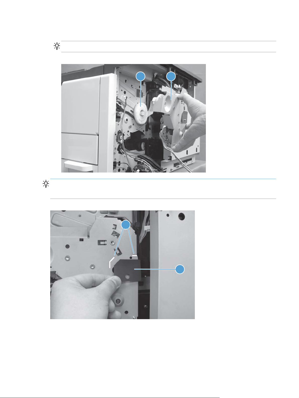
8. Remove the main drive assembly (callout 1).
TIP: When removing the main drive assembly, be careful not to drop the large gear (callout 2).
Figure 1-95 Remove the main drive assembly (7 of 7)
12
Reinstallation tip When replacing the main drive assembly, replace the sheet (callout 1), which is
included with the new assembly, at the same time. Attach the sheet along the line (callout 2) impressed
on the main drive assembly.
Figure 1-96 Reinstall the main drive assembly
2
1
ENWW
Main assemblies
63
Page 86

Fuser drive assembly
1. Remove the front cover. See Front cover on page 11.
2. On the front side of the product, disconnect six connectors (callout 1), remove the ground wire
(callout 2), and then release the cables (callout 3) from the cable guide.
Figure 1-97 Remove the fuser drive assembly (1 of 3)
1 1
3
3
2
3. Remove three screws (callout 1), and then remove the fan holder (callout 2) from the product.
Figure 1-98 Remove the fuser drive assembly (2 of 3)
2
1
64 Chapter 1 Removal and replacement ENWW
Page 87

4. Release the link (callout 1) from the pin (callout 2), remove four screws (callout 3), and then
remove the fuser drive assembly (callout 4) from the product.
Figure 1-99 Remove the fuser drive assembly (3 of 3)
1
2
4
3
When reinstalling the fuser drive assembly, complete the following steps.
1. When reassembling the fan wire, place the leading end of the wire (callout 1) in the hole (callout
2) under the front fan (callout 3) first.
Figure 1-100 Reinstall the fuser drive assembly (1 of 3)
2
3
1
ENWW
Main assemblies
65
Page 88

2. Then put the wire (callout 1) in the groove (callout 2) on the front side of the fan holder.
Figure 1-101 Reinstall the fuser drive assembly (2 of 3)
2
1
3. Finally, put the wire (callout 1) in the groove (callout 2) on the upper side of the fan holder.
Figure 1-102 Reinstall the fuser drive assembly (3 of 3)
2
1
66 Chapter 1 Removal and replacement ENWW
Page 89

Switches
The product includes the switches shown below.
Figure 1-103 Switch locations
1
2
3
4
9
5
6
8
7
Table 1-1 Switch locations
Item Description Removal process
1 Left door interlock switch See
2 Cartridge door open detection
switch
3 Test print switch This is removed as part of the formatter cage. See
4 Cartridge door interlock switch See
5 Upper cassette media width switch This is removed as part of the lifter drive assembly. See
Left door interlock switch on page 68.
See
Cartridge door open detection switch on page 73.
on page 52.
Cartridge door interlock switch on page 71.
on page 58.
Formatter cage assembly
Lifter drive assembly
ENWW
6 Lower cassette media width switch This is removed as part of the lifter drive assembly. See
on page 58.
7 Lower cassette media end switch See
8 Upper cassette media end switch See
9 Power switch assembly See
Lower cassette media end switch on page 76.
Upper cassette media end switch on page 75.
Power switch assembly on page 68.
Lifter drive assembly
Switches
67
Page 90

Power switch assembly
1. Remove the following components or assemblies:
Front cover. See
●
Fuser drive. See
●
2. Release two tabs (callout 1), and then slide the switch assembly (callout 2) in the direction
indicated to remove it from the product.
Figure 1-104 Remove the power switch assembly
Front cover on page 11.
Fuser drive assembly on page 64.
1
2
Left door interlock switch
1. Remove the following components or assemblies:
Rear cover. See
●
Low voltage power supply. See
●
Rear fan. See
●
Rear cover on page 13.
Rear fan on page 85.
Low-voltage power supply assembly on page 97.
68 Chapter 1 Removal and replacement ENWW
Page 91

2. Disconnect one connector (callout 1) on the DC controller PCA.
Figure 1-105 Remove the left door interlock switch (1 of 4)
1
3. Release one tab (callout 1), and then slide the switch cover (callout 2) in the direction indicated to
remove it from the product.
Figure 1-106 Remove the left door interlock switch (2 of 4)
1
2
ENWW
Switches
69
Page 92

4. Open the left door, unhook the spring (callout 1), release one tab (callout 2), and then remove the
lever (callout 3).
Figure 1-107 Remove the left door interlock switch (3 of 4)
2
1
3
Reinstallation tip When reinstalling the lever (callout 1), make sure that the spring (callout 2)
is placed in the lever.
Figure 1-108 Reinstall the left door lever
1
2
70 Chapter 1 Removal and replacement ENWW
Page 93

5. Release the cables (callout 1) from the cable guide, release two tabs (callout 2), and then remove
the left door interlock switch (callout 3) from the product.
Figure 1-109 Remove the left door interlock switch (4 of 4)
3
1
Cartridge door interlock switch
1. Remove the following components or assemblies:
Rear cover. See
●
Right rear cover. See
●
Formatter cage. See
●
DC controller PCA. See
●
Rear cover on page 13.
Right rear cover on page 12.
Formatter cage assembly on page 52.
DC controller PCA on page 96.
2
ENWW
Switches
71
Page 94

2. Remove two screws (callout 1) and the sheet metal cover (callout 2).
Figure 1-110 Remove the cartridge door interlock switch (1 of 4)
1
2
3. Remove one screw (callout 1) and release one tab (callout 2).
Figure 1-111 Remove the cartridge door interlock switch (2 of 4)
1
2
72 Chapter 1 Removal and replacement ENWW
Page 95

4. Remove the switch holder (callout 1).
Figure 1-112 Remove the cartridge door interlock switch (3 of 4)
1
5. Remove the cartridge door interlock switch (callout 1) from the switch holder (callout 2).
Figure 1-113 Remove the cartridge door interlock switch (4 of 4)
1
Cartridge door open detection switch
1. Remove the following components or assemblies:
Face-down cover. See
●
Rear cover. See
●
Formatter cage. See
●
Face-down cover on page 16.
Rear cover on page 13.
Formatter cage assembly on page 52.
2
ENWW
Switches
73
Page 96

2. Disconnect one connector (callout 1) (J74) on the DC controller PCA.
Figure 1-114 Remove the cartridge door open detection switch (1 of 3)
1
3. Disconnect one connector (callout 1), release the cables (callout 2) from the cable guide, release
one tab (callout 3), and then remove the switch holder (callout 4).
Figure 1-115 Remove the cartridge door open detection switch (2 of 3)
4
2
3
1
74 Chapter 1 Removal and replacement ENWW
Page 97

4. Release two tabs (callout 1), and then remove the cartridge door open detection switch from the
switch holder (callout 2).
Figure 1-116 Remove the cartridge door open detection switch (3 of 3)
12
1
Upper cassette media end switch
1. Remove the following components or assemblies:
Rear cover. See
●
Low voltage power supply. See
●
2. Disconnect one connector (callout 1), remove one screw (callout 2), and then remove the upper
cassette media end switch (callout 3) from the product.
Figure 1-117 Remove the upper cassette media end switch
Rear cover on page 13.
Low-voltage power supply assembly on page 97.
2
1
3
ENWW
Switches
75
Page 98

Lower cassette media end switch
1. Remove the following components or assemblies:
Rear cover. See
●
Formatter cage. See
●
Low voltage power supply. See
●
2. Release the cables (callout 1) from the cable guide.
Figure 1-118 Remove the lower cassette media end switch (1 of 3)
Rear cover on page 13.
Formatter cage assembly on page 52.
Low-voltage power supply assembly on page 97.
1
3. Release one tab (callout 1), and then slide the cable guide (callout 2) in the direction indicated to
remove it.
Figure 1-119 Remove the lower cassette media end switch (2 of 3)
2
1
76 Chapter 1 Removal and replacement ENWW
Page 99

4. Disconnect one connector (callout 1), remove one screw (callout 2), and then remove the lower
cassette media end switch (callout 3) from the product.
Figure 1-120 Remove the lower cassette media end switch (3 of 3)
2
1
3
ENWW
Switches
77
Page 100

Sensors
The product includes the sensors shown below.
Figure 1-121 Sensor locations
TH1
TH2
PS12
1
2
3
13
TH3
TP1
12
TH4
11
10
9
4
5
8
7
Table 1-2 Sensor locations
Item Description Removal process
1 Output bin media full sensor This is removed as part of the paper delivery assembly. See
2 Upper cassette lift-up sensor This is removed as part of the lifter drive assembly. See
3 Top of page sensor This is removed as part of the high voltage power supply. See
4 Tray 1 (MP tray) media out sensor This is removed as part of the cartridge door assembly. See
6
assembly on page 34.
Lifter drive assembly
on page 58.
power supply on page 94.
door on page 47.
Paper delivery
High-voltage
Toner cartridge
5 Lower cassette media out sensor This is removed as part of the lower cassette pickup assembly. See
cassette pickup assembly on page 56.
6 Right door sensor See
7 Upper cassette media out sensor This is removed as part of the upper cassette pickup assembly. See
8 Lower cassette lift-up sensor This is removed as part of the lifter drive assembly. See
9 Cartridge presence sensor See
10 Environment sensor See
11 Loop sensor This is removed as part of the high voltage power supply. See
Right door sensor on page 80.
cassette pickup assembly on page 53.
Lifter drive assembly
on page 58.
Cartridge presence sensor on page 79.
Environment sensor on page 79.
power supply on page 94.
Lower
Upper
High-voltage
78 Chapter 1 Removal and replacement ENWW
 Loading...