

Page 1

User Guide
Page 2

© Copyright 2018 HP Development Company,
L.P.
Windows is either a registered trademark or
trademark of Microsoft Corporation in the
United States and/or other countries.
The information contained herein is subject to
change without notice. The only warranties for
HP products and services are set forth in the
express warranty statements accompanying
such products and services. Nothing herein
should be construed as constituting an
additional warranty. HP shall not be liable for
technical or editorial errors or omissions
contained herein.
Fourth Edition: November 2018
First Edition: March 2018
Document Part Number: L14947-004
Product notice
This guide describes features that are common
to most models. Some features may not be
available on your product. To access the latest
user guide, go to http://www.hp.com/support,
and follow the instructions to nd your
product. Then select User Guides.
Software terms
By installing, copying, downloading, or
otherwise using any software product
preinstalled on this computer, you agree to be
bound by the terms of the HP End User License
Agreement (EULA). If you do not accept these
license terms, your sole remedy is to return the
entire unused product (hardware and software)
within 14 days for a full refund subject to the
refund policy of your seller.
For any further information or to request a full
refund of the price of the computer, please
contact your seller.
Page 3

About This Guide
This guide provides basic information for using and upgrading this product.
WARNING! Indicates a hazardous situation that, if not avoided, could result in death or serious injury.
CAUTION: Indicates a hazardous situation that, if not avoided, could result in minor or moderate injury.
IMPORTANT: Indicates information considered important but not hazard-related (for example, messages
related to property damage). Warns the user that failure to follow a procedure exactly as described could
result in loss of data or in damage to hardware or software. Also contains essential information to explain a
concept or to complete a task.
NOTE: Contains additional information to emphasize or supplement important points of the main text.
TIP: Provides helpful hints for completing a task.
iii
Page 4

iv About This Guide
Page 5

Table of contents
1 Product features ........................................................................................................................................... 1
Base module features ............................................................................................................................................ 1
Top components .................................................................................................................................. 1
Rear components ................................................................................................................................ 2
Side components ................................................................................................................................. 3
Regulatory information and serial number location .......................................................................... 3
HP Video Ingest Module ......................................................................................................................................... 4
HP Wireless Display Module and receiver (optional) ............................................................................................. 4
Wireless Display Module ...................................................................................................................... 4
Wireless receiver ................................................................................................................................. 5
HP Optical Disc Drive (ODD) Module (optional) ...................................................................................................... 5
HP VESA Plate (optional) ........................................................................................................................................ 6
HP Center of Room Control (CoRC) Module ............................................................................................................ 6
2 Setup ............................................................................................................................................................ 7
Connecting or removing modules .......................................................................................................................... 7
Connecting modules ............................................................................................................................ 7
Connecting the optional VESA Plate ................................................................................................... 8
Removing modules ............................................................................................................................ 10
Attaching the product to a mounting device ....................................................................................................... 11
Installing a security cable (optional) ................................................................................................................... 11
Connecting AC power ........................................................................................................................................... 12
Setting up a conferencing solution ..................................................................................................................... 13
Microsoft Skype Room System (SRS) conferencing solution ........................................................... 13
Intel Unite solution ............................................................................................................................ 20
3 Hardware upgrades ...................................................................................................................................... 26
Serviceability features ......................................................................................................................................... 26
Warnings and cautions ........................................................................................................................................ 26
Removing and replacing the access panel .......................................................................................................... 27
Removing the access panel ............................................................................................................... 27
v
Page 6

Replacing the access panel ............................................................................................................... 28
Locating internal components ............................................................................................................................ 28
Upgrading system memory ................................................................................................................................. 29
Memory module specications ......................................................................................................... 29
Populating memory module slots .................................................................................................... 30
Installing system memory modules ................................................................................................. 31
Removing and replacing a SATA SSD ................................................................................................................... 33
Appendix A Electrostatic discharge .................................................................................................................. 35
Preventing electrostatic damage ........................................................................................................................ 35
Grounding methods ............................................................................................................................................. 35
Appendix B Computer operating guidelines, routine care and shipping preparation ............................................. 36
Computer operating guidelines and routine care ............................................................................................... 36
Shipping preparation ........................................................................................................................................... 37
Appendix C Accessibility ................................................................................................................................. 38
Accessibility ......................................................................................................................................................... 38
Finding the technology tools you need ............................................................................................ 38
Our commitment ............................................................................................................................... 38
International Association of Accessibility Professionals (IAAP) ....................................................... 39
Finding the best assistive technology .............................................................................................. 39
Assessing your needs ..................................................................................................... 39
Accessibility for HP products .......................................................................................... 39
Standards and legislation .................................................................................................................................... 40
Standards .......................................................................................................................................... 40
Mandate 376 – EN 301 549 ............................................................................................ 40
Web Content Accessibility Guidelines (WCAG) ................................................................ 40
Legislation and regulations .............................................................................................................. 41
United States ................................................................................................................... 41
21st Century Communications and Video Accessibility Act (CVAA) ............................... 41
Canada ............................................................................................................................. 42
Europe ............................................................................................................................. 42
United Kingdom .............................................................................................................. 42
Australia .......................................................................................................................... 42
Worldwide ....................................................................................................................... 43
Useful accessibility resources and links .............................................................................................................. 43
Organizations .................................................................................................................................... 43
Educational institutions .................................................................................................................... 43
Other disability resources ................................................................................................................. 43
vi
Page 7

HP links .............................................................................................................................................. 44
Contacting support .............................................................................................................................................. 44
Index ............................................................................................................................................................. 45
vii
Page 8

viii
Page 9
1 Product features
Base module features
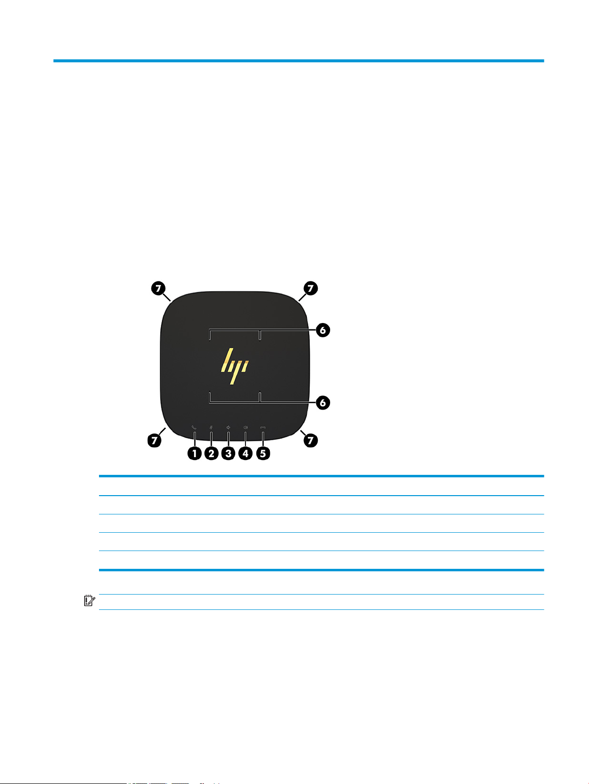
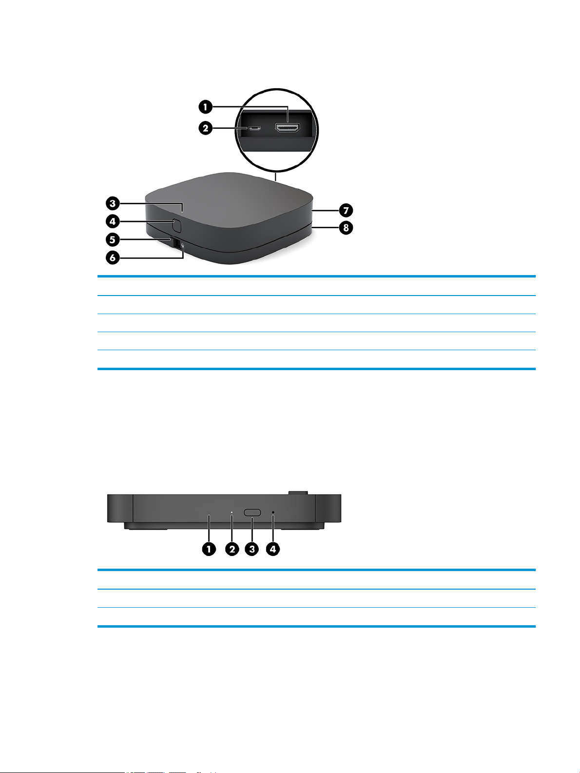
Top components
The top components enable call control with capacitive touch buttons for conference calls.
Item Component Item Component
1 Answer/Call 5 Reject/Disconnect call
2 Mute 6 Microphones
3 Volume down 7 Speakers
4 Volume up
IMPORTANT: Do not set anything on top of the system or allow liquids to get on top of the system.
Base module features 1
Page 10
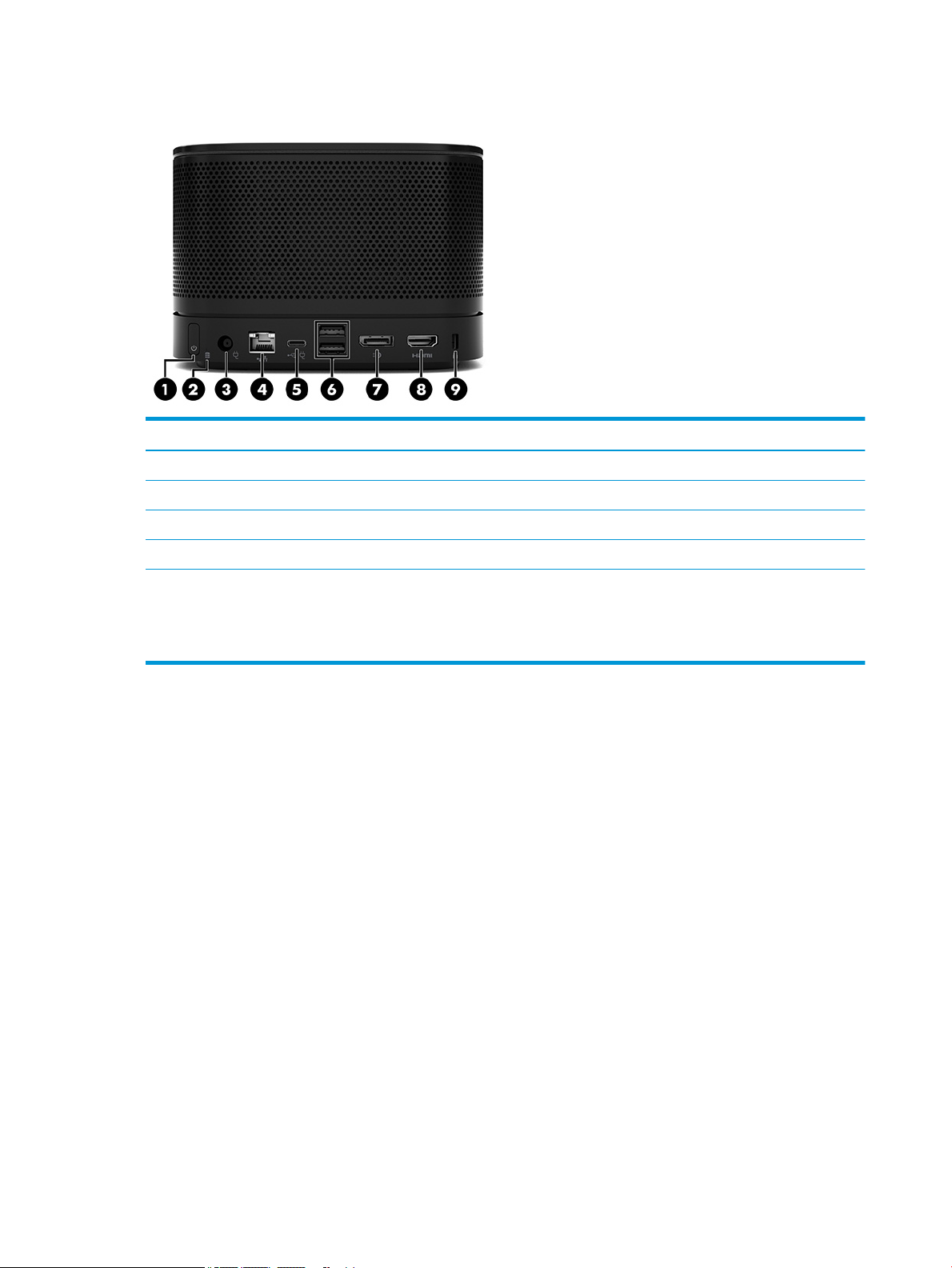
Rear components
Item Component Item Component
1 Power button 6 USB ports (2)
2 Disc activity light 7 Dual-Mode DisplayPort (D++) connector
3 Power connector 8 HDMI port
4 RJ-45 (network) jack 9 Security cable slot
5 USB Type-C power connector and port
NOTE: On the Microsoft Skype Room System (SRS)
conferencing solution, this port is designated for the HP
Center of Room Control (CoRC) Module.
2 Chapter 1 Product features
Page 11
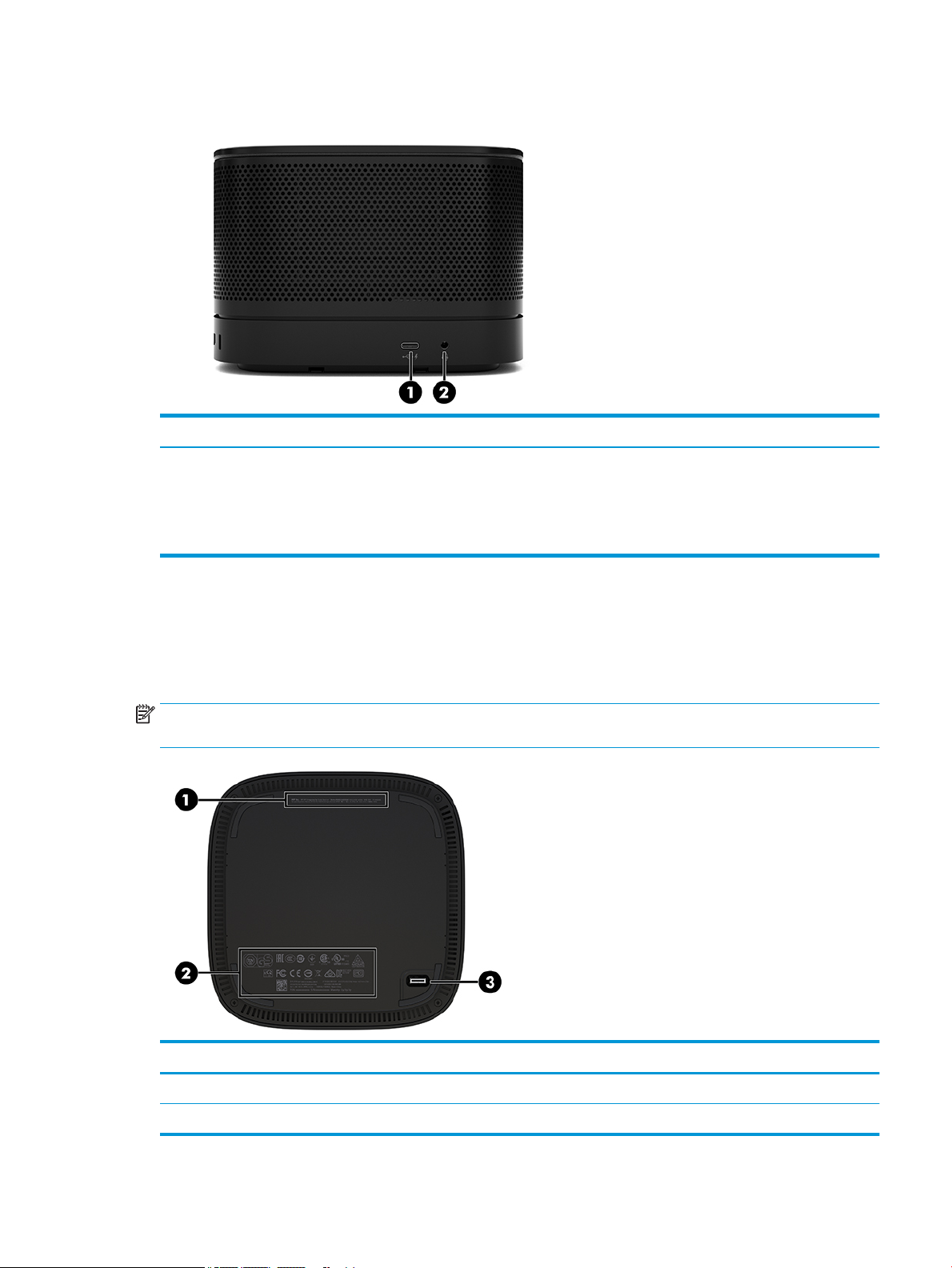
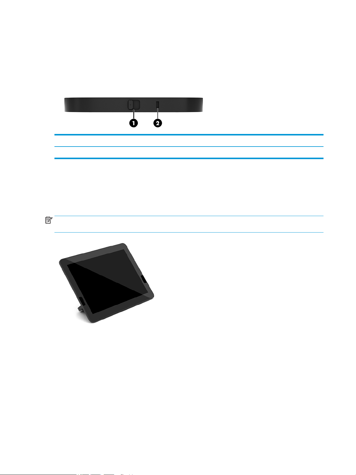
Side components
Item Component Item Component
1 USB Type-C port
(disabled at factory, enabled through system BIOS)
NOTE: This USB Type-C port does not provide power
for a monitor.
2 Audio-out (headphone)/Audio-in (microphone) combo
Regulatory information and serial number location
Each base module has a unique serial number and a product ID number laser-etched on the base cover. A copy
of these labels is inside the case. Keep these numbers available for use when contacting support for
assistance.
NOTE: If optional modules are attached to the base module, you must remove the modules to view the
serial number and product ID number.
jack
Item Component Item Component
1 Regulatory label 3 Module connector
2 Regulatory and service information
Base module features 3
Page 12
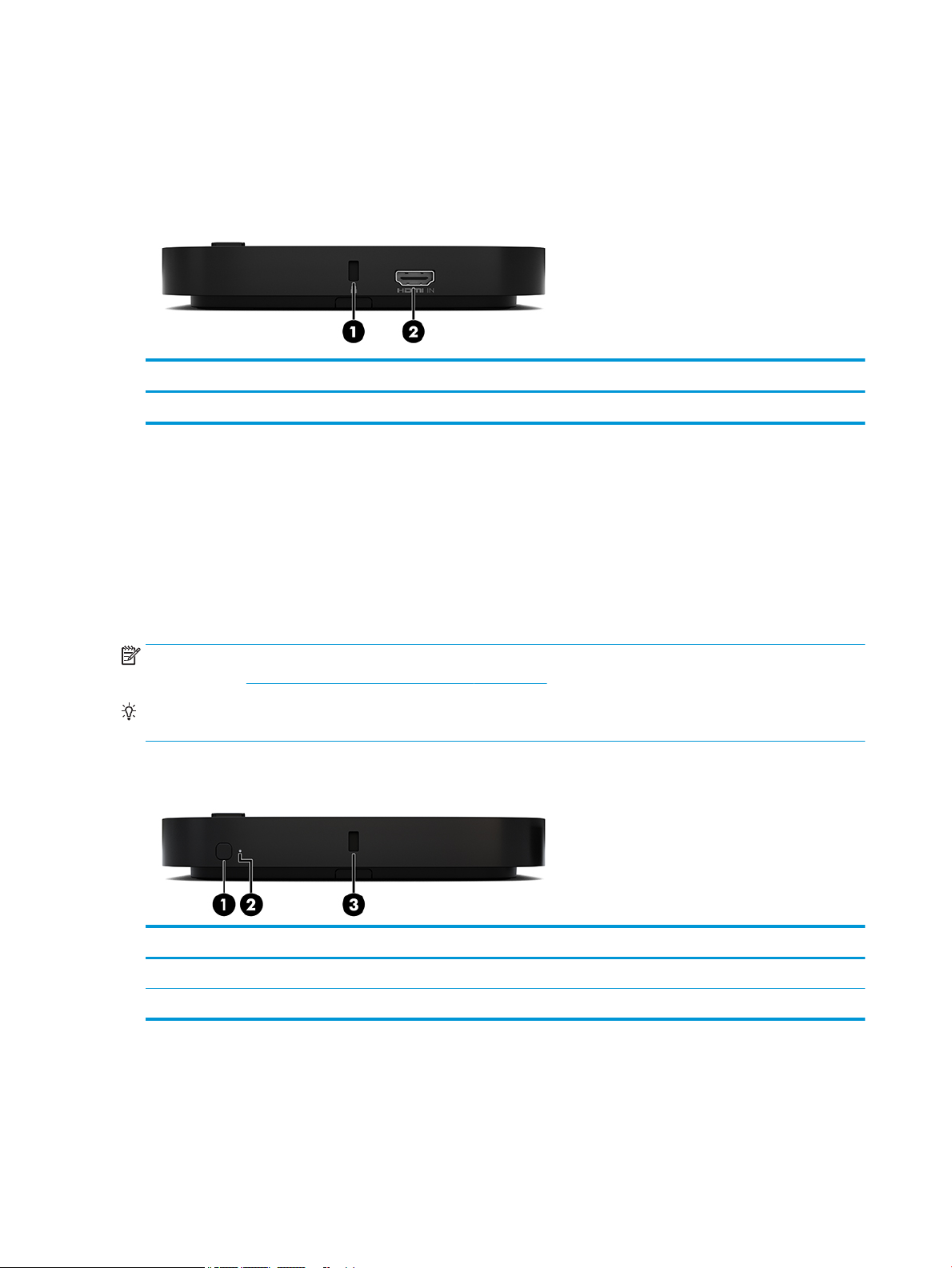
HP Video Ingest Module
The Video Ingest Module is required for installation of the Microsoft Skype Room System (SRS) software. This
module enables a video source, such as a notebook computer, to be connected to the SRS.
The Video Ingest Module is not available for the Intel Unite solution.
Item Component Item Component
1 Security cable slot 2 HDMI-in port
HP Wireless Display Module and receiver (optional)
The Wireless Display Module and receiver may be included with the Microsoft Skype Room System (SRS) or
the Intel Unite solution. The receiver can be attached to a monitor and the Wireless Display Module can
transmit a signal up to 8 meters to the receiver in the room.
An HDMI cable and USB Micro-B cable are included with the Wireless Display Module and receiver.
The Wireless Display Module is not available in all countries. Contact your seller for country support.
NOTE: The Wireless Display Module and receiver are paired at the factory but can be re-synchronized if
necessary. See Setting up a conferencing solution on page 13 for more information.
TIP: For the best performance, be sure that the line of sight between the receiver and the Wireless Display
Module is unobstructed.
Wireless Display Module
Item Component Item Component
1 Sync button 3 Security cable slot
2 Sync light
4 Chapter 1 Product features
Page 13
Wireless receiver
Item Component Item Component
1 HDMI port 5 VESA plate release button
2 USB Micro-B power connector 6 VESA plate screw hole for locking the release button
3 Sync light 7 Wireless receiver
4 Sync button 8 Wireless receiver VESA plate
HP Optical Disc Drive (ODD) Module (optional)
The optional ODD Module (purchased separately) provides optical drive functionality. Additional optical drive
modules may be connected depending upon the power supply and the total number of powered modules.
The HP Optical Disc Drive (ODD) Module may be purchased separately for the Microsoft Skype Room System
(SRS) or the Intel Unite solution.
Item Component Item Component
1 Optical drive disc tray 3 Optical drive eject button
2 Optical drive light 4 Manual eject hole
HP Optical Disc Drive (ODD) Module (optional) 5
Page 14
HP VESA Plate (optional)
The optional HP VESA Plate enables the assembly to be mounted onto a table. The product should not be
mounted to a wall or under a desk.
The HP VESA Plate may be included with the Microsoft Skype Room System (SRS) or the Intel Unite solution. It
can also be purchased separately.
Item Component Item Component
1 Quick release latch 2 Security cable slot
HP Center of Room Control (CoRC) Module
The HP Center of Room Control (CoRC) Module allows the meeting leader to easily manage the meeting by
starting meetings, adding meeting members, sharing content, and ending meeting functions. It is included
with the Microsoft Skype Room System (SRS).
NOTE: The HP Center of Room Control (CoRC) Module is required for the Microsoft Skype Room System (SRS)
conferencing solution. It is not available for the Intel Unite solution.
6 Chapter 1 Product features
Page 15

2 Setup
Connecting or removing modules
Additional modules may be attached to the base module in the following order, from top to bottom:
● Video Ingest Module (required for the Microsoft SRS only)
● Wireless Display Module (optional)
● ODD Module (optional)
● VESA Plate (optional)
Connecting modules
IMPORTANT: Before connecting modules, turn o the base module and disconnect it from any AC power
source.
Modules cannot be “hot-plugged” or “hot-swapped.”
1. Remove/disengage the security cable, if one is attached.
2. Remove all removable media, such as USB ash drives.
3. Turn o the base module properly through the operating system, and then turn o any external devices.
4. Disconnect the AC power cord from the base module and disconnect any external devices.
5. If the VESA Plate is connected, slide the quick release latch to the unlocked position and remove the
VESA Plate.
Connecting or removing modules 7
Page 16
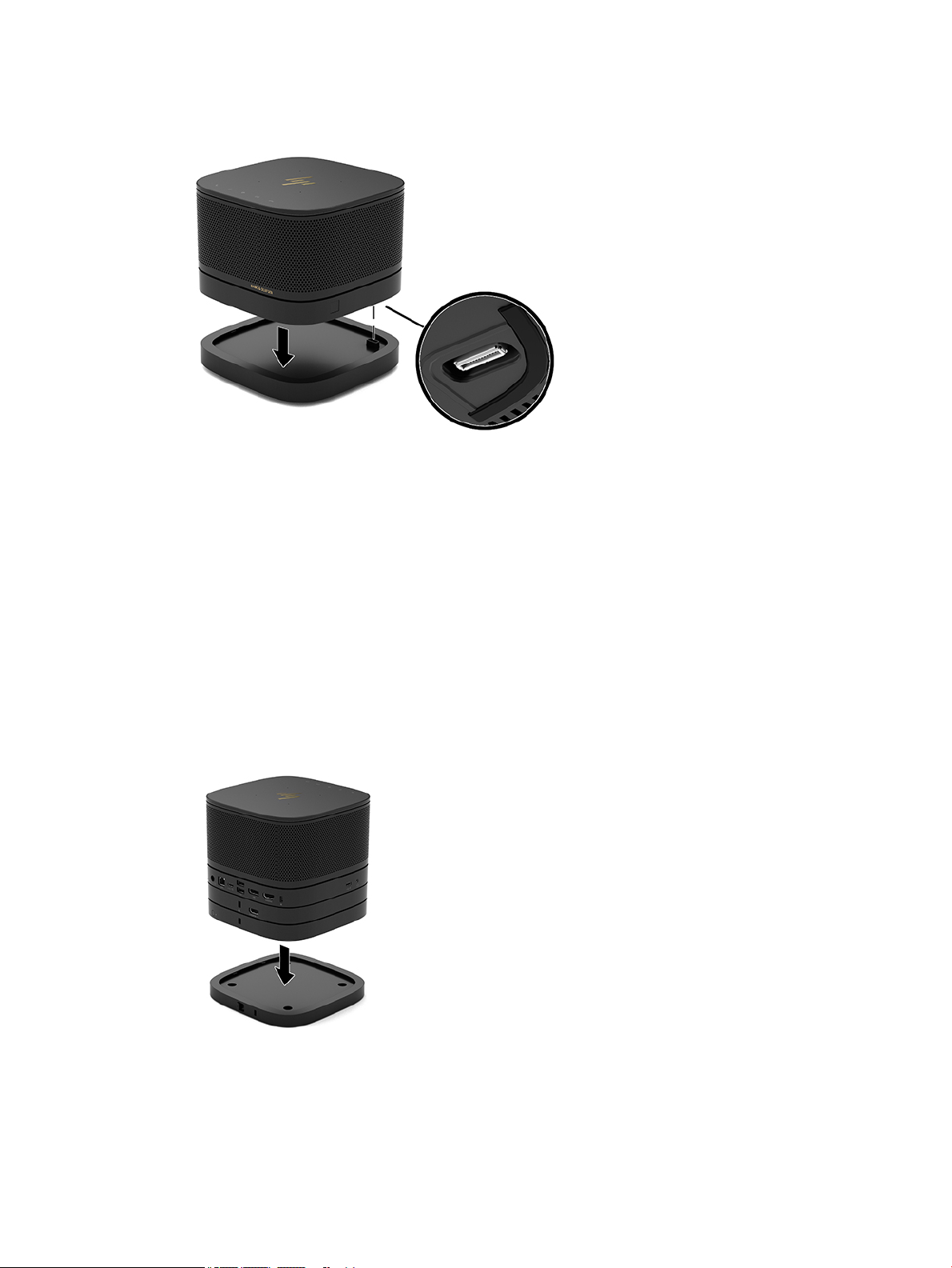
6. Align the module connection port on the underside of the base module with the module expansion
connector on the new module and press the base module down rmly.
You should hear a quiet click when the modules lock together. The module locks into place and hides the
release latch of the module above it.
Repeat until all modules have been connected.
Connecting the optional VESA Plate
If the VESA Plate is connected, the product can be mounted onto a table.
1. Slide the quick release latch on the VESA Plate to the unlocked position. Position the connected modules
over the VESA Plate.
The VESA Plate does not have a module expansion connector. Be sure that the ports of the base module
and the quick release latch and security cable slot of the VESA Plate are all on the same side.
2. Press the modules down onto the VESA Plate.
8 Chapter 2 Setup
Page 17
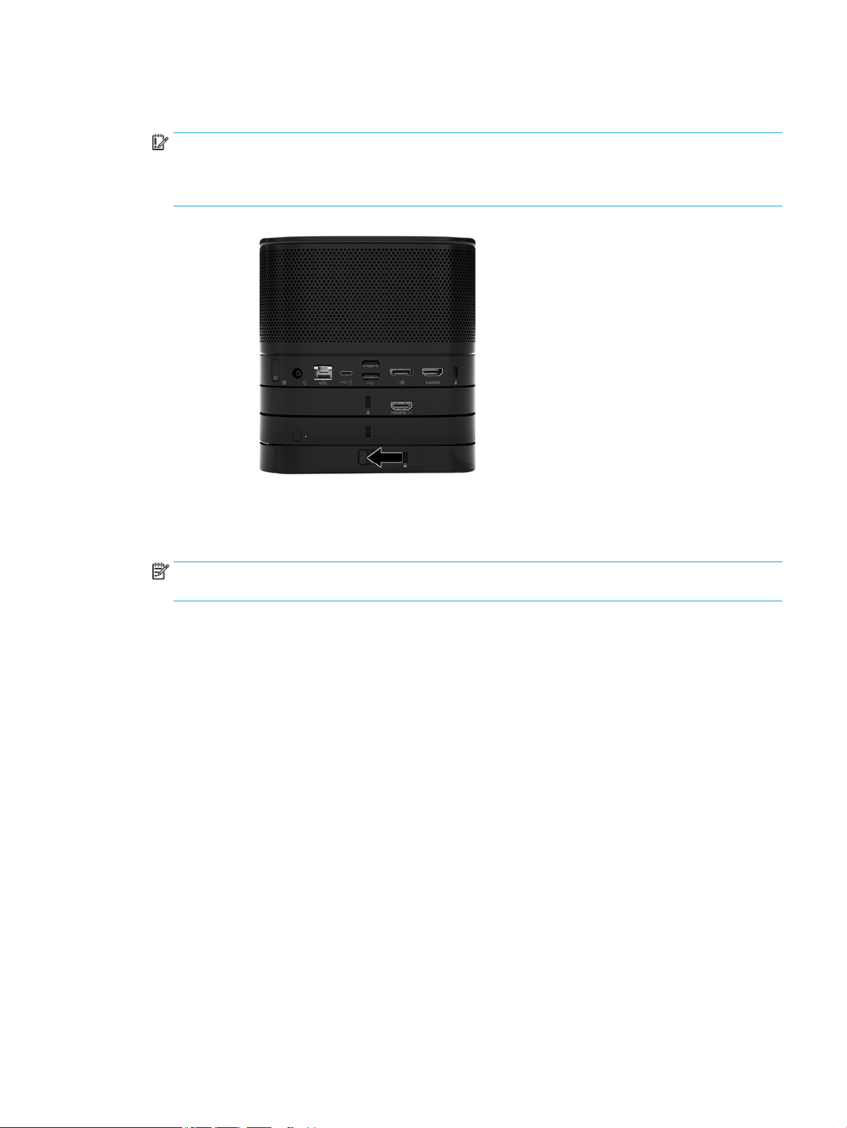
3. Slide the quick release latch on the back of the VESA Plate to the locked position to lock all modules
together.
IMPORTANT: There are four tabs in the VESA Plate. When you position the conguration correctly onto
the VESA Plate and slide the quick release latch to the locked position, the four tabs lock the VESA Plate
to the assembly. If the VESA Plate is not correctly oriented, the quick release latch cannot be moved to
the locked position and the modules are not secured.
4. Install a security cable in the VESA Plate security cable slot to prevent the quick release latch from being
unlocked and the modules from being separated.
NOTE: The security cable is designed to act as a deterrent, but it may not prevent the device from
being mishandled or stolen.
Connecting or removing modules 9
Page 18

Removing modules
IMPORTANT: Before disconnecting modules, turn o the base module and disconnect it from any AC power
source.
Modules cannot be “hot-plugged” or “hot-swapped.”
Modules must be removed one at a time, starting at the bottom. Removing the bottom module exposes the
release latch of the module above it.
1. Remove/disengage the security cable, if one is attached.
2. Remove all removable media, such as USB ash drives.
3. Turn o the base module properly through the operating system, and then turn o any external devices.
4. Disconnect the AC power cord from the base module and disconnect any external devices.
5. If the VESA Plate is connected, slide the quick release latch on the back of the VESA Plate to the unlocked
position and lift the module stack o the VESA Plate.
6. Beginning at the bottom, remove additional modules by pressing the release latch (1) on the underside
of each module until it releases the module (2) above it.
10 Chapter 2 Setup
Page 19

Attaching the product to a mounting device
If the VESA Plate, available as an option, is connected, the product can be attached to a table.
To mount the product:
1. Connect all modules except the VESA Plate.
2. Use the four screws provided with the VESA Plate to attach the VESA Plate to a table or other surface.
3. Carefully connect the modules to the VESA Plate.
4. Slide the quick release latch on the rear of the VESA Plate to the locked position to secure the VESA Plate
to the module above it.
NOTE: HP highly recommends that you secure the assembly by attaching a security cable to the rear of
the VESA Plate. This stops the quick release latch from being moved to the unlocked position and
prevents accidental release of the modules.
The security cable is designed to act as a deterrent, but it may not prevent the device from being
mishandled or stolen.
Installing a security cable (optional)
The optional 10 mm ultra-slim cable lock displayed below can be used to secure modules stacked together. A
security cable lock can be connected to the base module, the Video Ingest module, the Wireless Display
module, or the VESA Plate. When installed in the bottom module, the cable locks all modules together. If the
VESA Plate is installed, slide the quick release to the locked position and install a security cable (1) to lock all
modules together. Use the key (2) provided to lock and unlock the security cable.
Attaching the product to a mounting device 11
Page 20

NOTE: The security cable is designed to act as a deterrent, but it may not prevent the device from being
mishandled or stolen.
Connecting AC power
The HP Cable and Port Cover supplies power to the elements of the conferencing solution.
1. Connect the Cable and Port Cover to the base module:
a. Pull the port cover (1) down to expose the cable connectors.
b. Pull the rst and last connectors (2) back and then out to each side.
c. Beginning with the HDMI connector and nishing with the NIC connector, plug all middle connectors
(1) into the rear ports on the base module.
d. Connect the rst connector (2) and last connector (3).
e. Push the port cover (4) back over the cable connectors to protect and secure the connectors.
2. Connect remaining equipment, such as a CoRC or a monitor, to the Cable and Port Cover.
3. Connect the AC power cord to the AC adapter (1) and the other end to an AC outlet (2).
12 Chapter 2 Setup
Page 21

4. Connect the AC adapter to the power connector on the Cable and Port Cover (3).
Setting up a conferencing solution
The product has two conferencing solutions:
● Microsoft Skype Room System (SRS)
NOTE: For more information, go to https://docs.microsoft.com/en-us/skypeforbusiness/room-
systems.
● Intel Unite solution
NOTE: For more information, go to www.intel.com/Unite.
Microsoft Skype Room System (SRS) conferencing solution
The image below shows the SRS wiring diagram.
TIP: When routing cables under a table or other surface, use cable guides to minimize stress on the cables.
1. Connect the Video Ingest Module (required).
2. Connect additional modules, if desired.
Setting up a conferencing solution 13
Page 22

3. Place the assembly in a central location.
Be sure that nothing is placed on top of or next to the assembly that could block speakers and
microphones.
4. Connect the Cable and Port Cover:
a. Pull the port cover (1) down to expose the cable connectors.
b. Pull the rst and last connectors (2) back and then out to each side.
c. Beginning with the HDMI connector and nishing with the NIC connector, plug all middle connectors
(1) into the rear ports on the base module.
d. Connect the rst connector (2) and last connector (3).
e. Push the port cover back over the cable connectors (4) to protect and secure the connectors.
5. Connect the CoRC.
a. Connect the USB-C cable from the top of the Cable and Port Cover to an exit port on the rear of the
CoRC (1). Press the cable into the channel (2) to exit on either the left or right side of the CoRC.
14 Chapter 2 Setup
Page 23

b. Remove the CoRC back cover from the shipping box (1).
c. Remove the rubber plugs from the CoRC back cover and insert a rubber plug at the cable exit point
(2) to secure the cable.
d. Attach the back cover to the back of the CoRC (3).
Setting up a conferencing solution 15
Page 24

6. To connect the HDMI video input cable to the Video Ingest Module, insert the security strip (1) into the
slot above the HDMI port, attach the security strip clamp (2) to the HDMI cable end, and then insert the
HDMI cable end into the HDMI port on the module (3) so that the security strap is fastened by the
security clip on the cable end.
7. If the Wireless Display Module is installed, perform the following steps to install the wireless receiver:
NOTE: The receiver must face the front of the Wireless Display Module. For the best performance, be
sure that the line of sight between the receiver and the Wireless Display Module is unobstructed.
a. Connect a monitor power cord to an AC outlet (1).
b. Use the included adhesive strip to secure the receiver in place (2). Make sure the portion of the
receiver with the sync button and light is not hidden behind the monitor so that there is a clear line
of sight between the Wireless Display Module and receiver.
16 Chapter 2 Setup
Page 25

c. Connect the receiver to the HDMI port and a powered USB port on the monitor (3) using the HDMI
cable and USB Micro-B cable included with the Wireless Display Module and receiver.
NOTE: For wireless functionality, the monitor USB port that connects the receiver must provide
power at all times. Be sure that the monitor settings allow the USB port to provide power when the
monitor is in the sleep state.
Alternatively, use the two included screws to mount the receiver VESA plate (1) onto a wall or table, and
then press the receiver rmly onto the plate (2) until it clicks into place.
To remove the receiver from the VESA plate, slide the release button on the VESA plate. The receiver will
pop up, allowing it to be pulled away from the VESA plate.
Make sure that the front of the receiver is facing the front of the Wireless Display Module and that the
line of sight between the receiver and the Wireless Display Module is unobstructed. The wireless feature
will not work if the antennas are not facing each other or if there is something blocking their line of
sight. The receiver should also be no more than 8 meters (26.6 feet) from the Wireless Display Module
and within a 90-degree angle.
Setting up a conferencing solution 17
Page 26

NOTE: The front of the receiver with the antenna that needs to be facing the Wireless Display Module
can be identied by the sync light on the receiver. See Wireless receiver on page 5 to locate the sync
light on the receiver.
NOTE: The Wireless Display Module and receiver are paired at the factory. When the system is turned
on, the lights on the module and receiver are solid. If they are not solid, press the sync button on both
the module and receiver. The lights will ash slowly while the module and receiver search for each other,
then blink faster when the module and receiver recognize each other, and then become solid when the
module and receiver establish a connection. If the module and receiver do not connect, check to be sure
that the line of sight between the module and receiver is unobstructed. The lights are o when the
system is turned o or in the sleep state.
8. To connect a monitor without the Wireless Display Module, perform the following steps:
a. Connect a monitor power cord to an AC outlet (1).
18 Chapter 2 Setup
Page 27

b. Connect the monitor to an HDMI or DisplayPort connector (2) on the Cable and Port Cover.
NOTE: If dual HDMI ports are required, use an active DisplayPort-to-HDMI adapter to add the
second HDMI port.
9. Connect an optional USB camera to a USB Type-A port on the Cable and Port Cover.
10. Connect a local area network (LAN) cable to an RJ-45 (network) jack on the Cable and Port Cover.
11. Connect the AC power cord to the AC adapter (1) and the other end to an AC outlet (2).
Setting up a conferencing solution 19
Page 28

12. Connect the AC adapter to the power connector on the Cable and Port Cover (3).
13. Press the power button.
14. Follow the Microsoft Skype Room System (SRS) instructions to install the conferencing software.
Intel Unite solution
The image below shows the Intel Unite solution wiring diagram.
20 Chapter 2 Setup
Page 29

TIP: When routing cables under a table or other surface, use cable guides to minimize stress on the cables.
1. Connect the desired modules.
2. Place the product in a central location.
Be sure that nothing is placed on top of or next to the product that could block speakers and
microphones.
3. Connect the Cable and Port Cover:
a. Pull the port cover (1) down to expose the cable connectors.
b. Pull the rst and last connectors (2) back and then out to each side.
c. Beginning with the HDMI connector and nishing with the NIC connector, plug all middle connectors
(1) into the rear ports on the base module.
d. Connect the rst connector (2) and last connector (3).
e. Push the port cover (4) back over the cable connectors to protect and secure the connectors.
4. If the Wireless Display Module is installed, perform the following steps to install the wireless receiver:
NOTE: The receiver must face the front of the Wireless Display Module. For the best performance, be
sure that the line of sight between the receiver and the Wireless Display Module is unobstructed.
Setting up a conferencing solution 21
Page 30

a. Connect a monitor power cord to an AC outlet (1).
b. Use the included adhesive strip to secure the receiver in place (2). Make sure the portion of the
receiver with the sync button and light is not hidden behind the monitor so that there is a clear line
of sight between the Wireless Display Module and receiver.
c. Connect the receiver to the HDMI port and a powered USB port on the monitor (3) using the HDMI
cable and USB Micro-B cable included with the Wireless Display Module and receiver.
NOTE: For wireless functionality, the monitor USB port that connects the receiver must provide
power at all times. Be sure that the monitor settings allow the USB port to provide power when the
monitor is in the sleep state.
Alternatively, use the two included screws to mount the receiver VESA plate (1) onto a wall or table, and
then press the receiver rmly onto the plate (2) until it clicks into place.
To remove the receiver from the VESA plate, slide the release button on the VESA plate. The receiver will
pop up, allowing it to be pulled away from the VESA plate.
22 Chapter 2 Setup
Page 31

Make sure that the front of the receiver is facing the front of the Wireless Display Module and that the
line of sight between the receiver and the Wireless Display Module is unobstructed. The wireless feature
will not work if the antennas are not facing each other or if there is something blocking their line of
sight. The receiver should also be no more than 8 meters (26.6 feet) from the Wireless Display Module
and within a 90-degree angle.
NOTE: The front of the receiver with the antenna that needs to be facing the Wireless Display Module
can be identied by the sync light on the receiver. See Wireless receiver on page 5 to locate the sync
light on the receiver.
NOTE: The Wireless Display Module and receiver are paired at the factory. When the system is turned
on, the lights on the module and receiver are solid. If they are not solid, press the sync button on both
the module and receiver. The lights will ash slowly while the module and receiver search for each other,
then blink faster when the module and receiver recognize each other, and then become solid when the
module and receiver establish a connection. If the module and receiver do not connect, check to be sure
that the line of sight between the module and receiver is unobstructed. The lights are o when the
system is turned o or in the sleep state.
5. To connect a monitor without the Wireless Display Module, perform the following steps:
a. Connect a monitor power cord to an AC outlet (1). You may instead connect the monitor to a
powered USB Type-C port (2) on the Cable and Port Cover.
Setting up a conferencing solution 23
Page 32

b. Connect the monitor to an HDMI or DisplayPort connector (3) on the Cable and Port Cover. The USB
Type-C port (2) on the Cable and Port Cover can also be used to connect the monitor.
NOTE: If dual HDMI ports are required, use an active DisplayPort-to-HDMI adapter to add the
second HDMI port.
6. Connect an optional USB camera to a USB Type-A port on the Cable and Port Cover.
7. Connect a local area network (LAN) to an RJ-45 (network) jack on the Cable and Port Cover.
8. Connect the AC power cord to the AC adapter (1) and the other end to an AC outlet (2).
24 Chapter 2 Setup
Page 33

9. Connect the AC adapter to the power connector on the Cable and Port Cover (3).
10. Press the power button.
11. Follow the Intel Unite solution instructions to install the conferencing software.
Setting up a conferencing solution 25
Page 34

3 Hardware upgrades
Serviceability features
The computer includes features that make it easy to upgrade and service.
Warnings and cautions
Before performing upgrades, be sure to carefully read all of the applicable instructions, cautions, and
warnings in this guide.
WARNING! To reduce the risk of personal injury from electric shock, hot surfaces, or re:
Disconnect the AC power cord from the AC outlet before removing the enclosure. Energized and moving parts
are inside.
Allow the internal system components to cool before you touch them.
Replace and secure the enclosure before restoring power to the equipment.
Do not connect telecommunications or telephone connectors to the network interface controller (NIC)
receptacles.
Do not disable the AC power cord grounding plug. The grounding plug is an important safety feature.
Plug the AC power cord into a grounded (earthed) AC outlet that is easily accessible at all times.
To reduce the risk of serious injury, read the Safety & Comfort Guide. It describes proper workstation setup,
and proper posture, health, and work habits for computer users. The Safety & Comfort Guide also provides
important electrical and mechanical safety information. The Safety & Comfort Guide is available on the Web
at http://www.hp.com/ergo.
IMPORTANT: Static electricity can damage the electrical components of the computer or optional
equipment. Before beginning these procedures, ensure that you are discharged of static electricity by briey
touching a grounded metal object. See Electrostatic discharge on page 35 for more information.
When the computer is plugged into an AC power source, voltage is always applied to the system board. You
must disconnect the AC power cord from the power source before opening the computer to prevent damage
to internal components.
26 Chapter 3 Hardware upgrades
Page 35

Removing and replacing the access panel
Removing the access panel
The access panel must be removed to access the solid-state drive (SSD) and system memory modules.
1. Remove the base module from any additional modules.
For instructions, see Removing modules on page 10.
2. Place the product upside down on a at surface covered with a soft cloth to protect the product from
scratches or other damage.
3. Loosen the four captive screws securing the access panel, and lift the panel o the base module.
Removing and replacing the access panel 27
Page 36

Replacing the access panel
1. Place the product upside down on a at surface covered with a soft cloth.
2. Align the access panel with the base module so that the module connection port is clearly visible
through the opening in the access panel.
3. Tighten the four captive screws to secure the access panel to the base module.
4. Reconnect any additional modules.
For instructions, see Connecting or removing modules on page 7.
Locating internal components
Item Component Item Component
1 System memory modules 2 SSD
28 Chapter 3 Hardware upgrades
Page 37

Upgrading system memory
The memory module slots on the system board can be populated with up to two industry-standard memory
modules. At least one small outline, dual inline memory module (SODIMM) is preinstalled. To achieve the
maximum memory support, you can populate the system board with up to 32 GB (16 GB x 2) of memory.
NOTE: Dual channel memory is recommended for Microsoft SRS for better performance.
Memory module specications
For proper system operation, the SODIMMs must adhere to the following specications:
● Industry-standard 288-pins
● Unbuered non-ECC PC4-17000 DDR4-2133 MHz-compliant
● 1.2 volt DDR4-SDRAM SODIMMs
● Support CAS latency 15 DDR4 2400 MHz (15-15-15 timing)
● Contain the mandatory Joint Electronic Device Engineering Council (JEDEC) specication
The product supports the following:
● 512-Mbit, 1-Gbit, and 2-Gbit non-ECC memory technologies
● Single-sided and double-sided SODIMMs
● SODIMMs constructed with x8 and x16 devices
NOTE: To avoid compatibility issues, HP recommends that you use only HP memory modules in this product.
The system will not operate properly if you install unsupported DIMM memory. DIMMs constructed with x4
SDRAM are not supported.
Upgrading system memory 29
Page 38

Populating memory module slots
There are two memory module slots, one slot per channel. The slots are labeled DIMM1 and DIMM3. The
DIMM1 slot operates in memory channel B. The DIMM3 slot operates in memory channel A.
Item Description System board label Slot color
1 Memory 1 slot, Channel B DIMM1 Black
2 Memory 3 slot, Channel A DIMM3 Black
The system automatically operates in single-channel mode, dual-channel mode, or ex mode, depending on
how the memory modules are installed.
● The system operates in single-channel mode if only one memory module slot is populated.
● The system operates in higher-performing, dual-channel mode if the capacity of the memory modules
in Channel A and Channel B are equal.
● The system operates in ex mode if the capacity of the memory modules in Channel A and Channel B are
not equal. In ex mode, the channel populated with the least amount of memory determines the total
amount of memory that is assigned to dual-channel operation, and the remainder is assigned to singlechannel operation. In ex mode, install the memory module with the larger capacity in the DIMM3 slot
(Channel A).
● In any mode, the maximum operational speed is determined by the slowest memory module in the
system.
30 Chapter 3 Hardware upgrades
Page 39

Installing system memory modules
IMPORTANT: You must disconnect the AC power cord and wait approximately 30 seconds for the power to
drain before adding or removing memory modules. Regardless of the power-on state, voltage is always
supplied to the memory modules as long as the system is plugged into an active AC outlet. Adding or
removing memory modules while voltage is present may cause irreparable damage to the memory modules
or system board.
The memory module slots have gold-plated metal contacts. When upgrading the memory, it is important to
use memory modules with gold-plated metal contacts to prevent corrosion and/or oxidation resulting from
having incompatible metals in contact with each other.
Static electricity can damage the electronic components of the system or optional cards. Before beginning
these procedures, ensure that you are discharged of static electricity by
object. For more information, see Electrostatic discharge on page 35.
When handling a memory module, be careful not to touch any of the contacts. Doing so may damage the
module.
1. Remove the access panel.
For instructions, see Removing the access panel on page 27.
2. To remove a memory module, press outward on the two latches on each side of the memory module (1),
and then pull the memory module out of the slot (2).
briey touching a grounded metal
Upgrading system memory 31
Page 40

3. Insert the new memory module into the slot at approximately a 30° angle (1), and then press the
memory module (2) down so that the latches lock it in place.
NOTE: A memory module can be installed in only one way. Match the notch on the module with the tab
on the memory module slot.
4. Replace the access panel.
For instructions, see Replacing the access panel on page 28.
The system automatically recognizes the additional memory when you turn on the system.
32 Chapter 3 Hardware upgrades
Page 41

Removing and replacing a SATA SSD
NOTE: Back up the SSD before you remove it so that you can transfer the data to the new SSD.
To add an SSD instead of replacing one, purchase a 4-screw after-market option kit to obtain the screws
required to mount the drive.
1. Remove the access panel.
For instructions, see Removing the access panel on page 27.
2. Remove the 4 screws (1) attaching the SSD cage to the system board and lift the cage (2) out of the
chassis.
3. Pull the tab (3) to disconnect the SSD power-and-data cable from the SSD.
4. Remove the screws (1) securing the SSD in the cage and lift the SSD (2) out of the cage.
5. Position the new SSD over the drive cage with the SSD connectors at the end with the thermal patch and
the circuit board side facing the closed side of the drive cage.
Removing and replacing a SATA SSD 33
Page 42

6. Set the new SSD (1) into the cage. Be sure that the label side of the SSD is visible.
7. Fasten the four screws (2) to secure the SSD in the cage.
8. Connect the power-and-data cable (1) to the SSD.
9. Set the drive cage (2) in the chassis. Be sure that the SSD connectors are facing the back of the chassis.
10. Align the drive cage tabs with the screw posts in the chassis and fasten the four screws (3) to secure the
SSD.
11. Replace the access panel.
For instructions, see Replacing the access panel on page 28.
34 Chapter 3 Hardware upgrades
Page 43

A Electrostatic discharge
A discharge of static electricity from a nger or other conductor may damage system boards or other staticsensitive devices. This type of damage may reduce the life expectancy of the device.
Preventing electrostatic damage
To prevent electrostatic damage, observe the following precautions:
● Avoid hand contact by transporting and storing products in static-safe containers.
● Keep electrostatic-sensitive parts in their containers until they arrive at static-free workstations.
● Place parts on a grounded surface before removing them from their containers.
● Avoid touching pins, leads, or circuitry.
● Always be properly grounded when touching a static-sensitive component or assembly.
Grounding methods
Use one or more of the following methods when handling or installing electrostatic-sensitive parts:
● Use a wrist strap connected by a ground cord to a grounded workstation or computer chassis. Wrist
straps are exible straps with a minimum of 1 megohm +/- 10 percent resistance in the ground cords. To
provide proper ground, wear the strap snug against the skin.
● Use heelstraps, toestraps, or bootstraps at standing workstations. Wear the straps on both feet when
standing on conductive oors or dissipating oor mats.
● Use conductive eld service tools.
● Use a portable eld service kit with a folding static-dissipating work mat.
If you do not have any of the suggested equipment for proper grounding, contact an HP authorized dealer,
reseller, or service provider.
NOTE: For more information on static electricity, contact an HP authorized dealer, reseller, or service
provider.
Preventing electrostatic damage 35
Page 44

B Computer operating guidelines, routine
care and shipping preparation
Computer operating guidelines and routine care
Follow these guidelines to properly set up and care for the computer and monitor:
● Keep the computer away from excessive moisture, direct sunlight, and extremes of heat and cold.
● Operate the computer on a sturdy, level surface. Leave a 10.2 cm (4 in) clearance on all vented sides of
the computer and above the monitor to permit the required airow.
● Never restrict the airow into the computer by blocking any vents or air intakes. Do not place the
keyboard, with the keyboard feet down, directly against the front of the desktop unit as this also
restricts airow.
● Never operate the computer with the access panel or any of the expansion card slot covers removed.
● Do not stack computers on top of each other or set anything on top of the computer.
● Do not place computers so near each other that they are subject to each other’s recirculated or
preheated air.
● If the computer is to be operated within a separate enclosure, intake and exhaust ventilation must be
provided on the enclosure, and the same operating guidelines listed above will still apply.
● Keep liquids away from the computer and keyboard. Do not allow liquids to get on top of the computer.
● Never cover the ventilation slots on the monitor with any type of material.
● Install or enable power management functions of the operating system or other software, including
sleep states.
● Turn o the computer before you do either of the following:
● Wipe the exterior of the computer with a soft, damp cloth as needed. Using cleaning products may
discolor or damage the nish.
● Occasionally clean the air vents on all vented sides of the computer. Lint, dust, and other foreign
matter can block the vents and limit the airow.
36 Appendix B Computer operating guidelines, routine care and shipping preparation
Page 45

Shipping preparation
Follow these suggestions when preparing to ship the computer:
1. Back up the SSD les to an external storage device. Be sure that the backup media is not exposed to
electrical or magnetic impulses while stored or in transit.
NOTE: The SSD locks automatically when the system power is turned o.
2. Remove and store all removable media.
3. Turn o the computer and external devices.
4. Disconnect the AC power cord from the AC outlet and then from the computer.
5. Disconnect the system components and external devices from their power sources and then from the
computer.
NOTE: Ensure that all boards are seated properly and secured in the board slots before shipping the
computer.
6. Pack the system components and external devices in their original packing boxes or similar packaging,
with suicient packing material to protect them.
Shipping preparation 37
Page 46

C Accessibility
Accessibility
HP is working to weave diversity, inclusion and work/life into the fabric of our company, so it is reected in
everything we do. Here are some examples of how we are putting dierences to work to create an inclusive
environment focused on connecting people to the power of technology throughout the world.
Finding the technology tools you need
Technology can unleash your human potential. Assistive technology removes barriers and helps you create
independence at home, at work, and in the community. Assistive technology helps increase, maintain, and
improve the functional capabilities of electronic and information technology. For more information, see
Finding the best assistive technology on page 39.
Our commitment
HP is committed to providing products and services that are accessible for people with disabilities. This
commitment supports our company's diversity objectives and helps us ensure that the benets of technology
are available to all.
Our accessibility goal is to design, produce, and market products and services that can be eectively used by
everyone, including people with disabilities, either on a stand-alone basis or with appropriate assistive
devices.
To achieve our goal, this Accessibility Policy establishes seven key objectives to guide our actions as a
company. All HP managers and employees are expected to support these objectives and their implementation
in accordance with their roles and responsibilities:
● Raise the level of awareness of accessibility issues within our company, and provide our employees with
the training they need to design, produce, market, and deliver accessible products and services.
● Develop accessibility guidelines for products and services, and hold product development groups
accountable for implementing these guidelines where competitively, technically, and economically
feasible.
● Involve people with disabilities in the development of accessibility guidelines, and in the design and
testing of products and services.
● Document accessibility features and make information about our products and services publicly
available in an accessible form.
● Establish relationships with leading assistive technology and solution providers.
38 Appendix C Accessibility
Page 47

● Support internal and external research and development that will improve assistive technology relevant
to our products and services.
● Support and contribute to industry standards and guidelines for accessibility.
International Association of Accessibility Professionals (IAAP)
IAAP is a not-for-prot association focused on advancing the accessibility profession through networking,
education, and certication. The objective is to help accessibility professionals develop and advance their
careers and to better enable organizations to integrate accessibility into their products and infrastructure.
HP is a founding member, and we joined to participate with other organizations to advance the eld of
accessibility. This commitment supports our company’s accessibility goal of designing, producing, and
marketing products and services that can be eectively used by people with disabilities.
IAAP will make our profession strong by globally connecting individuals, students, and organizations to learn
from one another. If you are interested in learning more, go to http://www.accessibilityassociation.org to join
the online community, sign up for newsletters, and learn about membership options.
Finding the best assistive technology
Everyone, including people with disabilities or age-related limitations, should be able to communicate,
express themselves, and connect with the world using technology. HP is committed to increasing accessibility
awareness within HP and with our customers and partners. Whether it’s large fonts that are easy on the eyes,
voice recognition that lets you give your hands a rest, or any other assistive technology to help with your
specic situation—a variety of assistive technologies make HP products easier to use. How do you choose?
Assessing your needs
Technology can unleash your potential. Assistive technology removes barriers and helps you create
independence at home, at work, and in the community. Assistive technology (AT) helps increase, maintain,
and improve the functional capabilities of electronic and information technology.
You may choose from many AT products. Your AT assessment should allow you to evaluate several products,
answer your questions, and facilitate your selection of the best solution for your situation. You will nd that
professionals qualied to do AT assessments come from many elds, including those licensed or certied in
physical therapy, occupational therapy, speech/language pathology, and other areas of expertise. Others,
while not certied or licensed, may also provide evaluation information. You will want to ask about the
individual's experience, expertise, and fees to determine if they are appropriate for your needs.
Accessibility for HP products
The following links provide information on accessibility features and assistive technology, if applicable,
included in various HP products. These resources will help you select the specic assistive technology
features and product(s) most appropriate for your situation.
● HP Elite x3–Accessibility Options (Windows 10 Mobile)
● HP PCs–Windows 7 Accessibility Options
● HP PCs–Windows 8 Accessibility Options
● HP PC’s–Windows 10 Accessibility Options
● HP Slate 7 Tablets–Enabling Accessibility Features on Your HP Tablet (Android 4.1/Jelly Bean)
● HP SlateBook PCs–Enabling Accessibility Features (Android 4.3, 4.2/Jelly Bean)
Accessibility 39
Page 48

● HP Chromebook PCs–Enabling Accessibility Features on Your HP Chromebook or Chromebox (Chrome
OS)
● HP Shopping–peripherals for HP products
If you need additional support with the accessibility features on your HP product, see Contacting support
on page 44.
Additional links to external partners and suppliers that may provide additional assistance:
● Microsoft Accessibility information (Windows 7, Windows 8, Windows 10, Microsoft Oice)
● Google Products accessibility information (Android, Chrome, Google Apps)
● Assistive Technologies sorted by impairment type
● Assistive Technologies sorted by product type
● Assistive Technology vendors with product descriptions
● Assistive Technology Industry Association (ATIA)
Standards and legislation
Standards
Section 508 of the Federal Acquisition Regulation (FAR) standards was created by the US Access Board to
address access to information and communication technology (ICT) for people with physical, sensory, or
cognitive disabilities. The standards contain technical criteria specic to various types of technologies, as well
as performance-based requirements which focus on functional capabilities of covered products. Specic
criteria cover software applications and operating systems, web-based information and applications,
computers, telecommunications products, video and multi-media, and self-contained closed products.
Mandate 376 – EN 301 549
The EN 301 549 standard was created by the European Union within Mandate 376 as the basis for an online
toolkit for public procurement of ICT products. The standard species the functional accessibility
requirements applicable to ICT products and services, together with a description of the test procedures and
evaluation methodology for each accessibility requirement.
Web Content Accessibility Guidelines (WCAG)
Web Content Accessibility Guidelines (WCAG) from the W3C's Web Accessibility Initiative (WAI) helps web
designers and developers create sites that better meet the needs of people with disabilities or age-related
limitations. WCAG advances accessibility across the full range of web content (text, images, audio, and video)
and web applications. WCAG can be precisely tested, is easy to understand and use, and allows web
developers exibility for innovation. WCAG 2.0 has also been approved as ISO/IEC 40500:2012.
WCAG specically addresses barriers to accessing the web experienced by people with visual, auditory,
physical, cognitive, and neurological disabilities, and by older web users with accessibility needs. WCAG 2.0
provides characteristics of accessible content:
40 Appendix C Accessibility
Page 49

● Perceivable (for instance, by addressing text alternatives for images, captions for audio, adaptability of
presentation, and color contrast)
● Operable (by addressing keyboard access, color contrast, timing of input, seizure avoidance, and
navigability)
● Understandable (by addressing readability, predictability, and input assistance)
● Robust (for instance, by addressing compatibility with assistive technologies)
Legislation and regulations
Accessibility of IT and information has become an area of increasing legislative importance. This section
provides links to information on key legislation, regulations, and standards.
● United States
● Canada
● Europe
● United Kingdom
Australia
●
● Worldwide
United States
Section 508 of the Rehabilitation Act species that agencies must identify which standards apply to the
procurement of ICT, perform market research to determine the availability of accessible products and
services, and document the results of their market research. The following resources provide assistance in
meeting Section 508 requirements:
● www.section508.gov
● Buy Accessible
The U.S. Access Board is currently updating the Section 508 standards. This eort will address new
technologies and other areas where the standards need to be modied. For more information, go to Section
508 Refresh.
Section 255 of the Telecommunications Act requires telecommunications products and services to be
accessible to people with disabilities. FCC rules cover all hardware and software telephone network
equipment and telecommunications equipment used in the home or oice. Such equipment includes
telephones, wireless handsets, fax machines, answering machines, and pagers. FCC rules also cover basic and
special telecommunications services, including regular telephone calls, call waiting, speed dialing, call
forwarding, computer-provided directory assistance, call monitoring, caller identication, call tracing, and
repeat dialing, as well as voice mail and interactive voice response systems that provide callers with menus of
choices. For more information, go to Federal Communication Commission Section 255 information.
21st Century Communications and Video Accessibility Act (CVAA)
The CVAA updates federal communications law to increase the access of persons with disabilities to modern
communications, updating accessibility laws enacted in the 1980s and 1990s to include new digital,
broadband, and mobile innovations. Regulations are enforced by the FCC and documented as 47 CFR Part 14
and Part 79.
Standards and legislation 41
Page 50

Canada
Europe
● FCC Guide on the CVAA
Other U.S. legislation and initiatives
● Americans with Disabilities Act (ADA), Telecommunications Act, the Rehabilitation Act and others
The Accessibility for Ontarians with Disabilities Act was established to develop and implement accessibility
standards to make goods, services, and facilities accessible to Ontarians with disabilities and to provide for
the involvement of persons with disabilities in the development of the accessibility standards. The rst
standard of the AODA is the customer service standard; however, standards for transportation, employment,
and information and communication are also being developed. The AODA applies to the Government of
Ontario, the Legislative Assembly, every designated public sector organization, and to every other person or
organization that provides goods, services, or facilities to the public or other third parties and that has at
least one employee in Ontario; and accessibility measures must be implemented on or before January 1,
2025. For more information, go to Accessibility for Ontarians with Disability Act (AODA) .
EU Mandate 376 ETSI Technical Report ETSI DTR 102 612: "Human Factors (HF); European accessibility
requirements for public procurement of products and services in the ICT domain (European Commission
Mandate M 376, Phase 1)" has been released.
Background: The three European Standardization Organizations have set up two parallel project teams to
carry out the work specied in the European Commission "Mandate 376 to CEN, CENELEC and ETSI, in Support
of Accessibility Requirements for Public Procurement of Products and Services in the ICT Domain."
ETSI TC Human Factors Specialist Task Force 333 has developed ETSI DTR 102 612. Further details about the
work performed by STF333 (e.g., Terms of Reference, specication of the detailed work tasks, time plan for
the work, previous drafts, listing of comments received and means to contact the task force) can be found at
the Special Task Force 333.
The parts relating to the assessment of suitable testing and conformity schemes were carried out by a
parallel project, detailed in CEN BT/WG185/PT. For further information, go to the CEN project team website.
The two projects are closely coordinated.
● CEN project team
● European Commission mandate for e-accessibility (PDF 46KB)
United Kingdom
The Disability Discrimination Act of 1995 (DDA) was enacted to ensure that websites are accessible to blind
and disabled users in the United Kingdom.
● W3C UK Policies
Australia
The Australian government has announced their plan to implement Web Content Accessibility Guidelines 2.0.
All Australian government websites will require Level A compliance by 2012, and Double A by 2015. The new
standard replaces WCAG 1.0, which was introduced as a mandated requirement for agencies in 2000.
42 Appendix C Accessibility
Page 51

Worldwide
● JTC1 Special Working Group on Accessibility (SWG-A)
● G3ict: The Global Initiative for Inclusive ICT
● Italian accessibility legislation
● W3C Web Accessibility Initiative (WAI)
Useful accessibility resources and links
The following organizations may be good resources for information about disabilities and age-related
limitations.
NOTE: This is not an exhaustive list. These organizations are provided for informational purposes only. HP
assumes no responsibility for information or contacts you may encounter on the Internet. Listing on this page
does not imply endorsement by HP.
Organizations
American Association of People with Disabilities (AAPD)
●
● The Association of Assistive Technology Act Programs (ATAP)
● Hearing Loss Association of America (HLAA)
● Information Technology Technical Assistance and Training Center (ITTATC)
● Lighthouse International
● National Association of the Deaf
● National Federation of the Blind
● Rehabilitation Engineering & Assistive Technology Society of North America (RESNA)
● Telecommunications for the Deaf and Hard of Hearing, Inc. (TDI)
● W3C Web Accessibility Initiative (WAI)
Educational institutions
● California State University, Northridge, Center on Disabilities (CSUN)
● University of Wisconsin - Madison, Trace Center
● University of Minnesota computer accommodations program
Other disability resources
● ADA (Americans with Disabilities Act) Technical Assistance Program
● Business & Disability network
● EnableMart
Useful accessibility resources and links 43
Page 52

● European Disability Forum
● Job Accommodation Network
● Microsoft Enable
U.S. Department of Justice - A Guide to disability rights Laws
●
HP links
Our contact webform
HP comfort and safety guide
HP public sector sales
Contacting support
NOTE: Support is in English only.
● Customers who are deaf or hard of hearing that have questions about technical support or accessibility
of HP products:
– Use TRS/VRS/WebCapTel to call (877) 656-7058 Monday through Friday, 6 a.m. to 9 p.m. Mountain
Time.
● Customers with other disabilities or age-related limitations who have questions about technical support
or accessibility of HP products, choose one of the following options:
– Call (888) 259-5707 Monday through Friday, 6 a.m. to 9 p.m. Mountain Time.
– Complete the Contact form for people with disabilities or age-related limitations.
44 Appendix C Accessibility
Page 53

Index
A
AC power 12
access panel
removing 27
replacing 28
accessibility 38
accessibility needs assessment 39
assistive technology (AT)
nding 39
purpose 38
AT (assistive technology)
nding 39
purpose 38
C
Cable and Port Cover 13, 20
capacitive touch buttons 1
cautions 26
components
rear 2
side 3
top 1
computer operating guidelines 36
conferencing
Intel Unite 20
Microsoft SRS 13
customer support, accessibility 44
E
electrostatic discharge, preventing
damage 35
F
features
ODD Module 5
VESA Plate 6
Video Ingest Module 4
Wireless Display Module 4
G
grounding methods 35
H
HP Assistive Policy 38
HP Center of Room Control (CoRC)
Module 6
I
installation guidelines 26
installing
security cable 11
SSD 33
system memory 29, 31
Intel Unite solution 20
internal components 28
International Association of
Accessibility Professionals 39
M
memory, system
installing 29, 31
replacing 31
slot population 30
slots 29
specications 29
Microsoft SRS conferencing 13
module
Cable and Port Cover 13, 20
ODD Module 5
order 7
removing 10
sequence 7
VESA Plate 6
Video Ingest 4
Wireless Display 4
mounting the product 11
O
ODD Module 5
optical disc drive 5
P
power 12
product ID location 3
R
rear components 2
removing
access panel 27
modules 10
SSD 33
replacing
access panel 28
system memory 31
resources, accessibility 43
S
Section 508 accessibility standards
40, 41
security cable, installing 11
serial number location 3
setting up Intel Unite 20
setting up Microsoft SRS 13
setup 7
shipping preparation 37
side components 3
Skype Room System conferencing
13
specications, system memory 29
SSD
installating 33
removing 33
standards and legislation,
accessibility 40
Index 45
Page 54

T
top components 1
U
Unite solution 20
V
ventilation guidelines 36
VESA Plate 6
Video Ingest Module 4
W
warnings 26
Wireless Display Module 4
wireless receiver 4
wireless receiver 4
46 Index
 Loading...