

Page 1

Service Manual
HP LaserJet 5L
(C3941A)
Page 2

© Copyright Hewlett-Packard
Company 1995
All Rights Reserved.
Reproduction, adaptation, or
translation without prior
written permission is
prohibited, except as allowed
under the copyright laws.
Publication number
C3941-90987
First edition, September 1995
Warranty
The information contained in
this document is subject to
change without notice.
Hewlett-Packard makes no
warranty of any kind with
regard to this material,
including, but not limited to,
the implied warranties or
merchantability and fitness for
a particular purpose.
Hewlett-Packard shall not be
liable for errors contained
herein or for incidental or
consequential damaged in
connection with the furnishing,
performance, or use of this
material.
WARNING
Electrical Shock Hazard
To avoid electrical shock, use
only supplied power cords and
connect only to properly
grounded (3-hole) wall outlets.
Hewlett-Packard Company
11311 Chinden Boulevard
Boise, Idaho 83714
Page 3

Conventions
This manual uses the following conv entions:
Color is used to emphasize items which are important to the material under
discussion.
The names of major printer parts and assemblies are CAPITALIZED.
Bold is used for emphasis, particularly in situations where italic type would be
confusing.
Italic type is used to indicate related documents or emphasis.
Note
Caution
WARNING!
Notes contain important information set off from the text.
Caution messages alert you to the possibility of damage to equipment or loss of data.
Warning messages alert you to the possibility of personal injury.
iii
Page 4

Chapter Descriptions
1 Product Information
Orientation to the printer, as well as the service and repair philosophy, is discussed.
Information on obtaining assistance and warranty is also here.
2 Site Requirements
Here are recommendations pertaining to installation requirements.
3 Operating Overview
This chapter has detailed information about the Control Panel. Sample self tests
and printer reset information are also included.
4 Maintenance
Turn to this chapter for information about printer cleaning and care.
5 Functional Overview
Here you will find the basic theory-of-operation information required to understand
the various printer systems and how they function together.
6 Removal and Replacement
This chapter contains the step-by-step procedures for replacing printer field
replaceable units (FRUs). Assemblies are grouped by location in the printer.
7 Troubleshooting
Diagnose printer problems here. A preliminary troubleshooting table is followed by
error messages, image defect samples, and diagnostic tools.
8 Parts and Diagrams
Look here to find any field replaceable unit (FRU) in the printer. Exploded view
drawings are accompanied by complete part number tables.
A Parts Index
All parts are sorted and cross-referenced here by part number and name.
B Regulatory Information
Here are required statements regarding RFI and laser safety.
Subject Index
Use the subject index to quickly locate any information in the manual.
iv
Page 5

List of Figures
Figure 1-1 HP LaserJet 5L Model and Serial Numbers . . . . . . . . . . . 1-4
Figure 1-2 Front/Side Views of the Printer . . . . . . . . . . . . . . . . . . 1-6
Figure 1-3 Front Door Assemblies . . . . . . . . . . . . . . . . . . . . . . 1-7
Figure 1-4 Back View of the Printer . . . . . . . . . . . . . . . . . . . . . 1-8
Figure 2-1 Printer Space Requirements . . . . . . . . . . . . . . . . . . . 2-4
Figure 2-2 Toner Cartridge Distribution . . . . . . . . . . . . . . . . . . . 2-6
Figure 3-1 Host-Based Printer Settings Options . . . . . . . . . . . . . . . 3-6
Figure 3-2 Host-Based Printing Status . . . . . . . . . . . . . . . . . . . . 3-7
Figure 3-3 PCL Printer Settings Options . . . . . . . . . . . . . . . . . . . 3-8
Figure 3-4 PCL Printing Status . . . . . . . . . . . . . . . . . . . . . . . 3-9
Figure 3-5 Self-test Page . . . . . . . . . . . . . . . . . . . . . . . . . . . 3-14
Figure 3-6 Engine Test Button . . . . . . . . . . . . . . . . . . . . . . . . 3-16
Figure 4-1 Five Percent Text Coverage . . . . . . . . . . . . . . . . . . . 4-4
Figure 4-2 Static Eliminator Teeth . . . . . . . . . . . . . . . . . . . . . . 4-8
Figure 5-1 Printer Functional Block Diagram . . . . . . . . . . . . . . . . 5-3
Figure 5-2 DC Controller Loads . . . . . . . . . . . . . . . . . . . . . . . 5-4
Figure 5-3 EconoMode vs Normal Mode . . . . . . . . . . . . . . . . . . 5-10
Figure 5-4 Image Formation Block Diagram . . . . . . . . . . . . . . . . 5-12
Figure 5-5 Simplified Paper Path . . . . . . . . . . . . . . . . . . . . . . . 5-16
Figure 5-6 Solenoid and Sensors . . . . . . . . . . . . . . . . . . . . . . . 5-17
Figure 5-7 General Timing Diagram . . . . . . . . . . . . . . . . . . . . . 5-20
Figure 6-1 Phillips and Posidriv screwdrivers . . . . . . . . . . . . . . . . 6-4
Figure 6-2 Back Cover Removal (1 of 2) . . . . . . . . . . . . . . . . . . 6-6
Figure 6-3 Back Cover Removal (2 of 2) . . . . . . . . . . . . . . . . . . 6-7
Figure 6-4 EP Door Assembly Remo val . . . . . . . . . . . . . . . . . . . 6-8
Figure 6-5 Memory Door Removal . . . . . . . . . . . . . . . . . . . . . 6-9
Figure 6-6 Main Cover and Paper Input Assembly Removal . . . . . . . . 6-10
Figure 6-7 Control Panel Removal . . . . . . . . . . . . . . . . . . . . . . 6-11
Figure 6-8 Exit Roller Removal . . . . . . . . . . . . . . . . . . . . . . . 6-12
Figure 6-9 Delivery Assembly Removal (1 of 2) . . . . . . . . . . . . . . 6-13
Figure 6-10 Delivery Assembly Removal (2 of 2) . . . . . . . . . . . . . . 6-14
Figure 6-11 Fuser Pressure Plate Remov al . . . . . . . . . . . . . . . . . . 6-15
Figure 6-12 Fuser Pressure Plate Replacement . . . . . . . . . . . . . . . . 6-16
Figure 6-13 Heating Element Removal (1 of 3) . . . . . . . . . . . . . . . . 6-17
Figure 6-14 Heating Element Removal (2 of 3) . . . . . . . . . . . . . . . . 6-18
Figure 6-15 Heating Element Removal (3 of 3) . . . . . . . . . . . . . . . . 6-19
Figure 6-16 Pressure Roller Removal . . . . . . . . . . . . . . . . . . . . . 6-20
Figure 6-17 Face-Up/Face-Down Lever Replacement . . . . . . . . . . . . 6-21
Figure 6-18 Fuser Exit Roller Removal . . . . . . . . . . . . . . . . . . . . 6-22
Figure 6-19 Paper Exit Sensor Flag Replacement . . . . . . . . . . . . . . . 6-23
Figure 6-20 Laser/Scanner Assembly Removal . . . . . . . . . . . . . . . . 6-24
Figure 6-21 Solenoid Removal (1 of 2) . . . . . . . . . . . . . . . . . . . . 6-25
Figure 6-22 Solenoid Removal (2 of 2) . . . . . . . . . . . . . . . . . . . . 6-26
v
Page 6

Figure 6-23 Pickup Roller Assembly Removal (1 of 2) . . . . . . . . . . . 6-27
Figure 6-24 Pickup Roller Assembly Removal (2 of 2) . . . . . . . . . . . 6-28
Figure 6-25 Paper Pickup Roller Assembly Replacement (Inside/Front Vie w) 6-29
Figure 6-26 Paper Feed Frame Removal . . . . . . . . . . . . . . . . . . . 6-30
Figure 6-27 Paper Feed Frame Removal (1 of 2) . . . . . . . . . . . . . . . 6-31
Figure 6-28 Paper Feed Frame Removal (2 of 2) . . . . . . . . . . . . . . . 6-32
Figure 6-29 Transfer Roller Guide & Transfer Roller Removal
(Inside/Back View) . . . . . . . . . . . . . . . . . . . . . . . . 6-33
Figure 6-30 Kick Plate Removal . . . . . . . . . . . . . . . . . . . . . . . 6-34
Figure 6-31 Kick Plate Spring Replacement . . . . . . . . . . . . . . . . . 6-35
Figure 6-32 Separation Pad Removal . . . . . . . . . . . . . . . . . . . . . 6-36
Figure 6-33 Subpad Removal . . . . . . . . . . . . . . . . . . . . . . . . . 6-37
Figure 6-34 Feed Assembly Removal (1 of 3) . . . . . . . . . . . . . . . . 6-38
Figure 6-35 Feed Assembly Removal (2 of 3) . . . . . . . . . . . . . . . . 6-39
Figure 6-36 Feed Assembly Removal (3 of 3) . . . . . . . . . . . . . . . . 6-40
Figure 6-37 Memory Door Guide Removal . . . . . . . . . . . . . . . . . . 6-41
Figure 6-38 Motor Removal . . . . . . . . . . . . . . . . . . . . . . . . . . 6-42
Figure 6-39 DC Controller Removal (1 of 3) . . . . . . . . . . . . . . . . . 6-43
Figure 6-40 DC Controller Removal (2 of 3) . . . . . . . . . . . . . . . . . 6-44
Figure 6-41 DC Controller Removal (3 of 3) . . . . . . . . . . . . . . . . . 6-45
Figure 6-42 Formatter Board Removal . . . . . . . . . . . . . . . . . . . . 6-46
Figure 7-1 Paper Path and Components . . . . . . . . . . . . . . . . . . . . 7-5
Figure 7-2 DC Controller PCA Components . . . . . . . . . . . . . . . . . 7-6
Figure 7-3 Heating Element Resistance Check . . . . . . . . . . . . . . . 7-11
Figure 7-4 Engine Test . . . . . . . . . . . . . . . . . . . . . . . . . . . . 7-21
Figure 7-5 Toner Cartridge High Voltage Connection Points (1 of 2) . . . 7-24
Figure 7-6 Toner Cartridge High Voltage Connection Points (2 of 2) . . . . 7-25
Figure 7-7 Overriding PS204 . . . . . . . . . . . . . . . . . . . . . . . . 7-27
Figure 7-8 Repetitive Image Defect Ruler . . . . . . . . . . . . . . . . . . 7-28
Figure 7-9 Repetitive Image Defect Ruler . . . . . . . . . . . . . . . . . . 7-29
Figure 8-1 Major Assembly Locations . . . . . . . . . . . . . . . . . . . . 8-7
Figure 8-2 Covers and Doors . . . . . . . . . . . . . . . . . . . . . . . . . 8-8
Figure 8-3 Internal Components (1 of 3) . . . . . . . . . . . . . . . . . . 8-10
Figure 8-4 Internal Components (2 of 3) . . . . . . . . . . . . . . . . . . 8-12
Figure 8-5 Internal Components (3 of 3) . . . . . . . . . . . . . . . . . . 8-14
Figure 8-6 DC Controller/Formatter and Cables . . . . . . . . . . . . . . 8-16
Figure 8-7 Pickup Roller Assembly . . . . . . . . . . . . . . . . . . . . . 8-18
Figure 8-8 Feed Assembly . . . . . . . . . . . . . . . . . . . . . . . . . . 8-20
Figure 8-9 Separation Guide Assembly . . . . . . . . . . . . . . . . . . . 8-22
Figure 8-10 Delivery Assembly . . . . . . . . . . . . . . . . . . . . . . . . 8-24
Figure B-1 VCCI Statement (Japan) . . . . . . . . . . . . . . . . . . . . . B-4
vi
Page 7

List of Tables
Table 1-1 Printer Features . . . . . . . . . . . . . . . . . . . . . . . . . . 1-3
Table 1-2 Paper Capacities and Sizes . . . . . . . . . . . . . . . . . . . . 1-3
Table 1-3 Performance Specifications . . . . . . . . . . . . . . . . . . . 1-5
Table 1-4 Electrical Specifications . . . . . . . . . . . . . . . . . . . . . 1-5
Table 1-5 Acoustic Emissions . . . . . . . . . . . . . . . . . . . . . . . . 1-5
Table 1-6 Related Documentation . . . . . . . . . . . . . . . . . . . . . . 1-10
Table 2-1 Environmental Requirements . . . . . . . . . . . . . . . . . . 2-3
Table 2-2 Printer Dimensions . . . . . . . . . . . . . . . . . . . . . . . . 2-4
Table 3-1 Indicator Lights (1 of 2) . . . . . . . . . . . . . . . . . . . . . 3-11
Table 3-1 Indicator Lights (Continued 2 of 2) . . . . . . . . . . . . . . . 3-12
Table 3-2 Front Panel Button Usage . . . . . . . . . . . . . . . . . . . . 3-13
Table 4-1 Life Expectancy of Consumables . . . . . . . . . . . . . . . . 4-3
Table 4-2 Cleaning Printer Components . . . . . . . . . . . . . . . . . . 4-7
Table 5-1 Solenoid and Photosensors . . . . . . . . . . . . . . . . . . . . 5-17
Table 5-2 Printer Timing . . . . . . . . . . . . . . . . . . . . . . . . . . 5-19
Table 7-1 Printer Status Messages (1 of 2) . . . . . . . . . . . . . . . . . 7-8
Table 7-2 Printer Status Messages (Continued 2 of 2) . . . . . . . . . . . 7-9
Table 7-3 Unclearable Error . . . . . . . . . . . . . . . . . . . . . . . . . 7-9
Table 7-4 Service and Error Messages (1 of 3) . . . . . . . . . . . . . . . 7-10
Table 7-4 Service and Error Messages (Continued 2 of 3 ) . . . . . . . . . 7-11
Table 7-4 Service and Error Messages (Continued 3 of 3) . . . . . . . . . 7-12
Table 7-5 High-Voltage Power Supply Check . . . . . . . . . . . . . . . 7-24
Table 7-6 Paper Curl Troubleshooting . . . . . . . . . . . . . . . . . . . 7-26
Table 7-7 Cable Pinouts . . . . . . . . . . . . . . . . . . . . . . . . . . . 7-30
Table 7-8 Cable Pinouts . . . . . . . . . . . . . . . . . . . . . . . . . . . 7-31
Table 8-1 Accessories and Supplies . . . . . . . . . . . . . . . . . . . . . 8-5
Table 8-2 Common Fasteners Used in the Printer . . . . . . . . . . . . . 8-6
Table 8-3 Covers and Doors . . . . . . . . . . . . . . . . . . . . . . . . . 8-9
Table 8-4 Internal Components (1 of 3) . . . . . . . . . . . . . . . . . . . 8-11
Table 8-5 Internal Components (2 of 3) . . . . . . . . . . . . . . . . . . . 8-13
Table 8-5 Internal Components (3 of 3) . . . . . . . . . . . . . . . . . . . 8-15
Table 8-6 ECU Case . . . . . . . . . . . . . . . . . . . . . . . . . . . . . 8-17
Table A-1 Alphabetical Parts List . . . . . . . . . . . . . . . . . . . . . . A-2
Table A-2 Numerical Parts Index . . . . . . . . . . . . . . . . . . . . . . A-6
vii
Page 8

viii
Page 9

Product Information
Contents
Printer Features . . . . . . . . . . . . . . . . . . . . . . . . . . . . . . . . . 1-3
Paper Capacities and Sizes . . . . . . . . . . . . . . . . . . . . . . . . . 1-3
Identification . . . . . . . . . . . . . . . . . . . . . . . . . . . . . . . . . . 1-4
Model and Serial . . . . . . . . . . . . . . . . . . . . . . . . . . . . . . 1-4
Specifications . . . . . . . . . . . . . . . . . . . . . . . . . . . . . . . . . . 1-5
Product Overview . . . . . . . . . . . . . . . . . . . . . . . . . . . . . . . 1-6
Front/Side Views of the Printer . . . . . . . . . . . . . . . . . . . . . . . 1-6
Front Door Assemblies . . . . . . . . . . . . . . . . . . . . . . . . . . . 1-7
Back View of the Printer . . . . . . . . . . . . . . . . . . . . . . . . . . 1-8
Service Approach . . . . . . . . . . . . . . . . . . . . . . . . . . . . . . . 1-9
Parts Exchange Program . . . . . . . . . . . . . . . . . . . . . . . . . . 1-9
Ordering Parts . . . . . . . . . . . . . . . . . . . . . . . . . . . . . . . 1-9
Ordering Consumables . . . . . . . . . . . . . . . . . . . . . . . . . . . 1-9
Ordering Related Documentation . . . . . . . . . . . . . . . . . . . . . . 1-9
Technical Assistance . . . . . . . . . . . . . . . . . . . . . . . . . . . . . . 1-11
HP ASAP . . . . . . . . . . . . . . . . . . . . . . . . . . . . . . . . . . 1-11
HP AUDIO-TIPS . . . . . . . . . . . . . . . . . . . . . . . . . . . . . . 1-11
HP FIRST . . . . . . . . . . . . . . . . . . . . . . . . . . . . . . . . . . 1-11
HP CompuServe Forum . . . . . . . . . . . . . . . . . . . . . . . . . . . 1-11
Customer Information Centers (North America Only) . . . . . . . . . . . 1-12
Customer Support Center (Assist Line) . . . . . . . . . . . . . . . . . . . 1-12
North American Response Center . . . . . . . . . . . . . . . . . . . . . . 1-12
Warranty . . . . . . . . . . . . . . . . . . . . . . . . . . . . . . . . . . . . 1-13
Warranty Exclusions . . . . . . . . . . . . . . . . . . . . . . . . . . . . 1-13
Warranty Limitations . . . . . . . . . . . . . . . . . . . . . . . . . . . . 1-14
Voltage Conversions . . . . . . . . . . . . . . . . . . . . . . . . . . . . . 1-14
1
Product Information 1-1
Page 10

1-2 Product Information
Page 11
Printer Features
Table 1-1 Printer Features
Features HP LaserJet 5L
Print Speed 4 ppm
Text & Graphics Resolution 300 or 600 dpi
Printer Language Enhanced PCL 5
Monthly Usage (pages) 4,000 pages
Memory:
Standard
Maximum Memory
Capacity
Internal T ypef aces 26 Scalable T ypef aces
Standard Interfaces Parallel (Bi-tronics)
Power Control SleepMode
Control Panel 3 LEDs
EconoMode (toner saving) Yes
1 Printer memory is optimized with Memory Enhancement technology (MEt).
2
JEDIA (Japanese Electronic Device Industry Association) is a group of DRAM suppliers who have
standardized DRAM and other CMOS products.
1
1 Mbyte RAM
9 Mbyte total (available in increments of 1, 2, 4, and 8 Mbytes)
5 V JEDIA card
1 Front Panel Button
(70nsec)
2
(C3941A)
Paper Capacities and Sizes
Table 1-2 Paper Capacities and Sizes
Feature HP LaserJet 5L
Paper Input Bin Capacity 100
Paper Output Bin Capacity 100
Single Sheet Input Bin 1
Minimum Paper Size 3x5 in. (76 mm x 127 mm)
Maximum Paper Size 8.5x14 in. (216 mm x 356 mm)
(C3941A)
Product Information 1-3
Page 12

Figure 1-1
Identification
Model and Serial
The model number and serial numbers are listed on identification labels located on
the bottom of the printer. The model number is alphanumeric, such as C3941A for
the HP LaserJet 5L printer.
The serial number contains information about the Country of Origin, the Revision
Level, the Production Code, and production number of the printer.
The rear labels also contain power rating and regulatory information as shown in
Figure 1-1.
MODEL #
C3941A
SERIAL#
POWERRATING:
100-120V
50-60Hz, 2.0A
LISTED
I.T.E.
660F
65935
Complies with Canadian EMC
Class B requirements.
Conforme à la classe B des
normes canadiennes
de compatibilité
électromagnétiques «CEM
LICENSED UNDER ONE OR MORE OF THE
FOLLOWING U.S. PATENTS
4,120,583
4,121,284
4,371,923
4,396,976
This product conforms with CDRH radiation performance
standard 21 CFR chapter 1, sub-chapter J.
4,435,732
4,471,385
4,532,182
4,672,457
VA1
«
.
4,686,622
4,739,396
4,825,364
4,829,419
127V
60Hz, 2.5A
1
MANUFACTURED:
4,896,260
4,942,516
This device complies with Part
15 of the FCC Rules. Operation
FCC ID:
Made in U.S.A.
RS5-8532
B94C3941A
HEWLETT-PACKARD
BOISE PRINTER DIVISION
11311 CHINDEN BLVD.
BOISE,IDAHO 83714U.S.A.
MODEL #
C3941A
SERIAL#
POWERRATING:
220-240V 50Hz, 1.0A
This device complies with Part 15
of the FCC Rules.
Operation is subject to the
following two conditions:
This product conforms with CDRH radiation performance
standard 21 CFR chapter 1, sub-chapter J.
geprüfte
Sicherheit
Apparaten skall anslutas till
jordat uttag när den ansluts
till ett nätverk
Made in U.S.A.
RS5-8536
CLASS 1 LASER PRODUCT
LASER KLASSE 1
APPAREIL ARAYONNEMENT
LASER DE CLASSE 1
APPARECCHIO LASER DI CLASSE 1
PRODUCTO LASER DE CLASE1
APARELHO A LASER DE CLASSE1
EN608251991
LICENSED UNDER ONE OR MORE
4,120,583
4,686,622
4,435,732
OF THE FOLLOWINGU.S. PATENTS
4,121,284
4,739,396
4,471,385
4,371,923
4,825,364
4,532,182
4,396,976
4,829,419
4,672,457
MANUFACTURED:
HEWLETT-PACKARD
BOISE PRINTER DIVISION
11311 CHINDEN BLVD.
BOISE,IDAHO 83714U.S.A.
4,896,260
4,942,516
HP LaserJet 5L Model and Serial Numbers
1-4 Product Information
Page 13

Specifications
Table 1-3 Performance Specifications
Category Specification
Print Speed* 4 ppm
Monthly Usage (Duty Cycle) 4,000 pages
Life Expectancy of Toner Cartridge (pages)** 2,500 pages @ 5% coverage
First Print A4 <23 seconds
* Actual speed depends on data complexity and software handling efficiency.
** Toner cartridge life can be extended by using EconoMode.
Table 1-4 Electrical Specifications
Volts Freq Amps Watts (typical)
120 Vac ± 10%
100 Vac ± 10%
220 Vac ± 10%
240 Vac ± 10%
*Minimum recommended circuit capacity for product.
50/60 Hz ± 2 Hz
50/60 Hz ± 2 Hz
50 Hz ± 2 Hz
50 Hz ± 2 Hz
Letter <23 seconds
3.5 @ 120v* printing = 100
SleepMode = 6
1.8 @ 230v printing = 100
SleepMode = 6
Table 1-5 Acoustic Emissions
During Printing 5.5 Bels Sound Power Level ( per ISO 9296)
During Standby & SleepMode
Silent
Product Information 1-5
Page 14

Figure 1-2
Product Overview
Front/Side Views of the Printer
1. Paper Input Support 7. Front Panel Button 13. Front Output Slot (face-up)
2. Paper Output Support 8. Paper Output Bin
3. Paper Guides 9. Paper Path Lever
4. Error (top) Light 10. Serial and Model Number (under printer)
5. Data (middle) Light 11. Paper Input Bin
6. Ready (bottom) Light 12. Single Sheet Input Slot
1-6 Product Information
Page 15
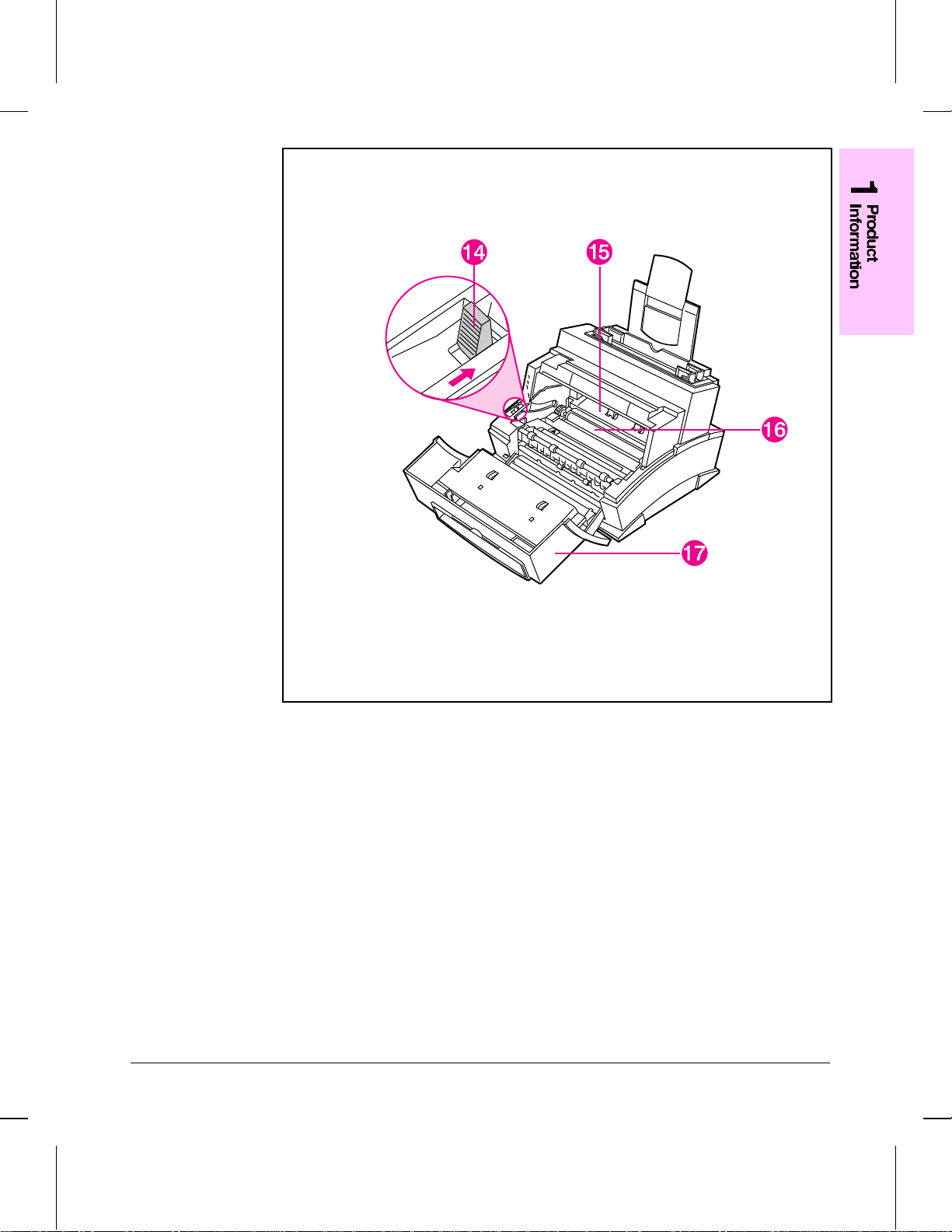
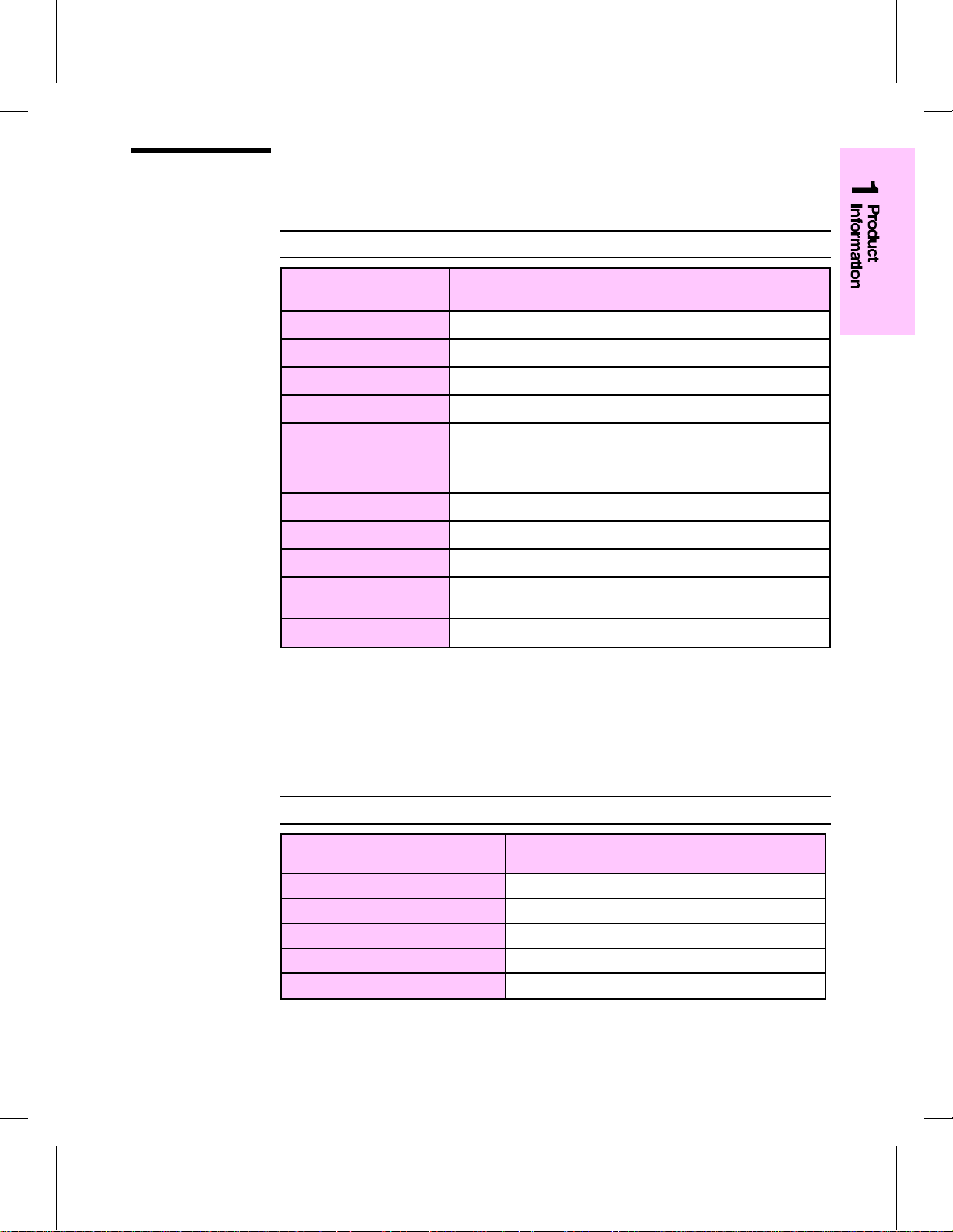
Figure 1-3
Front Door Assemblies
14. Paper Release Lever 16. Transfer Roller
15. Toner Cartridge Compartment 17. EP Door
Product Information 1-7
Page 16

Figure 1-4 I
Back View of the Printer
18. Power Cable Connector 20. Memory Expansion Cover
19. Parallel Cable Connector
1-8 Product Information
Page 17

Service Appr oach
Repair of the printer normally begins with the use of the printer’ s internal
diagnostics in conjunction with the troubleshooting procedures in Chapter 7. Once a
faulty part is located, repair is generally accomplished by assembly level
replacement of Field Replaceable Units (FRUs). Some mechanical assemblies may
be repaired at the subassembly level. PCA component replacement is not supported
by Hewlett-Packard. Part numbers for all FRUs are located in Chapter 8 of this
manual.
Parts Exchange Program
HP offers remanufactured assembles for some selected parts. These are identified in
Chapter 8 and can be ordered through HP’s P arts Direct Ordering, or Parts Center
Europe (PCE).
Ordering Parts
Field replaceable part numbers are found in Chapter 8 of this manual. Replacement
parts may be ordered from HP’s Service Materials Organization (SMO Parts Direct
Ordering), or Support Materials Europe (SME).
Ordering Consumables
The printer has no consumables other than the toner cartridge, which may be
ordered directly from Hewlett-Packard. Refer to Chapter 8 for ordering information.
Ordering Related Documentation
Table 1-6 on the following page lists part numbers and where to order related
documentation. Phone numbers for the various sources are:
•• PDO (Parts Direct Ordering)
1-800-227-8164 (U.S. only)
•• HP’s Distribution Center (HPD)
970-339-7009 (U.S. only)
•• SME
Product Information 1-9
Page 18
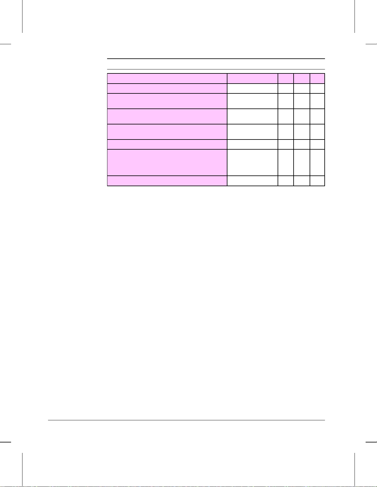
Table 1-6 Related Documentation
Description Part Number SMO SME HPD
HP LaserJet Family Quick Reference Service Guide 5010-3991 X X
HP LaserJet 5L Printer
User’s Manual
HP PCL5 Printer Language Technical
Reference Information Package
HP LaserJet Printer Family Paper
Specifications
LaserJet Basic Hardware Training Course 5961-0880 X X
HPLJ 5L Hardware Training Kit C3941+49A-60001
Specific Application Drivers X
Guide
Print Utilities
HP provides several utilities for enhancing use of the LaserJet printers in MS-DOS
and Windows environments. More information on specific utilities is included with
each of the drivers listed in Table 1-6.
C3941-90901 X
5010-3994 X X
5010-3990 X X X
(NTSC)
C3941+49A-60002
(PAL)
X
XX
1-10 Product Information
Page 19

Technical Assistance
HP ASAP
HP ASAP (Automated Support Access Program) provides free user technical
support information 24 hours a day, 7 days a week. The ASAP system includes HP
AUDIO-TIPS and HP FIRST, both explained below. The ASAP service requires a
touchtone phone.
HP A UDIO-TIPS
HP AUDIO-TIPS is an interactive voice response system providing prerecorded
answers to the most frequently asked questions by HP LaserJet printer users.
Helpful “System Maps” to the HP AUDIO-TIPS recordings are a vailable by fax
through HP FIRST.
HP FIRST
HP FIRST (Fax Information Retrieval Support Technology) is a phone-in fax
service providing technical information for HP LaserJet users as well as service
personnel. Receiving a fax requires a group-3 facsimile machine or fax card.
Service related information includes:
•• Service Notes (HP Authorized dealers)
•• Application Notes
•• Product Data Sheets
•• Material Safety Data Sheets (MSDS)
•• Typeface and accessory information
•• Printer support software information
•• Toner information
•• Driver request form and Software Matrix.
HP FIRST (U.S. only)
Call the HP ASAP system (1-800-333-1917) and follow the voice prompts to enter
HP FIRST.
HP CompuServe Forum
CompuServe members can download a variety of support materials including
product data sheets, software application notes, and printer drivers for many popular
software applications. Members may also post and reply to questions in an
interactive format. To access the HP Forum, type GO HP at any prompt. For more
information, or to join CompuServe, call 1-800-524-3388.
Product Information 1-11
Page 20

Customer Information Centers (North America Only)
For presales information, contact the nearest Hewlett-Packard Customer
Information Center, 1-800-752-0900 in North America.
Customer Support Center (Assist Line)
The HP Customer Support Center, (208-323-2551) is available to answer technical
questions regarding setup, configuration, installation, and operation of HP printers
in the PC and Macintosh environments. The CSC Assist line is av ailable weekdays
from 6 AM to 6 PM and Saturdays 9 AM to 4 PM Mountain Time.
Questions relating to operating systems such as MS-DOS and UNIX, your network
configuration, or network operating system cannot be answered by the Center and
should be referred to your authorized reseller.
North American Response Center
The North American Response Center (NARC) is available for technical support to
assist service technicians. The NARC can be reached at 1-800-544-9976. To access
this service, HP resellers must have a valid CZ number.
1-12 Product Information
Page 21

Warranty
This warranty gives you specific legal rights. You may also have other rights, which
may vary from area to area.
Hewlett-Packard warrants the 5L LaserJet printer against defects in materials and
workmanship for a period of one year from the date of purchase by the end user and
is not transferable.
During the warranty period, Hewlett-Packard will, at its option, either repair or
replace hardware products that prove to be defective.
Should Hewlett-Packard be unable to repair or replace the product within a
reasonable amount of time, a refund of the purchase price may be made upon return
of the product. To have your printer serviced by Hewlett-Packard, you must make
arrangements to have it serviced in the country of purchase.
Warranty Exclusions
The warranty on your HP LaserJet printer shall not apply to defects or damage
resulting from:
•• Improper or inadequate maintenance by customer.
•• Customer-supplied software or interfacing.
•• Unauthorized modification or misuse.
•• Operation outside of the environmental specifications for the product.
•• Operation of nonsupported printing media.
•• Duty cycle abuse (see later explanation).
•• Operating the printer from a mechanical switchbox without a designated surge
protector.
•• Improper site preparation and maintenance.
•• Use of non-HP toner cartridges (see explanation) or DRAM (JEDIA) memory
cards.
The use of non-Hewlett-Packard toner cartridges does not affect either the warranty
or any maintenance contract purchased from Hewlett-Packard. However, if an HP
LaserJet printer failure or printer damage is found to be directly attributable to the
use of any non-HP product, the repair will not be covered under the warranty or HP
maintenance contract. Hewlett-Packard cannot recommend use of non-HP toner
cartridges, either new or remanufactured, because they are not HP products and
Hewlett-Packard cannot influence or control their quality.
Operation of the printer beyond the limit of its duty cycle (printing more than the
equivalent of 4,000 single-sided pages per month) shall be deemed printer abuse
and all repairs thereafter will be billed on a time and materials basis.
Product Information 1-13
Page 22

If you are using a mechanical switchbox, ensure that it is equipped with a surge
protector. Damage to your printer could occur from the use of unprotected
mechanical switchboxes.
The warranty period begins either on the date of delivery or, where the purchase
price includes installation by Hewlett-Packard, on the date of installation.
Warranty Limitations
The warranty set forth above is exclusi ve and no other warranty, whether written or
oral, is expressed or implied. Hewlett-Packard specifically disclaims the implied
warranties of merchantability and fitness for a particular purpose.
Some areas do not allow limitations on how long an implied warranty lasts, so the
preceding limitation or exclusion may not apply to you. Howe ver, any implied
warranty of merchantability or fitness is limited to the one-year duration of this
written warranty.
In no event will Hewlett-Packard or its suppliers be liable to you for any
consequential or incidental damages, including any lost profits or lost savings, or
for any claim by any party, even if a representative of HP or its suppliers has been
advised of the possibility of such damages.
Some areas, states, or provinces do not allow the exclusion or limitation of
incidental or consequential damages, so the preceding limitation or exclusion may
not apply to you.
Voltage Conversions
HP LaserJet printers are manufactured to different specifications for different
countries. Because of these differences, HP does not recommend transporting
products sold within one country to another country.
In addition to the 115-220 voltage environment concerns, the country of final
destination may have different import and export restrictions, power frequencies,
and regulatory requirements.
Note
1-14 Product Information
The HP LaserJet family printers must be serviced by an authorized repair depot or
reseller within the country where the printer was originally purchased.
Because of the different specifications and warranty coverage limitations,
Hewlett-Packard does not offer a conversion, or support the conversion, of HP
LaserJet family printers. We advise those customers planning to transport
equipment to different countries to purchase the products in the country of final
destination.
Page 23

Site Requirements
Contents
Site Requirements . . . . . . . . . . . . . . . . . . . . . . . . . . . . . . . 2-3
Operating Environment . . . . . . . . . . . . . . . . . . . . . . . . . . . 2-3
Printer Space Requirements . . . . . . . . . . . . . . . . . . . . . . . . . . 2-4
The HP C3906A Toner Cartridge . . . . . . . . . . . . . . . . . . . . . . . 2-5
Storage Conditions . . . . . . . . . . . . . . . . . . . . . . . . . . . . . 2-5
Storing Opened Toner Cartridges . . . . . . . . . . . . . . . . . . . . . . 2-5
Toner Cartridge Handling Suggestions . . . . . . . . . . . . . . . . . . . 2-5
2
Site Requirements 2 -1
Page 24

2 -2 Site Requirements
Page 25

Site Requirements
Operating Environment
The environmental requirements listed in the table below must be maintained to
ensure the proper operation of this printer.
Table 2-1 Environmental Requirements
LaserJet 5L & Cartridge Operating Storage
Temperature 50 to 90.5° F (10 to 32.5° C) 32 to 104° F (0 to 40° C)
Humidity 20 to 80% RH
(with no condensation)
Consider the following points before installing the printer:
10 to 80% RH
(with no condensation)
•• Install in a well-ventilated, dust-free area.
•• Install on a hard, flat and continuous surface, with all four printer feet level. Do
not install on carpet or other soft surfaces.
•• Ensure adequate power is supplied. Printer power requirements are listed under
“Specifications,” in Chapter 1.
•• Install away from direct sunlight, open flames, or ammonia fumes. If the printer
is placed near a window, make sure the window has a curtain or blind to block any
direct sunlight.
•• Install with enough space around the printer for proper access and ventilation.
(See Figure 2-1.)
•• Install printer away from the direct flow of exhaust from air ventilation systems.
Site Requirements 2 -3
Page 26

Figure 2-1
Printer Space Requirements
Printer Space Requirements
Table 2-2 Printer Dimensions
Width 13.2 in. (335.5 mm)
Depth 12.3 in. (311.2 mm)
Height (storage)
(operational)
Weight (with toner cartridge) 15.9 lbs. (7.2 kg)
Toner cartridge weight** 1.5 lbs. (.7 kg)
* With letter input assembly extended.
** Some quantity of toner will reside in the waste toner area of a toner cartridge when the toner
supply is exhausted. Therefore, using toner cartridge weight may be an unreliable indication of
remaining toner supply.
2 -4 Site Requirements
Description Dimension
8.9 in. (227.5 mm)
14.6 in. (372.7 mm)*
Page 27

The HP C3906A Toner Cartridge
Toner cartridges contain components that are sensitive to light, temperature, and
humidity . Follow the recommendations in this section to ensure the highest quality
and longest life of HP toner cartridges.
Keep the printer within the following environmental conditions for optimum
performance.
Storage Conditions
The toner cartridge is affected by its environment. Packaging protects the toner
cartridge from light and increases its storage life. It is important to store the
cartridge in its original packaging until the cartridge is ready to be installed in the
printer.
When storing the toner cartridge in a warehouse or work area, make sure the storage
place meets the conditions specified in Table 2-1.
Storing Opened Toner Cartridges
Because the cartridge does not have a shutter to cover the laser beam access slot, it
should be kept inside the printer until empty. Toner cartridges which ha ve had the
toner sealing tape removed are also more vulnerable to environmental extremes
(such as high humidity).
Caution
If the toner cartridge must be removed from the printer, al ways store the cartridge:
•• Inside the protective bag in which it was originally packaged.
•• In a dark cabinet, away from direct sunlight.
•• Correct side up and in a horizontal position (not standing on end).
•• At a temperature between 32° to 104° F (0° and 40° C) .
•• Away from ammonia or other organic solvent fumes.
Never ship the printer with a toner cartridge installed. Excessive vibration during
shipping can cause toner to leak, contaminating the printer. Never expose the toner
cartridge to direct sunlight or to room light for more than a few minutes. Bright
light and direct sunlight can permanently damage a toner cartridge.
Site Requirements 2 -5
Page 28
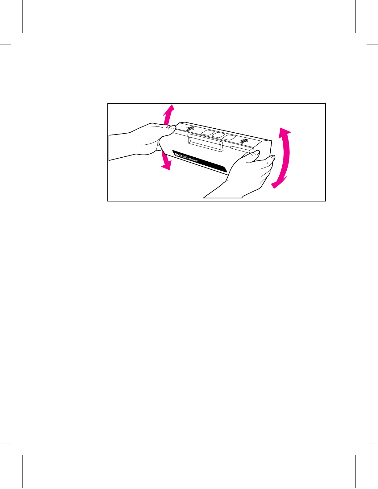
Figure 2-2
Toner Cartridge Handling Suggestions
•• Before installing a cartridge, distribute the toner evenly by rotating the cartridge
back and forth five to six times. (See Figure 2-2.) Repeat this action when toner
begins to run low.
TonerCartridge C3906A
Toner Cartridge Distribution
•• Do not touch the surface of the photosensitive drum in the cartridge. Protect the
drum from light and contamination.
•• Do not expose the cartridge to unnecessary vibrations or shock.
•• Do not expose the photosensitive drum to strong light. White areas on the page may
indicate that the drum has been exposed to light for too long. If white areas appear,
stop the printer and wait a few minutes. This process should eliminate most
defective images. If not, the toner may be placed in a dark environment for an
extended period of time, which may restore some life to the drum.
•• Never manually rotate the drum, especially in the reverse directions; internal
damage and toner spills may result.
•• Do not install the toner cartridge in the printer for shipping.
2 -6 Site Requirements
Page 29

Installation and Configuration
Contents
Unpacking and Installation . . . . . . . . . . . . . . . . . . . . . . . . . . . 3-3
Step 1: Choose the best location . . . . . . . . . . . . . . . . . . . . . . 3-3
Step 2: Unpack the printer . . . . . . . . . . . . . . . . . . . . . . . . . 3-3
Step 3: Check package contents . . . . . . . . . . . . . . . . . . . . . . 3-3
Step 4: Install the toner cartridge . . . . . . . . . . . . . . . . . . . . . . 3-4
Step 5: Load paper . . . . . . . . . . . . . . . . . . . . . . . . . . . . . 3-4
Step 6: Attach the power cord . . . . . . . . . . . . . . . . . . . . . . . 3-4
Step 7: Install printing software . . . . . . . . . . . . . . . . . . . . . . 3-4
Host-Based Printer Driver . . . . . . . . . . . . . . . . . . . . . . . . . . 3-5
Host-Based Printer Settings . . . . . . . . . . . . . . . . . . . . . . . . . 3-6
PCL Printer Driver . . . . . . . . . . . . . . . . . . . . . . . . . . . . . 3-7
Using Host-Based and PCL Drivers Together . . . . . . . . . . . . . . . 3-9
Using the Control Panel . . . . . . . . . . . . . . . . . . . . . . . . . . . . 3-10
Control Panel Layout . . . . . . . . . . . . . . . . . . . . . . . . . . . . 3-10
LED Lights . . . . . . . . . . . . . . . . . . . . . . . . . . . . . . . . . 3-11
The Front Panel Button . . . . . . . . . . . . . . . . . . . . . . . . . . . 3-13
Printing a Self-Test Page . . . . . . . . . . . . . . . . . . . . . . . . . . . . 3-14
Continuous Self Test . . . . . . . . . . . . . . . . . . . . . . . . . . . . 3-15
Printing an Engine Test . . . . . . . . . . . . . . . . . . . . . . . . . . . . 3-16
Resetting the Printer . . . . . . . . . . . . . . . . . . . . . . . . . . . . . . 3-17
To Reset the Printer . . . . . . . . . . . . . . . . . . . . . . . . . . . . . 3-17
3
Installation and Configuration 3-1
Page 30

3-2 Installation and Configuration
Page 31

Unpacking and Installation
Before unpacking the printer, inspect the shipping container for signs of physical
damage. Since a damaged shipping box is an indication of improper handling
during shipping, the printer may also be damaged.
Note
Note
If the shipping container has any sign of damage, unpack the printer and plug it in
with the carrier’s agent present. If the printer appears damaged or f ails a self test, do
not accept it. (See “Printing a Self-Test Page” later in this chapter.)
Step 1: Choose the best location
Verify that the printer location meets all requirements listed in Chapter 2.
Step 2: Unpack the printer
1 Remove the power cord, manual, and the toner package.
2 Remove the printer from its box.
3 Remove the outer packaging material from the printer.
4 Open the EP Door.
Step 3: Check package contents
If any of the package contents are missing or damaged, contact your HP dealer
immediately .
The package should include the following:
•• Printer
•• Power cord
•• Software
•• Disk 1, Intelligent Installer, Host-based software, Host-based status window
•• Disk 2, True-Type Screen Fonts (21 fonts)
•• Disk 3, PCL Driver, PCL status window
•• Disk 4, DOS utilities (DOS Status Monitor, Lotus, and WordPerfect Drivers)
•• User’s Manual
•• Toner cartridge
Installation and Configuration 3-3
Page 32

Step 4: Install the toner cartridge
1 Open the EP Cartridge door.
2 Remove toner cartridge from its box and cut it open. Save the packing materials for
possible cartridge storage.
3 Shake the cartridge vigorously to distribute the toner evenly inside the cartridge.
(See Figure 2-2.)
4 Grasp the toner sealing tab on the right side of the cartridge. Pull firmly to remove
the strip of sealing tape.
5 Grasp the plastic cartridge body and slide the cartridge into the printer, pushing it
firmly into place. Close the EP Cartridge door.
Step 5: Load paper
1 Insert paper into the Input Paper Bin.
2 Adjust paper guides to fit the width of the paper snugly. This avoids paper skewing.
Step 6: Attach the power cord
1 Connect the power cord at the right rear of the the printer. (Since there is not a
power switch, plugging in the power cord is the only method to power the printer on
and off.) All of the Control Panel lights briefly illuminate, then the green Ready
light comes on.
2 Briefly press the Front Panel Button to generate a self test and verify that the printer
is working.
Note
Refer to the section “Printing a Self -Test Page,” later in this chapter, for a detailed
description of self-test information.
Step 7: Install printing software
The printing software package supplied with the HP LaserJet 5L printer provides
many useful programs and utilities. With this software, you can:
•• Select paper size and orientation.
•• Select the number of copies you would like to print.
•• Adjust printing resolution, brightness, and contrast.
•• Learn tips and techniques for using this software.
This software allows you to install two types of printer drivers: a host-based driver
and a PCL driver. If your system meets the minimum requirements, the host-based
software will be installed automatically.
3-4 Installation and Configuration
Page 33

Note
If your system does not meet these minimum requirements, only the PCL driver
software will be installed.
Minimum System Requirements
•• 486 or above PC with 8 Mbytes DRAM (minimum)
•• Fully functional bi-directional cable (IEEE 1284-compliant cable recommended)
•• HP LaserJet 5L printer connected and powered on
To install the printing software
1 Turn on your computer.
2 Start Microsoft Windows and install Disk 1 into your disk dri v e A.
3 From Program Manager, select File.
4 From the File menu, choose Run.
5 Type A:\setup.
6 Press ENTER or click OK. The setup program will begin.
7 Follow the instructions as they appear on the screen.
During installation, a dialog box will appear that asks whether you would like a
typical or custom installation. If you select typical, the installer automatically
selects and installs the appropriate driver, depending on your system. If you select
custom, a dialog box will ask you which driver and what components you would
like to install.
As part of the installation process, the software creates groups within Program
Manager for the driver that was installed. You will find a group entitled either HP
LaserJet 5L Printer or HP LaserJet 5L PCL Printer, depending upon which dri ver
was installed.
To Verify Printer Drivers
If you have installed multiple printer driv ers, you may want to verify which printer
driver you are currently running. To verify your printer driver from Program
Manager, select Control Panel, Printer s, Setup, About.
Host-Based Printer Driver
The host-based software included with the HP LaserJet 5L is a single application
that combines the functions of a printer driver, printer formatter, and status window.
This software uses your PC’s resources, rather than the printer’s resources, to
process printer data. Your PC converts data into raster scan line data and sends the
raster data to the printer. This process happens real-time, which speeds up the
printing process.
Installation and Configuration 3-5
Page 34

Figure 3-1
If you would like to connect another device to the LPT port you have configured to
use with the HP LaserJet 5L, select the other device from the Microsoft Windows
Control Panel and restart windows.
The HP LaserJet printer is capable of receiving and processing both PCL
commands and host-based generated data.
Host-Based Printer Settings
To select printer settings, open the HP LaserJet 5L Printer group within Program
Manager and select HP 5L Driver Settings. The Printer Settings window will
appear. (See Figure 3-1.) Select from the following options:
•• Paper—Select Page Orientation, number of Copies, Scaling, Paper Size, and
Manual Feed.
•• Print Quality—Select Printer Resolution, Economode, or Advanced. Within
Advanced, set Resolution Enhancement, Toner Density, Brightness, and Contrast.
•• Tips—Review quick tips and techniques for using this software.
You can also select the About button from the main screen. From the About screen,
select System Info... to create a host-based test page that contains all of the system
parameters. This test page will be saved as “HPWTSTPG.TXT.”
Host-Based Printer Settings Options
Note
3-6 Installation and Configuration
Some applications (e.g., Microsoft Word and CorelDRAW!) allow you to change
your printer settings by selecting Print Setup and selecting the Setup option. If you
choose to change your printer settings from your application, the HP window will
appear, just as it would from Program Manager.
Page 35

Figure 3-2
Host-Based Printing Status
To view your printer’s status, open the HP LaserJet 5L Printer group within
Program Manager and select Status Window. As shown in Figure 3-2 below, the
status window reports your printer’s current status. In this case, the printer is Ready.
Host-Based Printing Status
This host-based status window is only compatible with the HP LaserJet 5L. If you
have loaded both the host-based and PCL software, both cannot be active for the HP
LaserJet 5L at the same time, even though both software programs have their own,
unique status windows. (See “Using Host-Based and PCL Drivers Together” later in
this chapter.)
PCL Printer Driver
This printer driver has been updated from the HP Laser Jet 5P version 1.0 printer
driver. This software is compatible with the HP LaserJet 4 family drivers.
Installation and Configuration 3-7
Page 36

Figure 3-3
PCL Printer Settings
To change printer settings, select Control Panel, Printers, HP LaserJet 5L (PCL),
Setup. The printer settings window will appear. (See Figure 3-3.) Select from the
following options:
•• Paper—Select Paper Size, Paper Source (manual feed), Copies, Orientation
(portrait or landscape), and Set Custom Paper Size.
•• Print Quality—Select Print Optimization Settings and Economode.
•• Fonts—Choose to run the HP Font Installer and to add True Type Fonts.
•• Device Options—Select Enhanced I/O, Installed Memory, and Resolution
Enhancement technology.
PCL Printer Settings Options
3-8 Installation and Configuration
Page 37

Figure 3-4
PCL Printing Status
To view your printer’s status, open the HP LaserJet 5L PCL Printer group within
Program Manager and select Status Window. As shown in Figure 3-4 below, the
status window reports your printer’s current status. In this case, the printer is Ready.
PCL Printing Status
As with the host-based software, the PCL software has its own, unique status
window, but both windows cannot be active at the same time. To use both drivers,
see “Using Host-Based and PCL Drivers Together” below.
Using Host-Based and PCL Drivers Together
Occasionally conflicts may arise between the host-based and PCL drivers’ status
windows, and an error message may appear. Should this occur, you can disable one
of the drivers using one of the following three methods:
•• Turn off the PCL software status window by selecting Device Options, No Status
from the PCL Printer Settings window.
•• Remove either the PCL or host-based software by selecting Main, Control Panel,
Printers from Program Manager and then deleting the printer driver.
•• Select HP 5L Uninstall from the HP LaserJet 5L Printer Group in Program
Manager.
Installation and Configuration 3-9
Page 38

Using the Control Panel
Control Panel Layout
The Control Panel consists of three status lights and a Front Panel Button located at
the front of the printer.
The Control Panel consists of one button and three status lights.
ERROR (Yellow)
DA T A (Green)
READY (Green)
These lights can be in only one of the following states:
OFF ON Blinking
3-10 Installation and Configuration
Page 39

LED Lights
The LED lights provide a quick way to check the printer’s status.
Table 3-1 Indicator Lights (1 of 2)
When this Indicator: Looks like
this:
On
Blinking
On Form Feed There is unprinted
Blinking Manual Feed The printer is in
On Error (light continuously on)
It means this: Do this:
Ready Ready to print.
Print job in progress. Let job finish printing.
data in the buffer.
manual feed mode.
Printer is out of paper.
Printer’s EP door is open.
Toner cartridge is either missing
or not installed correctly.
Briefly press the Front Panel Button to print the
remaining data.
Make sure you have the correct paper in the
Single Sheet Input Bin, and briefly press and
release the Front Panel Button to print.
Add paper.
Close the door.
Install a cartridge, being careful to position it
correctly.
There is paper jammed in the
printer.
Clear the jam and resume printing.
If the Error light remains lit after checking for
these problems, and there’s no paper jam,
disconnect the power for 10 seconds, then
reconnect to the power source. If, after taking
these actions, the light remains on, refer to
Chapter 7, “Troubleshooting."
Installation and Configuration 3-11
Page 40

Table 3-1 Indicator Lights (Continued 2 of 2)
When this indicator: Looks like
this:
Blinking Error (light blinking) Page T oo
All off Sleep Mode Either the printer is
All on Hardware Error There is an
It means this: Do this:
Complex
The page may be too complex
for the printer’s memory capacity
or the printer may not be able to
create the image fast enough to
keep pace with the engine
printing process.
in SleepMode or the power
source has been disabled.
internal problem that won’t allow
printing.
Briefly press and release the Front Panel Button
to continue printing. There may be some data
loss on the page.
Hint: To avoid this in the future:
1. See your printer driver help for more
suggestions regarding printer memory usage.
2. Reduce resolution to 300 dpi with your
software.
3. Install additional printer memory. (See chapter
6 for information on installing additional memory.)
No action is necessary. When you press the
Front Panel Button, send data to the printer, or
open the printer door, the status light comes on.
1. If you have added an additional memory card,
try removing it.
2. Disconnect the power for 10 seconds, then
reconnect it.
3. If all of the lights come on steadily again, try
disconnecting the power for 15 minutes.
All Blinking Memory Error An incompatible
3-12 Installation and Configuration
memory card has been installed.
If this error remains after completing the tasks
above, see Chapter 7, “Troubleshooting."
HP LaserJet 5L User’s Manual
See the
appendix D, for memory card specifications. The
memory card must be a 70 nsec or faster card.
,
Page 41

The Front Panel Button
Depending on what state the printer is in, pressing the Front Panel Button allows
you to control printing tasks by either starting or resuming a printer function. Use
the Front Panel Button to accomplish the following tasks:
Table 3-2 Front Panel Button Usage
Function Action Lights Result
Wake Up Briefly push and release the
button.
All lights are off while
plugged into power source.
The printer will wake up to a
ready state.
Self Test Briefly push and release the
Printer Reset Press and hold the button
Resume (from
Manual Feed)
Continue (from
memory error)
Form Feed Briefly push and release the
button.
until the three Front Panel
Lights blink quickly in
succession.
Briefly push and release the
button.
Briefly push and release the
button.
button.
Ready (bottom) light is on
and the other lights are off.
The Ready (bottom) Light
will remain lit, if there are no
printer errors.
The Data (middle) Light
blinks.
Error (top) light blinks. Allows the printer to recover and
The Data (middle) Light and
the Ready (bottom) Light
both remain on.
Prints a self-test page.
The reset will return the printer to
the factory default settings. This
clears all data from memory,
including any downloaded fonts
and macros.
Override manual feed to print
from paper cassette.
continue printing the job.
The remaining data in printer
memory will print.
Installation and Configuration 3-13
Page 42
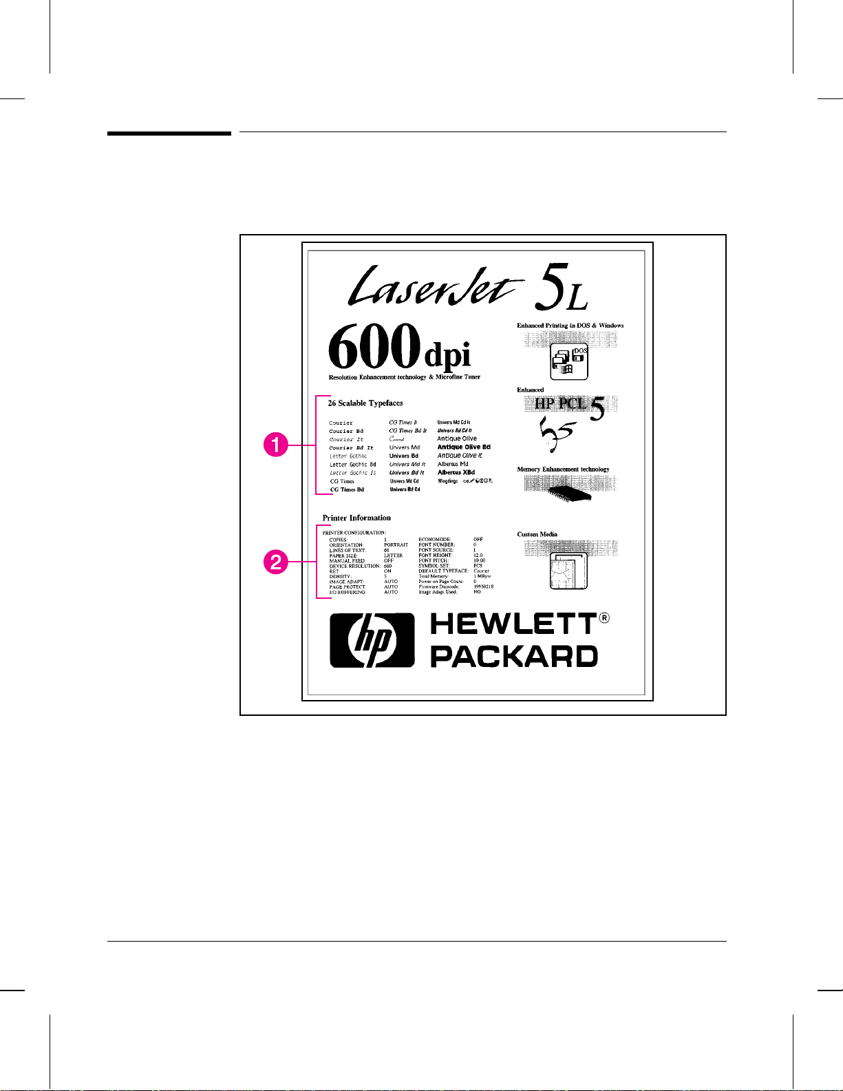
Figure 3-5
Printing a Self-Test Page
A self-test page can be useful in troubleshooting printer problems and determining
which fonts have been downloaded to the printer.
Self-test Page
The self-test page includes an internal font listing showing all 26 provided fonts (1)
and a listing of the current printer configuration (2). (If any fonts have been
downloaded to the printer a second page will print.)
To print a self-test page:
1 Make sure the Ready (bottom) Light is on, and all other lights are off. Wake up the
printer if necessary by pressing the Front Panel Button.
2 Briefly press and release the Front Panel Button. The Data (middle) Light comes
on, the Ready (bottom) Light blinks. Wait for a self-test page to print.
3-14 Installation and Configuration
Page 43

Continuous Self Test
A continuous self test can be useful for troubleshooting paper path and other
problems. To print a continuous self test:
1 Disconnect the printer from the power source.
2 Press and hold down the Front Panel Button while connecting power.
3 Continue holding the button for about five seconds.
All lights will illuminate at once, then each will light in sequence.
4 Release the button. The printer conducts its internal diagnostics routine, then prints
the self-test page continuously until stopped.
5 To stop the continuous self test (and reset the printer), press and hold the Front
Panel Button for a few seconds until all lights begin lighting in sequence once again.
Note
The self test does not print at the printer’s rated speed of four pages per minute.
Installation and Configuration 3-15
Page 44

Printing an Engine Test
The engine test print can be used to verify that the print engine is functioning
correctly . The Formatter PCA is completely bypassed during an engine test.
Consequently , this test is useful for isolating engine printer problems. The engine
test prints a full page of vertical lines down the entire printable area. This page is
useful for checking and adjusting registration.
Note
Figure 3-6
Perform the engine test with the printer covers in place, as shown in Figure 3-6.
Refer to “Engine Test” in Chapter 7 for the engine test procedure.
Engine Test Button
3-16 Installation and Configuration
Page 45

Resetting the Printer
Resetting the printer accomplishes the following:
•• Clears all data from the printer’s memory (including unprinted data, downloaded
fonts, and macros).
•• Stops any printing that is taking place and ejects the page.
•• Removes some error conditions.
•• Resets the printer to its factory default settings.
To Reset the Printer
Press and hold the Front Panel Button until the three control panel lights blink
quickly in succession (about 5 seconds), then let go of the button. After resetting,
the Ready (bottom) Light will remain lit if there are no printer errors. (Make sure
there is paper in the printer or the error light will remain on.)
Installation and Configuration 3-17
Page 46

3-18 Installation and Configuration
Page 47

Printer Maintenance
Contents
Life Expectancy of Consumables . . . . . . . . . . . . . . . . . . . . . . . 4-3
Toner Cartridge Life . . . . . . . . . . . . . . . . . . . . . . . . . . . . . . 4-4
Saving Toner with EconoMode . . . . . . . . . . . . . . . . . . . . . . 4-4
Refilled Toner Cartridges . . . . . . . . . . . . . . . . . . . . . . . . . . 4-5
Recycling Toner Cartridges . . . . . . . . . . . . . . . . . . . . . . . . . 4-5
Cleaning the Printer . . . . . . . . . . . . . . . . . . . . . . . . . . . . . . 4-6
Cleaning Printer Components . . . . . . . . . . . . . . . . . . . . . . . . 4-7
Cleaning Spilled Toner . . . . . . . . . . . . . . . . . . . . . . . . . . . 4-8
4
Printer Maintenance 4-1
Page 48

4-2 Printer Maintenance
Page 49

Life Expectancy of Consumables
Always inspect the components listed in Table 4-1 for wear when servicing the
printer. Replace these components as needed, based on printer failures or wear, not
strictly on usage.
Table 4-1 Life Expectancy of Consumables
Description Part No. Est Life
Toner Cartridge
(user replaceable)
Transfer Roller RF5-1534-000CN 50,000 May affect print quality
Paper Pickup Assembly RG5-1940-000CN 50,000 Look for glazing and/or
Separation Pad &
Sub pads
Heating Element
100-120 V, 50/60 Hz
(exchange part no.)
220-240 V, 50 Hz
(exchange part no.)
Pressure Roller
*
The estimated toner cartridge life is based on Letter or A4 size paper with an average of 5% toner
coverage and a medium density setting. Toner cartridge life can be extended further by conserving
toner using the printer’s EconoMode feature.
C3906A 2,500* When print becomes faint,
RB1-5008-000CN 50,000 May affect paper movement.
RG5-1964-000CN
RG5-1965-000CN
RF5-1516-000CN
(pgs)
50,000
shake cartridge to distribute
remaining toner.
and/or paper movement.
cracks.
May affect print quality
and/or paper movement.
Look for marks on pressure
roller or upper Teflon sleeve.
Remarks
Printer Maintenance 4-3
Page 50

Figure 4-1
Toner Cartridge Life
The toner cartridge has been designed to simplify the replacement of the printer’s
major “consumable” parts. The toner cartridge contains the printing mechanism and
a supply of toner. When using a typical word-processing application, a toner
cartridge will print approximately 2500 pages where the text covers about 5% of the
page.
Five Percent Text Coverage
When regularly printing pages with less coverage, such as short memos, a toner
cartridge should print over 2500 pages. However, if routinely printing very dense
print, the cartridge will not print a full 2500 pages.
Note
For best results, always use a toner cartridge before the expiration date stamped on
the toner cartridge box.
Saving Toner with EconoMode
Toner cartridge life can be extended dramatically by using the EconoMode printing
feature of the printer. EconoMode uses approximately 50% less toner than normal
printing. The printed page is much lighter and is adequate for printing drafts or
4-4 Printer Maintenance
Page 51

proofs. EconoMode can be set through your printer driver. See Chapter 3 for
information.
Notes
Some software applications may refer to this as “draft mode."
Refilled Toner Cartridges
While Hewlett-Packard does not prohibit the use of refilled toner cartridges during
the warranty period or while under a maintenance contract, we do not recommend
their use. The reasons for this are:
•• Hewlett-Packard has no control or process to ensure that a refilled toner cartridge
functions at the high level of reliability of a new HP LaserJet toner cartridge.
•• Hewlett-Packard also cannot predict what the long-term reliability effect on the
printer is from using different toner formulations found in refilled cartridges.
•• Hewlett-Packard has no control over the actual print quality of a refilled toner
cartridge. The print quality of HP LaserJet toner cartridges influences the
customer’s perception of the printer.
Repairs resulting from the use of refilled toner cartridges are not covered under the
HP warranty or maintenance contract.
Recycling Toner Cartridges
In order to reduce waste, Hewlett-Packard has adopted a recycling program for used
toner cartridges. Plastics and other material are recycled. Cartridge components that
do not wear out are reused. HP pays the shipping costs from the user to the
recycling plant. For each cartridge returned, HP donates one U.S. dollar to be
shared by the Nature Conservancy and the National Wildlife Federation. To join this
recycling effort, follow the instructions inside the toner cartridge box.
Printer Maintenance 4-5
Page 52

Cleaning the Printer
To maintain the print quality, thoroughly clean the printer:
•• Every time you change the toner cartridge.
•• After printing approximately 2,500 pages.
•• Whenever print quality problems occur.
Clean the outside of the printer with a lightly water-dampened cloth. Clean the
inside with only a dry, lint-free cloth. Observe the warnings and cautions below.
WARNING!
Before you begin these steps, unplug the printer to avoid shock hazard.
When cleaning around the front door area, avoid touching the heating element. It
may be HOT. (For heating element location, see Figure 6-14.)
4-6 Printer Maintenance
Page 53

Cleaning Printer Components
CAUTION
To avoid permanent damage to the toner cartridge, do not use ammonia-based
cleaners on or around the printer. Do not touch the transfer roller with your fingers.
Contaminants on the roller can cause print quality problems.
Table 4-2 Cleaning Printer Components
COMPONENT CLEANING METHOD/NOTES
Outside Covers Use a water-dampened cloth. Do not use solvents or
Inside General Use a dry, lint free cloth. Remove all dust, spilled toner, and
Exit Roller Use a water-dampened lint-free cloth. (For location, see
Fuser Exit Roller Use a water-dampened lint-free cloth. (For location, see
Pressure Roller Use a dry lint-free cloth. (For location, see Figure 6-16.)
Transfer Roller Use a dry, lint-free cloth. DO NOT TOUCH with y our fingers.
Separation Pad Use a dry lint-free cloth. (For location, see Figure 6-33.)
Delivery Assembly Use a water-dampened lint-free cloth. (For location, see
Static Eliminator Teeth Use compressed air. (See Figure 4-2 on the following page
ammonia-based cleaners.
paper particles.
Figure 6-8.)
Figure 6-18.)
(For location, see Figure 6-30.)
Figure 6-10.)
for static eliminator teeth location.)
Printer Maintenance 4-7
Page 54

Figure 4-2
Static Eliminator Teeth (located in front of the transfer roller)
Note
Cleaning Spilled Toner
Defective toner cartridges can develop leaks. In addition, after a paper jam has
occurred, there may be some toner remaining on the rollers and guides inside the
printer. The pages that print immediately after the jam may pick up this toner.
Clean spilled toner with a cloth slightly dampened in cold water. Do not touch the
Transfer Roller with the damp cloth or with your fingers. Do not use a vacuum
cleaner unless it is equipped with a micro-fine particle filter.
If toner gets on your clothing, use cold water to remove it. Hot water sets toner
stains into fabric.
4-8 Printer Maintenance
Page 55

Functional Overview
Contents
Basic Printer Functions . . . . . . . . . . . . . . . . . . . . . . . . . . . . . 5-3
DC Controller/Power System . . . . . . . . . . . . . . . . . . . . . . . . . 5-4
Print Engine Control System . . . . . . . . . . . . . . . . . . . . . . . . 5-5
Power System (on DC Controller PCA) . . . . . . . . . . . . . . . . . . 5-6
Formatter System . . . . . . . . . . . . . . . . . . . . . . . . . . . . . . . . 5-8
CPU . . . . . . . . . . . . . . . . . . . . . . . . . . . . . . . . . . . . . 5-8
Read Only Memory (ROM) . . . . . . . . . . . . . . . . . . . . . . . . . 5-8
Random Access Memory (RAM) . . . . . . . . . . . . . . . . . . . . . . 5-8
Parallel Interface . . . . . . . . . . . . . . . . . . . . . . . . . . . . . . . 5-8
Control Panel . . . . . . . . . . . . . . . . . . . . . . . . . . . . . . . . 5-9
Resolution Enhancement (REt) . . . . . . . . . . . . . . . . . . . . . . . 5-9
EconoMode . . . . . . . . . . . . . . . . . . . . . . . . . . . . . . . . . 5-10
Memory Enhancement technology (MEt) . . . . . . . . . . . . . . . . . 5-10
Enhanced I/O . . . . . . . . . . . . . . . . . . . . . . . . . . . . . . . . 5-11
Page Protect . . . . . . . . . . . . . . . . . . . . . . . . . . . . . . . . . 5-11
PJL Overview . . . . . . . . . . . . . . . . . . . . . . . . . . . . . . . . 5-11
Image Formation System . . . . . . . . . . . . . . . . . . . . . . . . . . . . 5-12
Toner Cartridge . . . . . . . . . . . . . . . . . . . . . . . . . . . . . . . 5-13
Step 1: Drum Cleaning . . . . . . . . . . . . . . . . . . . . . . . . . . . 5-13
Step 2: Drum Conditioning . . . . . . . . . . . . . . . . . . . . . . . . . 5-13
Step 3: Image Writing . . . . . . . . . . . . . . . . . . . . . . . . . . . . 5-13
Step 4: Image Developing . . . . . . . . . . . . . . . . . . . . . . . . . . 5-14
Step 5: Image Transferring . . . . . . . . . . . . . . . . . . . . . . . . . 5-14
Step 6: Image Fusing . . . . . . . . . . . . . . . . . . . . . . . . . . . . 5-14
Paper Feed System . . . . . . . . . . . . . . . . . . . . . . . . . . . . . . . 5-15
Paper Jam Detection . . . . . . . . . . . . . . . . . . . . . . . . . . . . . 5-18
Basic Sequence of Operation . . . . . . . . . . . . . . . . . . . . . . . . . . 5-19
5
Functional Overview 5 - 1
Page 56

5 - 2 Functional Overview
Page 57
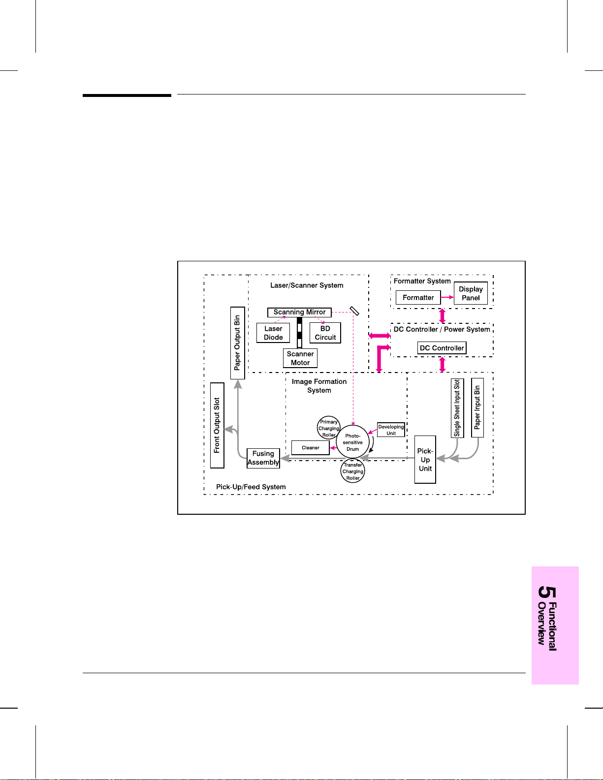
Figure 5-1
Basic Printer Functions
This chapter presents a generalized functional overview of the printer and the
printing processes. The following printer systems are discussed:
•• DC Controller System/ Power System
•• Formatter System
•• Image Formation System
•• Paper Feed System
•• Laser/Scanner System
Figure 5-1 is a generalized block diagram of the printer:
Printer Functional Block Diagram
Functional Overview 5 - 3
Page 58

Figure 5-2
DC Controller/Po wer System
The DC Controller PCA coordinates all print engine activities, drives the laser, and
coordinates print data from the Formatter PCA with the image formation process.
The DC Controller also includes both AC and dc power supply and distrib ution
circuitry. The DC Controller controls the following systems and functions:
•• Print Engine Control
•• Laser and Scanner Drive
•• Paper Motion Photosensors (Paper Out, Paper Registration, and Paper Exit
Sensors)
•• Motor
•• Power System
•• AC Power Distribution
•• DC Power Distribution
•• Overcurrent/Undervoltage Protection
•• SleepMode
•• High Voltage Power Distribution
Figure 5-2 shows the various DC controller loads.
DC Controller Loads
5 - 4 Functional Overview
AC Driver
Low-Voltage
Supply
+5V
+12V
Page 59

Print Engine Control System
Laser and Scanner Drive
Based on information received from the Formatter, the DC Controller sends signals
to the Laser/Scanner Assembly to modulate the laser diode ON and OFF and to
drive the Laser/Scanner motor. Refer to “Image Formation System,” later in this
chapter for more information.
Paper Motion Monitoring and Control
The DC Controller PCA controls paper motion by continuously monitoring the
various paper sensors and coordinating the timing with the other print processes.
For a detailed explanation of paper movement, and the interaction of photosensors
and solenoid with the paper movement process, refer to the section “Paper Feed
System,” later in this chapter.
+12 V Shutoff Switch
The 12 volt dc power shutoff switch, Switch 101, located on the top of the printer, is
activated by the printer door. The front door must be closed before the printer can
resume printing.
Engine Test Switch
The T est Print, Switch 201, located on the DC Controller, is activated manually
through an access hole at the front of the printer. This switch causes the print engine
to perform a self-test diagnostic which bypasses the Formatter PCA and prints a full
page of black vertical lines. This test is useful for troubleshooting printer problems
because it isolates the print engine from the Formatter PCA. (See Chapter 7,
“Troubleshooting,” to learn more about how to perform an engine test.)
Motor
The Motor is controlled by the DC Controller PCA. The Motor provides all of the
printer’s paper movement.
Functional Overview 5 - 5
Page 60

Power System (on DC Controller PCA)
The AC, dc, and high voltage power supply circuits are all contained within the DC
Controller PCA.
AC Power Distribution
The AC power circuitry supplies AC voltage whenever the power cord is connected
to the AC power source. AC voltage is distributed to the dc power supply circuitry
and to the AC driver circuitry, which controls AC voltage to the fusing assembly’s
heating element.
DC Power Distribution
The dc power distribution circuitry, located on the DC Controller PCA, distributes
+5 V dc and +12 V dc as follows:
+5 V dc: Formatter PCA
Photosensors
DC Controller Circuitry
Laser/Beam Detect Circuitry
+12 V dc: Motor
Scanner Motor
Solenoid
+12VA dc: High Voltage Power Supply
Overcurrent/Overvoltage Protection
There are two overvoltage /overcurrent devices in this printer:
•• Fuse F101 provides overcurrent protection for the fusing system circuitry. To
check or replace the fuse requires the removal of the DC Controller. Fuse 102
(found only on 110V units) provides overcurrent protection to the printer dc power
supply circuitry.
•• In addition, the +12V dc and +5V dc power circuitry contains an overcurrent
protection circuit which automatically shuts off the output voltage when an
overcurrent condition occurs due to a short or abnormal voltage on the load side.
SleepMode
Instead of a power switch, the printer has a SleepMode function. After the printer
has been idle for 15 minutes, it turns itself off by shifting to SleepMode. The front
panel lights remain off, and the printer retains all printer settings and downloaded
fonts and macros while in SleepMode.
The printer exits SleepMode and all of the lights power on when any of the
following occur:
5 - 6 Functional Overview
Page 61

•• A job is received.
•• The Front Panel Button is pressed.
•• The printer front door is opened.
Note
The printer will not enter SleepMode if there is a printer error.
High Voltage Power Distribution
The High Voltage Power Supply PCA applies an overlap of dc and A C voltage to
the primary charging roller and the developing roller. This circuit also applies a
positive or negati ve dc voltage to the transfer charging roller according to the
instructions from the CPU on the DC Controller PCA.
This circuit also controls the image density by changing the primary AC voltage and
the developing AC bias according to the setting of the print density dial.
High voltage is disabled when the printer’s EP Door is open (i.e., switch SW101 is
open).
Functional Overview 5 - 7
Page 62

Formatter System
The Formatter PCA is responsible for the following:
•• Receiving and processing print data from the printer interface.
•• Monitoring Front Panel Button and relaying printer status information.
•• Developing and coordinating data placement and timing with the print engine.
•• Storing font information.
•• Communicating with the host computer through the Bi-Directional Interface.
The Formatter PCA receives print data from the Bi-Tronics Interface and converts it
into a dot image. The DC Controller synchronizes the Image Formation System
with the Paper Feed System and signals the Formatter to send the print image data.
The Formatter sends the print image data (dots) in the form of a VIDEO signal and
the printing process begins.
The Formatter PCA also provides mounting locations for additional memory.
CPU
The Formatter PCA incorporates a Motorola 68030 custom-built microprocessor
operating at 24 MHz.
Read Only Memory (ROM)
Besides storing microprocessor control programs, the ROM stores dot patterns of
internal character sets (fonts).
Random Access Memory (RAM)
The RAM stores printing and downloaded font information received from the host
system and temporarily stores a full page of print image data before the data is sent
to the print engine. (See “Page Protect” later in this chapter .) Memory capacity can
be increased by adding a DRAM memory card to the Formatter PCA. Note that
adding memory may also increase print speed when printing complex graphics.
Parallel Interface
The Formatter PCA receives incoming data through its Bi-Tronics interface. The
Bi-Tronics I/O provides high speed and two-way communication between the
printer and the host, allowing the user to change printer settings and monitor printer
status from the host computer.
5 - 8 Functional Overview
Page 63

Control Panel
Status LED Lights
The Formatter uses three LEDs mounted under the printer cover to communicate
printer status to the user. Refer to “Using the Control P anel” in Chapter 3 and
“Printer Error Troubleshooting” in Chapter 7 for more information on the lights.
Front Panel Button
The Formatter PCA is connected to a microswitch located on the control panel
PCA. The single button is used for such functions as self test, reset, and to display
error codes. Refer to “Using the Control Panel” in Chapter 3 for more information
on the Front Panel Button.
Resolution Enhancement (REt)
The Formatter PCA contains circuitry for Resolution Enhancement technology
(REt), which modifies the standard video dot data on its way to the DC Controller
to produce “smoothed” black-to-white boundaries. REt is user-adjustable from
some software applications. Available settings are On or Off.
Functional Overview 5 - 9
Page 64

Figure 5-3
EconoMode
The EconoMode setting uses approximately 50% less toner than standard mode
printing by reducing the dot density. However, EconoMode does not extend toner
cartridge component life. EconoMode, which can also be thought of as “draft
mode,” is user-selectable through some software applications. The default setting is
Off.
EconoMode vs Normal Mode
Note
EconoMode does not affect print speed or memory usage.
Memory Enhancement technology (MEt)
The Hewlett-Packard Memory Enhancement technology (Met) effectively doubles
the standard memory through a variety of font and data compression methods. MEt
is only available in PCL mode and is not customer selectable. When using the
host-based driver, your PC handles memory management.
5 - 10 Functional Overview
Page 65

Enhanced I/O
The Enhanced I/O feature allows printer memory to be used for storing data
received from the host computer. When Enhanced I/O is enabled, you can send
more data to your printer in shorter amounts of time, which allows you to return to
your application sooner. Enhanced I/O has the following options:
•• Auto—allows the printer to use Enhanced I/O memory allocation to increase the
speed of data transfer from the host computer to the printer, if necessary.
•• Off—uses the minimum amount of printer memory for storing data sent from the
host computer.
Enhanced I/O is only available in PCL mode. When using the host-based driver,
your PC handles memory management.
Page Protect
Page complexity (rules, complex graphics, or dense text) may exceed the printer’s
ability to create the page image fast enough to keep pace with the Image Formation
process. If Page Protect is disabled and a page is too complex, the page may print in
parts (for example, the top half on one page and the bottom half on the next page).
Some print data loss is likely in these instances, and the printer will display an error
message.
Page Protect allows the Formatter to create the entire page image in page buffer
memory before physically moving the paper through the printer. This process
ensures that the entire page will be printed. Page Protect applies only to PCL
printing. The default setting is Auto.
PJL Overview
Printer Job Language (PJL) is an integral part of configuration, in addition to the
standard Printer Command Language (PCL). With standard Centronics cabling, PJL
allows the printer to perform functions such as:
•• Two-way communication with the host computer through a Bi-directional Parallel
connection. The printer can tell the host such things as the control panel status.
•• Isolation of print environment settings from one print job to the next. For
example, if a print job is sent to the printer in landscape mode, the subsequent print
jobs print in landscape only if they are formatted for landscape printing.
Functional Overview 5 - 11
Page 66

Figure 5-4
Image Formation System
Laser printing requires the interaction of several different technologies (such as
electronics, optics, and electrophotographics) to provide a printed page. Each
process functions independently and must be coordinated with the other printer
processes. Image formation consists of six processes:
•• Step 1. Drum Cleaning
•• Step 2. Drum Conditioning
•• Step 3. Image Writing
•• Step 4. Image Developing
•• Step 5. Image Transferring
•• Step 6. Image Fusing
Electrostatic Latent Image Formation Block
2. Scanning Exposure
1. Primary Charging
Drum Cleaning
Block
Paper Delivery
7. Drum Cleaning
Fuser Block
5. Separation
6. Fusing
Image Formation Block Diagram
4. Transfer
Transfer Block
3. Developing
Registration
Flow Of Paper
Direction Of Drum Rotation
Developing
Block
Multi-Purpose Tray
Manual Feeding Slot
5 - 12 Functional Overview
Page 67

Toner Cartridge
As the “heart” of the Image Formation System, the toner cartridge houses the
cleaning, conditioning, and developing steps of the process. The toner cartridge
contains the photosensitive drum, primary charging roller, developing station, toner
cavity, and cleaning station. Including these components, which wear, degrade, or
are consumed in the replaceable toner cartridge, eliminates the need for a service
call when replacement is required. The special photosensitive properties of the drum
allow an image to be formed on the drum surface and then transferred to paper.
CAUTION
The printer’s toner cartridge does not include a light-blocking shutter. Be careful to
avoid exposing the drum to light, which can permanently damage the drum. Protect
the cartridge whenever removing it from the printer.
Step 1: Drum Cleaning
The cleaning blade is in contact with the surface of the drum at all times. As the
drum rotates during printing, excess toner wiped off and stored in the waste toner
receptacle.
Step 2: Drum Conditioning
After the drum is physically cleaned, it must be conditioned. This process consists
of applying a uniform negative char ge on the surf ace of the drum with the primary
charging roller, located in the toner cartridge. The primary charging roller is coated
with conductive rubber. An AC bias is applied to the roller to erase any residual
charges from any previous image. In addition, a ne gative dc bias is applied by the
charging roller to create a uniform negative potential on the drum surface. The
amount of dc voltage is modified by the print density setting.
Step 3: Image Writing
During the writing process, a modulated laser diode projects the beam onto a
rotating scanning mirror. As the mirror rotates, the beam reflects off the mirror, first
through a set of focusing lenses, off a mirror, and finally through a slot in the top of
the toner cartridge, and onto the photosensitive drum. The beam sweeps the drum
from left to right, discharging the negative potential wherever the beam strikes the
surface. This creates a latent electrostatic image, which later is developed into a
visible image.
Because the beam is sweeping the entire length of the drum and the drum is
rotating, the entire surface area of the drum can be covered. At the end of each
sweep, the beam strikes the beam detect lens, generating the Beam Detect Signal
(BD). The BD signal is sent to the DC Controller, where it is converted to an
electrical signal used to synchronize the output of the next scan line of data.
Functional Overview 5 - 13
Page 68

Step 4: Image Developing
At this stage of the process, the latent electrostatic image is present on the drum.
The toner particles obtain a negative surface charge by rubbing against the
developing cylinder which is connected to a negative dc supply. The negatively
charged toner is attracted to the discharged (exposed, grounded) areas of the drum,
and repelled from the negatively charged (non-exposed) areas.
Step 5: Image Transferring
During the transferring process, the toner image on the drum surface is transferred
to the paper. A positive charge applied to the back of the paper by the transfer roller
causes the negatively charged toner on the drum surf ace to be attracted to the paper.
After separation, the drum is cleaned and conditioned for the next image.
Step 6: Image Fusing
During the fusing process, the toner is fused into the paper by heat and pressure to
produce a permanent image. The paper passes between a heated fusing element and
a soft pressure roller. This melts the toner and presses it into the paper.
5 - 14 Functional Overview
Page 69

Paper Feed System
Both the Paper Input Bin and the Single Sheet Input Slot merge into one, main input
area. Paper placed in either of these areas enables the Paper Out Sensor (sensor
202), which informs the DC Controller that paper is present.
When the printer receives a print job and is ready to print, the DC Controller
enables the Laser/Scanner Assembly and the Motor. Paper motion begins when the
DC Controller energizes solenoid SL1. This causes the paper pick up roller to rotate
once. Two actions occur as a result of this rotation. First, the paper kick plate pushes
the paper against the pick-up roller. Second, the pick-up roller grabs the top sheet
and advances it to the Feed Assembly drive rollers. To ensure that only one sheet is
fed, a main separation pad, along with two subpads, hold the remainder of the stack
in place.
The feed assembly drive rollers advance the paper to the Paper Registration
photosensor (PS203). This sensor informs the DC Controller of the exact location of
the paper’s leading edge, so that the image being written on the photosensitive drum
can be precisely positioned on the page. The feed assembly drive rollers then
advance the paper to the transfer area where the toner image on the photosensitive
drum is transferred to paper.
After the image is transferred, the paper enters the fusing assembly where heat from
the fuser and pressure from the Pressure Roller permanently bond the toner image
to paper. The P aper Exit Sensor (PS201) determines that paper has successfully
moved out of the fusing area. The fusing assembly exit rollers deliver paper to
either the Output Paper Bin or the Front Output slot, depending upon the position of
the Face-up/Face-down lever.
Functional Overview 5 - 15
Page 70

Figure 5-5
Figure 5-5 shows a simplified paper path and the locations of the photosensors and
rollers.
Simplified Paper Path
5 - 16 Functional Overview
Page 71

Figure 5-6
Figure 5-6 shows the locations of the photosensors, switches, solenoid, and other
important printer elements. Table 5-1 describes the function of each photosensor
and the solenoid.
Solenoid and Sensors
Table 5-1 Solenoid and Photosensors
No. Name Description
SL1 Paper Pick-up Solenoid Enables the Paper Pickup Roller.
PS201 Paper Exit Sensor Senses when paper has successfully moved out of the
PS202 Paper Out Sensor Senses no paper in either the Paper Input Bin or Manual
PS203 Paper Registration Sensor Detects the leading and trailing edges of the paper.
PS204 Door Open/Cartridge Sensor Detects whether printer door is open and cartridge is in
fusing area and the next sheet of paper can be fed.
Input Slot. If this sensor does not sense paper in the Input
Paper Bin or the Single-Sheet Input Slot, the formatter
displays the paper-out indication on the front panel. Paper
must be reloaded before printing can resume.
Synchronizes the photosensitive drum and the top of the
paper.
place. If the door is open or the cartridge is not in place, the
control panel LEDs will display an error message. Printing
cannot continue until the door is closed and the cartridge is
in proper position.
Functional Overview 5 - 17
Page 72

Paper Jam Detection
The Paper Out Sensor (PS202), Paper Registration Sensor (PS203), and the Paper
Exit Sensor (PS201) detect when paper is moving through the printer . (See Figure
5-5 for roller and sensor locations.) If a paper jam is detected, the DC Controller
immediately stops the printing process and causes a paper jam indication on the
front panel.
A paper jam can be detected under any of the following conditions:
•• Power-On Jams. Paper is present under either PS201 or PS203 at power-on.
•• Pickup Jams. Paper does not reach and clear photosensor PS203 within a specified
period of time. The time period begins when the Paper Pickup Solenoid (SL1) is
energized.
•• Delay Jams. Paper does not reach or clear a specific photosensor within a specified
period of time.
5 - 18 Functional Overview
Page 73

Basic Sequence of Operation
The Formatter PCA and the DC Controller PCA share information during printer
operation. The DC Controller-to-Formatter Connector (J201) forms a link which
operates as a serial data bus. This allows printer status, command information, and
dot-image data to be passed between the two PCAs. Figure 5-7 shows the general
timing of the printer events. The following events take place during normal printer
operation:
Table 5-2
Period Timing Purpose
WAIT From when the paper is inserted to the end of Main
STBY (standby) From the end of the WAIT or the LSTR period until
INTR (initial
rotation)
PRNT From the end of initial rotation until the Scanner
LSTR (last
rotation)
Motor initial rotation.
the input of the PRNT signal from the Formatter. Or
from the end of the LSTR period until power OFF.
From the input of the PRNT signal from the
Formatter until the laser diode intensity has been
stabilized.
Motor stops.
From the primary voltage (dc) OFF until the Main
Motor stops.
If another PRNT signal is sent from the Formatter,
the printer returns to the INTR period. If not, it
returns to the STBY period.
Printer Timing
Clear the drum surface potential and clean the
Transfer Roller.
Maintain the printer in ready state.
Stabilize the photosensitive drum sensitivity in
preparation for printing. Also clean the Transfer
Roller.
Form images on the photosensitive drum based on
the /VDO signal from the Formatter and transfer the
image to paper.
Deliver the last sheet of paper. Also clean the
Transfer Roller.
Refer to Timing Diagram on the next page
Functional Overview 5 - 19
Page 74

Figure 5-7
General Timing Diagram
5 - 20 Functional Overview
Page 75

Removal and Replacement
Contents
Removal and Replacement Strategy . . . . . . . . . . . . . . . . . . . . . . 6-3
Required Tools . . . . . . . . . . . . . . . . . . . . . . . . . . . . . . . . . 6-4
Installing Memory Cards (DRAM) . . . . . . . . . . . . . . . . . . . . . . 6-5
Covers and Doors . . . . . . . . . . . . . . . . . . . . . . . . . . . . . . . . 6-6
Back Cover . . . . . . . . . . . . . . . . . . . . . . . . . . . . . . . . . 6-6
EP Door Assembly . . . . . . . . . . . . . . . . . . . . . . . . . . . . . 6-8
Memory Door . . . . . . . . . . . . . . . . . . . . . . . . . . . . . . . . 6-9
Main Cover and P aper Input Assembly . . . . . . . . . . . . . . . . . . . 6-10
Internal Assemblies . . . . . . . . . . . . . . . . . . . . . . . . . . . . . . . 6-11
Control Panel . . . . . . . . . . . . . . . . . . . . . . . . . . . . . . . . 6-11
Exit Roller Assembly . . . . . . . . . . . . . . . . . . . . . . . . . . . . 6-12
Delivery Assembly . . . . . . . . . . . . . . . . . . . . . . . . . . . . . 6-13
Fuser Pressure Plate . . . . . . . . . . . . . . . . . . . . . . . . . . . . . 6-15
Heating Element . . . . . . . . . . . . . . . . . . . . . . . . . . . . . . . 6-17
Pressure Roller . . . . . . . . . . . . . . . . . . . . . . . . . . . . . . . 6-20
Face-Up/Face-Down Lever . . . . . . . . . . . . . . . . . . . . . . . . . 6-21
Fuser Exit Roller Assembly . . . . . . . . . . . . . . . . . . . . . . . . . 6-22
Paper Exit Sensor Flag . . . . . . . . . . . . . . . . . . . . . . . . . . . 6-23
Top Assemblies . . . . . . . . . . . . . . . . . . . . . . . . . . . . . . . . . 6-24
Laser/Scanner Assembly . . . . . . . . . . . . . . . . . . . . . . . . . . 6-24
Solenoid . . . . . . . . . . . . . . . . . . . . . . . . . . . . . . . . . . . 6-25
Pickup Roller Assembly . . . . . . . . . . . . . . . . . . . . . . . . . . . 6-27
Paper Feed Frame . . . . . . . . . . . . . . . . . . . . . . . . . . . . . . 6-30
Transfer Roller Guide & Transfer Roller . . . . . . . . . . . . . . . . . . 6-33
Kick Plate . . . . . . . . . . . . . . . . . . . . . . . . . . . . . . . . . . 6-34
Separation Pad . . . . . . . . . . . . . . . . . . . . . . . . . . . . . . . . 6-36
Subpads . . . . . . . . . . . . . . . . . . . . . . . . . . . . . . . . . . . 6-37
Feed Assembly . . . . . . . . . . . . . . . . . . . . . . . . . . . . . . . 6-38
Bottom Assemblies . . . . . . . . . . . . . . . . . . . . . . . . . . . . . . . 6-41
Memory Door Guide . . . . . . . . . . . . . . . . . . . . . . . . . . . . 6-41
Motor . . . . . . . . . . . . . . . . . . . . . . . . . . . . . . . . . . . . 6-42
DC Controller . . . . . . . . . . . . . . . . . . . . . . . . . . . . . . . . 6-43
Formatter Board . . . . . . . . . . . . . . . . . . . . . . . . . . . . . . . 6-46
6
Removal and Replacement 6 - 1
Page 76

6 - 2 Removal and Replacement
Page 77

Removal and Replacement Strategy
This chapter documents removal and replacement of Field Replaceable Units
(FRUs) only. Exchange assemblies should be sent to SMO for repair.
Replacement is generally the reverse of remov al. Occasionally, notes are included to
provide direction for difficult or critical replacement procedures.
WARNING!
Caution
Note
Unplug the power cord from the power outlet before attempting to service the
printer. If this w arning is not followed, severe injury may result.
Never operate or service the printer with the protective cover removed from the
Laser/Scanner Assembly. The reflected beam, although invisible, can damage your
eyes.
The sheet metal edges of this printer can be sharp! Exercise caution when working
with the printer.
The printer contains parts that are electrostatic discharge (ESD) sensitive. Alw ays
service printers at an ESD-protected workstation.
To install a self-tapping screw, first turn it counter-clockwise to align it with the
existing thread pattern, then carefully turn clockwise to tighten. Do not overtighten.
If a self-tapping screw-hole becomes stripped, repair the screw-hole or replace the
affected assembly.
Always remove the toner cartridge before removing or replacing parts.
Removal and Replacement 6 - 3
Page 78
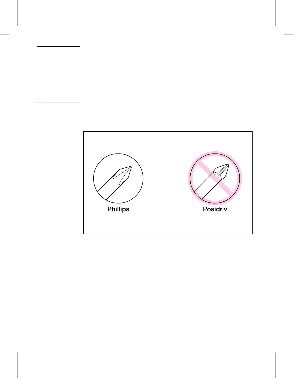
Required Tools
•• #2 Phillips Screwdriver
•• 5.5 mm Hexhead Screwdriver
•• Small Flathead Screwdriver
•• Needlenose Pliers.
Caution
Figure 6-1
A Posidriv screwdriver will damage the printer’s screw heads. Use Phillips only.
Figure 6-1 shows the difference between a Phillips and a Posidri v screwdriver. Note
that a Phillips tip has more beveled surfaces.
Phillips and Posidriv screwdrivers
6 - 4 Removal and Replacement
Page 79

Installing Memory Cards (DRAM)
1 Unplug the power cord from the printer. You
should not install a memory card while the
printer is in SleepMode.
2 Open the Printer Door, remove the toner
cartridge, and close the Printer Door. Protect
the toner cartridge from light while you are
working on the printer.
3 Remove any paper in the paper tray. Gently
tip the printer onto its side so that the memory
cover is on top as shown in Figure 3.
4 Remove the Memory Expansion Cover by
carefully pulling the tab out and away from
the printer in a gentle rocking motion.
5 Align the memory card with the corner notch
so it is positioned as in Figure 4. Push it firmly
into the printer.
Replace the Memory Expansion Cover, set the
printer upright, reinstall the toner cartridge,
reinsert paper, and reconnect to the power source.
Print a self-test page (see Chapter 3) to check that
the printer recognizes the additional memory you
have added. Your Total Memory in the “Printer
Information” section will show the new MB total.
1 MByte card 2 MByte total
2 MByte card 3 MByte total
4 MByte card 5 MByte total
8 MByte card 9 MByte total
Removal and Replacement 6 - 5
Page 80

Covers and Doors
Back Cover
1 Unplug the power cord and remove the parallel cable from the back of the printer.
2 Remove the toner cartridge.
3 Lift the Input Extender assembly.
Caution
Figure 6-2
You must lift the Input Extender when the covers are removed or it will break.
4 Remove the (3) screws (Figure 6-2, callout 1).
Back Cover Removal (1 of 2)
6 - 6 Removal and Replacement
Page 81

Figure 6-3
5 Separate the rear panel from the main cover, pulling the lower corners away from
the printer first, then using a flathead screwdriver to pry the two upper corners apart
(Figure 6-3, callout 1).
6 To remove the cover, pull it downward (Figure 6-3, callout 2).
Back Cover Removal (2 of 2)
To reinstall
Make certain the Input Extender is up.
Removal and Replacement 6 - 7
Page 82

Figure 6-4
EP Door Assembly
1 Unplug the power cord and remove the parallel cable from the back of the printer.
2 Open the EP door.
3 Remove the toner cartridge.
4 Along the door hinge, there is a flex point. Press the left tab inward to release it.
The right tab will fall out easily (Figure 6-4).
EP Door Assembly Removal
6 - 8 Removal and Replacement
Page 83

Figure 6-5
Memory Door
1 Unplug the power cord and remove the parallel cable from the back of the printer.
2 Remove the toner cartridge.
3 Gently tip the printer onto its side so that the Control Panel is on top.
4 Carefully pull the door tab out (Figure 6-5, callout 1) and away from the printer in a
gentle rocking motion (Figure 6-5, callout 2).
Memory Door Removal
Removal and Replacement 6 - 9
Page 84

Main Cover and Paper Input Assembly
1 Remove the toner cartridge.
2 Remove memory door.
Caution
Figure 6-6
Remove the memory door first. The door will break if you remov e the Main Cover
without removing the memory door.
3 Remove the EP Door Assembly.
4 Remove the Back Cover.
5 Remove the (2) screws from the top of the printer (Figure 6-6, callout 1).
6 Grasp the two lower, front corners of the printer and pull gently outward to release
the front of the Main Cover.
7 Lift the cover straight off.
8 Remove the Paper Input Assembly (Figure 6-6, callout 2) by rotating it forward and
lifting it out.
Main Cover and Paper Input Assembly Removal
Note
When replacing the Paper Input Assembly, mak e certain that the mylar sheet is
positioned between the Input Feed Roller and Separation Pad.
6 - 10 Removal and Replacement
Page 85

Figure 6-7
Internal Assemblies
Control Panel
1 Remove the Printer Covers.
2 Release the Control Panel connector (Figure 6-7, callout 1).
3 Press the tab on the top of the Control Panel downward (Figure 6-7, callout 2). The
Control Panel will pop out of the printer chassis.
4 Lift the Control Panel out.
Control Panel Removal
Removal and Replacement 6 - 11
Page 86

Figure 6-8
Exit Roller Assembly
1 Remove Printer Covers.
2 Grasp the tabs at the lower ends of the Exit Roller bushings and pull inward. This
will release the tabs from the printer chassis (Figure 6-8, callout 1).
3 Rotate the tabs 90 degrees, clear of the printer chassis (Figure 6-8, callout 2).
4 Lift the roller out.
Exit Roller Removal
6 - 12 Removal and Replacement
Page 87

Delivery Assembly
1 Remove the Printer Covers and Exit Roller Assembly.
2 Remove the EP Right-Hand assembly by pressing the tab in (Figure 6-9, callout 1)
and sliding the assembly toward the front of the printer (Figure 6-9, callout 2).
Note
Figure 6-9
The EP Right-Hand assembly must be removed to access any fuser components.
Delivery Assembly Removal (1 of 2)
Removal and Replacement 6 - 13
Page 88

Figure 6-10
3 Remove the (2) screws (Figure 6-10, callout 1). Once the screws have been
removed, rotate the rear of the assembly up and lift it out of the printer.
Delivery Assembly Removal (2 of 2)
Caution
Upon replacement, make certain that the positioning pins on the bottom of the
assembly are properly positioned before tightening the screws.
Note
The tabs on the front end of the Delivery Assembly must fit under the sheet metal
fuser plate below.
6 - 14 Removal and Replacement
Page 89

Figure 6-11
Fuser Pressure Plate
1 Remove Printer Covers and Delivery Assembly (Figures 6-9 and 6-10).
2 Remove the (2) screws (Figure 6-11, callout 1).
3 Press the Fuser Plate retainer clips out to release the Pressure Plate (Figure 6-11,
callout 2).
4 Rotate the plate around and lift up to remove it (Figure 6-11, callout 3).
Fuser Pressure Plate Removal
Removal and Replacement 6 - 15
Page 90

Figure 6-12
To reinstall:
The Fuser Pressure Plate is kept in place by four locking mechanisms in each
corner. Place the rear slits in the plate o ver the rear brackets that hold the Fusing
Assembly (Figure 6-12, callout 1). Lower the plate over the retaining clips, pressing
on both sides of the Fuser Pressure Plate (Figure 6-12, callout, 2). It is important
that the spring is placed over the positioning pin (callout 3) or the toner cartridge
will not glide into place. Replace the screws.
Fuser Pressure Plate Replacement
6 - 16 Removal and Replacement
Page 91

Figure 6-13
Heating Element
1 Remove Printer Covers, Delivery Assembly (Figures 6-9 and 6-10), and Fuser
Pressure Plate (Figure 6-11).
2 Remove the wire cover (on the right side of the printer) for the Heating Element
wires by pressing in on the tab and pulling outward (Figure 6-13, callout 1).
Heating Element Removal (1 of 3)
Removal and Replacement 6 - 17
Page 92

Figure 6-14
3 Disconnect the AC voltage to the Heating Element by releasing the connector
located on the DC Controller. Press down on the connector release with a small,
flathead screwdrive r (Figure 6-14, callout 1). (Since this is a small space, it is much
easier to reach the connector with a screwdrive r.) Pull straight out (Figure 6-14,
callout 2).
Heating Element Removal (2 of 3)
6 - 18 Removal and Replacement
Page 93

Figure 6-15
4 Remove the wire from the wire guides along the right-side of the printer.
5 Disconnect the thermistor feedback connector in the left front side of the Fusing
Assembly (Figure 6-15).
Heating Element Removal (3 of 3)
6 Lift the Heating Element out.
Removal and Replacement 6 - 19
Page 94

Figure 6-16
Pressure Roller
1 Remove Printer Covers, Delivery Assembly (Figures 6-9 and 6-10), Fuser Pressure
Plate (Figure 6-11), and Heating Element (Figures 6-13 through 6-15).
2 Remove the Pressure Roller guide by lifting the edge (Figure 6-16, callout 1) and
then rolling it gently backward (Figure 6-16, callout 2).
Pressure Roller Removal
3 Lift the right end of the Pressure Roller up and out of the printer chassis. The left
side will follow easily with the Pressure Roller gear still attached.
Note
When reinstalling the Pressure Roller, apply a drop of grease to the grounding plate
on the right side of the shaft. (Refer to Chapter 8 for a part number.)
6 - 20 Removal and Replacement
Page 95

Figure 6-17
Face-Up/Face-Down Lever
1 Remove Printer Covers, Delivery Assembly (Figures 6-9 and 6-10), Fuser Pressure
Plate (Figure 6-11), and Heating Element (Figures 6-13 through 6-15), and Pressure
Roller (Figure 6-16).
2 Rotate the lever forward 90 degrees (past the spring) and pull it straight out the front
of the printer.
To reinstall
1 Make sure the lever arm is on the left and is initially pointing downward.
2 Pull the spring forward using needlenose pliers.
3 Slide the short, round tabs into the grooves on the Separation Guide Assembly. The
machined ridges on the lever will face you.
4 Release the spring so it falls in place in front of the square tab (Figure 6-17).
Note
Face-Up/Face-Down Lever Replacement
You can tell when the lever is in place because there are two plastic grooves that fit
precisely in front of the Exit Rollers, and you should be able to feel the spring’s
release mechanism.
Removal and Replacement 6 - 21
Page 96

Figure 6-18
Fuser Exit Roller Assembly
1 Remove Printer Covers, Delivery Assembly (Figures 6-9 and 6-10), Fuser Pressure
Plate (Figure 6-11), and Heating Element (Figures 6-13 through 6-15), Pressure
Roller (Figure 6-16), and Face-Up/Face-Down Le ver (Figure 6-17).
2 Remove the gear from the left end of the roller shaft.
3 Remove the Exit Roller Assembly by pressing the small, white tab upward (Figure
6-18, callout 1) and rotating it around (Figure 6-18, callout 2).
4 Slide the Exit Roller Assembly forward and out to the right of the printer .
Fuser Exit Roller Removal
6 - 22 Removal and Replacement
Page 97

Paper Exit Sensor Flag
1 Remove the Printer Covers, Delivery Assembly (Figures 6-9 and 6-10), and Fuser
Pressure Plate (Figure 6-11).
2 Remove the Paper Exit Sensor flag by pressing down on the left side and pulling up
on the right side.
To reinstall
Note
Figure 6-19
It is important that you reinstall the flag correctly, since installing it incorrectly will
cause the Control Panel to display an error with the Paper Exit Sensor (PS201).
Place the left side of the flag in the correct position first, then slide the right side
into place, making certain the spring is on top of the flag (Figure 6-19). The flag
should fit snugly in place.
Paper Exit Sensor Flag Replacement
Removal and Replacement 6 - 23
Page 98

Figure 6-20
T op Assemblies
Laser/Scanner Assembly
1 Remove the Printer Covers.
2 Remove both Laser/Scanner connectors (Figure 6-20, callout 1).
3 Remove all (4) screws and lift the assembly straight off (Figure 6-20, callout 2).
Laser/Scanner Assembly Removal
6 - 24 Removal and Replacement
Page 99

Figure 6-21
Solenoid
1 Remove the Printer Covers.
2 On the left side of the printer, remove the paper pickup gear (Figure 6-21, callout 1)
by pressing the tabs in the center of the gear outward and pulling the gear off
(Figure 6-21).
Solenoid Removal (1 of 2)
Removal and Replacement 6 - 25
Page 100

Figure 6-22
3 Remove the Solenoid connector (J204) from the DC Controller (Figure 6-22,
callout 1).
4 Remove the self-tapping screw that holds the Solenoid in place (Figure 6-22, callout
2).
5 Unthread the wires from the printer chassis.
6 Lift the Solenoid off.
Solenoid Removal (2 of 2)
Note
When reinstalling this part, the Paper Pickup Gear is keyed to go on the shaft in
only one way.
6 - 26 Removal and Replacement
 Loading...