

Page 1

HP Cluster Platform
c–Class Blade Cable Management Bracket
Installation Guide
*5991-6764*
Printed in the US
HP Part Number: 5991-6764
Published: October 2006
Page 2

© Copyright 2006 Hewlett-Packard Development Company, L.P.
The information contained herein is subject to change without notice. The only warranties for HP products and services are set forth in the express
warranty statements accompanying such products and services. Nothing herein should be construed as constituting an additional warranty. HP
shall not be liable for technical or editorial errors or omissions contained herein.
Printed in the U.S.A.
Page 3
1 Preparing for Installation
Audience
This guide is intended for HP service representatives and other persons trained to install hardware options
in HP 10000–series racks. Such persons are expected to understand the hazards of working in this
environment and to take suitable precautions to minimize danger to themselves and others.
Documentation Resources
You can download the documentation for components referenced in this installation guide from the
following locations:
• HP 10000 Series Rack (Documentation option):
http://h18004.www1.hp.com/products/servers/proliantstorage/racks
• HP Technical Documentation, (High Performance Computing option):
http://docs.hp.com/en/highperfcomp.html
Kit Description
The c-Class Blade cable management bracket aligns and supports cables that lead from a 4x DDR IB
(InfiniBand) Switch Module mounted in the rear of the c-Class server blade enclosure to another switch
module, or to a similar interconnect device. The kit provides strain relief for the cables connected to the
individual InfiniBand interconnect ports and ensures a good connection. It also ensures the correct bend
radius for the cable and provides channels for cable routing and cable management. One cable management
bracket is required for each InfiniBand switch module.
NOTE: The cable management bracket is designed to support 0.357 inch (9.0678 mm) diameter, 0.438
inch (11.1252 mm) diameter, and 0.309 inch (7.8486 mm) diameter InfiniBand cables. Consult the
documentation supplied with your model of HP Cluster Platform before installing the brackets and routing
the cables.
Kit Contents
Verify that kit contains the following components:
• Packaging and documentation.
• The bracket hardware shown in Figure 1-1 “Bracket Hardware”.
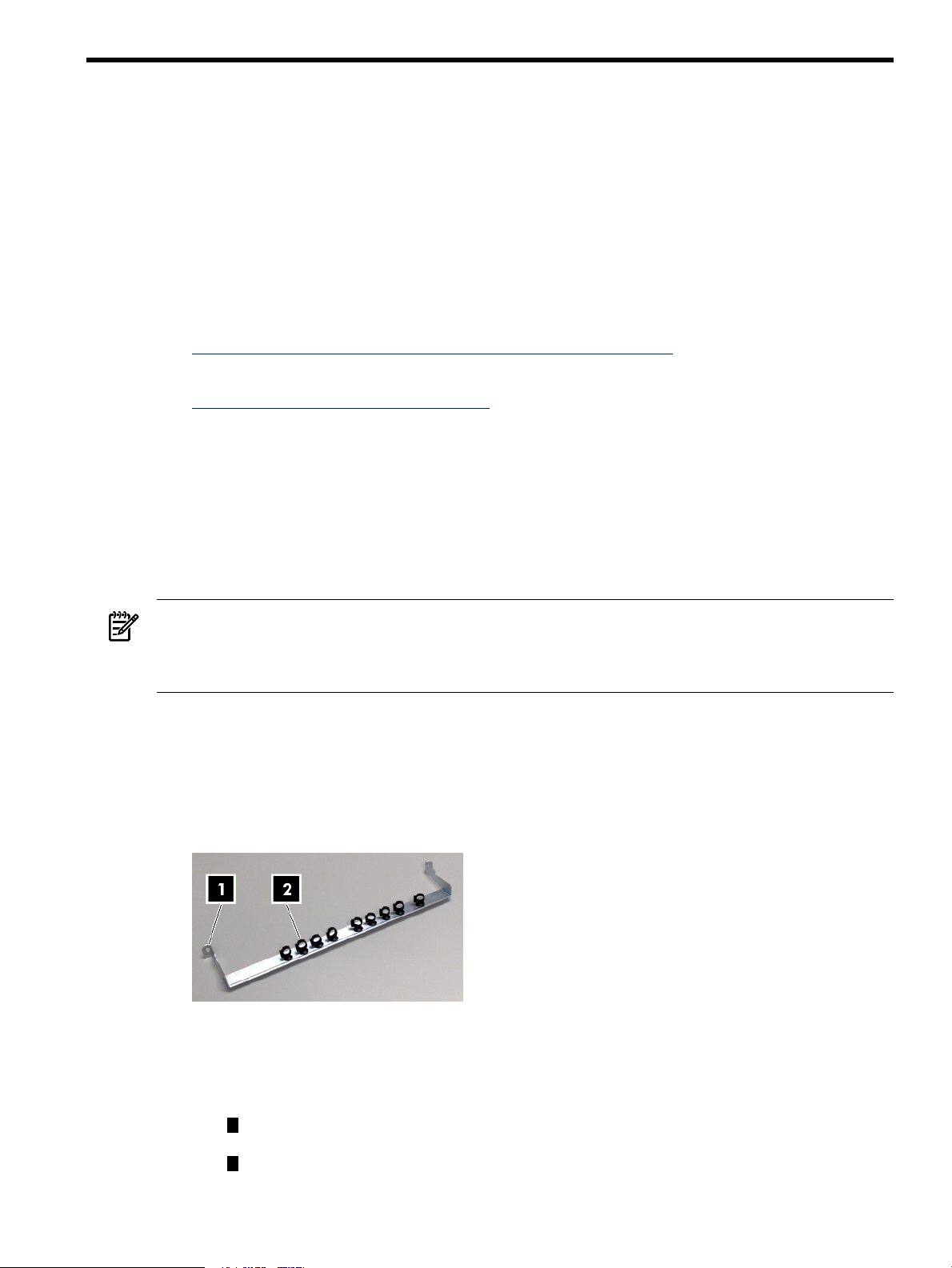
Figure 1-1 Bracket Hardware
The c-Class server blade enclosure cable management bracket is used in HP Cluster Platform
configurations, however, it might be adapted to other HP Cluster Platform cable management
applications (see the installation documentation for your hardware). The following features are called
out in the illustration above:
1
Bracket mounting hook and rack attachment hole for the rack fasteners described in
Table 1-1 “Fasteners”.
2
9 locking cable clips, preinstalled in the bracket.
Contact your HP sales representative if any parts are missing or damaged.
Audience 3
Page 4

The fasteners specified in Table 1-1 “Fasteners” are required to secure the bracket to the rack columns.
These fasteners are provided with HP 10000–series racks.
Table 1-1 Fasteners
DescriptionTorqueFormatSizeQty.
M6 screws2
To prevent screws from becoming loose because of vibration, HP recommends that you use an adjustable
torque drive, set to the torque specifications given in the table above.
Required Resources
To install the c-Class blade cable management bracket, you require the following resources:
• Tools:
— Screwdriver, #2 (medium) Phillips.
— Cage-nut insertion tool (shipped with the rack) or a flat-bladed screwdriver.
— Marker pen or masking tape.
— Short stepladder or platform that enables you to install brackets in the upper part of the rack.
• Resources: Cables of the type used by the system interconnect.
Prerequisites
Before you begin to mount the bracket:
• Follow the usual cable handling precautions for InfiniBand cables, see the HP Cluster Platform InfiniBand
Interconnect Installation and User's Guide.
• Ensure you know how to plug in the InfiniBand cables, as described in see the HP Cluster Platform
InfiniBand Interconnect Installation and User's Guide.
• Read the rack installation instructions for the c-Class blade enclosure.
• Obtain the set of cabling tables required for your HP Cluster Platform solution.
screw
N/ASquare nutM6 cage nuts2
Cage nut for M6 machine screw. A square nut that clips into the
rear face of the rack column
Rack machine screw. For use with M6 cage nut.25–30 in/lbPan-head machine
IMPORTANT: Do not secure the enclosure into the rack before you begin the bracket installation. You
must be able to access the rear (inward) face of the rack columns.
4 Preparing for Installation
Page 5

2 Aligning the Bracket
U10
U9
U8
U7
U6
1
3
2
Figure 2-1 “Bracket Orientation” shows the correct orientation of the cable management bracket which
you must install before connecting the cables to the InfiniBand switch module. During the cabling procedure,
the bracket provides strain relief for the InfiniBand ports, and maintains the correct minimum cable bend
radius.
Figure 2-1 Bracket Orientation
Callout 1 shows the bracket's mounting hook, installed in one of the square holes in the left rear rack
column. The actual mounting locations for a bracket are relevant to the location of the blades enclosure
in the rack, and must align with the switch module installed in the c-Class blade enclosure. Figure 2-2
identifies relative mount locations.
Figure 2-2 Relative Mounting Locations for a Bracket
The callouts in Figure 2-2 identify the following features:
1
The U location that aligns with the top of the blades enclosure. Each enclosure us 10U high.
2
Filled squares – One of three potential cutouts (mounting holes) where you mount the bracket's
hook.
3
Circled squares – One of three potential cutouts where you locate a fastener.
Use the following procedure to determine the actual mounting locations for brackets:
1. Determine which of the blades chassis bays contain the InfiniBand switch modules. (There might be
more than one InfiniBand switch module in some configurations).
2. Determine the rack U location that aligns with the top of the blades enclosure.
3. Using a pen or masking tape, mark the mount locations defined in Table 2-1.
5
Page 6

Table 2-1 Bracket Mount Locations
Bay 3 and 4.
blades enclosure.
Bay 5 and 6.
blades enclosure.
Bay 7 and 8.
blades enclosure.
Fastener Cut-outBracket Hook Cut-outRelative U LocationInfiniBand Switch Module Bay
Middle cutout.Top cutout.4th U down from the top of the
Bottom cutout.4th U down from the top of the
Top cutout of the next U
location below (5th).
Bottom cutout.Middle cutout.5th U down from the top of the
6 Aligning the Bracket
Page 7

3 Installing and Using the Bracket
One bracket is required for each 8–port InfiniBand switch module, typically installed in bays 3 and 4 of
the c-Class server blade enclosure in HP Cluster Platform. When installed, the bracket occupies less than
1U (1.75 inches) of rack column space.
Use the following procedure to install the c-Class server blade enclosure cable management bracket:
CAUTION: When performing the installation procedure, extend only one blade enclosure no more than
a few inches from the rack at any time. Ensure that the rack is stable before you begin the installation
procedure.
1. Starting from the lowest bracket, using the fastener locations that you identified and marked in
Chapter 2 (page 5), clip a cage nut into the back of each rear rack column.
2. Hook the bracket onto the square cutouts in the rack column.
3. Fasten bracket to the rear rack columns by using two M6 pan-head screws and tighten to the specified
torque.
4. Repeat Steps 1 through 3 if more than one bracket is required.
5. Slide the blade enclosure into the rack and secure it at the front of the rack as specified in the installation
instructions for the blade enclosure.
6. Starting at the lowest port and working up through the rack, consult the cabling tables for your HP
Cluster Platform solution and begin connecting the cables.
7. Open the cable clips by pressing in the latch as indicated by callout 1 in Figure 3-1.
Figure 3-1 Cable Clips
8. Connect the cable to the InfiniBand switch module port, ensuring that the latch on the cable head-shell
engages.
(If you are connecting live links, as recommended in the HP Cluster Platform documentation, the port
signal LEDs will illuminate and indicate the link status.)
9. Close the cable clip by pressing firmly on the location indicated by callout 2 in Figure 3-1.
10. Route the cable to its next point of support, as defined by the cable management solution for blades
clusters.
11. Repeat steps 7 through 10 until all cable connections are completed.
12. To disconnect a cable, unlatch its locking mechanism and remove it from the port by pulling on the
headshell. (You can leave the cable secured in the clip when making a temporary disconnection or
when extending the blades enclosure from the front of the rack, as shown in Figure 3-2.)
7
Page 8

Figure 3-2 Cables Installed
It is not normally necessary to dismantle or remove the bracket in order to perform any service operations
on the blades enclosure, such as replacing InfiniBand switch modules. However, if you need to remove
the bracket, use the following procedure:
1. Bring the cluster and the rack to a power-safe and stable state.
2. Disconnect all cables and secure them out of the work area, ensuring that the cables remain within
their specified bend radius while they are not supported by the bracket.
3. Remove the two M6 screws that secure the bracket to the rack.
4. Unhook and remove the bracket from the rack columns.
8 Installing and Using the Bracket
 Loading...