

Page 1

HP NetServer
Fibre Channel Host Bus
Adapter Installation Guide
HP Part Number 5971-0825
Printed in November 2000
Page 2

Notice
The information contained in this document is subject to change without notice.
Hewlett-Packard makes no warranty of any kind with regard to this
material, including, but not limited to, the implied warranties of
merchantability and fitness for a particular purpose. Hewlett-Packard shall
not be liable for errors contained herein or for incidental or consequential
damages in connection with the furnishing, performance, or use of this material.
Hewlett-Packard assumes no responsibility for the use or reliability of its
software on equipment that is not furnished by Hewlett-Packard.
This document contains proprietary information that is protected by copyright.
All rights are reserved. No part of this document may be photocopied,
reproduced,or translated to anotherlanguagewithout the prior written consentof
Hewlett-Packard Company.
Novell NetWare® is a registered trademark of Novell, Inc. SCO®, SCO
OpenServer®, and UnixWare® are registered trademarks of The Santa Cruz
Operation,Inc. Windows®2000 and Windows NT® are registered trademarks of
Microsoft Corporation, SCSISelect® is a registered trademark of Adaptec.
Intel® and Pentium® are registeredtrademarks of Intel Corporation.
Hewlett-Packard Company
Network Server Division
Technical Communications/MS 45SLE
10955 Tantau Avenue
Cupertino, CA 95014 USA
© Copyright 2000, Hewlett-Packard Company.
Audience Assumptions
This Installation and Configuration Guide is for the person who installs,
administers,andtroubleshootsL AN servers. Hewlett-PackardCompany assumes
you are qualified in the servicing of computer equipment and trained in
recognizing hazards in products with hazardous energy levels.
ii
Page 3

Contents
1 Introduction............................................................................... 1
Audience for this Manual...................................................................................... 1
What is the Hewlett-Packard Fibre Channel Adapt er? ......................................... 1
Contents of the Fibre Channel Adapter Kits......................................................... 1
What Is Needed Besides the Adapter . ................................................................. 2
Adapter Overview................................................................................................. 2
System Requirements.......................................................................................... 4
Windows NT Systems....................................................................................... 4
Windows 2000 Systems ................................................................................... 4
NetWare Systems............................................................................................. 4
2 Installation................................................................................. 5
Overview............................................................................................................... 5
Installing Adapter in PCI Slot................................................................................ 5
General Steps................................................................................................... 5
GBIC Overview..................................................................................................... 6
Installing the G BIC................................................................................................ 7
Connecting Cables............................................................................................... 8
Removing the GBIC.............................................................................................. 9
Verifying the Adapter ..........................................................................................10
3 Windows NT Driver Installation............................................. 13
Overview .............................................................................................................13
Installing the Driver .............................................................................................13
Removing the Driver ...........................................................................................14
4 Windows 2000 Driver Installation ..........................................15
Overview .............................................................................................................15
Installing the Driver .............................................................................................15
Removing the Driver ...........................................................................................16
Additional Notes ..............................................................................................16
iii
Page 4

5 NetWare Driver Loading .........................................................17
Overview .............................................................................................................17
Driver Loading on an Existing NetWare Server ..................................................17
Unloading the Driver ...........................................................................................19
Updating the Driver .............................................................................................19
6 PCI Hot Plug Support .............................................................21
7 Troubleshooting ......................................................................23
A Electrostatic Discharge (ESD) ..............................................25
PreventingElectrostatic Damage ....................................................................... 25
Grounding Methods ............................................................................................25
B Regulatory Information .........................................................27
Regulatory N otic es .............................................................................................27
Electromagnetic Compliance ..........................................................................27
Notice for United States ..................................................................................28
(FederalCommunications Commission) .........................................................28
Class A Accessories .......................................................................................29
Notice for Canada ...........................................................................................29
Notice for Japan ..............................................................................................29
Notice for Taiwan ............................................................................................30
Notice for European Union .............................................................................30
Declaration of Conformity (US, EU, China) ....................................................31
C Specifications ........................................................................33
Fibre Channel Operation ................................................................................33
D Software License Terms .......................................................35
E Fibre Channel Cables ............................................................37
F Warranty and Support ...........................................................39
Hardware Accessories Limited Warranty ...........................................................39
Hewlett-Packard Hardware Accessories ........................................................39
iv
Page 5

Third-Party Hardware Products ......................................................................40
HP Repair and Telephone Support ....................................................................40
U.S. and Canada ............................................................................................40
Other Countries ..............................................................................................40
World Wide Web .................................................................................................40
v
Page 6

vi
Page 7

1 Introduction
Audience for this Manual
This guide is intended for network administrators, maintenance engineers or
qualified personnel who m aintain and/or update servers. Since installing this
Adapter involves both hardware a nd software installation functions, it is
importantthat the person installing the adapter is familiar with performing such
tasks as installing PCI cards, connecting cables, and installing software drivers.
What is the Hewl e tt-Packard Fibre Channel
Adapter?
The Hewlett-Packard Fibre Channel Adapter is a reliable, high performance
serialI/O storage interfacefor servers. The serial nature of Fibre Channelbrings
the flexibility and ease of use of LAN connectivity to storage attachment,
introducingtheidea of Storage Area Networks (SAN). Fibre Channel simplifies
the physical configuration issues related to the I/O channel. Peripherals m ay be
positioned at considerable distances from the server (depending on cabling
media) for convenience or for data security. More reliable in data transfer than
conventional LAN, Fibre Channel offers Gigabit performance and greater
device connectivity t han parallel SCSI. The 32/64 bit, 33 M Hz, 1 Gigabit HP
Fibre Channel Adapter provides the I/O channel scalabilityrequired for
continuous growth in storage capacity and availability needs.
The Hewlett-Packard Fibre Channel Adapter is configuredto run on an
Arbitrated Loop, or a Fabric environment,Class 3 operation with the SCSI FCP
protocol. The SCSI FCP protocol allows the use of the standard Windows NT
SCSI miniport interface, thus blending the Hewlett-Packard Fibre Channel
Adapter’s revolutionary I/O t echnology with evolutionary requirements of
standards-based servers.
Contents of the Fibre Channel Adapter K its
This section describes what is in the HP Fibre Channel Adapter kit. The kit
contents are as follows:
1
Page 8

• Fibre Channel Host Bus Adapter (HBA)
• A Hewlett-Packard Navigator CD containing the available adapter
driver(s)
• A documentation CD containing the Fibre Channel Host Bus Adapter
Installation Guide
• This installation guide
What Is Needed Besides the Adap ter
Besides the Fibre Channel HBA, you will need the following:
• A GBIC module supported by the Fibre Channel HBA
• A fibre channel cable, either optical or copper
• A fibre channel device (such as the Fibre Channel Hub) to connect to the
GBIC module
Adapter Overview
The HP Fibre Channel Adapter is a PCI to Fibre Channel controller card that
provides a one Gigabit serial interface between a server and a Fibre Channel
storage system. The cabling between the storage system and the interface card
can be either fiber optic or copper.
2
Page 9
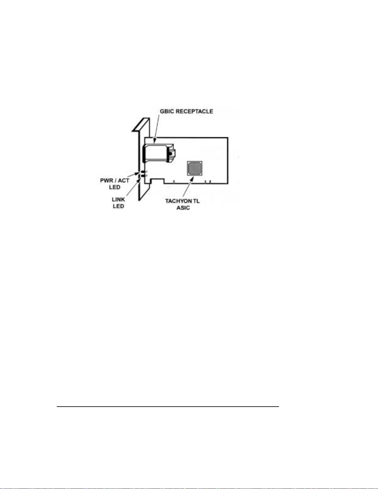
Figure 1-1. 32/64 bit PCI, 33 MHz PCI, 1 Gbit
The HP Fibre Channel Adapter installs into a standard PCI (Peripheral
Component Interconnect) slot. This adapter supports a high performance 64-bit
PCI bus (backward compatible to 32-bit) with multiplexed address and data
lines,and parity information. The PCI bus provides a high speed (up to 264/132
Megabytes/sec) path between the system board and the Fibre Channel Adapter.
The HP Fibre Channel Adapter is a PCI Bus Master device and conforms to the
PCI Local Bus Specifications version 2.1.
The D8602B Fibre Channel Adapter requires the installation of a Gigabit
Interface Converter (GBIC) module before connecting the Fibre Channel
cables.See the GBIC Overview section in Chapter 2.
3
Page 10

System Requirements
Windows NT Systems
The following items are required when you install the HP Fibre Channel
Adapter into a Windows NT system:
• A Pentium or higher system with PCI local bus
• Windows NT 4.0 installed with at least service pack 4
• Minimum recommended system memory is 32 MBytes
Windows 2000 Systems
The following items are required when you install the HP Fibre Channel
Adapter into a Windows2000 system:
• A Pentium or higher system with PCI local bus
• Windows 2000 RTM installed
• Minimum recommended system memory is 64 MBytes
NetWare Systems
The following items are required when you install the HP Fibre Channel
Adapter into a Novell NetWare system:
• A Pentium or higher system with PCI local bus
• Novell NetWare 5 installed
• Minimum system memory of 32 MBytes
4
Page 11

2 Installation
Overview
Before installing the Adapter in your server, make sure that the system is
powered down a nd that you follow ESD procedures to reduce the risk of
damage to the Adapter or the server electronics. See Appendix A regarding
ESD information.
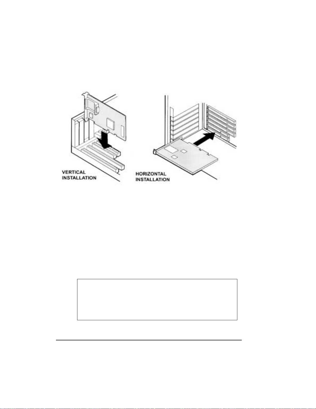
Installing Adapter in PCI Slot
Install the Adapter in any standard PCI slot. The following generalized
installation steps pertain to most PCI installations. Most system chassis are
either vertical or horizontal orientated, therefore, you should install your card
dependingon the orientation of your system.Consult your server or workstation
manual for PCI card installation.
General Steps
1. Back up your work and turn off power to your system.
2. Remove the chassis cover.
3. Locate an empty PCI expansion slot in your system.
4. Remove the expansion slot cover. (S ave the slot cover screw.)
5. Insert the HP Fibre Channel Adapter into the slot until it is firmly seated.
Refer to Figure 2-1. on page 6.
6. Replace the slot cover s crew.
5
Page 12
GBIC Overview
A GBIC converts internal electrical signals to external electrical or optical
signals for transmission across the Fibre C hannel media. The Fibre Channel
cable inserts into the connector of the GBIC module.
There are several types of GBIC modules currently availablethat can be used in
the D8602B Fibre C hannel Adapter. GBICs are “hot pluggable,” which means
they c an be plugged into, or pulled out of the Adapter while the power is
applied.
CAUTION Do not remove or insert the Ada pter while power is
Figure 2-1. Installing Adapter
applied. If you do switch GBICs while the system is
powered up, make sure the Adapter is s ecured in the PCI
slot. If the Adapter is not secured in the PCI slot, damage
may occur to the Adapter and possibly the system’slogic
board.
6
Page 13
CAUTION Inserting a passive GBIC without Fibre Channel device/
hub attached will cause an open loop condition.This open
loop condition will prevent devices attached to the internal
HSSDC connector from functioning. To avoid this
situation,avoid inserting the passive GBIC until external
Fibre Channel devices are attached to the passive G BIC.
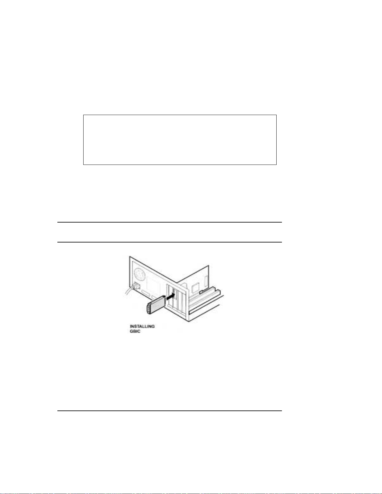
Installing the GBIC
Select the type of GBIC module that is compatible with your system.
• Installthe GBIC into the receptacle on the Adapter.
Refer to Figure 2-2 below.
NOTE You can only install the GBIC one way, as the GBIC and guide rails
inside the Adapter receptacle are keyed.
Figure 2-2. Installing GBIC Module
7
Page 14
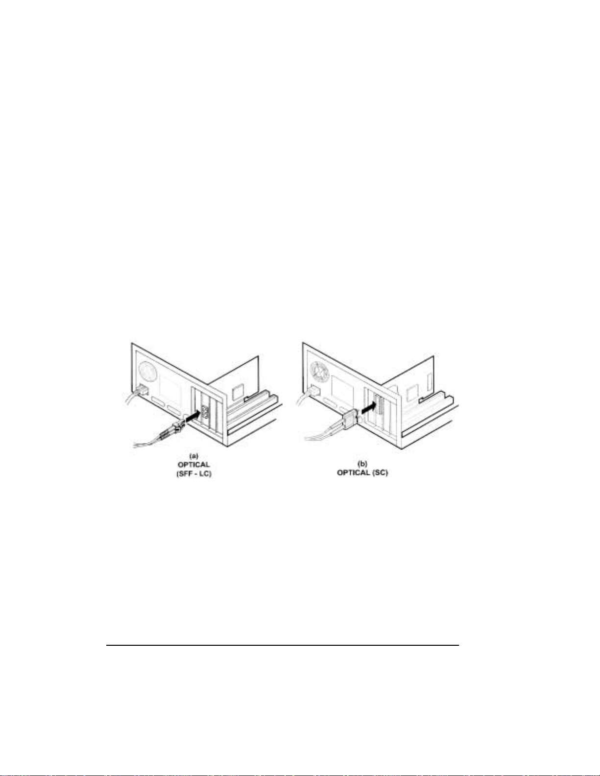
Connecting Cables
1. If you are using an optical GBIC module, remove the dust plug covers
protecting the optical connectors before inserting the fibre-channel cable. Save
the dust plug covers for future use.
2. Select the correct cable that matches the GBIC you installed and install the
end connectors into the GBIC. The GBIC and Fibre Channel cable a re keyed, so
they c an only fit one wa y. Refer to Figure 2-3. on page 8 for optical cable
connection and Figure 2-4. on page 9 for copper cable connection.
3. Support the Fibre Channel cable so that you do not have a bend radius of less
than 3 inches.
4. Support and route the Fibre Channel cable to prevent damage from sharp
edges or from being crushed by nearby equipment.
Figure 2-3. Optical (SFF - LC) and Optical (SC) Cable Connector
8
Page 15
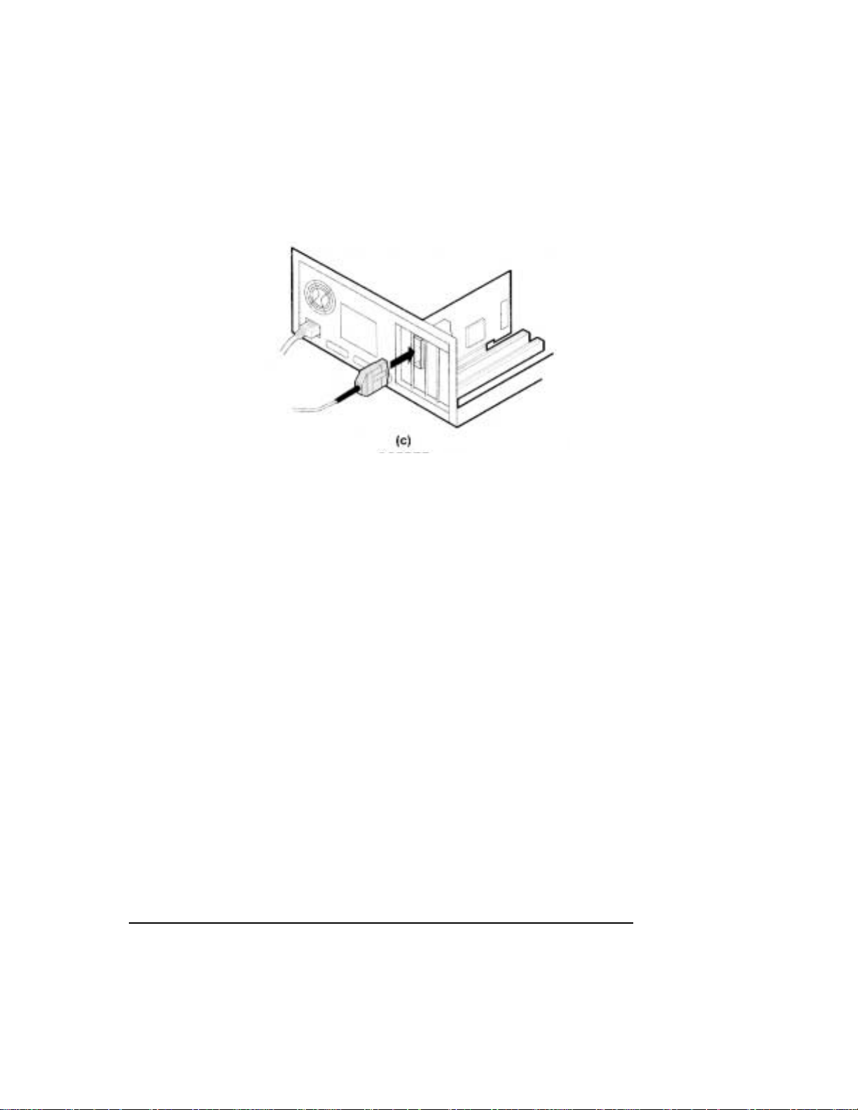
Figure 2-4. Copper Cable Connector
Removing the GBIC
To remove the GBIC, follow these steps:
1. Remove the Fibre Channel cable.
(a) If you a re using the HSSDC Copper Cable, squeeze the tab to
remove. (See Figure 2-6. on page 10.)
2. (a) If you are using an optical GBIC, flip the bar of the GBIC to the
“OPEN” position and pull to remove. (See Figure 2-5. on page 10.)
(b) If you are using the HSSDC Copper GBIC, squeeze the tabs on both
sides of the GBIC. (See F igure 2-6. on page 10.)
3. Pull the module out of the receptacle.
4. For optical GBICs, reinsert the dust plug.
9
Page 16

Figure 2-5. Removing the Optical GBIC Module
Figure 2-6. Removing t he HSSDC Copper GBIC Module
Verifying the Adapter
You can verify the Adapter and cable installation by powering up the system
and looking at the two LEDs on the bulkhead of the adapter. Se e Figure 2-7. on
page 11. Under normal operation, the LEDs operate as follows:
10
Page 17

Upon Power-up:
• PWR / ACT LED is ON
• LINK LED is OFF
During Card initialization by the Host OS:
• PWR / ACT LED will flash as Fibre Channel devices are identified
• LINK LED is OFF
Once the card has been initialized by the Host OS:
• PWR / ACT LED will flash at approximately 1 second intervals
• LINK LED is on if the link is up
Figure 2-7. Adapter LEDs
11
Page 18

12
Page 19

3 Windows NTDriver Installation
NOTE Check this worldwide web address to ensure that you have the latest
version of the Windows NT driver:
http://netserver.hp.com/netserver/
If it is a newer version than the one on the supplied HP Navigator CD,
download it and use it instead of the earlierdriver.
Overview
Before installing the Fibre Channel Adapter driver, the Windows NT system
should be up and running.
The HP Navigator CD contains the fibre channel HBA drivers. You need to
create a driver diskette before driver installation. Follow these procedures t o
create driver diskette:
• Insert the HP Nav igator CD into the HP Netserver C D-ROM, and boot
the Netserver with the CD.
• On the main menu, select Netserver utilities, then select diskette
library.
• Select the “HP D8602B Fibre Channel HBA Winnt 4.0 support disk”.
• Insert a diskette into the floppy disk drive.
• Follow instructions on the screen to create driver d iskette.
Installing the Driver
To install the WindowsNT driver, perform the following steps:
1. Start Windows NT and log into an account with administrative privileges.
2. Insert the “HP D8602B Fibre Channel HBA Winnt 4.0 Support Disk” into
theflexiblediskettedrive.
3. From the Start bar, select Settings.
13
Page 20

4. From the Settings menu, select Control Panel.
5. From the Control Panel window, select SCSI Adapters.
6. From the SCSI Adapter window, select Drivers.
7. From the Drivers window, select Add.
8. Select Have Disk.
9. From the floppy disk drive (path, A:\WINNT), select Agilent PCI Fibre
Channel Controller (NT 4.0).
10. Press OK.
11. When the installation is complete, remove the diskette, shut down
Windows NT, and reboot the system to load the driver.
Removing the Driver
In certain situations you may need to remove the controller driver.Follow these
steps to remove the driver:
1. Start Windows NT and log into an account with administrative privileges.
2. From the Start bar, select Settings.
3. From the Settings menu, select Control Panel.
4. From the Control Panel screen,select SCSI Adapters.
14
5. From the SCSI Adapter window, select Drivers.
6. Select Agilent PCI Fibre Channel Controller (NT 4.0)
7. From the Drivers window, select Remove.
8. Click on Yes.
9. When you are finished, shut down Windows NT, and reboot the system to
remove the driver.
Page 21

4 Windows 2000Driver Installation
NOTE Check this worldwide web address to ensure that you have the latest
version of the Windows 2000 driver:
http://netserver.hp.com/netserver/
If it is a newer version than the one on the supplied HP Navigator CD,
download it and use it instead of the earlierdriver.
Overview
Before installing the Fibre Channel Adapter driver, the Windows 2000 system
should be up and running.
The HP Navigator CD contains the fibre channel HBA drivers. You need to
create a driver diskette before driver installation. Follow these procedures t o
create driver diskette:
• Insert the HP Na vigator CD into the HP Netserver CD ROM drive, and
boot the Netserver with the CD.
• On the main menu, select Netserver utilities, then select diskette
library.
• Select the “HP D8602B Fibre Channel HBA Win2K support disk”.
• Insert a diskette into the floppy disk drive.
• Follow instructions on the screen to create driver d iskette.
Installing the Driver
The AFCW2K.SYS miniport driver installation is done through the standard
Windows 2000 PnP driver installation.Miniport driver installation c an be done
multiple ways: using the Windows 2000 PnP hardware detection, Hardware
Wizard, Device Manager, etc.
Follow the instruction indicated by Windows 2000 “Found New Hardware”
Wizard and specify “Floppy disk drive” when selecting the search location for
the driver.
15
Page 22

During installation select the “HHBA-510X PCI Fibre Channel Controller”.
Please review the Readme file for details.
Removing the Driver
Touninstall the HP Fibre Channel board:
1. Turn off your system and re move the HP Fibre Channel board from your
computer.
2. Onceyou reboot the system, Windows2000 will recognize that the HP Fibre
Channel board has been removed.
Additional Notes
1. RAID Storage Arrays:
If you are using RAID Storage arrays that are continually timing out on
complex operations you should set the TimeOutValue to 60 (decimal) seconds
to avoid Event ID 9s from being logged in t he EventLog Viewer.
The registry subkey to configure request timeout is:
\HKEY_LOCAL_MACHINE\System\CurrentControlSet\Services\Disk\TimeO
utValue
This subkey is a REG_DWORD specifying the number of seconds. You can
perform this change using Regedt32.exe. For detailed information on using the
Registry Editor, please refer to your Windows 2000 documents.
16
2. Large I/O request performance enhancement:
Performance enhancement for a large size I/O request could be done by
increasing the maximum number of scatter-gather lists or
NumberOfPhysicalBreaks used by the SCSIPORT driver.
The Registry to specify the maximum number of scatter/gatherlist elements for
the HBA:
HKEY_LOCAL_MACHINE\System\CurrentControlSet\Services\
AFCW2K\Parameters\MaximumSGList
The defaultwhen not specified in Registry is 17. The maximum value for
MaximumSGList is 255, but use this adjustment sparingly because scatter/
gather lists consume nonpaged memory. MaximumSGList is a REG_DWORD.
The MaximumSGList is used by Windows 2000 SCSIPORT driver.
Page 23

5 NetWare Driver Loading
NOTE Check this worldwide web address to ensure that you have the latest
version of the NetWare driver:
http://netserver.hp.com/netserver/
If it is a newer version than the one on the supplied HP Navigator CD,
download it and use it instead of the earlier version.
Overview
Before loading the HP NetWare Fibre Channel Adapter driver, verify that the
programs “NWPA.NLM” and “SCSIHD.CDM” are loaded on your system. In
most cases, these programs exist on your system if it is running N etWare 5.
The HP Navigator CD contains the fibre channel HBA drivers.
• You need to create a driver diskette before driver installation. Follow
these procedures to create driver diskette:
• Insert the HP Navigator CD into the HP Netserver CD-ROM and boot
the Netserver with the CD.
• On the main menu, select Netserver utilities, then select diskette
library.
• Select the “HP D8602B Fibre Channel HBA NetWare 5.x support
disk”.
• Insert a diskette into the floppy disk drive.
• Follow instructions on the screen to create driver d iskette.
Driver Loading on an Ex isting NetWare Server
To install the driver, perform the following steps:
1. Insert the HP Fibre Channel Driver Diskette for Novell NetWare5.x into the
floppy drive.
17
Page 24

NOTE The driver c an either be installed from the hard drive or floppy
diskette. For driver installation from the hard drive, copy the driver
file to the server boot up directory under DOS, and specify the
complete device path when typing the instruction below. For
installation from the floppy diskette, continue with instructions as
specified below.
2. Switch to the Command Console and type:
LOAD A: \AFCNW.HAM <RETURN>
The driver starts loading, and the display shows the slot number that the
Adapter is in.
If there are multiple HP Adapters installed in the system, the driver will prompt
you with a list of slot numbers to select the appropriate controller. T he driver
must be loaded for each controller card added to the system configuration.
3. Remove the floppy diskette after the driver loads. The drives are now ready
to be configured using the normal network administrator access to create
volumes and/or partition the drives. The startup.ncf file can be modified to
load the driver automatically whenever the server is rebooted.
18
Page 25

Unloading the Driver
For removing or updating the driver, perform the following steps:
NOTE The old driver must be removed before installing the new one.
1. Confirm thatthere isno Fibre Channel activity occurring by dismounting the
drive.
2. Switch to the Comm and Console
3. To dismount the drive,
Type:
Dismount volume_name <return>
NOTE The volume_name is the volume that the user has created. If more
than one volume needs to be dismounted, perform the dismount
command for each individual volume.
4. To remove the driver,
Type:
Unload AFCNW.HAM <return>
When the driver is successfullyremoved, an acknowledgementfrom t he system
displays the message:
driver unloaded
The controller card is now deactivated.
Updating t he Driver
To update the driver, first perform the unload procedure, then the load procedure detailed
above.
19
Page 26

20
Page 27

6 PCI Hot Plug Support
PCI Hot Plug involves the insertion and removal of PCI adapters from a system
without interrupting the normal operation or powering down the whole system.
PCI Hot Plug functions by disabling power to PCI slots where P CI Hot Plug
capable adapters will be inserted or removed. To provide PCI Hot Plug
functionality, the system hardware and software, the installed operating system,
and t he device driver for the PCI adapter must all support the PCI Hot Plug
capability.
The D8602B de vice driver for Windows NT 4.0 and Netware 5.x supports the
PCI hot swap/replacement capability on system platforms that support PCI Hot
Plug. Please check the readme file on the Fibre Channel installation diskette for
details on the PCI Hot Plug.
CAUTION Do not insert or remove HP Fibre Channel Adapters into
or out of PCI slots with powe r enabled.
Please consult your system documentation on PCI Hot
Plug support. If PCI Hot Plug support is provided by your
system hardware and software then follow the procedures
for insertion and removal of Hot Plug capable PCI
Adapters as defined by your system documentation.
21
Page 28

22
Page 29

7 Tr oubleshooting
The following tips are general troubleshooting procedures.
• Check that the card is seated all the way into the PCI slot.
• Check motherboard system documentation to ensure that bus mastering
support is provided and enabled for the PCI slot containing the HP Fibre
Channel Adapter.
• Check that the GBIC is seated correctly into the Adapter.
• Check that the cable is inserted all the way into the GBIC.
• Check that all peripherals are connected correctly throughout the loop.
Peripherals with intermittent connections can cause long Operating
System initialization during Power-On. Remove suspect peripheral from
loop.
• Check the LED lights; The PWR/ACT LED turns on at power up, and
flashes after the card is initialized.The L INK LED indicates that the link
is up. See Chapter 2 for details on verifying the adapter card.
• If not using a HUB or switch, make sure that the cables are connected
correctly throughout the loop. The loop must be in series, from one
device to another.
• If a problem oc curs while loading the Windows NT driver or when you
try to access a storage device, check the Windows NT Event Log. The
Event Log lists events that have been logged by various software
components. As an example, if the driver failed to initialize, the log
should have an event listed as “Driver failed to initialize.” For other
OperatingSystems, consult troubleshootingsection in the accompanying
operating system user manual.
NOTE A possible cause of driver or device failure could be that the loop is
not complete or,in other words, devices are not connected in series to
form a loop. This does not apply if you are using a HUB or switch.
• Verify that at least one device in the loop is powered up if you are not
using a HUB or switch. Hubs or switches detect devices that are not
powered up and automatically do a port bypass.
23
Page 30

24
Page 31

A Electrostatic Discharge (ESD)
A discharge of static electricity from a finger or other conductor may damage
static-sensitive devices. This type of damage may reduce the life expectancy of
the adapter.
Preventing Electrostatic Damage
To prevent electrostatic damage, observe the following precautions:
• Avoid hand contact by transporting and storing parts in static-safe
containers, such as anti-static bags.
• Keep electrostatic-sensitive parts in their containersuntil they arrive at
static-free workstations.
• Place parts on a grounded surface before removing them from their
container.
• Avoid touching pins, leads, or circuitry.
• Always be properly grounded when touching a static-sensitive
component or assembly.
Grounding Methods
There are several methods for grounding. Use one or more of the following
measures when handling or installing electrostatic-sensitive parts:
• Use a wrist strap connected by a ground cord to the chassis.
• Wrist straps are flexible straps with a minimum of 1 megaohm ± 10
percent resistance.
• Use heel straps, toe straps, or bootstraps a t standing workstations.
• Wear the straps on both feet when standing on conductive floors or
dissipationfloor mats.
• Use conductive field service tools.
• Use a portable field servicekit with a folding static-dissipating work mat.
• Touch part of the bare metal chassis in the system prior to installing the
adapter card.
25
Page 32

26
Page 33

B Regulatory Information
Regulatory Notices
Electromagnetic Compliance
Electromagnetic Compatibility (EMC) requirements have been established in
many countries to regulate the radio frequency energy generated by Information
Technology Equipment (ITE). This energy i s generated during the normal and
intended use of this equipment a nd so it is limited by country regulations to
levelsintended to minimize potential interference to other electrical equipment,
including public safety services.
Two levels of radio frequency energy are allowed according to the type or use
of equipment. Class A levels have been established for use in commercial or
business environments. Class B levels are lower than the Class A requirement
and have been established for use in residential environments. Class B levels
are also suitable when the environment includes electrically sensitive
equipment.
The fiber channel host bus adapter that you have purchased has been provided
with c ompliance labels to indicate where it may be used with reasonable
protection to the environment in which it is used. Additionalstatements are
provided below as required by the requirements of international and domestic
regulations.
EMC testing and compliance of the D8602B Fibre Channel Adapter is valid
only with the GBIC interface models listed on the Declaration of Conformity.
Other GBIC modules must be tested for EMC compliance.
NOTE Check the label on your product to de termine the level of operation.
27
Page 34

Notice for United States
(Federal Communications Commission)
ClassB Equipment
This equipment has been tested and found to comply with the limits for a Class
B digital device, pursuant to Part 15 of the FCC Rules. These limits are
designed to provide reasonable protection against harmful interference in a
residential installation. This equipment generates and uses, and can radiate
radio frequency energy and, if not installed and used in accordance with the
instructions, m ay cause harmful interference to radio communications.
However, there is no guarantee that interference will not occur in a particular
installation. If this equipment does cause harmful interference to radio or
television reception, which can be de termined by turning the equipment off and
on, the user is encouraged to correct the interference by one or more of the
following measures:
• Reorient or relocate the receiving antenna.
• Increase the separation between the equipment and the receiver.
• Connect the equipment into an outlet on a circuit different from that to
which the receiver is connected.
• Consultthe dealeror an experienced radio/television technician for help.
Hewlett-Packard’ssystem certificationtests were conducted with HP supported
peripheral devices and HP shielded cables, such as those you receive with your
computer. Changes or modificationsnot expressly approved by
Hewlett-Packard could void the user’s authority to operate the equipment.
Cables used with this device must be properly shielded to comply with the
requirements of the FCC.
ClassA Equipment
This equipment has been tested and found to comply with the limits for Class A
digital devices, pursuantto Part 15 of the FCC Rules. These limits are designed
to provide reasonable protection against harmful interference when the
equipmentis operatedin a commercial environment. This equipment generates,
uses, and can radiate radio frequency energy and, if not installed and used in
28
Page 35

accordance with the instructions manual, may cause harmful interference to
radio communications. Operation of this equipment in a residential area is
likely to cause harmful interference in which case the user is required to correct
the interference at their own expense.
Class A Accessories
Installation and use of a Class A accessory creates a system that meets the
requirementsforindustrialand commercial environments.If you are installing a
Class A accessory in a system that has been labeled as a Class B product, the
requirementsand notice for Class A e quipment shall be applied.
Notice for Canada
This Class A digital apparatus meets all requirements of the Canadian
Interference-Causing Equipment Regulations.
Cet appareil numérique de la Classe A respecte toutes les exigences du
Règlement sur le m atériel brouilleur du Canada.
Notice for Japan
The configuration of the host bus adapter you have purchased may be in either
the Class A or Class B category.
For pro ducts labeled as Class B:
This equipment is in the Class B category information technology equipment
based on the rules of Voluntary Control C ouncil For Interference by
Information Technology Equipment (VCCI). Although aimed for residential
area operation, radio interference may be caused when used near a radio or TV
receiver.
29
Page 36

For products labeled as Class A:
This equipment is in the Class A category information technology equipment
based on the rules of Voluntary Control Council For Interference by
Information Technology Equipment (VCCI). W hen used in a residential area,
radio interference may be caused. In this case, user may be required to t ake
appropriate corrective actions.
Notice for Taiwan
Class A Warning
Notice for European Union
Radio Frequency Em issions Warning for Accessories
This product has been found to comply with CISPR 22 Class B EMC emission
limits. Installation and use of a Class A accessory creates a system that meets
the requirements for industrial and commercial environments. However, in a
domestic environment, this product may cause radio interference, in which case
the user m ay be required to take adequate measures.
30
Page 37

Declaration of Conformity (US, EU, China)
DECLARATION OF CONFORMITY
according to ISO/IEC Guide 22 and EN 45014
Manufacturer's/SupplierName: Hewlett-Packard Company
Manufacturer's/SupplierAddress: 10955 Tantau Avenue
declares, that the product
Product Name: Fibre Channel Host Bus Adapter
Model Number(s): D8602A, D8602B, D6977A
Product Options: ALL
conforms to the following Product Specifications:
Safety: IEC 950: 1991+A1 + A2 + A3 +A4/ EN 60950:1992 + A1+ A2 + A3 +A4
EMC: CISPR22:1993 / EN 55022:1994 ClassA
Supplementary Information:
1) The product was tes ted in a typical configuration with a Hewlett-Packard NetServer an d Hewlett Packard Mass Storage
Unit via copper Fibre Channel cables.
2) The product complies with Part 15 of the FCC rules. Operation is subject to the following two conditions:
This device may not cause harmful interference, and
This device must accept any interference received, including interference that may cause undesired operation.
The product herewith complies with the requirements of the following directives and carries the CE-marking accordingly:
- EMC Directive 89/336/EEC
- Low Voltage Directive 73/23/EEC
Cupertino, October, 2000
North American Contact: Hewlett-Packard Company Product Regulations Manager
3000 Hanover Street
Palo Alto, CA 94304
650-857-1501
European Contact: Your local Hewlett-Packard Sales and Service Office or Hewlett-Packard GmbH
Department ZQ/Standards Europe, Herrenberger Straße 130, D-7030Böblingen, (FAX: + 49-7031-14-3143)
Quality Management Services & Systems Phone ++613 9272 8 355
EN 60825- 1 (+A11);1996
GB4943-1995
GB9254-1988
EN 50081-1:1992 - Generic Emission
EN 50082-1:1992 - Generic Immunity
IEC 801-2:1991,4 kV CD, 8 kV AD
IEC 801-3:1984,3 V/m
IEC 801-4:1988,0.5 kV Signal Lines, 1 kV Power Lines
FCC Title 47 CFR, Part 15
Cupertino, Ca 95014 USA
31
Page 38

32
Page 39

C Specifications
Fibre Channel Operation
Fibre Channel Operation
Burst Transfer 1 Gbit/sec
100 MBytes/sec
Topology Fabric, Arbitrated Loop
Class of Operation Class 3
Protocol SCSI FCP
Frame Latency Buffer 8 KBytes Reads
2 KBytes Writes
Frame Payload Size 1 K
Fibre Channel Media
Media Interface GBIC (Gigabit Interface Converter)
ShortWave GBIC to 500 m Device-to-Device
LongWave GBIC to 10 km Device-to-Device
Active Copper G BIC to 30 m Device-to-Device
ShortWave LC-SFF to 500 m Device-to-Device
PCI
Compliance PCI Local Bus Spec. 2.1
Burst Transfer Busmaster DMA at 132 or 264 MBytes/sec
Host Interrupts per I/O 1 or less
PCI Data Caching Buffers Yes
Bridged Implementation Compatible
33
Page 40

Architectural Features
On-Card Processing • High performance, low latency state
machine architecture
• Parallel processing of inbound and
outbound data
• Complete SCSI exchange handled
entirelyin hardware
• Hardware sequence segmentation and
reassembly
• Automatic inbound CRC checking and
outbound generation
• Automatic ACK frame generation and
processing
SCSI Comman d Execution • No Host Intervention Required for
Command Execution
• 16 Concurrent Threads (exchanges) in
Processor Cache
• Multi-initiator Environment Capable
Operating System
Windows NT Compliance 4.0 SP4 SCSI Miniport
Windows 2000
NetWare Compliance 5.X
34
Page 41

D Software License Terms
The following License Terms govern your use of the accompanying S oftware
unless you have a separate written agreement with HP.
License Grant. HP grants you a license to Use one copy of the Software. “Use”
means s toring, loading, installing, executing or displaying the Software. You
may not modify the Software or disable any licensing or control features of the
Software. If the Software is licensed for “concurrent use”, you may not allow
more than the maximum number of a uthorized users to Use the Software
concurrently.
Ownership. The Software is owned and copyrighted by HP or its third party
suppliers. Your license confers no title or ownership and is not a sale of any
rights in the Software, its documentation or the media on which they are
recorded or printed. Third party suppliers may protect their rights in the
Software in the event of any infringement.
Copies and Adaptations. You may only make copies or adaptations of the
Software for archival purposes or whe n copying or adaptation is an essential
step in the authorized Use of the Software on a backup product, provided that
copiesand adaptations are used in no other manner and provided further that
Use on the backup product is discontinued when the original or replacement
product becomes operable. You m ust reproduce all copyright notices in the
original Software on all copies or adaptations. You may not copy the Software
onto any public or distributed network.
No Disassembly or Decryption. You may not disassemble or decompile the
Software without HP’s prior writtenconsent.Where you have other rightsunder
statute,you will provideHP with reasonablydetailed information regarding any
intended disassembly or decompilation. You may not decrypt the Software
unless necessary for the legitimate use of the Software.
Transfer. Your license will automatically terminate upon any transfer of the
Software. Upon transfer, you must deliver the Software, including any copies
and related documentation, to the transferee. The transferee must accept these
LicenseTerms as a condition to the transfer.
Termination. HP may terminate your license upon notice for fa ilure to comply
with a ny of these License Terms. Upon termination, you must immediately
35
Page 42

destroy the S oftware, together with all copies, adaptations and merged portions
in any form.
Export Requirements. Youmay not export or re-export the Software or any
copy or adaptation in violation of any applicable laws or regulations.
U.S. Government Restricted Rights. The Software and any accompanying
documentation have been developed entirely at private expense. They are
delivered and licensed as “commercial computer software” as defined in
DFARS 252.227-7013 (Oct 1988), DFARS 252.211-7015 (May 1991) or
DFARS 252.227-7014 (Jun 1995), as a “commercial item” as defined in FAR
2.101(a), or as “Restricted computer software” as defined i n FAR 52.227-19
(Jun 1987) (or any equivalent agency regulation or contract clause),whichever
is applicable. You have only those rights provided for such Software and any
accompanying documentation by the applicable FARor DFARS clause or the
HP standard software agreement for the product involved.
36
Page 43

E Fibre Channel Cables
HP P art
Cable Type Cable Kit Co ntents
3 meter (FC), short-wave copper 2 copper GBICs and one Copper cable D6978A
5 meter (FC), short-wave copper 2 copper GBICs and one Copper cable D6979A
10 meter (FC), short-wave copper 2 copper GBICs and one Copper cable D7080A
50 meter (FC), short-wave optical 2 optical GBICs and one Optical cable D6980A
100 meter (FC), short-wave optical 2 optical GBICs and one Optical cable D6981A
The above Fibre Channel Connectivity products are available through Hewlett-Packard Company.
Number
37
Page 44

38
Page 45

F Warranty and Support
The hardware warranty below applies to components purchased as accessories.
If your c omponent was factory installedas part of an HP NetServermodel, refer
to the HP NetServer Warranty and Service/Support Booklet for the warranty
limitations, customer responsibilities, and other terms and conditions.
Hardware Accessories Limited Warranty
Hewlett-Packard Hardware Accessories
An HP NetServer Hardware Accessory is an internal HP hardware product that
is specificallydesignated for use with HP NetServers; is added on or integrated
into an H P Ne tServer in order to provide higher performance, capacity, or
increased capability; and is listed as a product in HP's Corporate Price List.
Upon installation inside an HP NetServer, the HP NetServer Hardware
Accessory carries a System-Matching Warranty. This warranty includes a oneyear
Return-to-HP warranty or the remainder of the warranty period for the original
HP NetServer in which it is installed, whichever is longer.
This a ccessory may be serviced through expedited part shipment. In this event,
HP will pre pay shipping charges, duty, and taxes; provide telephone assistance
on replacement of the component; and pay shipping charges, duty, and taxes for
any part that HP asks to be returned.
HP warrants this HP NetServer Hardware Accessory against defects i n material
and workmanship, under normal use, for the period specified in the section
titled HP Ne tServer Limited Warranty Coverage. The warranty commences on
receipt of this product by Customer from HP or Reseller. If HP or Reseller
receives notice of such defects during the wa rranty period, HP or Reseller will
either, at its option, repair or replace products that prove to be defective.
Should HP or Reseller be unable to repair or replace the hardware accessory
within a reasonable amount of time, Customer's alternate remedy shall be a
refund of the purchase price upon return of the hardware accessory product.
HP products e xternal to the system processor unit, such as external storage
subsystems, printers, or other peripherals, are covered by the applicable
39
Page 46

warranty for those products. HP SureStore drives are considered external
accessories and carry their own warranty.
The customer may be required to run HP-supplied configuration and diagnostic
programs before a replacement will be dispatched or an on-site visit is
authorized.
Third-Party Hardware Products
HP does not warrant third-party hardware products. Third-party hardware
products m ay be warranted in accordance with the third-party warranty
statement accompanying the product. On-site visits c aused by third-party
hardware products—whether internal to the HP NetServer system processor
unit (such as non-HP DIMMs ) or external to the system processor unit (such as
LAN cabling)—are subject to standard per-incident travel and labor charges.
HP Repair and Telephone Support
U.S. and Canada
For hardware repair or telephone support in the U.S. and Canada contact HP
Customer Support Center (Colorado) (970) 635-1000 (24-hours a day, 7-days a
week).
Other Countries
Refer to the HP NetServer Warranty and Service/Support Booklet suppliedwith
your HP NetServer system documentation for instructions on how to obtain HP
repair and telephone support.
World Wide Web
On the World Wide Web go to:
http://netserver.hp.com/netserver/
40
Page 47

Index
A
audience 1, 2
C
cables 1, 3, 8, 23, 28, 37
connecting cables 1
control panel 14
D
Declaration of Conformity 27, 31
diskette 13, 14, 15, 17, 21
drivers 1, 13, 14, 17
E
electromagneticcompliance 27
electrostatic discharge 25
F
Fibre Channel cables 31, 37
Fibre Channel HBA 2, 13, 15, 17
G
GBIC 8
GBIC interface 27
GBIC Module 2, 6, 8, 10
grounding 25
H
hot plug 6, 21
I
interference 27, 28, 29, 30, 31
N
NetWare Driver 17
O
operating system 21, 23, 34
P
PCI 1, 2, 3, 4, 6, 14, 21, 23, 33
R
regulatory 27
removing the driver 14, 16
removing the GBIC 9
S
safety 27, 31
server 1, 2, 5, 18
software license 35
specifications 3, 31, 33
support 40
system requirements 4
T
troubleshooting 23
41
Page 48

W
warranty
Windows 2000 4, 15, 34
Windows 2000 Driver 15
Windows NT 1, 2, 4, 34
Windows NT Driver 13, 23
42
 Loading...