

Page 1

HP NetServer 10/100TX
PCI LAN Adapter
Installation Guide
HP Part Number 5969-8430
Printed in April 2000
Page 2

Notice
The information contained in this document is subject to change
without notice.
Hewlett-Packard makes no warranty of any kind with regard to
this material, including, but not limited to, the implied warranties
of merchantability and fitness for a particular purpose. Hewlett -
Packard shall not be liable for errors contained herein or for incidental
or consequential damages in connection with the furnishing,
performance, or use of this material.
Hewlett-Packard assumes no responsibility for the use or reliability of
its software on equipment that is not furnished by Hewlett-Packard.
This document contains proprietary information that is protected by
copyright. All rights are reserved. No part of this document may be
photocopied, reproduced, or translated to another language without the
prior written consent of Hewlett-Packard Company.
Windows 95
Windows NT
other countries. Novell NetWare
Incorporated. SCO
Cruz Operation, Incorporated. Unix
United States and other countries, licensed exclusively through
X/Open Limi ted. Ban yan
Banyan Systems Incorporated. IBM and OS/2 are registered
trademarks of the International Business Machines Corporation.
Cisco
Systems, Incorporated or its affiliates in the U.S. and certain other
countries. AppleTalk is owned by the University of Melbourne and is
subject to copyright under the laws of Australia and, through
international treaties, other countries.
Hewlett-Packard Company
Net w ork Server Divisi on
Technical Communications / MS 45SLE
10955 Tantau Avenue
Cupertino, CA 95014 USA
© Copyright 2000, Hewlett-Packard Company.
®
, Windows for Workgroups®, Windows 2000® and
®
are registered trademarks of Microsoft in the U.S. and
®
UNIX® is a registered trademark of The Santa
®
and Fast EtherChannel® are registered trademarks of Cisco
®
is a registered trademark of Novell,
®
is a registered trademark in the
®
and VINES® are registered trademarks of
ii
Page 3

Audience Assumptions
The guide is for the person who installs, administers, and
troubleshoots LAN server s. Hewlett-Packard Comp a ny assumes
you are qualified in the servicing of HP NetServer equipment
and trained in recognizing hazards in products with hazardous
ener gy levels.
iii
Page 4

Page 5

Contents
1 HP NetServer 10/100TX PCI LAN Adapter for P CI Systems1
Included Parts ......................................................................2
2 Where to Go f or More Information.....................................3
Readme Fi les.......................................................................3
Serv ice and Support.............................................................3
3 Installing the Adapter in the NetServer..............................5
4 Connecting the Network Cable..........................................7
Connect the Wake on LAN Power Cable ..............................8
Using Wake on LAN.............................................................9
Make a Setup Floppy Disk..................................................10
5 Configuring the Adapter and Installing Drivers..............11
Novell NetWare 5.0 Only....................................................11
Novell NetWare 4.1x or 4.2 Only........................................12
Windows 2000....................................................................13
Install Network Drivers from Disk....................................13
Windows NT Automatic Confi gur ation ................................14
Adding an Adapter while Installing W indows NT..............15
Windows NT Version 4.0 Only ........................................15
Windows NT Version 3.51 Only .......................................15
Windows NT Troubleshooting.............................................16
UNIX, Banyan VINES , and Other Operating System s.........17
HPSet: An Overvi ew ..........................................................17
Priority Packet: An Overview ..............................................18
Prioritizing Network Traffic..............................................18
IEEE 802.1p Tagging......................................................19
High Prior ity Queue.........................................................20
6 Installing Multiple Adapters.............................................21
NetWare Users...................................................................21
Windows NT 3.51 Users.....................................................21
7 Selecting Duplex Mode (Optional)...................................23
Manually Configuring for Full Duplex..................................24
v
Page 6

Contents
Setting Full Dupl ex in Windows NT/2000 ........................24
Setting Full Dupl ex in NetWare Servers..........................24
Setting Full Dupl ex in Ot her Operating Systems .............25
Join a Virtual LAN...............................................................25
General Configuration Notes ..............................................26
Adding a VLAN i n Wi ndows NT 4.0 ....................................26
Adding a VLAN i n Wi ndows 2000.......................................27
8 Choosing Adapter Teaming Options...............................29
General Configuration Notes ..............................................29
Setting up A dapter Fault Tolerance ....................................30
Setting up A dapter Fault Tolerance in Wi ndows NT 4.0......30
Configur ing Properti es ....................................................31
Deleting a Team .............................................................31
Setting up A dapter Fault Tolerance in NetWar e..................31
Deleting a Team .............................................................33
Setting up A daptive Load Balancing ...................................33
Setting up A LB in W indows NT 4.0.....................................34
Deleting a Team .............................................................34
Setting up ALB in NetWare.................................................34
Setting Up Cisco Fast EtherChannel...................................35
Setting up FEC in Windows NT 4.0.................................35
Setting up FEC in NetWare................................................36
Teami ng Options Supported by OS and Protocol................36
9 Troubleshooting and FAQs..............................................37
If t he A dapter Can’t Connect to the Network.......................37
Make sure the cable is installed proper ly.........................37
Check the LED lights on the adapter. ..............................37
Responder Testing on the Network (Optional) .................37
Make sure you’re using the corr ec t drivers......................39
Make sure the switch port and t he adapter have the same
duplex sett ing. ................................................................39
Testing the Adapter (Diagnostic s).......................................39
Frequently A sked Q uestions (FAQs) ...................................39
10Tech nical Inf ormation.......................................................41
PCI Installation Tips...........................................................41
Removing an Ex isting Adapter in W indows 2000................42
vi
Page 7

Contents
Removing an Ex isting Adapter in W indows NT...................42
Fast Ethernet Wiring...........................................................43
Power Management............................................................43
11Specifications...................................................................45
12Warranty and S upport ......................................................47
Hardware Warranty ............................................................47
HP Repair and Telephone Support .....................................47
13Regulatory Information.....................................................49
Notice for United States (Federal Communic ations
Commission)......................................................................49
Notice for Canada (Industry Canada)..................................50
Notice for Japan.................................................................50
Notice for Taiwan...............................................................51
Declaration of Conformity (US and EU)..............................52
A Quick Install Guide in Chinese.......................................53
Index......................................................................................55
vii
Page 8

Page 9

1 HP NetServer 10/100TX PCI
LAN Adapter for PCI
Systems
• Compatible with IEEE 802.3u 100Base-T standard
for 100 Mbps
• Compatible with IEEE 802.3i 10Base-T and
Ethernet standards for 10 Mbps
• Supports PCI slots (Peripheral Component
Interconnect) version 2.2 standard
• Fully PCI Plug-and-Play compatible; no switches or
jumpers
• A single RJ-45 twisted-pair connector with
automatic detection of LAN type 10-Mbps or 100Mbps when the cabling is attached
• Same driver set for both 10-Mbps and 100-Mbps
operation
• Adapter Fault Tolerance (AFT) provides redundant
links to the network
• Fast EtherChannel (FEC) increases transmission
and reception throug hput
• Adaptive Load Balancing (ALB) increases
transmission throughput
• Virtual LAN (VLAN) Support (IEEE 802.1Q)
increases network performance and improves
network security
• Priority Packet (IEEE 802.1p) support for critical
applications
• TCP Checksum Offload
• Driver support for major network operating systems
1
Page 10

Chapter 1 HP NetServer 10/100TX PCI LAN Adapter for PCI Systems
• Bus master data transfer mode and optimized drivers
ensure high performance and low CPU utilization
• Full-duplex capability
• LEDs for easy monitoring of LAN adapter status
• Configuration, diagnostic, and information utility
named Setup
• Windows-based configuration and diagnostic utility
named HPSet
• Capable of supporting Desktop Management
Interface (DMI) and Simple Network Management
Protocol (SNMP) network manag em ent
• Client drivers for desktop LAN solutions are not
supported (such as NetWare, Windows 95, Windows
NT, Windows for Workgroups, and others)
Included Parts
• One LAN adapter card (product number HP
D5013B)
• One HP NetServer 10/100TX PCI LAN Adapter
Drivers CD
• Software License Agr eement
• The HP NetServer 10/100TX PCI LAN Adapter
Installation Guide (this manual)
2
Page 11

2 Where to Go for More
Information
Readme Files
For detailed information about the adapter, view the "ReadMe"
files on the HP NetServer 10/100TX PCI LAN Adapter Drivers
CD.
Topics include:
• Installing adapter drivers
• Latest news and general adapter information
• Hardware specifications and cabling information
• Adapter installation and special configurations
• Running diagnostics
• Setting up Adapter Teaming Options
Service and Support
Hewlett-Packard’s automated electronic services provide
product information, troubleshooting tips and solutions, and the
latest drivers to download.
These 24-hour-a-day online services include:
• HP FIRST Fax Retrieval Service
• HP BBS (Bulletin Board)
• FTP services on the Internet and CompuServe
• World Wid e Web Si te:
http://www.hp.com/netserver/support
3
Page 12

Page 13

3 Installing the A da pter in the
NetServer
NOTE If you are replacing an existing adapter with
the HP NetServer 10/100 adapter in
Wind ows NT , see the section Removing an
Existing Adapter in Windows NT in Chapter
10, "Technical Information," later in this
guide.
1. Shut down Windows (if it’s running) by clicking the Star t
button, and then clicking Shut Down.
2. Tur n off the server and un pl ug the power cord. Then
remove its cover.
WARNING Turn off and unplug power to the server
before removing its cover. Failure to do so
could shock you and may damage the
adapter or server.
3. Remove the cover bracket from a PCI busmaster adapter
slot by unscrewing the screw tha t secures it. Most
computers have busmaster-enabled slots. If you have
configuration problems, see your computer’s
documentation to determine if the PCI slots are
busmaster-enabled.
4. If you want to enable the Wake On LAN feature, see the
Connect the Wake On LAN Power Cable section in
Chapter 4, "Connecting the Network Cable," later in this
guide before completing the rest of these steps.
5. Insert t he HP NetServer 10/100 adapter in to a PCI slot and
push it into the slot un til it’s firmly seated. Then secure the
adapter bracket with the screw you removed in step 3.
6. Repl ace the s erver cover and p lug in th e power cord.
5
Page 14
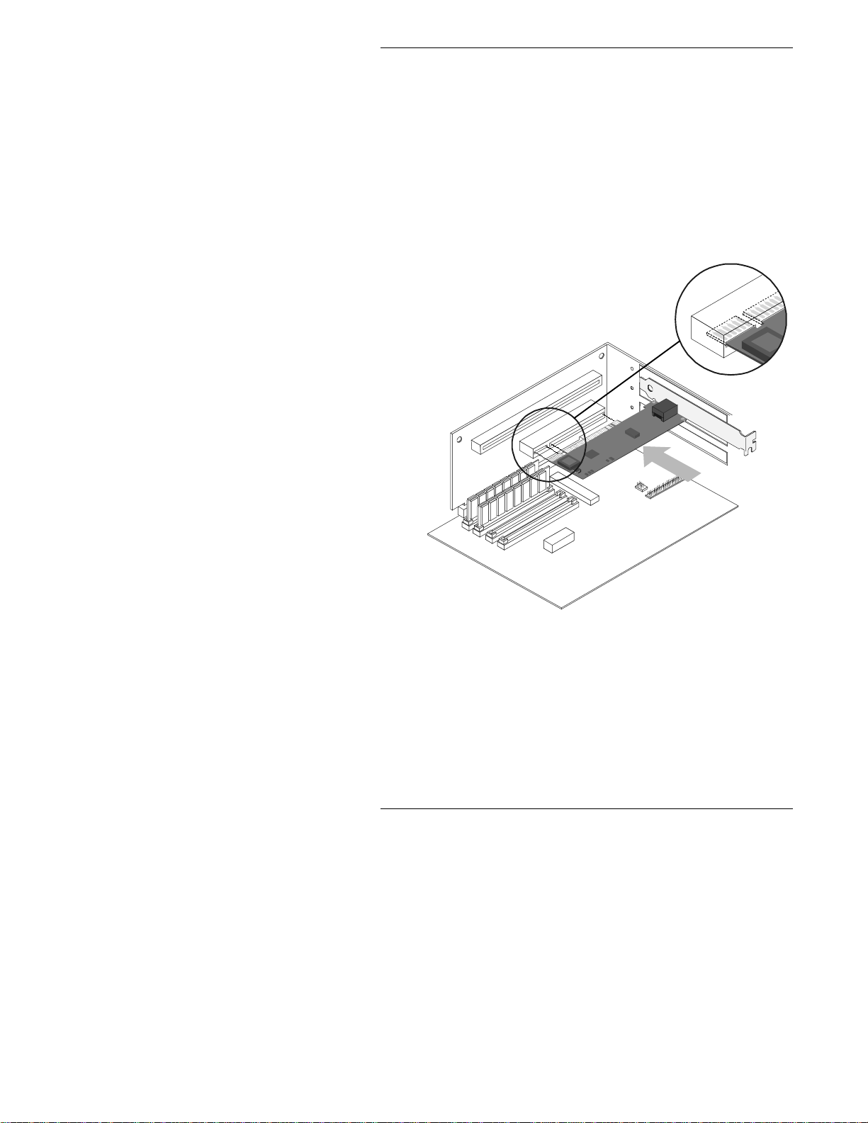
Chapter 3 Installing the Adapter in the N etServer
Figure 3-1. Inst al ling the Adapter in the HP NetServer
6
Page 15

4 Connecting the Network
Cable
1. Connect a Twisted Pair Ethernet (TPE) network cable to
the adapter as shown below.
• For 100BASE-TX, your network cable must be
Category 5, twisted- pair wiring. If you want to run
the adapter at 100 Mbps, it must be connected to a
100BASE-TX hub or switch (not a 100BASE-T4
hub).
• For 10BASE-T, use Category 3, 4, or 5 twisted-pair
wiring. If you want to use this adapter in a
residential environment, you must use a Category 5
cable.
NOTE Use a Category 5 TPE cable and a RJ-45
connector for this adapter. Do not use
Category 3 wiring a t 100 Mbps. At 100
Mbps, connect to a TX hub, not a T4 hub.
For full duplex, see the Duplex Mode section
later in this guide. For more information on
100BASE-TX wiring requirements an d
limitations, see the Fast Ethernet Wiring in
PCI Installation Tips section later in this
guide.
2. To configure the adapter, continue with the procedures
specific to your operating system outlined later in this
guide.
7
Page 16

Chapter 4 Connecting the Network Cable
Connect the Wake on LAN Power Cable
For the Wake on LAN (WOL) feature to work correctly, the
adapter must be connected to a continuous power source. This
allows the HP NetServer 10/100 adapter to “listen to” the
network even when the computer is turned off. To install the
WOL power cabl e, car efully follow the p rocedure below.
WARNING Turn off and unplug power to the computer
before installing the WOL cable. The WOL
conn ector on your motherboard is live when
the computer is plugged in to a power
outlet. Failure to do so could damage the
adapter or computer. Likewise, always
unplug the computer pri or to removing an
adapter from the computer.
1. Make sure your computer is unplugged from the power
outlet.
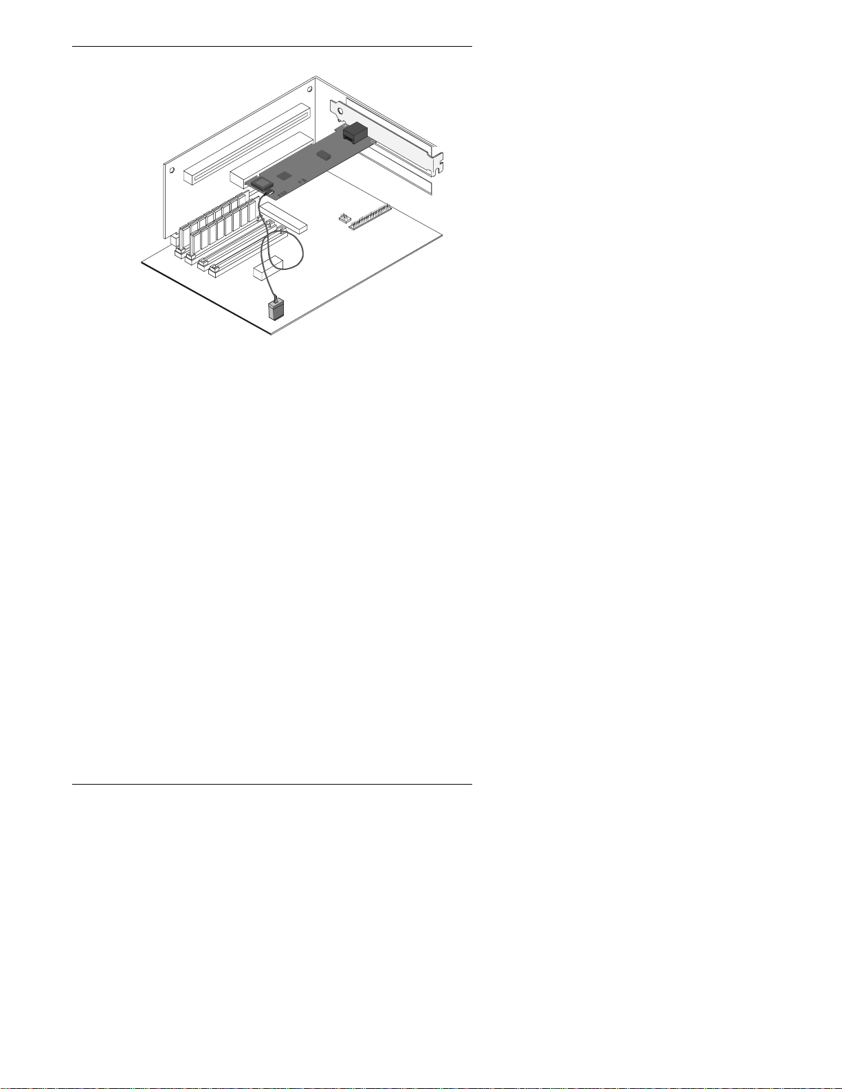
2. Locate the 3-pin WOL connector on the HP NetServer
10/100 adapter. Attach one end of the WOL cable to the
adapter as shown in Figur e 4-1.
NOTE The connect or is notched s o a s to preven t
incorrect attachment.
8
Page 17
Chapter 4 Connecting the Network Cable
Figure 4-1. Connecti ng t he Wake On LAN Cable
3. Locate the WOL connector on your m other boa rd. The
location varies, depending on the vendor and model of
motherboard. The WOL connector is usually located near
other power con nector s, such as th e LED conn ectors.
4. Connect the oth er end of t he WOL cable to the connector
on the motherboard as shown in Figure 4-1.
5. Some computers may require you to change a setting in
your computer’s BIOS or Setup program to enable the
WOL feature. Check your computer owner’s manual or
contact your dealer for more information.
6. Repl ace the com p uter cover and plug i n the power cord .
Using Wake on LAN
The Wake on LAN feature operates according to a published
specification. In simple terms, the specification allows
designers to build network adapters that are capable of
“listening” to network activity even when the computer is
turned off.
WOL adapters have a special low-power standby mode that is
active when the rest of the computer is without power. The
adapter will respond to a special “wake-up” packet sent by
9
Page 18

Chapter 4 Connecting the Network Cable
another computer or network device. Typically, this wake-up
packet causes the adapter to signal the computer to power up
and run a pre-defined program.
See th e Troubleshooting and FAQs section later in this guide
for general troubleshooting and a listing of common problems
and solutions for Wake on LAN operability.
Make a Setup Floppy Disk
If you need to use a floppy disk to install the adapter drivers,
use the MAKEDISK.BAT utility located in the ROOT directory
on the HP NetServer 10/100TX PCI LAN Adapter Drivers CD.
MAKEDISK [operating system] [destination]
where [operating system] is the OS for which you are creating
the diskette and [destination] is the drive letter and path (such
as A:).
The possible [operating system] options are:
W2K
= Microsoft Windows 2000
NT
= Micros oft Windows NT
10
NW
= Novell NetWare servers and clients
OS2
= IBM OS/2
UTIL
= DOS Diagnostics and i nformation
Page 19

5 Configuring the A dapter and
Installing Drivers
Novell NetWare 5.0 Only
Use the NetWare Install program to install the HP NetServer
10/100 adapter dri ver in Novell NetWare 5.0. For Novell
NetWare 4.1 x , see th e Novell NetWare 4.1x or 4.2 Only section
following this section. For Novell NetWare 3.11, 3.12 and 3.2,
see the ReadMe files. The following procedure is a condensed
description of the installation process:
1. From the NetWare console, type
Enter.
2. From the Configuration Options screen, choose Driver
Options an d press Enter.
3. Choose Configure network drivers and press Enter. If
any drivers are already loaded, a list of them appears.
4. Choose Select an additional driver and press Enter. A list
of drivers appears.
5. Insert t he HP NetServer 10/100TX PCI LAN Adapter
Drivers CD into the CD-ROM drive and press the Insert
key to install an unlisted driver.
6. To specify the correct path to your media (if necessary),
press F3. Press Enter to search th e floppy or CD-ROM
drive. To install from the CD, type the CD Volume Name:
\NetWare Server Name. For example,
HPTX_PCI_A+:\NWSERVER.
7. Select the appropriate HP PCI LAN Adapter and press
Enter.
8. Respond to the Copy and Save prompts.
9. Use the arrow keys to select additional protocol types, F3
to manually set IPX Frame types, or choose the defaults.
10. Enter the slot number. (You can find the slot number by
switching to the Console and manually loading the driver.
A list of available slot numbers is displayed. Then abort
NWCONFIG
and press
11
Page 20

Chapter 5 Configuring the Adapter and Installing Drivers
(press Esc) the manual install and return to the NWConfig
screen.)
11. Select Save parameters and load driver to continue.
12. For each additional adapter you want to install, respond to
the prompt and t hen repeat steps 7-11.
13. To complete the driver installation process, press the Esc
key until you arrive back at the Installation Options screen.
14. To ret urn to the console prompt, choose Exit.
NOTE If the adapter cannot transmit or receive
following the installation, you may need to
modify the frame type in the
AUTOEXEC.NCF
file.
Novell NetWare 4.1x or 4.2 Only
Use the NetWare install program to install the HP NetServer
10/100 adapter dri ver in Novell NetWare 4.1x. For Novell
NetWare 3.11, 3.12 and 3. 2, see the ReadMe files. The
following procedure is a condensed description of the
installation process:
NOTE Prior to installing, either load DOS or
NetWare drivers from your computer’s
CD-ROM drive or create a floppy disk from
the HP NetServer 10/100TX PCI LAN
Adapter Drivers CD using the
MAKEDISK.BAT
Setup Floppy Disk section earlier in this
guide.
1. From the NetWare console, type
press Enter.
2. From the Installation Options screen, choose Driver
options and press Enter.
3. Choose Configure network drivers and press Enter. If
any drivers are already loaded, a list of them appears.
4. Choose Select an additional driver and press Enter. A
12
utility. See the Making a
LOAD INSTALL
and
Page 21

Chapter 5 Configuring the Adapter and Installing Drivers
list of drivers appears.
5. Insert t he HP NetServer 10/100TX PCI LAN Adapter
Drivers CD into the CD-ROM drive and choose Install an
unlisted driver by clicking Insert.
6. If necessary, specify the correct p ath to your medi a by
pressin g F3. Press Enter to search the floppy or CD-ROM
drive.
7. The driver name is displayed: HP NetServer 10/100
adapter. Press Enter to select it.
8. The next screens ask for frame and protocol types. Use the
arrow keys to select sp ecific items or choose the defaults.
Select Save parameters and load driver to continue.
9. For each additional adapter you want to install, press Esc,
and then repeat steps 7-8.
10. To complete the driver installation process, press the Esc
key until you arrive back at the Installation Options screen.
11. To ret urn to the console prompt, choose Exit.
NOTE If the adapter cannot transmit or receive
following the installation, you may need to
modify the frame type in the
AUTOEXEC.NCF
file.
Windows 2000
Install Networ k Driv ers from Disk
After you put the HP NetServer 10/100 adapter i n the
comput er, con nect the network cable, plug in t he power cor d
and start the computer. Windows automatically installs a
driver for the adapter from its own library of drivers. However,
you should still install the driver that is included on the HP
NetServer 10/100TX PCI LAN Adapter Drivers CD to ensure
you have the complete set of features described in this guide.
You can install this driver manually using the following
instructions:
1. Insert t he HP NetServer 10/100TX PCI LAN Adapter
Drivers CD in th e CD-ROM drive. (If the HP Product
13
Page 22

Chapter 5 Configuring the Adapter and Installing Drivers
Setup Autorun screen appears, you may close it.)
2. From the Control Panel, double-click the System icon,
select the Hardware tab, and click the Device Manager
button.
3. Select “Network Adapters” and right-click on the HP
NetServer 10/100 adapter listing t o display its menu. Th en
click the Properties menu option.
4. From the Properties dialog box, click the Driver tab and
click the Update Driver button. The Upgrade Device
Driver Wizard appears. Click Next.
5. At the prompt “What do you want the wizard to do?" select
the “Search for a suitable driver for my device” radio
button and click Next.
6. Sel ect the C D - ROM d rives ch eck box and click Next.
7. Select the “Install one of the other drivers” check box and
click Next.
8. Sel ect the d river on th e HP NetServer 10/100TX PCI LAN
Adapter Drivers CD and click Next.
9. Restart your computer.
After restarting your computer, connect to your network by
double-clicking My Network Places icon on the desktop.
Windows NT Automatic Configuration
PCI computers automatically detect and configure
PCI-compliant adapters while starting the computer. The
adapter IRQ level and I/O address are automatically set by the
BIOS each time you start your server.
Start your server to automatically configure the adapter.
Configuration is complete when Windows NT starts or when
the DOS prompt appears.
If your server displays an error while booting, it may require
additional steps to configure. See the PCI Installation Tips
section later in this guide for more information.
14
Page 23

Chapter 5 Configuring the Adapter and Installing Drivers
Adding an A dapter while I nstalling Win dows NT
The HP driver that ships with Windows NT 4.0 is an older
driver that does not support this ada pt er .
Therefore if you want to install the HP NetServer 10/100
adapter while installing Windows NT, you need to install the
adapter after the installation of Windows NT is complete or
install the adapter software from a floppy installation disk
created from the HP NetServer 10/100TX PCI LAN Adapter
Drivers CD (using the
CD).
MAKEDISK.BAT
file on the root of the
Windows NT Version 4.0 Only
After putting the adapter in the server, connecting the cable,
and starting Windows NT, you need to install the correct
drivers.
1. Double-click the Network icon in Control Panel.
2. Click the Adapters tab.
3. Click Add. You’ll see a list of adapters.
4. Don’t select an adapter from this list. Instead, insert the
HP NetServer 10/100TX PCI LAN Adapter Drivers CD
into the appropriate drive and click Have Disk.
5. Specify the appropriate drive in the dialog box and click
OK. Then follow the prompts to complete installation.
When the adapter is added you’ll see a new adapter listed
in the Network adapters list.
6. Click Close to finish.
7. Restart Windows NT when prompted.
Windows NT Version 3.51 On ly
After putting the adapter in the server, connecting the cable,
and starting Windows NT; you need to install the correct
drivers.
1. Double-click the Network icon in Control Panel.
2. Click Add Adapter.
15
Page 24

Chapter 5 Configuring the Adapter and Installing Drivers
3. When the list of adapters appears, scroll to the end of the
list and select <Other> Requires disk from
manufacturer, then click Continue.
4. Insert t he HP NetServer 10/100TX PCI LAN Adapter
Drivers CD in the appropriate drive, specify th at drive,
then click OK.
5. Sel ect the HP NetServer adapter, and then click OK.
Drivers and utilities are installed.
6. The TCP/IP Configuration dialog box appears. Enter the
appropriate information and click OK. Remove the HP
NetServer 10/100TX PCI LAN Adapter Drivers CD.
7. Wh en pr om p ted, restart Windows NT.
NOTE For troubleshooting information, see the
next section, Windows NT Troubleshooting.
Windows NT Troubleshooting
If Windows NT reports an error or you can’t connect to the
network, try the suggestions here first, then turn to the
Troubleshooting and FAQs section later in this guide, if
necessary.
1. Make sure that you use the drivers for this adapter. Drivers
are located on the HP NetServer 10/100TX PCI LAN
Adapter Drivers CD.
2. In your computer’s BIOS settings, make sure “Plug and
Play OS” is set to NO.
3. Make sure the driver is loaded and the protocols are bound.
Check the Settings in the Control Panel’s
Network/Bindings dialog box.
4. Check the Win d ows NT Event Viewer for error messages.
5. If you are attaching to a NetWare network, check your
frame type and verify that NetWare client or server
software has been installed.
6. Test the adapter with the HPSet advanced configuration
utility that was installed on your system when you installed
the HP NetServer 10/100 adapter . To star t HPSet,
16
Page 25

Chapter 5 Configuring the Adapter and Installing Drivers
double-click the HPSet icon in the Windows Control
Panel. To run diagnostics, select the adapter and click the
Diagnostics tab, then click Run Tests. For additional
information, click Help in the HPSet window.
7. Check with your LAN administrator — you may need to
install supplemental networking software.
UNIX, Banyan VINES, and Other
Operating Systems
Refer to the onli ne documents. On a DOS computer, view the
appropriate ReadMe file for information on installing your
network driver.
To view the ReadMe files go to the \INFO folder and use a t ext
editor such as Notepad.
HPSet: An Overview
When you install the HP NetServer 10/100 adapter Windows
drivers, an advanced configuration utility called HPSet is also
installed. Users running Windows 2000 or NT can easily test
hardware and set standard and advanced adapter features with
HPSet. HPSet runs when you select an adapter and click the
Properties button in the Network Control Panel.
17
Page 26

Chapter 5 Configuring the Adapter and Installing Drivers
Figure 5-1. HPSet f or Windows NT
Priority Packet: An Overview
Priority Packet is a traffic-prioritization utility that enables you
to set up priority filters to process high priority traffic before
normal traffic. Using Priority Packet, you can give priority to
critical applications or users.
Priority Packet is available on the HP NetServer 10/100TX PCI
LAN Adapter Drivers CD in the \Priority Packet di rector y.
Prioritizin g Network Traffic
Priority Packet lets you set up priority filters to send
information from critical nodes or applications with an
indicated priority. By prioritizing traffic at the host or entry
point of the network, network devices can base forwarding
decisions on priority information defined in the packet.
Priority Packet prioritizes traffic based on priority filters —
parameters you assign to be applied to outgoing (transmit)
packets. Using the Priority Filter Wizard, you can set up
pre-defined or custom priority filters based on a node (MAC)
addres s , Ethern e t type, or by various properti e s of the prot oc ol
18
Page 27

Chapter 5 Configuring the Adapter and Installing Drivers
and port. Priority Packet provides two different methods for
prioritizing traffic: IEEE 802.1p tagging and High Priority
Queue.
IEEE 802.1p Tagging
IEEE 802.1p is a new IEEE standard for tagging, or adding
additional bytes of information to, packets with different
priority levels. Packets are tagged with four additional bytes,
which increase the packet size and indicate a priority level.
When these p ackets a re sent out on the n etwork, the high erpriority packets are transferred first. Priority packet tagging
(also known as Traffic Class Expediting) allows the adapter to
work with other elements of the network (switches, routers) to
deliver priority packets first. 802.1p tagging enables you to
assign specific priority levels from 0 (low) to 7 (high).
Using the IEEE 802.1p standard for packet tagging, you can
assign values to packets based on their priority. This method
requires a network infrastr ucture that supports packet tagging.
The routi ng devices receiving and trans ferri ng these pack ets on
your network must support 802.1p for tagging t o be effective.
After you set up the priority filter in Priority Packet, you must
launch HPSet and select 802.1p/802.1Q Tagging on t he
Advan ced tab.
CAUTION IEEE 802.1p tagging increases the size of
the packets it tags. Some hubs and switches
won’t recognize the larger packets and will
drop them. Check your hub or switch
documentation to see if it supports 802.1p.
(You can configure the switch to strip the
tags from the packets and send it on to the
next destination as normal traffic.) If these
devices don’t support 802.1p or you’re not
sure, use High Prior i t y Queue (HPQ) to
prioritize network traffic.
19
Page 28

Chapter 5 Configuring the Adapter and Installing Drivers
The requirements for effectively using IEEE 802.1p tagging
are:
• The oth er devices receiving and rou t ing 802. 1p
tagged packets must support 802.1p.
• The adapters on these devices must support 802.1p
(adapters using the 82558 or later Ethernet
controller). All HP NetServer 10/100 adapters
support 802.1p.
• The adapter(s) cannot be assigned to an adapter
team.
• If you’re setting up VLANs and packet ta g ging on
the same adapter, you must select the 802.1p/802.1Q
Tagging and the Enable option on the HPSet
Advan ced tab.
High Priority Queue
If your network infrastructur e devices don’t support IEEE
802.1p or you’re not sure, you can still define priority filters
and send packets as high priority. While High Priority Queue
(HPQ) doesn’t provide the precise priority levels of 802.1p
tagging, it does assign traffic as either high or low priority, and
sends high priority packets first. Therefore, if there are multiple
applications on a system sending packets, the packets from the
application with a priority filter are sent out first. HPQ doesn't
change network routing, or add any information to the packets.
To assign HPQ, you can specify it using Priority Packet when
you create or assign a priority filter.
To effectively use HPQ tagging, the adapter(s) cannot be
assigned to an adapter team.
20
Page 29

6 Installing Multiple Adapters
The adapter’s 12-digit, hexadecimal Ethernet address is printed
on a sticker placed on the adapter. The Ethernet address is
sometimes called the node address or the MAC address. Note
that the PCI slot number may not correspond with the physical
conn ector in your NetServer.
NetWare Users
The s erver driver s use th e PC I slot number to iden t ify each
installed adapter. You can correlate the PCI slot number to the
adapter by using the Ethernet address that is printed on a label
on the adapter. Run Setup to view th e Ethernet address and slot
number for each installed adapter. For more information, see
the ReadMe files.
Windows NT 3.51 Users
Repeat the configuration procedure for each adapter you want
to install.
21
Page 30

Page 31

7 Selecting Duplex Mode
(Optional)
Duplexing is a performance option that lets you choose how the
adap ter sends and receives data packets over the network. The
adapter can operate at full duplex only when connected to a full
duplex 10BASE-T or 100BASE-TX switch, or to another full
duplex adapter.
The possible settings for duplexing are:
• Auto (requires a full duplex adapter or switch with
auto-negotiation capability). The adapter negotiates
with the swit ch to send an d receive pa ck ets at the
highest rate. This is the default setting. If the switch
does not provide auto-negotiation, the adapter runs
at half duplex.
• Full duplex (requires a full duplex switch or
adap ter). Th e adapt er can send and receive packets
at the same time. This mode can increase adapter
performance capability. If the full duplex switch
provides auto-negotiation, the adapter runs at full
duplex. If the full duplex switch does not provide
auto-negotiation, you need to set the adapter duplex
mode manually (see the following sections), because
it defaults to half duplex.
• Half duplex. The adapter performs one operation at
a time; it either sends or receives.
NOTE If an adapter is running a t 100 Mbps and
half-duplex, your potential bandwidth is
higher than if you run it at 10 Mbps and full
duplex.
23
Page 32

Chapter 7 Selecting Duplex Mode (Optional)
Manually C onfiguring for Full Duplex
If your switch supports auto-negotiation with the NWay
standard, duplex configuration is automatic and no action is
required on your part. However, many currently installed
switches do not support auto-negotiation. Check with your
network system administrator to verify whether your switch
supports this feature. Most installations require manual
configuration to change to full duplex.
Configuration is specific to the driver you’re loading for your
network operating system (NOS).
To set up the duplex mode, refer to the section below that
corresponds to your operating system.
CAUTION Adapter performance may suffer or your
adapter may not operate if your switch
doesn’t support full duplex and you
configure the adapter to full duplex. The
switch settings must always agree with the
adapter. Also, make sure to always set the
speed when you configure duplex.
Setting Full Du plex in Win dows NT/2000
While running Windows:
1. Double-click the HPSet icon from the Control Panel.
2. Click the Advanced Tab.
3. Select Duplex.
4. In the Duplex Mode list box, click Full Duplex.
5. Click OK.
6. Restart Windows.
Setting Full Du plex in NetWar e Serv ers
For each adapter in
command and add the following options (you must include the
equal sign for servers):
24
AUTOEXEC.NCF
, edit the LOAD
Page 33

Chapter 7 Selecting Duplex Mode (Optional)
FORCEDUPLEX=2
SPEED=100
(or 10 if 10BASE-T)
For more information, see the ReadMe file for NetWare
servers.
Setting Full Duplex in Oth er Operating S ystems
See th e
the HP NetServer 10/100TX PCI LAN Adapter Drivers CD.
Open the file with any text editor.
OTHER.TXT
ReadMe file in the \OTHER directory on
Join a Virtual LAN
A Virtual LAN (VLAN) is a logical grouping of network
devices put together as a LAN regardless of their physical
grouping or collision domains. VLANs let a u ser see an d access
only specified network segments. This increases network
performance and improves network security.
VLANs offer the ability to group users and stations together
into logical workgroups. This can simplify n etwork
administration when connecting clients to servers that are
geographically dispersed across the building, campus, or
enterprise network.
Switch with IEEE 802.1Q
VLAN capability
T runk
Comm o n server with a
PRO/100 A dapter
VLANs 10, 20 , & 30
Engineering
1st floor
VLAN 30
Customer Support
1st floor
VLAN 10
Engineering
2nd floor
VLAN 30
Figure 7-1. Vi r t ual LAN Configurati on
Typically, VLANs consist of co-worker s wit hin t he same
department but in different locations, groups of users running
the same network protocol, or a cross- functional team working
25
Page 34

Chapter 7 Selecting Duplex Mode (Optional)
on a joint p roject. Joining workers with VLANs form s l ogi ca l
working groups.
VLANs are normally only configurable at the switch. However,
the HP NetServer 10/100 adapter software permits you to
configure a NetWa re server with up to 64 VLANs, and 55
VLANs for Windows NT 4.0.
To set up VLAN membership, your adapter must be attached to
a switch with VLAN capability.
For more information on VLANs in NetWare, see the
NWTEAM.TXT
Adapter Drivers CD.
For more information on VLANs in Windows NT, con t i nue to
the next section.
file on the HP NetServer 10/100TX PCI LAN
General Configuration Notes
1. Wind ows NT versions pri or t o 4.0 don’t suppor t VLANs.
2. VLANs requir e Win d ows 2000 or Windows NT 4.0 with
Service Pack 4.0 (or later).
3. In Windows NT and Windows 2000, VLANs cannot be
implemented on adapters that have been configured for
teaming options.
4. 802.1p/802. 1q i s required for VLANs to function. You can
enable this feature through the Advanced tab in HPSet.
5. HP NetServer 10/100 adapters only support VLANs
configured in compliance with the IEEE 802.1q
specification. No support for ISL (Inter-Switch Link)
VLANs is int ended.
A dding a VLAN in Windows NT 4.0
1. Create a VLAN on the switch. Use the parameters you
assig n there to joi n th e V LAN from the server. See your
switch documentation for more information.
2. Double-click the Network icon in Control Panel.
3. On the Adapters tab, select the adapter you want to be on a
VLAN and cli ck Properties.
4. In HPSet, click Join VLAN. Note that VLANs cannot be
26
Page 35

Chapter 7 Selecting Duplex Mode (Optional)
assigned to adapters that are already in an Adapter
Teaming option.
5. Enter the VLAN ID and VLAN Na m e. The VLAN ID
must match the VLAN ID on the switch. Valid ID range is
from 0-4095. The VLAN Name is for informational
purposes only and doesn’t have to match the name on the
switch.
6. Click Join VLAN. Repeat steps 3-5 for each VLAN you
want the server to join. The VLANs you add are li sted on
the Adapters tab.
7. Click Close and restart the computer.
A dding a VLA N in Windows 2000
IMPORTANT You must use HPSet to add or remove a
VLAN in Windows 2000. Do not use the
Network and Dial-up Connections dialog
box to enable or disable VLANs. Ot herwise,
the VLAN driver may not be correctly
enabled or disabled.
1. Create a VLAN on the switch. Use the parameters you
assig n there to joi n th e V LAN from the server. See your
switch documentation for more information.
2. In HPSet, click the Virtual LAN tab. Note that VLANs
cannot be assigned to adapters that are already in an
Adapter Team.
3. Under the Virtual LAN tab, click the ADD button.
4. If this is the first VLAN you're creating, you may see the
following message: "In order for VLANs to functi on , you
must be connected to a switch which supports IEEE
VLANs (802.1Q). Also, 802.1p/802.1Q T a ggi ng must be
enabled on this adapter. Would you like to enable
802.1p/802.1Q Taggin g on t his adapter?" If this message
appears, click Yes to continue. HPSet will automatically
enable the 802.1p/802.1Q feature on the Advanced tab.
5. Enter the VLAN ID and VLAN Name and click OK.
6. The VLAN ID must match the VLAN ID on the switch.
Valid ID range is from 1-4094. The VLAN Name is for
27
Page 36

Chapter 7 Selecting Duplex Mode (Optional)
informational purposes only and doesn’t have to match the
name on the switch.
7. Repeat step s 3 and 5 for each VLAN you want the server t o
join. 802.1p/ 802.1q is enabled for all VLANs after it is
enabled for the first VLAN. The VLANs you add are li st ed
on the Adapters tab.
8. At the Virtual LAN tab, click OK and restart the
computer.
28
Page 37

8 Choosing A dapter Teaming
Options
The HP NetServer 10/100 adapter provides several options for
increasing throughput and fault tolerance when running
Windows 2000, Windows NT 4.0 or NetWare 4.2 or newer:
NOTE Use of the teaming features requires HP
Server adapters.
Adapter Fault Tolerance (AFT) — provides automatic
redundancy for your adapter. If the primary adapter fails, the
secondary takes over. Adapter Fault Tolerance supports two to
eight adapters per team.
Adaptive Load Balancing (ALB) — allows balancing the
transmission data flow among two to eight adapters. Also
includes the AFT option. Works with any 100BASE-TX
switch.
Cisco Fast Ether Cha nne l ( FEC) — creates a team of two,
four, six or eight adapters to increase transmission and
recept ion throug hput . Also includ es A F T option. Requi res a
switch with FEC capability. (See your switch documentation
for the number of ports you can aggregate in a team.)
To set up an option, go to the appropriate section in the pages
that follow.
General Configuration Notes
• Windows NT versions prior to 4.0 don’t support
adapter teaming options.
• Adapter Teaming options require Windows NT 4.0
with Service Pack 4 or high er.
29
Page 38

Chapter 8 Choosing Adapter Teaming Options
Setting up Adapter Fault Tolerance
NOTE Use this procedure for setting up AFT only.
If setting up ALB or FEC, use the
procedu res in th e next sections. Th e AF T
feature runs automatically when you enable
ALB or F EC.
Adapter Fault Tolerance (AFT) provides the safety of an
additional backup link between the server and buffered repeater
or switch. In the case of a buffered repeater or switch port,
cable, or adapter failure, you can maintain uninterrupted
network performance through an adapter team.
AFT is implemented with a primary adapter and one or more
backups, or secondary adapters. During normal operation, the
backup adapters are in standby. If the link to the primary
adapter fails, the link to the secondary adapter takes over.
Setting up Adapter Fault Tolerance in
Windows NT 4.0
1. See software requirements for AFT in the previous section,
General Configuration Notes.
2. Double-click the Network icon in Control Panel.
3. On the Adapters tab, select a HP NetServer 10/100 adapter
that will be in the team and click Properties. (Don’t use an
adapter that is on a VLAN.)
4. In the HPSet win dow, click the Adapter Teami ng tab.
5. Click the Add Adapter to a Tea m button.
6. The Teaming Wizard starts. Follow the wizard steps for
assigning ada pt ers to a team. AFT supports up to eight
adapters per team, in any combination. Note that you can
specify a Preferred Primary adapter, which in most cases
will be your highest bandwidth adapter. See the HPSet
Help for more information.
7. Click OK, then click Close to finish. Wh en pr om p ted,
restart your computer.
30
Page 39

Chapter 8 Choosing Adapter Teaming Options
Configuring Properties
The default AFT properties are suitable for most applications.
To adjust them, follow this procedure.
1. Run HPSet.
2. On the adapter list, select the desired AFT team.
3. Click the Advanced Setting s tab.
4. Adjust parameters as required. Click Help for more
information.
Deleting a Team
1. Double-click the Network icon in Control Panel.
2. On the Adapters tab, select the AFT team to delete.
3. Click Remove. A confirmation dialog box appears. Click
Yes.
4. Click Close. Restart W indows NT when prompted.
NOTE When IPX is used, the frame type for each
adapter in the team reverts to Auto when a
team is deleted. You may need to set it to the
specific frame type to connect to your
network.
Setting up Adapter Fault Tolerance in
NetWare
1. Copy the following l i nes from th e E XAMPLES.TXT file
(on the HP NetServer 10/100TX PCI LAN Adapter Drivers
CD), paste them into the appropriate files, and modify
them. These commands assume the
CHPTX.LAN
SYS:SYSTEM
(
the HP NetServer 10/100TX PCI LAN Adapter Drivers CD
to your server’s hard dr i ve).
files are in the system directory
) of your server. (Files must be copied from
HPANS.LAN
and
31
Page 40

Chapter 8 Choosing Adapter Teaming Options
NOTE The
HPANS.LAN
driver requires more
resources (memory) than a traditional LAN
driver. To accommodate this, the minimum
and maxi mum pa ck et recei ve buffer s need to
be increased. The exact numbers depend on
the complexity of the team; however, the
following settings (which are to be added to
STARTUP.NCF
the
file) should be sufficient
for most sing l e t ea m systems.
Copy th ese lines into the STARTUP.NCF file
SET MINIMUM PACKET RECEIVE
BUFFERS=500
SET MAXIMUM PACKET RECEIVE
BUFFERS=2000
Copy th ese lines into the AUTOEXEC.NCF file
;- Load the base driver for each adapter
where x is the primary adapter’s slot
number and y is the secondary adapter’s
slot number.
load CHPTX slot=x name=primary
load CHPTX slot=y name=secondary
Do not bind protoc ols to the base (CHPTX) dr iver .
;- Load HPANS to form the basis of a team
load HPANS
;- Bind HPANS to each physical adapter
bind HPANS CHPTX primary
bind HPANS CHPTX secondary
;- Use HPANS to commit the team where z is
the teaming mode of your choice: Specify
AFT for Adapter Fault Tolerance, ALB for
Adaptive Load Balancing, or FEC for Fast
Ether Channel.
load HPANS commit mode=z
32
Page 41

Chapter 8 Choosing Adapter Teaming Options
;- Bind the protocol to HPANS instead of to
the base driver
bind ipx HPANS net=1
Variable Definitions:
slot= the slot number your HP NetServer 10/100 adapter is
installed in, such as 1. If you don’t know the number, load the
driver without it. NetWare will prompt you with available PCI
device n u mbers.
Note that you can specify a Preferred Primary adapter, which in
most cases will be your highest bandwidth adapter. See the
NW411.TXT file on the CD for more information.
2. Modify the lines to match your server’s requirements.
3. Save the
AUTOEXEC.NCF
file and restart your server.
Deleting a Team
To remove a team in AFT or ALB mode, comment out the
command lines above and restart the server .
Setting up Adaptive Load Balancing
Adaptive Load Balancing (ALB) is a simple and efficient way
to balance the transmission load of your server among two to
eight adapters. With ALB, you group HP NetServer 10/100
adapters in teams. The ALB software continuously analyzes
transmit loading on each adapter and balances the rate across
the adapters as needed. Adapter teams configured for ALB also
provid e the ben efi ts of AFT. Recei ve data is not load-balanced.
NOTE For maximum benefit, ALB should not be
used under NetBEUI and some IPX
environments. For a list of specific IPX
environments supported, see the Teaming
Options Supported by OS and Protocol
section later in this guide.
To use ALB, your adapters must be configured as a team in
your server and be connected to the same switch.
33
Page 42

Chapter 8 Choosing Adapter Teaming Options
Setting up ALB in Windows NT 4.0
1. Double-click the Network icon in Control Panel.
2. On the Adapters tab, select an adapter that will be in the
team, and then click Properties. (Don’t use an adapter that
is on a VLAN.)
3. In the HPSet window, click the Adapter Teaming tab.
4. Click the Add Adapter to a Tea m button.
5. The Teaming Wizard starts. Follow the wizard steps for
assigning adapters to a team. Note that you can specify a
Preferred Primary adapter, which in most cases will be
your highest bandwidth adapter. See the HPSet Help for
more information.
6. Click OK, then click Close to finish. Wh en pr om p ted,
restart your server.
Deleting a Team
1. Double-click the Network icon in Control Panel.
2. On the Adapters tab, select the ALB team to delete.
3. Click Remove. You’ll see a confirmation dialog box. Click
Yes.
4. Click Close. Restart when prompted.
NOTE When IPX is used, the frame type for each
adapter in the team reverts to Auto when a
team is deleted. You may need to set it to the
specific frame type to connect to your
network.
Setting up ALB in NetWare
To set up ALB in NetWare, use the instructions in the Setting
up Adapter Fault Tolerance in NetWare section earlier in this
guide, substituting “ALB” for the “Z” parameter.
34
Page 43

Chapter 8 Choosing Adapter Teaming Options
Setting Up Cisco Fast EtherChannel
Fast EtherChannel (FEC) is a performance technology
developed by Cisco to increase throughput between switches.
HP has implemented FEC on server adapters to increase your
server’s throughput. Unlike ALB, FEC can be configured to
increase both tr ansm ission and recepti on cha nnel s bet ween
your server and switch. FEC works only with FEC-enabled
Cisco switches, such as the Catalyst 5000 series. With FEC, as
you add adapters to your server, you can group them in teams to
provide up to 800 Mbps at full duplex, with a maximum of
eight HP NetServer 10/100 adapt ers. (Note that the switch must
support more than four adapter s in FEC in order for more than
four adapters to work in FEC. Consult your switch
documentation.) The FEC software continuously analyzes
loading on each adapter and balances network traffic across the
adapters as needed. Adapter teams configured for FEC also
pr ovide t he benefits of AFT.
To use FEC, you must have two, four, six or eight HP
NetServer 10/100 adapters configured as an FEC Team in your
server or workstation and linked to the same FEC-enabled
Cisco switch.
Setting up FEC in Windows NT 4.0
1. Double-click the Network icon in Control Panel.
2. On the Adapters tab, select a HP NetServer 10/100 adapter
that will be in the team and click Properties. (Don’t use an
adapter that is on a VLAN.)
3. In the HPSet win dow, click the Adapter Teami ng tab.
4. Click the Add Adapter to a Tea m button.
5. The Teaming Wizard starts. Follow the wizard steps for
assigning adapters to a team. Note that you can specify a
Preferred Primary adapter, which in most cases will be
your highest bandwidth adapter. See the HPSet Help for
more information.
6. Click OK, then click Close to finish. Wh en pr om p ted,
restart your computer.
35
Page 44

Chapter 8 Choosing Adapter Teaming Options
Deleting a Team
1. Double-click the Network icon in Control Panel.
2. On the Adapters tab, select the FEC team to delete.
3. Click Remove. A confirmation dialog box appears. Click
Yes.
4. Click Close. Restart when prompted.
NOTE When IPX is used, the frame type for each
adapter in the team reverts to Auto when a
team is deleted. You may need to set it to the
specific frame type to connect to your
network.
Setting up FEC in NetWare
To set up FEC in NetWare, use the instructions in the Setting
up Adapter Fault Tolerance in NetWare section earlier in this
guide, substituting “FEC” for the “Z” parameter.
Teaming Options Supported by OS and
Protocol
Windows NT 4.0 NetWare 4.2, 5.0, 5.1
AFT
ALB
FEC
Note that on ly IPX packets type NCP (NetWare Core Protocol)
are load balanced. Under FEC, all protocols can be load
balanced.
36
IP, NetBEUI, IPX(NCP) ,
IPX (NetBIOS)
IP, IPX (NCP) IP, IPX (NCP)
IP, NetBEUI, IPX (NCP),
IPX (NetBIOS)
IP, IPX (NCP),
AppleTalk
IP, IPX (NCP)
Page 45

9 Troubleshooting and FA Qs
If the A dapter Can’t Connect to the
Network
Make sure th e cable is installed pr operly .
The network cable must be securely attached at both RJ-45
connections (adapter and hub). The maximum allowable
distance from adapter to hub is 100 meters. If the cable is
attached and the distance is within acceptable limits but the
problem persists, try a different cable.
If you’re directly connecting two servers without a hub or
switch , use a crossover cabl e.
Check the LED lights on the adapter.
The adapter has two diagnostic LEDs, one on each side of the
cable con nector. Th es e ligh ts hel p indicate i f t here’ s a problem
with the con nector, cable, or switch/h u b.
Responder Testing on the Netw ork (Option al)
Setup can test the adapter more thoroughly if there is a
responder on the network while you run the tests.
1. Go to a NetServer on the network with a compar able PCI
adapter installed.
2. Run the appropriate configuration program for the
installed adapter and set it up as a responder.
3. Return to the server that has the new adapter. Run Setup
and test the adapter by running diagnostics.
37
Page 46

Chapter 9 Troubleshooting and FAQs
LED Function Indicators
LED Meaning
ACT/LNK
On
ACT/LNK
Off
The adapter and swit ch ar e receiving power; the cable
connection between the switch and adapter is good.
The adapter and swit ch ar e not r eceiving p ower or th ere
is a driver configuration problem.
If the LED is off:
•
Make sur e power is con nected to the PC . If power is
connected and the LED is still off:
•
Make sure the WOL cable is attached and power is
applied to the computer.
•
Make sure the network cable is attached at both ends.
•
Make sure you’ve loaded the network drivers.
•
Check all connections at the adapter and the switch an d
make s u re both ends are connected.
•
Try another port on the switch.
•
Make sure the duplex mode setting on the adapter
matches the setting on the switch.
•
Make sur e you h ave the correct type of cable between the
adapter and t he hub. 100BASE-TX requires two pairs.
Some hubs require a crossover cable, while others
require a straight-through cable.
•
Make sur e you’ve l oa d ed the cor rect network driver s .
ACT/LNK
Flashing
The adapter is sending or receiving n et work data. The
frequency of the flashes varies with the amount of
network traffic.
If the ACT/LNK LED does not flash, the cause could be:
•
The network may be idle. Try accessing a server.
•
The adapter may not be transmitting or receivin g d ata.
Try another adapter.
•
Make sure you’re using two-pair cable for TX wiring.
100 On Operating at 100 Mbps.
100 Off Operating at 10 Mbps.
38
Page 47

Chapter 9 Troubleshooting and FAQs
Make sure y ou’r e usin g the corr ect driv ers.
Make sure you’re using the drivers that come with this adapter.
Drivers that support pr evious versions of this adapter don’t
support this version of the adapter.
Make sure th e switch por t and the adapter hav e the
same duplex setting.
If you configured the adapter for full duplex, make sure the
switch port is also configured for full duplex. Setting the wrong
duplex mode can degrade performance, cause data loss, or
result in lost connections.
Testing the A dapter (Diagnostics)
Test th e a dapter by running d i a g nostics. For DOS or Wi ndows
3.1, run Setup on th e HP NetServer 10/100TX PCI LAN
Adapter Drivers CD. For Wind ows NT, run HPSet by doubleclicking the HPSet icon in the Windows Control Panel. To run
diagnostics, select the adapter and click the Diagnostics tab,
then click Run Tests. For additional information, click Help in
the HPSet window.
Frequently Asked Questions (FAQs)
Setup.exe reports the adapt er is “Not enabled by BIOS.”
•
The PCI BIOS isn’t configuring the adapter correctly. See
PCI Installation Tips earlier in this guide.
The server hangs when the driver s ar e l oaded.
•
Change the PCI BIOS interrupt settings. See PCI Installation
Tips for more information.
•
If you are using EMM386, it must be version 4.49 or newer
(this version ships with MS-DOS 6.22 or newer).
Diagnostics pass, but t he connect i on f ails or errors
occur.
•
At 100 Mbps, use Category 5 wiring and make sure the
network cable is securely attached.
39
Page 48

Chapter 9 Troubleshooting and FAQs
•
At 100 Mbps, connect to a 100BASE-TX hub/switch (not
100BASE-T4).
•
For NetWare, make sure you specify the correct frame type in
your NET.CFG file.
•
Make sure the duplex mode setting on the adapter matches
the setting on the switch.
The adapter stopped working without apparent cause.
•
Run the diagnostics.
•
Try reseating the adapter in its slot, or try a different slot if
necessary.
•
The network driver files may be corrupt or missing. Remove
the drivers and then reinstall them.
The Wake on LAN feature is not w or king.
•
Make sure the WOL cable is attached and that power is being
applied to the computer.
•
Check the BIOS for its WOL setting. Some computers may
need to be configured for WOL.
•
Make sure the network cable is fully attached to the adapter.
40
Page 49

10 Technical Information
PCI Installat ion Tips
PCI computers are designed to automatically configure add-in
cards each time the server starts. Your PCI server sets the I/O
address and IRQ level for your network adapter when the server
starts. The adapter softwar e cannot change these values. If you
exper ience a p roblem wh en the server s tarts, you may need to
follow additional configuration steps.
On some servers, manual configuration is possible through the
server’s PCI BIOS setup utility. Refer to your server’s
documentation. You may need to verify or change some BIOS
settings.
Some common PCI solutions are listed here:
1. Bus master-enabled slots. On some servers, not all slots are
bus master enabled by default. Check your BIOS PCI bus
setting. It will be set to either Busmaster or
Non-busmastered. Choose Busmaster.
2. Reserve in t errupt s (I RQs) a nd/or mem or y addresses for
ISA adapters. This prevents PCI cards from trying to use
the same settings ISA cards are using. Check your PCI
BIOS setup program. There may be IRQ options such as
Enable for ISA, Reserve for ISA, or Disable for PCI . This
option is sometimes in the Plug and Play area of the BIOS
setup.
3. Enable the PCI slot. In some PCI servers, you must use the
PCI BIOS setup program to enable the PCI slot. This is
especially common in PCI servers with the PhoenixBIOS.
4. Update your PCI BIOS. An updated PCI system BIOS can
correct some PCI configuration problems. Call your server
manufacturer to see if an updated BIOS version is available
for your server.
5. Configure the slot for level-triggered interrupts. The slot
the adapter is using must be configured for level-triggered
interr upt s r a ther than edge-triggered interr upt s. Check
41
Page 50

Chapter 10 Technical Information
your PCI BIOS Setup program.
Here are some examp l es of PCI BIOS setup program
parameters:
PCI slot #:
Master: ENABLED
Slave: ENABLED
Latency timer: 40
Interrupt:
Edge-level: Level
The exact wording of these parameters varies with different
servers.
Slot where t he adapter is i nstalled
Choose an IRQ f rom the list
Removing an Existing Adapter in
Windows 2000
If you are replacing an existing adapter with a HP NetServer
10/100 adapter, follow these steps before physically removing
the adapter card:
1. Double-click My Computer.
2. Double-click Control Panel.
3. Double-click System.
4. Click the Hardware tab.
5. Click the Device Manager button.
6. Double-click Network Adapters .
7. Right-click on the listing for the adapter you want to
remove and click Uninstall.
8. Click OK.
9. Follow the instructions in the section Installing the
Adapter in the NetServer at the start of this manual.
Removing an Existing Adapter in
Windows NT
1. From the Control Panel, double-click the Network icon.
42
Page 51

Chapter 10 Technical Information
2. Click the Adapters tab.
3. Under the “Network Adapters” field, highlight the adapter
you’re removing and click the Remove button.
4. Click OK.
5. Follow the instructions in the section Installing the
Adapter in the NetServer at the start of this manual.
Fast Ethernet Wiring
The 100BASE-TX specification supports 100 Mbps
transmission over two pairs of Category 5 twisted-pair Ethernet
(TPE) wiring. One pair is used for transmit and the other for
receive. Segment lengths ar e limited to 100 meters with
100BASE-TX for signal timing reasons. This complies with the
EIA 568 wiring standa rd.
Power Management
The selecti on s a re ACPI an d APM. AC PI should work in m ost
comput ers.
The APM selecti on will pre-enable the Wake-on-LAN function
of the adapt er. Set this selection t o APM if one of th e following
apply:
1. You are having difficulty with remote wake-up in
computers that are compliant with the PCI 2.2
specification. You are running an OS that is not ACPI
(Advanced Control and Power Interface) aware and you are
not using the 3-pin header cable.
2. You are running an ACPI aware OS (such as Windows 98)
on a non-ACPI computer and the link light goes out when
you shut down the system, disabling Wake-on-LAN.
43
Page 52

Page 53

11 Specifications
Compatibility
PCI v2.2 systems
Data Rate Mode
10 or 100 Mbps
Interrupt Levels
PCI: INTA
SRAM Transmit/Receive Buffer
6 KB
Power Requirements
1.06 Watts @ 5.0VDC
Isolation Volta ge
200V RMS
Diagnostic LEDs
Activity/Link, 100 Mbps
Diagnostic Softwa re
On-board HPSet, Setu p Respond er
Electrom agne tic C omplianc e
USA: CFR 47 part 15, Class B; FCC ID
EJMNPDSPDO35
Canada: Industry Canada, ICES-003, CISPR 22, Class B
EU Countries: E N50081, E N 55022, Cl a ss B
Eastern Europe (ISE) Countries: EN55022, Class B
Korea: Min. of Information & Communication, Class B
Japan: VCCI, CISPR 22 Class B ITE
Australia: AS/NZS 3548 - EN 55022
45
Page 54

Chapter 11 Specifications
New Zealand: AS/NZS 3548 - EN55022
Taiwan: BCIQ, CISPR 22, Class B
Electrom agne tic Im munity
EU Countries: EN50082-1,EU, including:
ESD, IEC-801-2:1984, 4KV Contact,
8KV Air, Radiated Immunity, IEC-801-
3:1984, 3V/m, 80% AM Mod, 27 - 1000
MHz EFT, IEC-801-4:1988 1.0KV
Power, 0.5KV I/O lines
Safety Complia nce
Meets the requirements of UL 1950, EN60950
Printed Circuit Board: UL 94 V-0
Environmental
Operational Temperature: 0°C to 55°C (32°F to 131°F)
Operational Humidity: 10% to 90% Relative humidity,
Non-condensing
Non-operational Temperature: -40°C to 65°C (-40°F to 149°F)
Non-operational Humidity: 5% to 95% Relative humidity,
Non-condensing
Altitude:
Operational -30 to 3045 meters (10,000 feet)
Non-operational -30 to 12180 meters (40,000 feet)
Data C ommunic ations
Cable Interface Specifications
Twisted-pair RJ-45 IEEE 802.3i Type 10Base-T
IEEE 802.3u Type 100Base-T
46
Page 55

12 Warranty and Support
The hardware warranty below applies to components purchased
as accessories. If your component was factory in stalled as part
of a HP NetServer model, refer to the war r an ty statement
provided with your system documentation.
Hardware Warranty
This HP NetServer accessory is covered by a limited hardware
warranty for a per iod of one year from recei pt by the or igin al
end-user purchaser.
Once installed in a HP NetServer, this accessory may car ry the
longer of either a one-year warranty or the remainder of the
warranty period for the HP NetServer in which it is installed.
This accessory may be serviced through expedited part
shipment. In this event, HP will pr epay shipping charges, duty,
and taxes; provide telephone assistance on replacement of the
compon ent; an d pay shipping charges, duty, and taxes for any
part that HP asks to be returned.
The customer may be required to run HP-supplied
configuration and diagnostic programs before a replacement
will be dispatched or an on-site visit is authorized.
Refer to the war ranty statement provided with your original HP
NetServer system documentation for the warranty limitations,
customer responsibilities, and other terms and conditions.
HP Repair and Telephone Support
Refer to the Service and Support section of your HP NetServer
system documentation for instructions on how to obtain HP
repair and telephone support.
NOTE Collect data before contacting your LAN dealer or
Hewlett-Packard, as follows:
47
Page 56

Chapter 12 Warranty and Support
History:
• What symptoms did you n otice?
• Did the symptoms appear when the LAN adapter
was first installed, after normal operation, or after its
configuration was changed?
• If you changed its configuration, did you also change
the driver parameters to match?
Adapter Informati on:
• Run the adapter utility for the HP NetServer’s
operating system, Setup or HPSet. Refer to the setup
section about your operating system in this manual
for information. Record any configuration
information.
NetServer Information:
• What vendor and model of HP NetServer are you
using?
48
• What are the pr ocessor speed a nd bus t ype
(EISA/PCI or ISA/PCI)?
• What is the configuration of other cards installed in
you r H P NetServ er?
• What operating system and version are you using?
• What n etwork operating system and version are you
using?
• What applications are running on the HP NetServer?
• Find out if an expanded memory man ager or
memory caching is also running. If possible, get the
memory man ager to output a map of the HP
NetServer’s memory.
• List the contents of key files such as
AUTOEXEC.BAT, AUTOEXEC.NCF,
STARTUP.NCF, CONFIG.SYS, NET.CFG,
PROTOCOL.INI, LANMAN.INI, and
SYSTEM.INI
.
Page 57

13 Regulatory Information
Notice for United States (Federal
Communications Commission)
This equipment has been tested and found to comply with the
limits for a Class B digital device, pursuant to Part 15 of the
FCC Rules. These limits are designed to provide reasonable
protection against harmful interference in a residential
installation. This equipment generates and uses, and can
radiate radio frequency energy and, if not installed and used in
accordance with the instructions, may cause harmful
interference to radio communications. However, there is no
guarantee that interference will not occur in a particular
installation. If this equipment does cause harmful interference
to ra dio or television recept ion, which can be det ermined by
turning the equipment off and on, the user is encouraged to
corr ect the interference by one or more of the foll owing
measures:
• Reorient or r elocate the receiving antenna.
• Increase the separation between the equipment and
the receiver .
• Connect the equipment into an outlet on a circuit
different fr om tha t to which the receiver is
conn ected.
• Consult the dealer or an experienced radio/television
technician for help.
Hewlett-Packard’s system certification tests were conducted
with HP-supported peripheral devices and HP shielded cables,
such as th ose you r eceive with your NetServer. Chang es or
modifications not expressly approved by Hewlett-Packard could
void the user’s authority to operate the equipment. Cables used
with this device must be properly shielded to comply with the
requirements of the FCC.
49
Page 58

Chapter 13 Regulatory Information
Notice for Canada (Industry Canada)
This class B digital apparatus meets all requirements of the
Canadian Interference-Causing Equipment Regulations.
Cet appareil numérique de la classe B respect e toutes les
exigences du Règlement sur le matériel brouilleur du Canada.
Notice for Japan
This equipment is in the Class B category information
technology equipment based on the rules of Voluntary Control
Council For Interference by In formation Technology
Equipment (VCCI). Although aimed for residential area
operation, radio interference may be caused wh en used near a
rad io or TV receiver .
Read the instructions for correct operation.
Notice for Korea
Class A Equipment :
Please note that this equipment has been approved for business
purposes with regards to electromagnetic interference, if
purchased in error for use in residential area, you may wish to
excha nge the equi p ment where you purcha sed it.
Class B Equipment :
Please note that this equipment has been approved for
non-business purposes with regards to electromagnetic
interference. This equipment can be allowed for use in all areas
as well as residential areas.
50
Page 59

Chapter 13 Regulatory Information
Notice for Taiwan
Class A Warning Statement
51
Page 60

Chapter 13 Regulatory Information
Declaration of Conformity (US and EU)
DECLARA TION OF CONFORMITY
Manufacturer’s/Supplier Name: Hewlett-Packard Company
Manufacturer’s/Supplier Address: 10955 Tantau Avenue
declares, that the product
Product Name: Network Interface CardNetServer 10/100 NIC
Model Num ber(s): HP NetServer 10/100TX PCI LAN Adapter
Produ c t Options: ALL
conforms to the follow ing Produ c t Specificati ons:
Safety: IEC 950: 1991+A1, A2, A3, A4 / EN 60950: 1992+A1, A2, A3, A4, ALL
EMC: CISPR 22:1993 +A1 +A2 / EN 55022:1994, Class B
EN 50081-1:1992 - Generic Emissions
EN 50082-1:1992 - Generic Immunity
Supplementary Informa tion:
1) The product was tested in a typical configuration with Hewlett-Packard peripherals.
2) The product complies with Part 15 of the FCC rules. Operation is subject to the
following two conditions:
This device may not cause harmful interference, and
ì
This device must accept any interference received, including interference that may
ì
cause undesired operation.
The product herewith complies with the requirements of the following directives and carries the CE
marking accordingly:
- EMC Directive 89/336/EEC
- Low Voltage Directive 73/23/EEC
- LED’s in this product(s) are Class-1 in accordance with EN60825-1:1994.
Cupertino August 1, 1998
according to ISO/IEC Guide 22 and EN 45014
Cupertino, CA 95014-5040 USA
GB9254-1988
IEC 801-2:1991, 4 kV CD, 8 kV AD
IEC 801-3:1984, 3 V/m
IEC 801-4:1988, 0.5 kV Signal Lines, 1 kV Power Lines
FCC Title 47 CFR, Par t 1 5, Class B
Nigel Marrion/Quality Manager
North American Contact: Hewlett-Packard Company Product Regulations Manager, 3000 Hanover Street,
Palo Alto, CA 94304 Phone: 415-857-1501
European Contact: Your local Hewlett-Packard Sales and Service Office or Hewlett-Packard GmbH,
Herrenberger Straße 130, D-71034 Böblingen (FAX: + 49-7031-143143)
52
Page 61

A Quick Install Guide in
Chinese
53
Page 62

Appendix A Quick Installation Guide (Chinese)
54
Page 63

Index
8
802.3i, 1
802.3u, 1
A
Adapter
Ethernet address, 21
Adapter Fault Tolerance, 30
Adapters
multiple, 21
Adaptive Load Balancing, 33
Adaptive Load Balancing NT
4.0, 34
Adaptive Load Balancing,
NetWare, 34
Adding a VLAN i n Windows
2000, 27
Adding a VLAN i n Windows
NT 4.0, 26
AFT, 1
ALB (Adaptive Load
Balancing), 1
C
D
Diagnostics, 39
DMI (Desktop Management
Interface), 2
E
Environmental specifications,
49
F
Fast EtherChannel, 35
FEC (Faster EtherChannel), 1
FEC in NetWare, 36
Frequently Asked Questions,
39
G
General Configuration Notes,
29
General Configuration Notes,
26
Getting help, 47
H
Can’t Connect to the
Network, 37
Choosing Adapter Teaming
Options, 29
Compatibility
802.3i, 1
802.3u, 1
Configuring for Full Duplex,
24
Configuring the Adapter and
Installing Drivers, 11
Connecting the Network
Cable, 7
Hardware repair
warranty information for,
47
Hardware Warranty, 47
Help, 47
HP NetServer 10/100TX PCI
LAN Adapter for PC I
Systems, 1
HPSet, 17
I
Installing the Adapter in the
NetServer, 5
55
Page 64

Index
interfer ence, 49
J
Join a Virtual LAN, 25
M
MAC addr ess, 2 1
N
NetWare Adapter Fault
Tolerance, 31
NetWare Users, 21
Node address, 21
Novell NetWare 4.1x or 4.2,
12
Novell NetWare 5.0, 11
NT 4.0 Adapter Fault
Tolerance, 30
P
Parts, 2
PCI Installation, 41
PCI slot number, 21
Power Management, 43
Priority Packet, 18
Q
Quick Install Guide, 53
R
Readme files. See Driver s CD
Regulatory information, 49
Removing an Existing Adapter
in Windows 2000, 42
Removing an Existing Adapter
in Windows NT, 42
Repair and Telephone
Support, 47
S
Selecting Duplex Mode, 23
Service and Support, 3
Setup Floppy Disk, 10
SNMP (Simple Network
Manag e ment Pr otocol), 2
Specifications, 45
Standards
PCI 2.1, 1
Plug-and-Play, 1
T
Teaming Options, 36
Technical Information, 41
Troubleshooting, 37
Adapter can’t connect, 37
U
UNIX, Banyan VINE S, and
Other Operating Systems,
17
Using Wake on LAN, 9
W
Wake on LAN Power Cable, 8
Warranty information
hardware, 47
Web site. See
http://www.hp.com/netserve
r/support
Wher e to Go for More
Information, 3
Windows 2000, 13
Windows NT 3.51 Users, 21
Windows NT Automatic
Configuration, 14
Windows NT Trouble s hooting,
16
Wiring, Fast Ethernet, 43
56
 Loading...